JP3976552B2 - Roll baler - Google Patents
Roll baler Download PDFInfo
- Publication number
- JP3976552B2 JP3976552B2 JP2001352852A JP2001352852A JP3976552B2 JP 3976552 B2 JP3976552 B2 JP 3976552B2 JP 2001352852 A JP2001352852 A JP 2001352852A JP 2001352852 A JP2001352852 A JP 2001352852A JP 3976552 B2 JP3976552 B2 JP 3976552B2
- Authority
- JP
- Japan
- Prior art keywords
- hopper
- chamber
- bale
- roll
- molding material
- Prior art date
- Legal status (The legal status is an assumption and is not a legal conclusion. Google has not performed a legal analysis and makes no representation as to the accuracy of the status listed.)
- Expired - Lifetime
Links
Images


Classifications
-
- A—HUMAN NECESSITIES
- A01—AGRICULTURE; FORESTRY; ANIMAL HUSBANDRY; HUNTING; TRAPPING; FISHING
- A01F—PROCESSING OF HARVESTED PRODUCE; HAY OR STRAW PRESSES; DEVICES FOR STORING AGRICULTURAL OR HORTICULTURAL PRODUCE
- A01F15/00—Baling presses for straw, hay or the like
- A01F15/07—Rotobalers, i.e. machines for forming cylindrical bales by winding and pressing
-
- A—HUMAN NECESSITIES
- A01—AGRICULTURE; FORESTRY; ANIMAL HUSBANDRY; HUNTING; TRAPPING; FISHING
- A01F—PROCESSING OF HARVESTED PRODUCE; HAY OR STRAW PRESSES; DEVICES FOR STORING AGRICULTURAL OR HORTICULTURAL PRODUCE
- A01F15/00—Baling presses for straw, hay or the like
- A01F15/08—Details
- A01F15/0841—Drives for balers
- A01F15/085—Drives for balers for round balers
-
- A—HUMAN NECESSITIES
- A01—AGRICULTURE; FORESTRY; ANIMAL HUSBANDRY; HUNTING; TRAPPING; FISHING
- A01F—PROCESSING OF HARVESTED PRODUCE; HAY OR STRAW PRESSES; DEVICES FOR STORING AGRICULTURAL OR HORTICULTURAL PRODUCE
- A01F15/00—Baling presses for straw, hay or the like
- A01F15/08—Details
- A01F15/10—Feeding devices for the crop material e.g. precompression devices
- A01F15/106—Feeding devices for the crop material e.g. precompression devices for round balers
-
- A—HUMAN NECESSITIES
- A01—AGRICULTURE; FORESTRY; ANIMAL HUSBANDRY; HUNTING; TRAPPING; FISHING
- A01F—PROCESSING OF HARVESTED PRODUCE; HAY OR STRAW PRESSES; DEVICES FOR STORING AGRICULTURAL OR HORTICULTURAL PRODUCE
- A01F15/00—Baling presses for straw, hay or the like
- A01F15/07—Rotobalers, i.e. machines for forming cylindrical bales by winding and pressing
- A01F2015/0775—Pressing chambers with fix volume
-
- A—HUMAN NECESSITIES
- A01—AGRICULTURE; FORESTRY; ANIMAL HUSBANDRY; HUNTING; TRAPPING; FISHING
- A01F—PROCESSING OF HARVESTED PRODUCE; HAY OR STRAW PRESSES; DEVICES FOR STORING AGRICULTURAL OR HORTICULTURAL PRODUCE
- A01F15/00—Baling presses for straw, hay or the like
- A01F15/07—Rotobalers, i.e. machines for forming cylindrical bales by winding and pressing
- A01F2015/078—Pressing chamber formed exclusively by flexible elements, e.g. belts
-
- A—HUMAN NECESSITIES
- A01—AGRICULTURE; FORESTRY; ANIMAL HUSBANDRY; HUNTING; TRAPPING; FISHING
- A01F—PROCESSING OF HARVESTED PRODUCE; HAY OR STRAW PRESSES; DEVICES FOR STORING AGRICULTURAL OR HORTICULTURAL PRODUCE
- A01F15/00—Baling presses for straw, hay or the like
- A01F15/08—Details
- A01F15/18—Endless belts, rolls or the like
- A01F2015/183—Constructional details of belts of the press chamber
Landscapes
- Life Sciences & Earth Sciences (AREA)
- Environmental Sciences (AREA)
- Storage Of Harvested Produce (AREA)
- Filling Or Emptying Of Bunkers, Hoppers, And Tanks (AREA)
Description
【0001】
【発明が属する技術分野】
本発明は、収穫されて細断された飼料作物等の短い被成形材料を機体に装架したベールチャンバに送り込んでロールベールに成形し梱包するロールベーラのうちで、機体には、刈倒された飼料作物等の被成形材料を拾い上げるピックアップ装置を設けないで、そのかわりに、被成形材料を受け入れるホッパが装架されていて、フォーレージハーベスタにより収穫されて細断された飼料作物等の短い被成形材料を、そのホッパ内に受け入れ、それを、ホッパの底部から順次繰り出して搬送コンベアによりベールチャンバに送り込んで、ロールベールに成形する形態のロールベーラについての改良に関する。
【0002】
【従来の技術】
上述の細断された飼料作物等の短い被成形材料をホッパに受け入れて、それをロールベールに成形する形態のロールベーラには、図1に示す形態のものおよび図2に示す形態のものがある。
【0003】
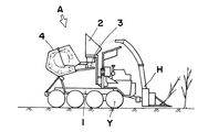
図1に示す第1のロールベーラAは、機体1の前端側に設けた連結桿10を、トラクタ等の牽引車の車体に設けた連結ヒッチに連結して、牽引車により牽引させることで走行する被牽引型に構成した形態のものである。
【0004】
この被牽引型のロールベーラAは、機体1の前面側の上面に、収穫されて細断された飼料作物等の短い被成形材料を受け入れるホッパ2を装架し、それの底部に装設した排出口20の下方に、そこから繰り出される被成形材料を機体1の後方に向けて搬送する搬送コンベア3を、後方に向け下降傾斜する姿勢として装架し、機体1の後部には、搬送コンベア3により後送する被成形材料をロールベールRに成形して梱包するベールチャンバ4を、後方下方に向け傾斜させた姿勢として装架し、これにより、ベールチャンバ4をそれの受入口aが上向きに傾斜して前方に向け開放する形態として、受入口aから送り込まれた短い被成形材料が、ベールチャンバ4内を周回して受入口aに戻ってきたときの溢出を抑止するようにし、そのため、ベールチャンバ4のフロントチャンバ4aと支点軸S中心に後方に回動するリヤチャンバ4bとの接合面bが、上端側を機体1の後部に倒した傾斜姿勢となるようにしている構成のものである。
【0005】
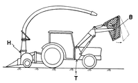
そして、収穫作業初期の圃場外周の口開け刈りや、大区画圃場での中割り収穫においては、それの機体1に装架したホッパ2に対しての被成形材料の供給を、図3に示しているように、ロールベーラAを牽引させるトラクタと別のトラクタTに装着したハーベスタHにより収穫して細断し放出する飼料作物等の短い被成形材料を、そのトラクタTに装架しておくボンネットワゴンWに受け、そこに所定量集積したところで、そのボンネットワゴンWを反転させて、この被成形材料をロールベーラAの機体1に装架してあるホッパ2内に投入することで行うようにするか、または、図4に示しているように、ハーベスタにより収穫して細断した飼料作物等の短い被成形材料を、トラクタTに装備しておくローダーバケットBに受け入れ、これを、ロールベーラAの機体1に装架したホッパ2上に位置させ、そのローダーバケットBの底を開放させることで、ホッパ2内に投入するようにしていて、通常の収穫作業においては、ロールベーラAを牽引させるトラクタTの側方に装着したハーベスタHにより収穫して細断し放出する被成形材料を直接ホッパ2に吹き込む方式と、ロールベーラAを牽引させるトラクタとは別のトラクタTに装着したハーベスタHにより収穫して細断し放出する被成形材料を伴走しながらホッパ2に吹き込む方式で作業するようにしている。
【0006】
図2に示すロールベーラAは、ホッパ2および搬送コンベア3ならびにベールチャンバ4を装架した機体1に、エンジンおよびそれにより駆動される走行装置Yを装架して、機体1を自走走行し得るようにした自走型のロールベーラでありその機体1の前面側には、フォーレージハーベスタHを装架して、それにより収穫して細断した被成形材料をホッパ2に投入していくようにしてある構成のものである。
【0007】
そして、この自走型のロールベーラAにあっても、それの機体1に装架したホッパ2の底部の排出口20から排出される短い被成形材料を後送する搬送コンベア3およびベールチャンバ4は、後方に向け下降傾斜する姿勢として機体1に装架してある。
【0008】
【発明が解決しようとする課題】
上述のピックアップ装置を具備せず、ハーベスタにより収穫して細断した飼料作物等の短い被成形材料を、ホッパ2に受け入れて、それの底部の排出口20から搬送コンベア3によりベールチャンバ4に送り込んでロールベールに成形する形態のロールベーラAは、細断された飼料作物等の短い被成形材料を対象とすることから、搬送コンベア3を後方に向け下降傾斜させ、ベールチャンバ4を、それの受入口aが前方に向け斜め上向きとなる姿勢として機体1に装架していることで、ベールチャンバ4のリヤチャンバ4bを、支点軸S中心にフロントチャンバ4a側に閉鎖回動させるときの作動が重くなって閉まりにくく、かつ、開き易くなるので、ロック機構を強力化したり、複雑にしなければならず、コスト高となる問題がある。
【0009】
また、短い被成形材料の荷受けをするホッパ2を、一定容積のものとしていることで、フォーレージハーベスタHにより飼料作物等の被成形材料を収穫する作業の口開けの際の、回り刈り方式等で収穫した被成形材料をボンネットワゴンWやローダーバケットBで荷受けして、それを定置させたロールベーラAのホッパ2に投入するときに、ホッパ2の容積が不足して一度に全量を投入することが不可能となり、間欠的投入となって作業能率を悪くする問題がある。
【0010】
また、このことから、フォーレージハーベスタをトラクタの機体の側方に装着し、ロールベーラをトラクタの機体後方に牽引装着した形態としないと、ワンマン作業での能率的な作業が出来ない問題がある。
【0011】
さらに、フォーレージハーベスタにより収穫して細断した被成形材料を、ボンネットワゴンやローダーバケット等で、ロールベーラAのホッパ2に投入し、それをホッパ2の排出口20から順次排出させて、搬送コンベア3によりベールチャンバ4の受入口aに送り込むときに、ホッパ2内にブリッジ現象を発生させて、ベールチャンバ4に対し定量的な送り込みが出来ない場合が多い問題もある。
【0012】
本発明は、従前のロールベーラに生じている上述の問題を解消せしめるためになされたものであって、ベールチャンバのリヤチャンバの開閉回動の作動が軽快に行われ、かつ、ロック機構を簡単な機構としながら、ホッパ2内に受け入れた短い被成形材料を、搬送コンベア3によりベールチャンバ4の受入口aからそのベールチャンバ4内に送り込んでいけるようにする新たな手段を提供することを目的とする。
【0013】
【課題を解決するための手段】
そして、本発明においては、この目的を達成するための手段として、請求項1に記載した、機体1に、被成形材料を受入れて下面に開設せる排出口20から排出するホッパ2と、受入口aからチャンバ内に受け入れる被成形材料をチャンバ内に装備せる一対に対向して回動する駆動チェン82にタイトバー80を並列させて渡架してなる成形装置8によりロールベールRに成形するベールチャンバ4と、ベールチャンバ4内で成形し終えたロールベールRを梱包するトワインまたはネット70を繰り出す繰出機構7とを、ホッパ2が前方に位置しベールチャンバ4が後方位置を占め繰出機構7が中間に位置するように前後に並列させて装架し、ホッパ2の排出口20の下方から繰出機構7の下方に渡る範囲に、ホッパ2の排出口20から排出される被成形材料をベールチャンバ4の受入口aに向け搬送する搬送コンベア3を装架するロールベーラにおいて、ベールチャンバ4をそれの受入口aが前方に向け開放する姿勢として機体1に装架し、搬送コンベア3の搬送方向の終端部3aを、それの搬送面が後方に向け下降傾斜する傾斜面cとなるよう構成して、その傾斜面cがベールチャンバ4の受入口aからベールチャンバ4内に突入するよう搬送方向に延出させて、受入口aの下半側を塞ぐように配位して機体1に装架することを特徴とするロールベーラ。
および請求項2に記載した、機体1は、それの前面側に前方に向けて突出する連結桿10を設け、ホッパ2を機体1の前面側に装架し、搬送コンベア3を被成形材料を後送するよう装架し、ベールチャンバ4を受入口aが前方に向けて機体1の後部側に装架して、被牽引型に形成し、そのホッパ2の前壁2aをホッパ主体2bに対し別体に形成して、下端部を支軸Pにより軸支し、アクチュエータ5を連繋して、それの作動により支軸P中心に前後に傾斜回動するよう機体1に装架し、この前壁2aに、ホッパ主体2bの左右の側壁21に重合してスライドするスライド壁22を連結して、ホッパ2の容量が連結桿10の上方において前壁2aの回動により拡縮するようにしたことを特徴とする請求項1記載のロールベーラ。
ならびに請求項3に記載した、ホッパ2内に、駆動されて回動するアジテータ6を設け、そのアジテータ6の回転軸60に回転動力を伝導する伝導機構に、動力伝導の断接機構を設け、その断接機構を、ベールチャンバ4内で成形し終えたロールベールRを梱包するトワインまたはネット70を繰出機構7の停止によりオンに作動するよう制御せしめて、アジテータ6の駆動をトワインまたはネット70の繰出時からロールベール成形完了後放出し、後部ベールチャンバ4bが閉じられるまでの間に一時、中断するようにすることを特徴とする請求項1記載のロールベーラ。
を提起するものである。
【0014】
【発明の実施の形態】
本発明によるロールベーラAは、機体1に、短い被成形材料を受け入れるホッパ2と、そのホッパ2の底部の排出口20から排出される被成形材料を後送する搬送コンベア3と、それにより搬送されてくる被成形材料を受入口aから受け入れてロールベールに成形して梱包するベールチャンバ4とを装架し、そのベールチャンバ4は、前半側のフロントチャンバ4aを機体1に固定して装架し、後半側のリヤチャンバ4bを、支点軸S中心に後方上方に向け開放回動するように機体1に対し軸架するが、それのホッパ2は、それの内容量が拡縮するよう構成して機体1に装架する。
【0015】
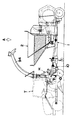
このホッパ2の内容量の拡縮は、例えば、図5乃至図7に示している実施例のように、ホッパ2の前壁2aを、ホッパ主体2bと別体に形成して、それの下端部を機体1に設ける支軸P中心に前後に傾斜回動するよう軸支し、これと機体1との間に伸縮する油圧シリンダ等のアクチュエータ5を設け、この前壁2aに、ホッパ主体2bの左右の側壁21と重合するスライド壁22を連結しておくことで、アクチュエータ5の作動により、この前壁2aを、図5において鎖線および実線に示している状態位置の間を前後に回動させることで、内容積が前後に拡巾し、また、縮小するようにすることが被成形材料の繰り出し時のブリッジ現象防止にも有効である。
【0016】
このホッパ2の内容量の拡縮手段は、図5乃至図7に示した実施例のように、ロールベーラAを、それの機体1の前端側に設けた連結桿10をトラクタの機体の後面の連結ヒッチに連結して牽引させる被牽引型に構成した場合に、ホッパ2の容量の拡縮のための前壁2aの傾斜回動が、連結桿10と連結ヒッチとの連結部の上方における空間を利用して行われることとなり、かつ、前壁2aを下端側の支軸P中心に傾斜回動させることから、受け入れた被成形材料を底部の排出口20に順次流下誘導させる作動に殆ど影響を与えずにその容量の拡縮変更が行えるようになる。
【0017】
また、このホッパ2内腔の底部で排出口20のすぐ上方位置には、軸60中心に撹拌翼61が回動するアジテータ6を装架して、それの駆動によりホッパ2内の被成形材料を撹拌揺動させるようにするが、そのアジテータ6の駆動は、ベールチャンバ4内に送り込んだ被成形材料の成形が、所定の大きさに達して、その圧力を検出する圧力センサの作動により、トワインまたはネットの繰出機構7が始動して梱包していく際の、そのトワインまたはネットを繰り出している間は、後部チャンバ4bが閉じられるまで、このアジテータ6の駆動を一時遮断して、ベールチャンバ4に対する被成形材料の送り込みを停止させ、この間に余分な被成形材料が送り込まれないようにする。
【0018】
このアジテータ6の駆動を、トワインまたはネットを繰り出す繰出機構7が作動している間、後部チャンバ4bが閉じられるまで作動を停止させる手段は、ベールチャンバ4内の被成形材料が所定の大きさのロールに成形されて、圧力感知センサが所定圧力を検知する作動を行うことで、トワインまたはネットの繰出機構7が始動したときに、それに連動してアジテータ6の回転軸の駆動機構に設けておくクラッチ機構がオフに作動するようになればよく、適宜に構成してよいものであるが、実施例においては、図8および図9・図10に示しているように、搬送コンベア3の終端側のプーリ32の回転軸35を、アジテータ6の回転軸60に回転動力を伝導する伝導機構6aの入力軸とし、この回転軸35に、入力側の伝導ギヤ62を回転自在に嵌装して、それの側面にクラッチ歯64aを設け、それの隣側位置に、該回転軸35に対し回転方向に係合する摺動子63を軸方向にスライド自在に嵌装して、それの前記伝導ギヤ62と対向する側面に前述クラッチ歯64aと離接自在に噛み合うクラッチ歯64bを設けて、摺動子63のスライドによりクラッチ歯64aとクラッチ歯64bとの噛合と解放を行わすことで、アジテータ6の回転軸60に対する回転動力の伝導をオン・オフするクラッチ64を構成する。そして、その摺動子63を摺動させるシフター65に、モータMの作動によりロッド66が出入作動するアクチェータ67を連繋しておいて、そのアクチュエータ67の作動を、トワインまたはネット70の繰出機構7が圧力感知センサ(図示せず)の感知作動により作動開始したとき、アクチュエータ67がロッド66を引き込ませるように作動して、噛合クラッチ64をオフの位置にシフトしてアジテータ6の回転を停止状態に保持するようになり、トワインまたはネット70の成形ロールに対する巻き付け終了後、リヤチャンバ4bを開放してロールベールRを放出してリヤチャンバ4bが閉じられ、そのリヤチャンバ4bの閉まりが検出されることで、アクチェータ67のロッド66が押し出されて図10に示すように駆動軸35と伝導ギヤ62とを接続状態としてアジテータ6の回転軸60に動力を伝導するようにしている。
【0019】
ホッパ2の底部の排出口20から排出されて、搬送コンベア3により後送される短い被成形材料を、受入口aから受け入れてロールベールに成形するよう機体1に装架するベールチャンバ4は、前面側に受入口aを形成して機体1に固定装架するフロントチャンバ4aと、それの後面側に支軸S中心に後方上方に向け開放回動するよう装架するリヤチャンバ4bとで構成して、機体1の後部側に装架するが、そのとき、通常のピックアップ装置を具備する長い被成形材料をロールベールに成形する形態のロールベーラのベールチャンバのように、受入口aが前方に向けて開放する水平な姿勢として機体1に装架してよい。
【0020】
また、フロントチャンバ4aの後面側の開放口とリヤチャンバ4bの前面側の開放口とが閉じ合わされて接合する接合面bも、図8にあるように、下方に向かい後方に寄る後方に傾斜した姿勢となるように構成して、これにより、リヤチャンバ4bの支点軸S中心とする開閉回動が軽快に行え、かつ、閉鎖回動させた状態を保持させるロック機構を簡略なものとするようにしておく。
【0021】
そして、このベールチャンバ4の受入口aに、ホッパ2の排出口20から排出される短い被成形材料を搬送する搬送コンベア3は、それの搬送方向の終端部3aが、ベールチャンバ4の受入口aからそのベールチャンバ4内に突入した状態となるように、搬送方向に延出させておき、かつ、その終端部3aの搬送面が、後方に向け下降傾斜して、ベールチャンバ4内で成形されるロールベールRの周面の下半側に対向する傾斜面cとなって、受入口aの下半側を塞ぐようにし、これにより、搬送コンベア3により受入口aからベールチャンバ4内に送り込んだ短い被成形材料が、ベールチャンバ4内を周回して受入口aまできたときに、前面に向け開放するその受入口aから溢出するようになるのを、この搬送コンベア3の終端部3aで抑えながら、再びベールチャンバ4内に送り込んでいくようにする。
【0022】
このように、終端部3aをベールチャンバ4内に突入させる搬送コンベア3は、それのホッパ2の排出口20の下面側に臨む始端部3bから終端部3aまでの間は、略水平または少し後方に向け下降傾斜する形態にしてよい。
【0023】
このことから、搬送コンベア3は、それの搬送ベルト30を、始端側のプーリ31と終端側のプーリ32とにエンドレスに張架して構成するときに、その終端側のプーリ32を、始端側のプーリ31よりも低い位置においてベールチャンバ4内に位置するように配位して軸支し、これらプーリ31・32の中間で、受入口aに臨む部位に、搬送ベルト30の中間を支承する中間プーリ33を、始端側のプーリ31と略揃う高さ位置に配位して軸架して、この中間プーリ33と終端側のプーリ32との間の搬送ベルト30が、下降傾斜する傾斜面cを形成する終端部3aを構成するようにしてよい。
【0024】
この中間プーリ33と終端側のプーリ32との間における搬送ベルト30によりベールチャンバ4内に突入するように構成する搬送コンベア3の終端部3aは、中間プーリ33の手前にもう一つ別のプーリ34を軸支して、中間プーリ33から終端側のプーリ32との間の搬送ベルト30を、始端側のプーリ31から前述の別のプーリ34との間に張架する搬送ベルト30と別にして、ホッパ2の排出口20から短い被成形材料を搬出する搬送ベルト30とは別体に構成してもよい。
【0025】
次に図11は、ベールチャンバ4内に受け入れた短い被成形材料をロールベールRに成形する成形装置8の、ベールチャンバ4の左右の側壁に張設する一対のタイトバー駆動チェン間に渡架装着するタイトバー80…の側面図である。
【0026】
タイトバー80は、円筒を半載した形状に成形して開口面にフランジ81を形成した鋼板よりなる外面部材80aと内面部材80bとを閉じ合わせるように接合し、それらのフランジ81・81を一体に溶接することで、少し偏平に潰れたパイプ状に成形してあり、それの長手方向の両端部におけるフランジ81に、タイトバー80駆動チェン82のリンクプレート83に設けたラグ片84を連結することで、タイトバー80とタイトバー80との間隔を、短い被成形材料の漏下のない極く狭くした状態となって、鎖状の帯板様に連続するようにしてある。
【0027】
次に図12および図13は、上述の本発明手段を実施せるロールベーラAをハーベスタHと組合わせて、ワンマン作業ができるようにした実施例を示している。
【0028】
この例は、ロールベーラAについては被牽引型に形成して、それの機体1の前端側の連結桿10を、トラクタTの本体の後面側に装設せる三点リンクヒッチに連結して、トラクタTにより牽引走行させ、このトラクタTの本体の側面に、ハーベスタHを連結装着する連結機枠90を設けて、それにハーベスタHのフレームを連結装架することで、トラクタTを運転するオペレータが、ワンマンで、被成形材料をハーベスタHにより収穫していく作業とそれにより収穫して細断処理した短い被成形材料をロールベーラAのホッパー2に投入していく作業と、その被成形材料を順次ロールベーラAのベールチャンバ4内に送り込んで成形して梱包し、それを放出していく作業とが、行えるようにしている例である。
【0029】
図12において、90は連結機枠で、平面視においてL字形に形成してあって、それの短辺側となる基端部がトラクタTの本体の後面に沿い長辺側が、トラクタTの本体の側面に沿って前方に突出する姿勢としてその短辺側をトラクタTの本体に組付けることでその本体に装架してある。
【0030】
そして、この連結機枠90の長辺側の突出端部に、ハーベスタHのフレームに設けた取付杆91を連結することで、ハーベスタHをトラクタTの本体の側面に組付け装架し、それの作動部の入力軸92を、トラクタTの動力取出軸PTOに伝導軸93を介して連繋することで、トラクタT側の動力により駆動するようにしてある。
【0031】
そしたまた、このハーベスタHの細断した被成形材料を吹出す吹出筒94の先端を、ロールベーラAのホッパー2の上面側の開放口の上方に臨ませることで、吹出筒94から吐出される被成形材料がホッパー2内に投入されるようにしている。
【0032】
また、本発明によるロールベーラAは、機体1を被牽引型に構成した形態のものについて例示し説明しているが、その機体1は、エンジンおよびそれにより駆動される走行装置を装備せしめて自走して走行する自走型に構成してもよいものである。
【0033】
【発明の効果】
以上説明したように、本発明によるロールベーラは、搬送コンベア3の終端部3aの傾斜面cが、ベールチャンバ4の周壁の一部を形成して、受入口aから受入れた短い被成形材料がベールチャンバ4内を周回して受入口aに戻ってきたときの溢出を抑止するようになって、ベールチャンバ4を受入口aが前方に向け開放する姿勢に装架し得るので、リヤチャンバ4bの開閉回動を軽快にし得る。
【0034】
また、ホッパ2を、牽引車に連結するよう機体1の前面側に前方に突出させて設けた連結桿10の上方において、前壁2aが前後に傾斜回動することで、内容積の拡縮を行わすことから、作業の開始に先立ち回り刈りで収穫した被成形材料を受入れさすための容量の拡張が、機体1の構成および作業に大きな影響を与えることなく行える。
【0035】
また、ホッパ2内に設けるアジテータ6の駆動を、成形し終えたロールベールRを繰出機構7の作動で繰出すトワインまたはネット70により梱包するときに、その繰出機構7が作動して後部チャンバ4bが閉じられるまでの間、中断させることから、梱包時に余分の被成形材料がベールチャンバ4内に送給されてくるのを停止させ得るようになる。
【図面の簡単な説明】
【図1】 従前の被牽引型のロールベーラの側面図である。
【図2】 従前の自走型のロールベーラの側面図である。
【図3】 トラクタに装架した後装型ハーベスタとボンネットワゴンの側面図である。
【図4】 トラクタに装架した後装型ハーベスタとローダーバケットの側面図である。
【図5】 本発明手段を実施せる被牽引型のロールベーラの平面図である。
【図6】 同上の側面図である。
【図7】 同上の前面図である。
【図8】 同上の要部の一部破断した側面図である。
【図9】 同上のアジテータの回転動力の断接機構部分がオフとなった状態時の平面図である。
【図10】 同上部分の断接機構がオンとなった状態時の平面図である。
【図11】 同上ロールベーラのタイトバーの側面図である。
【図12】 同上ロールベーラの、ハーベスタを併設した状態時の平面図である。
【図13】 同上の側面図である。
【符号の説明】
A…ロールベーラ、B…ローダーバケット、H…ハーベスタ、M…モータ、P…下端側の支軸、PTO…動力取出軸、R…ロールベール、S…支点軸、T…トラクタ、W…ボンネットワゴン、Y…走行装置、a…受入口、b…接合面、c…傾斜面、1…機体、10…連結桿、2…ホッパ、2a…前壁、2b…ホッパ主体、20…排出口、21…側壁、22…スライド壁、3…搬送コンベア、3a…終端部、3b…始端部、30…搬送ベルト、31…始端側のプーリ、32…終端側のプーリ、33…中間プーリ、34…プーリ、35…駆動軸、4…ベールチャンバ、4a…フロントチャンバ、4b…リヤチャンバ、5…アクチュエータ、6…アジテータ、60…回転軸、61…撹拌翼、62…伝導ギヤ、63…摺動子、64…嵌合クラッチ、64a・64b…クラッチ歯、65…シフター、66…ロッド、67…アクチュエータ、7…繰出機構、70…ネット、71…作動片、72…検出スイッチ、73…カウンタアーム、74…駆動輪、8…成形装置、80…タイトバー、80a…外面部材、80b…内面部材、81…フランジ、82…駆動チェン、83…リンクプレート、84…ラグ片、90…連結機枠、91…取付杆、92…入力軸、93…伝導軸、94…吹出筒。[0001]
[Technical field to which the invention belongs]
The present invention relates to a roll baler that is fed into a bale chamber mounted on a body of a short material to be formed such as a forage crop that has been harvested and shredded, molded into a roll bale, and packed. Instead of providing a pick-up device for picking up the molding material such as forage crops, a hopper for receiving the molding material is mounted instead, and short coverage such as forage crops harvested and shredded by a forage harvester. The present invention relates to an improvement in a roll baler in which a molding material is received in the hopper, and is sequentially fed from the bottom of the hopper and sent to a bale chamber by a conveyor to form a roll bale.
[0002]
[Prior art]
There are roll balers in the form shown in FIG. 1 and the form shown in FIG. 2 in which a short material such as the above-mentioned shredded forage crop is received in a hopper and formed into a roll bale. .
[0003]
The first roll baler A shown in FIG. 1 travels by connecting a connecting
[0004]
This towed roll baler A has a
[0005]
Then, in the harvesting of the outer periphery of the field at the initial stage of harvesting, or in the mid-range harvesting in the large-division field, the supply of the molding material to the
[0006]
The roll baler A shown in FIG. 2 is capable of self-propelled traveling by mounting the engine and the traveling device Y driven by the engine 1 mounted on the
[0007]
Even in this self-propelled roll baler A, the
[0008]
[Problems to be solved by the invention]
A short molding material such as forage crops harvested by a harvester and shredded without a pickup device as described above is received by the
[0009]
In addition, since the
[0010]
In addition, for this reason, unless a forage harvester is mounted on the side of the tractor body and the roll baler is pulled and mounted on the rear side of the tractor body, there is a problem that efficient work by one-man work cannot be performed.
[0011]
Further, the material to be cut and chopped by the forage harvester is put into the
[0012]
The present invention has been made in order to solve the above-mentioned problems occurring in the conventional roll baler, wherein the opening / closing rotation operation of the rear chamber of the bale chamber is easily performed, and the lock mechanism is a simple mechanism. However, it is an object of the present invention to provide a new means for allowing a short molding material received in the
[0013]
[Means for Solving the Problems]
In the present invention, as means for achieving this object, a
And according to
As well as according to
Is to raise.
[0014]
DETAILED DESCRIPTION OF THE INVENTION
The roll baler A according to the present invention is transported to the machine body 1 by a
[0015]
The expansion / contraction of the inner capacity of the
[0016]
As in the embodiment shown in FIGS. 5 to 7, this means for expanding / reducing the inner capacity of the
[0017]
Further, an
[0018]
The
[0019]
A
[0020]
Further, as shown in FIG. 8, the joining surface b where the opening on the rear surface side of the front chamber 4a and the opening on the front side of the
[0021]
And the
[0022]
In this way, the
[0023]
From this, when the
[0024]
The
[0025]
Next, FIG. 11 shows a mounting between a pair of tight bar drive chains stretched on the left and right side walls of the
[0026]
The
[0027]
Next, FIGS. 12 and 13 show an embodiment in which a roll baler A for carrying out the above-described means of the present invention is combined with a harvester H so that a one-man operation can be performed.
[0028]
In this example, the roll baler A is formed in a towed type, and the connecting
[0029]
In FIG. 12,
[0030]
Then, the harvester H is assembled to the side surface of the main body of the tractor T by connecting a mounting
[0031]
In addition, the tip of the blowing
[0032]
In addition, the roll baler A according to the present invention is illustrated and described with respect to a configuration in which the body 1 is configured as a towed type. However, the body 1 is self-propelled by being equipped with an engine and a traveling device driven by the engine. And may be configured to be self-propelled for traveling.
[0033]
【The invention's effect】
As described above, in the roll baler according to the present invention, the inclined surface c of the
[0034]
In addition, the front wall 2a is tilted back and forth above the connecting
[0035]
Further, when the
[Brief description of the drawings]
FIG. 1 is a side view of a conventional towed roll baler.
FIG. 2 is a side view of a conventional self-propelled roll baler.
FIG. 3 is a side view of a rear-mounted harvester and a bonnet wagon mounted on a tractor.
FIG. 4 is a side view of a rear mounted harvester and a loader bucket mounted on a tractor.
FIG. 5 is a plan view of a towed roll baler for implementing the means of the present invention.
FIG. 6 is a side view of the above.
FIG. 7 is a front view of the above.
FIG. 8 is a partially cutaway side view of the main part of the above.
FIG. 9 is a plan view when the connecting / disconnecting mechanism portion of the rotational power of the agitator is turned off.
FIG. 10 is a plan view showing a state where the connecting / disconnecting mechanism of the same part is turned on.
FIG. 11 is a side view of the tight bar of the above-described roll baler.
FIG. 12 is a plan view of the above-described roll baler when a harvester is also provided.
FIG. 13 is a side view of the above.
[Explanation of symbols]
A ... roll baler, B ... loader bucket, H ... harvester, M ... motor, P ... support shaft on the lower end side, PTO ... power take-off shaft, R ... roll bale, S ... fulcrum shaft, T ... tractor, W ... bonnet wagon, Y ... traveling device, a ... receiving port, b ... joint surface, c ... inclined surface, 1 ... machine body, 10 ... connecting rod, 2 ... hopper, 2a ... front wall, 2b ... hopper main body, 20 ... discharge port, 21 ... Side walls, 22 ... slide walls, 3 ... conveyor, 3a ... terminal, 3b ... start end, 30 ... conveying belt, 31 ... start end pulley, 32 ... end pulley, 33 ... intermediate pulley, 34 ... pulley, 35 ... Drive shaft, 4 ... Bale chamber, 4a ... Front chamber, 4b ... Rear chamber, 5 ... Actuator, 6 ... Agitator, 60 ... Rotating shaft, 61 ... Stirring blade, 62 ... Conduction gear, 63 ... Slider, 64 ... Mating clutch, 6 a · 64b ... clutch teeth, 65 ... shifter, 66 ... rod, 67 ... actuator, 7 ... feeding mechanism, 70 ... net, 71 ... operating piece, 72 ... detection switch, 73 ... counter arm, 74 ... drive wheel, 8 ... Molding device, 80 ... tight bar, 80a ... outer member, 80b ... inner member, 81 ... flange, 82 ... drive chain, 83 ... link plate, 84 ... lug piece, 90 ... coupling machine frame, 91 ... mounting rod, 92 ... input Shaft, 93... Conduction shaft, 94.
Claims (3)
Priority Applications (5)
| Application Number | Priority Date | Filing Date | Title |
|---|---|---|---|
| JP2001352852A JP3976552B2 (en) | 2001-11-19 | 2001-11-19 | Roll baler |
| DE60218400T DE60218400T2 (en) | 2001-11-19 | 2002-07-26 | Round baler |
| ES02255251T ES2280486T3 (en) | 2001-11-19 | 2002-07-26 | PACKING MACHINE OR MACHINE TO FORM CYLINDRICAL BALES. |
| EP02255251A EP1312253B1 (en) | 2001-11-19 | 2002-07-26 | Roll-baler |
| US10/207,807 US7509785B2 (en) | 2001-11-19 | 2002-07-31 | Roll-baler |
Applications Claiming Priority (1)
| Application Number | Priority Date | Filing Date | Title |
|---|---|---|---|
| JP2001352852A JP3976552B2 (en) | 2001-11-19 | 2001-11-19 | Roll baler |
Publications (2)
| Publication Number | Publication Date |
|---|---|
| JP2003143936A JP2003143936A (en) | 2003-05-20 |
| JP3976552B2 true JP3976552B2 (en) | 2007-09-19 |
Family
ID=19164973
Family Applications (1)
| Application Number | Title | Priority Date | Filing Date |
|---|---|---|---|
| JP2001352852A Expired - Lifetime JP3976552B2 (en) | 2001-11-19 | 2001-11-19 | Roll baler |
Country Status (5)
| Country | Link |
|---|---|
| US (1) | US7509785B2 (en) |
| EP (1) | EP1312253B1 (en) |
| JP (1) | JP3976552B2 (en) |
| DE (1) | DE60218400T2 (en) |
| ES (1) | ES2280486T3 (en) |
Families Citing this family (37)
| Publication number | Priority date | Publication date | Assignee | Title |
|---|---|---|---|---|
| JP3843056B2 (en) * | 2002-10-18 | 2006-11-08 | 株式会社タカキタ | Roll baler |
| JP4595049B2 (en) * | 2004-08-25 | 2010-12-08 | 株式会社Ihiスター | Roll baler |
| US7818954B2 (en) * | 2007-05-03 | 2010-10-26 | Vermeer Manuafcturing Company | Corn stalk baling method and apparatus |
| US7743595B2 (en) * | 2007-07-06 | 2010-06-29 | Her Majesty The Queen In Right Of Canada As Represented By The Minister Of Agriculture And Agri-Food Canada | Device and method for harvesting woody crops |
| JP4934100B2 (en) * | 2007-08-31 | 2012-05-16 | 株式会社Ihiスター | Roll baler |
| JP5060380B2 (en) * | 2008-04-24 | 2012-10-31 | 株式会社Ihiスター | Roll baler |
| US7900557B2 (en) * | 2009-04-09 | 2011-03-08 | Lextron, Inc. | System and method for automated application of inoculants onto forage materials |
| US7743699B1 (en) * | 2009-04-09 | 2010-06-29 | Lextron, Inc. | System for automated application of inoculants onto forage materials |
| US20100326037A1 (en) * | 2009-06-24 | 2010-12-30 | Dillon Ben N | Crop Residue Baler Integrated with Harvester, Method for Baling Crop Residue, and Resulting Trapezoidal Crop Residue Bale |
| US8291818B2 (en) * | 2009-07-31 | 2012-10-23 | Agco Corporation | Baler density control mechanism and method |
| US20110023439A1 (en) * | 2009-07-31 | 2011-02-03 | Agco Corporation | Biomass Deflector |
| US20110023440A1 (en) * | 2009-07-31 | 2011-02-03 | Agco Corporation | Method For Projecting Biomass From A Combine Harvester |
| US8443580B2 (en) | 2009-07-31 | 2013-05-21 | Agco Corporation | Baler pickup for collecting biomass from a combine harvester |
| US8490375B2 (en) * | 2009-07-31 | 2013-07-23 | Agco Corporation | Baler collector for collecting biomass from a combine harvester |
| US20110023436A1 (en) * | 2009-07-31 | 2011-02-03 | Agco Corporation | Baler Tongue for Collecting Biomass |
| US8464508B2 (en) | 2009-07-31 | 2013-06-18 | Agco Corporation | Biomass baler |
| CA2783231C (en) * | 2009-12-09 | 2018-12-04 | Daniel Gaudreault | Apparatus and method for chipping tree branches and the like and baling wood chips formed from such chipping activites |
| NL1037742C2 (en) * | 2010-02-23 | 2011-08-24 | Forage Innovations Bv | Wrapper for wrapping bales of crop material. |
| US8677724B2 (en) | 2010-10-25 | 2014-03-25 | Deere & Company | Round baler for baling crop residue |
| DE102011083941A1 (en) | 2010-10-25 | 2012-04-26 | Deere & Company | Method for retrofitting baler utilized in harvester for e.g. pressing agricultural crops into bales, has attaching belt conveyer with rear end at baler and positioning accumulator chamber at replacement drawbar and above belt conveyer |
| US8733073B2 (en) * | 2011-09-22 | 2014-05-27 | E I Du Pont De Nemours And Company | System and apparatus for cutting, windrowing, and baling material in a single pass |
| US9510509B2 (en) * | 2012-08-31 | 2016-12-06 | Deere & Company | Two-stage harvesting system |
| US9084394B2 (en) | 2013-02-22 | 2015-07-21 | CNH Industrial Canada, LTD | Continuous crop accumulator for agricultural harvesters |
| JP6333562B2 (en) * | 2014-01-27 | 2018-05-30 | 株式会社タカキタ | Roll baler |
| US10363716B2 (en) * | 2015-05-19 | 2019-07-30 | Daniel Gaudreault | Shredding and baling apparatus and method |
| US11432465B2 (en) * | 2014-05-19 | 2022-09-06 | Gyro-Trac Corporation | Shredding and baling apparatus and method |
| US10721872B2 (en) * | 2014-05-19 | 2020-07-28 | Daniel Gaudreault | Baling apparatus and method |
| CN107074452B (en) * | 2014-07-23 | 2020-01-21 | 凯斯纽荷兰(中国)管理有限公司 | Feeding system for agricultural implement |
| US9345196B1 (en) * | 2014-11-05 | 2016-05-24 | Deere & Company | Cotton handling system with mechanical sequencing |
| US20170055457A1 (en) * | 2015-08-31 | 2017-03-02 | Vermeer Manufacturing Company | Power Transmission Couplers And Bale Processors Using Same |
| US10596776B1 (en) * | 2015-11-06 | 2020-03-24 | Swift Straw Holdings, LLC | Pine straw baling apparatus and method |
| US11647697B2 (en) * | 2017-05-01 | 2023-05-16 | Bruce Goddard | Rear mount bale spreader |
| CN110884711A (en) * | 2019-12-16 | 2020-03-17 | 呼伦贝尔市蒙拓农机科技股份有限公司 | Trailed Smart Cotton Baler |
| US11547056B2 (en) * | 2020-03-11 | 2023-01-10 | Cnh Industrial America Llc | Frame assembly for an agricultural round baler |
| CH717350A1 (en) * | 2020-04-28 | 2021-10-29 | Meier Philipp | Round baler with forage harvester. |
| CN112715173A (en) * | 2020-12-21 | 2021-04-30 | 刘莹 | Green fodder rolling processing equipment |
| CN112550795A (en) * | 2020-12-24 | 2021-03-26 | 海盐三湾塑业有限公司 | Packing apparatus of rendition membrane book |
Family Cites Families (26)
| Publication number | Priority date | Publication date | Assignee | Title |
|---|---|---|---|---|
| US2017971A (en) * | 1932-02-24 | 1935-10-22 | Willis V Howard | Hay press feeder |
| US2627223A (en) * | 1949-08-08 | 1953-02-03 | Howard J Berge | Baling machine for compacting straw and stalks from harvesting machines into cylindrical bales |
| US3722197A (en) * | 1972-01-03 | 1973-03-27 | G Vermeer | Method and machine for forming a large round bale of a fibrous material |
| DE2219976A1 (en) * | 1972-04-24 | 1973-11-08 | Krone Bernhard Gmbh Maschf | LOADING WAGON |
| US3826354A (en) * | 1973-09-26 | 1974-07-30 | P Patz | Hopper and feed leveler for a tapered bed conveyor |
| US3910178A (en) * | 1973-10-12 | 1975-10-07 | Sperry Rand Corp | Apparatus for wrapping a round bale formed in a round bale forming machine |
| US4169347A (en) * | 1974-09-19 | 1979-10-02 | International Harvester Company | Belt-type baler for cylindrical bales |
| DE2553492C2 (en) * | 1975-11-28 | 1984-03-22 | Gebrüder Welger GmbH & Co KG, 3340 Wolfenbüttel | Dissolving and distributing device for roll bales made from agricultural stalks |
| US4022121A (en) * | 1976-08-18 | 1977-05-10 | Sperry Rand Corporation | Adjustment cams for removing end play from tying mechanism on a baler |
| US4229934A (en) * | 1979-04-13 | 1980-10-28 | Chromalloy American Corporation | Bale rolling machine |
| JPS5745792Y2 (en) * | 1979-06-22 | 1982-10-08 | ||
| US4335855A (en) * | 1980-06-27 | 1982-06-22 | Staskal Maynard L | Dry particle distributor for the treatment of forage |
| US4352267A (en) * | 1980-12-31 | 1982-10-05 | Mellinger Manufacturing Co., Inc. | Chemical dispenser for a round baler |
| US4375187A (en) * | 1981-07-13 | 1983-03-01 | The Paul Revere Corporation | Ejection mechanism for a round baler |
| CH662102A5 (en) * | 1983-07-29 | 1987-09-15 | Ferag Ag | METHOD AND DEVICE FOR STORING CONTINUOUSLY, IN PARTICULAR PRODUCTS INCLUDING IN A DANDEL INFORMATION, IN PARTICULAR PRINTED PRODUCTS. |
| US4567998A (en) * | 1984-02-01 | 1986-02-04 | International Stock Food Company | Chemical dispenser for hay baler |
| DE3734186A1 (en) * | 1987-10-09 | 1989-04-27 | Welger Geb | COLLECTING ROLLER PRESS |
| US5377481A (en) * | 1993-03-17 | 1995-01-03 | Sibley; Duane L. | Apparatus for baling bulk fibrous material |
| SE9302191L (en) * | 1993-06-24 | 1994-12-19 | Bala Ind Ab | Device at round baling plant |
| DE19542645C2 (en) * | 1995-11-15 | 2000-11-09 | Friatec Rpp Gmbh System Altvat | Changing table |
| IES80587B2 (en) * | 1997-07-25 | 1998-10-07 | Comtor Limited | A combined compacting and wrapping machine |
| US5878552A (en) * | 1997-07-31 | 1999-03-09 | Wingert; Paul R. | Apparatus and method for bagging agricultural feed |
| JP4001193B2 (en) * | 1999-06-28 | 2007-10-31 | 独立行政法人農業・食品産業技術総合研究機構 | Roll baler |
| DE19932336A1 (en) * | 1999-07-10 | 2001-01-11 | Lely Welger Maschinenfabrik Gm | Continuously operating agricultural baling press has two conveyors between crop storage chamber and press chamber |
| DE10006384A1 (en) * | 2000-02-12 | 2001-08-16 | Deere & Co | Round baler |
| US6591743B2 (en) * | 2001-02-01 | 2003-07-15 | Deere & Company | Cotton processing system and method of operation |
-
2001
- 2001-11-19 JP JP2001352852A patent/JP3976552B2/en not_active Expired - Lifetime
-
2002
- 2002-07-26 DE DE60218400T patent/DE60218400T2/en not_active Expired - Lifetime
- 2002-07-26 EP EP02255251A patent/EP1312253B1/en not_active Expired - Lifetime
- 2002-07-26 ES ES02255251T patent/ES2280486T3/en not_active Expired - Lifetime
- 2002-07-31 US US10/207,807 patent/US7509785B2/en not_active Expired - Lifetime
Also Published As
| Publication number | Publication date |
|---|---|
| ES2280486T3 (en) | 2007-09-16 |
| JP2003143936A (en) | 2003-05-20 |
| EP1312253A1 (en) | 2003-05-21 |
| DE60218400D1 (en) | 2007-04-12 |
| EP1312253B1 (en) | 2007-02-28 |
| US7509785B2 (en) | 2009-03-31 |
| DE60218400T2 (en) | 2007-11-08 |
| US20030093979A1 (en) | 2003-05-22 |
Similar Documents
| Publication | Publication Date | Title |
|---|---|---|
| JP3976552B2 (en) | Roll baler | |
| JP3843056B2 (en) | Roll baler | |
| US8132659B2 (en) | Tractor mounted unloading conveyor | |
| KR100868916B1 (en) | Combine | |
| US20110073440A1 (en) | Grain bag extractor augers | |
| CA2709730C (en) | Implement for transporting and wrapping large bales | |
| BE1020303A3 (en) | COMBINED PACKER AND STOWER. | |
| US3951288A (en) | Large round bale handling apparatus | |
| CN111480458B (en) | Harvester | |
| JP4920327B2 (en) | Shredded roll baler | |
| JP3939125B2 (en) | Conveyor for roll baler | |
| JP3831680B2 (en) | Combine harvester | |
| KR0130873B1 (en) | Combine Grain Tanks | |
| CA2728450A1 (en) | Grain bag unloader having an improved grain flow | |
| JPH05146216A (en) | Grain-discharging apparatus | |
| US11930740B2 (en) | Threshing apparatus | |
| GB2438064A (en) | Silo cutting attachment for mechanical excavator | |
| KR20250136175A (en) | Silage forage feeder with conveyor | |
| JPH1189380A (en) | Mowing grass collection device | |
| US5327711A (en) | Baler feeding apparatus | |
| JP2004154067A (en) | Injection guide device for molding material in hopper of roll baler | |
| EP0099953B1 (en) | Rectangular bale press | |
| JPH1094320A (en) | Threshing equipment | |
| JP4576682B2 (en) | Combine binding machine | |
| JP4420160B2 (en) | Combine |
Legal Events
| Date | Code | Title | Description |
|---|---|---|---|
| A621 | Written request for application examination |
Free format text: JAPANESE INTERMEDIATE CODE: A621 Effective date: 20040802 |
|
| A521 | Request for written amendment filed |
Free format text: JAPANESE INTERMEDIATE CODE: A523 Effective date: 20040907 |
|
| RD02 | Notification of acceptance of power of attorney |
Free format text: JAPANESE INTERMEDIATE CODE: A7422 Effective date: 20040907 |
|
| A977 | Report on retrieval |
Free format text: JAPANESE INTERMEDIATE CODE: A971007 Effective date: 20060713 |
|
| A131 | Notification of reasons for refusal |
Free format text: JAPANESE INTERMEDIATE CODE: A131 Effective date: 20060725 |
|
| A521 | Request for written amendment filed |
Free format text: JAPANESE INTERMEDIATE CODE: A523 Effective date: 20060921 |
|
| A131 | Notification of reasons for refusal |
Free format text: JAPANESE INTERMEDIATE CODE: A131 Effective date: 20070306 |
|
| A521 | Request for written amendment filed |
Free format text: JAPANESE INTERMEDIATE CODE: A523 Effective date: 20070425 |
|
| TRDD | Decision of grant or rejection written | ||
| A01 | Written decision to grant a patent or to grant a registration (utility model) |
Free format text: JAPANESE INTERMEDIATE CODE: A01 Effective date: 20070529 |
|
| A61 | First payment of annual fees (during grant procedure) |
Free format text: JAPANESE INTERMEDIATE CODE: A61 Effective date: 20070619 |
|
| FPAY | Renewal fee payment (event date is renewal date of database) |
Free format text: PAYMENT UNTIL: 20100629 Year of fee payment: 3 |
|
| R150 | Certificate of patent or registration of utility model |
Free format text: JAPANESE INTERMEDIATE CODE: R150 Ref document number: 3976552 Country of ref document: JP Free format text: JAPANESE INTERMEDIATE CODE: R150 |
|
| FPAY | Renewal fee payment (event date is renewal date of database) |
Free format text: PAYMENT UNTIL: 20110629 Year of fee payment: 4 |
|
| R250 | Receipt of annual fees |
Free format text: JAPANESE INTERMEDIATE CODE: R250 |
|
| FPAY | Renewal fee payment (event date is renewal date of database) |
Free format text: PAYMENT UNTIL: 20120629 Year of fee payment: 5 |
|
| R250 | Receipt of annual fees |
Free format text: JAPANESE INTERMEDIATE CODE: R250 |
|
| FPAY | Renewal fee payment (event date is renewal date of database) |
Free format text: PAYMENT UNTIL: 20130629 Year of fee payment: 6 |
|
| R250 | Receipt of annual fees |
Free format text: JAPANESE INTERMEDIATE CODE: R250 |
|
| R250 | Receipt of annual fees |
Free format text: JAPANESE INTERMEDIATE CODE: R250 |
|
| R250 | Receipt of annual fees |
Free format text: JAPANESE INTERMEDIATE CODE: R250 |
|
| S533 | Written request for registration of change of name |
Free format text: JAPANESE INTERMEDIATE CODE: R313533 |
|
| S533 | Written request for registration of change of name |
Free format text: JAPANESE INTERMEDIATE CODE: R313533 |
|
| R350 | Written notification of registration of transfer |
Free format text: JAPANESE INTERMEDIATE CODE: R350 |
|
| R250 | Receipt of annual fees |
Free format text: JAPANESE INTERMEDIATE CODE: R250 |
|
| R250 | Receipt of annual fees |
Free format text: JAPANESE INTERMEDIATE CODE: R250 |
|
| R250 | Receipt of annual fees |
Free format text: JAPANESE INTERMEDIATE CODE: R250 |
|
| R250 | Receipt of annual fees |
Free format text: JAPANESE INTERMEDIATE CODE: R250 |
|
| R250 | Receipt of annual fees |
Free format text: JAPANESE INTERMEDIATE CODE: R250 |
|
| R250 | Receipt of annual fees |
Free format text: JAPANESE INTERMEDIATE CODE: R250 |
|
| R250 | Receipt of annual fees |
Free format text: JAPANESE INTERMEDIATE CODE: R250 |
|
| EXPY | Cancellation because of completion of term |