JP3973344B2 - Substrate processing equipment - Google Patents
Substrate processing equipment Download PDFInfo
- Publication number
- JP3973344B2 JP3973344B2 JP2000127282A JP2000127282A JP3973344B2 JP 3973344 B2 JP3973344 B2 JP 3973344B2 JP 2000127282 A JP2000127282 A JP 2000127282A JP 2000127282 A JP2000127282 A JP 2000127282A JP 3973344 B2 JP3973344 B2 JP 3973344B2
- Authority
- JP
- Japan
- Prior art keywords
- substrate
- support plate
- rotation support
- plate
- rotation
- Prior art date
- Legal status (The legal status is an assumption and is not a legal conclusion. Google has not performed a legal analysis and makes no representation as to the accuracy of the status listed.)
- Expired - Fee Related
Links
Images


Landscapes
- Liquid Crystal (AREA)
- Coating Apparatus (AREA)
- Weting (AREA)
- Container, Conveyance, Adherence, Positioning, Of Wafer (AREA)
- Exposure Of Semiconductors, Excluding Electron Or Ion Beam Exposure (AREA)
- Cleaning Or Drying Semiconductors (AREA)
Description
【0001】
【発明の属する技術分野】
本発明は、液晶表示器用のガラス基板や半導体ウェハなどの基板を水平面内で回転させながら洗浄処理や乾燥処理などの所要の処理を施す基板処理装置に係り、特にサイズの大きな基板を処理するのに適した基板処理装置に関する。
【0002】
【従来の技術】
従来のこの種の基板処理装置として、例えが特開平9−330904号公報に開示された装置を図7を参照して説明する。
この基板処理装置は、半導体ウェハなどの基板Wを水平面内で回転させながら、基板Wの表裏面に薬液処理、洗浄処理、乾燥処理をその順に施す装置である。この基板処理装置は、基板Wを水平姿勢で保持する回転支持板1を備えている。回転支持板1は平面視で円形状の平板であって、その上面に基板Wの外周縁に係合して基板Wを支持する複数個の駆動ピン2が立設されている。この駆動ピン2は、基板Wを支える大径の円柱状のピン下部2aと小径のピン上部2bが一体に連結した段付き構造となっている。
【0003】
回転支持板1の回転中心部に開口1aがあり、この開口1aに筒軸3が連結固定されている。この筒軸3はベルト機構4を介してモータ5に連結されている。筒軸3の中心に沿って液ノズル6が配設されており、この液ノズル6の先端が基板Wの下面中心部に臨んでいる。液ノズル6は薬液供給源および洗浄液供給源に選択的に接続されるようになっている。また、筒軸3と液ノズル6との間隙は窒素ガスなどの不活性ガス供給源に連通接続されている。
【0004】
基板Wを挟んで回転支持板1に平行に対向するように上部回転板7が配設されている。この上部回転板7も回転支持板1と同様に平面視で円形状の平板である。回転支持板1と同様に、上部回転板7の回転中心部に開口7aがあり、この開口7aに筒軸8が連結固定されている。この筒軸8はモータ9の出力軸に連結されている。筒軸8の中心に沿って液ノズル10が配設されており、この液ノズル10の先端が基板Wの上面中心部に臨んでいる。液ノズル6の場合と同様に、液ノズル10も薬液供給源および洗浄液供給源に選択的に接続されており、また、筒軸8と液ノズル10との間隙は不活性ガス供給源に連通接続されている。
【0005】
そして、上下に平行に配置された回転支持板1と上部回転板7を囲むようにカップ11が配設されており、このカップ11の底部に排気管12が連通接続されている。
【0006】
以上のように構成された基板処理装置においては、次にように基板処理が行われる。
まず、上部回転板7が上方に退避した状態で、回転支持板1に基板Wが載置される。この基板Wは駆動ピン2によって支持される。続いて、上部回転板7が回転支持板1に対向する位置(図7の状態)にまで下降する。この状態でモータ5および9が始動して、回転支持板1および上部回転板7をそれぞれ同期して回転する。回転支持板1の回転に伴って、その回転力が駆動ピン2を介して基板Wに伝達され、基板Wも回転支持板1および上部回転板7と同期して回転する。基板Wの回転数が所定値に達すると、上下の開口1a、7aから不活性ガスを導入しながら、上下の液ノズル6、10から薬液および洗浄液をその順に供給して、基板Wの表裏面の処理を行う。基板Wの薬液処理および洗浄処理が終わると、基板Wを回転させながら不活性ガスだけを導入して、基板Wの乾燥処理を行う。
【0007】
このように薬液処理から乾燥処理までの間、回転支持板1と上部回転板7とで区画された偏平な処理空間S内で基板Wが処理される。基板Wに供給された薬液や洗浄液は不活性ガスとともに、回転支持板1および上部回転板7の回転による遠心力によって外方に追いやられて処理空間Sの外周端から排出され、カップ11の底部に連通する排気管12から排出される。このとき基板Wから振り切られた薬液や洗浄液がカップ11の内面に当たって飛散したとしても、基板Wの上下は回転支持板1と上部回転板7に覆われているので、薬液や洗浄液のミストで基板Wが汚染されることがない。また、処理空間Sからは不活性ガスが絶えず噴出しているので、ミストが処理空間S内に侵入して基板Wを汚染することもない。
【0008】
即ち、液処理の場合は、処理中の基板Wの端縁から振り切られた液滴がカップ11などで跳ね返っても、上下の板部材で遮断されて基板Wに再付着するのが防止でき、周囲に浮遊している処理液のミストなども遮断されて基板Wに再付着するのが防止できる。また、乾燥処理の場合は、処理中の基板Wと周囲の雰囲気とが遮蔽され、基板Wへの周囲の雰囲気の影響を防止できる。このように基板Wの表面と裏面にそれぞれ近接配置させた2つの板部材は基板Wを支持すると共に遮蔽部材として機能する。
【0009】
【発明が解決しようとする課題】
しかしながら、このような構成を有する従来例の場合には、次のような問題がある。近年の半導体ウェハなどの基板の大径化に伴い、回転支持板1や上部回転板7が大型化している。そのため回転支持板1や上部回転板7の重量が飛躍的に重くなり、大きな駆動力を必要とするようになった。
【0010】
一方、液晶表示器用の矩形状のガラス基板の場合には、その外形が850mm×1000mmにも及ぶので、このような角形基板は大形化に伴い、大きく波打って湾曲する問題を引き起こしている。この湾曲は基板Wを搬送・支持する上で配慮が必要なもので、図7の従来装置においては、特に駆動ピン2における基板Wの浮き上がりとして顕在化してきている。
【0011】
基板Wの浮き上がりに関して図7の従来例で説明する。駆動ピン2に挟持されている状態の基板Wの重心は、必ずしも回転支持板1の中心軸上に位置しているとは限らず、中心軸に対して偏心している場合がある。すなわち、処理装置の組立て精度上、基板Wの重心を回転支持板1の中心軸に位置させるのは難しく、基板Wの重心は回転支持板1の中心軸に位置しない。一方、処理中においては基板Wは高速回転しているから、基板Wには遠心力が作用している。したがって、処理中の基板Wには偏心力が作用しており、処理中の基板Wは不安定な状態となっている。
【0012】
また、基板Wの下方の液ノズル6から吐出される処理液の噴射力が、基板Wの上方の液ノズル10よりも大きい場合は、基板Wが浮き上がる可能性がある。すなわち、基板Wの下方の液ノズル6から基板Wの下面に処理液が吐出される限り、基板Wの少なくとも一部分が浮き上がることになる。これらの場合、基板Wは駆動ピン2から離脱し、損傷するおそれがある。これらの状況に対して別途、駆動ピン2の上部に押え部材を配置して基板Wの浮き上がりを防止することが考えられる。
【0013】
しかしながら、大型基板はその浮き上がりによる端部の移動量が大きく、駆動ピンや押え部材との当接により破損してしまう問題があった。即ち、剛性のある回転支持板1で基板Wを保持すると、基板Wが駆動ピンに当接することに対する追従性、言い換えると当接力を吸収する機能がないので、破損してしまうという問題があった。
【0014】
本発明は、このような事情に鑑みてなされたものであって、基板を回転させて処理を行う基板処理装置において、基板を破損することがない基板処理装置を提供することを主たる目的としている。
【0015】
【課題を解決するための手段およびその作用・効果】
上記目的を達成するために、本発明は、基板を回転させながら基板に所望の処理を行う基板処理装置であって、基板と同等以上の大きさで平板状の回転支持板と、前記回転支持板に立設され、基板の外周端縁に係合して前記基板の水平位置を規制するとともに基板に回転力を伝える複数個の駆動部材と、前記駆動部材で基板を水平姿勢に支持した状態で前記回転支持板を回転する駆動手段と、を備え、前記回転支持板は、可撓性又は弾性変形可能な金属薄板により形成され、更に、回転中心側から半径方向外側に向けてせりあがった傾斜部を備えていることを特徴とする基板処理装置である。
【0016】
請求項2に係る発明は、基板を回転させながら基板に所望の処理を行う基板処理装置であって、基板と同等以上の大きさで平板状の回転支持板と、前記回転支持板に立設され、基板の外周端縁に係合して前記基板の水平位置を規制するとともに基板に回転力を伝える複数個の駆動部材と、前記駆動部材で基板を水平姿勢に支持した状態で前記回転支持板を回転する駆動手段と、前記回転支持板の下面に配置され、円形状で外周端が上方に立設した支持板とを備え、前記回転支持板は、可撓性又は弾性変形可能な金属薄板により形成されたことを特徴とする。
請求項3に係る発明は、請求項1または2に記載の基板処理装置において、前記回転支持板は、ステンレス鋼板であることを特徴とする。
【0017】
請求項4に係る発明は、基板を回転させながら基板に所望の処理を行う基板処理装置であって、基板と同等以上の大きさで平板状の回転支持板と、前記回転支持板に立設され、基板の外周端縁に係合して前記基板の水平位置を規制するとともに基板に回転力を伝える複数個の駆動部材と、前記駆動部材で基板を水平姿勢に支持した状態で前記回転支持板を回転する駆動手段と、を備え、前記回転支持板は、外周端を回転中心側に折り曲げ加工された絞り込み部を有することを特徴とする基板処理装置である。
【0018】
請求項5に係る発明は、請求項4に記載の基板処理装置において、前記回転支持板は、絞り込み部をへら絞り加工にて形成されたことを特徴とする。
【0019】
請求項6に係る発明は、請求項4または請求項5に記載の基板処理装置において、前記回転支持板は、回転中心側から半径方向外側に向けてせり上がった傾斜部を備えていることを特徴とする。
【0020】
本発明の作用は次のとおりである。請求項1に係る発明の基板処理装置においては、基板を破損せずに処理することができる。即ち、前記回転支持板が可撓性又は弾性変形可能な金属薄板で形成されている。即ち、金属とすることで基板を支持する強度を維持することができる。それと共に、可撓性又は弾性変形可能であるため、基板の動きに駆動部材を介して追従し変形しても、その当接力が無くなると元の形に戻り、引き続き処理を続行できる。言い換えると、基板が振動や浮き上がりでその端部が駆動部材に当接しても、その応力を駆動部材を介して回転支持板で吸収することで基板の破損を防止できる。また、回転支持板は、回転中心側から半径方向外側に向けてせりあがった傾斜部を備えているため、この傾斜部により、回転支持板を厚い板材で形成することなく、その撓み剛性を簡単に向上させることができる。
【0021】
請求項2に係る発明の基板処理装置においては、基板を破損せずに処理することができる。即ち、前記回転支持板が可撓性又は弾性変形可能な金属薄板で形成されている。即ち、金属とすることで基板を支持する強度を維持することができる。それと共に、可撓性又は弾性変形可能であるため、基板の動きに駆動部材を介して追従し変形しても、その当接力が無くなると元の形に戻り、引き続き処理を続行できる。言い換えると、基板が振動や浮き上がりでその端部が駆動部材に当接しても、その応力を駆動部材を介して回転支持板で吸収することで基板の破損を防止できる。また、回転支持板の下面に配置され、円形状で外周端が上方に立設した支持板を備えている。こうすることにより回転支持板の撓みは支持板で防止し、回転支持板と基板との隙間を小さくする。よって、回転支持板と基板の隙間で遠心力で排出されるエアーが渦巻くような気流の発生を防止することができる。
請求項3記載の発明は、前記回転支持板をステンレス鋼板で形成する。即ち、これにより回転支持板は良好な可撓性を有し、また弾性変形可能となる。そして、変形しても元の形状に戻って次の基板を受け入れることが可能となる。
【0022】
請求項4記載の発明は、回転支持板の外周端を回転中心側に折り曲げ加工された絞り込み部を有する。それにより、回転支持板は形状が変形しないよう強度を有する事となる。仮に、回転支持板を薄板にて形成したとしても、回転支持板の外周端で撓むのを防止できる。よって、回転支持板を薄く形成し局所的には柔軟性を有しても、形状的に剛性が大きくなるので形状が極度に変形することが防止できる。即ち、回転支持板を薄く軽量化できるので、駆動手段に大きな負荷がかからない。
【0023】
請求項5記載の発明によれば、前記回転支持板の絞り込み部はへら絞り加工にて形成される。このことにより薄板であったとして外形が極度に変形することがなく所望の形状に形成できる。その結果、回転支持板の板厚を薄く形成し局所的には柔軟性を有しても、回転支持板の外周端で撓むのを防止できる。
【0024】
請求項6記載の発明によれば、前記回転支持板が回転中心側から半径方向外側に向けてせり上がった傾斜部を備えているので、比較的に板厚の薄い回転支持板であっても剛性が大きくなり、回転支持板が撓みにくくなる。また、回転支持板を薄くして軽量化することができるので、駆動手段の負荷を一層軽減することができる。
【0025】
【発明の実施の形態】
以下、本発明の実施例を図面を参照して説明する。
ここでは、液晶表示器用のガラス基板の乾燥処理に用いられる基板処理装置を例に採って説明する。ただし、本発明は、ガラス基板の処理に限らず、半導体ウェハなどの各種の基板の処理にも適用することができる。また、本発明が適用できる基板処理は、乾燥処理に限らず、薬液処理や洗浄処理なども含む。さらに、本発明装置は、単一の処理を行うものだけに限らず、薬液処理、洗浄処理、および乾燥処理を同じ装置内で連続して行うものや、洗浄処理と乾燥処理を同じ装置内で連続して行うものなどにも適用可能である。
【0026】
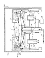
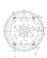
図1は本発明に係る基板処理装置の一実施例の概略構成を示した縦断面図、図2は回転支持板に基板が載置された状態を示した平面図である。
この基板処理装置100は、矩形状のガラス基板(以下、単に「基板」という)Wを保持する回転支持板31を備えている。この基板Wは、例えば縦横長さが850mm×1000mmで、厚みが0.7mmの大形で薄い基板である。
【0027】
回転支持板31には、基板Wを下面から支える複数本、本実施例では図2に示すように12本の支持ピン34と8本の駆動ピン33が立設されている。支持ピン34は回転中心P側に回転中心Pの周りに円形状(図2中に鎖線で示す)に4本、基板W周縁側に8本が配置される。駆動ピン33は基板Wの4角部に対応して2個ずつ配置される。
【0028】
これらの駆動ピン33および支持ピン34は、基板Wの中心部が低く、かつ基板Wが滑らかに湾曲した状態で支えられるように、各々の高さが調節されている。本実施例では基板Wの中心部が外周縁部に比べて4mm程度低くなっている。因みに、大形の薄い角形基板Wを完全に水平に支持するには多数の支持ピン34が必要であり、また、精度上の限界から困難を伴い、基板Wが局所的に波打った状態で支持されやすい。このような状態で基板Wを高速回転させると基板Wが振動するという不都合が生じる。本実施例では、上記のように基板Wを滑らかに湾曲した状態で支持することにより、基板Wの局所的な波打ち(凹凸)を無くし、基板Wを高速回転させたときの基板Wの振動を抑制している。
【0029】
図1に示すように、回転支持板31の回転中心部には開口(気体噴出口)35が設けられている。この開口35に連通するように、回転支持板31の下面に筒軸36が連結接続されている。この筒軸36はベルト機構37を介してモータ38に連結されている。このモータ38は本発明における駆動手段に相当する。筒軸36の中心に沿って液ノズル39が配設されており、この液ノズル39の先端が基板Wの下面中心部に臨んでいる。液ノズル39は開閉弁40を介して純水などの洗浄液を供給する洗浄液供給源に接続されている。また、筒軸36と液ノズル39との間隙は図示しない流量調整弁を介して大気圧雰囲気に開放されるよう構成されている。
【0030】
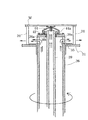
図3に示すように、筒軸36は回転支持板31の開口35に臨んで延在し、回転支持板31より上側に位置する側面にエアーを排出するための排出口36aが開口される。また、筒軸36の上面は液ノズル39が延出するように設けられ、この液ノズル39の側面と筒軸36の間隙である排出口36bからも大気圧雰囲気からのエアーが吐出される。そして、液ノズル39の先端部には、中央部が開口した傘状部材42が嵌め付け固定されている。この傘状部材42によって排出口36bが覆われている。
【0031】
この構成により、回転支持板31が回転するとその遠心力で排出され、回転中心Pに近いほど低圧状態となる。そのため、大気圧雰囲気に開放されている筒軸36と液ノズル39との間隙からポンプ効果によりエアーを吸入する。このエアーは、前述の排出口36a、36bより排出される。
【0032】
さらに、傘状部材42を覆うように、中央が開口した円錐台状のカバー部材44が傘状部材42に近接して配備されている。カバー部材44は筒軸36の上面に支持されて、筒軸36と一体回転するようになっている。カバー部材44の基部周面には、排出口36bから噴出したエアーを流通させるための流通孔44aが開けられている。
【0033】
基板Wを挟んで回転支持板31に対向するように上部回転板32が配設されている。この上部回転板32は基板Wの周縁領域を覆うリング状を呈しており、中央部に直径が約600mm程度の大きな開口32aが開けられている。この開口32aには中央に円形の開口320が設けられた、いわゆるパンチングプレートよりなる流路抵抗部材321が設置してある。そして開口32aの周囲は仕切壁322が立設されている。
【0034】
さらに上部回転板32の上面には、上方に張り出したT字状の係合部46が設置され、係合部46の上部鍔部46aに昇降駆動部47が連結されている。この昇降駆動部47はシリンダー47aのロッド47bが伸縮することでアームバー47cが昇降する。アームバー47cの下面には上述の係合部46に対向して門形アーム47dが配置され、係合部46の上部鍔部46aが係合される。この構成で門形アーム47dが上部鍔部46aに当接して上下動することにより、回転支持板31に支持される処理位置と、基板Wの搬入・搬出を許容する上方の退避位置とにわたって上部回転板32が移動するようになっている。尚、図1では、2つの昇降駆動部47が開示されているが、上部回転板32の上面に等間隔に4つの係合部46が配置され、それに対応して4つの昇降駆動部47が配置される。そして上部回転板32の回転停止位置の制御により、係合部46と門形アーム47dが係合される。
【0035】
上部回転板32の上側に、上部回転板32とは別体の流路抵抗部材48が配設されている。この流路抵抗部材48は、例えばステンレス鋼板に多数の小孔を開けた、いわゆるパンチングプレートであって、ドーナツ状に形成される。そしてその内側縁には仕切壁48aが、外側縁には仕切壁48bが下方に延在して構成される。仕切壁48aは仕切壁322の外周面に近接しており、仕切壁48bはその下端が後述する排気カップ50の上端に当接される。そして仕切壁48bの内面には昇降駆動部47のアームバー47cが連結される。また仕切壁48bの外面には装置100の枠体101に形成された搬入口101aが臨むように構成される。
【0036】
この構成により、昇降駆動部47の昇降すると流路抵抗部材48は上部回転板32との位置関係を保ちながら上下動する。それに伴い仕切壁48bの下端が排気カップ50から離間して、その部位が枠体101の搬入口101aに臨むことにより装置100に基板Wを外部から搬入する搬入口として機能することとなる。即ち、仕切壁48bの下端と排気カップ50上端の間隔が搬入口であり、搬入口101aの蓋として仕切壁48bが機能する。
【0037】
装置100の上部を略閉塞するよう配設され流路抵抗部材48、321は、後述する排気構造を介した排気に伴う負圧に応じて、上部回転板32の上方から引き込まれるエアー(気流)の流れに抵抗を与えて、処理空間S内に供給されるエアーの流量を制限する役目を担っている。流路抵抗部材48、321は本実施例のようなパンチングプレートに限らず、例えば複数枚の板材を鉛直方向に傾斜させて近接配置したものであってもよく、好ましくは、このような板材の傾斜角度を変えることにより、流路抵抗を可変するようにしてもよい。
【0038】
そして、流路抵抗部材321の開口320には、開口320を介して処理空間S内に挿入されて基板Wの上面に純水などの洗浄液を供給する液ノズル49が上下移動自在に設けられている。
【0039】
次に本実施例装置100の排気構造について説明する。回転支持板31と上部回転板32との間隙の外周端である排出口45に臨んで開口したリング状の排気カップ50が配設されている。この排気カップ50は、回転支持板31の下方で回転支持板31の回転半径方向内側へ絞り込まれて、回転支持板31の回転軸(本実施例では筒軸36)と平行して配置される排気管51に繋がり、この排気管51を介して装置外の排気手段に連通している。また、排気カップ50の底部外周側には、エアーとともに排出された洗浄液を排出するための排液管52が連通接続されている。
【0040】
次に、以上の構成による基板処理装置100の処理空間Sを形成する構成について、図4及び図5(a)、(b)を参照して詳細に説明する。
回転支持板31は、基板Wと同等以上の大きさを有する平面視で円形の平板材で形成されている。具体的には、回転支持板31の直径は基板Wの対角長さよりも長くなっており、本実施例ではその直径が約1500mmである。回転支持板31は円形状のものに限らず、角形の基板Wに合わせた矩形状であってもよいが、基板Wから飛散した洗浄液のミストが回転中の回転支持板31などに再付着するのを防止する上で、円形状が好ましい。
【0041】
回転支持板31は、その重量を軽くすると共に可撓性を有する、または弾性変形可能とするために、厚さが1mm程度の薄い金属薄板、具体的にはステンレス鋼板で形成されている。ステンレス鋼板の表面には撥水性を良くするためにフッ素樹脂によるテフロンコーティングが施される。尚、金属薄板としては、鉄板にテフロンコーティングしたものを使用しても良い。そして、大形の基板Wと後述する上部回転板32が載置されたときに、回転支持板31が鉛直方向に撓まないようにするために、以下のような形状に形成される。
【0042】
回転支持板31は、回転中心P側から開口35に続いて半径方向外側に向けてせりあがった傾斜部31aを備えている。このような傾斜部31aを備えることにより、回転支持板31を厚い板材で形成することなく、その撓み剛性を簡単に向上させることができる。そして、その傾斜部31aの外側がリング状の平坦部31bになっており、この平坦部31bに、基板Wの周縁に係合して回転力を基板Wに伝える8個の駆動ピン33が立設されている。さらに平坦部31bの外側の外周部31cは下向きに傾斜している。外周部31cに続いて外周端までに折り曲げ加工が施され、回転中心Pに向って絞り込み部31dが形成され、回転支持板31が鉛直方向に撓まないようにしている。絞り込み部31dは端部をわずか内側に折り曲げることで形成され、こうすることで外周端の剛性が増し、撓みを防止する。
【0043】
上部回転板32も回転支持板31と同様に、その重量を軽くすると共に可撓性を有する、または弾性変形可能とするために、厚さが1mm程度の薄い金属薄板、具体的にはステンレス鋼板で形成され表面に撥水性を有するようにフッ素樹脂によるテフロンコーティングが施されている。上部回転板32は半径方向外側に向けて下り傾斜となった傾斜部32bを備え、この傾斜部32bのさらに外側の外周部32cが下方に屈曲して回転支持板31の外周部31cに対向している。回転支持板31の外周部31cと上部回転板32の外周部32cとの間隙は半径方向外側に向けて狭くなっており、その間隙の外周縁であるリング状の排出口45からエアーや基板Wから振り切られた洗浄液が排出されるようになっている。
【0044】
回転支持板31と上部回転板32はどちらもへら絞り加工により形成されており、この加工方法により回転支持板31と上部回転板32とも薄板であっても上述のような形状に加工され、可撓性を有する、または弾性変形可能とされる。
【0045】
上述したような上部回転板32は駆動ピン33により支持され回転支持板31とで挟まれた処理空間Sを構成している。駆動ピン33は、基板Wの周縁に係合して回転支持板31の回転力を基板Wに伝える。図2に示すように、本実施例装置100は、回転支持板31の回転中心Pの周りに円形状(図2中に鎖線で示す)に配置された8個の駆動ピン33を備えている。8個の駆動ピン33はそれぞれ対になって基板Wの4つの角部周縁に係合する。
【0046】
図5に示すように、駆動ピン33は押えピン60とで上下に分離可能に構成されている。駆動ピン33は、錘台状のピン支持部331とピン保持部332とが連結した、いわゆる茸形状を呈し、回転支持板31上面に固定して取り付けられている。ピン保持部332は断面略菱形の円盤状に形成された保持部333と、その上面の中心に係合突起334を設けてなる。
【0047】
保持部333の傾斜上面335には凹部336と、これに連なる突起337とが形成されており、基板Wの下面周縁を突起337で支持するようになっている。また、凹部336は、基板Wの側面周縁を突起338で当接し規制するようになっている。これら突起337、338は凸状の曲面に形成され、基板Wの周縁に対して点接触することで基板Wにかかる応力が不均一になることを防止している。尚、突起337は傾斜上面333を削ることによる曲率を持った縁部で形成されている。ここで、この曲面を出来る限り大きい半径でもって形成するとで、必要以上の応力が一個所に集中することを防止するうえで効果がある。
【0048】
ピン支持部331は円盤状のフランジ部340と、その上面にフランジ部340と保持部333の中心を連結し保持部333を支持する支柱部341を設けてなる。フランジ部340はその下面全体が回転支持板31の上面に当接して配置される。そのため基板Wと駆動ピン33の重みをそのフランジ部340で分散して回転支持板31と共に受けることとなる。そこで平面視でその大きさが少なくとも支柱部341の投影面積より大きく、好ましくは保持部333の投影面積より大きく形成される。そして回転支持板31が薄板で湾曲しやすくとも、このフランジ部340で回転支持板31の湾曲を防ぐこととなる。尚、駆動ピン33が本発明における駆動部材に相当する。
【0049】
一方、押えピン60も、錘台状のピン支持部600とピン押え部601とが連結した、いわゆる逆茸形状を呈し、上部回転板32下面に固定して取り付けられている。ピン押え部601は断面略菱形の円盤状に形成された押え部602と、その下面の中心に嵌合孔603を設けてなる。ピン支持部600は上部のフランジ部604と支柱部605で構成され、フランジ部604で上部回転板32に配設される。ここで、フランジ部604はフランジ部340と同様の目的で形成されている。
【0050】
そして、駆動ピン33は回転支持板31に、押えピン60は上部回転板32に、それぞれ板342、606とともにネジにより締結され固定されている。そして上部回転板32がアームバー47cによって処理位置まで下降移動されたときに、駆動ピン33の係合突起334が押えピン60の嵌合孔603に嵌合することにより、上部回転板32が回転支持板31と一体回転可能に回転支持板31に支持されるようになっている。つまり、駆動ピン33は、上部回転板32を回転支持板31に着脱自在に支持する支持機構を兼ねている。また、この押えピン60の押え部602が基板Wの浮き上がりを防止する。
【0051】
尚、駆動ピン33と押えピン60のピン支持部331、600はステンレス鋼、保持部333と押え部602とはPEEKにて形成されている。
【0052】
上記構成の駆動ピン33と押えピン60であれば、基板Wの回転処理のときに基板Wの周縁部を支持して上下に円盤形の保持部333と押え部602で構成しているので、処理空間Sから排出される洗浄液やエアーの流通を妨げず、基板Wの下面周縁の乾燥を促進させる。また、保持部333と押え部602にそれぞれ形成されている錘状部位の傾斜面は、基板Wの回転処理のときに駆動ピン33に当たるエアーを凹部336に案内して基板Wの周縁に導くことにより、基板Wの周縁の乾燥を促進させる。
【0053】
また、上記構成の駆動ピン33と押えピン60であれば、保持部333と押え部602は細い支柱部341、605で支持しているので、処理空間Sから排出される洗浄液や、エアーやミストの流通に対して大きな抵抗とならない。
【0054】
さらに、図2に示すように駆動ピン33と押えピン60を同じ円形のラインに沿って配置することにより、回転支持板31が回転したときに、それぞれの駆動ピン33と押えピン60が同じ円形軌道を移動するので、各ピンの移動に起因した気流の乱れが少なくなり、それだけ基板Wの処理を安定して行うことができる。
【0055】
次に上述した構成を備えた実施例装置の動作を順に説明する。
乾燥処理の対象である角形基板Wが本実施例装置に搬入されるとき、上部回転板32および液ノズル49は上方の退避位置にある。上部回転板32が退避位置にある状態で、駆動ピン33と押えピン60は上下に分離されており、回転支持板31上には駆動ピン33だけがある。仕切壁48bも退避位置にあり搬入口101aを介して図示しない基板搬送ロボットで搬送されてきた基板Wは、駆動ピン33のピン保持部332の保持部333によって受け持ち支持される。基板Wが搬入されると、退避位置にあった上部回転板32および液ノズル49が処理位置にまで下降移動する。上部回転板32が下降移動することにより、上部回転板32の押えピン60が回転支持板31の駆動ピン33に嵌合連結される(図1の状態)。この状態で、基板Wは回転中心部が低くなるように滑らかに湾曲した状態で支持される。
【0056】
次にモータ38が始動して回転支持板31が回転する。回転支持板31の回転力が駆動ピン33を介して基板Wに伝達されて、基板Wが回転支持板31とともに回転する。さらに、回転支持板31の回転力は押えピン60を介して上部回転板32に伝達され、上部回転板32も回転支持板31とともに回転する。このとき、回転支持板31側の液ノズル39から純水などの洗浄液が、エアーが排出口36a、36bから、それぞれ噴出される。
【0057】
また、排気管51、51に連通する装置外の排気手段が作動して排気カップ50が排気されることにより、上部回転板32の上方からエアーが流路抵抗部材48、321を介して処理空間S内へ引き込まれる。上下の液ノズル49、39から予め決められた短い時間だけ洗浄液を噴出すると、後は洗浄液の供給が停止されて、処理空間Sにはエアーだけが供給される。このように本実施例では、乾燥処理の初めの短い時間だけ洗浄液を基板Wに供給して基板Wの表裏面を洗浄液で再度濡らすことにより、基板Wの搬入時に既に付着している洗浄液によって基板Wにウォーターマークが形成されないようにしている。
【0058】
この基板Wの回転処理中に装置100全体に衝撃があり、基板Wが振動したとしても、基板Wの振動に伴い駆動ピン33に基板Wの周縁の当接力は、駆動ピン33を介して回転支持板31が吸収する。すなわち、回転支持板31がその可撓性により外形形状を変形させない範囲で変形することで、基板Wからの応力を拡散させ基板Wの破損を防止する。この際、回転支持板31の外周端は遊端であるので振動による影響を受けやすいが、絞り込み部31dを有することで大きく撓むことを防止する。
【0059】
洗浄液の供給が停止された後は、回転支持板31が高速回転駆動されることにより、基板Wに付着した洗浄液が振り切られる。基板Wから振り切られた洗浄液のミストはエアーの流れに乗って処理空間S内を半径方向外側に流動し、回転支持板31と上部回転板32の間隙の外周縁である排出口45から排出される。排出された洗浄液のミストを含むエアーは排気カップ50および排気管51、51を介して装置100外へ排出される。
【0060】
また、回転支持板31と上部回転板32との間隙(処理空間S)は外周端側で絞られて、その上下の間隔が回転中心側のそれよりも狭くなっているので、排出口45からのエアーの排出量が規制される。これに合わせて、回転支持板31側から処理空間S内へ供給されるエアーの量も図示しない流量調整弁によって調整され、また、上部回転板32側から処理空間S内へ供給されるエアーの量は流路抵抗部材48、321によって規制されるので、エアーの消費量を低減することができる。処理空間S内へ供給されるエアーの量が少なくても、処理空間Sが外周端側で絞り込まれているので、エアーは処理空間Sの外周側で流速が速くなり、排出口45から勢いよく排出される。したがって、排出口45から排出された洗浄液のミストが排出口45から侵入して基板Wを汚染することもない。
【0061】
この際、駆動ピン33と押えピン60は排出されるミストに対して抵抗となるが、その主体となる部位が断面略菱形の円盤状であるためミストの流通を妨げることがなく、良好なミストの排出が行われる。
【0062】
基板Wの乾燥処理が終わると、上部回転板32および液ノズル49が退避位置に戻されて、図示しない基板搬送ロボットによって処理済の基板Wが装置外へ搬出される。以下、上述したと同様に未処理の基板Wが搬入されて処理が繰り返し行われる。この際、ステンレス鋼板は可撓性又は弾性変形可能なので回転支持板31は元の形状に戻り、新たな基板Wを支持することとなる。よって、処理を繰り返し行ってもなんら問題が無い。
【0063】
なお、本実施例の流路抵抗部材48は次のような効果も奏する。
仮に流路抵抗部材48が配設されておらず、上部回転板32の中心部の開口32aに対向して開放されていると、基板Wの上面に大気圧が作用する。一方、回転支持板31の高速回転に伴って基板Wの下方の処理空間Sは負圧になる。その結果、基板Wの上下面の差圧に相当する圧力が基板Wの上面に作用する。基板Wは大形の薄いガラス基板であるので、この圧力によって破損されるおそれがある。これに対して、本実施例によれば上部回転板32の開口32aに対向して流路抵抗部材321を介在させることにより、処理空間Sへ流入するエアーの量を規制している。その結果、基板Wの上方の処理空間Sも負圧になり、基板Wの上下面の差圧が小さくなる。したがって、基板Wの破損を防止することができる。
【0064】
傘状部材42を覆うカバー部材44は次のような効果を奏する。
すなわち、傘状部材42はカバー部材44で覆われているので、液ノズル39から噴出された洗浄液の一部が落下しても、そのほとんどがカバー部材44に付着する。傘状部材42は回転しないのに対して、カバー部材44は筒軸36と一体に回転する。したがって、カバー部材44は付着した洗浄液は即座に振り切られ、カバー部材44に長く残留しないので、カバー部材44に付着した洗浄液が基板Wに再付着することもない。また、傘状部材42とカバー部材44との間隙に洗浄液が侵入したとしても、排出口36bから噴出したエアーがカバー部材44の基部にある流通孔44aを通過流通する際に、前記間隙に侵入した洗浄液を引き込んで即座に排出する。したがって、傘状部材42とカバー部材44との間隙に侵入した洗浄液もそこに長く滞在することがないので、残留洗浄液による基板Wの汚染を防止することができる。
【0065】
以上、上記実施例によれば、回転支持板31に基板Wのうねりに柔軟に対応できるよう、柔軟性を持たせる工夫がなされている。これが基板Wの振動に沿って変形することで応力を拡散して、基板Wの破損を防止する。
【0066】
本発明は上述した実施例に限らず次のように変形実施することができる。
(1)上記実施例では駆動ピン33が上部回転板32の支持機構を兼ねたが、上部回転板32の支持機構を駆動ピン33とは個別に設けるようにしてもよい。
【0067】
(2)さらに、上記実施例では駆動ピン33は、図2に示すように回転支持板31の回転中心Pの周りに円形状(図2中に鎖線で示す)に8個の駆動ピン33を配置したが、これらの駆動ピン33よりも回転中心側で基板Wの周縁に係合する駆動ピンを備えるようにしてもよい。
【0068】
(3)さらに、上記実施例では処理空間Sを大気雰囲気に開放してエアーが流入するように構成したが、窒素ガス等の不活性ガスを供給するように構成してもよい。こうすることにより基板Wの洗浄処理後の乾燥処理においてウォーターマークの発生を一層防止することができる。
【0069】
(4)さらに、上記実施例では回転支持板31に傾斜部31aを有するように構成したが、図6に示すように構成してもよい。回転支持板70は中心部の開口71から続く部位をまっすぐな平坦部70aとし、この平坦部70aの下面に円形状で外周端が上方に立設した支持板72を配置する。こうすることにより回転支持板31の撓みは支持板72で防止し、回転支持板31と基板Wとの隙間を小さくする。よって、回転支持板31と基板Wの隙間で遠心力で排出されるエアーが渦巻くような気流の発生を防止することができる。また、絞り込み部70dも外周部70cから鋭角に回転中心方向に折り曲げるのではなく、丸みをもって折り曲げてもよい。
【0070】
【発明の効果】
以上説明したように、本発明によれば、基板を保持して良好に処理することができる基板処理装置が提供される。即ち、金属とすることで基板を支持する強度を維持することができる。それと共に、可撓性又は弾性変形可能であるため、基板の動きに駆動部材を介して追従し変形しても、その当接力が無くなると元の形に戻り、引き続き処理を続行できる。また、回転支持板の外周端を回転中心側に折り曲げ加工された絞り込み部を有する。それにより、回転支持板は形状が変形しないよう強度を有する事となる。仮に、回転支持板を薄板にて形成したとしても、回転支持板の外周端で撓むのを防止できる。
【図面の簡単な説明】
【図1】本発明に係る基板処理装置の一実施例の概略構成を示した縦断面図である。
【図2】回転支持板に基板を支持した状態を示す平面図である。
【図3】回転支持板側の液ノズルの周辺構成を示した拡大断面図である。
【図4】処理空間の周辺構成を示した拡大断面図である。
【図5】駆動ピンと押えピンの構成を示し、(a)は断面図、(b)は駆動ピンを示した斜視図である。
【図6】回転支持板の他の実施形態を示す断面図である。
【図7】従来装置の概略構成を示した縦断面図である。
【符号の説明】
W 基板
S 処理空間
100 基板処理装置
1、31、70 回転支持板
2、33 駆動ピン
7、32 上部回転板
5、38 モータ
31a、32b 傾斜部
31d 絞り込み部
34 支持ピン[0001]
BACKGROUND OF THE INVENTION
The present invention relates to a substrate processing apparatus for performing required processing such as cleaning processing and drying processing while rotating a substrate such as a glass substrate or a semiconductor wafer for a liquid crystal display in a horizontal plane, particularly for processing a large substrate. The present invention relates to a substrate processing apparatus suitable for the above.
[0002]
[Prior art]
As a conventional substrate processing apparatus of this type, an apparatus disclosed in, for example, Japanese Patent Application Laid-Open No. 9-330904 will be described with reference to FIG.
This substrate processing apparatus is an apparatus that performs chemical treatment, cleaning treatment, and drying treatment on the front and back surfaces of the substrate W in that order while rotating the substrate W such as a semiconductor wafer in a horizontal plane. The substrate processing apparatus includes a
[0003]
An opening 1a is provided at the center of rotation of the
[0004]
An upper rotary plate 7 is disposed so as to face the
[0005]
A cup 11 is disposed so as to surround the
[0006]
In the substrate processing apparatus configured as described above, the substrate processing is performed as follows.
First, the substrate W is placed on the
[0007]
As described above, the substrate W is processed in the flat processing space S defined by the
[0008]
That is, in the case of liquid processing, even if the droplet sprinkled off from the edge of the substrate W being processed bounces off the cup 11 or the like, it can be prevented from being blocked by the upper and lower plate members and reattaching to the substrate W. It is possible to prevent the mist of the processing liquid floating around from being blocked and reattached to the substrate W. In the case of the drying process, the substrate W being processed and the surrounding atmosphere are shielded, and the influence of the surrounding atmosphere on the substrate W can be prevented. As described above, the two plate members disposed close to the front surface and the back surface of the substrate W support the substrate W and function as a shielding member.
[0009]
[Problems to be solved by the invention]
However, the conventional example having such a configuration has the following problems. With recent increases in the diameter of substrates such as semiconductor wafers, the
[0010]
On the other hand, in the case of a rectangular glass substrate for a liquid crystal display, its outer shape reaches as much as 850 mm × 1000 mm. Therefore, such a rectangular substrate causes a problem that it is greatly waved and curved as its size increases. . This curvature needs to be taken into consideration when transporting / supporting the substrate W, and in the conventional apparatus shown in FIG.
[0011]
The floating of the substrate W will be described with reference to the conventional example of FIG. The center of gravity of the substrate W sandwiched between the
[0012]
Further, when the jetting power of the processing liquid discharged from the
[0013]
However, the large substrate has a large amount of movement of the end portion due to the floating, and there is a problem that the large substrate is damaged due to contact with the drive pin or the pressing member. That is, when the substrate W is held by the rigid
[0014]
The present invention has been made in view of such circumstances, and it is a main object of the present invention to provide a substrate processing apparatus that does not damage the substrate in the substrate processing apparatus that performs processing by rotating the substrate. .
[0015]
[Means for solving the problems and their functions and effects]
In order to achieve the above object, the present invention is a substrate processing apparatus for performing a desired process on a substrate while rotating the substrate, and is a plate-like rotary support plate having a size equal to or larger than that of the substrate and the rotary support. A plurality of driving members that are erected on a plate and engage the outer peripheral edge of the substrate to regulate the horizontal position of the substrate and transmit rotational force to the substrate, and the substrate is supported in a horizontal posture by the driving member Driving means for rotating the rotating support plate, the rotating support plate being a flexible or elastically deformable metal thin plateInMore formedFurthermore, an inclined portion is provided that projects from the center of rotation toward the outside in the radial direction.This is a substrate processing apparatus.
[0016]
The invention according to claim 2A substrate processing apparatus that performs a desired process on a substrate while rotating the substrate, and has a flat rotation support plate that is equal to or larger than the substrate and is erected on the rotation support plate. A plurality of driving members that engage and restrict the horizontal position of the substrate and transmit a rotational force to the substrate; and a driving unit that rotates the rotation support plate in a state where the substrate is supported in a horizontal posture by the driving member; And a support plate disposed on the lower surface of the rotation support plate and having a circular shape and an outer peripheral end standing upward. The rotation support plate is formed of a flexible or elastically deformable metal thin plate.It is characterized by that.
The invention according to claim 3 is the substrate processing apparatus according to
[0017]
Claim4The present invention relates to a substrate processing apparatus that performs a desired process on a substrate while rotating the substrate, and has a plate-like rotary support plate having a size equal to or larger than that of the substrate, and is erected on the rotary support plate. A plurality of driving members that engage with the outer peripheral edge of the substrate to regulate the horizontal position of the substrate and transmit the rotational force to the substrate, and rotate the rotating support plate while the substrate is supported in a horizontal posture by the driving member. And a rotation means that has a squeezed portion whose outer peripheral end is bent toward the center of rotation.
[0018]
Claim5The invention according to claim4In the substrate processing apparatus according to the
[0019]
Claim6The invention according to claim4Or claims5In the substrate processing apparatus according to the
[0020]
The operation of the present invention is as follows. In the substrate processing apparatus according to the first aspect, the substrate can be processed without being damaged. That is, the rotation support plate is formed of a metal thin plate that can be flexibly or elastically deformed. That is, the strength for supporting the substrate can be maintained by using a metal. At the same time, since it is flexible or elastically deformable, even if the movement of the substrate follows and deforms via the drive member, it returns to its original shape when the contact force is lost, and processing can continue. In other words, even if the substrate vibrates or floats and its end abuts against the driving member, the stress can be absorbed by the rotary support plate via the driving member, thereby preventing the substrate from being damaged.In addition, since the rotation support plate has an inclined portion raised from the center of rotation toward the outer side in the radial direction, the bending rigidity can be easily reduced without forming the rotation support plate with a thick plate material. Can be improved.
[0021]
In the substrate processing apparatus according to the second aspect of the present invention, the substrate can be processed without being damaged. That is, the rotation support plate is formed of a metal thin plate that can be flexibly or elastically deformed. That is, the strength for supporting the substrate can be maintained by using a metal. At the same time, since it is flexible or elastically deformable, even if the movement of the substrate follows and deforms via the drive member, it returns to its original shape when the contact force is lost, and processing can continue. In other words, even if the substrate vibrates or floats and its end abuts against the driving member, the stress can be absorbed by the rotary support plate via the driving member, thereby preventing the substrate from being damaged. Moreover, the support plate which is arrange | positioned on the lower surface of a rotation support plate, and the outer peripheral end stood up upwards is provided. By doing so, the rotation of the rotation support plate is prevented by the support plate, and the gap between the rotation support plate and the substrate is reduced. Therefore, it is possible to prevent the generation of an air current that swirls the air discharged by the centrifugal force in the gap between the rotation support plate and the substrate.
Claim3In the described invention, the rotary support plate is formed of a stainless steel plate. That is, this allows the rotation support plate to have good flexibility and be elastically deformable. And even if it deform | transforms, it will return to an original shape and it will become possible to receive the next board | substrate.
[0022]
Claim4The described invention has a narrowing portion in which the outer peripheral end of the rotation support plate is bent toward the rotation center side. Thereby, the rotation support plate has strength so that the shape is not deformed. Even if the rotation support plate is formed of a thin plate, it can be prevented from being bent at the outer peripheral end of the rotation support plate. Therefore, even if the rotation support plate is formed thin and has local flexibility, the shape can be prevented from being extremely deformed because the shape has increased rigidity. That is, since the rotation support plate can be made thin and light, a large load is not applied to the driving means.
[0023]
Claim5According to the described invention, the narrowed portion of the rotary support plate is formed by spatula drawing. Thus, the outer shape of the thin plate can be formed into a desired shape without extreme deformation. As a result, it is possible to prevent the rotation support plate from being bent at the outer peripheral end even if the rotation support plate is thin and locally flexible.
[0024]
Claim6According to the described invention, since the rotation support plate includes the inclined portion that protrudes from the rotation center side toward the radial direction outer side, the rotation support plate having a relatively thin plate thickness has high rigidity. Thus, the rotation support plate is difficult to bend. In addition, since the rotation support plate can be made thin and light, the load on the driving means can be further reduced.
[0025]
DETAILED DESCRIPTION OF THE INVENTION
Embodiments of the present invention will be described below with reference to the drawings.
Here, the substrate processing apparatus used for the drying process of the glass substrate for liquid crystal displays will be described as an example. However, the present invention can be applied not only to processing of glass substrates but also to processing of various substrates such as semiconductor wafers. In addition, the substrate processing to which the present invention can be applied is not limited to a drying process, but also includes a chemical process and a cleaning process. Furthermore, the device of the present invention is not limited to a device that performs a single process, but a device that performs a chemical treatment, a cleaning process, and a drying process continuously in the same apparatus, and a cleaning process and a drying process in the same apparatus. It can also be applied to things that are performed continuously.
[0026]
FIG. 1 is a longitudinal sectional view showing a schematic configuration of an embodiment of a substrate processing apparatus according to the present invention, and FIG. 2 is a plan view showing a state where a substrate is placed on a rotation support plate.
The
[0027]
A plurality of support pins 34 and eight drive pins 33 are erected on the
[0028]
The heights of the drive pins 33 and the support pins 34 are adjusted so that the center portion of the substrate W is low and the substrate W is supported in a smoothly curved state. In this embodiment, the center portion of the substrate W is lower by about 4 mm than the outer peripheral edge portion. Incidentally, in order to support a large thin square substrate W completely horizontally, a large number of support pins 34 are necessary, and it is difficult due to the limit of accuracy, and the substrate W is in a state of locally wavy. It is easy to be supported. If the substrate W is rotated at a high speed in such a state, there arises a disadvantage that the substrate W vibrates. In this example, by supporting the substrate W in a smoothly curved state as described above, the local waviness (unevenness) of the substrate W is eliminated, and the vibration of the substrate W when the substrate W is rotated at a high speed. Suppressed.
[0029]
As shown in FIG. 1, an opening (gas ejection port) 35 is provided at the rotation center of the
[0030]
As shown in FIG. 3, the
[0031]
With this configuration, when the
[0032]
Furthermore, a
[0033]
An upper
[0034]
Further, a T-shaped
[0035]
On the upper side of the upper rotating
[0036]
With this configuration, when the elevating
[0037]
The flow
[0038]
A
[0039]
Next, the exhaust structure of the
[0040]
Next, a configuration for forming the processing space S of the
The
[0041]
The
[0042]
The
[0043]
Similarly to the
[0044]
Both the
[0045]
The upper
[0046]
As shown in FIG. 5, the
[0047]
A
[0048]
The
[0049]
On the other hand, the
[0050]
The
[0051]
The
[0052]
In the case of the
[0053]
Further, in the case of the
[0054]
Furthermore, as shown in FIG. 2, by arranging the
[0055]
Next, the operation of the embodiment apparatus having the above-described configuration will be described in order.
When the rectangular substrate W to be dried is carried into the apparatus of this embodiment, the upper rotating
[0056]
Next, the
[0057]
Further, when the exhaust means outside the apparatus communicating with the
[0058]
Even if there is an impact on the
[0059]
After the supply of the cleaning liquid is stopped, the cleaning liquid adhering to the substrate W is shaken off by rotating the
[0060]
Further, the gap (processing space S) between the
[0061]
At this time, the
[0062]
When the drying process of the substrate W is completed, the upper rotating
[0063]
In addition, the flow
If the flow
[0064]
The
That is, since the umbrella-shaped
[0065]
As mentioned above, according to the said Example, the device which gives a softness | flexibility is made | formed so that the
[0066]
The present invention is not limited to the embodiment described above, and can be modified as follows.
(1) In the above embodiment, the
[0067]
(2) Further, in the above-described embodiment, the drive pins 33 have eight drive pins 33 in a circular shape (indicated by a chain line in FIG. 2) around the rotation center P of the
[0068]
(3) Further, in the above-described embodiment, the processing space S is opened to the air atmosphere so that air flows in. However, an inert gas such as nitrogen gas may be supplied. By doing so, it is possible to further prevent the generation of watermarks in the drying process after the cleaning process of the substrate W.
[0069]
(4) Furthermore, in the said Example, although it comprised so that the
[0070]
【The invention's effect】
As described above, according to the present invention, there is provided a substrate processing apparatus that can hold and process a substrate satisfactorily. That is, the strength for supporting the substrate can be maintained by using a metal. At the same time, since it is flexible or elastically deformable, even if the movement of the substrate follows and deforms via the drive member, it returns to its original shape when the contact force is lost, and processing can continue. Moreover, it has the narrowing part by which the outer peripheral end of the rotation support plate was bent to the rotation center side. Thereby, the rotation support plate has strength so that the shape is not deformed. Even if the rotation support plate is formed of a thin plate, it can be prevented from being bent at the outer peripheral end of the rotation support plate.
[Brief description of the drawings]
FIG. 1 is a longitudinal sectional view showing a schematic configuration of an embodiment of a substrate processing apparatus according to the present invention.
FIG. 2 is a plan view showing a state in which a substrate is supported on a rotation support plate.
FIG. 3 is an enlarged cross-sectional view showing a peripheral configuration of a liquid nozzle on the rotation support plate side.
FIG. 4 is an enlarged cross-sectional view showing a peripheral configuration of a processing space.
5A and 5B show a configuration of a drive pin and a presser pin, wherein FIG. 5A is a cross-sectional view, and FIG. 5B is a perspective view showing the drive pin.
FIG. 6 is a cross-sectional view showing another embodiment of the rotation support plate.
FIG. 7 is a longitudinal sectional view showing a schematic configuration of a conventional apparatus.
[Explanation of symbols]
W substrate
S processing space
100 Substrate processing equipment
1, 31, 70 Rotation support plate
2, 33 Drive pin
7, 32 Upper rotating plate
5,38 Motor
31a, 32b inclined part
31d Narrowing part
34 Support pin
Claims (6)
基板と同等以上の大きさで平板状の回転支持板と、
前記回転支持板に立設され、基板の外周端縁に係合して前記基板の水平位置を規制するとともに基板に回転力を伝える複数個の駆動部材と、
前記駆動部材で基板を水平姿勢に支持した状態で前記回転支持板を回転する駆動手段と、を備え、
前記回転支持板は、可撓性又は弾性変形可能な金属薄板により形成され、更に、回転中心側から半径方向外側に向けてせりあがった傾斜部を備えている
ことを特徴とする基板処理装置。A substrate processing apparatus for performing desired processing on a substrate while rotating the substrate,
A plate-like rotary support plate that is equal to or larger than the substrate, and
A plurality of drive members that are erected on the rotation support plate, engage a peripheral edge of the substrate to regulate the horizontal position of the substrate, and transmit a rotational force to the substrate;
Drive means for rotating the rotation support plate in a state where the substrate is supported in a horizontal posture by the drive member;
Said rotary support plate is more formed on a flexible or elastic deformable sheet metal, furthermore, said the <br/> which has an inclined portion rose parsley radially outward from the rotation center side Substrate processing apparatus.
基板と同等以上の大きさで平板状の回転支持板と、
前記回転支持板に立設され、基板の外周端縁に係合して前記基板の水平位置を規制するとともに基板に回転力を伝える複数個の駆動部材と、
前記駆動部材で基板を水平姿勢に支持した状態で前記回転支持板を回転する駆動手段と、
前記回転支持板の下面に配置され、円形状で外周端が上方に立設した支持板とを備え、
前記回転支持板は、可撓性又は弾性変形可能な金属薄板により形成されたことを特徴とする基板処理装置。A substrate processing apparatus for performing desired processing on a substrate while rotating the substrate,
A plate-like rotary support plate that is equal to or larger than the substrate, and
A plurality of drive members that are erected on the rotation support plate, engage a peripheral edge of the substrate to regulate the horizontal position of the substrate, and transmit a rotational force to the substrate;
Driving means for rotating the rotation support plate in a state where the substrate is supported in a horizontal posture by the driving member;
A support plate disposed on the lower surface of the rotary support plate, and having a circular shape and an outer peripheral end standing upward ;
It said rotary support plate, a flexible or a substrate processing apparatus, characterized in that it is more formed on an elastically deformable sheet metal.
前記回転支持板は、ステンレス鋼板である基板処理装置。The substrate processing apparatus according to claim 1 or 2 ,
The rotation support plate is a substrate processing apparatus which is a stainless steel plate.
基板と同等以上の大きさで平板状の回転支持板と、
前記回転支持板に立設され、基板の外周端縁に係合して前記基板の水平位置を規制するとともに基板に回転力を伝える複数個の駆動部材と、
前記駆動部材で基板を水平姿勢に支持した状態で前記回転支持板を回転する駆動手段と、を備え、
前記回転支持板は、外周端を回転中心側に折り曲げ加工された絞り込み部を有することを特徴とする基板処理装置。A substrate processing apparatus for performing desired processing on a substrate while rotating the substrate,
A plate-like rotary support plate that is equal to or larger than the substrate, and
A plurality of drive members that are erected on the rotation support plate, engage a peripheral edge of the substrate to regulate the horizontal position of the substrate, and transmit a rotational force to the substrate;
Drive means for rotating the rotation support plate in a state where the substrate is supported in a horizontal posture by the drive member;
The substrate processing apparatus, wherein the rotation support plate has a narrowed portion bent at an outer peripheral end toward the rotation center.
前記回転支持板は、絞り込み部をへら絞り加工にて形成されたことを特徴とする基板処理装置。The substrate processing apparatus according to claim 4 ,
The substrate processing apparatus, wherein the rotary support plate is formed by drawing a narrowed portion with a spatula.
前記回転支持板は、回転中心側から半径方向外側に向けてせり上がった傾斜部を備えていることを特徴とする基板処理装置。In the substrate processing apparatus of Claim 4 or Claim 5 ,
The substrate processing apparatus, wherein the rotation support plate includes an inclined portion that rises from the center of rotation toward the outside in the radial direction.
Priority Applications (1)
| Application Number | Priority Date | Filing Date | Title |
|---|---|---|---|
| JP2000127282A JP3973344B2 (en) | 2000-04-27 | 2000-04-27 | Substrate processing equipment |
Applications Claiming Priority (1)
| Application Number | Priority Date | Filing Date | Title |
|---|---|---|---|
| JP2000127282A JP3973344B2 (en) | 2000-04-27 | 2000-04-27 | Substrate processing equipment |
Publications (2)
| Publication Number | Publication Date |
|---|---|
| JP2001308162A JP2001308162A (en) | 2001-11-02 |
| JP3973344B2 true JP3973344B2 (en) | 2007-09-12 |
Family
ID=18636907
Family Applications (1)
| Application Number | Title | Priority Date | Filing Date |
|---|---|---|---|
| JP2000127282A Expired - Fee Related JP3973344B2 (en) | 2000-04-27 | 2000-04-27 | Substrate processing equipment |
Country Status (1)
| Country | Link |
|---|---|
| JP (1) | JP3973344B2 (en) |
Families Citing this family (8)
| Publication number | Priority date | Publication date | Assignee | Title |
|---|---|---|---|---|
| KR100845909B1 (en) | 2006-12-26 | 2008-07-11 | 세메스 주식회사 | Substrate support unit and substrate processing apparatus including same |
| KR101605713B1 (en) | 2010-12-30 | 2016-03-24 | 세메스 주식회사 | Substrate processing apparatus |
| JP5676362B2 (en) * | 2011-05-24 | 2015-02-25 | 東京エレクトロン株式会社 | Liquid processing apparatus and cleaning method for liquid processing apparatus |
| JP5936505B2 (en) * | 2012-09-25 | 2016-06-22 | 株式会社Screenホールディングス | Substrate processing equipment |
| KR101512560B1 (en) | 2012-08-31 | 2015-04-15 | 가부시키가이샤 스크린 홀딩스 | Substrate processing apparatus |
| KR102603528B1 (en) * | 2016-12-29 | 2023-11-17 | 삼성전자주식회사 | Substrate processing apparatus and substrate processing system including the same |
| JP7370201B2 (en) * | 2019-09-20 | 2023-10-27 | 株式会社Screenホールディングス | Substrate processing equipment |
| KR102735601B1 (en) * | 2022-10-25 | 2024-11-28 | 주식회사 에스지에스코리아 | Substrate treating apparatus |
-
2000
- 2000-04-27 JP JP2000127282A patent/JP3973344B2/en not_active Expired - Fee Related
Also Published As
| Publication number | Publication date |
|---|---|
| JP2001308162A (en) | 2001-11-02 |
Similar Documents
| Publication | Publication Date | Title |
|---|---|---|
| TWI764238B (en) | Substrate cleaning device | |
| US7722736B2 (en) | Apparatus for and method of processing a substrate with processing liquid | |
| KR100248565B1 (en) | Resist processing method and resist processing apparatus | |
| JP4118659B2 (en) | Substrate tray | |
| CN114171430B (en) | Cleaning jig, substrate processing equipment including the cleaning jig, and cleaning method for substrate processing equipment | |
| JP3973344B2 (en) | Substrate processing equipment | |
| CN115424974A (en) | Chuck structure of semiconductor cleaning equipment, semiconductor cleaning equipment and method | |
| US11829070B2 (en) | Apparatus for treating a substrate | |
| JP4410076B2 (en) | Development processing equipment | |
| US6364547B1 (en) | Solution processing apparatus | |
| JP3748028B2 (en) | Substrate processing equipment | |
| JP2006086415A (en) | Substrate washing device | |
| JP4601341B2 (en) | Substrate processing equipment | |
| JP3953248B2 (en) | Substrate processing equipment | |
| JP2019129291A (en) | Substrate processing method | |
| JPH0864568A (en) | Wafer cleaning equipment | |
| JP7640704B2 (en) | Substrate Support Device | |
| TWI720321B (en) | Substrate processing apparatus | |
| JP2015046457A (en) | Substrate processing apparatus and cleaning jig | |
| TWI857202B (en) | Substrate support device | |
| JP3277278B2 (en) | Processing device and processing method | |
| JP3846773B2 (en) | Substrate processing equipment | |
| JPH1142460A (en) | Substrate processing equipment | |
| JPH11238673A (en) | Substrate developing device | |
| KR102935928B1 (en) | Substrate cleaning device |
Legal Events
| Date | Code | Title | Description |
|---|---|---|---|
| A977 | Report on retrieval |
Free format text: JAPANESE INTERMEDIATE CODE: A971007 Effective date: 20060614 |
|
| A131 | Notification of reasons for refusal |
Free format text: JAPANESE INTERMEDIATE CODE: A131 Effective date: 20060808 |
|
| A521 | Request for written amendment filed |
Free format text: JAPANESE INTERMEDIATE CODE: A523 Effective date: 20060927 |
|
| A02 | Decision of refusal |
Free format text: JAPANESE INTERMEDIATE CODE: A02 Effective date: 20070327 |
|
| A521 | Request for written amendment filed |
Free format text: JAPANESE INTERMEDIATE CODE: A523 Effective date: 20070413 |
|
| A911 | Transfer to examiner for re-examination before appeal (zenchi) |
Free format text: JAPANESE INTERMEDIATE CODE: A911 Effective date: 20070521 |
|
| TRDD | Decision of grant or rejection written | ||
| A01 | Written decision to grant a patent or to grant a registration (utility model) |
Free format text: JAPANESE INTERMEDIATE CODE: A01 Effective date: 20070612 |
|
| A61 | First payment of annual fees (during grant procedure) |
Free format text: JAPANESE INTERMEDIATE CODE: A61 Effective date: 20070612 |
|
| R150 | Certificate of patent or registration of utility model |
Free format text: JAPANESE INTERMEDIATE CODE: R150 |
|
| FPAY | Renewal fee payment (event date is renewal date of database) |
Free format text: PAYMENT UNTIL: 20100622 Year of fee payment: 3 |
|
| FPAY | Renewal fee payment (event date is renewal date of database) |
Free format text: PAYMENT UNTIL: 20100622 Year of fee payment: 3 |
|
| FPAY | Renewal fee payment (event date is renewal date of database) |
Free format text: PAYMENT UNTIL: 20100622 Year of fee payment: 3 |
|
| LAPS | Cancellation because of no payment of annual fees |