JP3748028B2 - Substrate processing equipment - Google Patents
Substrate processing equipment Download PDFInfo
- Publication number
- JP3748028B2 JP3748028B2 JP2000127281A JP2000127281A JP3748028B2 JP 3748028 B2 JP3748028 B2 JP 3748028B2 JP 2000127281 A JP2000127281 A JP 2000127281A JP 2000127281 A JP2000127281 A JP 2000127281A JP 3748028 B2 JP3748028 B2 JP 3748028B2
- Authority
- JP
- Japan
- Prior art keywords
- substrate
- support plate
- rotation support
- processing apparatus
- plate
- Prior art date
- Legal status (The legal status is an assumption and is not a legal conclusion. Google has not performed a legal analysis and makes no representation as to the accuracy of the status listed.)
- Expired - Fee Related
Links
Images


Description
【0001】
【発明の属する技術分野】
本発明は、液晶表示器用のガラス基板や半導体ウェハなどの基板を水平面内で回転させながら洗浄処理や乾燥処理などの所要の処理を施す基板処理装置に係り、特にサイズの大きな基板を処理するのに適した基板処理装置に関する。
【0002】
【従来の技術】
従来のこの種の基板処理装置として、例えが特開平9−330904号公報に開示された装置を図7を参照して説明する。
この基板処理装置は、半導体ウェハなどの基板Wを水平面内で回転させながら、基板Wの表裏面に薬液処理、洗浄処理、乾燥処理をその順に施す装置である。この基板処理装置は、基板Wを水平姿勢で保持する回転支持板1を備えている。回転支持板1は平面視で円形状の平板であって、その上面に基板Wの外周縁に係合して基板Wを支持する複数個の駆動ピン2が立設されている。この駆動ピン2は、基板Wを支える大径の円柱状のピン下部2aと小径のピン上部2bが一体に連結した段付き構造となっている。
【0003】
回転支持板1の回転中心部に開口1aがあり、この開口1aに筒軸3が連結固定されている。この筒軸3はベルト機構4を介してモータ5に連結されている。筒軸3の中心に沿って液ノズル6が配設されており、この液ノズル6の先端が基板Wの下面中心部に臨んでいる。液ノズル6は薬液供給源および洗浄液供給源に選択的に接続されるようになっている。また、筒軸3と液ノズル6との間隙は窒素ガスなどの不活性ガス供給源に連通接続されている。
【0004】
基板Wを挟んで回転支持板1に平行に対向するように上部回転板7が配設されている。この上部回転板7も回転支持板1と同様に平面視で円形状の平板である。回転支持板1と同様に、上部回転板7の回転中心部に開口7aがあり、この開口7aに筒軸8が連結固定されている。この筒軸8はモータ9の出力軸に連結されている。筒軸8の中心に沿って液ノズル10が配設されており、この液ノズル10の先端が基板Wの上面中心部に臨んでいる。液ノズル6の場合と同様に、液ノズル10も薬液供給源および洗浄液供給源に選択的に接続されており、また、筒軸8と液ノズル10との間隙は不活性ガス供給源に連通接続されている。
【0005】
更に、上下に平行に配置された回転支持板1と上部回転板7を囲むようにカップ11が配設されており、このカップ11の底部に排気管12が連通接続されている。
【0006】
図8は、駆動ピン2の構成をより詳細に説明するための図で、(a)はその側面図で(b)は全体斜視図である。駆動ピン2は、上端に水平面23が形成されたほぼ円柱状のピン下部2aと、ピン下部2aの上端において水平面23以外の部分から立ち上がったチャック部としてのピン上部2bとを備えている。ピン下部2aの水平面23には、基板Wが載置される載置ピン22が立設されている。ピン上部2bは、水平面23から連続する鉛直面であるチャック面21を有している。基板Wは、載置ピン22に載置され、かつ、基板Wの縁部がチャック面21に当接した状態で駆動ピン2に挟持される。
【0007】
以上のように構成された基板処理装置においては、次にように基板処理が行われる。
まず、上部回転板7が上方に退避した状態で、回転支持板1に基板Wが載置される。この基板Wは駆動ピン2によって支持される。続いて、上部回転板7が回転支持板1に対向する位置(図7の状態)にまで下降する。この状態でモータ5および9が始動して、回転支持板1および上部回転板7をそれぞれ同期して回転する。回転支持板1の回転に伴って、その回転力が駆動ピン2を介して基板Wに伝達され、基板Wも回転支持板1および上部回転板7と同期して回転する。基板Wの回転数が所定値に達すると、上下の開口1a、7aから不活性ガスを導入しながら、上下の液ノズル6、10から薬液および洗浄液をその順に供給して、基板Wの表裏面の処理を行う。基板Wの薬液処理および洗浄処理が終わると、基板Wを回転させながら不活性ガスだけを導入して、基板Wの乾燥処理を行う。
【0008】
このように薬液処理から乾燥処理までの間、回転支持板1と上部回転板7とで区画された偏平な処理空間S内で基板Wが処理される。基板Wに供給された薬液や洗浄液は不活性ガスとともに、回転支持板1および上部回転板7の回転による遠心力によって外方に追いやられて処理空間Sの外周端から排出され、カップ11の底部に連通する排気管12から排出される。このとき基板Wから振り切られた薬液や洗浄液がカップ11の内面に当たって飛散したとしても、基板Wの上下は回転支持板1と上部回転板7に覆われているので、薬液や洗浄液のミストで基板Wが汚染されることがない。また、処理空間Sからは不活性ガスが絶えず噴出しているので、ミストが処理空間S内に侵入して基板Wを汚染することもない。
【0009】
【発明が解決しようとする課題】
しかしながら、このような構成を有する従来例の場合には、次のような問題がある。すなわち、図7に示した従来装置は、駆動ピン2に対して処理空間Sから遠心力により排出される薬液や洗浄液が駆動ピン2に当たって飛散する。この時、駆動ピン2全体で雰囲気の排出が妨げられ、その結果、駆動ピン2の回転中心に向かう側、特に水平面23とチャック面21との連結部位では薬液や洗浄液が付着滞留してしまう。
【0010】
駆動ピン2の形状によっては、この付着滞留する液は回転処理中徐々にしか除去されず、仮に付着したまま処理が停止すると液が乾燥して付着物となる。そしてこの付着物が剥がれてゴミとなって次に基板の清浄な処理が行えなくなる。
【0011】
さらに、近年の半導体ウェハなどの基板の大径化に伴い、回転支持板1や上部回転板7そして駆動ピン2が大形化している。特に、液晶表示器用の矩形状のガラス基板の場合には、その外形が850mm×1000mmにも及ぶので、このような角形基板が載置される回転支持板1や上部回転板7は著しく大きくなる。回転支持板1や上部回転板7の大形化に伴い、これらに付随する装備、特に駆動ピン2も大形化して液の付着面積が大きくなるため上記のような問題を引き起こしている。
【0012】
本発明は、このような事情に鑑みてなされたものであって、基板を回転させて処理を行う基板処理装置において、処理機構の最適化を図るとともに、大形の基板を処理する場合にも処理機構の汚れを極力軽減することができる基板処理装置を提供することを主たる目的としている。
【0013】
【課題を解決するための手段およびその作用・効果】
上記目的を達成するために、本発明は、基板を回転させながら基板に処理液を供給して処理を行う基板処理装置であって、基板を水平姿勢で支持した状態で回転駆動する、基板と同等以上の大きさの回転支持板と、前記回転支持板に立設され、基板の外周端縁に係合して前記基板の水平位置を規制するとともに基板に回転力を伝える複数個の駆動部材とを備え、前記駆動部材は、断面略菱形の円盤形状でその傾斜上面で前記基板を支持する保持部を備え、さらに、前記駆動部材は前記回転支持板に支柱を介して平面視で支柱より大きなフランジ部にて設置され、前記フランジ部は前記回転支持板への締結部位の外周が回転支持板側に突出されていることを特徴とする基板処理装置である。
【0014】
請求項2に係る発明は、請求項1に記載の基板処理装置において、前記駆動部材の上部に断面略菱形で円盤形状の押え部材を配置することを特徴とする。請求項3に係る発明は、請求項2に記載の基板処理装置において、前記基板を挟んで前記回転支持板に対向して配置され、基板の周縁領域を覆うリング状の上部回転板を有し、この上部回転板の前記駆動部材に対向する部位に前記押え部材を配置し、前記駆動部材は前記上部回転板を前記押え部材を介して前記回転支持板に着脱自在に支持する支持機構を兼ねていることを特徴とする。
【0015】
上記目的を達成するために、本発明は、基板を回転させながら基板に処理液を供給して処理を行う基板処理装置であって、基板を水平姿勢で支持した状態で回転駆動する、基板と同等以上の大きさの回転支持板と、前記回転支持板に立設され、基板の外周端縁に係合して前記基板の水平位置を規制するとともに基板に回転力を伝える複数個の駆動部材とを備え、前記駆動部材は、断面略菱形の円盤状に形成され、基板を支持する保持部を備え、前記保持部の傾斜上面には、該傾斜上面を削ることによる凹部と、これに連なる突起とが形成され、前記基板の側面周縁を前記突起で当接し規制することを特徴とする基板処理装置である。
【0016】
請求項5に係る発明は、請求項4に記載の基板処理装置において、前記凹部に連なる突起は、凸状の曲面に形成されることを特徴とする。
【0017】
請求項6に係る発明は、請求項1ないし5のいずれかに記載の基板処理装置において、 前記基板は矩形状のガラス基板であることを特徴とする。
【0018】
本発明の作用は次のとおりである。請求項1に係る発明の基板処理装置においては、基板を良好に処理することができる。即ち、複数個の駆動部材は、断面略菱形の円盤状に形成された保持部の傾斜上面で基板を支持し水平位置を規制するとともに基板に回転力を伝える。この形状により遠心力により排出される処理液は駆動部材の部位でその流速が衰えることがない。これは遠心力をうけて発生する気流が流線形である駆動部材の表面上をすりぬけて処理空間より排出されるために、駆動部材に付着した処理液も駆動部材に付着滞留することがない。また、前記回転支持板に支柱を介してフランジ部にて駆動部材が設置される。そのフランジ部は平面視で支柱より大きく構成されている。即ち、フランジ部で駆動部材の重みを分散して回転支持板に負荷がかかるようにする。こうする事で、基板を保持することによる重みで回転支持板が変形することを防止する。また、駆動部材を支持する支柱は、フランジ部より平面視で小さいので排出される処理液が付着滞留することが防止できる。さらに、前記フランジ部は前記回転支持板への締結部位の外周を回転支持板側に突出されている。即ち、フランジ部は薄い平板状で大きくなるほど締結部位から離れる端部が浮き上がる。そこで、締結部位の外周を締結部位より突出させることにより強く回転支持板に当接させる。このことによりフランジ部の外周が回転支持板から浮き上がるのを防止できる。
【0019】
請求項2記載の発明は、前記駆動部材の上部に断面略菱形で円盤形状の押え部材が配置される。本発明によれば、駆動部材に保持されている基板の浮き上がりを防止することができ、その結果基板が駆動部材から離脱することを防止できる基板処理装置を提供することができる。また、押え部材の形状も円盤形状であるため、処理液の付着滞留を防止することができる。
【0020】
ところで、基板の浮き上がりに関して図7の従来例で説明する。駆動ピン2に挟持されている状態の基板Wの重心は、必ずしも回転支持板1の中心軸上に位置しているとは限らず、中心軸に対して偏心している場合がある。すなわち、処理装置の組立て精度上、基板Wの重心を回転支持板1の中心軸に位置させるのは難しく、基板Wの重心は回転支持板1の中心軸に位置しない。一方、処理中においては基板Wは高速回転しているから、基板Wには遠心力が作用している。したがって、処理中の基板Wには偏心力が作用しており、処理中の基板Wは不安定な状態となっている。
【0021】
また、基板Wの下方の液ノズル6から吐出される処理液の噴射力が、基板Wの上方の液ノズル10よりも大きい場合は、基板Wが浮き上がる可能性がある。すなわち、基板Wの下方の液ノズル6から基板Wの下面に処理液が吐出される限り、基板Wの少なくとも一部分が浮き上がることになる。これらの場合、基板Wは駆動ピン2から離脱し、損傷するおそれがある。これらの状況に対して押え部材が基板の浮き上がりを防止する。
【0022】
請求項3記載の発明によれば、基板に回転力を伝えるために回転支持板に立設された駆動部材が上部回転板の支持機構を兼ねるので、上部回転板を支持する個別の機構を回転支持板に設ける必要がなくなる。その結果、回転支持板が回転したときの気流の乱れも最小限度に抑えられるので、基板の処理が安定する。
【0023】
請求項4に係る発明によれば、基板を良好に処理することができる。即ち、複数個の駆動部材は、断面略菱形の円盤形状の保持部で基板を支持し水平位置を規制するとともに基板に回転力を伝える。この形状により遠心力により排出される処理液は駆動部材の部位でその流速が衰えることがない。これは遠心力をうけて発生する気流が流線形である駆動部材の表面上をすりぬけて処理空間より排出されるために、駆動部材に付着した処理液も駆動部材に付着滞留することがない。また、保持部の傾斜上面には凹部と、これに連なる突起とが形成されているので、基板を支持しながら突起と基板の側面周縁との当接により基板の水平位置を規制することができる。
【0024】
請求項5記載の発明によれば、凹部に連なる突起は、凸状の曲面に形成され、基板の周縁に対して点接触することで基板にかかる応力が不均一になることを防止することができる。
【0025】
【発明の実施の形態】
以下、本発明の実施例を図面を参照して説明する。
ここでは、液晶表示器用のガラス基板の乾燥処理に用いられる基板処理装置を例に採って説明する。ただし、本発明は、ガラス基板の処理に限らず、半導体ウェハなどの各種の基板の処理にも適用することができる。また、本発明が適用できる基板処理は、乾燥処理に限らず、薬液処理や洗浄処理なども含む。さらに、本発明装置は、単一の処理を行うものだけに限らず、薬液処理、洗浄処理、および乾燥処理を同じ装置内で連続して行うものや、洗浄処理と乾燥処理を同じ装置内で連続して行うものなどにも適用可能である。
【0026】
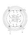
図1は本発明に係る基板処理装置の一実施例の概略構成を示した縦断面図、図2は回転支持板に基板が載置された状態を示した平面図である。
この基板処理装置100は、矩形状のガラス基板(以下、単に「基板」という)Wを保持する回転支持板31を備えている。この基板Wは、例えば縦横長さが850mm×1000mmで、厚みが0.7mmの大形で薄い基板である。回転支持板31は、基板と同等以上の大きさを有する平面視で円形の板材で形成されている。具体的には、回転支持板31の直径は基板Wの対角長さよりも長くなっており、本実施例ではその直径が約1500mmである。回転支持板31は円形状のものに限らず、角形の基板Wに合わせた矩形状であってもよいが、基板Wから飛散した洗浄液のミストが回転中の回転支持板31などに再付着するのを防止する上で、円形状が好ましい。
【0027】
回転支持板31は、その重量を軽くするために、厚さが1mm程度の薄いステンレス鋼板で形成されている。そして、大形の基板Wを後述する上部回転板32が載置されたときに、回転支持板31が鉛直方向に撓まないようにするために、絞り込み加工が施されている。
【0028】
具体的には回転支持板31は、回転中心側から半径方向外側に向けてせりあがった傾斜部31aを備えている。回転支持板31は、その傾斜部31aの外側がリング状の平坦部31bになっており、この平坦部31bに、基板Wの周縁に係合して回転力を基板Wに伝える8個の駆動ピン33が立設されている。さらに平坦部31bの外側の外周部31cは下向きに傾斜している。外周部31cの先端31dは内側へ絞り込み加工が施され、回転支持板31が鉛直方向に撓まないようにしている。このような傾斜部31a等を備えることにより、回転支持板31を厚い板材で形成することなく、その撓み剛性を簡単に向上させることができる。
【0029】
回転支持板31には、基板Wを下面から支える複数本、本実施例では図2に示すように12本の支持ピン34が立設されている。支持ピン34は回転中心P側に回転中心Pの周りに円形状(図2中に鎖線で示す)に4本、基板W周縁側に8本が配置される。これらの駆動ピン33および支持ピン34は、基板Wの中心部が低く、かつ基板Wが滑らかに湾曲した状態で支えられるように、各々の高さが調節されている。本実施例では基板Wの中心部が外周縁部に比べて4mm程度低くなっている。因みに、大形の薄い角形基板Wを完全に水平に支持するには多数の支持ピン34が必要であり、また、精度上の限界から困難を伴い、基板Wが局所的に波打った状態で支持されやすい。このような状態で基板Wを高速回転させると基板Wが振動するという不都合が生じる。本実施例では、上記のように基板Wを滑らかに湾曲した状態で支持することにより、基板Wの局所的な波打ち(凹凸)を無くし、基板Wを高速回転させたときの基板Wの振動を抑制している。
【0030】
回転支持板31の回転中心部には開口(気体噴出口)35が設けられている。この開口35に連通するように、回転支持板31の下面に筒軸36が連結接続されている。この筒軸36はベルト機構37を介してモータ38に連結されている。このモータ38は本発明において回転駆動手段として機能する。筒軸36の中心に沿って液ノズル39が配設されており、この液ノズル39の先端が基板Wの下面中心部に臨んでいる。液ノズル39は開閉弁40を介して純水などの洗浄液を供給する洗浄液供給源に接続されている。また、筒軸36と液ノズル39との間隙は大気圧雰囲気に開放されるよう構成されている。
【0031】
図3に示すように、筒軸36は回転支持板31の開口35に臨んで延在し、回転支持板31より上側に位置する側面にエアーを排出するための排出口36aが開口される。また、筒軸36の上面は液ノズル39が延出するように設けられ、この液ノズル39の側面と筒軸36の間隙である排出口36bからも大気圧雰囲気からのエアーが吐出される。そして、液ノズル39の先端部には、中央部が開口した傘状部材42が嵌め付け固定されている。この傘状部材42によって排出口36bが覆われている。
【0032】
この構成により、回転支持板31が回転するとその遠心力で排出され、回転中心Pに近いほど低圧状態となる。そのため、大気圧雰囲気に開放されている筒軸36と液ノズル39との間隙からポンプ効果によりエアーを吸入する。このエアーは、前述の排出口36a、36bより排出される。
【0033】
さらに、傘状部材42を覆うように、中央が開口した円錐台状のカバー部材44が傘状部材42に近接して配備されている。カバー部材44は筒軸36の上面に支持されて、筒軸36と一体回転するようになっている。カバー部材44の基部周面には、排出口36bから噴出したエアーを流通させるための流通孔44aが開けられている。
【0034】
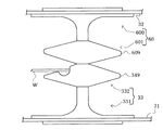
基板Wを挟んで回転支持板31に対向するように上部回転板32が配設されている。この上部回転板32は基板Wの周縁領域を覆うリング状を呈しており、中央部に直径が約600mm程度の大きな開口32aが開けられている。この開口32aには中央に円形の開口320が設けられた、いわゆるパンチングプレートよりなる流路抵抗部材321が設置してある。そして開口32aの周囲は仕切壁322が立設されている。
【0035】
上部回転板32は半径方向外側に向けて下り傾斜となった傾斜部32bを備え、この傾斜部32bのさらに外側の外周部32cが下方に屈曲して回転支持板31の外周部31cに対向している。回転支持板31の外周部31cと上部回転板32の外周部32cとの間隙は半径方向外側に向けて狭くなっており、その間隙の外周縁であるリング状の排出口45からエアーや基板Wから振り切られた洗浄液が排出されるようになっている。排出口45は下向きに傾斜した状態で配設されている。上述したような回転支持板31と上部回転板32で挟まれた空間は、基板Wを処理する処理空間Sを構成している。
【0036】
さらに上部回転板32の傾斜部32bの上面には、上方に張り出したT字状の係合部46が設置され、係合部46の上部鍔部46aに昇降駆動部47が連結されている。この昇降駆動部47はシリンダー47aのロッド47bが伸縮することでアームバー47cが昇降する。アームバー47cの下面には上述の係合部46に対向して門形アーム47dが配置され、係合部46の上部鍔部46aが係合される。この構成で門形アーム47dが上部鍔部46aに当接して上下動することにより、回転支持板31に支持される処理位置と、基板Wの搬入・搬出を許容する上方の退避位置とにわたって上部回転板32が移動するようになっている。尚、図1では、2つの昇降駆動部47が開示されているが、上部回転板32の上面に等間隔に4つの係合部46が配置され、それに対応して4つの昇降駆動部47が配置される。そして上部回転板32の回転停止位置の制御により、係合部46と門形アーム47dが係合される。
【0037】
上部回転板32の上側に、上部回転板32とは別体の流路抵抗部材48が配設されている。この流路抵抗部材48は、例えばステンレス鋼板に多数の小孔を開けた、いわゆるパンチングプレートであって、ドーナツ状に形成される。そしてその内側縁には仕切壁48aが、外側縁には仕切壁48bが下方に延在して構成される。仕切壁48aは仕切壁322の外周面に近接しており、仕切壁48bはその下端が後述する排気カップ50の上端に当接される。そして仕切壁48bの内面には昇降駆動部47のアームバー47cが連結される。また仕切壁48bの外面には装置100の枠体101に形成された搬入口101aが臨むように構成される。
【0038】
この構成により、昇降駆動部47の昇降により流路抵抗部材48は上部回転板32との位置関係を保ちながら上下動する。それに伴い仕切壁48bの下端が排気カップ50から離間して、その部位が枠体101の搬入口101aに臨むことにより装置100に基板Wを外部から搬入する搬入口として機能することとなる。即ち、仕切壁48bの下端と排気カップ50上端の間隔が搬入口であり、搬入口101aの蓋として仕切壁48bが機能していることとなる。
【0039】
装置100の上部を略閉塞するよう配設され流路抵抗部材48、321は、後述する排気構造を介した排気に伴う負圧に応じて、上部回転板32の上方から引き込まれるエアー(気流)の流れに抵抗を与えて、処理空間S内に供給されるエアーの流量を制限する役目を担っている。流路抵抗部材48、321は本実施例のようなパンチングプレートに限らず、例えば複数枚の板材を鉛直方向に傾斜させて近接配置したものであってもよく、好ましくは、このような板材の傾斜角度を変えることにより、流路抵抗を可変するようにしてもよい。
【0040】
流路抵抗部材321の開口320には、開口320を介して処理空間S内に挿入されて基板Wの上面に純水などの洗浄液を供給する液ノズル49が上下移動自在に設けられている。
【0041】
本実施例装置100の排気構造について説明する。回転支持板31と上部回転板32との間隙の外周端である排出口45に臨んで開口したリング状の排気カップ50が配設されている。この排気カップ50は、回転支持板31の下方で回転支持板31の回転半径方向内側へ絞り込まれて、回転支持板31の回転軸(本実施例では筒軸36)と平行して配置される排気管51に繋がり、この排気管51を介して装置外の排気手段に連通している。また、排気カップ50の底部外周側には、エアーとともに排出された洗浄液を排出するための排液管52が連通接続されている。
【0042】
本実施例の駆動ピン33の構成を図4(a)および図4(b)を参照して説明する。上述したように駆動ピン33は、基板Wの周縁に係合して回転支持板31の回転力を基板Wに伝える。図2に示すように、本実施例装置100は、回転支持板31の回転中心Pの周りに円形状(図2中に鎖線で示す)に配置された8個の駆動ピン33を備えている。8個の駆動ピン33はそれぞれ対になって基板Wの4つの角部周縁に係合する。
【0043】
駆動ピン33は押えピン60とで上下に分離可能に構成されている。駆動ピン33は、錘台状のピン支持部331とピン保持部332とが連結した、いわゆる茸形状を呈し、回転支持板31上面に固定して取り付けられている。ピン保持部332は断面略菱形の円盤状に形成された保持部333と、その上面の中心に係合突起334を設けてなる。
【0044】
保持部333の傾斜上面335には凹部336と、これに連なる突起337とが形成されており、基板Wの下面周縁を突起337で支持するようになっている。また、凹部336は、基板Wの側面周縁を突起338で当接し規制するようになっている。これら突起337、338は凸状の曲面に形成され、基板Wの周縁に対して点接触することで基板Wにかかる応力が不均一になることを防止している。尚、突起337は傾斜上面335を削ることによる曲率を持った縁部で形成されている。ここで、この曲面を出来る限り大きい半径でもって形成するとで、必要以上の応力が一個所に集中することを防止するうえで効果がある。
【0045】
ピン支持部331は円盤状のフランジ部340と、その上面にフランジ部340と保持部333の中心を連結し保持部333を支持する支柱部341を設けてなる。フランジ部340はその下面全体が回転支持板31の上面に当接して配置される。そのため基板Wと駆動ピン33の重みをそのフランジ部340で分散して回転支持板31と共に受けることとなる。そこで平面視でその大きさが少なくとも支柱部341の投影面積より大きく、好ましくは保持部333の投影面積より大きく形成される。そして回転支持板31が薄板で湾曲しやすくとも、このフランジ部340で回転支持板31の湾曲を防ぐこととなる。尚、駆動ピン33が本発明における駆動部材に相当する。
【0046】
一方、押えピン60も、錘台状のピン支持部600とピン押え部601とが連結した、いわゆる逆茸形状を呈し、上部回転板32下面に固定して取り付けられている。ピン押え部601は断面略菱形の円盤状に形成された押え部602と、その下面の中心に嵌合孔603を設けてなる。ピン支持部600は上部のフランジ部604と支柱部605で構成され、フランジ部604で上部回転板32に配設される。ここで、フランジ部604はフランジ部340と同様の目的で形成されている。
【0047】
そして、駆動ピン33は回転支持板31に、押えピン60は上部回転板32に、それぞれ板342、606とともにネジにより締結され固定されている。そして上部回転板32がアームバー47cによって処理位置まで下降移動されたときに、駆動ピン33の係合突起334が押えピン60の嵌合孔603に嵌合することにより、上部回転板32が回転支持板31と一体回転可能に回転支持板31に支持されるようになっている。つまり、駆動ピン33は、上部回転板32を回転支持板31に着脱自在に支持する支持機構を兼ねている。また、この押えピン60の押え部602が基板Wの浮き上がりを防止する。
【0048】
尚、駆動ピン33と押えピン60のピン支持部331、600はステンレス鋼、保持部333と押え部602とはPEEKにて形成されている。
【0049】
上記構成の駆動ピン33と押えピン60であれば、基板Wの回転処理のときに基板Wの周縁部を支持して上下に円盤形の保持部333と押え部602で構成しているので、処理空間Sから排出される洗浄液やエアーの流通を妨げず、基板Wの下面周縁の乾燥を促進させる。また、保持部333と押え部602にそれぞれ形成されている錘状部位の傾斜面は、基板Wの回転処理のときに駆動ピン33に当たるエアーを凹部336に案内して基板Wの周縁に導くことにより、基板Wの周縁の乾燥を促進させる。
【0050】
また、上記構成の駆動ピン33と押えピン60であれば、保持部333と押え部602は細い支柱部341、605で支持しているので、処理空間Sから排出される洗浄液や、エアーやミストの流通に対して大きな抵抗とならない。
【0051】
さらに、図2に示すように駆動ピン33と押えピン60を同じ円形のラインに沿って配置することにより、回転支持板31が回転したときに、それぞれの駆動ピン33と押えピン60が同じ円形軌道を移動するので、各ピンの移動に起因した気流の乱れが少なくなり、それだけ基板Wの処理を安定して行うことができる。
【0052】
次に上述した構成を備えた実施例装置の動作を順に説明する。
乾燥処理の対象である角形基板Wが本実施例装置に搬入されるとき、上部回転板32および液ノズル49は上方の退避位置にある。上部回転板32が退避位置にある状態で、駆動ピン33と押えピン60は上下に分離されており、回転支持板31上には駆動ピン33だけがある。仕切壁48bも退避位置にあり搬入口101aを介して図示しない基板搬送ロボットで搬送されてきた基板Wは、駆動ピン33のピン保持部332の保持部333によって受け持ち支持される。基板Wが搬入されると、退避位置にあった上部回転板32および液ノズル49が処理位置にまで下降移動する。上部回転板32が下降移動することにより、上部回転板32の押えピン60が回転支持板31の駆動ピン33に嵌合連結される(図1の状態)。この状態で、基板Wは回転中心部が低くなるように滑らかに湾曲した状態で支持される。
【0053】
次にモータ38が始動して回転支持板31が回転する。回転支持板31の回転力が駆動ピン33を介して基板Wに伝達されて、基板Wが回転支持板31とともに回転する。さらに、回転支持板31の回転力は押えピン60を介して上部回転板32に伝達され、上部回転板32も回転支持板31とともに回転する。このとき、回転支持板31側の液ノズル39から純水などの洗浄液が、エアーが排出口36a、36bから、それぞれ噴出される。
【0054】
また、排気管51、51に連通する装置外の排気手段が作動して排気カップ50が排気されることにより、上部回転板32の上方からエアーが流路抵抗部材48、321を介して処理空間S内へ引き込まれる。上下の液ノズル49、39から予め決められた短い時間だけ洗浄液を噴出すると、後は洗浄液の供給が停止されて、処理空間Sにはエアーだけが供給される。このように本実施例では、乾燥処理の初めの短い時間だけ洗浄液を基板Wに供給して基板Wの表裏面を洗浄液で再度濡らすことにより、基板Wの搬入時に既に付着している洗浄液によって基板Wにウォーターマークが形成されないようにしている。
【0055】
洗浄液の供給が停止された後は、回転支持板31が高速回転駆動されることにより、基板Wに付着した洗浄液が振り切られる。基板Wから振り切られた洗浄液のミストはエアーの流れに乗って処理空間S内を半径方向外側に流動し、回転支持板31と上部回転板32の間隙の外周縁である排出口45から排出される。排出された洗浄液のミストを含むエアーは排気カップ50および排気管51、51を介して装置100外へ排出される。
【0056】
また、回転支持板31と上部回転板32との間隙(処理空間S)は外周端側で絞られて、その上下の間隔が回転中心側のそれよりも狭くなっているので、排出口45からのエアーの排出量が規制される。これに合わせて、回転支持板31側から処理空間S内へ供給されるエアーの量も図示しない流量調整弁によって調整され、また、上部回転板32側から処理空間S内へ供給されるエアーの量は流路抵抗部材48、321によって規制されるので、エアーの消費量を低減することができる。処理空間S内へ供給されるエアーの量が少なくても、処理空間Sが外周端側で絞り込まれているので、エアーは処理空間Sの外周側で流速が速くなり、排出口45から勢いよく排出される。したがって、排出口45から排出された洗浄液のミストが排出口45から侵入して基板Wを汚染することもない。
【0057】
この際、駆動ピン33と押えピン60は排出されるミストに対して抵抗となるが、その主体となる部位が断面略菱形の円盤状であるためミストの流通を妨げることがなく、良好なミストの排出が行われる。
【0058】
基板Wの乾燥処理が終わると、上部回転板32および液ノズル49が退避位置に戻されて、図示しない基板搬送ロボットによって処理済の基板Wが装置外へ搬出される。以下、上述したと同様に未処理の基板Wが搬入されて処理が繰り返し行われる。
【0059】
なお、本実施例の流路抵抗部材48は次のような効果も奏する。
仮に流路抵抗部材48が配設されておらず、上部回転板32の中心部の開口32aに対向して開放されていると、基板Wの上面に大気圧が作用する。一方、回転支持板31の高速回転に伴って基板Wの下方の処理空間Sは負圧になる。その結果、基板Wの上下面の差圧に相当する圧力が基板Wの上面に作用する。基板Wは大形の薄いガラス基板であるので、この圧力によって破損されるおそれがある。これに対して、本実施例によれば上部回転板32の開口32aに対向して流路抵抗部材321を介在させることにより、処理空間Sへ流入するエアーの量を規制している。その結果、基板Wの上方の処理空間Sも負圧になり、基板Wの上下面の差圧が小さくなる。したがって、基板Wの破損を防止することができる。
【0060】
傘状部材42を覆うカバー部材44は次のような効果を奏する。
すなわち、傘状部材42はカバー部材44で覆われているので、液ノズル39から噴出された洗浄液の一部が落下しても、そのほとんどがカバー部材44に付着する。傘状部材42は回転しないのに対して、カバー部材44は筒軸36と一体に回転する。したがって、カバー部材44は付着した洗浄液は即座に振り切られ、カバー部材44に長く残留しないので、カバー部材44に付着した洗浄液が基板Wに再付着することもない。また、傘状部材42とカバー部材44との間隙に洗浄液が侵入したとしても、排出口36bから噴出したエアーがカバー部材44の基部にある流通孔44aを通過流通する際に、前記間隙に侵入した洗浄液を引き込んで即座に排出する。したがって、傘状部材42とカバー部材44との間隙に侵入した洗浄液もそこに長く滞在することがないので、残留洗浄液による基板Wの汚染を防止することができる。
【0061】
本発明は上述した実施例に限らず次のように変形実施することができる。
(1)上記実施例では駆動ピン33が上部回転板32の支持機構を兼ねたが、上部回転板32の支持機構を駆動ピン33とは個別に設けるようにしてもよい。
【0062】
(2)さらに、上記実施例では駆動ピン33は、図2に示すように回転支持板31の回転中心Pの周りに円形状(図2中に鎖線で示す)に8個の駆動ピン33を配置したが、これらの駆動ピン33よりも回転中心側で基板Wの周縁に係合する駆動ピンを備えるようにしてもよい。
【0063】
(3)さらに、駆動ピン33と押えピン60における保持部333と押え部602は図5に示すような形状でもよい。即ち、外周縁349、609は鋭角ではなく断面半円形である曲率を有する形状としてよい。処理液の付着を防止する上で平坦で流線形であればよく、こうすることで排出される気流により表面への処理液の付着が防止されればよい。
【0064】
(4)さらに、上記実施例ではフランジ部340、604を平坦に形成しているが、図6に示すように、尚、図6では押えピン60のフランジ部のみを断面図示するが駆動ピン33も同じ構成をとる、上部回転板32へのネジ70による締結部位の外周を上部回転板32側に突出されて構成してもよい。図6では、締結部位をその外周とで段差71を有する形状とする。こうすることによりネジ70を締め付けると締結部位ではフランジ部72と上部回転板32との当接には余裕があるが、その外周部ではすでに当接しており、その当接力が強くなることとなる。よって、フランジ部72の外周部が上部回転板32から浮き上がることを防止でき、それに伴って基板Wの支持が不安定になることが防止される。また、フランジ部の形状は、締結部位を上方に位置するように緩やかに湾曲した形状としてもよい。
【0065】
(5)さらに、上記実施例では処理空間Sを大気雰囲気に開放してエアーが流入するように構成したが、窒素ガス等の不活性ガスを供給するように構成してもよい。こうすることにより基板Wの洗浄処理後の乾燥処理においてウォーターマークの発生を一層防止することができる。
【0066】
【発明の効果】
以上説明したように、本発明によれば、基板を保持して良好に処理することができる基板処理装置が提供される。即ち、基板に回転力を伝える複数個の駆動部材は、断面略菱形の円盤形状で、その傾斜上面で前記基板を支持し水平位置を規制するとともに基板に回転力を伝える。この形状により遠心力により排出される処理液、エアーやミストは駆動部材の部位でその流速が衰えることがない。よって、特に処理液は円盤形状の表面上をすりぬけて処理空間より排出され、駆動部材に付着滞留することがない。また、回転支持板に支柱を介してフランジ部にて駆動部材が設置され、そのフランジ部は平面視で支柱より大きく構成されている。即ち、フランジ部で駆動部材の重みを分散して回転支持板に負荷がかかるようにすることで、基板を保持することによる重みで回転支持板が変形することを防止する。さらに、フランジ部は回転支持板への締結部位の外周を回転支持板側に突出されている。即ち、フランジ部は薄い平板状で大きくなるほど締結部位から離れる端部が浮き上がるが、締結部位の外周を締結部位より突出させることにより強く回転支持板に当接して、フランジ部の外周が回転支持板から浮き上がるのを防止できる。
【図面の簡単な説明】
【図1】本発明に係る基板処理装置の一実施例の概略構成を示した縦断面図である。
【図2】回転支持板に基板を支持した状態を示す平面図である。
【図3】回転支持板側の液ノズルの周辺構成を示した拡大断面図である。
【図4】駆動ピンと押えピンの構成を示し、(a)は断面図、(b)は駆動ピンの構成を示した斜視図である。
【図5】他の実施例に係る駆動ピンと押えピンの外観図である。
【図6】他の実施例に係る駆動ピンと押えピンの一部断面外観図である。
【図7】従来装置の概略構成を示した縦断面図である。
【図8】従来の駆動ピンの構成示した図で、(a)はその側面図で(b)は全体斜視図である。
【符号の説明】
W 基板
S 処理空間
100 基板処理装置
1、31 回転支持板
7、32 上部回転板
2、33 駆動ピン
60 押えピン
321、605 ピン支持部
340、604、72 フランジ部
341、605 支柱部
333 保持部
335 傾斜上面
336 凹部
6、10、39、49 液ノズル
3、36 筒軸
48、321 流路抵抗部材[0001]
BACKGROUND OF THE INVENTION
The present invention relates to a substrate processing apparatus for performing required processing such as cleaning processing and drying processing while rotating a substrate such as a glass substrate or a semiconductor wafer for a liquid crystal display in a horizontal plane, particularly for processing a large substrate. The present invention relates to a substrate processing apparatus suitable for the above.
[0002]
[Prior art]
As a conventional substrate processing apparatus of this type, an apparatus disclosed in, for example, Japanese Patent Application Laid-Open No. 9-330904 will be described with reference to FIG.
This substrate processing apparatus is an apparatus that performs chemical treatment, cleaning treatment, and drying treatment on the front and back surfaces of the substrate W in that order while rotating the substrate W such as a semiconductor wafer in a horizontal plane. The substrate processing apparatus includes a
[0003]
An opening 1a is provided at the center of rotation of the
[0004]
An upper rotary plate 7 is disposed so as to face the
[0005]
Further, a cup 11 is disposed so as to surround the
[0006]
8A and 8B are diagrams for explaining the configuration of the
[0007]
In the substrate processing apparatus configured as described above, the substrate processing is performed as follows.
First, the substrate W is placed on the
[0008]
As described above, the substrate W is processed in the flat processing space S defined by the
[0009]
[Problems to be solved by the invention]
However, the conventional example having such a configuration has the following problems. That is, in the conventional apparatus shown in FIG. 7, the chemical liquid or the cleaning liquid discharged by the centrifugal force from the processing space S against the
[0010]
Depending on the shape of the
[0011]
Furthermore, with the recent increase in the diameter of a substrate such as a semiconductor wafer, the
[0012]
The present invention has been made in view of such circumstances, and in a substrate processing apparatus that performs processing by rotating a substrate, the processing mechanism is optimized and also when a large substrate is processed. The main object is to provide a substrate processing apparatus capable of reducing the contamination of the processing mechanism as much as possible.
[0013]
[Means for solving the problems and their functions and effects]
In order to achieve the above object, the present invention provides a substrate processing apparatus for performing processing by supplying a processing liquid to a substrate while rotating the substrate, and rotating the substrate while supporting the substrate in a horizontal posture. The rotation support plate of the same size or larger and the rotation support plateErectedA plurality of driving members that engage with the outer peripheral edge of the substrate to regulate the horizontal position of the substrate and transmit the rotational force to the substrate;AndThe driving member has a disk shape having a substantially rhombus cross section and a holding portion that supports the substrate on its inclined upper surface.Further, the driving member is installed on the rotating support plate through a support column with a flange portion larger than the support column in a plan view, and the flange portion has an outer periphery of a fastening portion to the rotating support plate protruding toward the rotating support plate side. IsA substrate processing apparatus.
[0014]
According to a second aspect of the present invention, in the substrate processing apparatus according to the first aspect of the present invention, a disc-shaped pressing member having a substantially rhombic cross section is disposed above the driving member.According to a third aspect of the present invention, in the substrate processing apparatus according to the second aspect of the present invention, the substrate processing apparatus includes a ring-shaped upper rotating plate that is disposed to face the rotating support plate with the substrate interposed therebetween and covers a peripheral region of the substrate. The pressing member is disposed at a portion of the upper rotating plate facing the driving member, and the driving member also serves as a support mechanism for detachably supporting the upper rotating plate on the rotating support plate via the pressing member. It is characterized by.
[0015]
In order to achieve the above object, the present invention provides a substrate processing apparatus for performing processing by supplying a processing liquid to a substrate while rotating the substrate, and rotating the substrate while supporting the substrate in a horizontal posture. A rotation support plate having the same or larger size, and a plurality of drive members that are erected on the rotation support plate and engage the outer peripheral edge of the substrate to regulate the horizontal position of the substrate and transmit the rotational force to the substrate. The drive member is formed in a disk shape having a substantially rhombic cross section, and includes a holding portion that supports the substrate. The inclined upper surface of the holding portion includes a concave portion formed by scraping the inclined upper surface, and is connected thereto. The substrate processing apparatus is characterized in that a protrusion is formed and a side surface periphery of the substrate is abutted and regulated by the protrusion.
[0016]
According to a fifth aspect of the present invention, in the substrate processing apparatus according to the fourth aspect of the present invention, the projection that continues to the concave portion is formed in a convex curved surface.
[0017]
The invention according to
[0018]
The operation of the present invention is as follows. In the substrate processing apparatus according to the first aspect, the substrate can be processed satisfactorily. ImmediatelyISeveral drive members are disks with a roughly diamond-shaped cross sectionOn the inclined upper surface of the holding partSupports the substrate, regulates the horizontal position, and transmits rotational force to the substrate. With this shape, the flow rate of the processing liquid discharged by centrifugal force does not decrease at the site of the driving member. This is because the air flow generated by the centrifugal force passes through the surface of the driving member that is streamlined and is discharged from the processing space, so that the processing liquid attached to the driving member does not stay on the driving member.Further, a driving member is installed on the rotation support plate at a flange portion via a support column. The flange portion is larger than the support in plan view. That is, the weight of the driving member is dispersed at the flange portion so that a load is applied to the rotation support plate. By doing so, the rotation support plate is prevented from being deformed by the weight due to holding the substrate. In addition, since the column supporting the driving member is smaller than the flange portion in plan view, it is possible to prevent the discharged processing liquid from adhering and staying. Further, the flange portion protrudes from the outer periphery of the fastening portion to the rotation support plate to the rotation support plate side. That is, as the flange portion is thin and flat, the end away from the fastening portion rises. Therefore, the outer periphery of the fastening part is caused to protrude from the fastening part to be brought into strong contact with the rotation support plate. This can prevent the outer periphery of the flange portion from floating from the rotation support plate.
[0019]
According to a second aspect of the present invention, a presser member having a substantially diamond-shaped cross section and a disk shape is disposed above the drive member. According to the present invention, it is possible to provide a substrate processing apparatus that can prevent the substrate held by the driving member from being lifted, and as a result, can prevent the substrate from being detached from the driving member. Moreover, since the shape of the pressing member is also a disk shape, adhesion and retention of the processing liquid can be prevented.
[0020]
By the way, the floating of the substrate will be described with reference to FIG. The center of gravity of the substrate W sandwiched between the drive pins 2 is not necessarily located on the central axis of the
[0021]
Further, when the jetting power of the processing liquid discharged from the
[0022]
According to invention of Claim 3,The drive member erected on the rotation support plate for transmitting the rotational force to the substrate also serves as a support mechanism for the upper rotation plate, so that it is not necessary to provide a separate mechanism for supporting the upper rotation plate on the rotation support plate. As a result, since the turbulence of the airflow when the rotary support plate rotates is also minimized, the substrate processing is stabilized.
[0023]
According to the invention of
[0024]
Claim 5According to the described invention,The protrusion connected to the concave portion is formed in a convex curved surface and can prevent the stress applied to the substrate from becoming non-uniform by making point contact with the peripheral edge of the substrate.
[0025]
DETAILED DESCRIPTION OF THE INVENTION
Embodiments of the present invention will be described below with reference to the drawings.
Here, the substrate processing apparatus used for the drying process of the glass substrate for liquid crystal displays will be described as an example. However, the present invention can be applied not only to processing of glass substrates but also to processing of various substrates such as semiconductor wafers. In addition, the substrate processing to which the present invention can be applied is not limited to a drying process, but also includes a chemical process and a cleaning process. Furthermore, the device of the present invention is not limited to a device that performs a single process, but a device that performs a chemical treatment, a cleaning process, and a drying process continuously in the same apparatus, and a cleaning process and a drying process in the same apparatus. It can also be applied to things that are performed continuously.
[0026]
FIG. 1 is a longitudinal sectional view showing a schematic configuration of an embodiment of a substrate processing apparatus according to the present invention, and FIG. 2 is a plan view showing a state where a substrate is placed on a rotation support plate.
The
[0027]
The
[0028]
Specifically, the
[0029]
The
[0030]
An opening (gas ejection port) 35 is provided at the center of rotation of the
[0031]
As shown in FIG. 3, the
[0032]
With this configuration, when the
[0033]
Furthermore, a
[0034]
An upper
[0035]
The upper
[0036]
Further, a T-shaped engaging
[0037]
On the upper side of the upper rotating
[0038]
With this configuration, the flow
[0039]
The flow
[0040]
A
[0041]
The exhaust structure of the
[0042]
The configuration of the
[0043]
The
[0044]
A
[0045]
The
[0046]
On the other hand, the
[0047]
The
[0048]
The
[0049]
In the case of the
[0050]
Further, in the case of the
[0051]
Furthermore, as shown in FIG. 2, by arranging the
[0052]
Next, the operation of the embodiment apparatus having the above-described configuration will be described in order.
When the rectangular substrate W to be dried is carried into the apparatus of this embodiment, the upper rotating
[0053]
Next, the
[0054]
Further, when the exhaust means outside the apparatus communicating with the
[0055]
After the supply of the cleaning liquid is stopped, the cleaning liquid adhering to the substrate W is shaken off by rotating the
[0056]
Further, the gap (processing space S) between the
[0057]
At this time, the
[0058]
When the drying process of the substrate W is completed, the upper rotating
[0059]
In addition, the flow
If the flow
[0060]
The
That is, since the umbrella-shaped
[0061]
The present invention is not limited to the embodiment described above, and can be modified as follows.
(1) In the above embodiment, the
[0062]
(2) Further, in the above-described embodiment, the drive pins 33 have eight drive pins 33 in a circular shape (indicated by a chain line in FIG. 2) around the rotation center P of the
[0063]
(3) Further, the holding
[0064]
(4) Further, in the above embodiment, the
[0065]
(5) Further, in the above-described embodiment, the processing space S is opened to the atmosphere and air is introduced. However, an inert gas such as nitrogen gas may be supplied. By doing so, it is possible to further prevent the generation of watermarks in the drying process after the cleaning process of the substrate W.
[0066]
【The invention's effect】
As described above, according to the present invention, there is provided a substrate processing apparatus capable of holding a substrate and processing it satisfactorily. That is, the plurality of driving members that transmit the rotational force to the substrate have a substantially diamond-shaped disk shape, support the substrate on the inclined upper surface, restrict the horizontal position, and transmit the rotational force to the substrate. With this shape, the processing liquid, air, and mist discharged by centrifugal force does not decrease in flow velocity at the drive member. Therefore, in particular, the processing liquid passes through the disk-shaped surface and is discharged from the processing space, and does not adhere and stay on the driving member.In addition, a drive member is installed at the flange portion through the support on the rotation support plate, and the flange is configured to be larger than the support in plan view. That is, by distributing the weight of the drive member at the flange portion so that the load is applied to the rotation support plate, the rotation support plate is prevented from being deformed by the weight due to holding the substrate. Furthermore, the flange part protrudes the outer periphery of the fastening site | part to a rotation support plate to the rotation support plate side. That is, the flange part is a thin flat plate, and as the size increases, the end away from the fastening part rises, but by making the outer periphery of the fastening part protrude from the fastening part, the outer periphery of the flange part strongly contacts the rotational support plate. Can be prevented from floating up.
[Brief description of the drawings]
FIG. 1 is a longitudinal sectional view showing a schematic configuration of an embodiment of a substrate processing apparatus according to the present invention.
FIG. 2 is a plan view showing a state in which a substrate is supported on a rotation support plate.
FIG. 3 is an enlarged cross-sectional view showing a peripheral configuration of a liquid nozzle on the rotation support plate side.
4A and 4B show a configuration of a drive pin and a presser pin, in which FIG. 4A is a cross-sectional view and FIG. 4B is a perspective view showing a configuration of a drive pin.
FIG. 5 is an external view of a drive pin and a presser pin according to another embodiment.
FIG. 6 is a partial sectional external view of a drive pin and a presser pin according to another embodiment.
FIG. 7 is a longitudinal sectional view showing a schematic configuration of a conventional apparatus.
8A and 8B are diagrams showing a configuration of a conventional drive pin, in which FIG. 8A is a side view and FIG. 8B is an overall perspective view.
[Explanation of symbols]
W substrate
S processing space
100 Substrate processing equipment
1, 31 Rotating support plate
7, 32 Upper rotating plate
2, 33 Drive pin
60 Presser pin
321, 605 pin support
340, 604, 72 Flange
341, 605 support
333 holding part
335 inclined top surface
336 recess
6, 10, 39, 49 Liquid nozzle
3, 36 Tube shaft
48,321 Channel resistance member
Claims (6)
基板を水平姿勢で支持した状態で回転駆動する、基板と同等以上の大きさの回転支持板と、
前記回転支持板に立設され、基板の外周端縁に係合して前記基板の水平位置を規制するとともに基板に回転力を伝える複数個の駆動部材と
を備え、
前記駆動部材は、断面略菱形の円盤形状でその傾斜上面で前記基板を支持する保持部を備え、
さらに、前記駆動部材は前記回転支持板に支柱を介して平面視で支柱より大きなフランジ部にて設置され、
前記フランジ部は前記回転支持板への締結部位の外周が回転支持板側に突出されている
ことを特徴とする基板処理装置。A substrate processing apparatus for performing processing by supplying a processing liquid to a substrate while rotating the substrate,
A rotation support plate having a size equal to or greater than that of the substrate, which is rotationally driven in a state where the substrate is supported in a horizontal posture;
A plurality of driving members which are erected on the rotation support plate, engage a peripheral edge of the substrate to regulate the horizontal position of the substrate and transmit a rotational force to the substrate ;
With
The drive member includes a holding portion that supports the substrate on the inclined upper surface in a disk shape having a substantially rhombic cross section ,
Furthermore, the drive member is installed on the rotation support plate with a flange portion larger than the support in plan view through the support,
2. The substrate processing apparatus according to claim 1, wherein the flange portion has an outer periphery of a fastening portion to the rotation support plate protruding toward the rotation support plate .
前記駆動部材の上部に断面略菱形で円盤形状の押え部材を配置する基板処理装置。The substrate processing apparatus according to claim 1,
A substrate processing apparatus in which a pressing member having a substantially diamond shape and a disk shape is disposed on an upper portion of the driving member.
前記基板を挟んで前記回転支持板に対向して配置され、基板の周縁領域を覆うリング状の上部回転板を有し、この上部回転板の前記駆動部材に対向する部位に前記押え部材を配置し、前記駆動部材は前記上部回転板を前記押え部材を介して前記回転支持板に着脱自在に支持する支持機構を兼ねている基板処理装置。It has a ring-shaped upper rotating plate that is disposed opposite to the rotation support plate across the substrate and covers the peripheral area of the substrate, and the pressing member is disposed at a portion of the upper rotating plate that faces the driving member. The drive member also serves as a support mechanism that detachably supports the upper rotary plate on the rotary support plate via the pressing member.
基板を水平姿勢で支持した状態で回転駆動する、基板と同等以上の大きさの回転支持板と、A rotation support plate having a size equal to or greater than that of the substrate, which is driven to rotate while the substrate is supported in a horizontal posture;
前記回転支持板に立設され、基板の外周端縁に係合して前記基板の水平位置を規制するとともに基板に回転力を伝える複数個の駆動部材とA plurality of driving members which are erected on the rotation support plate, engage a peripheral edge of the substrate to regulate the horizontal position of the substrate and transmit a rotational force to the substrate;
を備え、With
前記駆動部材は、断面略菱形の円盤状に形成され、基板を支持する保持部を備え、The drive member is formed in a disk shape having a substantially diamond-shaped cross section, and includes a holding portion that supports the substrate,
前記保持部の傾斜上面には、該傾斜上面を削ることによる凹部と、これに連なる突起とが形成され、前記基板の側面周縁を前記突起で当接し規制するOn the inclined upper surface of the holding portion, a concave portion formed by cutting the inclined upper surface and a projection connected to the concave portion are formed, and the peripheral edge of the side surface of the substrate is abutted and regulated by the projection.
ことを特徴とする基板処理装置。A substrate processing apparatus.
前記凹部に連なる突起は、凸状の曲面に形成される基板処理装置。The substrate processing apparatus, wherein the protrusion connected to the concave portion is formed in a convex curved surface.
前記基板は矩形状のガラス基板である基板処理装置。The substrate processing apparatus, wherein the substrate is a rectangular glass substrate.
Priority Applications (1)
| Application Number | Priority Date | Filing Date | Title |
|---|---|---|---|
| JP2000127281A JP3748028B2 (en) | 2000-04-27 | 2000-04-27 | Substrate processing equipment |
Applications Claiming Priority (1)
| Application Number | Priority Date | Filing Date | Title |
|---|---|---|---|
| JP2000127281A JP3748028B2 (en) | 2000-04-27 | 2000-04-27 | Substrate processing equipment |
Publications (2)
| Publication Number | Publication Date |
|---|---|
| JP2001300400A JP2001300400A (en) | 2001-10-30 |
| JP3748028B2 true JP3748028B2 (en) | 2006-02-22 |
Family
ID=18636906
Family Applications (1)
| Application Number | Title | Priority Date | Filing Date |
|---|---|---|---|
| JP2000127281A Expired - Fee Related JP3748028B2 (en) | 2000-04-27 | 2000-04-27 | Substrate processing equipment |
Country Status (1)
| Country | Link |
|---|---|
| JP (1) | JP3748028B2 (en) |
Families Citing this family (8)
| Publication number | Priority date | Publication date | Assignee | Title |
|---|---|---|---|---|
| JP3989384B2 (en) * | 2003-02-07 | 2007-10-10 | 東京エレクトロン株式会社 | Substrate processing apparatus and substrate processing method |
| JP4971294B2 (en) * | 2008-12-02 | 2012-07-11 | 三菱電機株式会社 | Substrate processing apparatus, substrate processing method, and display device manufacturing method |
| CN102441539B (en) * | 2010-09-30 | 2013-09-18 | 承澔科技股份有限公司 | Element cleaning machine easy for flow guide |
| CN102652947B (en) * | 2011-03-02 | 2014-05-07 | 承澔科技股份有限公司 | Element cleaner |
| JP6057334B2 (en) * | 2013-03-15 | 2017-01-11 | 株式会社Screenホールディングス | Substrate processing equipment |
| US10037902B2 (en) | 2015-03-27 | 2018-07-31 | SCREEN Holdings Co., Ltd. | Substrate processing device and substrate processing method |
| JP7149815B2 (en) * | 2018-11-15 | 2022-10-07 | 川崎重工業株式会社 | Robot system and its operation method |
| CN114749305A (en) * | 2022-04-25 | 2022-07-15 | 贵州电网有限责任公司 | Derusting and spraying rotary worktable and positioning and calibrating method |
-
2000
- 2000-04-27 JP JP2000127281A patent/JP3748028B2/en not_active Expired - Fee Related
Also Published As
| Publication number | Publication date |
|---|---|
| JP2001300400A (en) | 2001-10-30 |
Similar Documents
| Publication | Publication Date | Title |
|---|---|---|
| US7722736B2 (en) | Apparatus for and method of processing a substrate with processing liquid | |
| JP3518948B2 (en) | Substrate rotation processing equipment | |
| JPH07256195A (en) | Rotary liquid chemicals treatment device | |
| JP3748028B2 (en) | Substrate processing equipment | |
| TW200836841A (en) | Substrate processing apparatus and substrate processing method | |
| TWI446418B (en) | Liquid processing device | |
| JPH07106233A (en) | Rotary type substrate treater | |
| US20080053488A1 (en) | Substrate treatment apparatus and substrate treatment method | |
| JPH11260718A (en) | Method and apparatus for development | |
| US6364547B1 (en) | Solution processing apparatus | |
| US6930046B2 (en) | Single workpiece processing system | |
| JP2906017B2 (en) | Coating device | |
| JP2019521519A (en) | Substrate support device | |
| JP3518953B2 (en) | Rotary substrate processing equipment | |
| JP3973344B2 (en) | Substrate processing equipment | |
| JP4601341B2 (en) | Substrate processing equipment | |
| JP3953248B2 (en) | Substrate processing equipment | |
| US20180067407A1 (en) | Substrate cleaning device and substrate processing apparatus including the same | |
| JPH0864568A (en) | Wafer cleaning device | |
| JPH11330041A (en) | Device for processing substrate by etching liquid | |
| JP3479602B2 (en) | Substrate processing apparatus and substrate processing method | |
| JP5143657B2 (en) | Liquid processing equipment | |
| JP3133735B2 (en) | Rotary coating device | |
| JP2002016031A (en) | Substrate treatment method | |
| JP2002177854A (en) | Substrate treatment apparatus |
Legal Events
| Date | Code | Title | Description |
|---|---|---|---|
| A977 | Report on retrieval |
Free format text: JAPANESE INTERMEDIATE CODE: A971007 Effective date: 20050622 |
|
| A131 | Notification of reasons for refusal |
Free format text: JAPANESE INTERMEDIATE CODE: A131 Effective date: 20050628 |
|
| A521 | Written amendment |
Free format text: JAPANESE INTERMEDIATE CODE: A523 Effective date: 20050819 |
|
| TRDD | Decision of grant or rejection written | ||
| A01 | Written decision to grant a patent or to grant a registration (utility model) |
Free format text: JAPANESE INTERMEDIATE CODE: A01 Effective date: 20051122 |
|
| A61 | First payment of annual fees (during grant procedure) |
Free format text: JAPANESE INTERMEDIATE CODE: A61 Effective date: 20051122 |
|
| R150 | Certificate of patent (=grant) or registration of utility model |
Free format text: JAPANESE INTERMEDIATE CODE: R150 |
|
| LAPS | Cancellation because of no payment of annual fees |