JP3936621B2 - Play-filled tension type damping structure - Google Patents
Play-filled tension type damping structure Download PDFInfo
- Publication number
- JP3936621B2 JP3936621B2 JP2002128529A JP2002128529A JP3936621B2 JP 3936621 B2 JP3936621 B2 JP 3936621B2 JP 2002128529 A JP2002128529 A JP 2002128529A JP 2002128529 A JP2002128529 A JP 2002128529A JP 3936621 B2 JP3936621 B2 JP 3936621B2
- Authority
- JP
- Japan
- Prior art keywords
- type
- joint
- filling
- brace
- damping structure
- Prior art date
- Legal status (The legal status is an assumption and is not a legal conclusion. Google has not performed a legal analysis and makes no representation as to the accuracy of the status listed.)
- Expired - Lifetime
Links
Images


Landscapes
- Buildings Adapted To Withstand Abnormal External Influences (AREA)
- Vibration Prevention Devices (AREA)
- Joining Of Building Structures In Genera (AREA)
Description
【0001】
【産業上の利用分野】
本発明は遊隙充填引張型制震構造に関しより詳しくは耐震強度に優れた露出型柱脚構造および筋かい等の金属構造であって、塑性変形によって地震エネルギを吸収する機能に優れた遊隙充填引張型制震構造に関する。
【0002】
【従来技術と課題】
従来、露出型柱脚等のコンクリート基礎鋼柱脚構造ないし筋かいは、地震被害対策の要点であり、破壊エネルギの最も集中する場所である事が判っている。
【0003】
そしてここで生じる引張応力部材であるアンカーボルトもしくは筋かい部材の引張塑性変形によって、遊隙(遊び)が生じ、早急な繰返し震動の場合、次の引張応力がかかるまでに必ず遊隙が生まれるために構造物として必要な強度が出ず、必要とする塑性域におけるエネルギ吸収が充分に行えないという問題点があった。
【0004】
従来の露出型柱脚は地震に対しアンカーボルトを降伏させ、アンカーボルトの塑性伸びのみで地震エネルギの吸収を行っている。この場合露出型柱脚の復元力特性(荷重−変形履歴曲線)はスリップ型となるが、柱脚により多くの地震エネルギを吸収させようとすると、必然に第1層において大きな層間変形角を生じる事になる。
【0005】
そしてこの荷重−変形履歴曲線上のスリップは、アンカーボルトの塑性伸びによってベースプレートとナット間に生じる遊隙によって発生する事が実例および実験観察の結果明らかになった。これらの対策としては次のようなものがあった。
【0006】
従来例としては特開平10−299081に記載の発明のように、柱脚の回転剛性を小さくするため、べースプレートとアンカーボルトナットの間に弾性バネを挿入するものがあつた。また特開2002−4422のように柱脚を角鞘状の鞘管で支持するものも提案されているが、これはアンカーボルトで固定したベースプレートを切り離し、4箇のエネルギ吸収部材である低降伏点鋼片を介して柱脚が自由に回動する事を許す手段であって、これらは、所謂ピン柱脚もしくは半固定柱脚と呼ばれるもので、本発明のように繰返し与えられる震動に対して有効な固着とはならない事が明らかである。
【0007】
即ち前記先行技術ではアンカーボルトの塑性変形で以て地震エネルギを有効に吸収する事が出来なかった。
【0008】
一方従来のアンカーボルトはネジ部で破断する事が多かったが、最近の転造ネジつきアンカーボルトではネジ部の強度が高いためこのような事がなく、シャフト部の塑性伸びを、例えば伸び率10%程度まで期待出来るようになった。加えてベースプレートについてもこれの曲げ変形を少なくし、すなわちアンカーボルトの伸び変形抵抗に比して、より変形抵抗を大きくし剛体化する事の方が地震エネルギの吸収に有効である事が判って来た。
【0009】
また筋かいの場合、特開平11−36444のように所謂アンボンドブレース(Unbond brace)があるが、これは引張と圧縮の両応力に抵抗出来るメリットがあるものの、筋かい材が断面大となると共に複雑化大型化するため、X字型筋かい構造にする事が困難となり、K字型ないしV字型筋かいを設ける必要が生じるなどの問題点があった。加えてアンボンドブレースは前記遊隙対策にはならなかった。
【0010】
そこで本発明者は、鋭意実験研究の結果この遊隙をなくす事によってスリップ現象を除去し、従来よりも層間変形角を小さくし、より大きい地震エネルギを吸収可能とする本発明に到達した。
【0011】
当初遊隙充填手段としては実験途中でアンカーボルトや筋かいのナットを増し締めする事で行って効果を確認したが、実際の建築物に応用する場合、これを自動化する必要があり、更に実験研究の結果、本発明のような自動充填機構を備える遊隙充填型制震構造と呼ぶ本発明を完成するに至った。
【0012】
すなわち本発明者は鋭意実験・研究の結果、遊隙自動充填機構を工夫、導入する事により、引張抵抗力のみを有効活用し、アンカーボルトないし筋かいの塑性域における引張変形のみで地震エネルギを吸収するようにする事が出来るようになった。また従来例では圧縮応力による座屈対策のために必要としたようなアンボンドブレースを用いる事なく圧縮側に座屈が生じず、継続的に充分引張応力に耐える筋かいを得る事が出来るようになった。
【0013】
【発明の目的】
本発明の第1の目的は、低周波振動が付与される時、先の震動によって生じる遊隙の悪影響を後の震動時に及ばなくする事である。
【0014】
本発明の第2の目的は特に建築物の鉄骨固定脚柱のモーメントに対するエネルギ吸収能を増し、また筋かいの場合も層間変形角を小さくして遊隙なく直ちに変形抵抗を発揮出来るようにする事である。
【0015】
本発明の第3の目的は荷重−変形履歴曲線が、露出型柱脚では従来のスリップ型でなくノンスリップ型(原点立上がり型)となり、筋かいでも同様に従来のスリップ型でなく、紡錘型となり、エネルギ吸収が有効に行われるようになり、また、コンピュータによる変形予測もしくは強度計算がし易くなるようにする事である。
【0016】
【発明の構成】
本発明により、
地震等の振動により、接合部が繰返し引張応力を受ける場合、アンカーボルトまたは筋かいでなる引張応力部材が塑性変形する事により該地震エネルギを吸収する引張型制震構造において、先に生じた接合部間の遊隙が、引張応力に対して略直角方向に弾性体付勢力によって挿入される挿入型楔により自動充填される自動充填機構を備え、次の引張応力が加わる時、接合部間に遊隙なく前記引張応力部材の塑性変形が開始されるようにした事を特徴とする遊隙充填引張型制震構造(請求項1)、
遊隙充填引張型制震構造の接合部が、土木建築構造における露出型柱脚のベースプレートとアンカーボルトナット間接合部もしくはX字型の筋かい端部プレートと筋かいナット間接合部である請求項1に記載の遊隙充填引張型制震構造(請求項2)、
挿入型楔の先端傾斜角θが15°≦θ≦75°である請求項2に記載の遊隙充填引張型制震構造(請求項3)、
挿入型楔を挿入する弾性体が、コイルバネ、つるまきバネ、板バネ、ゴムクッションの内1または2以上の組合せである請求項2ないし3の内いずれか1項に記載の遊隙充填引張型制震構造(請求項4)、
遊隙充填引張型制震構造の接合部が、土木建築構造における露出型柱脚のベースプレートとアンカーボルトナット間接合部であり、荷重−変形履歴曲線が常時原点立上がりとなるノンスリップ型をなす請求項1ないし4の内いずれか1項に記載の遊隙充填引張型制震構造(請求項5)
および
遊隙充填引張型制震構造の接合部が、土木建築構造におけるX字型の筋かい端部プレートと筋かいナット間接合部であり、一対の筋かいの荷重−変形履歴曲線が紡錘型をなす請求項1ないし5の内いずれか1項に記載の遊隙充填引張型制震構造(請求項6)
が提供される。
【0017】
以下に実施例を用いて本発明を詳細に説明する。
【0018】
【実施例】
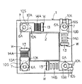
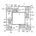
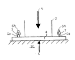
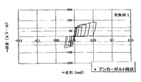
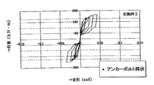
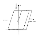
図1は震動開始前の柱脚部側面図、図2は震動1/2サイクル後の柱脚部側面図、図3は震動1サイクル後の柱脚部側面図、図4は図1のA−A矢視図、図5は図2のB−B矢視図、図6は図3のC−C矢視図、図7は挿入型楔の斜視図、図8は軸力Nと反時計廻りのモーメントMを受けた時の柱脚部側面図、図9は次に軸力Nと時計廻りのモーメントM'を受けた時の柱脚部側面図、図10は次に復元して左右アンカーボルトネジ部ナットとベースプレート間に塑性伸びによって遊隙G2,G2が生じた状況を示す柱脚部側面図、図11は一方向クラッチを用いた実施例1の側面図、図12は従来例(遊隙充填なし)(軸力Nが作用しない場合)の荷重−変形履歴グラフ、図13は実施例1(軸力Nが作用しない場合)の荷重−変形履歴グラフ、図14は従来例(遊隙充填なし)(軸力Nが作用する場合)の荷重−変形履歴グラフ、図15は実施例1(軸力Nが作用する場合)の荷重−変形履歴グラフ、図16は震動開始前の実施例2の側面図、図17は震動1サイクル後の実施例2側面図、図18は実施例2の荷重−変形履歴グラフである。
【0019】
図1〜18において、
1は実施例1、200は実施例2、2は柱脚部、4はベースプレート、6はアンカーボルト、6Aはアンカーボルトネジ部、7はナット、10,10A,10Bは夫々挿入型楔、挿入前の挿入型楔、挿入後の挿入型楔であり、10Kはボルト長孔,10Pは傾斜壁、10Sは傾斜面,11は楔受け、13はバネ受け、、G1,G2,G3は遊隙、Nは軸力、Mはモーメント、Cは圧縮反力、Vは引張反力、Wは隅肉溶接部、14Aは圧縮されたコイルバネ、14Bは伸びたコイルバネ、20はコンクリート基礎,30は一方向ベアリング、31はニードルローラ、32,33はベアリングレース、32Aは傾斜溝、34は可動リテーナ、35は押引きコイルバネである。
<実施例1>
先ず、柱脚部において、1/2サイクルだけ震動が与えられた時、
すなわち柱脚部に柱脚方向の軸力Nと反時計方向のモーメントMが掛ると柱脚部は図8のような状態となり、ベースプレート左端部を支点として左側に傾く。そしてベースプレート4の剛性が高いと右側アンカーボルト6は短い弾性変形の後降伏し、略鉛直方向の引張塑性変形を生じる。ここで震動エネルギがアンカーボルト6に吸収される事になる。同様に図9は時計方向のモーメントM'が加わる場合である。
【0020】
アンカーボルトの材質はJISG3138建築構造用圧延棒鋼のSNR400A,SNR400B,SNR490B等が最も普通に用いられるが、筋かい材を含む本発明用途には、一般に降伏比が比較的小さく(75%以下)、加工硬化係数が比較的小さい塑性伸びし易い材料が望ましい。経済性を度外視すれば上記軟鋼材の他にZn−Al合金等を超塑性材料として用いる事も出来る。
【0021】
図7に斜視図を示す挿入型楔について説明する。素材は靭性のある鋳鋼製が望ましい。
【0022】
次に図9のようにモーメントMの反対方向(時計方向)に逆モーメントM'が働くとベースプレート4の右端部を支点として左側のアンカーボルトが引張られて伸びる事になる。すなわち1サイクル以上の繰返し荷重が与えられると左右1対のアンカーボルトが長手方向に引張応力を受け、塑性伸びが生じる(図10参照)。
【0023】
ところが、図9のような従来例では夫々遊隙G1,G2が生じるので、荷重−変形履歴曲線が図12もしくは図14のようになり、再引張位置は原点復帰せず、スリップ型となるので、制震効果が乏しい。
【0024】
従来例において、因みに図14の場合は軸力Nが作用する場合であり、図12の場合は軸力Nが作用しない場合である。
【0025】
ところが本発明実施例1では挿入型楔が遊隙G2,G2…に挿入して遊隙を塞ぐので図13,図15のように荷重−変形履歴曲線が原点立ち上がり蝶ネクタイ型(ボウタイ型)となりスリップが生じないから、地震エネルギが吸収され易くなり、制震効果が大きくなる。
【0026】
なお本発明の挿入型楔の先端傾斜角(頂角)θは15°≦θ≦75°であり、更に好ましくは30°≦θ≦60°でなければならない。
【0027】
その限定理由について以下に述べる。
【0028】
先ずθは、15°に達しないと挿入型楔の水平移動距離の割に略鉛直方向の距離を稼げないので実際的でないからであり、また楔受けの厚みが小さくなり過ぎ、剛性が小さくなる恐れがあるからであり、75°を超えると逆に挿入型楔の水平移動距離に比して鉛直移動距離が大きくなり過ぎ、また挿入型楔挿入後の斜面摩擦力が小さくなるだけでなく、ベースプレートの上に露出するアンカーボルト頭部が長大となり、力学的に不安定となるので不都合であるからである。
【0029】
更に望ましくは30°≦θ≦60°であるが、この限定理由は次の通りである。
【0030】
θが30°よりも小さいと本発明範囲ではあるものの挿入型楔が全体として薄くなり、剛性が保ち難くなる傾向があり、かつ限られたベースプレート表面積で本発明を実施し難くなるからである。またθが60°を超えると本発明範囲であってもやや挿入型楔高さが大きくなり、前述のようにアンカーボルト頭部長が長目になるので安定性がやや保ち難くなるからである。また挿入型楔の製造工程においても30°≦θ≦60°の場合は最も取り扱い易いメリットもある。
【0031】
なお、挿入型楔を押す弾性体はコイルバネの代わりに、つるまきバネや、板バネもしくはゴムクッションを用いる事も出来る。またこれらを2以上組み合せてもよい。なお本発明では、従来の引張試験機試料把持部(チャック)に用いられる試片表面と引張方向にすぼまるテーパ楔との試片ラジアル方向または板厚方向の加圧力による摩擦力は不要であり、無関係であるが、本発明における、例えば引張方向と略直交する方向に移動する挿入型楔とベースプレートおよび楔受けとの摩擦面は各摩擦面について摩擦係数が長期(例えば50年)に亘って楔挿入方向に小さく、後退方向には高く保たれるような表面仕上げ、例えばサンドブラスト処理や亜鉛めっき処理等の表面処理をする事が望ましい。
【0032】
挿入型楔はアンカーボルトの塑性伸びに生じた遊隙G1,G2…を充填するためのものであり、ベースプレートと楔受の間に無理矢理圧入させるものではないから、前記コイルバネ等の弾性体付勢力は挿入型楔を地震で生じた前記遊隙に間髪を入れず直ちに自動挿入する程度の強さで足りる。この点は筋かいの実施例2でも同様である。
【0033】
これらの摩擦面の一部もしくは全部には挿入方向にのみ移動可能な一方向クラッチ30もしくは同様な傾向のある表面処理を加える事が望ましい(図11参照)。すなわち挿入型楔とベースプレートもしくは楔受けとの摩擦面の摩擦係数は楔挿入方向の摩擦係数をμin、後退方向のそれをμoutとすると、少なくともμin<μoutである事が望ましい。
【0034】
図11にニードルローラと傾斜溝付きベアリングレースと可動リテーナでなる一方向クラッチを挿入型楔下面とベースプレート上面間に用いた例の断面図を示す。
【0035】
これは挿入方向に引張られる押引きコイルバネで繋がれた可動リテーナ34により、ニードルローラ31,31…が傾斜溝の深い方に押されるため、挿入方向にのみ移動可能となり、逆方向にはニードルローラ上下間に強大な圧力が加わって停止するものである。この型の一方向クラッチは特開平10−61743に開示されている。
【0036】
<実施例2>
実施例2は本発明を筋かいの引張変形に応用した例である。
【0037】
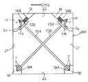
図16は繰り返し荷重を受ける前のX字型筋かいの側面図、図17はX字配置の筋かいに塑性伸びを起させるような少なくとも1/2サイクルの繰り返し荷重を受けた後のX字型筋かい側面図である。
【0038】
図1〜図18において、
更に15A,15Bは筋かい、17,18はブラケット、17A,18Aは筋かい取付部、就中17 A は本発明要素である端部プレートであり、19はコイルバネ受け、21は鉛直枠、22は水平枠、25は耐力壁である。
【0039】
通常は図16のように筋かいは1対の鉛直枠21と水平枠22とに囲まれた耐力壁25内でX字型に配置されており、鉛直枠21,水平枠22で囲まれた1ブロックが耐力壁25をなしている。耐力壁25に剪断力S1,S2が働くと夫々筋かい15A,15Bの順に引張り力が働き、降伏すると塑性伸びが生じて地震エネルギが吸収される。
【0040】
その他方の筋かい15B,15Aには夫々遊隙G3,G3が生じるので、実施例1の場合と同様に挿入型楔10A,10Aが前記遊隙G3,G3に挿入し、遊隙G3,G3は充填されてから、耐力壁25にかかる剪断力による歪みは地震サイクル後にはスリップがなくなり、荷重−変形履歴曲線は図18のように紡錘型となる。
【0041】
【発明の効果】
本発明を実施する事により、前記目的のすべてが達成される。すなわち低周波震動が付与される時、先の震動によって生じる遊隙の悪影響を後の震動時に及ばなくする事が出来る。
【0042】
また建築物の鉄骨固定脚柱のモーメントに対するエネルギ吸収能を増し、筋かいの場合も層間変形角を小さくして遊隙なく直ちに筋かい部材の変形抵抗を発揮出来るようになった。
【0043】
更に荷重−変形履歴曲線が、露出型柱脚では従来のスリップ型でなくボウタイ型(原点立上がり型)となり、筋かいでも同様に従来のスリップ型でなく、紡錘型となり、エネルギ吸収が有効に行われるようになるので、コンピュータによる変形予測もしくは強度計算がし易くなるという効果をもたらす。
【0044】
また本発明の挿入型楔でなる遊隙自動充填機構は構造簡単、廉価であり乍ら、作動が確実であり、上記の効果を容易に得る事が出来る。
【0045】
更に詳しくは、筋かいに本発明を用いると、次のような利点を有する筋かいを得ることが可能となる。
(1)筋かいに圧縮力が作用しない。そのために、座屈防止のための設計が不要である。
(2)筋かい引張力が作用しはじめとすぐに引張抵抗を始めるためスリップ型の復元力特性にはならない。そのため、筋かいとしてのエネルギ吸収能力が最大限に発揮できる。
(3)引張力だけに抵抗するため、筋かいとしての復元力特性は最も簡単な完全弾塑性体モデルとなる。断面積と降伏応力度のみで筋かいを予測できる。更に、端部接合部を保有耐力設計しておれば、筋かいの材長と限界ひずみ度から限界層間変形角も簡単に算出できる。
(4)地震後に筋かいがどの程度塑性伸びを起したか簡単に測定できると共に、その後の余寿命(伸び能力)についても検討可能である。
(5)既存の筋かいについても、端部接合部のわずかな改良により本発明装置は取り付け可能なので、耐震改修の際に、改良型復元力特性を有する筋かいに取り替えることが容易にできる。
【図面の簡単な説明】
【図1】震動開始前の柱脚部側面図。
【図2】震動1/2サイクル後の柱脚部側面図。
【図3】震動1サイクル後の柱脚部側面図。
【図4】図1のA−A矢視図。
【図5】図2のB−B矢視図。
【図6】図3のC−C矢視図。
【図7】挿入型楔の斜視図。
【図8】軸力Nと反時計廻りのモーメントMを受けた時の柱脚部側面図。
【図9】次に軸力Nと時計廻りのモーメントM'を受けた時の柱脚部側面図。
【図10】次に復元して左右アンカーボルトネジ部ナットとベースプレート間に塑性伸びによって遊隙G2,G2が生じた状況を示す柱脚部側面図。
【図11】一方向クラッチを用いた実施例1の側面図。
【図12】従来例(遊隙充填なし)(軸力Nが作用しない場合)の荷重−変形履歴グラフ。
【図13】実施例1(軸力Nが作用しない場合)の荷重−変形履歴グラフ。
【図14】従来例(遊隙充填なし)(軸力Nが作用する場合)の荷重−変形履歴グラフ。
【図15】実施例1(軸力Nが作用する場合)の荷重−変形履歴グラフ。
【図16】震動開始前の実施例2の側面図。
【図17】震動1サイクル後の実施例2側面図。
【図18】実施例2の荷重−変形履歴グラフ。
【符号の説明】
1 実施例1
200 実施例2
2 柱脚部
4 ベースプレート
6 アンカーボルト
6A アンカーボルトネジ部
7 ナット
10 挿入型楔
10A 挿入前の挿入型楔
10B 挿入後の挿入型楔
10K ボルト長孔
10P 傾斜壁
10S 傾斜面
11 楔受け
13 バネ受け
G1,G2,G3 遊隙
N 軸力
M モーメント
C 圧縮反力
V 引張反力
W 隅肉溶接部
14A 圧縮されたコイルバネ
14B 伸びたコイルバネ
20 コンクリート基礎
30 一方向ベアリング
31 ニードルローラ
32,33 ベアリングレース
32A 傾斜溝
34 可動リテーナ
35 押引きコイルバネ
15A,15B 筋かい
17,18 ブラケット
17A,18A 筋かい取付部
19 コイルバネ受け
21 鉛直枠
22 水平枠
25 耐力壁[0001]
[Industrial application fields]
More specifically, the present invention relates to a metal structure such as an exposed column base structure and a brace that has excellent seismic strength and has a function of absorbing seismic energy by plastic deformation. The present invention relates to a filled tension type vibration control structure.
[0002]
[Prior art and issues]
Conventionally, concrete foundation steel column base structures or braces, such as exposed column bases, are the main points for earthquake damage countermeasures and have been found to be the most concentrated place for fracture energy.
[0003]
And because of the tensile plastic deformation of the anchor bolts or brace members that are the tensile stress members generated here, play (play) occurs, and in the case of rapid repeated vibrations, play is always generated before the next tensile stress is applied. However, there is a problem that the required strength as a structure does not appear and energy absorption in the required plastic region cannot be sufficiently performed.
[0004]
Conventional exposed column bases yield anchor bolts against earthquakes and absorb earthquake energy only by plastic elongation of the anchor bolts. In this case, the restoring force characteristic (load-deformation history curve) of the exposed type column base is a slip type, but if a large amount of seismic energy is absorbed by the column base, a large interlayer deformation angle is inevitably generated in the first layer. It will be a thing.
[0005]
As a result of actual examples and experimental observations, it has been clarified that slip on the load-deformation history curve is caused by a gap generated between the base plate and the nut due to plastic elongation of the anchor bolt. These measures include the following.
[0006]
As a conventional example, there has been one in which an elastic spring is inserted between the base plate and the anchor bolt nut in order to reduce the rotational rigidity of the column base, as in the invention described in JP-A-10-299081. Further, as disclosed in Japanese Patent Application Laid-Open No. 2002-4422, a column base is supported by a square sheath-like sheath tube, but this is a low-yield member that is four energy absorbing members by separating a base plate fixed by an anchor bolt. These are means that allow the column base to freely rotate through the point steel piece. These are so-called pin column bases or semi-fixed column bases. It is clear that this does not result in effective sticking.
[0007]
That is, in the prior art, the seismic energy cannot be effectively absorbed by the plastic deformation of the anchor bolt.
[0008]
On the other hand, the conventional anchor bolts often break at the threaded part, but since the strength of the threaded part is high in the recent anchor bolts with rolled thread, the plastic elongation of the shaft part, for example, the elongation rate, does not occur. It can be expected to about 10%. In addition, it has been found that the bending deformation of the base plate is reduced, that is, it is more effective to absorb the seismic energy by increasing the deformation resistance and making it rigid compared to the elongation deformation resistance of the anchor bolt. I came.
[0009]
In the case of a brace, there is a so-called unbonded brace as disclosed in Japanese Patent Application Laid-Open No. 11-36444. This has the merit that it can resist both tensile and compressive stresses, but the brace material has a large cross section. Due to the increase in complexity and size, it is difficult to form an X-shaped brace structure, and there is a problem that it is necessary to provide a K-shaped or V-shaped brace. In addition, unbonded braces were not a countermeasure against the play.
[0010]
Therefore, as a result of earnest experiment research, the present inventor has reached the present invention that eliminates the slip phenomenon by eliminating this gap, makes the interlayer deformation angle smaller than before, and can absorb larger seismic energy.
[0011]
Initially, the effect was confirmed by retightening anchor bolts and brace nuts during the experiment as a means for filling the gap, but it is necessary to automate this when applying to actual buildings, and further experiments As a result of the research, the present invention called a play-filling type damping structure having an automatic filling mechanism as in the present invention has been completed.
[0012]
In other words, as a result of diligent experiments and researches, the present inventor has devised and introduced an automatic space filling mechanism to effectively utilize only the tensile resistance force, and the seismic energy can be obtained only by tensile deformation in the plastic region of the anchor bolt or brace. I was able to absorb it. Also, in the conventional example, without using an unbonded brace that is necessary for countermeasures against buckling due to compressive stress, buckling does not occur on the compression side, and it is possible to obtain a brace that can sufficiently withstand tensile stress continuously. became.
[0013]
OBJECT OF THE INVENTION
The first object of the present invention is to eliminate the adverse effect of the play caused by the previous vibration when the low frequency vibration is applied, during the subsequent vibration.
[0014]
The second object of the present invention is to increase the energy absorption capability especially for the moment of the steel fixed pedestal of the building, and also in the case of a brace, the interlayer deformation angle is reduced so that the deformation resistance can be exerted immediately without any play. It is a thing.
[0015]
The third object of the present invention is that the load-deformation history curve is a non-slip type (starting origin type) instead of the conventional slip type in the exposed type column base, and a spindle type instead of the conventional slip type in the brace as well. In other words, energy absorption can be effectively performed, and deformation prediction or strength calculation by a computer can be easily performed.
[0016]
[Structure of the invention]
According to the present invention,
When a joint is repeatedly subjected to tensile stress due to vibration such as an earthquake, the tensile stress damping structure that absorbs the seismic energy by plastic deformation of a tensile stress member made of anchor bolts or braces, the joint that occurred earlier It is equipped with an automatic filling mechanism in which the clearance between the parts is automatically filled by an insertion type wedge inserted by an elastic biasing force in a direction substantially perpendicular to the tensile stress. A gap-filled tension-type damping structure characterized in that plastic deformation of the tensile stress member is started without a gap (claim 1),
Clearance joint filling tension type vibration control structure is a base plate and the anchor bolt and nut between the junctions or X-shaped brace end plate and struts nut between the junction of the exposed type column base in civil engineering structure according The free-filling tension type damping structure according to Item 1 (Claim 2),
The free-filling tension type damping structure (claim 3) according to
Elastic body for the insertion wedge insert is a coil spring, helical spring, leaf spring, tensile clearance filling according to any one of the preceding
The joint of the free-filling tension type damping structure is a joint between the base plate of the exposed column base and the anchor bolt and nut in the civil engineering structure, and is a non-slip type in which the load-deformation history curve always rises at the origin. The clearance-filled tension type damping structure according to any one of 1 to 4 (Claim 5)
and
The joint of the free-filling tension type damping structure is the joint between the X-shaped brace end plate and the brace nut in the civil engineering building structure, and the load-deformation history curve of the pair of brace is the spindle type The play-filling tension type vibration control structure according to any one of
Is provided.
[0017]
Hereinafter, the present invention will be described in detail using examples.
[0018]
【Example】
1 is a side view of the column base before the start of vibration, FIG. 2 is a side view of the column base after 1/2 cycle of vibration, FIG. 3 is a side view of the column base after one cycle of vibration, and FIG. FIG. 5 is a view taken along the line BB in FIG. 2, FIG. 6 is a view taken along the line CC in FIG. 3, FIG. 7 is a perspective view of the insertion wedge, and FIG. 9 is a side view of the column base when it receives a clockwise moment M, FIG. 9 is a side view of the column base when it receives an axial force N and a clockwise moment M ′, and FIG. FIG. 11 is a side view of a column base portion showing a situation where play gaps G 2 and G 2 are generated by plastic elongation between the left and right anchor bolt screw nuts and the base plate, FIG. 11 is a side view of the first embodiment using a one-way clutch, and FIG. Load-deformation history graph of a conventional example (no clearance filling) (when axial force N does not act), FIG. 13 is a load-deformation history graph of Example 1 (when axial force N does not act) Rough, FIG. 14 is a load-deformation history graph of a conventional example (no clearance filling) (when axial force N is applied), and FIG. 15 is a load-deformation history graph of Example 1 (when axial force N is applied). 16 is a side view of the second embodiment before the start of vibration, FIG. 17 is a side view of the second embodiment after one cycle of vibration, and FIG. 18 is a load-deformation history graph of the second embodiment.
[0019]
1-18,
1 is Example 1, 200 is Example 2, 2 is a column base, 4 is a base plate, 6 is an anchor bolt, 6A is an anchor bolt screw part, 7 is a nut, 10, 10A, and 10B are insertion-type wedges, respectively, before
<Example 1>
First, in the column base, when a vibration is given for 1/2 cycle,
That is, when an axial force N in the column base direction and a moment M in the counterclockwise direction are applied to the column base, the column base is in a state as shown in FIG. 8, and tilts to the left with the left end of the base plate as a fulcrum. If the rigidity of the
[0020]
As the material of the anchor bolt, JISG3138 rolled steel bar for building structure, SNR400A, SNR400B, SNR490B, etc. are most commonly used. A material that has a relatively small work hardening coefficient and is easy to plastically stretch is desirable. In view of economic efficiency, Zn-Al alloy or the like can be used as the superplastic material in addition to the mild steel material.
[0021]
An insertion wedge whose perspective view is shown in FIG. 7 will be described. The material is preferably made of tough cast steel.
[0022]
Next, as shown in FIG. 9, when the reverse moment M ′ acts in the opposite direction (clockwise) of the moment M, the left anchor bolt is pulled and extended with the right end portion of the
[0023]
However, since the gaps G 1 and G 2 are generated in the conventional example as shown in FIG. 9, the load-deformation history curves are as shown in FIG. 12 or FIG. Therefore, the vibration control effect is poor.
[0024]
In the conventional example, the case of FIG. 14 is the case where the axial force N acts, and the case of FIG. 12 is the case where the axial force N does not act.
[0025]
However since the insertion wedge present invention Example 1 closes the clearance and inserted into clearance G 2, G 2 ... 13, the load as in Figure 15 - deformation hysteresis curve origin rising bowtie (bow-tie ) And no slip occurs, so that the seismic energy is easily absorbed and the seismic control effect is increased.
[0026]
Note that the tip inclination angle (vertical angle) θ of the insertion-type wedge of the present invention is 15 ° ≦ θ ≦ 75 °, and more preferably 30 ° ≦ θ ≦ 60 °.
[0027]
The reason for the limitation will be described below.
[0028]
First, if θ does not reach 15 °, the distance in the vertical direction cannot be obtained for the horizontal movement distance of the insertion-type wedge, so that it is not practical, and the thickness of the wedge receiver becomes too small and the rigidity becomes small. If the angle exceeds 75 °, the vertical movement distance becomes too large compared to the horizontal movement distance of the insertion type wedge, and the slope friction force after the insertion type wedge is inserted becomes smaller. This is because the anchor bolt head exposed on the base plate is long and is unstable because it is unstable mechanically.
[0029]
More preferably, 30 ° ≦ θ ≦ 60 °, but the reason for this limitation is as follows.
[0030]
If θ is less than 30 °, the insertion wedge is thin as a whole, although it is within the scope of the present invention, the rigidity tends to be difficult to maintain, and it is difficult to implement the present invention with a limited base plate surface area. Further, if θ exceeds 60 °, the insertion wedge height is slightly increased even within the range of the present invention, and the anchor bolt head length is long as described above, so that it is difficult to maintain stability. . Also in the manufacturing process of the insertion type wedge, when 30 ° ≦ θ ≦ 60 °, there is an advantage that it is easy to handle.
[0031]
In addition, a helical spring, a leaf | plate spring, or a rubber cushion can also be used for the elastic body which pushes an insertion type wedge instead of a coil spring. Two or more of these may be combined. In the present invention, there is no need for a frictional force caused by a pressing force in the radial direction or the thickness direction of the specimen between the specimen surface used in the conventional specimen holder (chuck) of the tensile testing machine and the tapered wedge that squeezes in the tensile direction. Yes, for example, in the present invention, the friction surfaces of the insertion type wedge, the base plate and the wedge receiver that move in a direction substantially perpendicular to the tensile direction have a friction coefficient over a long period of time (for example, 50 years). Thus, it is desirable to perform a surface finish that is small in the wedge insertion direction and kept high in the backward direction, for example, a surface treatment such as sand blasting or galvanizing.
[0032]
The insertion type wedge is for filling the gaps G 1 , G 2 ... Generated in the plastic elongation of the anchor bolt, and is not forcibly press-fitted between the base plate and the wedge receiver. The urging force is sufficient to allow the insertion type wedge to be automatically inserted immediately without any gaps in the play caused by the earthquake. This also applies to the bracing
[0033]
It is desirable to add a one-way clutch 30 that can move only in the insertion direction or a surface treatment having a similar tendency to some or all of these friction surfaces (see FIG. 11). That is, it is desirable that the friction coefficient of the friction surface between the insertion-type wedge and the base plate or the wedge receiver is at least μ in <μ out, where μ in is the friction coefficient in the wedge insertion direction and μ out in the retraction direction.
[0034]
FIG. 11 shows a cross-sectional view of an example in which a one-way clutch including a needle roller, an inclined grooved bearing race, and a movable retainer is used between the lower surface of the insertion wedge and the upper surface of the base plate.
[0035]
The
[0036]
<Example 2>
Example 2 is an example in which the present invention is applied to tensile deformation of a brace.
[0037]
FIG. 16 is a side view of the X-shaped brace before being subjected to repeated loading, and FIG. 17 is an X-shaped after being subjected to at least 1/2 cycle of repeated loading that causes plastic stretching to occur in the X-shaped bracing. FIG.
[0038]
1 to 18,
Furthermore 15A, 15B are bracing, 17, 18 bracket, 17A, 18A are braced attachment portion, especially 17 A is an end plate which is elements of the invention, 19 receives the coil spring, 21 a vertical frame, 22 Is a horizontal frame, and 25 is a bearing wall.
[0039]
Normally, as shown in FIG. 16, the brace is arranged in an X shape within a bearing
[0040]
Its other bracing 15B, since the respective clearance G 3, G 3 occurring in 15A, as in the
[0041]
【The invention's effect】
By implementing the present invention, all of the above objects can be achieved. In other words, when a low frequency vibration is applied, the adverse effect of the play caused by the previous vibration can be minimized during the subsequent vibration.
[0042]
In addition, the energy absorption capacity for the moment of the steel fixed pedestal of the building has been increased, and even in the case of braces, the deformation angle of the brace members can be immediately exerted without play by reducing the interlayer deformation angle.
[0043]
Furthermore, the load-deformation history curve is not a conventional slip type for exposed column bases, but a bow tie type (starting origin type), and a brace is also not a conventional slip type but a spindle type for effective energy absorption. As a result, it is possible to easily perform deformation prediction or strength calculation by a computer.
[0044]
In addition, the automatic gap filling mechanism including the insertion type wedge according to the present invention is simple in structure and inexpensive, but can be reliably operated, and the above-described effects can be easily obtained.
[0045]
More specifically, when the present invention is used for a brace, it is possible to obtain a brace having the following advantages.
(1) The compressive force does not act on the brace. Therefore, the design for buckling prevention is unnecessary.
(2) Since the tensile resistance starts as soon as the brace tensile force begins to act, the slip-type restoring force characteristics are not obtained. Therefore, the energy absorption capability as a brace can be maximized.
(3) Since only the tensile force is resisted, the restoring force characteristic as a bracing is the simplest fully elastic-plastic model. The striation can be predicted only by the cross-sectional area and the yield stress level. Furthermore, if the end joint is designed to have a yield strength, the critical interlayer deformation angle can be easily calculated from the strut length and the critical strain.
(4) It is possible to easily measure how much the struts have undergone plastic elongation after the earthquake and to investigate the remaining life (elongation ability) after that.
(5) Since the present invention apparatus can be attached to the existing brace by slightly improving the end joint portion, it can be easily replaced with a brace having improved restoring force characteristics at the time of seismic retrofit.
[Brief description of the drawings]
FIG. 1 is a side view of a column base before starting vibration.
FIG. 2 is a side view of a column base after a half cycle of vibration.
FIG. 3 is a side view of a column base after one cycle of vibration.
4 is an AA arrow view of FIG. 1;
FIG. 5 is a view taken along arrow BB in FIG. 2;
6 is a view taken along the line CC in FIG. 3;
FIG. 7 is a perspective view of an insertion-type wedge.
FIG. 8 is a side view of a column base when it receives an axial force N and a counterclockwise moment M.
FIG. 9 is a side view of the column base when it receives an axial force N and a clockwise moment M ′.
FIG. 10 is a side view of the column base part showing a situation in which clearances G 2 and G 2 are generated by plastic elongation between the right and left anchor bolt screw nuts and the base plate after restoration.
FIG. 11 is a side view of the first embodiment using a one-way clutch.
FIG. 12 is a load-deformation history graph of a conventional example (no clearance filling) (when axial force N does not act).
13 is a load-deformation history graph of Example 1 (when axial force N does not act). FIG.
FIG. 14 is a load-deformation history graph of a conventional example (no clearance filling) (when axial force N is applied).
15 is a load-deformation history graph of Example 1 (when axial force N is applied). FIG.
FIG. 16 is a side view of Example 2 before the start of vibration.
FIG. 17 is a side view of Example 2 after one vibration cycle.
18 is a load-deformation history graph of Example 2. FIG.
[Explanation of symbols]
1 Example 1
200 Example 2
2
Claims (6)
Priority Applications (1)
| Application Number | Priority Date | Filing Date | Title |
|---|---|---|---|
| JP2002128529A JP3936621B2 (en) | 2002-04-30 | 2002-04-30 | Play-filled tension type damping structure |
Applications Claiming Priority (1)
| Application Number | Priority Date | Filing Date | Title |
|---|---|---|---|
| JP2002128529A JP3936621B2 (en) | 2002-04-30 | 2002-04-30 | Play-filled tension type damping structure |
Publications (2)
| Publication Number | Publication Date |
|---|---|
| JP2003322203A JP2003322203A (en) | 2003-11-14 |
| JP3936621B2 true JP3936621B2 (en) | 2007-06-27 |
Family
ID=29542251
Family Applications (1)
| Application Number | Title | Priority Date | Filing Date |
|---|---|---|---|
| JP2002128529A Expired - Lifetime JP3936621B2 (en) | 2002-04-30 | 2002-04-30 | Play-filled tension type damping structure |
Country Status (1)
| Country | Link |
|---|---|
| JP (1) | JP3936621B2 (en) |
Cited By (2)
| Publication number | Priority date | Publication date | Assignee | Title |
|---|---|---|---|---|
| KR101533940B1 (en) * | 2014-12-30 | 2015-07-06 | 성균관대학교산학협력단 | Loading apparatus for stress relaxation tester |
| CN107178029A (en) * | 2016-03-11 | 2017-09-19 | 株洲时代新材料科技股份有限公司 | A kind of shearing resistance ball shaped steel bearing |
Families Citing this family (5)
| Publication number | Priority date | Publication date | Assignee | Title |
|---|---|---|---|---|
| JP5037031B2 (en) * | 2006-04-13 | 2012-09-26 | 新日本製鐵株式会社 | Wall panel fixing structure and building |
| JP2010024628A (en) * | 2008-07-15 | 2010-02-04 | Hirata Kensetsu:Kk | Building joint metal, and method and tool for pulling out press-in member |
| JP5002569B2 (en) * | 2008-10-30 | 2012-08-15 | 三井ホーム株式会社 | Gate-type frame structure of a wooden building |
| CN108035440A (en) * | 2017-10-27 | 2018-05-15 | 西安建筑科技大学 | A kind of assembled Self-resetting Column Joint with Wedge device |
| CN112761271B (en) * | 2021-01-21 | 2023-03-10 | 广州大学 | Bending damper capable of adjusting damping force |
Family Cites Families (9)
| Publication number | Priority date | Publication date | Assignee | Title |
|---|---|---|---|---|
| DE3200815C2 (en) * | 1982-01-11 | 1987-02-12 | Gerb Gesellschaft für Isolierung mbH & Co KG, 1000 Berlin | Method for aligning the waves of a wave train |
| JP2546247Y2 (en) * | 1992-04-07 | 1997-08-27 | 株式会社熊谷組 | Brace equipment |
| JPH09279602A (en) * | 1996-04-11 | 1997-10-28 | Motoomi Ogata | Column base reinforcing device |
| JPH1061743A (en) * | 1996-08-23 | 1998-03-06 | Ntn Corp | Clutch for slide mechanism |
| JP3579211B2 (en) * | 1997-04-21 | 2004-10-20 | 新日本製鐵株式会社 | Steel column base joining method |
| JPH1136444A (en) * | 1997-07-16 | 1999-02-09 | Takenaka Komuten Co Ltd | Unbonded brace |
| JP2001271868A (en) * | 2000-03-24 | 2001-10-05 | Canon Inc | Vibration damping device |
| JP4424638B2 (en) * | 2000-04-25 | 2010-03-03 | 岡部株式会社 | Anchor bolt seismic construction method |
| JP4546619B2 (en) * | 2000-06-22 | 2010-09-15 | 株式会社竹中工務店 | Column base damping structure |
-
2002
- 2002-04-30 JP JP2002128529A patent/JP3936621B2/en not_active Expired - Lifetime
Cited By (3)
| Publication number | Priority date | Publication date | Assignee | Title |
|---|---|---|---|---|
| KR101533940B1 (en) * | 2014-12-30 | 2015-07-06 | 성균관대학교산학협력단 | Loading apparatus for stress relaxation tester |
| CN107178029A (en) * | 2016-03-11 | 2017-09-19 | 株洲时代新材料科技股份有限公司 | A kind of shearing resistance ball shaped steel bearing |
| CN107178029B (en) * | 2016-03-11 | 2019-10-29 | 株洲时代新材料科技股份有限公司 | A kind of shearing resistance ball shaped steel bearing |
Also Published As
| Publication number | Publication date |
|---|---|
| JP2003322203A (en) | 2003-11-14 |
Similar Documents
| Publication | Publication Date | Title |
|---|---|---|
| JP5296350B2 (en) | Damping member | |
| CN102859097B (en) | Vibration damping metal sheet and building construction | |
| JP3936621B2 (en) | Play-filled tension type damping structure | |
| CN107366373A (en) | A kind of steel plate shear force wall with Self-resetting energy dissipation brace | |
| CN113250209B (en) | Toughness composite buffer for slope flexible protection system and design method thereof | |
| CN114396045B (en) | Anti-seismic anchor cable structure and toughness improving method | |
| JP4424638B2 (en) | Anchor bolt seismic construction method | |
| JP4490853B2 (en) | Brace structure using shape memory alloy | |
| JP6948754B2 (en) | Column base joint structure | |
| CN109680879B (en) | Reinforcing steel bar connector capable of improving continuous collapse resistance of RC frame structure | |
| JP7017879B2 (en) | A bridge equipped with a function-separated shock absorber and a function-separated shock absorber | |
| JP4683571B2 (en) | Steel structure exposed column base structure | |
| JP2001336304A (en) | Vibration control device and vibration control structure | |
| JP2007297792A (en) | Locking structure of side block in bridge bearing | |
| CN110777960A (en) | Beam hinge assembly type self-resetting friction connection node structure and method | |
| CN212478276U (en) | Self-resetting square concrete filled steel tube column base node with friction type anchoring device | |
| CN110685484A (en) | Viscoelastic self-resetting support | |
| JPH09302621A (en) | Low noise type base isolation stacked rubber bearing | |
| JP6862057B2 (en) | Building stigma displacement suppression structure | |
| JP3797086B2 (en) | Friction damper for seismic equipment | |
| JPH07102635A (en) | Pillar beam joint metal | |
| JP5411375B1 (en) | Buildings using seismic control columns | |
| CN106400997A (en) | Round-pipe self-centering buckling restrained brace end connecting device | |
| JP5659703B2 (en) | Elastic-plastic brace anti-seismic structure | |
| Wang et al. | Experimental study on seismic performance of steel artificial controllable plastic hinge (ACPH) with energy-absorption box (EAB) |
Legal Events
| Date | Code | Title | Description |
|---|---|---|---|
| A977 | Report on retrieval |
Free format text: JAPANESE INTERMEDIATE CODE: A971007 Effective date: 20050520 |
|
| A131 | Notification of reasons for refusal |
Free format text: JAPANESE INTERMEDIATE CODE: A131 Effective date: 20050601 |
|
| A521 | Written amendment |
Free format text: JAPANESE INTERMEDIATE CODE: A523 Effective date: 20050801 |
|
| A131 | Notification of reasons for refusal |
Free format text: JAPANESE INTERMEDIATE CODE: A131 Effective date: 20060406 |
|
| A521 | Written amendment |
Free format text: JAPANESE INTERMEDIATE CODE: A523 Effective date: 20060602 |
|
| A131 | Notification of reasons for refusal |
Free format text: JAPANESE INTERMEDIATE CODE: A131 Effective date: 20061010 |
|
| A521 | Written amendment |
Free format text: JAPANESE INTERMEDIATE CODE: A523 Effective date: 20061208 |
|
| TRDD | Decision of grant or rejection written | ||
| A01 | Written decision to grant a patent or to grant a registration (utility model) |
Free format text: JAPANESE INTERMEDIATE CODE: A01 Effective date: 20070312 |
|
| A61 | First payment of annual fees (during grant procedure) |
Free format text: JAPANESE INTERMEDIATE CODE: A61 Effective date: 20070323 |
|
| R150 | Certificate of patent or registration of utility model |
Free format text: JAPANESE INTERMEDIATE CODE: R150 |
|
| FPAY | Renewal fee payment (event date is renewal date of database) |
Free format text: PAYMENT UNTIL: 20100330 Year of fee payment: 3 |
|
| FPAY | Renewal fee payment (event date is renewal date of database) |
Free format text: PAYMENT UNTIL: 20130330 Year of fee payment: 6 |
|
| FPAY | Renewal fee payment (event date is renewal date of database) |
Free format text: PAYMENT UNTIL: 20160330 Year of fee payment: 9 |
|
| R250 | Receipt of annual fees |
Free format text: JAPANESE INTERMEDIATE CODE: R250 |
|
| R250 | Receipt of annual fees |
Free format text: JAPANESE INTERMEDIATE CODE: R250 |