JP3928902B2 - Substrate manufacturing line and substrate manufacturing method - Google Patents
Substrate manufacturing line and substrate manufacturing method Download PDFInfo
- Publication number
- JP3928902B2 JP3928902B2 JP03921398A JP3921398A JP3928902B2 JP 3928902 B2 JP3928902 B2 JP 3928902B2 JP 03921398 A JP03921398 A JP 03921398A JP 3921398 A JP3921398 A JP 3921398A JP 3928902 B2 JP3928902 B2 JP 3928902B2
- Authority
- JP
- Japan
- Prior art keywords
- substrate
- chamber
- robot
- processing
- loading
- Prior art date
- Legal status (The legal status is an assumption and is not a legal conclusion. Google has not performed a legal analysis and makes no representation as to the accuracy of the status listed.)
- Expired - Lifetime
Links
Images


Classifications
-
- G—PHYSICS
- G03—PHOTOGRAPHY; CINEMATOGRAPHY; ANALOGOUS TECHNIQUES USING WAVES OTHER THAN OPTICAL WAVES; ELECTROGRAPHY; HOLOGRAPHY
- G03F—PHOTOMECHANICAL PRODUCTION OF TEXTURED OR PATTERNED SURFACES, e.g. FOR PRINTING, FOR PROCESSING OF SEMICONDUCTOR DEVICES; MATERIALS THEREFOR; ORIGINALS THEREFOR; APPARATUS SPECIALLY ADAPTED THEREFOR
- G03F7/00—Photomechanical, e.g. photolithographic, production of textured or patterned surfaces, e.g. printing surfaces; Materials therefor, e.g. comprising photoresists; Apparatus specially adapted therefor
- G03F7/70—Microphotolithographic exposure; Apparatus therefor
- G03F7/70691—Handling of masks or workpieces
- G03F7/70733—Handling masks and workpieces, e.g. exchange of workpiece or mask, transport of workpiece or mask
- G03F7/7075—Handling workpieces outside exposure position, e.g. SMIF box
Description
【0001】
【発明の属する技術分野】
本発明は基板製造ラインおよび基板製造方法に係り、特にプラズマ、液晶ディスプレイ等の矩形平板状の塗布対象物(以下、主に基板Wと言う)や半導体用ウエハーなどを洗浄した後に、レジスト液、スラリー等の各種液状塗布液を均一な薄膜状態で塗布し、乾燥、パターン露光後に、現像する各処理装置を配設した技術に関するものである。
【0002】
【従来の技術】
特開平4−63643号公報になる「基板搬送装置」によれば、所定処理工程がなされた後のウエハーを所定処理装置から取り出し、処理前のウエハーを処理装置に略同じに搬送及び移載するロボット装置が提案されている。この提案によれば、上下方向に2対のアーム(フォーク)を水平方向に独立駆動可能に設け、さらにアーム外形より大きな仕切り板を上下アームの間に配設することで、アーム間における熱伝達を防止することが示されている。この提案からも、ウエハー処理工程において基板に有害となる熱が伝達されることを防止する熱対策がいかに重量であることが分かる。具体的には、ウエハー上に均一な塗膜を形成する上において重要である。
【0003】
一方、本願出願人は特開平07−326651号公報で「多段処理装置」を提案している。これによれば、上記の基板の塗布前洗浄後の乾燥・冷却と、塗布後のソフト乾燥・冷却と、露光及び現像後の乾燥・冷却を行なうベーク炉を提案している。この提案によれば上下方向に各処理室を多段式に配設し、それぞれに開口部を設け、各開口部の前面から水平に基板を移動させる水平移動体を設け、この水平移動体を上下方向に移動することにより基板を上下方向に移動し、所望の処理室に開口部を介して出し入れする。また、各処理装置間で基板の移載を行なうためにはロボット装置を利用することを提案している。
【0004】
【発明が解決しようとする課題】
一方、ガラス基板を含む基板上に所定塗料を塗布し、露光後に現像を行なうように構成された設備においては、基板の搬送及び移載を司るロボット装置が直接ベーク炉装置内の処理室へガラス基板を受け渡す構造となっている。このためベーク炉装置内の乾燥路(ヒーター含む)へロボットのアーム乃至フォークが直接進入する事となり、フォークがヒーター熱の影響を受ける問題がある。
【0005】
また、上記公報の「多段処理装置」では、基板の塗布前洗浄後の乾燥・冷却と、塗布後のソフト乾燥・冷却と、露光及び現像後の乾燥・冷却を行なうベーク炉において、多段式に配設される各処理室の各開口部の前面から水平に基板を移動させる水平移動体を設け、この水平移動体を上下方向に移動することにより基板を上下方向に移動し、所望の処理室に開口部を介して出し入れするので、直にロボット装置のフォークへ熱伝導されることはないが、その後は、各処理装置間で基板の移載を行なうロボット装置で搬送及び移載を行なうので熱対策は十分とは言えない。
【0006】
したがって、本発明は上述した問題点に鑑みてなされたものであり、ガラス基板及びウエハーを含む基板上に所定処理を行なう基板製造ラインにおいて、熱影響が一切発生しない基板搬送及び移載を実現できる基板製造ラインの提供を目的としている。
【0007】
【課題を解決するための手段】
上述した課題を解決し、目的を達成するために本発明によれば、基板の処理面を上にして基板出入部から1枚毎に基板を取り出した後に、クリーンルーム内の走行路を挟んで配設される複数の処理装置を経て所定処理を前記処理面に施し、前記基板出入部に基板を戻すように構成される基板製造ラインであって、前記基板出入部との間で基板の出し入れを行うとともに、前記複数の処理装置間で1枚毎の基板の出し入れおよび搬送を行うように前記走行路を移動する自走式の第1ロボット装置(5)と、前記複数の処理装置間で1枚毎の基板の出し入れおよび搬送を行うように前記走行路を移動する自走式の第2ロボット装置(6)と、を備え、前記複数の処理装置の内で、基板への温度処理、乾燥処理及び下地処理および冷却処理を行う処理装置は、熱処理室と、冷却室と、前記夫々のロボット装置から搬送される基板の出し入れおよび位置決めを行う基板出入室とが上下方向に分離構成されるとともに、前記熱処理室と前記冷却室および前記基板出入室には、開閉式の蓋体(67)を有した第1開口部(66)が前記走行路に直交する側面に夫々設けられ、さらに前記基板出入室には第1ロボット装置および前記第2ロボット装置による基板の出し入れを行うための第2開口部(33)が前記走行路に対して平行に設けられ、前記基板出入室と前記熱処理室と前記冷却室との間で基板を出し入れするように前記第1開口部に沿って昇降する昇降機能を備える基板交換ロボット装置(15)をさらに備え、前記基板交換ロボット装置は、前記冷却室で冷却された基板を前記基板出入室に出し入れすることで熱影響が、前記第2ロボット装置および前記第1ロボット装置に伝達しないようにすることを特徴としている。
【0008】
また、前記所定処理は、基板の洗浄、加熱乾燥、密着増強剤の付与、一定温度化、レジスト液を含む所定塗布流体の塗布、所定塗布流体の塗布後の塗布後乾燥・冷却(ソフト乾燥、ソフト冷却)、露光、現像、現像後の現像後乾燥・冷却(ハード乾燥、ハード冷却)が含まれることを特徴としている。
【0009】
また、基板の処理面を上にして基板出入部から1枚毎に取り出してから搬送し、クリーンルーム内に配設される複数の処理装置を経て所定処理を前記処理面に施し、複数分が配設される基板出入部に戻すように構成される基板製造ラインであって、前記基板出入部から基板の取り出しと搬送を行う自走式の第1ロボット装置と、前記第1ロボット装置の走行路に略直交するように配設されるとともに端部に露光装置を配設した共通走行路を走行して、基板の取り出しと搬送を行う自走式の第2ロボット装置と、前記第2ロボット装置の下流側に位置する第3ロボット装置と、前記第3ロボット装置の下流側に位置する第4ロボット装置と、前記共通走行路を挟んで配設される前記処理装置の内、洗浄後の基板への加熱乾燥、密着増強剤の付与、一定温度化を行うための第1多段式ベーク炉を、上下方向に分離構成される複数の多段式の処理室と、前記第2ロボット装置から搬送される基板の出し入れ及び位置決めを行う基板出入室と、前記処理室に配設される開閉式の開口部を介して、前記基板出入室との間で基板を出し入れする昇降機能を備える第1基板交換ロボット装置とから構成し、前記第1基板交換ロボット装置により前記開口部と前記基板出入室との間で基板を出し入れ及び昇降するときの熱影響が、前記第2ロボット装置に伝達しないようにし、前記共通走行路を挟んで配設される前記処理装置の内、所定塗布流体の塗布後の基板への塗布後乾燥・冷却(ソフト乾燥、ソフト冷却)を行うための第2多段式ベーク炉を、上下方向に分離構成される複数の多段式の処理室と、前記第3ロボット装置から搬送される基板の出し入れ及び位置決めを行なう基板出入室と、前記処理室に配設される開閉式の開口部を介して、前記基板出入室との間で基板を出し入れするために昇降機能を備える第2基板交換ロボット装置とから構成し、前記第2基板交換ロボット装置により前記開口部と前記基板出入室との間で基板を出し入れ及び昇降するときの熱影響が、前記第3ロボット装置に伝達しないようにし、前記露光装置で露光され、現像後の基板へ現像後の現像後乾燥・冷却(ハード乾燥、ハード冷却)を行うための第3多段式ベーク炉を、上下方向に分離構成される複数の多段式の処理室と、前記第4ロボット装置から搬送される基板の出し入れ及び位置決めを行なう基板出入室と、前記処理室に配設される開閉式の開口部を介して、前記基板出入室との間で基板を出し入れするために昇降機能を備える第3基板交換ロボット装置とから構成し、前記第3基板交換ロボット装置により前記開口部と前記基板出入室との間で基板を出し入れ及び昇降するときの熱影響が、前記第4ロボット装置に伝達しないようにすることを特徴としている。
【0010】
また、基板の処理面を上にして基板出入部から取り出してから搬送し、クリーンルーム内に配設される複数の処理装置を経て所定処理を前記処理面に施し、前記基板出入部に戻す各工程からなる基板製造方法であって、前記各工程には、自走式のロボット装置により、前記ロボット装置の走行路を挟んで配設される前記処理装置の内、基板への温度処理、乾燥処理及び下地処理を行うための多段式ベーク炉に配設される基板出入室に対して基板の出し入れを行う工程と、基板の位置決めを行う工程と、前記多段式ベーク炉の上下方向に分離構成される複数の多段式の処理室に配設される開閉式の開口部を介して、前記位置決め後の基板を前記処理室に対して出し入れするために、前記多段式ベーク炉に併設される基板交換ロボット装置により出し入れ及び昇降させる工程とが含まれ、前記基板交換ロボット装置により前記開口部と前記基板出入室との間で基板を出し入れ及び昇降するときの熱影響が、前記ロボット装置に伝達しないように構成することを特徴としている。
【0011】
【発明の実施の形態】
以下に本発明の実施形態について、添付の図面を参照して述べる。先ず、図1は、基板製造ライン1の全体構成を示しており、左手前上から見た外観斜視図である。
【0012】
本図において、基板製造ライン1には、基板の処理面を上にして、複数分が収容されたカセットを着脱するための基板出入部としてのカセット搬入出装置2が装填される。このカセット搬入出装置2は、図示のように基板製造ライン1の左側において縦一列に4機分が配設される。また、基板製造ライン1の右側にはパターン露光装置23が配設されており自走式のロボットにより基板を搬送し、再びカセット搬入出装置2に処理後の基板を戻すように構成される。そして、図示のように中央に配設される共通搬送レール8を挟み、基板の洗浄処理と、レジスト液、スラリー等の各種液状塗布液を均一な薄膜状態で塗布する塗布処理と、乾燥処理と、パターン露光装置23における所望パターンの露光後に、現像を行うための各処理装置を一列(インライン状)に配置するようにして、主に省スペース化及びメンテナンスの容易化を実現している。
【0013】
図2は、図1の動作説明図を兼ねる外観斜視図であって、図中の二点鎖線で図示のクリーンルーム40は、クラス100以上のクリーン度となるように防塵空調される。このために、上記のように共通搬送レール8を挟んで各処理装置を図示のように対称となる位置に配置し、かつパターン露光装置23をカセット搬入出装置2に対向する位置に配置することで、クリーンルーム40内の空間を無駄なく有効利用できるように配慮されている。また、メンテナンス要員などがクリーンルーム40内において後述する制御盤16や多段式べーク炉14、21、28の各処理室他へアクセスするときに、比較的に容易にアクセスできるようにしている。
【0014】
さらに、基板の洗浄後の洗浄後加熱・乾燥と塗布流体塗布前に基板濡れを高めるための密着増強剤の付与のための噴霧と、基板塗布面全体にわたる一定温度化とを行うための第1多段式ベーク炉14と、レジスト液を含む所定塗布流体の塗布後の塗布後乾燥・冷却であってソフト乾燥、ソフト冷却と呼ばれる処理を行うための第2多段式ベーク炉21と、露光装置23と周辺露光装置25とにより露光された後に、現像装置27により現像されて露光パターンが基板上に形成された後の現像後乾燥・冷却であってハード乾燥、ハード冷却と呼ばれる処理を行うための第3多段式ベーク炉28は、図示のように共通走行レール8の片側に全て位置するようにして、これらに接続されるヒータ電源、空調関係の配管、信号線類の接続が複雑にならないようにする一方で、第3多段式ベーク炉28の右隣りに配設されるユーティリティ装置35から電力、空気圧、冷却水などの供給を受けることができるように思慮されている。
【0015】
再度、図1を参照して、上記のカセット搬入出装置2に隣接して、基板の1枚毎の取り出しと処理後の基板を戻すための自走式の第1ロボット装置3が、走行レール4上において矢印Y方向に往復駆動され、所定位置で停止できるように設けられており、カセット搬入出装置2のいずれかに対向する位置に移動後に、カセットから基板を移載するように構成されている。このために、この第1ロボット装置3は、後述するフォークを上下に配置するとともに、各フォークがカセット搬入出装置2のカセット内に高速度で進入及び後退し、かつ矢印Z方向に上下駆動され、かつまた矢印R方向に旋回駆動する機能を備えている。後述の第2ロボット装置5、第3ロボット装置6、第4ロボット装置7、第5ロボット装置9についても、この第1ロボット装置3と同様の機能を備えている。したがって、各ロボット装置の共通化ができるようにして、運転時のメンテナンス性を高めるようにしている。
【0016】
この第1ロボット装置の走行路である走行レール4に略直交するようにして、共通走行路である走行レール8が、図示のように基板製造ライン1の全長に渡るように設けられている。この走行レール8上を第2ロボット装置5と、この第2ロボット装置5の下流側の第3ロボット装置6と、さらに下流側の第4ロボット装置7が所定プログラムにより走行レール8上で矢印X方向に個別に自走するように構成されている。また、各ロボット装置に設けられたフォークが各処理装置の基板位置決め部または基板位置決めテーブルに高速度で進入及び後退し、矢印Z方向にフォークが上下駆動され、かつ矢印R方向に旋回駆動するようにして、走行レール8上において走行する各ロボット装置により各処理装置の間で基板を自在に移載できるように構成されている。換言すれば、共通走行路である走行レール8の長手方向に沿う対称位置に夫々配設される各種処理装置に対する基板の移載動作を、走行レール8上を走行するロボット装置により実現できるようにしている。
【0017】
この走行レール8の右側端部には、図中においてハッチングで示す一対のバッファ部20が配設されている。これらのバッファ部20に隣接し、かつ走行レール8に略直交するように走行レール10が図示のように配設されており、この走行レール10上を第5ロボット装置9が走行する。バッファ部20は通常は使用せず、装置のトラブル発生時において基板の一時的な待避場所として用いられる。以上が基板移載のための構成である。
【0018】
次に、各処理装置の配置構成について図1を参照して述べ、各処理装置の詳細及び機能については図1の(イ)から(ト)矢視図に基づき後述する。
【0019】
先ず、左側の走行レール4に隣接及び対向して、位置決めテーブル19と図中のハッチングで示すバッファ部20と、低圧紫外線洗浄装置11とが上下方向に配設されている。また、共通走行レール8を挟んでこの低圧水銀紫外線洗浄装置11に対向して、2機のスピンスクラバー装置12が配設されている。また、共通走行レール8を挟んで、下流側に配設される一方のスピンスクラバー装置12に対向して、2機のスピンスクラバー装置12のいずれかにより洗浄後の基板の洗浄後加熱・乾燥と塗布流体塗布前に基板濡れを高めるための密着増強剤の付与のための噴霧と、基板塗布面全体にわたる一定温度化とを行う第1多段式ベーク炉14が配設されており、この第1多段式ベーク炉14にはさらに第1基板交換ロボット装置15が併設されている。この第1基板交換ロボット装置15の右隣りにはメンテナス用空間17からアクセス可能にされる制御盤16が配設されている。
【0020】
共通走行レール8を挟んで、第1基板交換ロボット装置15に対向して、塗布ヘッドを基板に対して相対移動しつつ塗布流体を均一に塗布するための塗布装置13が配設されている。また、この塗布装置13の右隣りには基板位置決めテーブル19を備えた減圧乾燥装置18が配設されている。この減圧乾燥装置18の右隣りには、後述する現像後に形成される基板パターンを非接触で光電変換により検査し画像処理により異常個所を自動的に検査する検査装置30が配設される。
【0021】
また、共通走行レール8を挟んで、減圧乾燥装置18と検査装置30に対向して、塗布装置13によりレジスト液を含む所定塗布流体が塗布された後の塗布後乾燥・冷却を上記のようにソフト乾燥、ソフト冷却する第2多段式ベーク炉21が配設されている。さらにこの第2多段式ベーク炉21には第2基板交換ロボット装置22が併設されている。この第2基板交換ロボット装置22の右隣りには、上記のようにハード乾燥、ハード冷却と呼ばれる処理を行う第3多段式ベーク炉28が配設され、さらにこの第3多段式ベーク炉28には第3基板交換ロボット装置29が併設されている。
【0022】
第3基板交換ロボット装置29に隣接して上記のユーティリティ装置35が配設され、さらに位置決めテーブル19とバッファ部20とが図示のように配設されており、メンテナス用空間17からアクセス可能にされる制御盤16が図示のように対向して配設されている。また、共通走行レール8の右端部近くには、制御盤16に囲まれるようにして2機の位置決めテーブル19が共通走行レール8の長手方向に沿うように配設されており、共通走行レール8の右端部に配設される2機のバッファ部20との間で基板位置決めを行うことで第4ロボット装置7により基板の出し入れを行うとともに、バッファ部20において基板を待機させ、走行レール10上を走行する第5ロボット装置9により露光装置23に設けられる出入部24との間で、基板のやり取りができるように構成されている。ここで、第4ロボット装置7の横の位置決めテーブル19は、位置決めの機能を有しているが、図1のA位置とB位置の間で基板を移動する移行機能をさらに備えている。
【0023】
さらに、共通走行レール8を挟んで、第3多段式ベーク炉28と第3基板交換ロボット装置29に対向して、3機のスピン現像装置27が配設されている。また、共通走行レール8を挟んで、ユーティリティ装置35に対向してi線露光装置26が配設されている。そして、このi線露光装置26の右隣りには基板周辺部の露光を行うための周辺露光装置25が配設されている。
【0024】
以上説明の配置構成において、図2に図示のように、走行レール4上を自走する第1ロボット装置3と、共通走行レール8上を自走する第2ロボット装置5の下流側に位置する第3ロボット装置6と、この第3ロボット装置6の下流側に位置する第4ロボット装置7と、走行レール10上を自走する第5ロボット装置9が矢印X,Y、Z,R方向に移動及び旋回して各多段式ベーク炉14、21、28に設けられた基板出入室62(図6参照)に対して開口部(破線図示)33を介して移載する。また、第1基板交換ロボット装置15と第2基板交換ロボット装置22と第3基板交換ロボット装置29に設けられたフォークが矢印X,Z方向に移動して基板出入室62に移載された基板を上下の各処理室61、62、63、64、65、82、85(図7参照)他に搬入後に再び基板出入室62に戻し、この後に、第2ロボット装置5と第3ロボット装置6による移載を行うようにして、移載のときの熱影響がなく、かつ各多段式ベーク炉14、21、28における基板処理による待機時間に影響されない連続運転を可能にしている。
【0025】
次に、図1における(イ)から(ト)矢視図に基づき各処理装置について述べる。図3は図1の(イ)矢視図であり、カセット搬入出装置2の外観斜視図を示したものである。本図において、上記のように4機分が搬送レール4に沿うように配設されるカセット搬入出装置2はラインの基部となるフレーム100上に設けられており、複数枚数の基板Wを多段式に収納した二点鎖線で図示されるカセット31を交換単位として、上流工程から不図示のロボット装置により搬送される。搬送されたカセット31は位置決め装置102により所定位置にセットされ、カセット31に内蔵された状態の基板Wの位置決めを行い、カセットに設けられた基板の種別認識符号を読み取り、光通信ユニットを中継して制御部に送信し、シャッター101を開くことでクリーンルーム内に基板Wを搬送可能な状態にする。搬送が終了するとシャッター101が閉じられ、処理後の基板が搬送されてくるとシャッター101が開き第1ロボット装置3に設けられたフォークがカセット31内に潜入することでカセットに移載する。カセット31が処理済みの基板で満杯になると、次工程に不図示のロボット装置により搬送される。
【0026】
続いて、図4は図1の(ロ)矢視図であり、バッファ部20と位置決めテーブル19を省略して低圧紫外線洗浄装置11の外観を図示した斜視図である。本図において装置11はフレーム100上に設けられたガイドレール103上を矢印方向に移動する容器105を備えており、この容器105の開口部105aから基板Wを挿入することで、ロボット装置自体の昇降動作により基板Wの移載を行うとともに容器105にセットされた基板Wに紫外線を照射することで、有機物を有機化合物化し、前工程においてプラズマCVDやスパッタリング装置により基板上に形成された金属膜が均一に現れる状態にするとともに有機化合物化することで、次のスピンスクラバー装置12における洗浄作用が容易になるようにしている。また、メンテナンスを考慮して容器105は破線図示と実線図示の位置に移動可能となっており、開閉蓋を設けて随時内部へアクセスできるように構成されている。
【0027】
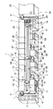
この低圧紫外線洗浄装置11で紫外線が照射されると、図5の図1の(ハ)矢視図であるスピンスクラバー装置12に搬送される。この装置12は、上下する受け渡しユニットに投入された基板Wを図5(a)で示される槽109に開口部106を介して収納するとともに図5(b)に示される回転テーブル110上に吸着保持しモータ108の回転駆動しつつ基板の表面にリンス液を3回路から流出する。これに続き、先端に回転するブラシを設けたアーム107がせり出し、リンス液を流出させながら基板の表面を中心から外側に向けて回動移動しつつブラッシングすることで10ミクロン以上の大きさのゴミを取り除く。このアーム107の移動速度は相対移動速度が中心部と外周部とで一定になるようにコンピュータ制御され、またブラッシング時間は任意に設定できる。これに続き、超音波発振器を先端に設けたアームがせり出し、1メガヘルツ以上の周波数の超音波振動を印加した純水を基板表面上に中心から外周に向けて付与することでサブミクロンの粒子までの洗浄を行う。この時、基板の裏面側にもリンス液を噴射する。これに続き、カップを降下させ、約2000RPMで回転することで、基板表面の洗浄液を振り切りつつ裏面に窒素ガスを噴射し、制圧板によりミストの飛散を防止しつつ基板を乾燥させる。以上のように構成されるスピンスクラバー装置12のほかには、高圧水に空気を混入させ基板に噴射することで洗浄する洗浄装置、スリット状の開口部から高圧空気を基板表面に噴射するエアーナイフ方式の洗浄装置が適宜使用可能である。
【0028】
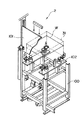
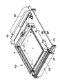
続いて、図6は図1の(ニ)矢視図であり、また、図7は図1の(ホ)矢視図であって、第1多段式ベーク炉14の外観斜視図を夫々示したものであるが、後述する第2、第3多段式ベーク炉22、28と各処理室を除くと略共通する構成であるので、この第1多段式ベーク炉14で代表して述べる。先ず、図6において、製造ラインの基部となるフレーム100上には上述した共通走行レール8が併設される一方で、フィルター装置44がレール間において略連続するように配設されており、クリーンルーム内をダウンフローのエアーが本フロアーより下方のフロアーに排気することによりクリーンに保持するようにしている。また、第1多段式ベーク炉14は、フレーム100上に固定されるとともに、ロボット装置による基板の移載を行う開口部33(破線図示)を設けた基板出入室62を図示の位置に設けている。また、第1多段式ベーク炉14の右側面側には、エアシリンダ装置により開閉される開閉蓋体を設けた開口部66が各室に設けられており、第1基板交換ロボット装置15による基板の出し入れを開口部66を介して行うように構成されている。さらに、共通走行レール8の反対側の側面において第1多段式ベーク炉14には、主にメンテナンスを行うときに開閉される蓋体111が夫々の室に個別に設けられており、蓋体111を図示のように開いた状態から処理室の装置を図示のように外部に引き出せるように構成されている。
【0029】
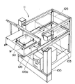
次に、図7において、第1多段式ベーク炉14の有する機能は、洗浄後の基板への温度処理、乾燥処理及び下地処理を行うものである。このために、上段からホットプレート上に設けたルビー球により空隙を設けるようにして基板を加熱するプロキシミティ加熱を行うようにした2機のホットプレート室65と、密着増強剤であるヘキサ・メチル・ジチラザンの噴霧により塗布前の基板の濡れ性を向上させる処理を行う下地処理室64と、空冷により基板を冷却する空冷プレート室63と、第2ロボット装置5と第1基板交換ロボット装置15との間で基板の出し入れ及び位置決めを専用に行う基板出入室62と、液冷により基板全体を均一に冷却することで温度分布をなくして、塗布装置における塗布状態に変動がないようにする液冷プレート室61とを図示のように上下に多段式になるように設けている。このように各室を設けることで占用空間を少なくできるようにしている。
【0030】
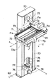
一方、処理室65、64、62、61に配設される開閉式の開口部66を介して、基板出入室62との間で基板Wを出し入れする第1基板交換ロボット装置15は、後述するソフト乾燥・冷却、ハード乾燥・冷却を行う第2基板交換ロボット装置22、第3基板交換ロボット装置29と同様の機能を備えているので、この第1基板交換ロボット装置15で代表して説明すると、フレーム100上にはベース板60が固定されており、このベース板60に右角部位からは起立支柱70が共通走行レール8に隣接するように設けられている。この起立支柱70はベーク炉14と略同じ高さを備えるとともに、昇降基部69を矢印Z方向に駆動することで、この昇降基部69に設けられた上下フォーク71、72を上下方向に移動可能にして、上下フォーク71、72が開口部66を介して各処理室内に潜入することで基板の交換を行えるように構成されている。この昇降基部69にはさらに基板Wの左右縁部の位置決めを行うための横方向矯正装置79が一対分搭載されている。
【0031】
また、共通走行レール8上を自走する第2〜第4ロボット装置5、6、7は略同様に構成されているので、図7に図示の第2ロボット装置5で代表して述べると、ロボット装置5はモータを内蔵する移動基部54と、この基部54に搭載されるとともに上下方向に昇降旋回基部50を昇降させかつスピンスクラバー装置12との間で基板を旋回させる機能を備える昇降基部53と、昇降旋回基部50に搭載されるとともに上下フォーク51、52を処理室に潜入させることで各上下フォーク51、52上に搭載された基板の移載を行う駆動部とから構成されている。
【0032】
図8は、図7の(リ)矢視図であり、第1基板交換ロボット装置15の要部を破断して示した外観斜視図である。本図において、図6、7により既に説明済みの構成部品については同様の符号を附して説明を割愛すると、起立支柱70の上方にはボールネジ74の上端部位を回動自在に支持した落下防止用電磁プレーキ73が固定される一方、このボールネジ74の下端側はベアリングで軸支されており、歯付きプーリ75を固定している。また、モータ77は起立支柱70に固定されておりその回動駆動力を歯付きベルト76を介して歯付きプーリ75に伝達することでボールネジ74を正逆駆動するように構成されている。このボールネジ74には不図示のボールナットが歯合しており、このボールナットを上記の昇降基部69に固定することで、昇降駆動するようにしている。また、万が一の事故発生のときは、電磁ブレーキ73が緊急作動することでボールネジ74の回転を緊急停止することで昇降基部69が自重落下することを防止する。また、ボールネジ74には長手方向に沿うようにカバー80が設けられており、駆動にともない発生するゴミをカバー80で遮蔽するとともに、下方のフィルター装置78により外部にゴミが出ないように配慮している。
【0033】
一方、上下フォーク71、72には特殊樹脂からなる爪体71a、72aが基板の幅寸法にクライアランス分を設けた位置になるように夫々一対分が固定されており、基板を爪体の間で保持して移載を行うようにしている。
【0034】
さらに、図9は、走行レール4、8、10上を自走する第1〜第5ロボット装置の外観斜視図であって、既に説明済みの構成部品については同様の符号を附して説明を割愛すると、図8との比較から分かるように昇降基部69と、昇降旋回基部50は略同じに形成されている。この昇降旋回基部50は、回転軸55を旋回中心として矢印R方向に旋回するとともに、上下方向に駆動される。また、図示のようにロボット装置の上下フォーク51、52にも基板交換ロボット装置に設けたものと略同様の爪体51a、52aが固定されており、移動体56に搭載されるモータ57、58により矢印Y方向に独立駆動したときに爪体51a、52aの間で基板を保持するように構成されている。
【0035】
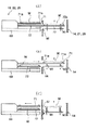
以上説明したように構成されるロボット装置5と基板交換ロボット装置により行われる基板の移載動作について図1のX−X線矢視断面図である図10と、図1のY−Y線矢視断面図である図12の要部断面図であって上下ピンの昇降により移載する場合をそれぞれ説明する。
【0036】
先ず、図10(a)において、スピンスクラバー装置12による洗浄が終了した破線図示の基板Wは、上フォーク51の爪体51aの間において搭載された後に旋回して図示のように開口部33に対向する位置に移動(自走)されて停止する。これに前後して、横方向矯正装置79で基板の横方向の矯正が行なわれる。
【0037】
その後、上フォーク51がベーク炉の開口部33を介して基板出入室62内に潜入して図10(b)に図示のように上下ピン90上に位置して停止する。
下フォーク52も同様に、図3、4で説明したように往復駆動する駆動部を備えている。 共通基部103は、昇降旋回基部50に搭載されるとともに、この共通基部103も駆動部を備えることで、第1、第2移動体と同じ方向に同時に駆動することで和分の速度を得るようにしている。このために基板Wを上述のように載置して保持を行なう上フォーク51を最大ストロークY1で往復駆動するための第1駆動部は、共通基部103に固定されたモータから駆動力を得るボールネジに歯合するボールナットを底面に固定するとともにリニアガイドにより水平移動される第1移動体111を搭載するように構成されている。また、下フォーク52を最大ストロークY2で往復駆動するための第2駆動部は、共通基部103に固定されたモータから駆動力を得るボールネジに歯合するボールナットを底面にブラケットを介して固定するとともにリニアガイドにより水平移動される第2移動体107とから構成されており、下フォーク52を図示のように左右に移動するようにしている。
【0038】
一方、共通基部103は、昇降旋回基部50上に固定されるモータから動力を得るボールネジに歯合するボールナットをブラケットを介して固定するとともに、基部50との間に設けられるリニアガイドにより図示のように最大ストロークY3で左右に移動するように構成されている。
【0039】
以上の構成において、図10(a)に図示のようにロボット装置5が、第1ベーク炉14の基板出入室62の開口部33の位置に移動して、処理済みの基板Wをベーク炉14から取り出し、同時に処理前の基板を上下ピン90上に載置する場合について述べる。ロボット装置5の上フォーク51の爪部51aの間には基板Wが載置されており、上下フォーク51、52は図示のように待機位置に位置している。
【0040】
この状態から、図10(b)に図示のように、共通基部103と第2移動体107が同時に駆動されることで、両者の移動速度を足した最大速度の毎秒2.25mで下フォーク52が移動されて、ベーク炉内において上下ピン90上に載置されている基板Wの下方に移動して停止する。このとき、上フォーク51は駆動されず、図示のように開口部33側に共通基部103の移動分のみ移動されることになる。
【0041】
これに続き、図10(c)に図示のように、ロボット装置5が矢印Z方向に上昇されることにより、上下ピン90上に載置されていた基板Wを下フォーク上に移載する状態にする。このとき、フォーク52の可動範囲は、共通基部103が移動することにより、ロボット装置の寸法に比べて大きく設定できるようになる。
【0042】
これに続き、図11(a)に図示のように、共通基部103が停止したままで、第2移動体107が矢印方向に移動される。これに前後して、第1移動体111が矢印方向に駆動されて上フォーク51に載置されている基板Wを上下ピン90上に移載する準備をする。これに続き、図11(b)に図示のように昇降旋回基部50が矢印Z方向に降下されて、上下ピン90上に基板Wを移載する。この後に、共通基部103と第1移動体111とが同時に駆動されることで、両者の移動速度を足した最大速度の毎秒2.25mで上フォーク51が移動してベーク炉内への移載を終了する。
【0043】
次に、図12は、上下ピン90が不図示のエアシリンダにより上方に駆動されることで上下ピン90上に基板を載置する様子を示した動作説明図である。
【0044】
本図において、先ず図12(a)において、基板交換ロボット装置15、22、29は、ベーク炉14、21、28の基板出入室62に基板が移載されると、昇降基部69が基板出入室62の位置に昇降して、下フォーク72が開口部66を介して潜入して、上下ピン90の下方に潜入して図12(a)の状態にする。
【0045】
これに続き、図12(b)に図示のように上下ピン90が下方に移動されて下フォークに基板を移載する。これと略同時に上フォーク71が潜入することで処理済み基板を基板出入室62内に載置する。この後、図12(c)に図示のように基板交換ロボット装置が所望の処理室まで昇降されて開閉式の開口部66の蓋体67がエアシリンダにより開かれると基板の交換を行う。
【0046】
以上のように基板出入室62において、自走式ロボット装置と昇降のみ行う専用の基板交換ロボット装置による基板移載を個別に行うようにすることで、処理室における処理終了を待つ待機時間をなくすか、最小にできることから処理時間の短縮化(高速化)が実現可能となる。また、多段式ベーク炉にすることで処理時間を要する処理室を上下方向に多数設けるようにできるので、占有面積を最小にできる。また、基板出入室62を設けたことにより、各ロボット装置は、他のロボット装置の動作終了を待って夫々が動作するようにする必要がなくなった。
【0047】
さらに、ベーク炉の処理室においてソフト乾燥、ハード乾燥を行うと基板交換ロボット装置の上下フォーク71、72への熱影響が通常は回避できないが、上記のように基板出入室62において、自走式ロボット装置と昇降のみ行う専用の基板交換ロボット装置による基板移載を個別に行うことで、少なくとも他の処理装置間で基板をやり取りする自走式のほかの第1〜第4ロボット装置への熱伝達は完全に遮断できることになる。
【0048】
次に、図13は以上のように基板の移載を行う動作説明であり、図14は図13のA−A線矢視断面図であって、基板出入室62において基板のセンタリングを行なう様子を示した図である。上記のように起立支柱70はベース60上において共通走行レール8の近傍に配設されている。開口部33から基板出入室62に潜入移載される基板の中心位置CL1と、開口部66から基板出入室62に潜入移載される基板の中心位置CL2との間にズレ分Dが発生する。そこで、基板出入室62内において基板の対角線上にはセンタリングを行なわせるために不図示のエアシンンダにより駆動されるセンタリング装置44が設けられており、共通位置での基板のやり取りができるようにしている。
【0049】
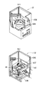
図15は、ベーク炉に内蔵される空冷プレート室63の外観斜視図であり、他の処理室に共通する構成を代表して述べると、上記の開口部66にはエアシリンダ95の作動にともない開閉される開閉蓋体67が夫々設けられており、室内を処理温度または所定雰囲に維持できるようにしている。また、基板Wは基本的には4辺を取り囲む状態で処理が行われることでケーブルガイド99に連通するブロアー98、不図示のヒータによる乾燥ないし下地処理剤の噴霧を行なうように構成されている。
【0050】
図16は上記のように基板の移載を行なうために上下方向に駆動されるピン昇降タイプの場合における上下ピン90の駆動機構を図示している。この駆動機構は、図15の基板Wの下方に位置するように固定されて、貫通孔から上下ピン90が上下するように構成されている。このために、上下ピン90は共通のプレート91上に図示のように多数が植設されており、モータ93の回動駆動にともないリンク92を介してモータ駆動力がプレート91における上下運動に変換されるようにしている。即ち、図17の外観斜視図に図示のように上下ピン90が基板Wの下方から出るようにして基板を載置する。
【0051】
再度、図1において、レジスト液などの所定塗布流体を塗布装置13で塗布された基板は塗布後の基板への温度の低いソフト温度処理及びソフト冷却処理を行うための第2多段式ベーク炉21に移載されるが、このために第2多段式ベーク炉21にはソフトホットプレートを設けたソフトホットプレート室82が上4段にまた、基板出入室62の下方にソフトクールプレートを設けたソフトクールプレート室83が設けられている。
【0052】
一方、下流側の露光装置23で露光された後の基板への温度の高いハード温度処理及びハード冷却を行うための第3多段式ベーク炉28は、第4ロボット装置7から搬送される基板の出し入れ及び位置決めを基板出入室62で行なうとともに、処理室に配設される開閉式の開口部66を介して、第3基板交換ロボット装置29により移載を行なうように構成されており、ハードホットプレートを設けたハードホットプレート室85が上4段にまた、基板出入室62の下方にハードクールプレートを設けたハードクールプレート室86が設けられている。
【0053】
さらに、図18は図1の(ヘ)矢視図であり、塗布装置13の外観斜視図である。この塗布装置13は、フォトレジスト液や絶縁材料、はんだレジストなどの各種塗布流体を塗布するためのものであるが、従来は基板の中央部位にノズルから塗布液を滴下するか、あるいはノズルを中央から外周方向に移動しつつ渦巻き状の軌跡を描いた後に、基板を高速回転させ、回転による遠心力の作用で滴下された塗布液を周囲に拡散することで均一な薄膜を形成するスピンコート法によるものであったが、この方法によれば実際必要量の3倍以上が無駄になることから、塗布対象が矩形形状の基板の場合においては、基板の短辺に該当する幅寸法の全長を有するスリット状の開口部を備える塗布ヘッド120を用いて、開口部から一定量の塗布液を吐出しつつ塗布ヘッド120を上下方向に駆動し、基板側を吸着盤121に吸着保持しモータ123の駆動により塗布ヘッド120に対して相対移動することで均一な薄膜を形成するようにしている。ちなみに、基板移動タイプより、塗布ヘッド移動タイプが主流となりつつある。
【0054】
図19は図1の(ト)矢視図であり、i線露光装置26の一部を破断して図示したものである。この装置26は現像後に残ったレジストによるパターンの全面に対して再度紫外線を照射して、パターンを焼き付けるためのものである。上下ピン90の上下動作により基板Wの移載を行なうように構成されている。
【0055】
また、図20は図1の(チ)矢視図であり、3機分が配設される現像装置27の一部を破断して図示したものである。この装置27は、露光装置23によりレジストの感光されていない部分を現像液により溶かし、レジストによるパターンを形成するためのものであり、上記の上下フォークを有する第4ロボット装置7から基板を受け取り、槽内の吸着盤129により基板を収納保持し、フラットノズル125を設けた移動機構126をレール130上で移動することにより基板の全面に現像液を塗布し、表面を濡らす状態にする。これに続き、フラットノズル125を中央に移動させ、かつ吐出流量を切換え、かつ基板を回転させながら現像を行なう。これと同時に基板の裏面から水洗ノズルユニット127による洗浄を行なう。次に、フラットノズル125を待機位置に移動させ、水洗ノズルを中央に移動させ、基板表面の洗浄を行なうために、回転数を上げ、カップ洗浄を行なった後に、カバー128を降下させてから高速回転によるスピン乾燥を行なう。その後、回転を中止して乾燥ノズルから乾燥空気を送り乾燥し、現像を行なう。
【0056】
図21は、検査装置30の平面図、また図22は図21のX−X線矢視図である。両図において、検査装置30はフレーム100上に固定されるベース140上に設けられるとともに、図示の矢印方向に基板を移動するために不図示のモータから駆動力を得るように構成された移動ステージ143と、ベース140を跨ぐようにして設けられた部材141と、この部材141の下方において基板に対する全面的な照明を行なう照明装置142と、部材141の略中央部位に固定されるミクロパターン検査ヘッド145と、照明装置142からの光であって基板上で反射された画像を反射することで高SN比を有するラインイメージセンサカメラ146に入光させる反射鏡147と、プローブ144とから構成されている。
【0057】
上記の構成において、ロボット装置で移載された基板が移動ステージ143の移動に伴い、移動されつつラインイメージセンサカメラ146により読み取られ、画像処理部(不図示)に画像信号として送られ、所望のパターンとの照合が行われる。その検査結果が異常なしと判断されると、減圧乾燥装置18上の位置決めテーブル19へ移載され、次に第2ロボット装置5により、低圧紫外線洗浄装置11上の位置決めテーブル19へ移載されて、第1ロボット装置3によりカセット搬入出装置2のいずれかのカセット31に戻される。一方、検査装置30により不良品が検出されると、その基板はリワークストッカー(不図示)に移載される。
【0058】
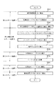
次に、図23、24、25、26は上記のように構成される基板製造ラインの動作説明フローチャートであって、第1〜第5ロボット装置と、第1〜第3基板交換ロボット装置とともに併記した図である。
【0059】
先ず、図1及び図23において、製造ライン1が起動されて準備が整い、最初に行なわれる工程は、カセット搬入出装置2にカセット31が供給されると第1ロボット装置3が走行レール4上を自走で移動し、基板Wを一枚取り出して、ステップS2において洗浄装置11に移載する。その後、洗浄装置11で洗浄後に、ステップS3で位置決めテーブル19上に移載し待機する。
【0060】
次に、ステップS4に進み、共通走行レール8上を走行する第2ロボット装置5が、待機状態の基板を取り出し、第2ロボット装置5の昇降旋回基部50が旋回することで2機分が配設されているスピンスクラバー装置12に基板を対向させてから、いずれかのスピンスクラバー装置12に搬送及び移載して洗浄終了を待つ。起動直後は双方ともスタンバイ状態にあるが、例えば24時間連続運転途中では、洗浄後にスタンバイ状態となっている装置側に基板を移載する。上記のように複数分が配設される装置についても同様であって、このように同じ装置を複数分配設する理由は、処理時間が他の処理装置に比較してより多くかかることによる。洗浄が終了すると、第2ロボット装置5は基板を取り出し、昇降旋回基部50が旋回された後に、第1多段式ベーク炉14の基板出入室62に設けられた開口部33に対向する位置に移動し移載動作を図10で説明したように行なう。
【0061】
次に、ステップS6において、図13に示すように第1多段式ベーク炉14に併設された第1基板交換ロボット装置15により第1多段式ベーク炉14の基板出入室62から基板を取り出し、ホットプレート室65のいずれかに移載し、乾燥後に、ステップS7において、第1基板交換ロボット装置15により下段の空冷プレート室63に移載し、冷却を待ち、ステップS8において、下地処理室64に移載して密着増強剤の噴霧を行なう。続く、ステップS9では、密着増強剤の噴霧された基板の塗布面の温度均一化を図るために最下段の液冷プレート室61に移載して、塗布前に備える。
【0062】
ここで、温度均一化を十分に行なわないと温度の高い部位では例えばレジスト膜形成用の塗料の粘度が低くなることで塗膜が薄くなり、また温度の低い部位では粘度が高くなることで塗膜が厚く形成されることになるので、十分な温度均一化を図る必要がある。このために、液冷プレートの複数の所定部位において温度センサを設け、かつ冷却水路を温度検出によるフィードバック制御するようにしている。以上のように構成される液冷プレート室61において温度均一化が終了すると、第1基板交換ロボット装置15によりステップS10において、基板を再び第1多段式ベーク炉14の基板出入室62に移載する。
【0063】
次に、ステップS11に進み、第2ロボット装置5が基板出入室62に移載された基板を塗布装置13に移載し、塗布ヘッドの相対移動に伴う基板へのレジスト液の均一塗布終了を待つ。この移載のときに、基板出入室62において熱的に完全に分離されるので、各ロボット装置に設けられた上下フォーク間での熱伝導が完全に防止される。
【0064】
続いて、図24のフローチャートのステップS12において、塗布装置13による均一塗布の終了後に第2ロボット装置5が基板を減圧乾燥装置18に移載し、減圧乾燥の終了を待つ。減圧乾燥が終了すると第2ロボット装置5は、位置決めテーブル19に基板を移載して、ステップS14において、、第2ロボット装置5は基板を取り出し、昇降旋回基部50が旋回された後に、第2多段式ベーク炉21の基板出入室62に設けられた開口部33に対向する位置に移動し、移載動作を図10、図11で説明したように行なう。
【0065】
次に、ステップS15において、図13に示すように第2多段式ベーク炉21に併設された第2基板交換ロボット装置22により第2多段式ベーク炉21の基板出入室62から基板を取り出し、上段の4段に設けたソフトホットプレート室82のいずれかに移載し、ソフト乾燥後に、ステップS16において、第2基板交換ロボット装置22により下段のソフトクールプレート室83に移載し、冷却を待ち、ステップS17において基板を再び第2多段式ベーク炉21の基板出入室62に移載する。
【0066】
次に、ステップS18において、共通走行レール8上を自走走行する第3ロボット装置6は、図1においてユーティリティ装置35の右隣りの位置決めテーブル19に基板を搬送、移載する。次に、ステップS19でバッファ部20に基板を移載し、続く処理を待つ状態にする。
【0067】
続く、ステップS20では、共通走行レール8上を自走走行する第4ロボット装置7は、図1において共通走行レール8の最下流に配設された2機の移行装置19に基板を搬送、移載する。次に、ステップS21では、共通走行レール8に直交するように自走する第5ロボット装置9が露光装置23の出入部24に基板を移載して、露光装置23による所定パターンの露光を待つ。
【0068】
続いて、図25のフローチャートのステップS22において、露光が終了すると、第5ロボット装置5が基板を移行装置19に移載する。次に、第4ロボット装置7は基板を周辺露光装置25に移載するために、移行装置19から露光済みの基板を取り出し、昇降旋回基部50が旋回された後に、周辺露光装置25に移載して周辺露光を待つ。ステップS24では、、第4ロボット装置7は周辺露光後の基板をユーティリティ装置35の右隣りの位置決めテーブル19に移載して、隣接するバッファ部20において待機させる。
【0069】
続いて、ステップS25に進み第3ロボット装置6は、3機分が配設されるスピン現像装置27のいずれかに移載し、現像を待ち、現像後にステップS26において、i線露光装置26に移載して紫外線照射を行なう。その後に、ステップS27に進み第3ロボット装置6は、ハード乾燥、冷却を行なうための第3多段式ベーク炉28の開口部33から基板を基板出入室62へ移載する。
【0070】
次に、第3多段式ベーク炉28に併設された第3基板交換ロボット装置29により第3多段式ベーク炉28の基板出入室62から基板を取り出し、上段の4段に設けたハードホットプレート室85のいずれかに移載し、ハード乾燥後に、ステップS29において、第3基板交換ロボット装置29により下段のハードクールプレート室86に移載し、冷却を待ち、ステップS30において基板を再び第3多段式ベーク炉28の基板出入室62に移載する。
【0071】
次に、図26のフローチャートのステップS31において、共通走行レール8上を自走走行する第3ロボット装置6は、検査装置30に基板を搬送、移載する。検査後に良品であると判断されると、第3ロボット装置6はステップS32で、基板を減圧乾燥装置18に位置する位置決めテーブル19に移載する。
【0072】
次に、ステップS33で第2ロボット装置5は、第1ロボット装置3に隣接する位置決めテーブル19に移載する。その後、第1ロボット装置3は、カセット搬入出装置2に基板を移載して終了する。
【0073】
以上の一連の処理により基板上への所定パターンの形成が行なわれる。ここで、各ロボット装置及び各処理装置は待機時間(アイドル時間)をなくすか、極力少なくするように平行分散処理される。
【0074】
図27はこのような平行分散処理の様子を示したタイミングチャートであり、縦軸に上記のロボット装置を示し、横軸に経過時間を示した図である。
【0075】
本図において、各ロボット装置は、上記のステップS1〜34を夫々行なうことで、基板1枚毎の処理を行なう。これらステップS1〜34は、図示のように平行処理されることで、待機時間(アイドル時間)をなくすように集中制御されている。
【0076】
さらに、図28は図26のステップS31において不良品であると判断された後のフローチャートであって、ステップS40において良品であると判断されると上記のようにステップS32に進んでリターンする。また、ステップS40で欠陥が検出されて不良品であると判断されるとステップS41に進み、不図示のリワークストッカーに移載される。その後に、ステップS42においてレジスト膜の剥離が行われて、図23のステップS4に再度進み、再度搬送される。不良品が発生した場合は、ラインを止めメンテナンス要員による装置点検と復旧対策が取られる。レジスト剥離は、本製造ラインとは別のラインで行われる。
【0077】
以上説明したように、基板製造ラインを配設することでクリーンルーム内の占有面積を極力抑えることにより、クリーンルーム設置及びこれの維持のためのコストを大幅に削減でき、かつまた基板を移載するための専用の基板交換ロボット装置をベーク炉に併設することにより、ベーク炉における処理終了後に他の処理工程に基板を移載を行なうロボット装置の到来を待ち時間をなくすようにでき、大幅な処理時間の短縮が実現可能となる基板製造ラインとすることができる。
【0078】
換言すれば従来は、タクトタイムを稼ぐために、搬送ロボットから水平移動体への上下方向の受け渡し位置を多数設定する必要があり、そのためのロボット装置の制御が複雑でコストアップとなる不都合が生じていましたが、その問題も同時に解決される。特に、フォトリソ工程設備内の各処理装置においては、搬送用の第1から第5ロボット装置とのガラス基板の受け渡し高さが極力同じ高さになるように設定されており、ベーク炉のパスエリアである基板出入室もその高さに設定されているため、搬送ロボット自体の昇降動作を極力不要にしてタクトタイムの短縮化が図られるように配慮している。特に、基板出入室と基板交換ロボット装置を設けることによって、搬送ロボット装置の負担が大幅に軽減されて、全体としての高速化が実現可能となった。尚、基板製造ラインは上記の構成に限定されず、特許請求項の範囲に規定される範囲において、種々の構成が可能であることはいうまでもなく、例えば、ソフトベークを行なうまでの工程、露光を行なう工程、ハードベークを行なうまでの工程を別フロアまたは別棟に設けるなどがある。
【0079】
【発明の効果】
以上説明したように、本発明によれば、ガラス基板及びウエハーを含む基板上に所定処理を行なう基板製造ラインにおいて、基板搬送及び移載時において熱影響が一切基板に及ぶことのない基板搬送及び移載を実現できる基板製造ラインおよび基板製造方法を提供できる。
【0080】
【図面の簡単な説明】
【図1】製造ライン1の全体構成を示す外観斜視図である。
【図2】製造ライン1の動作説明図である。
【図3】カセット搬入出装置2の外観斜視図である。
【図4】低圧紫外線洗浄装置11の外観斜視図である。
【図5】スピンスクラバー装置12の要部破断外観斜視図である。
【図6】多段式ベーク炉14の外観斜視図である。
【図7】多段式ベーク炉14と第2ロボット装置5とを示した外観斜視図である。
【図8】第1基板交換ロボット装置を一部破断して示した外観斜視図である。
【図9】ロボット装置の動作説明を示す外観斜視図である。
【図10】ロボット装置で基板の移載を行なう動作説明を示す図1のX−X線矢視断面図である。
【図11】ロボット装置で基板の移載を行なう動作説明を示す図1のX−X線矢視断面図である。
【図12】上下ピンの昇降により基板の移載を行なうために動作説明を示す図1のY−Y線矢視断面図である。
【図13】多段式ベーク炉14と第2ロボット装置5とを示した外観斜視図である。
【図14】図13のA−A線矢視断面図であり、基板出入室62の動作説明を兼ねた図である。
【図15】ベーク炉の処理室の外観斜視図である。
【図16】処理室の上下ピン機構の外観斜視図である。
【図17】上下ピン機構とともに示したベーク炉の処理室の外観斜視図である。
【図18】塗布装置13の外観斜視図である。
【図19】i線露光装置26の外観斜視図である。
【図20】現像装置27の外観斜視図である。
【図21】検査装置30の平面図である。
【図22】図21のX−X線矢視図である。
【図23】製造ライン1の動作説明のための初期段階のフローチャートである。
【図24】製造ライン1の動作説明のための途中段階のフローチャートである。
【図25】製造ライン1の動作説明のための露光後のフローチャートである。
【図26】製造ライン1の動作説明のための終盤のフローチャートである。
【図27】製造ライン1の分散処理説明のためのフローチャートである。
【図28】製造ライン1の検査後のフローチャートである。
【符号の説明】
1 基板製造ライン
2 カセット搬入出装置
3 第1ロボット装置
4 走行レール
5 第2ロボット装置
6 第3ロボット装置
7 第4ロボット装置
8 共通走行レール
9 第5ロボット装置
10 走行レール
11 低圧紫外線洗浄装置
12 スピンスクラバー装置
13 塗布装置
14 第1多段式ベーク炉
15 第1基板交換ロボット装置
16 制御盤
18 減圧乾燥装置
19 位置決めテーブル、移行装置
20 バッファ部
21 第2多段式ベーク炉
22 第2基板交換ロボット装置
23 露光装置
25 周辺露光装置
26 i線露光装置
27 スピン現像装置
28 第3多段式ベーク炉
29 第3基板交換ロボット装置
30 検査装置
31 カセット
33 開口部
40 クリーンルーム
48 モータ
50 昇降旋回基部
51 上フォーク
51a爪体
52 下フォーク
52a爪体
61 液冷プレート室
62 基板出入室
63 空冷プレート室
64 下地処理室
65 ホットプレート室
66 開口部
67 開閉蓋
69 昇降基部
70 起立支柱
71 上フォーク
71a爪体
72 下フォーク
72a爪体
73 電磁ブレーキ
74 ボールネジ
77 モータ
79 横矯正装置
82 ソフトホットプレート室
83 ソフトクールプレート室
85 ハードホットプレート室
86 ハートクールプレート室
90 上下ピン
91 プレート
92 リンク
93 モータ
100 フレーム
120 塗布ヘッド
W 基板[0001]
BACKGROUND OF THE INVENTION
The present invention relates to a substrate production line and a substrate production method, and in particular, after washing a rectangular flat plate-like coating object (hereinafter mainly referred to as a substrate W) such as plasma and a liquid crystal display, a semiconductor wafer, and the like, The present invention relates to a technique in which various processing liquid coating solutions such as slurry are applied in a uniform thin film state, and each processing apparatus for developing after drying and pattern exposure is provided.
[0002]
[Prior art]
According to the “substrate transfer apparatus” disclosed in Japanese Patent Application Laid-Open No. 4-63643, a wafer after a predetermined processing step is taken out from the predetermined processing apparatus, and the wafer before processing is transferred and transferred to the processing apparatus in substantially the same manner. Robotic devices have been proposed. According to this proposal, two pairs of arms (forks) are provided in the vertical direction so that they can be driven independently in the horizontal direction, and a partition plate larger than the outer shape of the arm is arranged between the upper and lower arms, thereby transferring heat between the arms. Has been shown to prevent. Also from this proposal, it can be seen that the heat countermeasure for preventing the transfer of heat which is harmful to the substrate in the wafer processing step is weight. Specifically, it is important in forming a uniform coating film on a wafer.
[0003]
On the other hand, the present applicant has proposed a “multistage processing apparatus” in Japanese Patent Application Laid-Open No. 07-326651. According to this, a baking furnace is proposed which performs drying / cooling after washing before coating of the substrate, soft drying / cooling after coating, and drying / cooling after exposure and development. According to this proposal, the processing chambers are arranged in a multi-stage manner in the vertical direction, each of which is provided with an opening, and a horizontal moving body for moving the substrate horizontally from the front surface of each opening is provided. The substrate is moved in the vertical direction by moving in the direction, and is taken into and out of the desired processing chamber through the opening. In addition, it has been proposed to use a robot apparatus to transfer a substrate between processing apparatuses.
[0004]
[Problems to be solved by the invention]
On the other hand, in a facility configured to apply a predetermined paint on a substrate including a glass substrate and perform development after exposure, the robot apparatus that controls the transfer and transfer of the substrate directly transfers the glass to the processing chamber in the baking furnace apparatus. It is structured to deliver a substrate. For this reason, the robot arm or fork directly enters the drying path (including the heater) in the baking furnace apparatus, and there is a problem that the fork is affected by the heat of the heater.
[0005]
Further, in the “multi-stage processing apparatus” of the above publication, in a baking furnace that performs drying / cooling after cleaning before coating of the substrate, soft drying / cooling after coating, and drying / cooling after exposure and development, in a multi-stage manner. A horizontal moving body for moving the substrate horizontally from the front surface of each opening of each processing chamber provided is provided, and the substrate is moved in the vertical direction by moving the horizontal moving body in the vertical direction, so that the desired processing chamber is obtained. Since the heat transfer is not directly conducted to the fork of the robot apparatus through the opening, the robot apparatus that transfers the substrate between the processing apparatuses is transferred and transferred thereafter. Heat countermeasures are not enough.
[0006]
Therefore, the present invention has been made in view of the above-described problems, and can realize substrate transport and transfer that do not generate any thermal effects in a substrate manufacturing line that performs predetermined processing on a substrate including a glass substrate and a wafer. The purpose is to provide a board production line.
[0007]
[Means for Solving the Problems]
In order to solve the above-described problems and achieve the object, according to the present invention, the processing surface of the substrate is turned up from the substrate entrance / exit. Each board has a substrate take out After In the clean room Across the road A predetermined process is performed on the processing surface through a plurality of processing apparatuses, and the substrate entrance / exit is Board A board production line configured to return, While taking the substrate in and out of the substrate entrance and exit, Among the plurality of processing devices The travel path is moved so as to take in and out the substrates and carry them one by one. Between the self-propelled first robot device (5) and the plurality of processing devices The travel path is moved so as to take in and out the substrates and carry them one by one. A self-propelled second robotic device (6); Of the plurality of processing devices , Temperature treatment, drying treatment and substrate treatment on substrates And a processing apparatus for performing a cooling process is configured such that a heat treatment chamber, a cooling chamber, and a substrate loading / unloading chamber for loading / unloading and positioning of a substrate transferred from each robot apparatus are separated in the vertical direction, and the heat treatment chamber The cooling chamber and the substrate entrance / exit chamber are each provided with a first opening (66) having an openable / closable lid (67) on a side surface orthogonal to the travel path, A second opening (33) for loading and unloading the substrate by the first robot device and the second robot device is provided in parallel to the traveling path, and the substrate loading / unloading chamber, the heat treatment chamber, the cooling chamber, And a substrate exchange robot device (15) having a raising / lowering function for raising and lowering the substrate along the first opening so that the substrate can be taken in and out between them. The substrate exchange robot device is cooled in the cooling chamber. The substrates by out on the substrate loading and unloading chamber The second robot apparatus is affected by heat. and It is characterized by not transmitting to the first robot device.
[0008]
In addition, the predetermined treatment includes substrate cleaning, heat drying, application of an adhesion enhancer, a constant temperature, application of a predetermined application fluid including a resist solution, drying / cooling after application after application of the predetermined application fluid (soft drying, Soft cooling), exposure, development, and post-development drying / cooling (hard drying, hard cooling) after development.
[0009]
Also, each substrate is taken out from the substrate loading / unloading section with the processing surface facing up, and then transported, and a predetermined processing is performed on the processing surface through a plurality of processing devices arranged in a clean room. A substrate production line configured to return to a substrate loading / unloading section provided, a self-propelled first robot device for taking out and transporting a substrate from the substrate loading / unloading portion, and a travel path of the first robot device A self-propelled second robot apparatus that takes out and conveys a substrate by traveling on a common traveling path that is disposed so as to be substantially orthogonal to the substrate and having an exposure device disposed at an end thereof, and the second robot apparatus A cleaned robot among the third robot apparatus positioned downstream of the third robot apparatus, the fourth robot apparatus positioned downstream of the third robot apparatus, and the processing apparatus disposed across the common travel path Heat-drying and adhesion adhesion agent A first multi-stage baking furnace for performing a constant temperature is divided into a plurality of multi-stage processing chambers that are separated in the vertical direction, and a substrate loading / unloading chamber for loading / unloading and positioning of the substrates transferred from the second robot apparatus. And a first substrate exchanging robot device having a lifting / lowering function for moving the substrate in and out of the substrate loading / unloading chamber through an openable / closable opening disposed in the processing chamber. A thermal effect when a substrate is taken in / out and raised / lowered between the opening and the substrate loading / unloading chamber by an exchange robot device is not transmitted to the second robot device, and is disposed across the common travel path. A plurality of multi-stage bake furnaces configured to separate vertically in the second multi-stage baking furnace for performing drying / cooling (soft drying, soft cooling) on the substrate after application of the predetermined application fluid in the processing apparatus. Processing chamber The substrate is taken in and out between the substrate loading / unloading chamber for loading / unloading and positioning of the substrate transferred from the third robot apparatus and the substrate loading / unloading chamber through an openable / closable opening provided in the processing chamber. In order to do so, the second substrate exchange robot device having a lifting function, the thermal effect when the second substrate exchange robot device takes the substrate in and out and raises and lowers between the opening and the substrate entry / exit chamber, A third multi-stage baking furnace for performing post-development drying / cooling (hard drying, hard cooling) after development on the substrate that is exposed by the exposure apparatus and developed after being prevented from being transmitted to the third robot apparatus, A plurality of multi-stage processing chambers separated in the vertical direction, a substrate loading / unloading chamber for loading / unloading and positioning of the substrate transferred from the fourth robot apparatus, and an open / close-type opening provided in the processing chamber. A third substrate exchanging robot device having a lifting / lowering function for moving the substrate in and out of the substrate in / out chamber via the mouth portion, and the third substrate exchanging robot device allows the opening and the substrate exit / exit to be performed. It is characterized in that the thermal effect when the substrate is taken in and out and moved up and down with the entrance is not transmitted to the fourth robot device.
[0010]
In addition, each step of removing the substrate from the substrate loading / unloading portion with the processing surface facing up, carrying the substrate, performing a predetermined treatment on the processing surface via a plurality of processing devices disposed in a clean room, and returning the substrate to the substrate loading / unloading portion A substrate manufacturing method comprising: in each step, a temperature treatment and a drying treatment for a substrate in the processing apparatus disposed across the traveling path of the robot apparatus by a self-propelled robot apparatus. And a substrate loading / unloading chamber disposed in a multi-stage baking furnace for substrate processing, a substrate positioning process, a substrate positioning process, and a vertical direction of the multi-stage baking furnace. In order to take the substrate after positioning into and out of the processing chamber through opening / closing openings provided in a plurality of multi-stage processing chambers, a substrate exchange provided in the multi-stage baking furnace is provided. By robotic device And a step of moving the substrate up and down by the substrate exchange robot apparatus so that a thermal effect when the substrate is inserted and removed between the opening and the substrate loading / unloading chamber is not transmitted to the robot apparatus. It is characterized by doing.
[0011]
DETAILED DESCRIPTION OF THE INVENTION
Embodiments of the present invention will be described below with reference to the accompanying drawings. First, FIG. 1 shows the overall configuration of the
[0012]
In this figure, the
[0013]
FIG. 2 is an external perspective view that also serves as an operation explanatory diagram of FIG. 1, and the
[0014]
In addition, after the cleaning of the substrate, after the cleaning, heating and drying, spraying for applying an adhesion enhancing agent for increasing the substrate wetness before applying the coating fluid, and a first temperature for performing a constant temperature over the entire substrate coating surface. A
[0015]
Referring to FIG. 1 again, a self-propelled
[0016]
A traveling
[0017]
A pair of
[0018]
Next, the arrangement configuration of each processing apparatus will be described with reference to FIG. 1, and details and functions of each processing apparatus will be described later with reference to the arrows (a) to (g) in FIG.
[0019]
First, a positioning table 19, a
[0020]
A
[0021]
Further, after application of a predetermined coating fluid containing a resist solution by the
[0022]
The
[0023]
Further, three
[0024]
In the arrangement described above, as shown in FIG. 2, the
[0025]
Next, each processing apparatus will be described based on the arrow views (a) to (g) in FIG. FIG. 3 is a perspective view of the cassette carrying-in / out
[0026]
Next, FIG. 4 is a (b) arrow view of FIG. 1, and is a perspective view illustrating the appearance of the low-pressure
[0027]
When ultraviolet light is irradiated by the low-pressure
[0028]
Next, FIG. 6 is a view taken in the direction of arrow (d) in FIG. 1, and FIG. 7 is a view taken in the direction of arrow (e) in FIG. 1, and each shows an external perspective view of the first
[0029]
Next, in FIG. 7, the function of the first
[0030]
On the other hand, the substrate entrance /
[0031]
Further, since the second to
[0032]
FIG. 8 is a perspective view of the first substrate exchanging
[0033]
On the other hand, a pair of
[0034]
Further, FIG. 9 is an external perspective view of the first to fifth robot devices that self-travel on the traveling
[0035]
FIG. 10 which is a sectional view taken along the line XX in FIG. 1 and the line YY in FIG. 1 regarding the substrate transfer operation performed by the
[0036]
First, in FIG. 10A, the substrate W shown in the broken line, which has been cleaned by the
[0037]
Thereafter, the
Similarly, the
[0038]
On the other hand, the
[0039]
In the above configuration, the
[0040]
From this state, as shown in FIG. 10B, the
[0041]
Subsequently, as shown in FIG. 10C, the
[0042]
Subsequently, as shown in FIG. 11A, the second moving
[0043]
Next, FIG. 12 is an operation explanatory view showing a state in which the substrate is placed on the upper and
[0044]
In this figure, first, in FIG. 12A, when the substrate is transferred to the substrate loading /
[0045]
Subsequently, as shown in FIG. 12B, the upper and
[0046]
As described above, in the substrate loading /
[0047]
Further, if soft drying and hard drying are performed in the processing chamber of the baking furnace, the thermal effect on the upper and
[0048]
Next, FIG. 13 is an explanation of the operation of transferring the substrate as described above, and FIG. 14 is a cross-sectional view taken along the line AA in FIG. 13 and shows how the substrate is centered in the
[0049]
FIG. 15 is an external perspective view of the air-cooling
[0050]
FIG. 16 shows a driving mechanism for the upper and
[0051]
Referring again to FIG. 1, a second
[0052]
On the other hand, the third
[0053]
18 is a perspective view of the
[0054]
FIG. 19 is a view taken in the direction of arrow (G) in FIG. 1, and shows a part of the i-
[0055]
FIG. 20 is a view taken in the direction of the arrow (H) in FIG. 1, and shows a part of the developing
[0056]
21 is a plan view of the
[0057]
In the above configuration, the substrate transferred by the robot apparatus is read by the line
[0058]
Next, FIGS. 23, 24, 25, and 26 are flowcharts for explaining the operation of the substrate production line configured as described above, and are shown together with the first to fifth robot devices and the first to third substrate replacement robot devices. FIG.
[0059]
First, in FIG. 1 and FIG. 23, when the
[0060]
Next, the process proceeds to step S4, where the
[0061]
Next, in step S6, as shown in FIG. 13, the substrate is taken out from the substrate loading /
[0062]
Here, if the temperature is not sufficiently equalized, for example, the coating film is thinned by decreasing the viscosity of the paint for forming the resist film at a high temperature part, and the viscosity is increased at a low temperature part by increasing the viscosity. Since the film is formed thick, it is necessary to achieve sufficient temperature uniformity. For this purpose, temperature sensors are provided at a plurality of predetermined portions of the liquid cooling plate, and the cooling water channel is feedback-controlled by temperature detection. When the temperature equalization is completed in the liquid
[0063]
Next, in step S11, the
[0064]
Subsequently, in step S12 of the flowchart of FIG. 24, after the uniform coating by the
[0065]
Next, in step S15, the substrate is taken out from the substrate loading /
[0066]
Next, in step S18, the
[0067]
Subsequently, in step S20, the fourth robot device 7 that travels on the
[0068]
Subsequently, in step S22 of the flowchart of FIG. 25, when the exposure is completed, the
[0069]
Subsequently, the process proceeds to step S25, the
[0070]
Next, the substrate is taken out from the substrate loading /
[0071]
Next, in step S <b> 31 of the flowchart of FIG. 26, the
[0072]
Next, in step S <b> 33, the
[0073]
A predetermined pattern is formed on the substrate by the series of processes described above. Here, each robot apparatus and each processing apparatus are subjected to parallel distributed processing so as to eliminate or minimize standby time (idle time).
[0074]
FIG. 27 is a timing chart showing the state of such parallel dispersion processing, in which the above-described robot apparatus is shown on the vertical axis and the elapsed time is shown on the horizontal axis.
[0075]
In this figure, each robot apparatus performs the process for each substrate by performing the above steps S1 to S34. These steps S1 to S34 are centrally controlled so as to eliminate waiting time (idle time) by performing parallel processing as shown in the figure.
[0076]
Further, FIG. 28 is a flowchart after it is determined that the product is defective in step S31 of FIG. 26. When it is determined that the product is non-defective in step S40, the process proceeds to step S32 as described above and returns. Further, when a defect is detected in step S40 and it is determined that the product is defective, the process proceeds to step S41 and is transferred to a rework stocker (not shown). Thereafter, the resist film is peeled off in step S42, and the process proceeds again to step S4 in FIG. When defective products occur, the line is stopped and maintenance personnel check the equipment and take recovery measures. The resist peeling is performed on a line different from the production line.
[0077]
As described above, by arranging the substrate production line to minimize the occupied area in the clean room, the cost for installing and maintaining the clean room can be greatly reduced, and the substrate is transferred again. By installing the dedicated substrate exchange robot device in the bake furnace, it is possible to eliminate the waiting time for the arrival of the robot device that transfers the substrate to another processing process after the processing in the bake furnace is completed, and a significant processing time It can be set as the board | substrate production line which can implement | achieve shortening.
[0078]
In other words, conventionally, in order to earn tact time, it is necessary to set a large number of transfer positions in the vertical direction from the transfer robot to the horizontal moving body, which causes inconvenience that the control of the robot apparatus is complicated and the cost is increased. The problem was solved at the same time. In particular, in each processing apparatus in the photolithographic process equipment, the transfer height of the glass substrate with the first to fifth robot apparatuses for transfer is set to be as high as possible, and the pass area of the baking furnace Since the substrate entry / exit chamber is also set to the height, consideration is given to shortening the tact time by eliminating the lifting / lowering operation of the transfer robot itself as much as possible. In particular, by providing the substrate entrance / exit room and the substrate exchange robot device, the burden on the transfer robot device is greatly reduced, and the overall speed can be increased. The substrate production line is not limited to the above-described configuration, and it goes without saying that various configurations are possible within the scope defined by the claims, for example, a process until soft baking is performed, There are a process for performing exposure and a process for performing hard baking on a separate floor or a separate building.
[0079]
【The invention's effect】
As described above, according to the present invention, in a substrate manufacturing line that performs a predetermined process on a substrate including a glass substrate and a wafer, the substrate transfer and the substrate that are not affected by heat at the time of substrate transfer and transfer, and It is possible to provide a substrate manufacturing line and a substrate manufacturing method capable of realizing transfer.
[0080]
[Brief description of the drawings]
FIG. 1 is an external perspective view showing an overall configuration of a
FIG. 2 is an operation explanatory diagram of the
FIG. 3 is an external perspective view of the cassette carry-in / out
4 is an external perspective view of a low-pressure
FIG. 5 is a perspective view of an external appearance of a main part of the
6 is an external perspective view of a
7 is an external perspective view showing the
FIG. 8 is an external perspective view showing the first substrate replacement robot apparatus with a part broken away.
FIG. 9 is an external perspective view illustrating the operation of the robot apparatus.
10 is a cross-sectional view taken along the line X-X in FIG. 1 illustrating the operation of transferring the substrate with the robot apparatus.
11 is a cross-sectional view taken along the line X-X in FIG. 1 for explaining the operation of transferring a substrate by the robot apparatus.
12 is a cross-sectional view taken along the line YY in FIG. 1 illustrating the operation for transferring the substrate by raising and lowering the upper and lower pins.
13 is an external perspective view showing the
14 is a cross-sectional view taken along the line AA in FIG. 13 and also serves to explain the operation of the substrate entrance /
FIG. 15 is an external perspective view of a processing chamber of a baking furnace.
FIG. 16 is an external perspective view of an upper and lower pin mechanism of a processing chamber.
FIG. 17 is an external perspective view of the processing chamber of the baking furnace shown together with the upper and lower pin mechanisms.
18 is an external perspective view of the
19 is an external perspective view of the i-
20 is an external perspective view of the developing
21 is a plan view of the
22 is a view taken along line XX in FIG. 21. FIG.
23 is a flowchart of an initial stage for explaining the operation of the
FIG. 24 is a flowchart at an intermediate stage for explaining the operation of the
FIG. 25 is a flowchart after exposure for explaining the operation of the
FIG. 26 is a final flowchart for explaining the operation of the
FIG. 27 is a flowchart for explaining distributed processing of the
28 is a flowchart after inspection of the
[Explanation of symbols]
1 Board production line
2 Cassette loading / unloading device
3 First robot device
4 Running rail
5 Second robotic device
6 Third robotic device
7 Fourth robotic device
8 Common running rail
9 Fifth robot device
10 Traveling rail
11 Low pressure UV cleaning equipment
12 Spin scrubber equipment
13 Coating device
14 First multi-stage baking oven
15 First substrate exchange robot
16 Control panel
18 Vacuum drying equipment
19 Positioning table, transition device
20 Buffer part
21 Second multi-stage baking furnace
22 Second substrate exchange robot
23 Exposure equipment
25 Peripheral exposure equipment
26 i-line exposure system
27 Spin development equipment
28 Third multi-stage baking furnace
29 Third substrate exchange robot
30 Inspection equipment
31 cassette
33 opening
40 Clean room
48 motor
50 Lifting swivel base
51 upper fork
51a nail body
52 Lower fork
52a nail body
61 Liquid cooling plate room
62 Board entry / exit room
63 Air cooling plate room
64 Ground treatment room
65 Hot plate room
66 opening
67 Opening and closing lid
69 Lifting base
70 Standing prop
71 upper fork
71a nail body
72 Lower fork
72a nail body
73 Electromagnetic brake
74 Ball screw
77 motor
79 Lateral straightening device
82 Soft hot plate room
83 Soft Cool Plate Room
85 Hard hot plate room
86 Heart Cool Plate Room
90 Top and bottom pins
91 plates
92 links
93 Motor
100 frames
120 coating head
W substrate
Claims (4)
前記基板出入部との間で基板の出し入れを行うとともに、前記複数の処理装置間で1枚毎の基板の出し入れおよび搬送を行うように前記走行路を移動する自走式の第1ロボット装置(5)と、
前記複数の処理装置間で1枚毎の基板の出し入れおよび搬送を行うように前記走行路を移動する自走式の第2ロボット装置(6)と、を備え、
前記複数の処理装置の内で、基板への温度処理、乾燥処理及び下地処理および冷却処理を行う処理装置は、
熱処理室と、冷却室と、前記夫々のロボット装置から搬送される基板の出し入れおよび位置決めを行う基板出入室と、が上下方向に分離構成されるとともに、前記熱処理室と前記冷却室および前記基板出入室には、開閉式の蓋体(67)を有した第1開口部(66)が前記走行路に直交する側面に夫々設けられ、さらに前記基板出入室には第1ロボット装置および前記第2ロボット装置による基板の出し入れを行うための第2開口部(33)が前記走行路に対して平行に設けられ、
前記基板出入室と前記熱処理室と前記冷却室との間で基板を出し入れするように前記第1開口部に沿って昇降する昇降機能を備える基板交換ロボット装置(15)を、さらに備え、
前記基板交換ロボット装置は、前記冷却室で冷却された基板を前記基板出入室に出し入れすることで熱影響が、前記第2ロボット装置および前記第1ロボット装置に伝達しないようにすることを特徴とする基板製造ライン。The processed surface of the substrate in the above after removal of the substrate from the substrate and out unit one by one, performs predetermined processes to the treatment surface through a plurality of processing devices that are disposed across the travel path of the clean room, the A substrate production line configured to return a substrate to a substrate access portion,
Performs out of the substrate between the substrate and out section, the plurality between the processing apparatus and out of the substrate of each sheet in and self-propelled first robotic device for moving the traveling path so as to convey ( 5) and
A self-propelled second robotic device (6) that moves along the traveling path so as to load and unload and transfer each substrate between the plurality of processing apparatuses ,
Among the plurality of processing apparatuses, a processing apparatus that performs temperature processing, drying processing, base processing, and cooling processing on a substrate is provided.
A heat treatment chamber, a cooling chamber, and a substrate loading / unloading chamber for loading / unloading and positioning a substrate transferred from each robot device are separated in the vertical direction, and the heat treatment chamber, the cooling chamber, and the substrate loading / unloading chamber are separated. A first opening (66) having an openable / closable lid (67) is provided in each of the entrances on each side surface orthogonal to the traveling path, and the first robot device and the second entrance are provided in the substrate entrance / exit. A second opening (33) for taking in and out the substrate by the robot apparatus is provided in parallel to the travel path,
A substrate exchanging robot device (15) having a lifting / lowering function that moves up and down along the first opening so as to load / unload the substrate between the substrate loading / unloading chamber, the heat treatment chamber, and the cooling chamber;
The substrate exchange robot apparatus is characterized in that a thermal effect is prevented from being transmitted to the second robot apparatus and the first robot apparatus by moving a substrate cooled in the cooling chamber into and out of the substrate loading / unloading chamber. Substrate production line.
前記空冷式冷却室の下方に配設される前記基板出入室と、
前記基板出入室の下方に配設される液冷式冷却室とを備えることを特徴とする請求項1に記載の基板製造ライン。 In the heat treatment chamber, a plurality of multi-stage baking furnaces are separated in the vertical direction, and the cooling chamber is an air-cooled cooling chamber disposed below the multi-stage baking furnace;
The substrate access chamber disposed below the air-cooled cooling chamber;
The substrate manufacturing line according to claim 1, further comprising a liquid cooling type cooling chamber disposed below the substrate entrance / exit chamber .
基板の横方向のセンタリングを行うために前記第1ロボット装置および前記第2ロボット装置に設けられる1対の第2センタリング手段と、 A pair of second centering means provided in the first robot device and the second robot device for performing lateral centering of the substrate;
基板の縦方向のセンタリングを行うために前記基板交換ロボット装置に設けられる1対の第3センタリング手段と、を備えることを特徴とする請求項1に記載の基板製造ライン。 The substrate manufacturing line according to claim 1, further comprising a pair of third centering means provided in the substrate exchange robot apparatus for performing vertical centering of the substrate.
Priority Applications (1)
| Application Number | Priority Date | Filing Date | Title |
|---|---|---|---|
| JP03921398A JP3928902B2 (en) | 1998-02-20 | 1998-02-20 | Substrate manufacturing line and substrate manufacturing method |
Applications Claiming Priority (1)
| Application Number | Priority Date | Filing Date | Title |
|---|---|---|---|
| JP03921398A JP3928902B2 (en) | 1998-02-20 | 1998-02-20 | Substrate manufacturing line and substrate manufacturing method |
Publications (2)
| Publication Number | Publication Date |
|---|---|
| JPH11238672A JPH11238672A (en) | 1999-08-31 |
| JP3928902B2 true JP3928902B2 (en) | 2007-06-13 |
Family
ID=12546870
Family Applications (1)
| Application Number | Title | Priority Date | Filing Date |
|---|---|---|---|
| JP03921398A Expired - Lifetime JP3928902B2 (en) | 1998-02-20 | 1998-02-20 | Substrate manufacturing line and substrate manufacturing method |
Country Status (1)
| Country | Link |
|---|---|
| JP (1) | JP3928902B2 (en) |
Cited By (2)
| Publication number | Priority date | Publication date | Assignee | Title |
|---|---|---|---|---|
| KR101184668B1 (en) * | 2009-02-16 | 2012-09-21 | 아텔 카부시키카이샤 | Substrate conveying apparatus |
| US9728434B2 (en) | 2010-03-10 | 2017-08-08 | Screen Semiconductor Solutions Co., Ltd. | Substrate processing apparatus, storage device, and method of transporting substrate storing container |
Families Citing this family (14)
| Publication number | Priority date | Publication date | Assignee | Title |
|---|---|---|---|---|
| JP3930244B2 (en) * | 2000-11-10 | 2007-06-13 | 東京エレクトロン株式会社 | Processing equipment |
| JP3943828B2 (en) * | 2000-12-08 | 2007-07-11 | 東京エレクトロン株式会社 | Coating, developing device and pattern forming method |
| TW533460B (en) * | 2001-03-09 | 2003-05-21 | Tokyo Electron Ltd | Processing apparatus |
| JP4114737B2 (en) * | 2001-03-09 | 2008-07-09 | 東京エレクトロン株式会社 | Processing equipment |
| KR100452317B1 (en) * | 2001-07-11 | 2004-10-12 | 삼성전자주식회사 | photo-lithography fabrication system and method there of |
| JP2005142372A (en) * | 2003-11-06 | 2005-06-02 | Tokyo Electron Ltd | Substrate processing apparatus and method |
| US7538857B2 (en) | 2004-12-23 | 2009-05-26 | Asml Netherlands B.V. | Lithographic apparatus and device manufacturing method utilizing a substrate handler |
| US7656506B2 (en) | 2004-12-23 | 2010-02-02 | Asml Netherlands B.V. | Lithographic apparatus and device manufacturing method utilizing a substrate handler |
| JP5189035B2 (en) * | 2004-12-30 | 2013-04-24 | エーエスエムエル ネザーランズ ビー.ブイ. | PCB handler |
| JP4870425B2 (en) * | 2004-12-30 | 2012-02-08 | エーエスエムエル ネザーランズ ビー.ブイ. | PCB handler |
| JP4747618B2 (en) * | 2005-03-16 | 2011-08-17 | パナソニック株式会社 | Panel supply apparatus and panel conveying method |
| JP5637635B2 (en) * | 2012-10-09 | 2014-12-10 | 東亜工業株式会社 | Multistage furnace system |
| KR102619630B1 (en) * | 2020-10-29 | 2024-01-02 | 세메스 주식회사 | Apparatus for treating substrate and method for treating apparatus |
| CN113894027B (en) * | 2021-11-23 | 2024-03-22 | 东莞市鑫华智能制造有限公司 | UV curing equipment |
-
1998
- 1998-02-20 JP JP03921398A patent/JP3928902B2/en not_active Expired - Lifetime
Cited By (2)
| Publication number | Priority date | Publication date | Assignee | Title |
|---|---|---|---|---|
| KR101184668B1 (en) * | 2009-02-16 | 2012-09-21 | 아텔 카부시키카이샤 | Substrate conveying apparatus |
| US9728434B2 (en) | 2010-03-10 | 2017-08-08 | Screen Semiconductor Solutions Co., Ltd. | Substrate processing apparatus, storage device, and method of transporting substrate storing container |
Also Published As
| Publication number | Publication date |
|---|---|
| JPH11238672A (en) | 1999-08-31 |
Similar Documents
| Publication | Publication Date | Title |
|---|---|---|
| JP3928902B2 (en) | Substrate manufacturing line and substrate manufacturing method | |
| TWI401734B (en) | Cleaning apparatus, cleaning method, coating-developing apparatus, coating-developing method, and storage medium | |
| JP4704221B2 (en) | Substrate processing apparatus and substrate processing method | |
| KR101229609B1 (en) | Treating system | |
| KR100493988B1 (en) | Resist processing method and resist processing apparatus | |
| KR100819587B1 (en) | Method of processing substrate, substrate processing system and substrate processing apparatus | |
| JP3213748B2 (en) | Processing system | |
| US6309116B1 (en) | Substrate processing system | |
| JP3484067B2 (en) | Robot device | |
| JP3456919B2 (en) | Substrate processing method and substrate processing apparatus | |
| JP3649048B2 (en) | Resist coating / developing apparatus, and substrate heating processing apparatus and substrate transfer apparatus used therefor | |
| JP3485990B2 (en) | Transfer method and transfer device | |
| JP3983481B2 (en) | Substrate processing apparatus and substrate transfer method in substrate processing apparatus | |
| JP3818858B2 (en) | Liquid processing equipment | |
| JPH08153767A (en) | Substrate treating device | |
| JP3908916B2 (en) | Substrate processing equipment | |
| JP2002329661A (en) | Substrate processing device and method therefor, and method for manufacturing substrate | |
| JP3673397B2 (en) | Substrate cooling device and substrate cooling method | |
| KR102121241B1 (en) | Apparatus for treating substrate | |
| JPH11238776A (en) | Substrate manufacturing line and manufacture of the substrate | |
| JP3605541B2 (en) | Substrate processing equipment | |
| JP3857655B2 (en) | Substrate processing equipment | |
| JPH11238456A (en) | Manufacture of board and manufacturing line | |
| KR102010261B1 (en) | Apparatus and Method for treating a substrate | |
| JP3752136B2 (en) | Development processing apparatus and development processing method |
Legal Events
| Date | Code | Title | Description |
|---|---|---|---|
| A521 | Written amendment |
Free format text: JAPANESE INTERMEDIATE CODE: A523 Effective date: 20050221 |
|
| A621 | Written request for application examination |
Free format text: JAPANESE INTERMEDIATE CODE: A621 Effective date: 20050221 |
|
| RD01 | Notification of change of attorney |
Free format text: JAPANESE INTERMEDIATE CODE: A7426 Effective date: 20050221 |
|
| RD03 | Notification of appointment of power of attorney |
Free format text: JAPANESE INTERMEDIATE CODE: A7423 Effective date: 20050221 |
|
| A977 | Report on retrieval |
Free format text: JAPANESE INTERMEDIATE CODE: A971007 Effective date: 20061115 |
|
| A131 | Notification of reasons for refusal |
Free format text: JAPANESE INTERMEDIATE CODE: A131 Effective date: 20061124 |
|
| A521 | Written amendment |
Free format text: JAPANESE INTERMEDIATE CODE: A523 Effective date: 20070122 |
|
| TRDD | Decision of grant or rejection written | ||
| A01 | Written decision to grant a patent or to grant a registration (utility model) |
Free format text: JAPANESE INTERMEDIATE CODE: A01 Effective date: 20070206 |
|
| A61 | First payment of annual fees (during grant procedure) |
Free format text: JAPANESE INTERMEDIATE CODE: A61 Effective date: 20070302 |
|
| R150 | Certificate of patent or registration of utility model |
Free format text: JAPANESE INTERMEDIATE CODE: R150 |
|
| FPAY | Renewal fee payment (event date is renewal date of database) |
Free format text: PAYMENT UNTIL: 20130316 Year of fee payment: 6 |