JP3911646B2 - Disc brake - Google Patents
Disc brake Download PDFInfo
- Publication number
- JP3911646B2 JP3911646B2 JP32463396A JP32463396A JP3911646B2 JP 3911646 B2 JP3911646 B2 JP 3911646B2 JP 32463396 A JP32463396 A JP 32463396A JP 32463396 A JP32463396 A JP 32463396A JP 3911646 B2 JP3911646 B2 JP 3911646B2
- Authority
- JP
- Japan
- Prior art keywords
- cover spring
- pad
- assembly
- cylinder
- pair
- Prior art date
- Legal status (The legal status is an assumption and is not a legal conclusion. Google has not performed a legal analysis and makes no representation as to the accuracy of the status listed.)
- Expired - Fee Related
Links
Images


Description
【0001】
【発明の属する技術分野】
本発明は、車両の制動に用いられるディスクブレーキに係り、特に二輪自動車に用いて好適なディスクブレーキに関する。
【0002】
【従来の技術】
二輪自動車用のディスクブレーキとしては、ディスクロータを挟んで対向配置した一対のシリンダ部をディスクロータを跨ぐ透過構造のブリッジ部により連接してなるキャリパ本体を車両の非回転部に取付け、該キャリパ本体の一対のシリンダ部間に橋架したピンに一対の摩擦パッドを支持させ、前記キャリパ本体に、前記各摩擦パッドをディスクロータ回転方向に離間する2箇所で押えかつ前記ブリッジ部の透孔を覆うカバースプリングを組付け、前記キャリパ本体の各シリンダ部に内装したピストンの作動により前記一対の摩擦パッドをディスクロータの両面に押付けるようにした、いわゆる対向ピストン型のものがある(例えば、特開平1−188730号公報参照)。
【0003】
【発明が解決しようとする課題】
しかしながら、上記した従来の対向ピストン型ディスクブレーキによれば、パッド押えおよびカバーとして機能するカバースプリングは、前記特開平1−188730号公報にも記載されるように、ディスクロータ回転方向の両側(入口側および出口側)に位置するパッド押え部をそれぞれ一枚板の上に設定しており、このため、摩擦パッドを押える力すなわちパッド押え力が、ディスクロータ軸方向はもとよりディスクロータ回転方向で相互に影響を及ぼし合い、パッド押え力が安定しないという問題があった。
【0004】
本発明は、上記問題点に鑑みてなされたもので、その目的とするところは、パッド押えおよびカバーとして機能するカバースプリングの形状を変更することで、そのパット押え部の相互影響を小さくし、もってパッド押え力の均一安定化を図ることである。
【0005】
【課題を解決するための手段】
上記目的を達成するため、本発明は、上記した対向ピストン型のディスクブレーキにおいて、パッド押えおよびカバーとして機能するカバースプリングを、ディスクロータ回転方向の入口側に摩擦パッドを押えるパッド押え部を有すると共に、該パッド押え部をディスクロータ軸方向に二分割するスリットを有し、該スリットは前記カバースプリングにおける前記ディスクロータ回転方向の両縁部から、前記パッド押え部が前記摩擦パッドに当接する部分を超えた部位まで切り込まれており、かつ、前記カバースプリングの、前記ディスクロータ回転方向の両側縁が前記キャリパ本体に対する組付部となっており、前記キャリパ本体には、一方のシリンダ部の外側から他方のシリンダ部まで前記組付部を差込み可能な組付通路が形成されていることを特徴とする。本発明は、前記組付通路の一方のシリンダ部側の開口には突条が突設されると共に、前記組付通路の他方のシリンダ部側には、該組付通路を閉鎖する縦壁が設けられている構成とすることができる。
【0006】
このようにカバースプリングの両側のパッド押え部にそれぞれディスクロータ軸方向に二分割するスリットを設け、このスリットを摩擦パッドに当接する部分を超えた部位まで切り込むようにすることで、各パッド押え部は、ディスクロータ軸方向で独立にパッド押え力を発生し、これと併せて、ディスクロータ回転方向の入口側および出口側に位置するパッド押え部の相互間での影響も小さくなる。また、両側縁の組付部を利用して、一方のシリンダ部の外側から組付通路にカバースプリングを差込めば、組付けは完了する。
【0007】
【発明の実施の形態】
以下、本発明の実施の形態を添付図面に基いて説明する。
【0008】
図1〜5は、本発明の第1の実施の形態を示したものである。これらの図において、1はキャリパ本体で、ディスクロータDを挟んで対向配置した一対のシリンダ部2、3を、ディスクロータD(図3)を跨ぐブリッジ部4により連接して成っている。ブリッジ部4は、その中央部に四角形状の透孔5を有する透過構造となっており(図1)、その透孔5は、キャリパ本体1に組付けた後述のカバースプリング6により覆われている。なお図1では、理解を容易にするため、カバースプリング6に斜線を付している。
【0009】
本実施の形態において、キャリパ本体1は、上記ブリッジ部4内を分割面として、別途形成された第1のシリンダブロック11と第2のシリンダブロック12とから成っている。第1、第2のシリンダブロック11、12のそれぞれは、ピストン13、14(図3〜5)を収納するボア15、16(図4、5)を設けた本体部11a、12aと、各本体部11a、12aから延ばした各一対の突部11b、12bとを備え、各一対の突部11b、12bを相互に当接させた状態で、一対のボルト17(図2)により締結一体化されている。すなわち、第1、第2のシリンダブロック11、12の本体部11a、12aは、それぞれキャリパ本体1のシリンダ部2、3を構成し、また両者の突部11b、12bは、共働してキャリパ本体1のブリッジ部4を構成するものとなっている。
【0010】
前記ピストン13、14を収納するボア15、16は、第1、第2のシリンダブロック11、12を一体化した状態において同軸上で対向するように配置されている。各ボア15、16には、給液口18(図1、2)から送り込まれたブレーキ液が、各シリンダブロック11、12内に設けた連通孔(図示せず)を通じて供給されるようになっており、このブレーキ液の供給に応じて対向ピストン13、14が、対応するボア15、16から同期して突出するようになる。なお、19,19′は、第1、第2シリンダブロック11、12にそれぞれ設けられたエア抜き用のブリーダである。
【0011】
一方、上記第1、第2のシリンダブロック11、12には、各本体部11a、12aから立上げるようにピンボス20、21(図4、5)が突設されており、この2つのピンボス20と21の間には、一対の摩擦パッド22、23を支持するピン24が橋架されている。各摩擦パッド22、23は、図3に良く示されるように、矩形状の裏板22a,23aとこの裏板に接合したライニング材22b,23bとからなっており、前記ピン24がそれぞれの裏板22a,23aに摺動可能に挿入されている。そして、一対の摩擦パッド22、23は、ディスクロータDを挟むように配置され、2つのピストン13、14が同期して突出することによりディスクロータDの両面に押圧される。第1、第2のシリンダブロック11、12のそれぞれには、各一対のトルク受け25、26が設けられており、各摩擦パッド22、23の裏板22a,23aの側面が各一対のトルク受け25、26に当接することで、所定の制動力が発生するようになっている。なお、前記ピン24はβクリップ27(図5)によりピンボス20、21からの抜けが規制されている。
【0012】
上記ブリッジ部4の透孔5を覆うカバースプリング6は、一対の摩擦パッド22、23の姿勢制御にも用いられるもので、ここでは、第1、第2のシリンダブロック11、12のそれぞれに設けた各一対のボス部28A,28B、29A,29B(図4、5)に2つの隅角部をそれぞれ載せた状態で、キャリパ本体1に組付けられている。
【0013】
カバースプリング6は、図6〜8にも示されるように、前記ピンボス20、21を逃げるように断面U字形とされた本体部30の両側に、前記摩擦パッド22、23に当接するパッド押え部31A,31Bと、前記各ボス部28A,28B、29A,29Bに支承される組付部32A,32Bとを段違いに連設している。そして、カバースプリング6は、その両側の組付部32A,32Bをキャリパ本体1の各ボス部28A,28B、29A,29Bに載せた状態で、その両側のパッド押え部31A,31Bを各摩擦パッド22、23の裏板22a,23aに設けた一対の突起33、34(図4、5)に当接させ、各摩擦パッド22、23をディスクロータDの回転方向の2箇所で弾発的に押えて、その姿勢を制御するように作用する。
【0014】
しかして、カバースプリング6は、前出図6に良く示されるように、そのディスクロータDの軸方向の中間部に、ディスクロータDの回転方向の両側縁から前記パッド押え部31A,31Bを越えた部位まで切り込んだスリット35A,35Bを有している。すなわち、カバースプリング6の、ディスクロータDの回転方向の入口側および出口側の各パッド押え部31A,31B並びに各組付部32A,32Bは、このスリット35A,35BによりディスクロータDの軸方向に二分割されており、カバースプリング6は4つのパッド押え部および組付部を独立に有するものとなっている。これにより、ディスクロータDの軸方向に二分割された各パッド押え部31Aまたは31Bのそれぞれは、ディスクロータ軸方向で相互に影響し合うことがなくなり、これと併せて、ディスクロータDの回転方向の入口側および出口側に位置するパッド押え部31Aおよび31Bも相互間の影響が小さくなる。すなわち、4つのパッド押え部のそれぞれは、他に影響されることなく所定のパッド押え力を発生するようになる。なお、スリット35A,35Bの幅は、摩擦パッド22、23のライニング材22b,23bが全摩耗した場合でも、それらの裏板22a,23aが落ち込まない寸法とされている。
【0015】
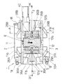
上記のように構成したディスクブレーキでは、キャリパ本体1の各ボア15、16の軸方向に見て、各ボス部28A,28B、29A,29Bと各摩擦パッド22、23の裏板22a,23aとの間には、所定の隙Sが形成されるようになる(図2、3)。この隙Sは、カバースプリング6を組付けるための組付通路として用いられるもので、その組付けに際しては、図3および図9に示すように、一方のシリンダ部2(第1のシリンダブロック11)の外側から、ディスクロータDの軸方向へ矢印Fのようにカバースプリング6を移送し、そのまま前記組付通路Sに差込むようにする。ここで、第1のシリンダブロック11側の一対のボス部28A,28Bには突条36が突設されると共に、第2のシリンダブロック12側の一対のボス部29A,29Bには前記組付通路Sを閉鎖する縦壁37が設けられており(図3)、組付通路Sに差込まれたカバースプリング6は、これら突条36と縦壁37との間に位置決めされた状態で、各ボス部28A,28B、29A,29Bに支承されるようになる。
【0016】
ところで、上記組付通路Sにカバースプリング6を差込むに際しては、カバースプリング6の両側の組付部32A,32Bの先端部を第1のシリンダブロック11側の一対のボス部28A,28Bの突条36に載せて、その断面U字形の本体部30が前記組付通路S内に収まるように(扁平方向へ)弾性変形させ、その変形状態を維持しながら、図9に矢印Fにて示すように、カバースプリング6をキャリパ本体1内に押込むようにする。この場合、カバースプリング6の各パッド押え部31A,31B並びに各組付部32A,32Bが、スリット35A,35BによりディスクロータDの軸方向に二分割されているため、図9に示すように途中まで押込んだ段階で、スリット35A,35Bの、押込方向後側のエッジが前記突条36に干渉する虞れがあり、また、この突条36(ボス部28A,28B)を乗り越えたとしても、摩擦パッド22、23の裏板22a,23aに設けた一対の突起33、34に干渉する虞れがある。
【0017】
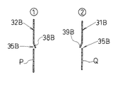
そこで、本第1の実施の形態においては、カバースプリング6のスリット35A,35B内に、カバースプリング6の一部を切り起して成る第1の爪片38A,38Bと第2の爪片39A,39Bとを配置する。この場合、第1の爪片38A,38Bは、組付部32A,32Bに対応する範囲にその幅よりわずか狭い幅で設け、一方第2の爪片39A,39Bは、パッド押え部31A,31Bに対応する範囲にその幅よりわずか狭い幅で設けている。また、第1の爪片38A,38Bおよび第2の爪片39A,39Bは、図8に示すように切起し方向が相互に逆方向とされ、第1の爪片38A,38Bは突条36(ボス部28A,28B)に対する接触面Pと反対方向へ(▲1▼)、第2の爪片39A,39Bは各摩擦パッド22、23に対する接触面Qと反対方向へ(▲2▼)それぞれ折り曲げられている。
【0018】
このような爪片を設けることにより、前記したようにカバースプリング6を組付通路Sに矢印Fのように差込んだ際、先ず第1の爪片38A,38Bが、図10に示すように、ボス部28A,28Bの突条36の上を滑動しながらカバースプリング6を奥側へ案内し、したがってスリット35A,35Bのエッジが該突条36に干渉することはなくなる。また、カバースプリング6がこの突条36を乗り越えてさらに押込まれると、図11に示すように、第2の爪片39A,39Bが摩擦パッド22、23の裏板22a,23aの突起33(34)の下を滑動しながらカバースプリング6を奥側へ案内し、したがってスリット35A,35Bのエッジが該突起33(34)に干渉することはなくなる。なお、第1の爪片38A,38Bの切起こし高さH1 (図10)と第2の爪片39A,39Bの切起こし高さH2 (図11)は、それぞれ突条36、摩擦パッド22、23の突起33,34より食み出す大きさとすることはもちろんである。
【0019】
ここで、キャリパ本体1を構成する第1、第2のシリンダブロック11、12は鋳造により形成され、カバースプリング6を支承する各ボス部28A,28B、29A,29Bは、これら第1、第2のシリンダブロック11、12と一体形成されている。ディスクブレーキの組立に際しては、機械加工により仕上げられた第1、第2のシリンダブロック11、12内のボア15、16にピストン13,14を納めた後、両シリンダブロック11、12を合せてボルト17により一体化し、その後、ピンボス部20、21にピン24を差込みながら、該ピン24に一対の摩擦パッド22、23を吊下支持する。そして、その後、上記したようにカバースプリング6を組付通路S内に差込んで、その4隅を各ボス部28A,28B、29A,29Bに着座させれば、カバースプリング6の組付けは完了する。
【0020】
なお、本実施の形態におけるディスクブレーキは、トルクリンク式として構成されており、キャリパ本体1を構成する第1のシリンダブロック11の一側部には、トルクリンク(図示略)を連結するためのトルクリンクボス部40が一体に設けられている。また、第1のシリンダブロック11には、車両への取付けに用いる2つのねじ孔41(図2)が設けられている。
【0021】
図12は、本発明の第2の実施の形態を示したものである。なお、本第2の実施の形態の全体構造は、上記した第1の実施の形態と実質的に同じであるので、ここでは、同一部分に同一符号を付すこととする。本第2の実施の形態の特徴とするところは、カバースプリング6をキャリパ本体1の外面に4つのボルト43を用いて締付け固定した点にある。すなわち、カバースプリング6は、スリット35A,35BにてディスクロータDの軸方向に二分割された左右の組付部32A,32Bの分割片のそれぞれに通したボルト43を用いてキャリパ本体1の外面に固定されている。この場合も、スリット35A,35Bは、各摩擦パッド22、23の突起33、34に当接する部分を越えた内側まで切込まれており、ディスクロータDの軸方向に分割された各パッド押え部31Aまたは31Bのそれぞれは、上記第1の実施の形態の場合と同様に、ディスクロータ軸方向で相互に影響し合うことなく各摩擦パッド(22,23)に所定の力を加える。しかして、本第2の実施の形態によれば、カバースプリング6の組付けに、複数のねじ孔加工が必要になると共に、複数のボルト43が必要になるので、上記第1の実施の形態に比べて加工コストは増大するが、組付けは簡単となる。
【0022】
【発明の効果】
以上、詳細に説明したように、本発明のディスクブレーキによれば、カバースプリングの複数のパッド押え部の相互影響が、ディスクロータの軸方向はもとよりディスクロータ回転方向で低減するので、均一で安定なパッド押え力を得ることができる。
【図面の簡単な説明】
【図1】本発明の第1の実施の形態としてのディスクブレーキの構造を示す平面図である。
【図2】本ディスクブレーキの構造を示す正面図である。
【図3】図1のA−A矢視線に沿う断面図である。
【図4】図1のW−W矢視線に沿う断面図である。
【図5】図1のT−T矢視線に沿う断面図である。
【図6】本発明で用いるカバースプリングの形状を示す平面図である。
【図7】図6に示したカバースプリングの形状を示す側面図である。
【図8】図6のX−XおよびY−Y矢視線に沿う断面図である。
【図9】キャリパ本体に対するカバースプリング組付けの途中段階を示す平面図である。
【図10】キャリパ本体に対するカバースプリング組付けの途中段階を示す断面図である。
【図11】 キャリパ本体に対するカバースプリング組付けの途中段階を示す断面図である。
【図12】本発明の第2の実施の形態としてのディスクブレーキの構造を示す平面図である。
【符号の説明】
1 キャリパ本体
2、3 シリンダ部
4 ブリッジ部
5 透孔
6 カバースプリング
13、14 ピストン
22、23 摩擦パッド
24 ピン
30 カバースプリングの本体部
31A,31B カバースプリングのパッド押え部
32A,32B カバースプリングの組付部
35A,35B カバースプリングのスリット
D ディスクロータ[0001]
BACKGROUND OF THE INVENTION
The present invention relates to a disc brake used for braking a vehicle, and more particularly to a disc brake suitable for use in a two-wheeled vehicle.
[0002]
[Prior art]
As a disc brake for a two-wheeled vehicle, a caliper main body formed by connecting a pair of cylinder portions opposed to each other with a disc rotor interposed therebetween by a bridge portion having a transmission structure straddling the disc rotor is attached to a non-rotating portion of the vehicle. A cover that supports a pair of friction pads on a pin that is bridged between a pair of cylinder parts, and that holds the friction pads on the caliper body at two locations spaced apart in the disk rotor rotation direction and covers the through holes of the bridge part There is a so-called opposed piston type in which a spring is assembled and the pair of friction pads are pressed against both sides of the disk rotor by the operation of a piston built in each cylinder portion of the caliper body (for example, Japanese Patent Laid-Open No. Hei 1). No. 188730 publication).
[0003]
[Problems to be solved by the invention]
However, according to the conventional opposed piston type disc brake described above, the cover spring functioning as a pad presser and a cover is provided on both sides (inlet) in the disc rotor rotation direction as described in Japanese Patent Laid-Open No. 1-188730. The pad presser portions located on the side and the outlet side are set on a single plate. Therefore, the force to press the friction pad, that is, the pad presser force, is not only in the disc rotor axis direction but also in the disc rotor rotation direction. There was a problem that the pad pressing force was not stable.
[0004]
The present invention has been made in view of the above-mentioned problems, and its object is to reduce the mutual influence of the pad presser by changing the shape of the cover spring that functions as a pad presser and a cover, Thus, the pad pressing force is uniformly stabilized.
[0005]
[Means for Solving the Problems]
In order to achieve the above object, the present invention has a cover spring that functions as a pad presser and a cover in the above-described opposed piston type disc brake, and has a pad presser portion that presses a friction pad on the inlet side in the disc rotor rotation direction. , has a slit which bisects the pad presser portion in the disk rotor axial direction, the slit from both edges of the disc rotor rotation direction of the cover spring, abutting portion the pad presser portion within the friction pad The cover spring is cut into the part beyond which both side edges of the disc rotor in the rotational direction of the disk rotor are assembled to the caliper body, and the caliper body has an outer side of one cylinder part. An assembly passage is formed through which the assembly part can be inserted from the cylinder part to the other cylinder part. It is characterized in. According to the present invention, a protrusion protrudes from the opening on one cylinder portion side of the assembly passage, and a vertical wall that closes the assembly passage is provided on the other cylinder portion side of the assembly passage. It can be set as the structure provided.
[0006]
In this way, each pad retainer is provided with a slit that bisects in the direction of the disc rotor axis in the pad retainers on both sides of the cover spring, and the slit is cut to a portion beyond the portion that contacts the friction pad. Generates a pad presser force independently in the disc rotor axial direction, and at the same time, the influence between the pad presser portions located on the inlet side and the outlet side in the disc rotor rotation direction is reduced. If the cover springs are inserted into the assembly passage from the outside of one of the cylinder parts using the assembly parts on both side edges, the assembly is completed.
[0007]
DETAILED DESCRIPTION OF THE INVENTION
Hereinafter, embodiments of the present invention will be described with reference to the accompanying drawings.
[0008]
1 to 5 show a first embodiment of the present invention. In these drawings,
[0009]
In the present embodiment, the caliper
[0010]
The
[0011]
On the other hand, the first and
[0012]
The
[0013]
As shown in FIGS. 6 to 8, the
[0014]
Thus, the
[0015]
In the disc brake constructed as described above, the
[0016]
By the way, when the
[0017]
Therefore, in the first embodiment, the
[0018]
By providing such a claw piece, when the
[0019]
Here, the first and
[0020]
The disc brake in the present embodiment is configured as a torque link type, and a torque link (not shown) is connected to one side of the
[0021]
FIG. 12 shows a second embodiment of the present invention. The overall structure of the second embodiment is substantially the same as that of the first embodiment described above, and therefore, the same parts are denoted by the same reference numerals here. The feature of the second embodiment is that the
[0022]
【The invention's effect】
As described above in detail, according to the disc brake of the present invention, the mutual influence of the plurality of pad pressing portions of the cover spring is reduced not only in the axial direction of the disc rotor but also in the disc rotor rotating direction, so that it is uniform and stable. Pad pressing force can be obtained.
[Brief description of the drawings]
FIG. 1 is a plan view showing a structure of a disc brake as a first embodiment of the present invention.
FIG. 2 is a front view showing the structure of the disc brake.
3 is a cross-sectional view taken along line AA in FIG.
4 is a cross-sectional view taken along the line WW of FIG.
5 is a cross-sectional view taken along the line TT of FIG.
FIG. 6 is a plan view showing the shape of a cover spring used in the present invention.
7 is a side view showing the shape of the cover spring shown in FIG. 6. FIG.
8 is a cross-sectional view taken along lines XX and YY in FIG.
FIG. 9 is a plan view showing an intermediate stage of assembly of the cover spring to the caliper body.
FIG. 10 is a cross-sectional view showing an intermediate stage of the assembly of the cover spring to the caliper body.
FIG. 11 is a cross-sectional view showing an intermediate stage of assembly of the cover spring to the caliper body .
FIG. 12 is a plan view showing the structure of a disc brake as a second embodiment of the present invention.
[Explanation of symbols]
DESCRIPTION OF
Claims (2)
Priority Applications (1)
| Application Number | Priority Date | Filing Date | Title |
|---|---|---|---|
| JP32463396A JP3911646B2 (en) | 1996-11-20 | 1996-11-20 | Disc brake |
Applications Claiming Priority (1)
| Application Number | Priority Date | Filing Date | Title |
|---|---|---|---|
| JP32463396A JP3911646B2 (en) | 1996-11-20 | 1996-11-20 | Disc brake |
Publications (2)
| Publication Number | Publication Date |
|---|---|
| JPH10153226A JPH10153226A (en) | 1998-06-09 |
| JP3911646B2 true JP3911646B2 (en) | 2007-05-09 |
Family
ID=18168014
Family Applications (1)
| Application Number | Title | Priority Date | Filing Date |
|---|---|---|---|
| JP32463396A Expired - Fee Related JP3911646B2 (en) | 1996-11-20 | 1996-11-20 | Disc brake |
Country Status (1)
| Country | Link |
|---|---|
| JP (1) | JP3911646B2 (en) |
Families Citing this family (2)
| Publication number | Priority date | Publication date | Assignee | Title |
|---|---|---|---|---|
| JP4703864B2 (en) * | 2000-10-20 | 2011-06-15 | 日立オートモティブシステムズ株式会社 | Disc brake |
| US8857575B2 (en) * | 2012-12-11 | 2014-10-14 | Arvinmeritor Technology, Llc | Brake caliper assembly having a pad shield |
-
1996
- 1996-11-20 JP JP32463396A patent/JP3911646B2/en not_active Expired - Fee Related
Also Published As
| Publication number | Publication date |
|---|---|
| JPH10153226A (en) | 1998-06-09 |
Similar Documents
| Publication | Publication Date | Title |
|---|---|---|
| US6378666B1 (en) | Disc brake | |
| US4467897A (en) | Disc brake with first and second springs for preventing the vibration of friction pad | |
| JP3911646B2 (en) | Disc brake | |
| JPS628653B2 (en) | ||
| JPS58211032A (en) | Disc brake | |
| JP4703864B2 (en) | Disc brake | |
| JP4028347B2 (en) | Disc brake | |
| JP4552173B2 (en) | Disc brake | |
| JPH0534346Y2 (en) | ||
| JP3905168B2 (en) | Caliper for disc brake | |
| JPH0719267A (en) | Disc brake for vehicle | |
| JPS628654B2 (en) | ||
| JPH10213167A (en) | Disc brake for vehicle | |
| JP2587547Y2 (en) | Disc brake | |
| JPH059535Y2 (en) | ||
| JPH0611368Y2 (en) | Opposed disc brake | |
| JP2593184Y2 (en) | Pin slide type vehicle disc brake | |
| JPH07139570A (en) | Disc brake device | |
| JPH1061696A (en) | Disc brake for vehicle | |
| JP3873251B2 (en) | Disc brake | |
| JPS6024989Y2 (en) | disc brake | |
| JP2542331Y2 (en) | Assembling structure of friction pad and shim plate for vehicle disk brake | |
| JP2531452Y2 (en) | Pin slide type disc brake wear indicator mounting structure | |
| JPH0550174U (en) | Brake shoe support structure for vehicle drum brakes | |
| JP3806887B2 (en) | Disc brake |
Legal Events
| Date | Code | Title | Description |
|---|---|---|---|
| A521 | Written amendment |
Free format text: JAPANESE INTERMEDIATE CODE: A523 Effective date: 20040225 |
|
| A711 | Notification of change in applicant |
Free format text: JAPANESE INTERMEDIATE CODE: A712 Effective date: 20041125 |
|
| A977 | Report on retrieval |
Free format text: JAPANESE INTERMEDIATE CODE: A971007 Effective date: 20060413 |
|
| A131 | Notification of reasons for refusal |
Free format text: JAPANESE INTERMEDIATE CODE: A131 Effective date: 20060426 |
|
| A521 | Written amendment |
Free format text: JAPANESE INTERMEDIATE CODE: A523 Effective date: 20060621 |
|
| TRDD | Decision of grant or rejection written | ||
| A01 | Written decision to grant a patent or to grant a registration (utility model) |
Free format text: JAPANESE INTERMEDIATE CODE: A01 Effective date: 20070110 |
|
| A61 | First payment of annual fees (during grant procedure) |
Free format text: JAPANESE INTERMEDIATE CODE: A61 Effective date: 20070118 |
|
| R150 | Certificate of patent or registration of utility model |
Free format text: JAPANESE INTERMEDIATE CODE: R150 |
|
| S111 | Request for change of ownership or part of ownership |
Free format text: JAPANESE INTERMEDIATE CODE: R313111 |
|
| FPAY | Renewal fee payment (event date is renewal date of database) |
Free format text: PAYMENT UNTIL: 20100209 Year of fee payment: 3 |
|
| R350 | Written notification of registration of transfer |
Free format text: JAPANESE INTERMEDIATE CODE: R350 |
|
| FPAY | Renewal fee payment (event date is renewal date of database) |
Free format text: PAYMENT UNTIL: 20110209 Year of fee payment: 4 |
|
| FPAY | Renewal fee payment (event date is renewal date of database) |
Free format text: PAYMENT UNTIL: 20110209 Year of fee payment: 4 |
|
| FPAY | Renewal fee payment (event date is renewal date of database) |
Free format text: PAYMENT UNTIL: 20120209 Year of fee payment: 5 |
|
| FPAY | Renewal fee payment (event date is renewal date of database) |
Free format text: PAYMENT UNTIL: 20130209 Year of fee payment: 6 |
|
| LAPS | Cancellation because of no payment of annual fees |