JP3873251B2 - Disc brake - Google Patents
Disc brake Download PDFInfo
- Publication number
- JP3873251B2 JP3873251B2 JP2002081475A JP2002081475A JP3873251B2 JP 3873251 B2 JP3873251 B2 JP 3873251B2 JP 2002081475 A JP2002081475 A JP 2002081475A JP 2002081475 A JP2002081475 A JP 2002081475A JP 3873251 B2 JP3873251 B2 JP 3873251B2
- Authority
- JP
- Japan
- Prior art keywords
- torque receiving
- disk rotor
- brake
- brake pads
- rotor
- Prior art date
- Legal status (The legal status is an assumption and is not a legal conclusion. Google has not performed a legal analysis and makes no representation as to the accuracy of the status listed.)
- Expired - Fee Related
Links
Images


Landscapes
- Braking Arrangements (AREA)
Description
【0001】
【発明の属する技術分野】
本発明は、自動車の制動に用いられるディスクブレーキに係り、特に二輪自動車に用いて好適なディスクブレーキに関する。
【0002】
【従来の技術】
二輪自動車用のディスクブレーキとしては、少なくともディスクロータの片側にその回転方向に配列して複数のピストンを内装したキャリパ本体に、前記各ピストンに対応してディスクロータの両側に配置した複数対のブレーキパッドを摺動可能に支持させ、前記各ピストンの推進に応じて各対のブレーキパッドをディスクロータに圧接させると共に、各ブレーキパッドの側面をキャリパ本体に設けたトルク受け部に支承させて制動力を発生するものがある。なお、前記ピストンは、キャリパ固定型のディスクブレーキではディスクロータの両側に対向して配置され、キャリパ浮動型のディスクブレーキではディスクロータの片側のみに配置されることになる。
【0003】
このようなディスクブレーキにおいて、各ブレーキパッドは、従来一般には、ディスクロータの片側においてディスクロータの回転中心でそれぞれのパッド中心線を交わらせるように配置され、一方、上記キャリパ本体に設けられるトルク受け部のうち、ピストンの相互間に配置されるトルク受け部は、隣接する2つのブレーキパッドに共用される構造となっていた(例えば、実開平3−53643号公報参照)。
【0004】
【発明が解決しようとする課題】
すなわち、上記した従来のディスクブレーキにおいては、各パッド中心線の交点をディスクロータの回転中心に一致させかつピストン間のトルク受け部を隣接するブレーキパッドで共用させる都合上、該ピストン間のトルク受け部は、キャリパの剛性向上のためにキャリパ外周側のディスクロータ接線方向の肉厚をある程度厚くする必要があり、また、ブレーキパッドのディスクロータ当接面積を大きくするためにキャリパ内周側のディスクロータ接線方向の肉厚をある程度薄くする必要があるため、ディスクロータの回転中心を通る線上に左右トルク受け面の対称中心を置いた二等辺三角形の形態をとらざるを得ないものとなっていた。換言すれば、ピストン間のトルク受け部は、その特有の三角形状によりキャリパ外周側がかなり厚肉となり、その分、ピストンの配列ピッチが大きくなって、キャリパが大型化し、重量も重くなってしまう、という問題があった。
【0005】
なお、単にピストンの配列ピッチを小さくすべく、ピストン間のトルク受け部の肉厚を減じた場合は、該トルク受け部の三角形の先端側が欠損してしまい、トルク受け部の長さを十分に確保することができずに、制動時にブレーキパッドの姿勢が不安定になる、という新たな問題を引き起こすことになる。
【0006】
本発明は、上記問題点に鑑みてなされたもので、その課題とするところは、ピストン間のトルク受け部の肉厚を、その長さを犠牲にすることなく可及的に削減し、もってキャリパの小型、軽量化に寄与するディスクブレーキを提供することにある。
【0007】
【課題を解決するための手段】
上記課題を解決するため、本請求項1の発明は、少なくともディスクロータの片側にその回転方向に配列して複数のピストンを内装したキャリパ本体に、ディスクロータの両側に配置した一対のブレーキパッドを前記ピストンと対応させて複数対設け、前記各ピストンの推進により各対のブレーキパッドをディスクロータに圧接させると共に、各ブレーキパッドを摺動可能に支持するトルク受け部に支承させて制動力を発生するディスクブレーキにおいて、前記ディスクロータの片側において互いに隣り合うブレーキパッドの間に位置するトルク受け部の各トルク受け面におけるディスクロータ回転中心側の延長線は、前記ディスクロータの径方向で該ディスクロータの回転中心に対して前記キャリパ本体と同じ側のディスクロータ領域内の一点で交わるとともに、前記ディスクロータの片側において互いに隣り合う前記各ブレーキパッドは、該ブレーキパッドに関する両トルク受け面の間の中心点を通って両ブレーキパッドの間に位置するトルク受け部のトルク受け面に平行なパッド中心線をそれぞれ有しており、前記ディスクロータの径方向で該ディスクロータの回転中心に関して前記キャリパ本体とは反対側の領域の一点でそれぞれのパッド中心線が交わるように配置されることを特徴とする。
【0008】
このように構成したディスクブレーキにおいては、ディスクロータの片側に互いに隣り合って配置されるブレーキパッドの間に位置するトルク受け部の各トルク受け面におけるディスクロータ回転中心側の延長線を、前記ディスクロータの径方向で該ディスクロータの回転中心に対して前記キャリパ本体と同じ側のディスクロータ領域内の一点で交わらせるとともに、該各ブレーキパッドの中心線の交点をディスクロータの回転中心に関して前記キャリパ本体とは反対側の領域に設定したことにより、キャリパ本体に設けられるピストン間のトルク受け部の先端角度が小さくなり、キャリパ本体の剛性を向上させつつ、ブレーキパッドのディスクロータ当接面積を大きくすることができ、また、該トルク受け部のキャリパ外周側の肉厚を薄くしても、トルク受け部の先端側が欠損することはなくなる。
【0009】
本請求項2の発明は、上記請求項1の発明において、前記各ブレーキパッドのパッド中心線の交点は、ディスクロータの領域内にあることを特徴とする。
【0010】
このように構成したディスクブレーキにおいては、各ブレーキパッドのパッド中心線の交点を、ディスクロータの径方向で該ディスクロータの回転中心に関して前記キャリパ本体とは反対側の領域のうちディスクロータの領域内に設定したことにより、キャリパ本体に設けられるピストン間のトルク受け部の肉厚を適正に設定することができる。
【0011】
本請求項3の発明は、上記請求項1または2の発明において、前記各ブレーキパッドのパッド中心線の交点は、前記ディスクロータの片側に配置された各ブレーキパッドの間に位置するトルク受け部の中心線上に位置することを特徴とする。
【0012】
このように構成したディスクブレーキにおいては、前記各ブレーキパッドのパッド中心線の交点が、前記ディスクロータの片側に配置された各ブレーキパッドの間に位置するトルク受け部の中心線上を位置させることにより、各ブレーキパッドを相似形状のものとすることができる。
【0013】
【発明の実施の形態】
以下、本発明の実施の形態を添付図面に基いて説明する。
【0014】
図1〜7は、本発明の第1の実施の形態を示したものである。本第1の実施の形態としてのディスクブレーキはキャリパ固定型として構成されており、その全体的な構造は、図2〜4に示すようになっている。これらの図において、1はキャリパ本体で、キャリパ本体1は、ディスクロータDの内側(車両内側)に配置されるインナ側キャリパ半割体2AとディスクロータDの外側(車両外側)に配置されるアウタ側キャリパ半割体2Bとを突合せて一体に連結してなっている。より詳しくは、各キャリパ半割体2Aおよび2Bは、ディスクロータDの周方向に沿う両側部と中央部との3箇所にディスクロータDの軸方向へ突出する突出部3A、4A、5Aおよび3B、4B、5Bを有しており、これら突出部同士3Aと3B、4Aと4B、5Aと5Bとを相互に突合せた状態で、これら突出部同士を通したタイボルト6により連結されている。
【0015】
キャリパ本体1は、そのアウタ側キャリパ半割体2Bに設けた二つの取付孔7を通したボルト(図示略)により車体の非回転部、例えば自動二輪車のフロントフォークに取付けられるようになっており、この取付状態で、前記突出部同士3Aと3B、4Aと4B、5Aと5BとがディスクロータDを跨ぐ位置に配置され、これによりインナ側キャリパ半割体2Aとアウタ側キャリパ半割体2Bとを連接する3つのブリッジ部8、9、10が形成される。そして、これら3つのブリッジ部8、9、10の相互間は開口部11として構成されており、各開口部11内には、後に詳述するカバースプリング12が配置されている。
【0016】
また、インナ側キャリパ半割体2Aおよびアウタ側キャリパ半割体2Bのそれぞれには、ディスクロータDの回転方向に配列して2つのボア(シリンダ)13、14が形成されており、各ボア13、14には有底筒状のピストン15、16が摺動可能に納められている(図2)。なお、これらボア13、14およびピストン15、16については、インナ側のみを示し、アウタ側については図示を省略している。ボア13、14は、インナ側キャリパ半割体2Aとアウタ側キャリパ半割体2Aとの間で相互に対向するように配置されており、したがってキャリパは、ここではディスクロータDを挟んで二対のピストン15、16を備えた4ピストン対向タイプとなっている。一方、各ボア13、14には、各キャリパ半割体2Aおよび2B内に設けた連通孔17(図2)を通して給液口19からブレーキ液が供給されるようになっており、このブレーキ液の供給に応じて二対のピストン15、16が同期して突出するようになる。なお、18はエア抜き用のブリーダを装着するためのブリーダ取付穴である。
【0017】
また、インナ側キャリパ半割体2Aおよびアウタ側キャリパ半割体2Bのそれぞれには、前記2つの開口部11に臨んでピンボス20および21が突設されている。インナ側キャリパ半割体2A側のピンボス20とアウタ側キャリパ半割体2B側のピンボス21とは、ディスクロータDの軸方向に相対向して配置されており、この相対向する2つのピンボス20と21との間には、ディスクロータDの両側に配置した各一対のブレーキパッド22、23を摺動可能に支持するパッドピン24が橋架されている。なお、各一対のブレーキパッド22、23については、インナ側のみを示し、アウタ側については図示を省略している。各ブレーキパッド22、23は、矩形の裏板25とこの裏板25に接合された摩擦材26とからなっており、その裏板25の上部中央に一体に形成した被吊り部27に設けた孔28(図5参照)を利用して前記パッドピン24に通し掛けされている。裏板26にはまた、その上部の左右縁部に前記カバースプリング12に当接する肩部29、30(図5参照)が形成されているが、これについては後に詳述する。
【0018】
一方、インナ側キャリパ半割体2Aおよびアウタ側キャリパ半割体2Bには、図2に示すように各一対のブレーキパッド22、23をガイドしかつ各一対のブレーキパッド22、23に生じるトルクを受ける3つのガイド部(トルク受け部)31、32、33が設けられている。なお、これらトルク受け部31、32、33については、インナ側のみを示し、アウタ側については図示を省略している。この3つのトルク受け部31、32、33は、前記ブリッジ部8、9、10を形成するインナ側キャリパ半割体2Aの各突出部3A、4A、5Aおよびアウタ側キャリパ半割体2Bの各突出部3B、4B、5Bに連接する部位に設けられている。これらトルク受け部のうち、キャリパ本体1の両側に位置するトルク受け部31、32はそれぞれの内側(図1参照)にトルク受け面31a、32aを有し、中間のトルク受け部33はその両側にトルク受け面33a,33bをそれぞれ有しており、トルク受け面31aと33aとが、また、トルク受け面32aと33bとが平行に形成されている。そして、各一対のブレーキパッド22、23は中間のトルク受け部33を共用して、その両側のトルク受け面33a,33bとこれらと対立するキャリパ両側のトルク受け部31、32のトルク受け面31a、32aとの間でガイドされるようになっている。
【0019】
しかして、本第1の実施の形態のキャリパ本体1においては、図1に示すように、各一対のブレーキパッド22、23は、それぞれの中心線(パッド中心線)C1、C2が、ディスクロータDの片側においてディスクロータの回転中心Oに関してキャリパ本体1が設けられた側とディスクロータDの径方向の反対側における領域の一点Pで交わるように配置されている。そして、本第1の実施の形態においては、交点PはディスクロータDの領域内にあるように設定されている。
【0020】
また、本第1の実施の形態のキャリパ本体1においては、中間(ブレーキパッド22、23間)のトルク受け部33の中心線(ディスクロータDの接線方向における肉厚の中心線)C0上に、前記各一対のブレーキパッド22、23の中心線C1、C2の交点Pが存在するようになっている。
【0021】
前記中間のトルク受け部33は、左右トルク受け面33a、33bのディスクロータDの径方向で回転中心O側に向う延長線E1、E2は、前記ディスクロータDの径方向で前記回転中心Oに対して前記キャリパ本体と同じ側のディスクロータDの領域内の一点Qで交わるようになっており、各一対のブレーキパッド22、23に共用される都合上、前記中心線C0上に左右トルク受け面33a、33bの対称中心を置いた二等辺三角形の形態となっている。
【0022】
上述のブレーキパッド22、23の中心線C1、C2は、各ブレーキパッド22、23に関する両トルク受け面31aと33aとの間及び32aと33bとの間のそれぞれの中心点、より詳細には、パッド22,23それぞれの摩擦材26,26のディスクロータ半径方向外側端面の中心点を通って各ブレーキパッド22、23の間に位置する中間のトルク受け部33のトルク受け面33a、33bにそれぞれ平行な線としている。
【0023】
なお、本第1の実施の形態においては、中間のトルク受け部33の中心線C0が前記キャリパ中心線Ccと一致することになっている。
【0024】
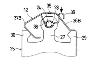
ここで、上記ブリッジ部8、9、10の相互間の開口部11内に配置されたカバースプリング12は、図5〜7によく示されるように、前記パッドピン24の上方を覆うピンカバー部35と、各一対のブレーキパッド22、23を構成する裏板25の一方の肩部29に当接する一対の第1パッド押え部36A,36Bと、前記裏板25の他方の肩部30に当接する一対の第2パッド押え部37A,37Bと、各パッドピン24に下側(ディスクロータの回転中心O側)から係合するピン係止部38と、このピン係止部38に連接された操作部39とを備えている。
【0025】
このカバースプリング12は、ステンレス鋼板などの金属薄板を打抜きおよび曲げ加工することにより一体成形されており、そのピンカバー部35には補強用のリブ部35aが設けられている。また、一対の第1パッド押え部36A,36Bはピンカバー部35から一方向へ下方傾斜するように延ばされた2つの帯状片から、一対の第2パッド押え部37A,37Bは、ピンカバー部35から前記帯状片とは逆方向へ延ばされると共に途中でくの字形に内方へ曲げられた2つの曲げ片からそれぞれ形成されている。さらに、ピン係止部38は、ピンカバー部35の中央部分から一対の第2パッド押え部37A,37Bの間を通してその裏側へ延ばされると共に、途中でピンカバー部35側へU字形に曲げられた帯状の曲げ片から形成されている。一方、操作部39は、前記ピン係止部38を形成する曲げ片を、前記一対の第1パッド押え部36A,36Bの間を通して大きく起立させると共に先端部を逆U字形に曲げた延長片から形成されている。
【0026】
上記カバースプリング12は、そのピン係止部38をパッドピン24に下側から係合させかつその第1、第2パッド押え部36A,36B、37A,37Bを各一対のブレーキパッド22、23を構成する裏板25の両肩部29、30に当接させるように装着される。これにより、各一対の第1、第2パッド押え部36A,36B、37A,37Bには各一対のブレーキパッド22、23を、それらの中心線の交点P側へ付勢する弾発力が発生し、この結果、各一対のブレーキパッド22、23の姿勢が制御されるようになる。
【0027】
上記のように構成したディスクブレーキにおいては、給液口19から各ボア13、14内にブレーキ液が供給されると、二対のピストン15、16が同期して突出し、各一対のブレーキパッド22、23がディスクロータDの両面に圧接される。この時、ディスクロータDが、図2に見て矢印F方向(反時計方向)へ回転していると、ディスク回入側の一対のブレーキパッド22の裏板25の一側面が中央のトルク受け部33のディスク回入側のトルク受け面33aに、ディスク回出側の一対のブレーキパッド23の裏板25の一側面がディスク回出側のトルク受け部32のトルク受け面32aにそれぞれ当接し、制動力が発生する。一方、ディスクロータDが、図2に見て矢印F´方向(時計方向)へ回転していると、ディスク回入側の一対のブレーキパッド23の裏板25の一側面が中央のトルク受け部33のディスク回入側のトルク受け面33bに、ディスク回出側の一対のブレーキパッド22の裏板25の一側面がディスク回出側のトルク受け部31のトルク受け面31aにそれぞれ当接し、同様に制動力が発生する。
【0028】
ここで、制動時のトルク受け部33がブレーキパッドから受ける制動トルクに関して説明すると、制動時にインナ側のピストン16,17とアウタ側のピストンとによりインナ側のブレーキパッド22,23とアウタ側のブレーキパッドとを押圧させることでキャリパ本体1がブリッジ部8,9,10を支点としてディスクロータDの回転軸線方向に拡がるように若干変形することになる。この変形によってブレーキパッドに伝わる押圧力はディスクロータDの径方向内方側よりも外方側の方が大きくなる。そして、ブレーキパッドの摩擦材とディスクロータDとの摩擦係数はディスクロータDの径方向内方も外方も一定であることから、上記押圧力の違いによって制動トルクについてもディスクロータDの径方向内方側よりも外方側の方が大きくなる。このディスクロータDの径方向における制動トルクの違いにより、トルク受け部33は、キャリパ外周側のディスクロータ接線方向の肉厚をある程度厚くする必要があり、また、キャリパ内周側のディスクロータ接線方向の肉厚をある程度薄くすることができる。
【0029】
しかして、本第1の実施の形態においては、各一対のブレーキパッド22、23のパッド中心線C1、C2が、上述したように、前記ディスクロータDの径方向でディスクロータDの回転中心Oに関して前記キャリパ本体1とは反対側の領域の一点Pで交わるように配置しているので、ピストン間のトルク受け部33は、キャリパ外周側の肉厚について制動トルクを十分受けられる程度に減じること、換言すれば、中間のトルク受け部33のディスクロータDの径方向外方の肉厚を減じることができる分、二対のピストン15、16の配列ピッチを小さくすることができ、結果としてキャリパの小型、軽量化を達成できることになる。
【0030】
そして、上記の構成に加えて前記中間のトルク受け部33の左右トルク受け面33a、33bのディスクロータDの径方向で回転中心O側に向う延長線が、前記ディスクロータDの径方向で前記回転中心Oに対して前記キャリパ本体と同じ側のディスクロータDの領域内の一点Qで交わるようになっているので、ディスクロータの回転中心Oに中間のトルク受け部のトルク受け面の延長線の交点を結ばせる場合よりも、中間のトルク受け部33のディスクロータDの径方向内方における肉厚を減じることになり、当該部位におけるブレーキパッドのディスクロータDの接線方向寸法を短くすることでき、ブレーキパッド22、23の摩擦材26のディスクロータDに対する当接面積を有効に確保しつつ、キャリパ本体1のディスクロータDの径方向内方におけるディスクロータDの接線方向寸法を短くしてキャリパの小型、軽量化が達成できる。
【0031】
総じて、上記のように交点P,Qを設定することによって、中間のトルク受け部33の先端角度を適切に設定することが可能となる。すなわち、単にディスクロータの回転中心Oにパッド中心線の交点を結ばせる場合や単にディスクロータの回転中心Oに中間のトルク受け部のトルク受け面の延長線の交点を結ばせる場合よりも中間のトルク受け部33のディスクロータDの接線方向の肉厚を効率的に減じることができ、中間のトルク受け部33の剛性やブレーキパッド22,23の摩擦材26のブレーキロータに対する面積を確保してキャリパ性能を維持しつつ、キャリパの小型、軽量化が達成できる。また、中間のトルク受け部33の先端が欠損することがなく、その長さを十分に確保することができる。
【0032】
本第1の実施の形態においては特に、前記トルク受け部33が、タイボルト6の通るブリッジ部10(突出部5A、5B)に近接する部位に設けられているので、該トルク受け部33の剛性は十分となり、各一対のブレーキパッド22、23の作動が安定して、引摺りの軽減、パッド偏摩耗の低減、ブレーキレバータッチ性の向上等を達成できる。
【0033】
また、本第1の実施の形態においては、交点PはディスクロータDの領域内にあり、中間のトルク受け部33が制動時のブレーキパッド22または23からの制動トルクを受けても変形のないような肉厚となるように設定されている。
【0034】
さらに、本第1の実施の形態のキャリパ本体1においては、中間(ブレーキパッド22、23間)のトルク受け部33の中心線(ディスクロータDの接線方向における肉厚の中心線)C0上に、前記各一対のブレーキパッド22、23の中心線C1、C2の交点Pが存在するようになっている。これにより、ブレーキパッド22、23に同形状のものを使用することが保証されている。
【0035】
前記中間のトルク受け33は、各一対のブレーキパッド22、23に共用される都合上、前記中心線C0上に左右トルク受け面33a、33bの対称中心を置いた二等辺三角形の形態となり、左右トルク受け面33a、33bのディスクロータDの径方向で回転中心O側に向う延長線は、前記ディスクロータDの径方向で前記回転中心Oに対して前記キャリパ本体と同じ側のディスクロータDの領域内の一点で交わるようになっており、中間のトルク受け部33の先端角度が、ディスクロータの回転中心Oにパッド中心線の交点を結ばせる場合よりも小さくなる。
【0036】
また、本第1の実施の形態においては、パッドスプリング12が、ピンカバー部35の裏側に誘導して折曲させたピン係止部38によりパッドピン24に係止される構造となっているので、パッドピン24のほぼ全長がピンカバー部35によって外部から遮蔽され、各一対のブレーキパッド22、23の摺動部に異物が侵入することもなくなって各ブレーキパッド22、23の摺動が安定的に維持される。また、第1、第2パッド押え部36A,36B、37A,37Bが各独立にブレーキパッド22、23の肩部29、30に当接するので、相互に影響を及ぼし合うことがなくなって、各一対のブレーキパッド22、23に作用するパッド押え力は均等となる。しかも、このパッドスプリング12は、ピン係止部38の延長部を起立させて操作部39としているので、この操作部39を介してピン係止部38を押し下げることで、パッドピン24を各ブレーキパッド22、23の被吊り部27の孔28に容易に挿入することができ、各ブレーキパッド22、23の組付けを容易に行うことができる。
【0037】
さらに、本第1の実施の形態においては、トルク受け面31aと33aとが、また、トルク受け面32aと33bとが平行に形成されているので、トルク受け面31aと33aとを、また、トルク受け面32aと33bとを同時に切削加工することが可能となっており、各トルク受け面の加工が容易になっている。
【0038】
図8は、本発明の第2の実施の形態を示したものである。本第2の実施の形態は、第1の実施の形態と同様のキャリパ固定型のディスクブレーキにおいて、そのキャリパを三対のピストン41、42、43を備えた6ピストン対向タイプとして構成している。なお、キャリパ本体1の基本構造は、第1の実施の形態におけるものと特に変わるところがないので、ここでは同一構成要素に同一符号を付し、重複する説明は省略することとする。本第2の実施の形態において、キャリパ本体1内には、前記三対のピストン41、42、43に対応して三対のブレーキパッド44、45、46が配置され、一方、キャリパ本体1には、前記両側のトルク受け部31、32とは別に、前記三対のブレーキパッド44、45、46に共用される2つのトルク受け部47、48が設けられている。なお、ピストン41、42、43およびブレーキパッド44、45、46については、インナ側のみを示し、アウタ側については図示を省略している。
【0039】
しかして、キャリパ本体1は、その中心線(キャリパ中心線)Ccがディスク中心Oを通るように位置決めされている。また、トルク受け部47、48のそれぞれのトルク受け面(図示せず)のディスクロータDの径方向で回転中心O側に向う延長線は、前記ディスクロータDの径方向で前記回転中心Oに対して前記キャリパ本体と同じ側のディスクロータDの領域内の一点で交わるようになっている。さらに、各一対のブレーキパッド44、45、46は、それぞれの中心線C1、C2、C3が、ディスクロータDの片側において前記ディスクロータDの径方向でディスクロータDの回転中心Oに関して前記キャリパ本体1とは反対側の領域の一点Pで交わるように配置されている。この場合、中間(ピストン間)のトルク受け部47、48は、各一対のブレーキパッド44、45、46に共用される都合上、第1の実施の形態におけるトルク受け部33と同様に、前記交点Pを通る線上に左右トルク受け面33a、33bの対称中心を置いた二等辺三角形の形態となる。ただし、本第2の実施の形態においては、三対の対向ピストン41、42、43を備えた6ピストン対向タイプとなっているので、中間の一対のブレーキパッド46の中心線C3は前記キャリパ中心線Ccと一致することになる。
【0040】
また、隣り合ったブレーキパッド44、45の中心線C1、C3の交点は、そのブレーキパッド44、45間のトルク受け部47の中心線C0上にあり、また、隣り合ったブレーキパッド45、46の中心線C2、C3の交点は、そのブレーキパッド44、45間のトルク受け部47の中心線C0’上にある。
【0041】
本第2の実施の形態においては、各トルク受け部47、48のそれぞれのトルク受け面(図示せず)のディスクロータDの径方向で回転中心O側に向う延長線が前記ディスクロータDの径方向で前記回転中心Oに対して前記キャリパ本体と同じ側のディスクロータDの領域内の一点で交わるようになっており、各一対のブレーキパッド44、45、46のパッド中心線C1、C2、C3が、前記ディスクロータDの径方向でディスクロータDの回転中心Oに関して前記キャリパ本体1とは反対側の領域の一点Pで交わるように配置されているので、中間のトルク受け部47、48の先端角度が、ディスクロータの回転中心Oにパッド中心線の交点を結ばせる場合よりも小さくなる。すなわち、ピストン間のトルク受け部47、48は、キャリパ外周側の肉厚を減じても、その先端側が欠損することがなく、その長さが十分に確保され、上記第1の実施の形態と同様にピストン41、42、43の配列ピッチを小さくすることができる。
【0042】
なお、上記第2の実施の形態においては、各一対のブレーキパッド44、45、46のパッド中心線C1、C2、C3が、前記ディスクロータDの径方向でディスクロータDの回転中心Oに関して前記キャリパ本体1とは反対側の領域の全て一点Pで交わるように配置されているが、これに限らず、隣り合ったブレーキパッド44、46の中心線C1、C3の交点と、隣り合ったブレーキパッド45、46の中心線C2、C3の交点とが前記ディスクロータDの径方向でディスクロータDの回転中心Oに関して前記キャリパ本体1とは反対側の領域に存在すれば、これらの交点が異なる点であってもよい。
【0043】
図9は、本発明の第3の実施の形態を示したものである。本第3の実施の形態は、第1の実施の形態と同様のキャリパ固定型のディスクブレーキにおいて、その中間のトルク受け部33’の中心線C0とキャリパ本体1の中心線CcとをディスクロータDの回転方向に(図中右側へ)ずらしたものとして構成している。なお、キャリパ本体1の基本構造は、第1の実施の形態におけるものと特に変わるところがないので、ここでは同一構成要素に同一符号を付し、重複する説明は省略することとする。
【0044】
図9に示すように、本第3の実施の形態において、前記中間のトルク受け33’の左右トルク受け面33a、33bのディスクロータDの径方向で回転中心O側に向う延長線は、前記ディスクロータDの径方向で前記回転中心Oに対して前記キャリパ本体と同じ側のディスクロータDの領域内の一点Qで交わるようになっており、各一対のブレーキパッド22、23は、それぞれの中心線C1、C2が、ディスクロータDの片側において前記ディスクロータDの径方向でディスクロータDの回転中心Oに関して前記キャリパ本体1とは反対側の領域の一点Pで交わるように配置されている。
【0045】
しかして、上述したようにキャリパ本体1の中心線Ccと中間のトルク受け部33'とが一致しない場合でも、中間のトルク受け33’の左右トルク受け面33a、33bのディスクロータDの径方向で回転中心O側に向う延長線が前記ディスクロータDの径方向で前記回転中心Oに対して前記キャリパ本体と同じ側のディスクロータDの領域内の一点Qで交わるように配置され、各一対のブレーキパッド22、23は、それぞれの中心線C1、C2が、ディスクロータDの片側において前記ディスクロータDの径方向でディスクロータDの回転中心Oに関して前記キャリパ本体1とは反対側の領域の一点Pで交わるように配置されていれば、中間のトルク受け部33’の先端角度が、ディスクロータの回転中心Oにパッド中心線の交点を結ばせる場合よりも小さくなる。すなわち、ピストン間のトルク受け部33’は、キャリパ外周側の肉厚を減じても、その先端側が欠損することがなく、その長さが十分に確保される。換言すれば、ピストン間のトルク受け部33’の肉厚を減じることができる分、二対のピストン15、16の配列ピッチを小さくすることができ、結果としてキャリパの小型、軽量化を達成できることになる。
【0046】
なお、上記3つの実施の形態においては、トルク受け部33、47、48、33’の中心線C0、C0’上に各プレーキパッドの中心線の交点P、P’が存在するように説明しているが、必ずしも、トルク受け部33、47、48、33’の中心線C0、C0’上に各プレーキパッドの中心線の交点P、P’が存在する必要はない。
【0047】
また、上記第1及び第3の実施の形態においてはトルク受け部33、33’の中心線がディスクロータDの回転中心Oを通るようになっているが、第2の実施の形態に示されているように、必ずしもトルク受け部33、33’の中心線がディスクロータDの回転中心Oを通るように各トルク受け部33、33’を形成する必要はない。
【0048】
また、上記3つの実施の形態においては、キャリパ固定型でかつキャリパ半割体2Aおよび2Bを連結一体化した2ピース構造のものを示したが、本発明は、キャリパ固定型でかつ1ピース構造として構成しても、あるいはキャリパ浮動型として構成してもよいものである。
【0049】
【発明の効果】
以上、詳細に説明したように、本発明のディスクブレーキによれば、ディスクロータの片側に互いに隣り合って配置されるブレーキパッドの間に位置するトルク受け部の各トルク受け面におけるディスクロータ回転中心側の延長線を、前記ディスクロータの径方向で該ディスクロータの回転中心に対して前記キャリパ本体と同じ側のディスクロータ領域内の一点で交わらせるとともに、該各ブレーキパッドの中心線の交点をディスクロータの回転中心に関して前記キャリパ本体とは反対側の領域に設定するという簡単な改良で、キャリパ本体の剛性を向上させつつ、ブレーキパッドのディスクロータ当接面積を大きくすることができ、また、長さを犠牲にすることなくピストン間のトルク受け部の肉厚を可及的に削減して適正なものすることができるようになり、キャリパの小型、軽量化に寄与するところ大なるものがある。
【図面の簡単な説明】
【図1】本発明の第1の実施の形態としてのディスクブレーキにおけるブレーキパッドの配置状態を示す正面図である。
【図2】本ディスクブレーキの構造を半割状態として示す正面図である。
【図3】本ディスクブレーキの全体構造を示す平面図である。
【図4】本ディスクブレーキの全体構造を示す正面図である。
【図5】本ディスクブレーキにおけるパッドスプリングの形状と組付状態とを示す正面図である。
【図6】パッドスプリングの形状を示す平面図である。
【図7】パッドスプリングの形状を示す側面図である。
【図8】本発明の第2の実施の形態としてのディスクブレーキにおけるブレーキパッドの配置状態を示す正面図である。
【図9】本発明の第3の実施の形態としてのディスクブレーキにおけるブレーキパッドの配置状態を示す正面図である。
【符号の説明】
1 キャリパ本体
2A インナ側キャリパ半割体
2B アウタ側キャリパ半割体
6 タイボルト
8、9、10 ブリッジ部
12 カバースプリング
15,16、41,42,43 ピストン
22,23、44,45,46 ブレーキパッド
24 パッドピン
31,32,33、47,48,33’ トルク受け部
31a、32a、33a、33b トルク受け面
D ディスクロータ[0001]
BACKGROUND OF THE INVENTION
The present invention relates to a disc brake used for braking an automobile, and more particularly to a disc brake suitable for use in a two-wheeled automobile.
[0002]
[Prior art]
As a disc brake for a two-wheeled vehicle, a plurality of pairs of brakes arranged on both sides of the disc rotor corresponding to each piston in a caliper body which is arranged at least on one side of the disc rotor in the rotational direction and has a plurality of pistons built in. The pads are slidably supported, and each pair of brake pads is brought into pressure contact with the disc rotor in accordance with the propulsion of each piston, and the brake pads are supported by the torque receiving portion provided on the caliper body. There are things that generate. In the caliper-fixed type disc brake, the piston is arranged opposite to both sides of the disc rotor, and in the caliper floating type disc brake, the piston is arranged only on one side of the disc rotor.
[0003]
In such a disc brake, each brake pad is generally arranged on one side of the disc rotor so that each pad center line intersects with the center of rotation of the disc rotor, while the torque receiver provided on the caliper body is provided. Among the portions, the torque receiving portion disposed between the pistons has a structure shared by two adjacent brake pads (see, for example, Japanese Utility Model Publication No. 3-53643).
[0004]
[Problems to be solved by the invention]
That is, in the conventional disk brake described above, the torque receiving force between the pistons is used for the convenience of making the intersection of the pad center lines coincide with the rotation center of the disk rotor and sharing the torque receiving part between the pistons with the adjacent brake pads. In order to improve the caliper rigidity, it is necessary to increase the thickness of the caliper outer circumferential side in the disk rotor tangential direction to some extent, and to increase the disc rotor contact area of the brake pad, the caliper inner circumferential side disc Since it is necessary to reduce the thickness of the rotor tangential direction to some extent, it was necessary to take the form of an isosceles triangle with the center of symmetry of the left and right torque receiving surfaces on the line passing through the rotation center of the disk rotor. . In other words, the torque receiving portion between the pistons is considerably thicker on the caliper outer peripheral side due to its unique triangular shape, and the arrangement pitch of the pistons is increased accordingly, the calipers are enlarged, and the weight is also increased. There was a problem.
[0005]
If the thickness of the torque receiving part between the pistons is simply reduced to reduce the arrangement pitch of the pistons, the triangular tip side of the torque receiving part is lost, and the length of the torque receiving part is sufficiently long. This cannot be ensured and causes a new problem that the posture of the brake pad becomes unstable during braking.
[0006]
The present invention has been made in view of the above problems, and the problem is that the thickness of the torque receiving portion between the pistons is reduced as much as possible without sacrificing the length thereof. The object is to provide a disc brake that contributes to the reduction in size and weight of the caliper.
[0007]
[Means for Solving the Problems]
In order to solve the above-mentioned problem, the invention of
[0008]
In the disc brake configured as described above, an extension line on the disc rotor rotation center side on each torque receiving surface of the torque receiving portion located between the brake pads arranged adjacent to each other on one side of the disc rotor is used as the disc brake. In the radial direction of the rotor, it intersects with the center of rotation of the disk rotor at one point in the disk rotor area on the same side as the caliper body, and the intersection of the center lines of the brake pads is defined with respect to the center of rotation of the disk rotor. By setting the area opposite to the main body, the tip angle of the torque receiving part between the pistons on the caliper main body is reduced, increasing the rigidity of the caliper main body and increasing the disc rotor contact area of the brake pad. Moreover, the thickness of the caliper outer peripheral side of the torque receiving portion can be reduced. Even, no longer the front end side of the torque receiving portion is lost.
[0009]
The invention of claim 2 is characterized in that, in the invention of
[0010]
In the disc brake configured as described above, the intersection of the pad center lines of each brake pad is set within the disc rotor region in the region opposite to the caliper body with respect to the center of rotation of the disc rotor in the radial direction of the disc rotor. Therefore, the thickness of the torque receiving portion between the pistons provided in the caliper body can be set appropriately.
[0011]
According to a third aspect of the present invention, in the first or second aspect of the present invention, the intersection of the pad center lines of the brake pads is a torque receiving portion located between the brake pads disposed on one side of the disk rotor. It is characterized by being located on the center line.
[0012]
In the disc brake configured as described above, the intersection of the pad center lines of each brake pad is positioned on the center line of the torque receiving portion located between the brake pads arranged on one side of the disc rotor. Each brake pad can have a similar shape.
[0013]
DETAILED DESCRIPTION OF THE INVENTION
Hereinafter, embodiments of the present invention will be described with reference to the accompanying drawings.
[0014]
1 to 7 show a first embodiment of the present invention. The disc brake as the first embodiment is configured as a caliper fixed type, and the overall structure thereof is as shown in FIGS. In these drawings,
[0015]
The
[0016]
The
[0017]
Further,
[0018]
On the other hand, the inner side
[0019]
Thus, in the caliper
[0020]
In the caliper
[0021]
The intermediate
[0022]
The center lines C1 and C2 of the
[0023]
In the first embodiment, the center line C0 of the intermediate
[0024]
Here, the
[0025]
The
[0026]
The
[0027]
In the disc brake configured as described above, when brake fluid is supplied into the
[0028]
Here, the braking torque received by the
[0029]
Thus, in the first embodiment, the pad center lines C1 and C2 of each pair of
[0030]
In addition to the above configuration, the intermediate torque Receiving part An extension line of the left and right
[0031]
In general, by setting the intersection points P and Q as described above, the tip angle of the intermediate
[0032]
Particularly in the first embodiment, the
[0033]
Further, in the first embodiment, the intersection P is in the region of the disk rotor D, and no deformation occurs even when the intermediate
[0034]
Further, in the caliper
[0035]
The
[0036]
In the first embodiment, the
[0037]
Furthermore, in the first embodiment, since the torque receiving surfaces 31a and 33a and the torque receiving surfaces 32a and 33b are formed in parallel, the torque receiving surfaces 31a and 33a The torque receiving surfaces 32a and 33b can be cut at the same time, and the processing of each torque receiving surface is facilitated.
[0038]
FIG. 8 shows a second embodiment of the present invention. The second embodiment is a caliper-fixed type disc brake similar to the first embodiment, and the caliper is configured as a 6-piston opposed type including three pairs of
[0039]
Thus, the
[0040]
Further, the intersection of the center lines C1, C3 of the
[0041]
In the second embodiment, the extension lines of the torque receiving surfaces (not shown) of the respective
[0042]
In the second embodiment, the pad center lines C1, C2, and C3 of each pair of
[0043]
FIG. 9 shows a third embodiment of the present invention. In the third embodiment, in the caliper-fixed type disc brake similar to the first embodiment, the center line C0 of the intermediate torque receiving portion 33 'and the center line Cc of the
[0044]
As shown in FIG. 9, in the third embodiment, the left and right torque receiving surfaces 33 a and 33 b of the
[0045]
Thus, even when the center line Cc of the
[0046]
In the above-described three embodiments, the description will be made so that the intersection points P and P ′ of the center lines of the brake pads exist on the
[0047]
Further, in the first and third embodiments, the center line of the
[0048]
In the above three embodiments, a caliper fixed type and a two piece structure in which the caliper halves 2A and 2B are connected and integrated are shown. However, the present invention is a caliper fixed type and a one piece structure. Or a caliper floating type.
[0049]
【The invention's effect】
As described above in detail, according to the disc brake of the present invention, the disc rotor rotation center on each torque receiving surface of the torque receiving portion located between the brake pads arranged adjacent to each other on one side of the disc rotor. And an intersection of the center lines of the brake pads at a point in the disk rotor region on the same side as the caliper body with respect to the rotation center of the disk rotor in the radial direction of the disk rotor. With a simple improvement of setting the area opposite to the caliper body with respect to the center of rotation of the disk rotor, it is possible to increase the disk rotor contact area of the brake pad while improving the rigidity of the caliper body. Reduce the thickness of the torque receiving part between the pistons as much as possible without sacrificing the length. Can be as becomes a small caliper, there is a large made where contributes to weight reduction.
[Brief description of the drawings]
FIG. 1 is a front view showing an arrangement state of brake pads in a disc brake according to a first embodiment of the present invention.
FIG. 2 is a front view showing the structure of the disc brake in a half-split state.
FIG. 3 is a plan view showing the overall structure of the disc brake.
FIG. 4 is a front view showing the overall structure of the disc brake.
FIG. 5 is a front view showing the shape and assembly state of a pad spring in the disc brake.
FIG. 6 is a plan view showing the shape of a pad spring.
FIG. 7 is a side view showing the shape of a pad spring.
FIG. 8 is a front view showing an arrangement state of brake pads in a disc brake as a second embodiment of the present invention.
FIG. 9 is a front view showing an arrangement state of brake pads in a disc brake as a third embodiment of the present invention.
[Explanation of symbols]
1 Caliper body
2A inner caliper half
2B Outer caliper halves
6 Tie Bolt
8, 9, 10 Bridge part
12 Cover spring
15, 16, 41, 42, 43 Piston
22, 23, 44, 45, 46 Brake pads
24 pad pins
31, 32, 33, 47, 48, 33 'Torque receiving portion
31a, 32a, 33a, 33b Torque receiving surface
D disk rotor
Claims (3)
前記ディスクロータの片側に配置されたブレーキパッドの間に位置するトルク受け部の各トルク受け面におけるディスクロータ回転中心側の延長線は、前記ディスクロータの径方向で該ディスクロータの回転中心に対して前記キャリパ本体と同じ側のディスクロータ領域内の一点で交わるとともに、
前記ディスクロータの片側において互いに隣り合う前記各ブレーキパッドは、該ブレーキパッドに関する両トルク受け面の間の中心点を通って両ブレーキパッドの間に位置するトルク受け部のトルク受け面に平行なパッド中心線をそれぞれ有しており、前記ディスクロータの径方向で該ディスクロータの回転中心に関して前記キャリパ本体とは反対側の領域の一点でそれぞれのパッド中心線が交わるように配置されることを特徴とするディスクブレーキ。A plurality of pairs of brake pads arranged on both sides of the disk rotor are provided corresponding to the pistons on a caliper body which is arranged at least on one side of the disk rotor in the rotational direction and includes a plurality of pistons. In the disc brake that presses each pair of brake pads to the disc rotor and supports the brake pads in a slidable manner to generate a braking force.
The extension line on the disk rotor rotation center side of each torque receiving surface of the torque receiving portion located between the brake pads arranged on one side of the disk rotor is in the radial direction of the disk rotor with respect to the rotation center of the disk rotor. And intersect at one point in the disc rotor area on the same side as the caliper body,
The brake pads adjacent to each other on one side of the disc rotor are parallel to the torque receiving surface of the torque receiving portion located between the brake pads through a center point between the torque receiving surfaces of the brake pad. Each having a center line, and each pad center line intersects at one point in a region opposite to the caliper body with respect to the rotation center of the disk rotor in the radial direction of the disk rotor. Disc brake.
Priority Applications (1)
| Application Number | Priority Date | Filing Date | Title |
|---|---|---|---|
| JP2002081475A JP3873251B2 (en) | 2001-03-21 | 2002-03-22 | Disc brake |
Applications Claiming Priority (5)
| Application Number | Priority Date | Filing Date | Title |
|---|---|---|---|
| JP2001080493 | 2001-03-21 | ||
| JP2001-80493 | 2001-03-21 | ||
| JP2002-67157 | 2002-03-12 | ||
| JP2002067157 | 2002-03-12 | ||
| JP2002081475A JP3873251B2 (en) | 2001-03-21 | 2002-03-22 | Disc brake |
Publications (2)
| Publication Number | Publication Date |
|---|---|
| JP2003336670A JP2003336670A (en) | 2003-11-28 |
| JP3873251B2 true JP3873251B2 (en) | 2007-01-24 |
Family
ID=29715846
Family Applications (1)
| Application Number | Title | Priority Date | Filing Date |
|---|---|---|---|
| JP2002081475A Expired - Fee Related JP3873251B2 (en) | 2001-03-21 | 2002-03-22 | Disc brake |
Country Status (1)
| Country | Link |
|---|---|
| JP (1) | JP3873251B2 (en) |
-
2002
- 2002-03-22 JP JP2002081475A patent/JP3873251B2/en not_active Expired - Fee Related
Also Published As
| Publication number | Publication date |
|---|---|
| JP2003336670A (en) | 2003-11-28 |
Similar Documents
| Publication | Publication Date | Title |
|---|---|---|
| JPH07745Y2 (en) | Reaction force type disc brake | |
| JP2006057718A (en) | Floating calliper type disk brake | |
| JPS6181021U (en) | ||
| JP3873251B2 (en) | Disc brake | |
| JP4055065B2 (en) | Disc brake | |
| JPS6222679Y2 (en) | ||
| JP4552173B2 (en) | Disc brake | |
| JP4718422B2 (en) | Disc brake | |
| ITMI980062A1 (en) | AXIAL POSITIONING DEVICE OF THE BRAKE BAND FOR DISC BRAKES | |
| JP4028347B2 (en) | Disc brake | |
| JP4263042B2 (en) | Drum brake structure | |
| JPH07746Y2 (en) | Reaction force type disc brake | |
| JP4932071B2 (en) | Disc brake | |
| JPH1163041A (en) | Caliper body for vehicle disc brake | |
| JP4249065B2 (en) | Disc brake | |
| JP4554416B2 (en) | Disc brake | |
| JP3911646B2 (en) | Disc brake | |
| JPS6344587Y2 (en) | ||
| CN218063168U (en) | Vehicle and brake caliper assembly thereof | |
| JPH0650661Y2 (en) | Opposite multi-pot caliper for vehicle disc brakes | |
| JPH03234934A (en) | Multiple pot type disc brake for vehicle | |
| JPH09296836A (en) | Disc brake caliper | |
| JP5510144B2 (en) | Disc brake | |
| JP4818307B2 (en) | Disc brake for radial mount type vehicle | |
| JPH0611368Y2 (en) | Opposed disc brake |
Legal Events
| Date | Code | Title | Description |
|---|---|---|---|
| A621 | Written request for application examination |
Free format text: JAPANESE INTERMEDIATE CODE: A621 Effective date: 20040528 |
|
| A521 | Written amendment |
Free format text: JAPANESE INTERMEDIATE CODE: A821 Effective date: 20040601 |
|
| A711 | Notification of change in applicant |
Free format text: JAPANESE INTERMEDIATE CODE: A712 Effective date: 20041129 |
|
| A977 | Report on retrieval |
Free format text: JAPANESE INTERMEDIATE CODE: A971007 Effective date: 20060628 |
|
| A131 | Notification of reasons for refusal |
Free format text: JAPANESE INTERMEDIATE CODE: A131 Effective date: 20060712 |
|
| A521 | Written amendment |
Free format text: JAPANESE INTERMEDIATE CODE: A523 Effective date: 20060911 |
|
| TRDD | Decision of grant or rejection written | ||
| A01 | Written decision to grant a patent or to grant a registration (utility model) |
Free format text: JAPANESE INTERMEDIATE CODE: A01 Effective date: 20061004 |
|
| A61 | First payment of annual fees (during grant procedure) |
Free format text: JAPANESE INTERMEDIATE CODE: A61 Effective date: 20061013 |
|
| R150 | Certificate of patent or registration of utility model |
Ref document number: 3873251 Country of ref document: JP Free format text: JAPANESE INTERMEDIATE CODE: R150 Free format text: JAPANESE INTERMEDIATE CODE: R150 |
|
| S111 | Request for change of ownership or part of ownership |
Free format text: JAPANESE INTERMEDIATE CODE: R313111 |
|
| FPAY | Renewal fee payment (event date is renewal date of database) |
Free format text: PAYMENT UNTIL: 20091102 Year of fee payment: 3 |
|
| R350 | Written notification of registration of transfer |
Free format text: JAPANESE INTERMEDIATE CODE: R350 |
|
| FPAY | Renewal fee payment (event date is renewal date of database) |
Free format text: PAYMENT UNTIL: 20101102 Year of fee payment: 4 |
|
| FPAY | Renewal fee payment (event date is renewal date of database) |
Free format text: PAYMENT UNTIL: 20111102 Year of fee payment: 5 |
|
| FPAY | Renewal fee payment (event date is renewal date of database) |
Free format text: PAYMENT UNTIL: 20121102 Year of fee payment: 6 |
|
| FPAY | Renewal fee payment (event date is renewal date of database) |
Free format text: PAYMENT UNTIL: 20121102 Year of fee payment: 6 |
|
| FPAY | Renewal fee payment (event date is renewal date of database) |
Free format text: PAYMENT UNTIL: 20121102 Year of fee payment: 6 |
|
| FPAY | Renewal fee payment (event date is renewal date of database) |
Free format text: PAYMENT UNTIL: 20131102 Year of fee payment: 7 |
|
| LAPS | Cancellation because of no payment of annual fees |