JP3874798B2 - Wall panel and joint structure - Google Patents
Wall panel and joint structure Download PDFInfo
- Publication number
- JP3874798B2 JP3874798B2 JP51138297A JP51138297A JP3874798B2 JP 3874798 B2 JP3874798 B2 JP 3874798B2 JP 51138297 A JP51138297 A JP 51138297A JP 51138297 A JP51138297 A JP 51138297A JP 3874798 B2 JP3874798 B2 JP 3874798B2
- Authority
- JP
- Japan
- Prior art keywords
- panel
- groove
- tongue
- foam core
- peripheral
- Prior art date
- Legal status (The legal status is an assumption and is not a legal conclusion. Google has not performed a legal analysis and makes no representation as to the accuracy of the status listed.)
- Expired - Fee Related
Links
Images


Classifications
-
- E—FIXED CONSTRUCTIONS
- E04—BUILDING
- E04B—GENERAL BUILDING CONSTRUCTIONS; WALLS, e.g. PARTITIONS; ROOFS; FLOORS; CEILINGS; INSULATION OR OTHER PROTECTION OF BUILDINGS
- E04B1/00—Constructions in general; Structures which are not restricted either to walls, e.g. partitions, or floors or ceilings or roofs
- E04B1/38—Connections for building structures in general
- E04B1/61—Connections for building structures in general of slab-shaped building elements with each other
- E04B1/6108—Connections for building structures in general of slab-shaped building elements with each other the frontal surfaces of the slabs connected together
- E04B1/612—Connections for building structures in general of slab-shaped building elements with each other the frontal surfaces of the slabs connected together by means between frontal surfaces
- E04B1/6145—Connections for building structures in general of slab-shaped building elements with each other the frontal surfaces of the slabs connected together by means between frontal surfaces with recesses in both frontal surfaces co-operating with an additional connecting element
- E04B1/6154—Connections for building structures in general of slab-shaped building elements with each other the frontal surfaces of the slabs connected together by means between frontal surfaces with recesses in both frontal surfaces co-operating with an additional connecting element the connection made by friction-grip
-
- E—FIXED CONSTRUCTIONS
- E04—BUILDING
- E04B—GENERAL BUILDING CONSTRUCTIONS; WALLS, e.g. PARTITIONS; ROOFS; FLOORS; CEILINGS; INSULATION OR OTHER PROTECTION OF BUILDINGS
- E04B1/00—Constructions in general; Structures which are not restricted either to walls, e.g. partitions, or floors or ceilings or roofs
- E04B1/02—Structures consisting primarily of load-supporting, block-shaped, or slab-shaped elements
- E04B1/14—Structures consisting primarily of load-supporting, block-shaped, or slab-shaped elements the elements being composed of two or more materials
-
- E—FIXED CONSTRUCTIONS
- E04—BUILDING
- E04B—GENERAL BUILDING CONSTRUCTIONS; WALLS, e.g. PARTITIONS; ROOFS; FLOORS; CEILINGS; INSULATION OR OTHER PROTECTION OF BUILDINGS
- E04B1/00—Constructions in general; Structures which are not restricted either to walls, e.g. partitions, or floors or ceilings or roofs
- E04B1/38—Connections for building structures in general
- E04B1/61—Connections for building structures in general of slab-shaped building elements with each other
- E04B1/6108—Connections for building structures in general of slab-shaped building elements with each other the frontal surfaces of the slabs connected together
- E04B1/612—Connections for building structures in general of slab-shaped building elements with each other the frontal surfaces of the slabs connected together by means between frontal surfaces
- E04B1/6145—Connections for building structures in general of slab-shaped building elements with each other the frontal surfaces of the slabs connected together by means between frontal surfaces with recesses in both frontal surfaces co-operating with an additional connecting element
- E04B1/6162—Connections for building structures in general of slab-shaped building elements with each other the frontal surfaces of the slabs connected together by means between frontal surfaces with recesses in both frontal surfaces co-operating with an additional connecting element the connection made by an additional locking key
Landscapes
- Engineering & Computer Science (AREA)
- Architecture (AREA)
- Physics & Mathematics (AREA)
- Electromagnetism (AREA)
- Civil Engineering (AREA)
- Structural Engineering (AREA)
- Finishing Walls (AREA)
- Joining Of Building Structures In Genera (AREA)
- Building Environments (AREA)
- Artificial Fish Reefs (AREA)
- Panels For Use In Building Construction (AREA)
- Load-Bearing And Curtain Walls (AREA)
Abstract
Description
発明の技術分野
本発明は壁パネル、とくに断熱壁パネルに、壁を形成するためかかるパネルを相互に連結する装置に、またパネルを床、屋根およびサブ壁(sub-wall)のような関連する構造物に連結する装置に関するものである。
発明の背景
ハウジングまたは他の構造物を建設するのに使用する、単一の、熱的に有効で、安価な壁パネル構造物を得ることが長期間望まれてきた。多くの試みが提案されたが、多くのかかる壁パネル構造物は外部の支持体または内部の間柱等なしでは構造的建築物パネルとして使用するのに十分強くない。かかる間柱は要素および経費を追加し、しばしばパネルの断熱値または定格を低下する熱的“短絡回路”または橋絡を形成する。
さらに、個々のパネルが相互に連結または結合されるとき、それらは相対的に“引張られ(rack)”または摺動しもしくは捩れ、構造的安定性を低下させる。
さらに、家屋または建築物の壁を建設しかつ形成するのに有用な、構造的に堅固かつ耐久性のある壁構造を製造するため、他のかかるパネルと結合しうる断熱性で、耐候性の壁パネルを得ることがきわめて望まれていた。比較的低収入で、高い人口密度の地域である、世界の多くの地域において、安価で構造的に堅固な家屋を得ることは困難である。住民用の構造的に堅固で、熱的に有効で、安価な囲いを形成するため結合材に適した断熱パネルを得ることは、とくに望ましい。
複数の断熱壁パネルが提案されたが、パネル同志の結合、ならびに対応する他の構造物への取付けは、新しいアイデアおよび改善を必要とする課題である。上記のように、従来の継手および結合概念は十分な本質的特性を欠く、パネルの“R”値を破壊する熱的“短絡”を生ずる、あるいはその両方である。さらに、かかるパネルの構造壁の要素として作用するのに十分な結合強度および剛性のフォームコア壁パネルを得ることが困難であることが発見された。
したがって、本発明の一つの目的は、改善された壁パネルおよび構造容量壁(structual capacity wall)を形成するため同様のパネルを結合する装置を得ることである。
本発明の別の目的は、一つまたはそれ以上のパネルを床に固定する改善された装置を得ることである。
本発明の別の目的は、一つまたはそれ以上のパネルを屋根に固定する改善された装置を得ることである。
本発明の別の目的は、壁取付けまたはパネル結合要素、壁間柱等によるパネルを通る熱移動のない、改善された壁パネルおよび取付け装置を得ることである。
ある種の文化または環境において、事務所またはアパートの境界を形成する、しばしば古い、構造物または壁がすでに存在していることが認められるであろう。これらは時折湿っぽくかつ不均一である。たとえば、世界中のある高人口密度地域において、多数の居住者用構造物は、健康的家庭の基礎として役立つのに不向きな傾斜した、平らでないまたは湿った内部構造壁を有していた。
したがって、本発明の別の目的は、平面の不規則性、湿気または漏洩状態等にもかかわらず、現存するサブ壁に容易に適合しかつ取付け得る機能的壁を得ることである。
発明の要約
これらの目的に対し、本発明の好適な実施例は、補強セメント製パネルで両側を上塗りされた複合フォームコアを有し、複合パネルのフォーム端部はセメント製フェーシングパネルの周辺内側に溝付きである。
好適には、二つの平行な溝が各フォームの端部に設置される。複合パネルを端部方向に結合するため、少なくとも一つの平らな金属条片が、一方のパネル端部の溝および隣接するパネル端部の向合った溝に挿入され、両方の隣接するパネルの端部によって囲まれた舌片を形成する。ねじまたは他の適当な固定具が、セメント製パネル、介在するフォームを通して舌片内に取付けられ、それにより二つの隣接するパネルを一緒に保持する。舌片自体、それが挿入された後移動するのを阻止するため、逆とげがあるかまたは、溝のフォーム端部に貫入するため、返りとして作用する鋭く折曲げられた端部を有し、それにより組立てを促進する。
好適には、舌片が各当接パネルの各隣接溝内に垂直に延在して配置され、しかして二つの舌片はそれぞれ当接パネルの端部または面に挿入される。
パネルを床上に設置するとき、直立脚部を備えたU字形溝材が床に固定され、パネルは溝材上に下降せしめられ、溝材の脚部はパネルのフォーム面または端部の二つの平行溝内に上方に延在する。
複合パネルの上端は、パネルの上端の上にかつそれに沿って延在する下向きに配置されたU字形溝材によって完成される。
いずれの場合にも、その端部における、パネル結合舌片内へのねじは、そのように製造されたパネル壁装置にさらに剛性を付加するため、それぞれ、床取付けU字形溝材またはパネルキャップを通って延在する。
一つのパネルが他のパネルの上に設置されるとき、水平に隣接する溝に設置された水平な結合舌片が、パネルのいろいろな高さの壁を得るため使用される。
かかる複合構造の結果はまったく素晴らしく、このように結合されたパネルは、たとえば“引張り”にさらされない負荷支持壁を提供する。すなわち、このようなパネルで作られた、例えば、家屋が風をうけたとき、各パネルが捩られまたは引張られる。
さらに、パネル壁に貫通間柱またはパネルの間の継手が存在しないことが認められるであろう。しかして、フォームはパネルを通る熱伝達に対する連続した障壁を形成し、固定具−間柱ブラケット等のようないかなる貫通構造物によっても妥協されない。したがって、セメント製パネルフェーシングを備えた厚さ7.62cm(3インチ)のフォームパネルは約R18の断熱値の壁を提供するのに対してフォームまたは原綿(batting)の、普通のツーバイフォー間柱付き壁は、最大R14の定格である。
長い連結片、および下記に記載されるクリップが、パネル内のフォームの強度に依存し、パネルのR値と妥協しないことが認められるであろう。
一つの変形において、結合材または舌状部材はそれらの上端に折曲げフランジを有し、C字形溝材は除去されている。これらの上方フランジは、垂直な壁パネルを屋根構造に結合するため、屋根パネルまたは構造物の底部にねじ込むことができる。
別の実施例において、本発明はかかるパネルを現存する壁またはサブ壁構造に固定することを意図している。たとえば、複合フォームパネルはフォームの両側が補強セメント製パネルで上塗りされるかまたは片側だけをかかるパネルで上塗りされることを意図している。いずれの場合にも、溝がパネル周囲のフォーム端部に切込まれ、Z字形クリップは、たとえば一方の脚部を溝に挿入し、他方の脚部を壁に相互連結するため後方に延長して、設置される。その脚部は曲げて壁と面一にしてそこに固定されるか、または、現存する壁またはサブ壁のいかなる変化にも対応するシムを備えた平らなパネル壁を形成するように、壁から外方に詰め木を入れられることができる。さらに、同じZ字形クリップは、パネルの上端を屋根または他の支持構造物に固定するため、パネルの上端に利用することができる。
この実施例の変形において、L字形クリップが利用され、短い脚部はパネルの溝内に延在し、長い脚部は後方に延在する。その長い脚部は、たとえば、現存する壁、背壁または他の支持体に固定された補完的L字形クリップに連結され、二つのL字形クリップの間の相互係合は、たとえば、調節可能であるかまたはタッピングねじの使用によって決定され、パネルクリップの長い脚部と支持壁上のL字形クリップの短い又は長い脚部との間の十分な遊びは、現存する壁またはサブ壁の非平面的変化に適合するため十分な調節を可能にする。しかしてこの壁の取付けは、装置内にいかなる熱的短絡も存在しないように、パネルの断熱特性と妥協することなく達成される。
したがって、本発明は、家屋および建築物のような囲い用の、堅固な耐候性壁を建設する際に使用するのに適した、断熱性のある構造的パネルを提供するものである。同時に本発明は、別の方法では適当に上塗りすることのできない、不規則性および湿気等にもかかわらず、現存する壁またはサブ壁に取付けるのに適した断熱性パネルを提供するものである。
【図面の簡単な説明】
これらのおよび他の目的および利点は、本発明の好適な実施例に関する下記の記載から、また図面から容易に明らかになるであろうが、図面の中で、
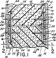
図1は、本発明による二つの舌片または連結片およびねじまたは固定具によって結合された二つのパネルの断面平面図;
図2は、下端における床へのパネル結合装置を示す一つのパネルの断面図;
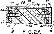
図2Aは、上端にパネルキャップを有する一つのパネルの断面図;
図2Bは、パネル底部における一つの別の舌片および溝材の連結を示す斜視図;
図3は、一つのパネルの端部および二つの対応するパネル舌片の展開図;
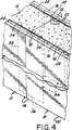
図4は、二つの舌片によって結合された二つのパネルの破断図;
図5は90°のコーナーにおける二つのパネルの結合装置を示す平面図:
図6および図7は図2と同様であるが屋根取付けフランジを有する舌片を示す断面図;
図8は二重フェーシングパネルおよび本発明による任意のシムを備えたZ字形壁取付けクリップの図;
図9は図8と同様であるが、片側フェーシングパネルおよび本発明の別の実施例による二つのL字形壁取付けクリップの図;そして
図10は、図3と同様であるが、別の屋根取付クリップを示す図。
発明の詳細な説明
図面を詳細に参照すると、図示された一対の当接複合壁パネル10は、図1および図4において、本発明の一実施例に従って結合されている。各壁パネル10はフォームコア12を有し、フォームコア12はその反対側側面16に接着結合された補強セメント製フェーシングパネル14を有する。好適には7.62cm(3インチ)の厚さのフォームコア12は上端18、下端20および一対のパネル側端22を有し、各周端は、下記に一層詳細に記載されるように、端部18,20および22(ならびに図示しない遠い端部)内で延在する、2.54〜1.27cm(1〜1/2インチ)の一対の長いかつ平行な溝24(図3参照)を有する。好適な実施例において、一対の長い舌片または連結部材26が、下記に一層詳細に開示されるように、本発明に従って壁パネルを結合するため、当接壁パネル10の反対側端部の溝24に垂直に挿入されている。
図3にもっとも明瞭に示されたように、各壁パネル10はセメント製フェーシングパネル14に隣接するフォームコア12の反対側側面から約1.27〜2.54cm(1/2〜1インチ)に端部18,20および22内で延在する平行な溝を備えるのが好適である。“UTIL−A−CRETE”の商標名で市販されている、補強セメント製フェーシングパネル14の構造および製造法は、米国特許第4203788号、同4428952号、同4420295号、再発行特許第32037号、同32038号および同31921号に詳細に記載され、それらすべてをここに参照する。
図1および図4に示されるように、一対の舌状部材26は当接壁パネル10の反対側端部の溝24に垂直に挿入され、壁パネルはさらに当接パネル10を一緒に保持するため、セメント製フェーシングパネル14、介在フォーム部分30を通り、舌状部材内に延在する、固定具28(図1参照)によってさらに固定されている。各舌状部材26は、舌状部材の前面36から内方かつ後方に延在する鋭く折曲げられた端部または返り34によって画定された側端部32を備えている。舌状部材26が溝24内に挿入されるとき、それらが当接壁パネル10の壁に挿入されてしまった後、舌状部材が移動することを防止するため、返り34が溝に隣接するフォームコア12内に貫入することが認められるであろう。このようにして、舌状部材26は当接壁パネル10の側端22によって包囲され、ねじ等のような固定具28が、本発明に従って壁パネルを接合するため、上記のように各側面16上の補強セメント製フェーシングパネル14を通って挿入される。壁パネル10がいろいろな高さのパネル壁を得るため上に重ねて結合され、舌状部材26が水平に当接パネルの各対向する上下端の溝に挿入しうることが認められるであろう。
図2を参照すると、壁パネル10を床40に取付けるU字形脚部溝材38が図示されている。一実施例において、各脚部溝材38は直立する脚部またはフランジ42を備え、それらは各フランジに垂直なウェブ44によって結合されている。ボルト46または他の適当な固定具が、脚部溝材38を床40に固定するため、ウェブ44を通って床40に挿入されている。少なくとも一つの壁パネル10が脚部溝材38上に下降せしめられ、直立フランジ42は壁パネルの下端20に形成された各平行溝24内に延在する。壁パネル10を脚部溝材38に固定するため、好適には、固定具48がセメント製フェーシングパネル14、(図示しない)舌状部材26を通って、フランジ42内に挿入される。図2Bに示された変形例において、各舌状部材26はウェブ44に沿って延在するタブ50を備え、各タブは孔51を通って(図示しない)床内に延在する(図示しない)ボルトまたは他の適当な手段によってウェブに固定されている。
図2Aを参照すると、U字形キャップパネル52が、一実施例において、壁パネル10の上端18を完成するため設けられている。キャップパネル52は、一対の垂下する脚部またはフランジ54を有し、それらは各フランジに垂直なウェブ56によって接合されている。キャップパネル52は壁パネル10の上端18に挿入され、垂下フランジ54は上端に形成された各溝24内に延在する。キャップパネル52を壁パネル10に固定するため、好適には、ファスナ48がセメント製フェーシングパネル14、(図示しない)舌状部材を通ってフランジ54内に挿入される。
図5を参照すると、コーナー58において結合された一対の当接壁パネル10が示されている。各壁パネル10は他方の壁パネルの傾斜した端部に当接する傾斜した端部60を備え、またさらに各傾斜した端部内に延在する一対の平行な溝24′を備えている。当接する傾斜端部60は、コーナー58において、当接する壁パネル10のそれぞれ整合した溝24′内に挿入される一対の角度をなす舌状部材62を介して結合される。舌状部材62がコーナー58とほぼ同じ角度のベンドまたは角部を備えていることが認められるであろう。上記の舌状部材24によるように、角度をなす舌状部材62は、角度をなす舌状部材の前面68から内方かつ後方に延在する、鋭く折曲げられた端部または返り66によって画定された横方向端部64を有する。当接壁パネル10をコーナー58において一緒に保持するため、(図示しない)固定具が、セメント製フェーシングパネル14、介在するフォーム部分30を通り、角度をなす舌状部材62内に延在する。
図6および図7に示された好適な実施例において、各舌状部材26は、舌状部材26および対応する壁パネル10を屋根部材74に固定するため、上端18に平行に曲がりかつセメント製フェーシングパネル14に向かって外方に延在する、タブ72を有する上端70を備えている。図6に示された一実施例において、各舌状部材26の各タブ72は、固定具78により屋根部材74の下面76に固定されている。図7に示された別の実施例において、タブ72′は壁パネル10から離れて外方に延在し、かつ固定具78によって屋根部材74の上面80に固定されている。
さて図8を参照すると、図示された壁パネル10は、本発明の一実施例に従ってサブ壁または背壁82に結合されている。設けられたZ字形の一体の壁取付けクリップまたはブラケット84は、二つの平行な、離れた平面内にある一対の脚部86および88を有し、それらは各脚部に垂直な一体のウェブ90により接合されている。脚部86はサブ壁82にもっとも近い平行な溝の一つ24に挿入され、後方に延在する脚部88は固定具92によりサブ壁に直接に、もしくは任意のシム94を介して壁に間接的に結合される。シム94を現存するサブ壁82の非平面的不規則性に対応するため設けうることが認められるであろう。溝24に挿入される脚部85が、舌状部材26に関連して上記に記載されたように、溝に隣接するフォームコア内に貫入するため、(図示しない)鋭く曲げられた端部または返りを備え得ることが理解されよう。図示されてはいないが、ブラケット84は適当な固定具を介して壁パネル10に固定され、固定具は壁パネル10をサブ壁82に保持するため、セメント製フェーシングパネル14、介入するフォーム部分を通り、そして脚部86内に延在している。
図9に示された他の実施例において、図示された壁パネル10′は、一対の共働するL字形壁取付けクリップまたはブラケット96および98を介してサブ壁または背壁82に固定されている。この実施例において、壁パネル10′はフォームコア12の側面の一つ16に固定されたセメント製フェーシングパネル14を有し、フォームコアの他の側面はサブ壁82に隣接している。壁取付けクリップ96は互いに垂直な一対の脚部100および102を有する。脚部100は、サブ壁82にもっとも近い側壁16に隣接する平行な溝24の一つに挿入され、後方に延在する脚部102は、現存するサブ壁または背壁82に固定される補完的L字形壁取付けクリップまたはブラケット98に固定されている。そうでなければ、脚部100はフェーシング14にもっとも近いパネル溝に挿入され、脚部102はブラケット98に接合するため延在せしめられている。壁82に固定された補完的ブラケット98は、互いに垂直な一対の脚部104および106を有し、脚部104は固定具108または他の適当な手段を介して壁82に固定されている。脚部102および106はそれぞれ長い孔110を有し、タッピングねじ112は、壁取付けクリップ96および98の脚部102および106の間の調節可能な相互係合を生ずるため、脚部の孔110を通って挿入される。このようにして、壁パネル10′を非平面的不規則性を有するサブ壁82に固定するための調節が得られる。溝24内に挿入された脚部100が、舌状部材26に関連して上記に記載されたような、溝に隣接するフォームコア内に貫入するため、(図示しない)鋭く折曲げられた端部または返りを備え得ることが理解されよう。図示されていないが、ブラケット96は、壁パネルをサブ壁82に保持するため、フォーム部分30を通って脚部100内に延在する適当な固定具を介して壁パネル10′に固定される。
図10に示されたように、一体のZ字形屋根取付けクリップまたはブラケット114が、壁パネル10を(図示しない)屋根部材に固定するため設けられている。屋根取付けクリップ114は、二つの平行な、離れた平面内にありかつ各脚部に垂直な一体のウェブ120によって結合された、一対の脚部116および118を有する。脚部116は平行な溝24の一方に挿入され、ウェブ120は壁パネル10の上端18に平行に延在している。上方に延在する脚部118は、壁パネルの上端に固定された屋根部材内に延在する(図示しない)固定具をうけ入れる孔122を備えている。
本発明は種々の実施例の記載によって説明され、かつこれらの実施例はかなり詳細に記載されたが、制限する、またはいずれにしても添付の請求の範囲をかかる細部に制限することは出願人の意図ではない。付加的利点および変形が、この技術に通じた人々にとって容易に達成されるであろう。したがって、本発明はその広い観点において、図示しかつ説明された特殊な細部および説明的事例に限定されるものではない。したがって、本発明の範囲から離れることなしにかかる細目からの離間をなしうるものである。 TECHNICAL FIELD OF THE INVENTION The present invention relates to a wall panel, in particular a thermal insulation wall panel, to an apparatus for interconnecting such panels to form a wall, and to the panel, floor, roof and sub-wall. It is related with the apparatus connected with such a related structure.
Background of the Invention It has long been desired to obtain a single, thermally effective and inexpensive wall panel structure for use in constructing a housing or other structure. Although many attempts have been proposed, many such wall panel structures are not strong enough to be used as structural building panels without external supports or internal studs or the like. Such studs add elements and expense and often form a thermal “short circuit” or bridge that reduces the insulation value or rating of the panel.
Furthermore, when individual panels are connected or joined together, they are relatively “racked” or slid or twisted, reducing structural stability.
In addition, to produce a structurally robust and durable wall structure that is useful for building and forming the walls of a house or building, it is insulated and weatherproof that can be combined with other such panels. It was highly desirable to obtain wall panels. In many parts of the world, a relatively low-income, high-population area, it is difficult to obtain inexpensive and structurally robust houses. It is particularly desirable to have a thermal insulation panel suitable for bonding materials to form a structurally robust, thermally effective, inexpensive enclosure for the public.
Although multiple insulated wall panels have been proposed, joining the panels together and attaching them to other corresponding structures is a challenge that requires new ideas and improvements. As noted above, conventional coupling and coupling concepts lack sufficient intrinsic properties and / or result in a thermal “short circuit” that destroys the “R” value of the panel. Furthermore, it has been found difficult to obtain foam core wall panels with sufficient bond strength and rigidity to act as structural wall elements of such panels.
Accordingly, one object of the present invention is to provide an apparatus for combining similar panels to form improved wall panels and structural capacity walls.
Another object of the invention is to obtain an improved device for securing one or more panels to the floor.
Another object of the invention is to obtain an improved device for securing one or more panels to a roof.
Another object of the present invention is to obtain an improved wall panel and mounting device that is free of heat transfer through the panel by wall mounting or panel coupling elements, wall studs, and the like.
It will be appreciated that in some cultures or environments, there are already old structures or walls that form the boundaries of an office or apartment. These are sometimes moist and uneven. For example, in one highly populated area around the world, many residential structures have sloped, uneven or moist internal structural walls that are unsuitable to serve as the basis for a healthy home.
Accordingly, another object of the present invention is to obtain a functional wall that can easily fit and attach to existing sub-walls, despite planar irregularities, moisture or leakage conditions, and the like.
SUMMARY OF THE INVENTION For these purposes, a preferred embodiment of the present invention has a composite foam core coated on both sides with a reinforced cement panel, the foam end of the composite panel being a cement facing panel. There is a groove inside the periphery of.
Preferably, two parallel grooves are installed at the end of each foam. To join the composite panel in the end direction, at least one flat metal strip is inserted into the groove on one panel end and the opposite groove on the adjacent panel end, and the edges of both adjacent panels A tongue piece surrounded by the part is formed. Screws or other suitable fasteners are mounted in the tongue piece through the cement panel, intervening foam, thereby holding the two adjacent panels together. The tongue itself has a sharply bent end that acts as a return to prevent it from moving after it has been inserted, or is barbed or penetrates into the foam end of the groove; This facilitates assembly.
Preferably, the tongues are arranged vertically extending in each adjacent groove of each abutment panel, so that the two tongue pieces are respectively inserted into the ends or faces of the abutment panel.
When installing the panel on the floor, a U-shaped groove with upright legs is fixed to the floor, the panel is lowered onto the groove, and the legs of the groove are two of the foam face or end of the panel It extends upward into the parallel grooves.
The upper end of the composite panel is completed by a U-shaped groove disposed downwardly extending over and along the upper end of the panel.
In any case, the screw in the panel coupling tongue at its end adds a floor mounted U-shaped groove or panel cap, respectively, to add more rigidity to the panel wall device so manufactured. Extending through.
When one panel is installed on top of another, horizontal coupling tongues installed in horizontally adjacent grooves are used to obtain the various height walls of the panel.
The result of such a composite structure is quite nice and the panel thus bonded provides a load bearing wall that is not exposed to, for example, “tension”. That is, each panel made of such a panel, for example, when the house is winded, is twisted or pulled.
Furthermore, it will be appreciated that there are no through studs or joints between panels in the panel wall. Thus, the foam forms a continuous barrier to heat transfer through the panel and is not compromised by any penetrating structure such as a fixture-post bracket or the like. Thus, a foam panel with a thickness of 7.62 cm (3 inches) with cement panel facing provides a wall with an insulation value of about R18, whereas an ordinary two-by-four studded wall of foam or batting Is a rating of maximum R14.
It will be appreciated that the long connecting pieces, and the clips described below, depend on the strength of the foam in the panel and do not compromise the R value of the panel.
In one variant, the binder or tongue has a bent flange at their upper end and the C-shaped channel is removed. These upper flanges can be screwed into the bottom of the roof panel or structure to join the vertical wall panels to the roof structure.
In another embodiment, the present invention contemplates securing such panels to existing wall or subwall structures. For example, composite foam panels are intended to be overcoated with reinforcing cement panels on both sides of the foam or overcoated with such panels only on one side. In either case, the groove is cut into the foam edge around the panel, and the Z-clip extends backwards, for example, to insert one leg into the groove and interconnect the other leg to the wall. Installed. The legs can be bent and secured to the wall flush with it, or from the wall to form a flat panel wall with shims that accommodates any changes in existing walls or sub-walls. Can be padded outside. Further, the same Z-shaped clip can be utilized at the top of the panel to secure the top of the panel to a roof or other support structure.
In a variation of this embodiment, an L-shaped clip is utilized, with the short legs extending into the panel grooves and the long legs extending rearward. The long legs are connected to a complementary L-shaped clip secured to an existing wall, back wall or other support, for example, and the interengagement between the two L-shaped clips is adjustable, for example. Sufficient play between the long leg of the panel clip and the short or long leg of the L-shaped clip on the support wall is determined by the use of a tapping screw or non-planar of the existing wall or subwall Allow sufficient adjustment to adapt to change. The lever mounting is thus achieved without compromising the thermal insulation properties of the panel so that there is no thermal short circuit in the device.
Accordingly, the present invention provides a thermally insulating structural panel suitable for use in the construction of rigid weatherproof walls for enclosures such as houses and buildings. At the same time, the present invention provides an insulating panel suitable for mounting on existing walls or sub-walls, despite irregularities and moisture, etc., which cannot be properly overcoated otherwise.
[Brief description of the drawings]
These and other objects and advantages will be readily apparent from the following description of preferred embodiments of the invention and from the drawings, in which:
1 is a cross-sectional plan view of two panels joined by two tongues or connecting pieces and screws or fasteners according to the invention;
FIG. 2 is a cross-sectional view of one panel showing the panel coupling device to the floor at the lower end;
2A is a cross-sectional view of one panel having a panel cap on the top;
FIG. 2B is a perspective view showing the connection of one other tongue and groove at the bottom of the panel;
FIG. 3 is an exploded view of one panel end and two corresponding panel tongues;
FIG. 4 is a cutaway view of two panels joined by two tongues;
FIG. 5 is a plan view showing a coupling device for two panels at a 90 ° corner:
6 and 7 are cross-sectional views similar to FIG. 2, but showing a tongue having a roof mounting flange;
FIG. 8 is a view of a Z-shaped wall mounting clip with a double facing panel and an optional shim according to the present invention;
FIG. 9 is similar to FIG. 8, but with one side facing panel and two L-shaped wall mounting clips according to another embodiment of the present invention; and FIG. 10 is similar to FIG. 3, but with another roof mounting. The figure which shows a clip.
DETAILED DESCRIPTION OF THE INVENTION Referring to the drawings in detail, a pair of abutting
As most clearly shown in FIG. 3, each
As shown in FIGS. 1 and 4, a pair of
Referring to FIG. 2, a
Referring to FIG. 2A, a U-shaped cap panel 52 is provided in one embodiment to complete the
Referring to FIG. 5, a pair of
In the preferred embodiment shown in FIGS. 6 and 7, each
Referring now to FIG. 8, the illustrated
In another embodiment shown in FIG. 9, the illustrated wall panel 10 'is secured to the sub-wall or
As shown in FIG. 10, an integral Z-shaped roof mounting clip or
While the invention has been described in terms of various embodiments, and these embodiments have been described in considerable detail, it is the applicant's responsibility to limit or in any way limit the appended claims to such details. Is not the intention. Additional benefits and variations will be readily achieved for those skilled in the art. The invention in its broader aspects is therefore not limited to the specific details and illustrative examples shown and described. Therefore, it is possible to make a separation from the details without departing from the scope of the present invention.
Claims (11)
(ロ)前記溝(24)が前記側面(16)に平行である前記(イ)の建築物パネル、(B) The building panel of (a), wherein the groove (24) is parallel to the side surface (16),
(ハ)前記フォームコア(12)の各側面にセメント製フェーシング(14)が存在する前記(イ)又は(ロ)の建築物パネル、(C) The building panel according to (A) or (B), wherein a cement facing (14) is present on each side of the foam core (12),
(ニ)前記パネルが、四つの周端(18、20、22)を有し、かつ、前記四つの周端のそれぞれに延在する二つの溝(24)を備えている前記(イ)から(ハ)のいずれかの建築物パネル、(D) From the above (a), the panel has four peripheral ends (18, 20, 22) and has two grooves (24) extending to each of the four peripheral ends. (C) any building panel,
(ホ)前記各溝(24)が互いに対するよりもパネルの側面により近い前記(イ)から(ニ)のいずれかの建築物パネル、(E) The building panel of any one of (i) to (d), wherein each groove (24) is closer to the side of the panel than to each other.
(ヘ)各溝(24)は前記パネルの全周端(18、20、22)に沿って延在している前記(イ)から(ホ)のいずれかの建築物パネル、(F) Each of the grooves (24) extends along the entire peripheral edge (18, 20, 22) of the panel.
壁構造を画定する二つの隣接するパネル(10)であって、前記(イ)から(ヘ)のパネルのいずれかによるパネルの組み合わせであって、各パネルの二つの反対側周端(18、20、22)は平行であり、前記組み合わせが各隣接するパネルの共働する及び整列した各溝(24)に設置された少なくとも一つの相互連結舌状部材(26)を有し、各共働する溝(24)は互いに整列及び整合し前記舌状部材(26)を受け入れて前記パネルを一緒に結合し、二つの舌状部材(26)はそれぞれ他のパネルの周端(18、20、22)に隣接するパネルの各周端(18、19、20)における二つの別々の平行な溝(24)に整合していて、Two adjacent panels (10) defining a wall structure, which is a combination of panels according to any of the panels (a) to (f), wherein two opposite peripheral edges (18, 20, 22) are parallel and the combination has at least one interconnecting tongue (26) installed in each cooperating and aligned groove (24) of each adjacent panel, each cooperating The grooves (24) align and align with each other to receive the tongue (26) and couple the panels together, and the two tongues (26) are respectively connected to the peripheral edges (18, 20,. 22) aligned with two separate parallel grooves (24) at each peripheral edge (18, 19, 20) of the panel adjacent to
パネル(10)の下に水平に配置されかつ少なくとも一つのパネル(10)の下端(20)に配置された溝(24)内において上方に延在する少なくとも一つのフランジを備えたU字型脚部溝材(38)をさらに備え、溝(24)内に各舌状部材(26)が配置され、U-shaped leg with at least one flange disposed horizontally below the panel (10) and extending upwardly in a groove (24) disposed at the lower end (20) of the at least one panel (10) A groove member (38), and each tongue-like member (26) is disposed in the groove (24);
前記パネル(10)、溝材(38)及び舌状部材(26)を一緒に保持するため前記パネル(10)のセメント製フェーシング(14)を通り、前記溝材のフランジ(42)内にそして前記舌状部材(26)内に延在する固定具(48)をさらに備えたパネルの組合わせ。To hold the panel (10), the groove (38) and the tongue (26) together, through the cement facing (14) of the panel (10), into the flange (42) of the groove and A combination of panels further comprising a fixture (48) extending into the tongue (26).
(ロ)前記溝(24)が前記側面(16)に平行である前記(イ)の建築物パネル、(B) The building panel of (a), wherein the groove (24) is parallel to the side surface (16),
(ハ)前記フォームコア(12)の各側面にセメント製フェーシング(14)が存在する前記(イ)又は(ロ)の建築物パネル、(C) The building panel according to (A) or (B), wherein a cement facing (14) is present on each side of the foam core (12),
(ニ)前記パネルが、四つの周端(18、20、22)を有し、かつ、前記四つの周端のそれぞれに延在する二つの溝(24)を備えている前記(イ)から(ハ)のいずれかの建築物パネル、(D) From the above (a), the panel has four peripheral ends (18, 20, 22) and has two grooves (24) extending to each of the four peripheral ends. (C) any building panel,
(ホ)前記各溝(24)が互いに対するよりもパネルの側面により近い前記(イ)から(ニ)のいずれかの建築物パネル、(E) The building panel of any one of (i) to (d), wherein each groove (24) is closer to the side of the panel than to each other.
(ヘ)各溝(24)は前記パネルの全周端(18、20、22)に沿って延在している前記(イ)から(ホ)のいずれかの建築物パネル、(F) Each of the grooves (24) extends along the entire peripheral edge (18, 20, 22) of the panel.
壁構造を画定する二つの隣接するパネル(10)であって、前記(イ)から(ヘ)のパネルのいずれかによるパネルの組み合わせであって、各パネルの二つの反対側周端(18、20、22)は平行であり、前記組み合わせが各隣接するパネルの共働する及び整列した各溝(24)に設置された少なくとも一つの相互連結舌状部材(26)を有し、各共働する溝(24)は互いに整列及び整合し前記舌状部材(26)を受け入れて前記パネルを一緒に結合し、二つの舌状部材(26)はそれぞれ他のパネルの周端(18、20、22)に隣接するパネルの各周端(18、19、20)における二つの別々の平行な溝(24)に整合していて、Two adjacent panels (10) defining a wall structure, which is a combination of panels according to any of the panels (a) to (f), wherein two opposite peripheral edges (18, 20, 22) are parallel and the combination has at least one interconnecting tongue (26) installed in each cooperating and aligned groove (24) of each adjacent panel, each cooperating The grooves (24) align and align with each other to receive the tongue (26) and couple the panels together, and the two tongues (26) are respectively connected to the peripheral edges (18, 20,. 22) aligned with two separate parallel grooves (24) at each peripheral edge (18, 19, 20) of the panel adjacent to
ウェブ(56)及び前記パネルの各側のセメント製フェーシング(14)に沿って垂下する二つのフランジ(54)を有するU字型キャップ溝材(52)と、前記溝材(52)を前記パネル(10)に保持するため前記フェーシング(14)を通り、前記フランジ(54)にそして前記舌状部材(26)内に延在する固定具(48)とをさらに備えた、パネルの組合わせ。A U-shaped cap groove member (52) having two flanges (54) depending on a web (56) and a cement facing (14) on each side of the panel, and the groove member (52) on the panel. A combination of panels further comprising a fastener (48) extending through the facing (14) to hold in (10), to the flange (54) and into the tongue (26).
(ロ)前記溝(24)が前記側面(16)に平行である前記(イ)の建築物パネル、(B) The building panel of (a), wherein the groove (24) is parallel to the side surface (16),
(ハ)前記フォームコア(12)の各側面にセメント製フェーシング(14)が存在する前記(イ)又は(ロ)の建築物パネル、(C) The building panel according to (A) or (B), wherein a cement facing (14) is present on each side of the foam core (12),
(ニ)前記パネルが、四つの周端(18、20、22)を有し、かつ、前記四つの周端のそれぞれに延在する二つの溝(24)を備えている前記(イ)から(ハ)のいずれかの建築物パネル、(D) From the above (a), the panel has four peripheral ends (18, 20, 22) and has two grooves (24) extending to each of the four peripheral ends. (C) any building panel,
(ホ)前記各溝(24)が互いに対するよりもパネルの側面により近い前記(イ)から(ニ)のいずれかの建築物パネル、(E) The building panel of any one of (i) to (d), wherein each groove (24) is closer to the side of the panel than to each other.
(ヘ)各溝(24)は前記パネルの全周端(18、20、22)に沿って延在している前記(イ)から(ホ)のいずれかの建築物パネル、(F) Each of the grooves (24) extends along the entire peripheral edge (18, 20, 22) of the panel.
前記(イ)から(ヘ)のいずれかに記載された複数のパネル(10)を有する囲いであって、各パネル(10)の各側にセメント製フェーシング(14)が設けられ、前記パネル(10)が隣接するパネル(10)と周端を当接して配置され、各当接周端(18、20、22)にフォームコア(12)中の二つの別々の平行な溝(24)が設けられ、前記周端(18、20、22)の溝(24)が前記各パネルにおける隣接する共働する溝(24)と整列しかつ整合し、長い舌状部材(26)が隣接する溝(24)に配置され、舌状部材(26)がパネル(10)を構造的に一緒に固定するため二つのパネル(10)の周端の間に延在し、固定具(28)が前記舌状部材(26)及びパネル(10)を一緒にボルト止めするため前記フェーシング(14)を通って前記舌状部材(26)内に延在していて、An enclosure having a plurality of panels (10) described in any one of (a) to (f), wherein a cement facing (14) is provided on each side of each panel (10), 10) are arranged in abutment with adjacent panels (10) and peripheral edges, each contact peripheral edge (18, 20, 22) having two separate parallel grooves (24) in the foam core (12). Provided, the groove (24) of the peripheral edge (18, 20, 22) is aligned and aligned with the adjacent cooperating groove (24) in each panel, and the long tongue-like member (26) is an adjacent groove. (24), the tongue (26) extends between the peripheral edges of the two panels (10) to structurally secure the panel (10) together, and the fastener (28) Said face for bolting together the tongue (26) and the panel (10) It extends in the tongue (26) in through the grayed (14),
前記パネル(10)用U字型脚部溝材(38)をさらに備え、前記溝材(38)が前記パネル(10)の下端(22)に設置された溝(24)内に上方に延在する少なくとも二つのフランジ(42)を有し、The panel (10) further includes a U-shaped leg groove member (38), and the groove member (38) extends upward into a groove (24) installed at a lower end (22) of the panel (10). Having at least two flanges (42) present;
前記舌状部材(26)の下端を前記フランジ(42)に固定する固定具(48)をさらに備えた囲い。An enclosure further comprising a fixture (48) for fixing the lower end of the tongue-like member (26) to the flange (42).
(ロ)前記溝(24)が前記側面(16)に平行である前記(イ)の建築物パネル、(B) The building panel of (a), wherein the groove (24) is parallel to the side surface (16),
(ハ)前記フォームコア(12)の各側面にセメント製フェーシング(14)が存在する前記(イ)又は(ロ)の建築物パネル、(C) The building panel according to (A) or (B), wherein a cement facing (14) is present on each side of the foam core (12),
(ニ)前記パネルが、四つの周端(18、20、22)を有し、かつ、前記四つの周端のそれぞれに延在する二つの溝(24)を備えている前記(イ)から(ハ)のいずれかの建築物パネル、(D) From the above (a), the panel has four peripheral ends (18, 20, 22) and has two grooves (24) extending to each of the four peripheral ends. (C) any building panel,
(ホ)前記各溝(24)が互いに対するよりもパネルの側面により近い前記(イ)から(ニ)のいずれかの建築物パネル、(E) The building panel of any one of (i) to (d), wherein each groove (24) is closer to the side of the panel than to each other.
(ヘ)各溝(24)は前記パネルの全周端(18、20、22)に沿って延在している前記(イ)から(ホ)のいずれかの建築物パネル、(F) Each of the grooves (24) extends along the entire peripheral edge (18, 20, 22) of the panel.
前記(イ)から(ヘ)のいずれかに記載された複数のパネル(10)を有する囲いであって、各パネル(10)の各側にセメント製フェーシング(14)が設けられ、前記パネル(10)が隣接するパネル(10)と周端を当接して配置され、各当接周端(18、20、22)にフォームコア(12)中の二つの別々の平行な溝(24)が設けられ、前記周端(18、20、22)の溝(24)が前記各パネルにおける隣接する共働する溝(24)と整列しかつ整合し、長い舌状部材(26)が隣接する溝(24)に配置され、舌状部材(26)がパネル(10)を構造的に一緒に固定するため二つのパネル(10)の周端の間に延在し、固定具(28)が前記舌状部材(26)及びパネル(10)を一緒にボルト止めするため前記フェーシング(14)を通って前記舌状部材(26)内に延在していて、An enclosure having a plurality of panels (10) described in any one of (a) to (f), wherein a cement facing (14) is provided on each side of each panel (10), 10) are arranged in abutment with adjacent panels (10) and peripheral edges, each contact peripheral edge (18, 20, 22) having two separate parallel grooves (24) in the foam core (12). Provided, the groove (24) of the peripheral edge (18, 20, 22) is aligned and aligned with the adjacent cooperating groove (24) in each panel, and the long tongue-like member (26) is an adjacent groove. (24), the tongue (26) extends between the peripheral edges of the two panels (10) to structurally secure the panel (10) together, and the fastener (28) Said face for bolting together the tongue (26) and the panel (10) It extends in the tongue (26) in through the grayed (14),
前記舌状部材(26)が前記舌状部材(26)を前記周端(18、20、22)の前記溝内に固定しそこからの引き出しに抵抗するため突起によって画定された端部(34)を有しており、The tongue-like member (26) secures the tongue-like member (26) in the groove of the peripheral end (18, 20, 22) and an end (34) defined by a protrusion to resist withdrawal therefrom. )
前記突起が舌状部材の端に沿った折り曲げ部であり、The protrusion is a bent portion along the end of the tongue-like member;
前記パネル(10)用U字型脚部溝材(38)をさらに備え、前記溝材(38)が前記パネル(10)の下端(22)に設置された溝(24)内に上方に延在する少なくとも二つのフランジ(42)を有し、The panel (10) further includes a U-shaped leg groove member (38), and the groove member (38) extends upward into a groove (24) installed at a lower end (22) of the panel (10). Having at least two flanges (42) present;
前記舌状部材(26)の下端を前記フランジ(42)に固定する固定具(48)をさらに備えた囲い。An enclosure further comprising a fixture (48) for fixing the lower end of the tongue-like member (26) to the flange (42).
(ロ)前記溝(24)が前記側面(16)に平行である前記(イ)の建築物パネル、(B) The building panel of (a), wherein the groove (24) is parallel to the side surface (16),
(ハ)前記フォームコア(12)の各側面にセメント製フェーシング(14)が存在する前記(イ)又は(ロ)の建築物パネル、(C) The building panel according to (A) or (B), wherein a cement facing (14) is present on each side of the foam core (12),
(ニ)前記パネルが、四つの周端(18、20、22)を有し、かつ、前記四つの周端のそれぞれに延在する二つの溝(24)を備えている前記(イ)から(ハ)のいずれかの建築物パネル、(D) From the above (a), the panel has four peripheral ends (18, 20, 22) and has two grooves (24) extending to each of the four peripheral ends. (C) any building panel,
(ホ)前記各溝(24)が互いに対するよりもパネルの側面により近い前記(イ)から(ニ)のいずれかの建築物パネル、(E) The building panel of any one of (i) to (d), wherein each groove (24) is closer to the side of the panel than to each other.
(ヘ)各溝(24)は前記パネルの全周端(18、20、22)に沿って延在している前記(イ)から(ホ)のいずれかの建築物パネル、(F) Each of the grooves (24) extends along the entire peripheral edge (18, 20, 22) of the panel.
前記(イ)から(ヘ)のいずれかに記載された複数のパネル(10)を有する囲いであって、各パネル(10)の各側にセメント製フェーシング(14)が設けられ、前記パネル(10)が隣接するパネル(10)と周端を当接して配置され、各当接周端(18、20、22)にフォームコア(12)中の二つの別々の平行な溝(24)が設けられ、前記周端(18、20、22)の溝(24)が前記各パネルにおける隣接する共働する溝(24)と整列しかつ整合し、長い舌状部材(26)が隣接する溝(24)に配置され、舌状部材(26)がパネル(10)を構造的に一緒に固定するため二つのパネル(10)の周端の間に延在し、固定具(28)が前記舌状部材(26)及びパネル(10)を一緒にボルト止めするため前記フェーシング(14)を通って前記舌状部材(26)内に延在していて、An enclosure having a plurality of panels (10) described in any one of (a) to (f), wherein a cement facing (14) is provided on each side of each panel (10), 10) are arranged in abutment with adjacent panels (10) and peripheral edges, each contact peripheral edge (18, 20, 22) having two separate parallel grooves (24) in the foam core (12). Provided, the groove (24) of the peripheral edge (18, 20, 22) is aligned and aligned with the adjacent cooperating groove (24) in each panel, and the long tongue-like member (26) is an adjacent groove. (24), the tongue (26) extends between the peripheral edges of the two panels (10) to structurally secure the panel (10) together, and the fastener (28) Said face for bolting together the tongue (26) and the panel (10) It extends in the tongue (26) in through the grayed (14),
前記パネル(10)用U字型脚部溝材(38)をさらに備え、前記溝材(38)が前記パネル(10)の下端(22)に設置された溝(24)内に上方に延在する少なくとも二つのフランジ(42)を有し、The panel (10) further includes a U-shaped leg groove member (38), and the groove member (38) extends upward into a groove (24) installed at a lower end (22) of the panel (10). Having at least two flanges (42) present;
前記舌状部材(26)がその底部から延在するタブ(50)を備え、前記脚部溝材(38)がウェブ(44)を有し、固定具がタブ(50)をウェブ(44)に固定する、囲い。The tongue member (26) comprises a tab (50) extending from its bottom, the leg groove (38) has a web (44), and a fixture attaches the tab (50) to the web (44). The enclosure to be fixed to.
(ロ)前記溝(24)が前記側面(16)に平行である前記(イ)の建築物パネル、(B) The building panel of (a), wherein the groove (24) is parallel to the side surface (16),
(ハ)前記フォームコア(12)の各側面にセメント製フェーシング(14)が存在する前記(イ)又は(ロ)の建築物パネル、(C) The building panel according to (A) or (B), wherein a cement facing (14) is present on each side of the foam core (12),
(ニ)前記パネルが、四つの周端(18、20、22)を有し、かつ、前記四つの周端のそれぞれに延在する二つの溝(24)を備えている前記(イ)から(ハ)のいずれかの建築物パネル、(D) From the above (a), the panel has four peripheral ends (18, 20, 22) and has two grooves (24) extending to each of the four peripheral ends. (C) any building panel,
(ホ)前記各溝(24)が互いに対するよりもパネルの側面により近い前記(イ)から(ニ)のいずれかの建築物パネル、(E) The building panel of any one of (i) to (d), wherein each groove (24) is closer to the side of the panel than to each other.
(ヘ)各溝(24)は前記パネルの全周端(18、20、22)に沿って延在している前記(イ)から(ホ)のいずれかの建築物パネル、(F) Each of the grooves (24) extends along the entire peripheral edge (18, 20, 22) of the panel.
前記(イ)から(ヘ)のいずれかに記載された複数のパネル(10)を有する囲いであって、各パネル(10)の各側にセメント製フェーシング(14)が設けられ、前記パネル(10)が隣接するパネル(10)と周端を当接して配置され、各当接周端(18、20、22)にフォームコア(12)中の二つの別々の平行な溝(24)が設けられ、前記周端(18、20、22)の溝(24)が前記各パネルにおける隣接する共働する溝(24)と整列しかつ整合し、長い舌状部材(26)が隣接する溝(24)に配置され、舌状部材(26)がパネル(10)を構造的に一緒に固定するため二つのパネル(10)の周端の間に延在し、固定具(28)が前記舌状部材(26)及びパネル(10)を一緒にボルト止めするため前記フェーシング(14)を通って前記舌状部材(26)内に延在していて、An enclosure having a plurality of panels (10) described in any one of (a) to (f), wherein a cement facing (14) is provided on each side of each panel (10), 10) are arranged in abutment with adjacent panels (10) and peripheral edges, each contact peripheral edge (18, 20, 22) having two separate parallel grooves (24) in the foam core (12). Provided, the groove (24) of the peripheral edge (18, 20, 22) is aligned and aligned with the adjacent cooperating groove (24) in each panel, and the long tongue-like member (26) is an adjacent groove. (24), the tongue (26) extends between the peripheral edges of the two panels (10) to structurally secure the panel (10) together, and the fastener (28) Said face for bolting together the tongue (26) and the panel (10) It extends in the tongue (26) in through the grayed (14),
前記舌状部材(26)が前記舌状部材(26)を前記周端(18、20、22)の前記溝内に固定しそこからの引き出しに抵抗するため突起によって画定された端部(34)を有しており、The tongue-like member (26) secures the tongue-like member (26) in the groove of the peripheral end (18, 20, 22) and an end (34) defined by a protrusion to resist withdrawal therefrom. )
前記突起が舌状部材の端に沿った折り曲げ部であり、The protrusion is a bent portion along the end of the tongue-like member;
前記パネル(10)用U字型脚部溝材(38)をさらに備え、前記溝材(38)が前記パネル(10)の下端(22)に設置された溝(24)内に上方に延在する少なくとも二つのフランジ(42)を有し、The panel (10) further includes a U-shaped leg groove member (38), and the groove member (38) extends upward into a groove (24) installed at a lower end (22) of the panel (10). Having at least two flanges (42) present;
前記舌状部材(26)がその底部から延在するタブ(50)を備え、前記脚部溝材(38)がウェブ(44)を有し、固定具がタブ(50)をウェブ(44)に固定する、囲い。The tongue member (26) comprises a tab (50) extending from its bottom, the leg groove (38) has a web (44), and a fixture attaches the tab (50) to the web (44). The enclosure to be fixed to.
Applications Claiming Priority (3)
| Application Number | Priority Date | Filing Date | Title |
|---|---|---|---|
| US08/518,196 US5992110A (en) | 1995-09-07 | 1995-09-07 | Wall panels and joint structures |
| US08/518,196 | 1995-09-07 | ||
| PCT/US1996/014236 WO1997009490A1 (en) | 1995-09-07 | 1996-09-04 | Wall panels and joint structures |
Publications (2)
| Publication Number | Publication Date |
|---|---|
| JPH11514414A JPH11514414A (en) | 1999-12-07 |
| JP3874798B2 true JP3874798B2 (en) | 2007-01-31 |
Family
ID=24062962
Family Applications (1)
| Application Number | Title | Priority Date | Filing Date |
|---|---|---|---|
| JP51138297A Expired - Fee Related JP3874798B2 (en) | 1995-09-07 | 1996-09-04 | Wall panel and joint structure |
Country Status (18)
| Country | Link |
|---|---|
| US (2) | US5992110A (en) |
| EP (1) | EP0848773B1 (en) |
| JP (1) | JP3874798B2 (en) |
| KR (1) | KR100455592B1 (en) |
| CN (1) | CN1081709C (en) |
| AT (1) | ATE259018T1 (en) |
| AU (1) | AU722180B2 (en) |
| BR (1) | BR9610759A (en) |
| CA (1) | CA2231158C (en) |
| CU (1) | CU22605A3 (en) |
| DE (1) | DE69631482T2 (en) |
| DK (1) | DK0848773T3 (en) |
| ES (1) | ES2213779T3 (en) |
| IL (1) | IL123521A (en) |
| PL (1) | PL185002B1 (en) |
| PT (1) | PT848773E (en) |
| TW (1) | TW297847B (en) |
| WO (1) | WO1997009490A1 (en) |
Families Citing this family (71)
| Publication number | Priority date | Publication date | Assignee | Title |
|---|---|---|---|---|
| WO1998020982A1 (en) | 1996-11-14 | 1998-05-22 | Hunter John P Jr | Spray applicator for roofing and other surfaces |
| ES2152809B1 (en) * | 1998-04-23 | 2001-10-16 | Uralita Sa | CLOSURE STRUCTURE FOR BUILDING. |
| US6438906B1 (en) | 2000-07-18 | 2002-08-27 | Paul Janssens-Lens | Safe room |
| US6581348B2 (en) | 2001-06-15 | 2003-06-24 | John P. Hunter, Jr. | Seamless foam panel roofing system |
| US6651400B1 (en) | 2001-10-18 | 2003-11-25 | Rapid Displays, Inc. | Foam core panel connector |
| ES2277687B1 (en) * | 2002-05-13 | 2008-06-16 | Orozco Orozco, Felipe | FORMWORK AND PROCEDURE OF CONSTRUCTION OF BUILDINGS OF ARMED CONCRETE. |
| US20040255525A1 (en) * | 2003-06-20 | 2004-12-23 | Brian Bishop | Method for expedited construction of affordable housing |
| US20050076611A1 (en) * | 2003-10-14 | 2005-04-14 | Crawford Richards H. | Insulated sheathing panels |
| NZ531144A (en) * | 2004-02-13 | 2006-07-28 | Christopher James Hodgkinson | Panel jointing system |
| ITMI20041189A1 (en) * | 2004-06-14 | 2004-09-14 | Plastedil Sa | SELF-SUPPORTING BUILDING ELEMENT IN EXPANDED PLASTIC MATERIAL IN PARTICULAR FOR THE REALIZATION OF FLOORS OF BUILDINGS AND STRUCTURE OF FLOOR INCORPORATING SUCH ELEMENT |
| US7669372B2 (en) * | 2005-02-07 | 2010-03-02 | T. Clear Corporation | Structural insulated panel and panel joint |
| CN1301359C (en) * | 2005-04-12 | 2007-02-21 | 陈星� | Bar mortice-tenon block assembling wall and construction method |
| US7908810B2 (en) * | 2005-06-30 | 2011-03-22 | United States Gypsum Company | Corrugated steel deck system including acoustic features |
| CA2511758A1 (en) * | 2005-07-08 | 2007-01-08 | William Beck (Bill) J. | Decorative exterior wall panel |
| US8166716B2 (en) * | 2005-11-14 | 2012-05-01 | Macdonald Robert B | Dry joint wall panel attachment system |
| US20070119105A1 (en) * | 2005-11-14 | 2007-05-31 | Macdonald Robert B | Dry joint aluminum wall panel attachment system |
| US20100186343A1 (en) * | 2005-11-14 | 2010-07-29 | Macdonald Robert B | Method for Installing Wall Panels to the Exterior Wall of a Building |
| US20080209836A1 (en) * | 2006-04-13 | 2008-09-04 | Huber Engineered Woods Llc | Contained Load Transfer Device for Wood Sheathing Products and Roof Construction Method Therewith |
| US20090000214A1 (en) * | 2007-02-01 | 2009-01-01 | Newman Stanley | Integrated, high strength, lightweight, energy efficient building structures |
| US8176690B2 (en) * | 2007-02-01 | 2012-05-15 | Newman Stanley | High-strength structure |
| US8161697B1 (en) * | 2007-06-27 | 2012-04-24 | Bamcore LLC | Studless load bearing panel wall system |
| US20090205277A1 (en) * | 2008-02-19 | 2009-08-20 | Gibson A David | Construction Panel System And Method Of Manufacture Thereof |
| US20090255213A1 (en) * | 2008-04-11 | 2009-10-15 | Innovida Holdings, Inc. | Sandwich panel with closed edge and methods of fabricating |
| US20090282777A1 (en) * | 2008-05-13 | 2009-11-19 | Innovida Factories, Ltd. | Angle joint for sandwich panels and method of fabricating same |
| US20090293395A1 (en) * | 2008-05-30 | 2009-12-03 | Porter William H | Structural insulated panel system including junctures |
| US20090307995A1 (en) * | 2008-06-13 | 2009-12-17 | Innovida Factories, Ltd. | Roof construction joints made of sandwich panels |
| US20090313926A1 (en) * | 2008-06-20 | 2009-12-24 | Innovida Factories, Ltd. | Connection for sandwich panel and foundation |
| US8733033B2 (en) * | 2008-06-27 | 2014-05-27 | Millport Associates, SA | Sandwich panel ground anchor and ground preparation for sandwich panel structures |
| US8782991B2 (en) | 2008-07-10 | 2014-07-22 | Millport Associates S.A. | Building roof structure having a round corner |
| US20100050553A1 (en) * | 2008-08-29 | 2010-03-04 | Innovida Factories, Ltd. | sandwich panel joint and method of joining sandwich panels |
| US20100050549A1 (en) * | 2008-08-29 | 2010-03-04 | Innovida Factories, Ltd. | Joint of parallel sandwich panels |
| US20100088981A1 (en) * | 2008-10-09 | 2010-04-15 | Thermapan Structural Insulated Panels Inc. | Structural Insulated Panel for a Foundation Wall and Foundation Wall Incorporating Same |
| US8316612B2 (en) | 2008-12-18 | 2012-11-27 | Radva Corporation | Pre-insulated structural building panels |
| US8992709B2 (en) | 2009-12-04 | 2015-03-31 | The Boeing Company | Sandwich structure having arrestment feature and method of making the same |
| US8745941B2 (en) | 2011-02-08 | 2014-06-10 | Robert B. MacDonald | Method for installing wall panels to the exterior wall of a building |
| US9068358B2 (en) | 2010-07-02 | 2015-06-30 | Exterior Wall Systems Limited | Wall panel systems for rigid wall panels |
| US8646225B2 (en) | 2010-09-30 | 2014-02-11 | Jerry Wirtz | In-ground shelter |
| US20120222367A1 (en) * | 2011-03-03 | 2012-09-06 | Tornado Tech, LLC | Above-Ground Shelter and Method of Installing Same |
| CN102383506B (en) * | 2011-08-26 | 2014-03-26 | 傅礼铭 | Bidirectional intensively ribbed mold clamp wall body |
| USD744667S1 (en) | 2011-12-19 | 2015-12-01 | Exterior Wall Systems Ltd. | Panel attachment extrusion with key |
| US8720141B2 (en) * | 2012-07-03 | 2014-05-13 | Dow Global Technologies Llc | Wall structure with enhanced cladding support |
| US20140059963A1 (en) * | 2012-08-29 | 2014-03-06 | Emercor Ltd. | Insulated sheathing and method |
| US8844243B1 (en) * | 2013-03-06 | 2014-09-30 | Jerry GILLMAN | Method of connecting structural insulated building panels through connecting splines |
| US8875475B2 (en) | 2013-03-14 | 2014-11-04 | Millport Associates S.A. | Multiple panel beams and methods |
| WO2015009496A1 (en) * | 2013-07-16 | 2015-01-22 | Wickstrom Benjamin D | Cleanroom wall panel system, and method |
| CN103526863B (en) * | 2013-11-01 | 2016-08-31 | 桂林永福龙港绿色环保建材有限公司 | One can effectively prevent the vertical cracking of mounting process of light internal wall batten |
| CN105714955B (en) * | 2016-01-13 | 2018-08-24 | 李子杰 | The installation method of the prefabricated wall of ripple high strength steel for building construction |
| DE102016108538A1 (en) * | 2016-05-09 | 2017-11-09 | Tremco Illbruck Produktion Gmbh | Fire protection tape |
| USD823667S1 (en) | 2017-01-31 | 2018-07-24 | Exterior Wall Systems Limited | Three-legged cube connector for wall panel system |
| USD827414S1 (en) | 2017-01-31 | 2018-09-04 | Exterior Wall Systems Limited | Pyramid corner connector for wall panel system |
| USD823670S1 (en) | 2017-01-31 | 2018-07-24 | Exterior Wall Systems Limited | Two-legged cube connector for wall panel system |
| USD831465S1 (en) | 2017-01-31 | 2018-10-23 | Exterior Wall Systems Limited (Ontario Panelization) | Box panel stiffener for wall panel system |
| USD831464S1 (en) | 2017-01-31 | 2018-10-23 | Exterior Wall Systems Limited | Box connector for wall panel system |
| USD826692S1 (en) | 2017-01-31 | 2018-08-28 | Exterior Wall Systems Limited | Four-way cube connector for wall panel system |
| US10036156B1 (en) | 2017-01-31 | 2018-07-31 | Exterior Wall Systems Limited | Method of forming a three-dimensional structure having rigid wall panels |
| USD823666S1 (en) | 2017-01-31 | 2018-07-24 | Exterior Wall Systems Limited | Two-legged cube connector for wall panel system |
| USD823485S1 (en) | 2017-01-31 | 2018-07-17 | Exterior Wall Systems Limited | Panel stiffener for wall panel system |
| USD826030S1 (en) | 2017-01-31 | 2018-08-21 | Exterior Wall Systems Limited | Diamond pyramid diagonal leg for wall panel system |
| USD827416S1 (en) | 2017-01-31 | 2018-09-04 | Exterior Wall Systems Limited | Three-legged cube connector for wall panel system |
| USD827415S1 (en) | 2017-01-31 | 2018-09-04 | Exterior Wall Systems Limited | Box pyramid perimeter strip for wall panel system |
| USD823668S1 (en) | 2017-01-31 | 2018-07-24 | Exterior Wall Systems Limited (Ontario Panelization) | Pyramid cap connector for wall panel system |
| USD823669S1 (en) | 2017-01-31 | 2018-07-24 | Exterior Wall Systems Limited | Five-way cube connector for wall panel system |
| USD839075S1 (en) | 2017-01-31 | 2019-01-29 | Exterior Wall Systems Limited | Tee cube connector for wall panel system |
| USD828142S1 (en) | 2017-01-31 | 2018-09-11 | Exterior Wall Systems Limited | Perimeter strip for wall panel system |
| USD822471S1 (en) | 2017-02-07 | 2018-07-10 | Exterior Wall Systems Limited | Key for panel perimeter clips |
| WO2019153055A1 (en) * | 2018-02-12 | 2019-08-15 | Megawall Pty Ltd | Improvements relating to connection of structural components to panels |
| ES2770198B2 (en) * | 2018-12-20 | 2021-05-20 | Pcm Puertas Cortafuegos Madera S L | Acoustic booth |
| US11236505B2 (en) * | 2019-05-15 | 2022-02-01 | Cover Technologies, Inc. | Panelized structural building system |
| US11572691B1 (en) * | 2019-10-25 | 2023-02-07 | Newton Design, LLC | Modular wall system |
| GB2588833A (en) * | 2019-11-11 | 2021-05-12 | Fishenden Peter | Structural insulated panel for a modular building |
| GB202018536D0 (en) * | 2020-11-25 | 2021-01-06 | Keystone Lintels Ltd | A building panel |
Family Cites Families (20)
| Publication number | Priority date | Publication date | Assignee | Title |
|---|---|---|---|---|
| US2858584A (en) * | 1954-11-03 | 1958-11-04 | Eugene F Gaines | Spline for hanging tile |
| US2953873A (en) * | 1958-07-17 | 1960-09-27 | Rene E Tatro | Building construction |
| GB892722A (en) * | 1959-10-07 | 1962-03-28 | Carter & Co London Ltd | Improvements in or relating to tiled panels |
| US3276797A (en) * | 1961-12-06 | 1966-10-04 | Parametrics Res & Dev Co Inc | Spline fastening device |
| US3196499A (en) * | 1962-05-21 | 1965-07-27 | Dow Chemical Co | Sandwich panel fasteners |
| US3350830A (en) * | 1965-05-05 | 1967-11-07 | Jr Walter K Smith | Building structure having facing slabs and removable securing means therefor |
| US3512819A (en) * | 1968-09-13 | 1970-05-19 | Foamcor Inc | Connector structure for modular panels and the like |
| DE2008488A1 (en) * | 1970-02-24 | 1972-03-02 | Koch, Günter, Dipl.-Ing., 6901 Wiesenbach | Connection of wall parts with connecting element |
| DE2166396C3 (en) * | 1971-06-30 | 1980-01-03 | Klepper-Werke, 8200 Rosenheim | Inset profile |
| DE2335908A1 (en) * | 1973-07-14 | 1975-01-30 | Artur Fischer | CONNECTING ELEMENT FOR CONNECTING FOAMED PLASTIC PARTS |
| US4052831A (en) * | 1976-06-01 | 1977-10-11 | Frank William Roberts | Panel building construction and method, and clip |
| DE2805694A1 (en) * | 1978-02-10 | 1979-08-16 | Brueckner Trockentechnik Kg | Wall insulating plate with edge connection profiles - has edge groove for holding connecting profile and seal grooves |
| SE415046B (en) * | 1978-09-07 | 1980-09-01 | Settergren Ab Claes | SEALING AND INSULATING DEVICE FOR JOINTS BETWEEN BUILDING ELEMENTS |
| US4443988A (en) * | 1981-10-02 | 1984-04-24 | Atlas Insulation Company, Inc. | Insulated building panel |
| US4567699A (en) * | 1982-01-20 | 1986-02-04 | Mcclellan Thomas A | Prefabricated panel and building system |
| FR2585748B1 (en) * | 1985-07-30 | 1988-03-18 | Lafarge Sa Platres | REINFORCEMENT SHEET FOR PREFABRICATED SUPPORT AND / OR INSULATION AND / OR COVERING ELEMENTS, PREFABRICATED ELEMENTS OF THIS TYPE PROVIDED WITH A REINFORCEMENT SHEET, AND METHODS OF LAYING SUCH A SAIL AND SUCH ELEMENTS. |
| DE3932980A1 (en) * | 1989-10-03 | 1991-11-28 | Hoelscher & Leuschner Gmbh | Plastic panels for emergency shelters - form walls, floors, roofs with edge grooves having recesses linked by separate barbed PVC connectors |
| US5216854A (en) * | 1990-06-11 | 1993-06-08 | Emmert Raymond L | Laminated panel modular building structure and assembly method |
| DE9205340U1 (en) * | 1992-04-21 | 1992-08-20 | Hoepner, Hans, Dr., 7700 Singen | Building wall with a facing facade |
| DE69325464T2 (en) * | 1993-02-26 | 2000-02-03 | Emmert Second Ltd. Partnership, Oklahoma City | MODULAR BUILDING STRUCTURE MADE OF LAMINATE PANELS |
-
1995
- 1995-09-07 US US08/518,196 patent/US5992110A/en not_active Expired - Lifetime
- 1995-11-21 TW TW084112344A patent/TW297847B/en active
-
1996
- 1996-09-04 AU AU69662/96A patent/AU722180B2/en not_active Expired
- 1996-09-04 PT PT96930707T patent/PT848773E/en unknown
- 1996-09-04 EP EP96930707A patent/EP0848773B1/en not_active Expired - Lifetime
- 1996-09-04 ES ES96930707T patent/ES2213779T3/en not_active Expired - Lifetime
- 1996-09-04 PL PL96325424A patent/PL185002B1/en not_active IP Right Cessation
- 1996-09-04 WO PCT/US1996/014236 patent/WO1997009490A1/en active IP Right Grant
- 1996-09-04 BR BR9610759-6A patent/BR9610759A/en not_active IP Right Cessation
- 1996-09-04 DK DK96930707T patent/DK0848773T3/en active
- 1996-09-04 KR KR10-1998-0701681A patent/KR100455592B1/en not_active IP Right Cessation
- 1996-09-04 CN CN96196816A patent/CN1081709C/en not_active Expired - Fee Related
- 1996-09-04 AT AT96930707T patent/ATE259018T1/en not_active IP Right Cessation
- 1996-09-04 DE DE1996631482 patent/DE69631482T2/en not_active Expired - Lifetime
- 1996-09-04 CA CA002231158A patent/CA2231158C/en not_active Expired - Lifetime
- 1996-09-04 IL IL12352196A patent/IL123521A/en not_active IP Right Cessation
- 1996-09-04 JP JP51138297A patent/JP3874798B2/en not_active Expired - Fee Related
-
1998
- 1998-01-02 US US09/002,554 patent/US6065259A/en not_active Expired - Lifetime
- 1998-03-05 CU CU1998030A patent/CU22605A3/en not_active IP Right Cessation
Also Published As
| Publication number | Publication date |
|---|---|
| PL185002B1 (en) | 2003-01-31 |
| ES2213779T3 (en) | 2004-09-01 |
| DK0848773T3 (en) | 2004-04-13 |
| JPH11514414A (en) | 1999-12-07 |
| EP0848773B1 (en) | 2004-02-04 |
| CU22605A3 (en) | 2000-02-10 |
| EP0848773A1 (en) | 1998-06-24 |
| AU722180B2 (en) | 2000-07-27 |
| AU6966296A (en) | 1997-03-27 |
| TW297847B (en) | 1997-02-11 |
| CA2231158A1 (en) | 1997-03-13 |
| IL123521A0 (en) | 1998-10-30 |
| ATE259018T1 (en) | 2004-02-15 |
| WO1997009490A1 (en) | 1997-03-13 |
| US5992110A (en) | 1999-11-30 |
| CA2231158C (en) | 2007-10-23 |
| US6065259A (en) | 2000-05-23 |
| PT848773E (en) | 2004-05-31 |
| IL123521A (en) | 2000-11-21 |
| CN1196105A (en) | 1998-10-14 |
| KR100455592B1 (en) | 2005-05-13 |
| KR19990044434A (en) | 1999-06-25 |
| CN1081709C (en) | 2002-03-27 |
| DE69631482D1 (en) | 2004-03-11 |
| PL325424A1 (en) | 1998-07-20 |
| BR9610759A (en) | 1999-12-21 |
| DE69631482T2 (en) | 2005-01-13 |
Similar Documents
| Publication | Publication Date | Title |
|---|---|---|
| JP3874798B2 (en) | Wall panel and joint structure | |
| US7127858B2 (en) | Interior wall and partition construction | |
| US20100011699A1 (en) | Insulated component wall finishing system | |
| WO2000058582A1 (en) | Insulated composite steel member | |
| JPH07509290A (en) | Panel systems and methods for building construction | |
| CA2255245C (en) | Mounting system for panels for use in facade cladding on buildings | |
| JPH08135053A (en) | Partition wall unit and panel connection joint | |
| JPS60105747A (en) | Suspended ceiling structure utilizing tile panel structure | |
| JP3001383B2 (en) | Dry flooring method and unit support leg used for it | |
| US2683980A (en) | Insulated building structure | |
| MXPA98001812A (en) | Wall panels and structures of a | |
| US20040194405A1 (en) | Building system | |
| JP3018280U (en) | Partition wiring space formation mounting structure | |
| JPH0612094Y2 (en) | Partition wall | |
| JPH0347046Y2 (en) | ||
| JP3059696B2 (en) | Panel mounting method | |
| JPS60138145A (en) | Anchor structure of tile panel structure | |
| JP2001032420A (en) | Partitioning panel and mounting structure thereof | |
| JP3405325B2 (en) | Underfloor unit insulation structure | |
| JPH017776Y2 (en) | ||
| JPH0241211Y2 (en) | ||
| KR100794556B1 (en) | Indoor wall structure of building | |
| JP2591919Y2 (en) | Sound panel joining structure | |
| JPH0423136Y2 (en) | ||
| JP2586643Y2 (en) | Upstairs floor panel |
Legal Events
| Date | Code | Title | Description |
|---|---|---|---|
| A131 | Notification of reasons for refusal |
Free format text: JAPANESE INTERMEDIATE CODE: A131 Effective date: 20050712 |
|
| A601 | Written request for extension of time |
Free format text: JAPANESE INTERMEDIATE CODE: A601 Effective date: 20051012 |
|
| A602 | Written permission of extension of time |
Free format text: JAPANESE INTERMEDIATE CODE: A602 Effective date: 20051128 |
|
| A313 | Final decision of rejection without a dissenting response from the applicant |
Free format text: JAPANESE INTERMEDIATE CODE: A313 Effective date: 20060227 |
|
| A02 | Decision of refusal |
Free format text: JAPANESE INTERMEDIATE CODE: A02 Effective date: 20060418 |
|
| A521 | Request for written amendment filed |
Free format text: JAPANESE INTERMEDIATE CODE: A523 Effective date: 20060714 |
|
| A521 | Request for written amendment filed |
Free format text: JAPANESE INTERMEDIATE CODE: A523 Effective date: 20060728 |
|
| A521 | Request for written amendment filed |
Free format text: JAPANESE INTERMEDIATE CODE: A821 Effective date: 20060719 |
|
| A911 | Transfer to examiner for re-examination before appeal (zenchi) |
Free format text: JAPANESE INTERMEDIATE CODE: A911 Effective date: 20060907 |
|
| TRDD | Decision of grant or rejection written | ||
| A01 | Written decision to grant a patent or to grant a registration (utility model) |
Free format text: JAPANESE INTERMEDIATE CODE: A01 Effective date: 20060929 |
|
| A61 | First payment of annual fees (during grant procedure) |
Free format text: JAPANESE INTERMEDIATE CODE: A61 Effective date: 20061025 |
|
| R150 | Certificate of patent or registration of utility model |
Free format text: JAPANESE INTERMEDIATE CODE: R150 |
|
| FPAY | Renewal fee payment (event date is renewal date of database) |
Free format text: PAYMENT UNTIL: 20091102 Year of fee payment: 3 |
|
| FPAY | Renewal fee payment (event date is renewal date of database) |
Free format text: PAYMENT UNTIL: 20101102 Year of fee payment: 4 |
|
| LAPS | Cancellation because of no payment of annual fees |