JP3870207B2 - Immersion exposure apparatus and device manufacturing method - Google Patents
Immersion exposure apparatus and device manufacturing method Download PDFInfo
- Publication number
- JP3870207B2 JP3870207B2 JP2004229812A JP2004229812A JP3870207B2 JP 3870207 B2 JP3870207 B2 JP 3870207B2 JP 2004229812 A JP2004229812 A JP 2004229812A JP 2004229812 A JP2004229812 A JP 2004229812A JP 3870207 B2 JP3870207 B2 JP 3870207B2
- Authority
- JP
- Japan
- Prior art keywords
- stage
- substrate
- liquid
- immersion
- exposure apparatus
- Prior art date
- Legal status (The legal status is an assumption and is not a legal conclusion. Google has not performed a legal analysis and makes no representation as to the accuracy of the status listed.)
- Expired - Fee Related
Links
Images


Classifications
-
- H—ELECTRICITY
- H01—ELECTRIC ELEMENTS
- H01L—SEMICONDUCTOR DEVICES NOT COVERED BY CLASS H10
- H01L21/00—Processes or apparatus adapted for the manufacture or treatment of semiconductor or solid state devices or of parts thereof
- H01L21/02—Manufacture or treatment of semiconductor devices or of parts thereof
- H01L21/027—Making masks on semiconductor bodies for further photolithographic processing not provided for in group H01L21/18 or H01L21/34
- H01L21/0271—Making masks on semiconductor bodies for further photolithographic processing not provided for in group H01L21/18 or H01L21/34 comprising organic layers
- H01L21/0273—Making masks on semiconductor bodies for further photolithographic processing not provided for in group H01L21/18 or H01L21/34 comprising organic layers characterised by the treatment of photoresist layers
- H01L21/0274—Photolithographic processes
-
- G—PHYSICS
- G03—PHOTOGRAPHY; CINEMATOGRAPHY; ANALOGOUS TECHNIQUES USING WAVES OTHER THAN OPTICAL WAVES; ELECTROGRAPHY; HOLOGRAPHY
- G03F—PHOTOMECHANICAL PRODUCTION OF TEXTURED OR PATTERNED SURFACES, e.g. FOR PRINTING, FOR PROCESSING OF SEMICONDUCTOR DEVICES; MATERIALS THEREFOR; ORIGINALS THEREFOR; APPARATUS SPECIALLY ADAPTED THEREFOR
- G03F7/00—Photomechanical, e.g. photolithographic, production of textured or patterned surfaces, e.g. printing surfaces; Materials therefor, e.g. comprising photoresists; Apparatus specially adapted therefor
- G03F7/20—Exposure; Apparatus therefor
- G03F7/2041—Exposure; Apparatus therefor in the presence of a fluid, e.g. immersion; using fluid cooling means
-
- G—PHYSICS
- G03—PHOTOGRAPHY; CINEMATOGRAPHY; ANALOGOUS TECHNIQUES USING WAVES OTHER THAN OPTICAL WAVES; ELECTROGRAPHY; HOLOGRAPHY
- G03F—PHOTOMECHANICAL PRODUCTION OF TEXTURED OR PATTERNED SURFACES, e.g. FOR PRINTING, FOR PROCESSING OF SEMICONDUCTOR DEVICES; MATERIALS THEREFOR; ORIGINALS THEREFOR; APPARATUS SPECIALLY ADAPTED THEREFOR
- G03F7/00—Photomechanical, e.g. photolithographic, production of textured or patterned surfaces, e.g. printing surfaces; Materials therefor, e.g. comprising photoresists; Apparatus specially adapted therefor
- G03F7/70—Microphotolithographic exposure; Apparatus therefor
- G03F7/70216—Mask projection systems
- G03F7/70341—Details of immersion lithography aspects, e.g. exposure media or control of immersion liquid supply
-
- G—PHYSICS
- G03—PHOTOGRAPHY; CINEMATOGRAPHY; ANALOGOUS TECHNIQUES USING WAVES OTHER THAN OPTICAL WAVES; ELECTROGRAPHY; HOLOGRAPHY
- G03F—PHOTOMECHANICAL PRODUCTION OF TEXTURED OR PATTERNED SURFACES, e.g. FOR PRINTING, FOR PROCESSING OF SEMICONDUCTOR DEVICES; MATERIALS THEREFOR; ORIGINALS THEREFOR; APPARATUS SPECIALLY ADAPTED THEREFOR
- G03F7/00—Photomechanical, e.g. photolithographic, production of textured or patterned surfaces, e.g. printing surfaces; Materials therefor, e.g. comprising photoresists; Apparatus specially adapted therefor
- G03F7/70—Microphotolithographic exposure; Apparatus therefor
- G03F7/70691—Handling of masks or workpieces
- G03F7/70716—Stages
- G03F7/70725—Stages control
Description
本発明は、基板上の空間を液体で満たした状態で原版パターンを基板に露光する液浸露光技術に関する。 The present invention relates to an immersion exposure technique for exposing an original pattern to a substrate in a state where a space on the substrate is filled with a liquid.
半導体素子の微細化が進み、露光光源としては、従来の高圧水銀灯のg線、i線から、より波長の短いエキシマレーザと呼ばれるKrF,ArFへと移行してきた。さらには、F2レーザー、電子線、X線の使用も検討されている。 With the progress of miniaturization of semiconductor elements, the exposure light source has shifted from g-line and i-line of conventional high-pressure mercury lamps to KrF and ArF called excimer lasers with shorter wavelengths. Furthermore, the use of F2 lasers, electron beams, and X-rays is also being studied.
また、より高解像力を実現するため、投影レンズのNA(開口数)を大きくしなければならず、その結果焦点深度はますます浅くなる傾向にある。これらの関係は一般に良く知られている様に、次式で表すことができる。
(解像力)=k1(λ/NA)
(焦点深度)=±k2λ/NA2
ここに、λは露光に使用する光源の波長、NAは投影レンズのNA(開口数)、k1,k2はプロセスに関係する係数である。
In order to achieve higher resolution, the NA (numerical aperture) of the projection lens must be increased, and as a result, the depth of focus tends to become increasingly shallow. These relationships can be expressed by the following equations as is generally well known.
(Resolving power) = k1 (λ / NA)
(Depth of focus) = ± k2λ / NA 2
Here, λ is the wavelength of the light source used for exposure, NA is the NA (numerical aperture) of the projection lens, and k1 and k2 are coefficients related to the process.
また一方では、位相シフトマスクや変形照明等による高解像力、高深度化の実現がなされている。しかし、F2レーザー、電子線、X線を利用する方法は、装置コストが高くなり、位相シフトマスク、或は変形照明等は、回路パターンによって効果が期待できない場合もある等の問題を抱えている。 On the other hand, a high resolution and a high depth have been realized by a phase shift mask, modified illumination, and the like. However, the method using F2 laser, electron beam, and X-ray increases the cost of the apparatus, and phase shift masks, modified illumination, etc. have problems such that the effect may not be expected depending on the circuit pattern. .
そこで、液浸方式を適用する試みがなされている。これは、投影露光装置において、投影レンズの先端(ウエハに最も近接したレンズ)を取り囲んで液体流入口を有するノズルを設け、これを介して液体を供給し、投影レンズとウエハとの間に液体を保持するようにし、露光をする方式である。 Therefore, attempts have been made to apply the liquid immersion method. In the projection exposure apparatus, a nozzle having a liquid inflow port is provided so as to surround the tip of the projection lens (the lens closest to the wafer), and liquid is supplied through the nozzle, and the liquid is supplied between the projection lens and the wafer. Is held and exposure is performed.
この液浸の効果とは、λ0を露光光の空気中での波長とし、nを液浸に使用する液体の空気に対する屈折率、αを光線の収束半角とし、NA0=sinαとすると、液浸した場合、前述の解像力および焦点深度は、次式のようになる。
(解像力)=k1(λ0/n)/NA0
(焦点深度)=±k2(λ0/n)/(NA0)2
すなわち、液浸の効果は波長が1/nの露光光を使用するのと等価である。言い換えれば、同じNAの投影光学系を設計した場合、液浸により、焦点深度をn倍にすることができる。例えば、液体に水を使用した場合、n=1.33であるので、33%も焦点深度を向上させることが可能となる。これは、あらゆるパタ−ンの形状に対しても有効であり、更に、位相シフトマスク法、変形照明法等と組み合わせることも可能である。
(Resolving power) = k1 (λ0 / n) / NA0
(Depth of focus) = ± k2 (λ0 / n) / (NA0) 2
In other words, the immersion effect is equivalent to using exposure light having a wavelength of 1 / n. In other words, when a projection optical system having the same NA is designed, the depth of focus can be increased by n times by immersion. For example, when water is used as the liquid, since n = 1.33, the depth of focus can be improved by 33%. This is effective for any pattern shape, and can be combined with a phase shift mask method, a modified illumination method, or the like.
液浸状態のステージにおいては、液体の表面張力、重量、粘性力等による外乱の影響により、液浸を行っていない状態(以下ドライ状態)に対して、ステージの制御性能が変化、しいては悪化する。そのためステージの位置決め精度が劣化してしまう。これは静的にも動的にも起こるが、特に、近年主流となっているステップ&スキャン型の露光装置では、駆動しながら露光を行うため、影響が大きい。 In the stage in the liquid immersion state, the control performance of the stage has changed due to the influence of disturbance due to the surface tension, weight, viscous force, etc. Getting worse. Therefore, the positioning accuracy of the stage is deteriorated. This occurs both statically and dynamically, but in particular, the step-and-scan type exposure apparatus that has become the mainstream in recent years has a great influence because exposure is performed while being driven.
また、ウエハ表面の一部分を液浸状態にするローカル・フィル方式においては、ウエハ外周部のショットを露光する際等に、ウエハ表面がドライ状態から液浸状態にもしくはその逆に変位することがある。その場合、液浸状態とドライ状態の変位時に大きな外乱が生じることになる。 In addition, in the local fill method in which a part of the wafer surface is immersed, the wafer surface may be displaced from the dry state to the immersion state or vice versa when a shot on the outer periphery of the wafer is exposed. . In that case, a large disturbance occurs at the time of displacement between the liquid immersion state and the dry state.
このような外乱によりステージ性能の劣化が生じると、液浸露光の効果を最大限生かすことができなくなってしまう。もちろんこれを解決するためには、液体の振動、流量、厚さ、体積、均一性、温度等の精密な管理が必要であるが、それだけでは解決しきれず、ステージ制御系による施策が欠かせない。 If the stage performance is deteriorated due to such disturbance, the effect of the immersion exposure cannot be fully utilized. Of course, in order to solve this, precise management of the vibration, flow rate, thickness, volume, uniformity, temperature, etc. of the liquid is necessary, but it cannot be solved by itself, and measures by the stage control system are indispensable. .
本発明は、上記問題点に鑑みてなされたもので、液浸露光装置に特有のステージ制御特性変動を補償・低減し、位置決め精度を向上することを目的とする。 The present invention has been made in view of the above-described problems, and it is an object of the present invention to compensate and reduce a stage control characteristic variation unique to an immersion exposure apparatus and improve positioning accuracy.
上述の課題を解決し、目的を達成するために、本発明は、基板と該基板に対向する光学部材との間の空間を液体で満たした液浸状態で原版パターンを基板に露光する液浸露光装置であって、前記基板を保持した状態で移動し、前記原版に対して前記基板を位置決めするステージと、前記ステージの駆動を制御するステージ制御部とを備え、前記ステージ制御部は、前記基板の表面が前記液体のないドライ状態から前記液浸状態に変位する際の前記液体による前記ステージの制御特性の変動を低減するように、液浸条件に基づいて前記ステージの制御パラメータを変更する。 In order to solve the above-described problems and achieve the object, the present invention provides a liquid immersion method in which an original pattern is exposed to a substrate in a liquid immersion state in which a space between the substrate and the optical member facing the substrate is filled with a liquid. the exposure apparatus, to move while holding the substrate, a stage for positioning the substrate relative to the original, and a stage control unit for controlling the driving of the stage, the stage control unit, the The control parameters of the stage are changed based on the immersion conditions so as to reduce fluctuations in the control characteristics of the stage due to the liquid when the surface of the substrate is displaced from the dry state without the liquid to the immersion state. .
本発明は、基板と該基板に対向する光学部材との間の空間を液体で満たした液浸状態で原版パターンを基板に露光する液浸露光装置であって、前記基板を保持した状態で移動し、前記原版に対して前記基板を位置決めするステージと、前記ステージの駆動を制御するステージ制御部とを備え、前記ステージ制御部は、前記基板の表面が前記液体のないドライ状態から前記液浸状態に変位する際の前記液体による前記ステージの制御特性の変動を低減するように、液浸の有無に基づいて前記ステージの制御パラメータを変更する。 The present invention relates to an immersion exposure apparatus that exposes an original pattern on a substrate in an immersion state in which a space between the substrate and an optical member facing the substrate is filled with a liquid, and moves while holding the substrate A stage for positioning the substrate with respect to the original plate, and a stage control unit for controlling the driving of the stage, wherein the stage control unit is configured so that the surface of the substrate is immersed in the liquid from a dry state without the liquid. The control parameter of the stage is changed based on the presence or absence of liquid immersion so as to reduce the fluctuation of the control characteristic of the stage due to the liquid when displaced to a state .
本発明は、基板と該基板に対向する光学部材との間の空間を液体で満たした液浸状態で原版パターンを基板に露光する液浸露光装置であって、前記基板と同じ高さになるように前記基板の外周に設けられた同面板と、前記基板及び前記同面板を保持した状態で移動し、前記原版に対して前記基板を位置決めするステージと、前記ステージの駆動を制御するステージ制御部とを備え、前記ステージ制御部は、前記光学部材との間に形成される液浸領域が前記同面板上と前記基板上との間で変位する際の前記液体による前記ステージの制御特性の変動を低減するように、前記ステージの制御パラメータ又は前記ステージの駆動プロファイルを変更する。 The present invention is an immersion exposure apparatus for exposing an original pattern to a substrate in an immersion state in which a space between a substrate and an optical member facing the substrate is filled with a liquid, and has the same height as the substrate. As described above, the same surface plate provided on the outer periphery of the substrate, the stage that moves while holding the substrate and the same surface plate , and positions the substrate with respect to the original plate, and the stage control that controls the drive of the stage The stage control unit is configured to control the stage with the liquid when the liquid immersion region formed between the optical member and the optical member is displaced between the same surface plate and the substrate. The control parameter of the stage or the drive profile of the stage is changed so as to reduce the fluctuation .
本発明は、基板と該基板に対向する光学部材との間の空間を液体で満たした液浸状態で原版パターンを基板に露光する液浸露光装置であって、前記基板を保持した状態で移動し、前記原版に対して前記基板を位置決めする露光用ステージと、前記基板を保持した状態で移動し、前記基板を計測する計測用ステージと、前記各ステージの駆動を制御するステージ制御部とを備え、少なくとも前記露光用ステージは前記基板の表面が前記液浸状態のときに駆動され、前記ステージ制御部は、前記基板の表面が前記液体のないドライ状態から前記液浸状態に変位する際の前記液体による前記ステージの制御特性の変動を低減するように、前記ステージの制御パラメータを前記露光用ステージと前記計測用ステージとの間で変更する。
本発明は、基板と該基板に対向する光学部材との間の空間を液体で満たした液浸状態で原版パターンを基板に露光する液浸露光装置であって、前記基板を保持した状態で移動し、前記原版に対して前記基板を位置決めするステージと、前記ステージの駆動を制御するステージ制御部とを備え、前記ステージ制御部は、前記液浸状態における前記ステージの収束波形に含まれる特定の周波数成分を前記ステージの加速度波形が含まないように、液浸条件に基づいて前記ステージの駆動プロファイルを変更する。
本発明は、基板と該基板に対向する光学部材との間の空間を液体で満たした液浸状態で原版パターンを基板に露光する液浸露光装置であって、前記基板を保持した状態で移動し、前記原版に対して前記基板を位置決めするステージと、前記ステージの駆動を制御するステージ制御部とを備え、前記ステージ制御部は、前記液浸状態における前記ステージの収束波形に含まれる特定の周波数成分を前記ステージの加速度波形が含まないように、液浸の有無に基づいて前記ステージの駆動プロファイルを変更する。
本発明は、基板と該基板に対向する光学部材との間の空間を液体で満たした液浸状態で原版パターンを基板に露光する液浸露光装置であって、前記基板を保持した状態で移動し、前記原版に対して前記基板を位置決めする露光用ステージと、前記基板を保持した状態で移動し、前記基板を計測する計測用ステージと、前記各ステージの駆動を制御するステージ制御部とを備え、少なくとも前記露光用ステージは前記基板の表面が前記液浸状態のときに駆動され、前記ステージ制御部は、前記液浸状態における前記ステージの収束波形に含まれる特定の周波数成分を前記ステージの加速度波形が含まないように、前記ステージの駆動プロファイルを前記露光用ステージと前記計測用ステージとの間で変更する。
The present invention relates to an immersion exposure apparatus that exposes an original pattern on a substrate in an immersion state in which a space between the substrate and an optical member facing the substrate is filled with a liquid, and moves while holding the substrate And an exposure stage for positioning the substrate with respect to the original plate, a measurement stage that moves while holding the substrate and measures the substrate, and a stage control unit that controls the driving of each stage. And at least the exposure stage is driven when the surface of the substrate is in the liquid immersion state , and the stage controller is configured to move the surface of the substrate from the dry state without the liquid to the liquid immersion state. The stage control parameters are changed between the exposure stage and the measurement stage so as to reduce fluctuations in the control characteristics of the stage due to the liquid .
The present invention relates to an immersion exposure apparatus that exposes an original pattern on a substrate in an immersion state in which a space between the substrate and an optical member facing the substrate is filled with a liquid, and moves while holding the substrate A stage for positioning the substrate with respect to the original plate, and a stage control unit for controlling the driving of the stage, the stage control unit being a specific waveform included in the convergence waveform of the stage in the liquid immersion state The drive profile of the stage is changed based on the immersion condition so that the frequency component does not include the acceleration waveform of the stage.
The present invention relates to an immersion exposure apparatus that exposes an original pattern on a substrate in an immersion state in which a space between the substrate and an optical member facing the substrate is filled with a liquid, and moves while holding the substrate A stage for positioning the substrate with respect to the original plate, and a stage control unit for controlling the driving of the stage, the stage control unit being a specific waveform included in the convergence waveform of the stage in the liquid immersion state The drive profile of the stage is changed based on the presence or absence of immersion so that the frequency component does not include the acceleration waveform of the stage.
The present invention relates to an immersion exposure apparatus that exposes an original pattern on a substrate in an immersion state in which a space between the substrate and an optical member facing the substrate is filled with a liquid, and moves while holding the substrate And an exposure stage for positioning the substrate with respect to the original plate, a measurement stage that moves while holding the substrate and measures the substrate, and a stage control unit that controls the driving of each stage. And at least the exposure stage is driven when the surface of the substrate is in the liquid immersion state, and the stage control unit applies a specific frequency component included in the convergence waveform of the stage in the liquid immersion state to the stage. The drive profile of the stage is changed between the exposure stage and the measurement stage so as not to include an acceleration waveform .
なお、更に、本発明は、上記液浸露光装置のステージ制御部が行うステージ制御方法や上記液浸露光装置を用いて半導体デバイスを製造するデバイス製造方法にも適用できる。 Furthermore, the present invention can be applied to a stage control method performed by a stage control unit of the immersion exposure apparatus and a device manufacturing method for manufacturing a semiconductor device using the immersion exposure apparatus.
以上説明したように、本発明によれば、液浸状態によって生じるステージの制御特性変動を低減することで、液浸型投影露光装置における位置決め精度を向上することができる。 As described above, according to the present invention, it is possible to improve the positioning accuracy in the immersion type projection exposure apparatus by reducing the control characteristic fluctuation of the stage caused by the immersion state.
以下に、添付図面を参照して本発明の実施の形態について詳細に説明する。 Embodiments of the present invention will be described below in detail with reference to the accompanying drawings.
尚、以下に説明する実施の形態は、本発明の実現手段としての一例であり、本発明が適用される装置の構成や各種条件によって適宜修正又は変更されるべきものである。 The embodiment described below is an example as means for realizing the present invention, and should be appropriately modified or changed according to the configuration of the apparatus to which the present invention is applied and various conditions.
また、本発明は、後述する実施形態である液浸露光方法やデバイス製造方法等を実現するソフトウェアのプログラムコードを記憶した記憶媒体(または記録媒体)を、システムあるいは装置に供給し、そのシステムあるいは装置のコンピュータ(またはCPUやMPU)が記憶媒体に格納されたプログラムコードを読み出し実行することによっても、達成されることは言うまでもない。 Further, the present invention supplies a storage medium (or recording medium) storing software program codes for realizing an immersion exposure method, a device manufacturing method, and the like, which will be described later, to the system or apparatus. Needless to say, this is also achieved when the computer (or CPU or MPU) of the apparatus reads and executes the program code stored in the storage medium.
図1は、本発明に係る実施形態の適用されるステップ&スキャン方式の液浸型投影露光装置の概略構成図である。 FIG. 1 is a schematic block diagram of a step & scan type immersion projection exposure apparatus to which an embodiment according to the present invention is applied.
図1において、回路パターンを有するレチクル1は、均一な照度のスリット照明光ILによって照明される。レチクル1のパターンはY方向(スリット短手方向)にレチクルステージ2とウエハステージ6を投影レンズ4の縮小倍率比の速度で同期させることによって、半導体デバイス作成用のウエハ5に結像投影される。レチクルステージ用レーザー干渉計3はレチクルステージ2のY方向の変位を測定し、ステージ制御部11に送信する。同様にウエハステージ用レーザー干渉計7はウエハステージ6のY方向の変位を測定し、ステージ制御部11に送信する。
In FIG. 1, a
ステージ制御部11は、両方の測定値を基にレチクルステージ2とウエハステージ6を独立制御または同期制御する。また、レチクルステージ、ウエハステージ共に、X方向に関しても不図示のレーザー干渉計により変位の測定が行われ、ステージ制御部11によって制御される。なお、レーザー干渉計3,7、投影レンズ4、レチクルステージ定盤8、ウエハステージ定盤9は本体構造体10に構成されているため、レチクルステージ2とウエハステージ6とは本体構造体10を基準として同期制御が可能となる。
The
15は本体構造体10を支持して振動を抑え、かつ床からの振動を絶縁する本体用アクティブマウントである。16はウエハステージ6の移動により生じる振動を抑え、かつ床からの振動を絶縁するステージ用アクティブマウントである。
液浸ノズル13は投影レンズ4に取り付けられており、純水などの液浸液を供給および回収する機構を有している。この機構によりウエハ5と投影レンズ4との間に液浸状態14を作り出す。ここで、液浸状態はウエハ5と投影レンズ4との間のみでなく、ウエハステージに搭載されたセンサ(例えば、ステージ基準マークや照度ムラセンサ)とそれに対向する光学部材との間に形成されてもよい。
The
図2は、本発明の特徴を最もよく表すブロック線図である。プロファイラ21は予め設定されたウエハステージの駆動プロファイルに基づいて、ウエハステージ23の目標値(ref)を生成する。レーザー干渉計24はウエハステージ23の現在位置(pos)を測定する。目標値(ref)と現在位置(pos)との差分である偏差(error)がコントローラ22に送られると、コントローラ22は予め設定されているウエハステージの制御パラメータに基づいて、駆動電流値(制御量)を出力する。出力された駆動電流値はドライバーを介して、ウエハステージに搭載されたリニアモータに送られ、ウエハステージの駆動が行われる。
FIG. 2 is a block diagram that best represents the features of the present invention. The
ウエハステージの駆動プロファイルとは、加速度、速度、Jerk時間(加速度の変化率)、整定時間(ここでは、加速区間が終わり等速区間になってから露光を開始するまでの時間)等のウエハステージの目標値を生成するためのパラメータである。これらのパラメータを変えることによって、駆動開始から停止するまでの間に生成される目標値に含まれる振動成分が変化するため、ウエハステージの位置決め精度に影響を与える。 Wafer stage drive profile refers to wafer stage such as acceleration, speed, Jerk time (acceleration rate of change), and settling time (here, the time from the end of the acceleration interval to the constant velocity interval until the start of exposure). This is a parameter for generating the target value. By changing these parameters, the vibration component included in the target value generated from the start to the stop of the drive changes, which affects the wafer stage positioning accuracy.
一方、ウエハステージの制御パラメータとは、PIDパラメータ、ローパスフィルタ、ノッチフィルタ、フィードフォワードゲインなどウエハステージの制御特性に関わるパラメータである。このパラメータは、ウエハステージの安定性、応答性、ロバスト性、位置決め精度を左右する。 On the other hand, the wafer stage control parameters are parameters related to wafer stage control characteristics such as PID parameters, low-pass filters, notch filters, and feedforward gains. This parameter affects the stability, responsiveness, robustness, and positioning accuracy of the wafer stage.
従来の投影露光装置においては、駆動プロファイル、制御パラメータ共に固定値であったが、本発明では、液浸条件によって、駆動プロファイル、制御パラメータを変更可能とした。すなわち、
(1)液浸条件によって変える
(2)液浸状態の有無によって駆動毎に変える
(3)液浸状態の有無によって駆動中に変える
ことを可能とした。ここで、駆動毎とは1回のスキャン駆動あるいはステップ駆動毎を意味する。これを図2において説明すると、液浸条件および液浸状態の有無の情報を得た変更手段20は、プロファイラ21とコントローラ22に設定されたパラメータを変更することになる。液浸条件および液浸状態の有無の情報はセンサ等によって検知してもよく、前もって記憶しておいてもよい。
In the conventional projection exposure apparatus, both the drive profile and the control parameter are fixed values, but in the present invention, the drive profile and the control parameter can be changed depending on the immersion conditions. That is,
(1) Change depending on immersion conditions (2) Change for each drive depending on presence / absence of immersion state (3) Change during drive depending on presence / absence of immersion state. Here, every drive means every scan drive or step drive. This will be described with reference to FIG. 2. The changing means 20 that has obtained information on the immersion conditions and the presence or absence of the immersion state changes the parameters set in the
次に上記(1)〜(3)について詳しく述べる。
(1)について
図1において液浸状態14がない場合(ドライ状態)、すなわち従来の投影露光装置においては、本体用アクティブマウント15とステージ用アクティブマウント16によって、ウエハステージ6の移動により生じる振動は本体構造体に対して絶縁されていた。しかし、液浸状態14が存在する場合、液浸ノズル13と投影レンズ4とウエハ5を介して本体構造体10とウエハステージ13とが接続されることになるので、振動伝達経路が発生する。液浸状態14には、バネ性や粘性が存在するため、ウエハステージから本体構造体へ、もしくは本体構造体からウエハステージへ振動が伝達する。それによってウエハステージの位置決め精度が悪化してしまう問題が生じた。制御特性の変動要因であるバネ性や粘性は液浸状態14の液体の厚さ(ウエハとレンズとのギャップ)、温度、成分、流量、流速、体積、ウエハやレンズとの接触面積、液浸液とウエハの接触角(表面張力により形成される液浸液表面とウエハ面との接点における液浸液表面の接線とウエハ面との角度)、液浸液とレンズとの接触角によって変化することが一般的に分かっている。そこで、本発明では、上記液浸条件によって、ウエハステージの駆動プロファイル、あるいは制御パラメータを変えることで、液浸状態14による制御特性の変動を補償し、位置決め精度悪化を防ぐことを可能とした。
(2)について
液浸型投影露光装置は、露光時には液浸状態14を生成し、ウエハステージ6の駆動を行う。一方、ウエハ搬入・搬出時やウエハステージ6上に具備されているキャリブレーション用マーク計測時などの非露光時は、ドライ状態でウエハステージ6を駆動する。液浸状態14とドライ状態とでは、(1)で述べた通り、ウエハステージ6の制御特性が変動する。そこで、本発明においては、液浸状態とドライ状態とでウエハステージの駆動プロファイル、あるいは制御パラメータを変えることによって、液浸状態とドライ状態共に良好な位置決め精度を実現可能とした。
(3)について
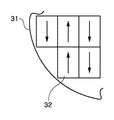
図3において、ウエハ31は露光対象となるウエハの一部分を示したもので、5ショット分だけ図示されている。図中の矢印は、各ショットの露光方向を示している。例えばショット32は、ウエハの外側から内側に向かって露光が行われる。ショット32のようにウエハの外縁部にあり、かつウエハの外側から露光が行われるショットでは、液浸領域がウエハの外側から移動して、露光が行われることになる。これを図4において説明する。
Next, the above (1) to (3) will be described in detail.
(1) In FIG. 1, when there is no liquid immersion state 14 (dry state), that is, in the conventional projection exposure apparatus, vibration caused by the movement of the
(2) The immersion type projection exposure apparatus generates an
(3) In FIG. 3, a
図4はウエハステージを上から見たもので、41がウエハで42は図3のショット32に該当するショットである。ショット42を露光するためには、液浸領域43がウエハ41の外側から内側に向かって移動してこなければならない(実際は液浸領域43が不動で、ウエハステージが駆動する)。そこで、ウエハより外側でも液浸状態を形成するために、ウエハ41の外周に接し、かつウエハ41と同じ高さになるような同面板40を具備している。この同面板40の存在により、ショット42のような外縁部の露光が可能である。しかし、同面板40とウエハ41との間は、
・ミクロンオーダーの隙間
・ミクロンオーダーの高さの差(段差)
・親水性あるいは疎水性の差による摩擦力などの違い
が存在するため、液浸領域43が同面板40からウエハ41へと変位する際に、ウエハステージに対して制御特性変動を与えることになる。そこで本実施形態においては、液浸領域43が同面板40上(すなわちウエハ41にとってはドライ状態)から、ウエハ41上(すなわちウエハ41が液浸状態)に変位する際に、ウエハステージの駆動プロファイル、あるいは制御パラメータを切り替えながら駆動することによって、ドライ状態から液浸状態に移る際の制御特性変動を抑えることを可能とした。
FIG. 4 is a top view of the wafer stage. 41 is a wafer and 42 is a shot corresponding to the
・ Micron order gap ・ Micron order height difference (step)
Since there is a difference in frictional force or the like due to a difference in hydrophilicity or hydrophobicity, when the
本実施形態では、液浸領域がウエハの内側から外側に向かうとき、すなわち液浸状態からドライ状態に変位する際も同様に適用可能である。 In the present embodiment, the present invention can be similarly applied when the immersion area is directed from the inside to the outside of the wafer, that is, when the immersion area is displaced from the immersion state to the dry state.
次に、駆動プロファイルの変更方法について述べる。図5はウエハステージ・スキャン時の加速度目標値の一例を示す概略図である。図2のプロファイラ21においては、この加速度目標値を2階積分した位置目標値が生成され出力される。図5は横軸が時間、縦軸が加速度を示す。50は駆動開始時の最大加速度、59は停止時の最大加速度(負値)である。51、53、56、58は加速度の変化率を決定するJerk時間である。52、57は最大加速度を維持する時間である。54はウエハステージが51→52→53を経て最大速度に達してから、所望の位置決め精度すなわちレチクルステージとの同期精度に収束するまでの整定時間である。この整定時間54の後に、露光時間55に入り、露光が行われ、56→57→58を経て駆動が終了する。図5はスキャン時の加速度目標値を示したが、ステップ時は54の整定時間がなくなり、55の露光時間が単なる等速時間に変わったものと考えればよい。
Next, a method for changing the drive profile will be described. FIG. 5 is a schematic diagram showing an example of an acceleration target value at the time of wafer stage scanning. In the
液浸状態においては、液浸液によりウエハステージの収束が悪化してしまう。そこで、整定時間54をドライ状態の時より長くすることで、同期精度の悪化を防ぐことができる。しかし、整定時間54を長くするとスループットの低下につながってしまう。液浸状態において悪化した収束波形には特定の周波数成分f1[Hz]が含まれていることが多い。ウエハステージが発生する力は液浸液に印加されるが、これは加速度に比例するため、51→52→53の加速度波形がf1を含まないように、50、51、52、53を選択する。それによって、整定時間54を長くすることなく、同期精度の悪化を防ぐことが可能となる。
In the immersion state, the convergence of the wafer stage is deteriorated by the immersion liquid. Therefore, the deterioration of the synchronization accuracy can be prevented by setting the
また、液浸ノズル13によって供給される液浸液の流量、流速が増大するとウエハステージへの圧力や脈動による外乱が大きくなり、ステージの位置決め精度を悪化させる。この場合も、図5の加速度目標値を変更することで、位置決め精度の悪化を防ぐことが可能である。
Further, when the flow rate and flow velocity of the immersion liquid supplied by the
液浸状態において、
(i)ウエハやレンズとの接触面積(液浸半径)が大きくなる場合、
(ii)液浸液とウエハまたは液浸液とレンズの接触角が小さくなる場合、
(iii)液浸液の厚さすなわちウエハとレンズとの距離が小さくなる場合
液浸液によるバネ性や粘性は大きくなり、ステージの位置決め精度を悪化させてしまう。そこで、上記接触面積、接触角、液厚に応じて、図5の加速度目標値を変更することで、位置決め精度の悪化を防ぐことが可能である。
In the immersion state,
(I) When the contact area (immersion radius) with the wafer or lens increases,
(Ii) When the contact angle between the immersion liquid and the wafer or the immersion liquid and the lens is small,
(Iii) When the thickness of the immersion liquid, that is, the distance between the wafer and the lens becomes small, the spring property and viscosity due to the immersion liquid become large, and the positioning accuracy of the stage deteriorates. Therefore, it is possible to prevent deterioration in positioning accuracy by changing the acceleration target value in FIG. 5 according to the contact area, contact angle, and liquid thickness.
次に、ステージの制御パラメータの変更方法について述べる。液浸状態においては、液浸液の影響によりウエハステージの周波数特性に変化を生じる。例えばバネ性により10Hz以下のゲインが低くなり、低周波数における追従特性が劣化してしまう。そこで、図2のコントローラ22に含まれているPIDパラメータ
PID(s)=Kp(1+fi/s+s/fd)
ここで、Kp:比例ゲイン,fi:積分周波数,fd:微分周波数,s:ラプラス演算子
のうち比例ゲインKpまたは積分周波数fdを上げることで、低周波数のゲイン低下を補償し、追従特性の悪化を防ぐことが可能となる。また、バネ性による悪影響は、(i)〜(iii)の場合に大きくなるので、接触面積、接触角、液厚に応じて、上記比例ゲインまたは積分周波数を上げるとよい。さらにPIDパラメータの変更は、液浸状態の有無によって駆動毎に切り替えることも有効であるし、ドライ状態から液浸状態またはその逆に変位するショットにおいては駆動中に切り替えることも有効である。
Next, a method for changing the control parameters of the stage will be described. In the immersion state, the frequency characteristics of the wafer stage change due to the influence of the immersion liquid. For example, the gain of 10 Hz or less is lowered due to the spring property, and the follow-up characteristic at a low frequency is deteriorated. Therefore, the PID parameter included in the
PID (s) = Kp (1 + fi / s + s / fd)
Here, Kp: proportional gain, fi: integral frequency, fd: differential frequency, s: Laplace operator's proportional gain Kp or integral frequency fd is increased to compensate for low frequency gain reduction and follow-up characteristics deteriorate. Can be prevented. Further, since the adverse effect due to the spring property is increased in the cases (i) to (iii), it is preferable to increase the proportional gain or the integration frequency according to the contact area, the contact angle, and the liquid thickness. Further, it is effective to change the PID parameter for each driving depending on the presence or absence of the liquid immersion state, and it is also effective to switch during the driving in a shot that is displaced from the dry state to the liquid immersion state or vice versa.
駆動プロファイルや制御パラメータは、ウエハステージのXY座標に応じたテーブルとしてステージ制御部に記憶させておき、切り替えを実施してもよい。さらには、実際の露光結果を元に学習を加え、テーブルの更新を実施するとより大きな効果が得られる。 The drive profile and control parameters may be stored in the stage control unit as a table corresponding to the XY coordinates of the wafer stage and switched. Furthermore, a greater effect can be obtained by performing learning based on the actual exposure result and updating the table.
次に、計測ステージと露光ステージの2つのウエハステージを備えたツインステージ方式の投影露光装置への適用例を示す。図6はツインステージ方式の概念図である。ツインステージの機能については、公知の技術であるため詳細な説明は省略する。 Next, an example of application to a twin stage type projection exposure apparatus provided with two wafer stages of a measurement stage and an exposure stage will be described. FIG. 6 is a conceptual diagram of the twin stage system. Since the function of the twin stage is a known technique, a detailed description thereof will be omitted.
計測ユニット60は計測ステージ61上のウエハ(不図示)のアライメント計測やフォーカス・レベリング計測を行う。64は露光ステージで、搭載された不図示のウエハは照明光ILと投影レンズ62により露光される。その際、液浸ノズル63によって液浸状態65を構成し駆動を行う。このような場合、計測ステージは主にドライ状態であり、露光ステージは液浸状態である時間が多いため、ステージ毎に駆動プロファイルや制御パラメータを変えることによって、液浸状態における位置決め精度の悪化を防ぐことが可能である。もちろん3つ、4つなど2つ以上のウエハステージを備えている投影露光装置に対してもステージ毎に駆動プロファイルや制御パラメータを変更することが可能である。
The
これまで述べた実施の形態は、ステップ&リピート方式の液浸型投影露光装置にも適用が可能である。また、レチクルステージへの適用も可能である。本実施形態では位置制御系を例に挙げたが、速度制御系においても適用可能である。
[デバイス製造方法]
次に、上述した露光装置を利用したデバイス製造方法の実施形態を説明する。
The embodiments described so far can also be applied to a step-and-repeat type immersion projection exposure apparatus. Moreover, application to a reticle stage is also possible. In this embodiment, the position control system is taken as an example, but the present invention can also be applied to a speed control system.
[Device manufacturing method]
Next, an embodiment of a device manufacturing method using the above-described exposure apparatus will be described.
図7は微小デバイス(ICやLSI等の半導体チップ、液晶パネル、CCD、薄膜磁気ヘッド、マイクロマシン等)の製造のフローを示す。ステップS1(回路設計)では半導体デバイスの回路設計を行なう。ステップS2(露光制御データ作成)では設計した回路パターンに基づいて露光装置の露光制御データを作成する。一方、ステップS3(ウエハ製造)ではシリコン等の材料を用いてウエハを製造する。ステップS4(ウエハプロセス)は前工程と呼ばれ、上記用意した露光制御データが入力された露光装置とウエハを用いて、リソグラフィ技術によってウエハ上に実際の回路を形成する。次のステップS5(組み立て)は後工程と呼ばれ、ステップS4によって作製されたウエハを用いて半導体チップ化する工程であり、アッセンブリ工程(ダイシング、ボンディング)、パッケージング工程(チップ封入)等の工程を含む。ステップS6(検査)ではステップS5で作製された半導体デバイスの動作確認テスト、耐久性テスト等の検査を行なう。こうした工程を経て半導体デバイスが完成し、これが出荷(ステップS7)される。 FIG. 7 shows a flow of manufacturing a microdevice (a semiconductor chip such as an IC or LSI, a liquid crystal panel, a CCD, a thin film magnetic head, a micromachine, etc.). In step S1 (circuit design), a semiconductor device circuit is designed. In step S2 (exposure control data creation), exposure control data for the exposure apparatus is created based on the designed circuit pattern. On the other hand, in step S3 (wafer manufacture), a wafer is manufactured using a material such as silicon. Step S4 (wafer process) is called a pre-process, and an actual circuit is formed on the wafer by lithography using the wafer and the exposure apparatus to which the prepared exposure control data is input. The next step S5 (assembly) is called a post-process, and is a process for forming a semiconductor chip using the wafer manufactured in step S4, and is a process such as an assembly process (dicing, bonding), a packaging process (chip encapsulation), or the like. including. In step S6 (inspection), the semiconductor device manufactured in step S5 undergoes inspections such as an operation confirmation test and a durability test. Through these steps, the semiconductor device is completed and shipped (step S7).
図8は上記ウエハプロセスの詳細なフローを示す。ステップS11(酸化)ではウエハの表面を酸化させる。ステップS12(CVD)ではウエハ表面に絶縁膜を形成する。ステップS13(電極形成)ではウエハ上に電極を蒸着によって形成する。ステップS14(イオン打込み)ではウエハにイオンを打ち込む。ステップS15(レジスト処理)ではウエハに感光剤を塗布する。ステップS16(露光)では上記説明した露光装置によって回路パターンをウエハに焼付露光する。ステップS17(現像)では露光したウエハを現像する。ステップ18(エッチング)では現像したレジスト像以外の部分を削り取る。ステップS19(レジスト剥離)ではエッチングが済んで不要となったレジストを取り除く。これらのステップを繰り返し行なうことによって、ウエハ上に多重に回路パターンが形成される。 FIG. 8 shows a detailed flow of the wafer process. In step S11 (oxidation), the wafer surface is oxidized. In step S12 (CVD), an insulating film is formed on the wafer surface. In step S13 (electrode formation), an electrode is formed on the wafer by vapor deposition. In step S14 (ion implantation), ions are implanted into the wafer. In step S15 (resist process), a photosensitive agent is applied to the wafer. In step S16 (exposure), the circuit pattern is printed on the wafer by exposure using the exposure apparatus described above. In step S17 (development), the exposed wafer is developed. In step 18 (etching), portions other than the developed resist image are removed. In step S19 (resist stripping), the resist that has become unnecessary after the etching is removed. By repeating these steps, multiple circuit patterns are formed on the wafer.
1 レチクル
2 レチクルステージ
3 レチクルステージ用レーザー干渉計
4,62 投影レンズ
5,31,41 ウエハ
6,23 ウエハステージ
7 ウエハステージ用レーザー干渉計
8 レチクルステージ定盤
9 ウエハステージ定盤
10 本体構造体
11,25 ステージ制御部
13,63 液浸ノズル
14,65 液浸状態
15 本体用アクティブマウント
16 ステージ用アクティブマウント
20 変更手段
21 プロファイラ
22 コントローラ
24 レーザー干渉計
32,42 ショット
40 同面板
43 液浸領域
60 計測ユニット
61 計測ステージ
64 露光ステージ
DESCRIPTION OF
Claims (12)
前記基板を保持した状態で移動し、前記原版に対して前記基板を位置決めするステージと、
前記ステージの駆動を制御するステージ制御部とを備え、
前記ステージ制御部は、前記基板の表面が前記液体のないドライ状態から前記液浸状態に変位する際の前記液体による前記ステージの制御特性の変動を低減するように、液浸条件に基づいて前記ステージの制御パラメータを変更することを特徴とする液浸露光装置。 An immersion exposure apparatus that exposes an original pattern on a substrate in an immersion state in which a space between a substrate and an optical member facing the substrate is filled with a liquid ,
A stage that moves while holding the substrate and positions the substrate with respect to the original;
A stage control unit for controlling the drive of the stage,
The stage control unit is configured to reduce the fluctuation in the control characteristics of the stage due to the liquid when the surface of the substrate is displaced from the dry state without the liquid to the liquid immersion state based on the liquid immersion condition. An immersion exposure apparatus characterized by changing a control parameter of a stage.
前記基板を保持した状態で移動し、前記原版に対して前記基板を位置決めするステージと、
前記ステージの駆動を制御するステージ制御部とを備え、
前記ステージ制御部は、前記基板の表面が前記液体のないドライ状態から前記液浸状態に変位する際の前記液体による前記ステージの制御特性の変動を低減するように、液浸の有無に基づいて前記ステージの制御パラメータを変更することを特徴とする液浸露光装置。 An immersion exposure apparatus that exposes an original pattern on a substrate in an immersion state in which a space between a substrate and an optical member facing the substrate is filled with a liquid ,
A stage that moves while holding the substrate and positions the substrate with respect to the original;
A stage control unit for controlling the drive of the stage,
The stage control unit is based on the presence or absence of liquid immersion so as to reduce fluctuations in the control characteristics of the stage due to the liquid when the surface of the substrate is displaced from the dry state without the liquid to the liquid immersion state. An immersion exposure apparatus characterized by changing control parameters of the stage.
前記基板と同じ高さになるように前記基板の外周に設けられた同面板と、
前記基板及び前記同面板を保持した状態で移動し、前記原版に対して前記基板を位置決めするステージと、
前記ステージの駆動を制御するステージ制御部とを備え、
前記ステージ制御部は、前記光学部材との間に形成される液浸領域が前記同面板上と前記基板上との間で変位する際の前記液体による前記ステージの制御特性の変動を低減するように、前記ステージの制御パラメータ又は前記ステージの駆動プロファイルを変更することを特徴とする液浸露光装置。 An immersion exposure apparatus that exposes an original pattern on a substrate in an immersion state in which a space between a substrate and an optical member facing the substrate is filled with a liquid ,
A coplanar plate provided on the outer periphery of the substrate so as to have the same height as the substrate;
A stage that moves while holding the substrate and the same surface plate , and positions the substrate with respect to the original plate,
A stage control unit for controlling the drive of the stage,
The stage control unit reduces variation in control characteristics of the stage due to the liquid when a liquid immersion region formed between the optical member and the optical member is displaced between the same surface plate and the substrate. In addition, an immersion exposure apparatus characterized by changing a control parameter of the stage or a drive profile of the stage.
前記基板を保持した状態で移動し、前記原版に対して前記基板を位置決めする露光用ステージと、
前記基板を保持した状態で移動し、前記基板を計測する計測用ステージと、
前記各ステージの駆動を制御するステージ制御部とを備え、
少なくとも前記露光用ステージは前記基板の表面が前記液浸状態のときに駆動され、
前記ステージ制御部は、前記基板の表面が前記液体のないドライ状態から前記液浸状態に変位する際の前記液体による前記ステージの制御特性の変動を低減するように、前記ステージの制御パラメータを前記露光用ステージと前記計測用ステージとの間で変更することを特徴とする液浸露光装置。 An immersion exposure apparatus that exposes an original pattern on a substrate in an immersion state in which a space between a substrate and an optical member facing the substrate is filled with a liquid ,
An exposure stage that moves while holding the substrate and positions the substrate with respect to the original;
A measurement stage that moves while holding the substrate and measures the substrate;
A stage controller for controlling the driving of each stage,
At least the exposure stage is driven when the surface of the substrate is in the liquid immersion state,
The stage control unit sets the control parameters of the stage so as to reduce fluctuations in the control characteristics of the stage due to the liquid when the surface of the substrate is displaced from the dry state without the liquid to the liquid immersion state. An immersion exposure apparatus that changes between an exposure stage and the measurement stage.
前記基板を保持した状態で移動し、前記原版に対して前記基板を位置決めするステージと、
前記ステージの駆動を制御するステージ制御部とを備え、
前記ステージ制御部は、前記液浸状態における前記ステージの収束波形に含まれる特定の周波数成分を前記ステージの加速度波形が含まないように、液浸条件に基づいて前記ステージの駆動プロファイルを変更することを特徴とする液浸露光装置。 An immersion exposure apparatus that exposes an original pattern on a substrate in an immersion state in which a space between a substrate and an optical member facing the substrate is filled with a liquid,
A stage that moves while holding the substrate and positions the substrate with respect to the original;
A stage control unit for controlling the drive of the stage,
The stage control unit changes the drive profile of the stage based on the immersion condition so that the acceleration waveform of the stage does not include a specific frequency component included in the convergence waveform of the stage in the immersion state. An immersion exposure apparatus .
前記基板を保持した状態で移動し、前記原版に対して前記基板を位置決めするステージと、
前記ステージの駆動を制御するステージ制御部とを備え、
前記ステージ制御部は、前記液浸状態における前記ステージの収束波形に含まれる特定の周波数成分を前記ステージの加速度波形が含まないように、液浸の有無に基づいて前記ステージの駆動プロファイルを変更することを特徴とする液浸露光装置。 An immersion exposure apparatus that exposes an original pattern on a substrate in an immersion state in which a space between a substrate and an optical member facing the substrate is filled with a liquid,
A stage that moves while holding the substrate and positions the substrate with respect to the original;
A stage control unit for controlling the drive of the stage,
The stage controller changes the drive profile of the stage based on the presence or absence of immersion so that the acceleration waveform of the stage does not include a specific frequency component included in the convergence waveform of the stage in the immersion state. An immersion exposure apparatus .
前記基板を保持した状態で移動し、前記原版に対して前記基板を位置決めする露光用ステージと、
前記基板を保持した状態で移動し、前記基板を計測する計測用ステージと、
前記各ステージの駆動を制御するステージ制御部とを備え、
少なくとも前記露光用ステージは前記基板の表面が前記液浸状態のときに駆動され、
前記ステージ制御部は、前記液浸状態における前記ステージの収束波形に含まれる特定の周波数成分を前記ステージの加速度波形が含まないように、前記ステージの駆動プロファイルを前記露光用ステージと前記計測用ステージとの間で変更することを特徴とする液浸露光装置。 An immersion exposure apparatus that exposes an original pattern on a substrate in an immersion state in which a space between a substrate and an optical member facing the substrate is filled with a liquid,
An exposure stage that moves while holding the substrate and positions the substrate with respect to the original;
A measurement stage that moves while holding the substrate and measures the substrate;
A stage controller for controlling the driving of each stage,
At least the exposure stage is driven when the surface of the substrate is in the liquid immersion state,
The stage control unit sets the drive profile of the stage to the exposure stage and the measurement stage so that the acceleration waveform of the stage does not include a specific frequency component included in the convergence waveform of the stage in the liquid immersion state. An immersion exposure apparatus characterized by being changed between
Priority Applications (6)
| Application Number | Priority Date | Filing Date | Title |
|---|---|---|---|
| JP2004229812A JP3870207B2 (en) | 2004-08-05 | 2004-08-05 | Immersion exposure apparatus and device manufacturing method |
| KR1020050071173A KR100698934B1 (en) | 2004-08-05 | 2005-08-04 | Liquid immersion exposure apparatus, method of controlling the same, and device manufacturing method |
| EP05017010A EP1624341A3 (en) | 2004-08-05 | 2005-08-04 | Liquid immersion exposure apparatus, method of controlling the same, and device manufacturing method |
| TW094126598A TWI272661B (en) | 2004-08-05 | 2005-08-04 | Liquid immersion exposure apparatus, method of controlling the same, and device manufacturing method |
| US11/196,348 US7692760B2 (en) | 2004-08-05 | 2005-08-04 | Liquid immersion exposure apparatus, method of controlling the same, and device manufacturing method |
| CNA2005100894240A CN1731288A (en) | 2004-08-05 | 2005-08-05 | Liquid immersion exposure apparatus, method of controlling the same, and device manufacturing method |
Applications Claiming Priority (1)
| Application Number | Priority Date | Filing Date | Title |
|---|---|---|---|
| JP2004229812A JP3870207B2 (en) | 2004-08-05 | 2004-08-05 | Immersion exposure apparatus and device manufacturing method |
Publications (2)
| Publication Number | Publication Date |
|---|---|
| JP2006049644A JP2006049644A (en) | 2006-02-16 |
| JP3870207B2 true JP3870207B2 (en) | 2007-01-17 |
Family
ID=35355903
Family Applications (1)
| Application Number | Title | Priority Date | Filing Date |
|---|---|---|---|
| JP2004229812A Expired - Fee Related JP3870207B2 (en) | 2004-08-05 | 2004-08-05 | Immersion exposure apparatus and device manufacturing method |
Country Status (6)
| Country | Link |
|---|---|
| US (1) | US7692760B2 (en) |
| EP (1) | EP1624341A3 (en) |
| JP (1) | JP3870207B2 (en) |
| KR (1) | KR100698934B1 (en) |
| CN (1) | CN1731288A (en) |
| TW (1) | TWI272661B (en) |
Families Citing this family (21)
| Publication number | Priority date | Publication date | Assignee | Title |
|---|---|---|---|---|
| JP2005536775A (en) * | 2002-08-23 | 2005-12-02 | 株式会社ニコン | Projection optical system, photolithography method and exposure apparatus, and method using exposure apparatus |
| KR101516142B1 (en) | 2003-05-06 | 2015-05-04 | 가부시키가이샤 니콘 | Projection optical system, and exposure apparatus and exposure method |
| US7348575B2 (en) | 2003-05-06 | 2008-03-25 | Nikon Corporation | Projection optical system, exposure apparatus, and exposure method |
| US20070058146A1 (en) * | 2004-02-04 | 2007-03-15 | Nikon Corporation | Exposure apparatus, exposure method, position control method, and method for producing device |
| KR20070115859A (en) * | 2005-03-18 | 2007-12-06 | 가부시키가이샤 니콘 | Exposure method, exposure apparatus, device manufacturing method and exposure apparatus evaluating method |
| JP4923480B2 (en) * | 2005-08-23 | 2012-04-25 | 株式会社ニコン | Exposure apparatus, device manufacturing method, and measurement member |
| JP2007194484A (en) * | 2006-01-20 | 2007-08-02 | Toshiba Corp | Liquid immersion exposure method |
| US8134681B2 (en) * | 2006-02-17 | 2012-03-13 | Nikon Corporation | Adjustment method, substrate processing method, substrate processing apparatus, exposure apparatus, inspection apparatus, measurement and/or inspection system, processing apparatus, computer system, program and information recording medium |
| TWI610149B (en) * | 2006-08-31 | 2018-01-01 | Nikon Corp | Mobile body drive system, moving body driving method, pattern forming apparatus and method, exposure apparatus and method, component manufacturing method, and determination method |
| JP2008124194A (en) * | 2006-11-10 | 2008-05-29 | Canon Inc | Liquid-immersion exposure method and liquid-immersion exposure apparatus |
| JP5006122B2 (en) | 2007-06-29 | 2012-08-22 | 株式会社Sokudo | Substrate processing equipment |
| JP5160204B2 (en) * | 2007-11-30 | 2013-03-13 | 株式会社Sokudo | Substrate processing equipment |
| JP5128918B2 (en) | 2007-11-30 | 2013-01-23 | 株式会社Sokudo | Substrate processing equipment |
| JP5318403B2 (en) | 2007-11-30 | 2013-10-16 | 株式会社Sokudo | Substrate processing equipment |
| US8953141B2 (en) * | 2007-12-21 | 2015-02-10 | Asml Netherlands B.V. | Immersion lithographic apparatus and device manufacturing method with asymmetric acceleration profile of substrate table to maintain meniscus of immersion liquid |
| JP5179170B2 (en) * | 2007-12-28 | 2013-04-10 | 株式会社Sokudo | Substrate processing equipment |
| JP5001828B2 (en) * | 2007-12-28 | 2012-08-15 | 株式会社Sokudo | Substrate processing equipment |
| JP2009182110A (en) * | 2008-01-30 | 2009-08-13 | Nikon Corp | Exposure system, exposure method and device manufacturing method |
| JP2013004942A (en) * | 2011-06-22 | 2013-01-07 | Renesas Electronics Corp | Semiconductor device manufacturing method |
| TWI501334B (en) * | 2013-06-04 | 2015-09-21 | Yayatech Co Ltd | Liquid immersion apparatus and immersion method and wafer scribing lines inspection machine with liquid immersion apparatus |
| TWI564680B (en) * | 2016-03-23 | 2017-01-01 | The control method of the scanning light source of the exposure machine and the computer program product |
Family Cites Families (28)
| Publication number | Priority date | Publication date | Assignee | Title |
|---|---|---|---|---|
| EP0360206A3 (en) | 1988-09-21 | 1990-12-19 | Hitachi, Ltd. | Self-tuning controller apparatus and process control system |
| JPH06124873A (en) | 1992-10-09 | 1994-05-06 | Canon Inc | Liquid-soaking type projection exposure apparatus |
| JP2899196B2 (en) | 1993-06-30 | 1999-06-02 | キヤノン株式会社 | Scan type exposure equipment |
| JPH0927447A (en) | 1995-07-11 | 1997-01-28 | Nikon Corp | Stage drive controller |
| JP3747566B2 (en) | 1997-04-23 | 2006-02-22 | 株式会社ニコン | Immersion exposure equipment |
| AU2747999A (en) | 1998-03-26 | 1999-10-18 | Nikon Corporation | Projection exposure method and system |
| JP2002025886A (en) | 2000-07-03 | 2002-01-25 | Canon Inc | Step-and-scan type projection aligner, maintenance method therefor, and semiconductor device manufacturing method and semiconductor manufacturing plant using the aligner |
| JP2002184687A (en) | 2000-10-02 | 2002-06-28 | Canon Inc | Aligner |
| JP3559766B2 (en) | 2001-02-21 | 2004-09-02 | キヤノン株式会社 | Scanning exposure apparatus, scanning exposure method, and device manufacturing method |
| JP2003133216A (en) | 2001-10-26 | 2003-05-09 | Canon Inc | Exposure method and exposure apparatus |
| JP4109891B2 (en) | 2002-04-19 | 2008-07-02 | キヤノン株式会社 | Active vibration control apparatus, exposure apparatus, and device manufacturing method |
| DE60335595D1 (en) * | 2002-11-12 | 2011-02-17 | Asml Netherlands Bv | Immersion lithographic apparatus and method of making a device |
| JP4323783B2 (en) | 2002-11-29 | 2009-09-02 | キヤノン株式会社 | Exposure apparatus and method, and original plate manufacturing method |
| KR20050085235A (en) * | 2002-12-10 | 2005-08-29 | 가부시키가이샤 니콘 | Exposure system and device producing method |
| CN1723541B (en) * | 2002-12-10 | 2010-06-02 | 株式会社尼康 | Exposure apparatus and method for producing device |
| KR101101737B1 (en) * | 2002-12-10 | 2012-01-05 | 가부시키가이샤 니콘 | Exposure apparatus, exposure method and method for manufacturing device |
| JP4595320B2 (en) | 2002-12-10 | 2010-12-08 | 株式会社ニコン | Exposure apparatus and device manufacturing method |
| TWI295414B (en) * | 2003-05-13 | 2008-04-01 | Asml Netherlands Bv | Lithographic apparatus and device manufacturing method |
| TW201515064A (en) * | 2003-05-23 | 2015-04-16 | 尼康股份有限公司 | Exposure device, exposure method, and device manufacturing method |
| US6809794B1 (en) * | 2003-06-27 | 2004-10-26 | Asml Holding N.V. | Immersion photolithography system and method using inverted wafer-projection optics interface |
| EP1494074A1 (en) | 2003-06-30 | 2005-01-05 | ASML Netherlands B.V. | Lithographic apparatus and device manufacturing method |
| US7738074B2 (en) * | 2003-07-16 | 2010-06-15 | Asml Netherlands B.V. | Lithographic apparatus and device manufacturing method |
| CN102043350B (en) | 2003-07-28 | 2014-01-29 | 株式会社尼康 | Exposure apparatus, device manufacturing method, and control method of exposure apparatus |
| KR101915921B1 (en) | 2003-08-21 | 2019-01-07 | 가부시키가이샤 니콘 | Exposure apparatus, exposure method, and device producing method |
| JP2005079480A (en) | 2003-09-02 | 2005-03-24 | Nikon Corp | Aligner and method for manufacturing device |
| JP2005083800A (en) * | 2003-09-05 | 2005-03-31 | Hitachi Ltd | Flaw inspection method and flaw inspection device |
| JP4479911B2 (en) | 2004-02-18 | 2010-06-09 | 株式会社ニコン | Driving method, exposure method, exposure apparatus, and device manufacturing method |
| US7295283B2 (en) | 2004-04-02 | 2007-11-13 | Asml Netherlands B.V. | Lithographic apparatus and device manufacturing method |
-
2004
- 2004-08-05 JP JP2004229812A patent/JP3870207B2/en not_active Expired - Fee Related
-
2005
- 2005-08-04 TW TW094126598A patent/TWI272661B/en not_active IP Right Cessation
- 2005-08-04 EP EP05017010A patent/EP1624341A3/en not_active Withdrawn
- 2005-08-04 KR KR1020050071173A patent/KR100698934B1/en not_active IP Right Cessation
- 2005-08-04 US US11/196,348 patent/US7692760B2/en not_active Expired - Fee Related
- 2005-08-05 CN CNA2005100894240A patent/CN1731288A/en active Pending
Also Published As
| Publication number | Publication date |
|---|---|
| JP2006049644A (en) | 2006-02-16 |
| KR100698934B1 (en) | 2007-03-26 |
| CN1731288A (en) | 2006-02-08 |
| TWI272661B (en) | 2007-02-01 |
| EP1624341A2 (en) | 2006-02-08 |
| TW200618060A (en) | 2006-06-01 |
| KR20060049270A (en) | 2006-05-18 |
| US20060028630A1 (en) | 2006-02-09 |
| US7692760B2 (en) | 2010-04-06 |
| EP1624341A3 (en) | 2006-11-22 |
Similar Documents
| Publication | Publication Date | Title |
|---|---|---|
| JP3870207B2 (en) | Immersion exposure apparatus and device manufacturing method | |
| KR100253054B1 (en) | Aligner and exposure method using the same | |
| US20100149513A1 (en) | Fluid pressure compensation for immersion litography lens | |
| US6699630B2 (en) | Method and apparatus for exposure, and device manufacturing method | |
| US20020080339A1 (en) | Stage apparatus, vibration control method and exposure apparatus | |
| JP5516740B2 (en) | MOBILE BODY DRIVING METHOD, MOBILE BODY DEVICE, EXPOSURE METHOD, EXPOSURE APPARATUS, AND DEVICE MANUFACTURING METHOD | |
| JP2009105414A (en) | Exposure method, and device manufacturing method | |
| JP5404745B2 (en) | Positioning system, lithographic apparatus and position control method | |
| KR100790634B1 (en) | Immersion exposure apparatus, immersion exposure method, and device manufacturing method | |
| JP2000021702A (en) | Aligner and manufacture of devices | |
| US6641981B1 (en) | Exposure method, exposure apparatus, and device manufacturing method | |
| JP4479911B2 (en) | Driving method, exposure method, exposure apparatus, and device manufacturing method | |
| JP2008244386A (en) | Aberration measuring method, exposure system, and method of manufacturing device | |
| JP2009088018A (en) | Method and apparatus for controlling stage, method and apparatus for exposure, and device manufacturing method | |
| JP2003315479A (en) | Stage apparatus, its control method, and exposure apparatus | |
| JP6610719B2 (en) | Drive system and drive method, exposure apparatus and exposure method, and device manufacturing method | |
| JP2005308145A (en) | Vibration-isolating device and exposure device | |
| JP2008153546A (en) | Moving object mechanism | |
| JP2005331009A (en) | Vibration control device and exposing device | |
| JP2005063167A (en) | Positioning apparatus, its control method and exposure apparatus | |
| JP6536777B2 (en) | Control system and control method, exposure apparatus and exposure method, and device manufacturing method | |
| JPH10106933A (en) | Device and method for scanning type exposure | |
| JP2001291662A (en) | Exposure method and aligner and method of manufacturing device | |
| KR20220014293A (en) | Exposing apparatus and method for manufacturing article | |
| JPH1197339A (en) | Aligner |
Legal Events
| Date | Code | Title | Description |
|---|---|---|---|
| A977 | Report on retrieval |
Free format text: JAPANESE INTERMEDIATE CODE: A971007 Effective date: 20060629 |
|
| A131 | Notification of reasons for refusal |
Free format text: JAPANESE INTERMEDIATE CODE: A131 Effective date: 20060707 |
|
| A521 | Written amendment |
Free format text: JAPANESE INTERMEDIATE CODE: A523 Effective date: 20060905 |
|
| TRDD | Decision of grant or rejection written | ||
| A01 | Written decision to grant a patent or to grant a registration (utility model) |
Free format text: JAPANESE INTERMEDIATE CODE: A01 Effective date: 20061002 |
|
| A61 | First payment of annual fees (during grant procedure) |
Free format text: JAPANESE INTERMEDIATE CODE: A61 Effective date: 20061016 |
|
| R150 | Certificate of patent or registration of utility model |
Free format text: JAPANESE INTERMEDIATE CODE: R150 |
|
| FPAY | Renewal fee payment (event date is renewal date of database) |
Free format text: PAYMENT UNTIL: 20091020 Year of fee payment: 3 |
|
| FPAY | Renewal fee payment (event date is renewal date of database) |
Free format text: PAYMENT UNTIL: 20101020 Year of fee payment: 4 |
|
| FPAY | Renewal fee payment (event date is renewal date of database) |
Free format text: PAYMENT UNTIL: 20101020 Year of fee payment: 4 |
|
| FPAY | Renewal fee payment (event date is renewal date of database) |
Free format text: PAYMENT UNTIL: 20111020 Year of fee payment: 5 |
|
| FPAY | Renewal fee payment (event date is renewal date of database) |
Free format text: PAYMENT UNTIL: 20111020 Year of fee payment: 5 |
|
| FPAY | Renewal fee payment (event date is renewal date of database) |
Free format text: PAYMENT UNTIL: 20121020 Year of fee payment: 6 |
|
| FPAY | Renewal fee payment (event date is renewal date of database) |
Free format text: PAYMENT UNTIL: 20131020 Year of fee payment: 7 |
|
| LAPS | Cancellation because of no payment of annual fees |