JP3856877B2 - Game device - Google Patents
Game device Download PDFInfo
- Publication number
- JP3856877B2 JP3856877B2 JP26360996A JP26360996A JP3856877B2 JP 3856877 B2 JP3856877 B2 JP 3856877B2 JP 26360996 A JP26360996 A JP 26360996A JP 26360996 A JP26360996 A JP 26360996A JP 3856877 B2 JP3856877 B2 JP 3856877B2
- Authority
- JP
- Japan
- Prior art keywords
- sphere
- rotation
- speed
- game apparatus
- spheres
- Prior art date
- Legal status (The legal status is an assumption and is not a legal conclusion. Google has not performed a legal analysis and makes no representation as to the accuracy of the status listed.)
- Expired - Fee Related
Links
Images


Description
【0001】
【発明の属する技術分野】
本発明は、ゲーム装置、特にゲームセンターなどに設置される業務用ゲーム装置に関する。
【0002】
【従来の技術】
従来の玉を飛ばしてバスケット等に入れる玉入れゲーム機として、例えば、特開平7−275498号に記載のものがある。このゲーム機は、回転支持台に支持されたソレノイドにより玉を飛ばす機構と、ハンドルの回転を回転支持台の回転に伝達する機構と、釦の押下によりソレノイドを動作させる機構を有する。
【0003】
【発明が解決しようとする課題】
この様な従来のゲーム装置は、玉を飛ばすための遊戯者の操作が、発射釦の押下のみであるため、遊戯操作が極めて単純であり、遊戯性が低いものとなっている。また、玉を飛ばすための機構が、ソレノイドとプランジャを用いたもので、発射釦の押下により1個ずつ玉を飛ばすため、視覚効果や遊戯性が低いものである。また、回転ハンドルと回転支持台を、リンクを用いた機械的構成で接続しているため、回転支持台の回転動作は回転ハンドルの操作に比例した動作となり、柔軟な回転動作を行わせることが困難である。
本発明は、前記のようなことから、玉入れゲーム装置の玉を飛ばすための遊戯操作の遊戯性の向上を目的とする。
【0004】
【課題を解決するための手段】
本発明の手段は、遊戯者の操作により球体を目標物に向かって飛ばすことを含むゲーム装置であって、遊戯者により継続して操作されることにより回転部材を回転させる回転操作手段と、前記回転部材の回転速度を検出する速度検出手段と、前記ゲーム装置に収容された多数の球体の中の複数個を連続的に飛ばす球体発射手段と、前記速度検出手段の検出回転速度に応じて前記球体発射手段の発射動作速度を制御する第1の制御手段と、を備えている。前記回転操作手段が、前記回転部材を連動回転させるように設けた回転ハンドルであり、前記速度検出手段は、前記回転部材の周囲に断続して設けられた被検出部と、その被検出部を検知して回転速度信号を第1制御手段へ出力する被接触センサーとからなる。前記ゲーム装置内部に設けた盤面が、球体を集合させる傾斜面を具備し、前記球体発射手段は、前記傾斜面によって球体が集合する集合部に接近して設けられ駆動源により回転する回転軸と、該回転軸に取り付けられ回転により前記集合部の球体の複数個を同時に飛ばすように設けた少なくとも一つの羽根と、を具備する。
【0005】
遊戯者が回転操作手段を操作すると、回転部材が回転してその回転速度が速度検出手段によって検出され、その検出回転速度に応じて第1の制御手段が球体発射手段の発射動作速度を制御する。従って、発射される球体の速度は、回転操作手段の操作を加減することによって変更される。そして、遊戯者により継続して操作される回転操作手段を用いたので、従来の単純な押釦を押して放す操作に比べ、継続性を要求される操作となり、より遊戯性の高いゲーム装置となる。更に、回転操作手段による回転部材の回転速度に応じて発射手段の発射動作速度を制御する第1の制御手段を設けたので、回転操作手段による回転部材の回転速度に対する球体発射手段の発射動作速度を、単純に比例しない関係としたり、上限や下限を設けた関係とすることができる。更に、回転操作手段を、回転ハンドルとしたので、従来の釦を押し下げる操作手段に比べ、より自然な動作で継続した操作を行うことが可能となる。また、速度検出手段が、回転ハンドルに連動回転する回転部材の周囲に断続して設けられた被検出部を非接触センサーで検出する構成としたので、簡単な構成で従来にない回転操作速度検出手段を実現できると共に、故障や誤動作を少なくできる。その上、ゲーム装置内に適当な数量の球体を収容しておくと、球体は傾斜面を下降して集合するので、その集合部の球体を発射手段により飛ばしても再度集合部に戻ってくるから、球体発射手段が連続的に動作していても常に集合部に球体が存在する。従って、球体発射手段は複数の球体を同時に発射でき、しかも連続的に発射できるから、1個ずつ発射する従来のゲーム装置に比べ、視覚的に華やかであり、遊戯性が高いものとなる。
【0010】
前記回転操作手段が、遊戯者の操作により左右に揺動操作可能に設けられ、別に、前記回転操作手段の揺動を検知して信号を発する揺動検知手段と、前記球体発射手段を左右に揺動させる移動手段と、前記揺動検知手段からの信号に応じて前記移動手段に球体発射手段を左右に移動させる第2の制御手段とを設けた構成とするのがよい。
【0011】
このように構成することによって、遊戯者は回転操作手段を回転操作しながら同時に移動操作可能である。従って、球体が飛ばされる方向を見ながら移動操作することにより、球体の飛ぶ方向を変えることができる。また、操作手段と発射手段とのあいだにリンク機構のような機械的機構を用いないで、揺動幅や揺動速度などを自由に設定可能となり、より遊戯性の高いゲーム装置とすることが可能となる。また、操作手段と発射手段とのあいだにリンク機構のような機械的機構を用いない構成は、遊戯待機中などに、操作手段の揺動により発射手段が揺動することを容易に禁止でき、球体発射手段の過剰動作による故障を防止できる。
【0012】
前記目標物が、前記ゲーム装置内部を移動可能なように構成され、上側から下側へ前記球体の通過できる通過部を有するものであり、その通過部を通過した球体の数を計数して表示する表示部を別に設けた構成とするのがよい。
【0013】
このような構成では、限られた時間内に、移動する目標物に球体をどれだけ多く投入できるかという遊戯性をもたせることが可能となる。
【0014】
前記目標物、回転操作手段、回転速度検出手段、球体発射手段を備えた2組のゲーム装置を、互いに球体発射方向が略向き合うように対向させて設け、夫々の前記目標物を向き合った相手側の球体発射手段に設けてその球体発射手段の前記移動に伴って移動するように構成するのがよい。
【0015】
この構成では、二人の遊戯者が同時に遊戯し、夫々に向き合った球体発射手段に目標物を設けてあり、夫々相手の目標物を自分の球体発射手段を移動させることによって移動させることができ、相手の投入数を少なくしながら自分の投入数を多くするという、対戦形式の遊戯性を有するものとなる。
【0016】
【発明の実施の形態】
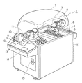
本発明の1実施の形態を図1〜図5を用いて説明する。このゲーム装置1は、2人の遊戯者が対戦できるように構成したもので、図1に外観を示すように、同様な2つの装置を向かい合わせに設けてあり、遊戯者が夫々の回転ハンドル10を回転させてボール4を発射することにより、相手側の人形7の背後に設けたバスケット8に入れるボールの数を得点として競うゲーム装置である。
【0017】
ゲーム装置1は、図1に示すように、略直方体の基台2の上方を透明なアクリル樹脂製の丸みを帯びたドーム3で覆われており、基台2の上部のドーム3内には、球体4を集合させるための傾斜を有する遊戯盤面5が設けられている。この遊戯盤面5の傾斜は、双方の同様な装置の対向する中間部を境に両側へ下降傾斜し、両端部で上昇傾斜しており、遊戯者から見て夫々の手前側へ球体であるボール4が集合するようになっている。このボールが集合する位置に夫々球体発射手段6を設けてある。球体発射手段6の上部には球体を発射する子供を模した人形7が設けられ、人形の背後に球体を受け入れる相手側の目標物としてのバスケット8が設けられている。バスケット8は、上から入ったボール4が下方へ通り抜けて遊戯盤面5上に戻るように筒状に形成され、その内部にはボール4が通過したことを検知する、例えば接触部材とリミットスイッチからなるセンサー16が設けられている。
【0018】
基台2の対向する側面の上部には、夫々遊戯者が操作を行う操作盤9が設けられている。夫々の操作盤9には、中央部に遊戯者が操作する回転操作手段としての回転ハンドル10が盤面から起立した支柱41に設けられている。ハンドル10は両側に突出した1対のレバー11を有しており、遊戯者が両手でレバー11を把持して回転ハンドル10を回転させることができ、後述するようにこの回転に基いて結果的に球体発射手段6が作動し、ボール4を発射する。また、回転ハンドル10は、支柱41の下端部が軸32に支持されていてその軸32を中心に左右に傾動するようになっている。この傾動に基いて、後述するように結果的に球体発射手段6が左右に移動する。
【0019】
操作盤9の左側には、音声を発するスピーカ開口部12が、中央手前側には得点を表示する1対の表示部13、14が設けられている。表示部13は対戦相手の得点を、表示部14は自分の得点をそれぞれ表示する。この得点はバスケット8を通過したボールの数を計数したものである。また、基台2の操作盤9の上面には、遊戯方法や料金を示す案内が表示してある。また、一方の操作盤9の下部には、コイン投入口15が設けられている。
【0020】
回転操作手段は、図2、図3に示すように、前記回転ハンドル10が軸19を支柱41に回転可能に軸受支持され、その軸19に回転部材としての円板20を固定され、円板20が回転ハンドル10の回転とともに回転する。この回転部材である円板20の実質的な回転速度を検出するために、円板20の外周に被検出部として多数の切り欠き部40を設けられ、これを検知するフォトセンサ21が支柱41上端のカバー42の内面に固定されている。このような構成により、回転ハンドル10の回転方向にかかわらず円板20の回転速度を検出することができる。この検知信号は回転速度に対応する電気的なパルス信号であり、フォトセンサ21と切り欠き部40を有する円板20とは速度検出手段である。検知信号は、図示していない電気的な制御部からなる第1の制御手段に送られる。
【0021】
前記回転操作手段は、図2、図4に示すように、遊戯者によって左右に揺動可能に回転ハンドル10の支柱41の下端部を軸32によって支持されている。そして、この揺動の方向、すなわち右方か左方かを検出する揺動検知手段を設けてある。揺動検知手段は軽トルクスイッチ30、31であり、図4に示すように、支柱41の下端の軸32を挟む両側下方位置には突出縁43を設けてあり、この突出縁43に対応して軽トルクスイッチ30、31を基台側に固定した構成である。これは回転操作手段の揺動の方向と反対側の軽トルクスイッチが動作してその揺動を検知するようになっている。この揺動の検知信号は図示していない電気的制御部である第2の制御手段へ送られる。
【0022】
球体発射手段6は、図1、図2、図5に示すように、前面に複数の、例えば5箇のスリットを有するカバー25を設け、このカバー25内に設けてある。カバー25は、前記球体集合部を構成する斜面の下流に位置させてあり、常にボール4が前側に移動してきて貯留される。カバー25内には、2枚の羽根33を外周の180度異なる位置から夫々突出させた羽根付きプーリ22を設けてあり、その羽根33は前記スリットを通過できる5個の突起部を先端側に有する櫛状に形成されている。羽根付きプーリ22は無端ベルト23を介してモータ24により回転駆動され、回転により羽根33の突起部がスリットから出た位置を通り、この時貯留されているボール4が斜め上方の前方へ弾き飛ばされる。モータ24は、前記回転ハンドル10の回転により回転する円板20の回転速度に基いて前記第1の制御部で決められる回転速度で回転駆動される。前記羽根付きプーリ22の羽根33は、例えばボール4の直径が40mmで、羽根の幅が110mmとされ、羽根33がスリットを1度通過すると、少なくとも2個以上のボールが同時に発射される。この前記球体発射手段6は、移動手段によって左右に移動するようになっている。
【0023】
その球体発射手段6を移動させる構成は、図2、図5に示すように、球体発射手段6を左右に移動可能に支持しているレール状のスライダーガイド26、カバー25の後部に固定され後方へ伸延しているスライドアーム27、このスライドアーム27に先端のローラが係合して定位置を中心に180度の範囲を往復回動する揺動アーム28、この揺動アーム28を駆動するモータ29等で構成されている。モータ29が駆動手段であり、前記回転ハンドル10の揺動を検知する軽トルクスイッチ30、31の信号に基いて第2の制御部により制御される。すなわち、ハンドル10が右へ揺動していると検知した場合には、モータ29が揺動アーム28を先端が右へ回動するように駆動し、これによってスライドアーム27が右へ移動せしめられ、球体発射手段6が右へ移動する。ハンドル10が左へ揺動していると検知した場合は、同様にして球体発射手段6が左へ移動する。ハンドル10の揺動が戻されて中立状態になったときは球体発射手段6の左右移動が停止する。なお、球体発射手段6の左右移動により、元の位置にあった部分の空所は球体発射手段6に設けあるカバーで覆われるようになっており、支障はない。
【0024】
なお、スピーカ開口部12からの音声は、例えば、待機中にBGMが流れ、コイン(100円)の投入によりBGMが停止し、クレジット音が発生し、さらにコイン(200円)が投入されると、操作説明、BGMが開始され、操作説明、BGM終了後に50秒程度のゲーム時間があり、その間始めの40秒間プレイ中のBGM1、次の10秒間に緊迫感を煽るBGM2が流れ、終了時点で終了音(笛の音)が出され、最後に夫々の合計得点と勝者がアナウンスされる、ようになっている。
【0025】
このゲーム装置1は、次のように使用される。コイン(通常200円)の投入により、音声による操作説明が行われてから、ゲーム開始状態となる。ゲーム開始と同時に、回転ハンドル10の回転操作により球体発射手段6が動作し、ボール4が発射される。回転ハンドル10の回転速度の変化によって羽根付きプーリ22の回転速度が変化するから、ボール4の発射速度が変化し、バスケット8の位置にボール4が丁度到達するように回転操作速度を工夫する。発射したボール4が相手側のバスケット8にできるだけ多く入るように球体発射手段6をハンドル10の揺動操作により左右に移動させて狙いを付けると共に相手側から発射されるボール4が自分の側のバスケット8に入らないように左右移動を工夫する。バスケット8に入ったボール4の数は、入る度毎に表示部13、14に合計して表示される。ゲーム終了後には、夫々の合計得点と勝者がアナウンスされる。
【0026】
このゲーム装置1は、回転ハンドル10の回転が回転速度を検出し、一旦電気信号に変換し、その信号に応じて適当な回転速度で球体発射手段6の羽根付きプーリ22を回転させる構成であるから、機械的な連結構造に比べて、羽根付きプーリ22の回転速度を任意に制限できる。例えば、回転ハンドル10が無闇に速く回転操作されても、モータ24の回転に上限と下限を設けて、破損を防止したり、また、ボールが前方へ飛ばないような状態を回避させて、興味の低下を防止することが可能である。また、球体発射手段6を左右に移動させる構成も回転ハンドル10の揺動と軽トルクスイッチ30、31とにより検知してモータ29を駆動して行うから、間接駆動であり、機械的に直接駆動する構成に比べて揺動する部分である球体発射手段6が損傷を受けにくい。
【0027】
前記実施の形態において2人が対戦する構成のものとして説明したが、場合によっては、1人で遊戯できる構成にすることが可能である。すなわち、例えば前記実施の形態において、一方の操作盤9を1人が操作し、相手側操作盤を人が操作するのでなく、球体の発射や揺動が適当なプログラムにしたがって自動的に動作するように構成すればよい。
また別に、ゲーム装置を2人が対戦する形式としないで、バスケットを自動的に揺動させ、そのバスケットに向けて前記実施の形態における一方の遊戯者が操作する部分を設けて、所定遊戯時間の得点を表示し、複数人が順番にゲームを行って得点を競うようにしてもよい。
【0028】
【発明の効果】
請求項1に記載の発明は、遊戯者が操作部を継続して回転操作することから、単純な押釦操作よりも遊戯性が高いものとなる効果を奏する。また、球体発射手段の球体発射動作速度が、回転部材の回転速度と第1の制御手段とにより適切に制御できるので、遊戯性を損なわないようにできる効果を奏する。
また、請求項1に記載の発明は、継続した操作を自然に行うことができ、故障や誤動作を防止できる効果を奏する。
さらに、請求項1に記載の発明は、1個ずつ発射する従来のゲーム装置に比べ、視覚的効果にすれ、遊戯性がより高いという効果を奏する。
請求項2に記載の発明は、回転操作手段により球体の発射速度と、球体の発射方向とを操作できるから、より遊戯性の高いゲーム装置とすることができ、発射手段の移動幅や移動速度を回転操作手段の揺動と第2の制御手段とにより適切に制御できるので、より遊戯性の高いものとなる効果を奏し、待機中に球体発射手段を操作できないようにすることが可能であるから、球体発射手段が故障しにくい効果を奏する。
請求項3に記載の発明は、移動する目標物に球体を投入するので、ゲーム性が向上する効果を奏する。
請求項4に記載の発明は、一人対一人の対戦形式の遊戯性の高いゲーム装置とすることができる効果を奏する。
【図面の簡単な説明】
【図1】本発明の1実施の形態の外観を示す斜視図である。
【図2】同実施の形態の片側の主要部の構成を示す縦断側面図である。
【図3】同実施の形態の回転操作手段の部分破断拡大平面図である。
【図4】同実施の形態の回転操作手段の揺動を検知する検知手段の正面図である。
【図5】図2に対応する概略平面図である。
【符号の説明】
1 ゲーム装置
2 基台
3 ドーム
4 ボール(球体)
5 遊戯盤面
6 球体発射手段
7 人形
8 バスケット(目標物)
9 操作盤
10 回転ハンドル(回転操作手段)
11 レバー
12 スピーカ開口部
13 表示部
14 表示部
16 センサー
19 軸
20 円板(回転部材)(速度検出手段)
21 フォトセンサ(速度検出手段)
22 羽根付きプーリ
23 無端ベルト
24 モータ
25 カバー
26 スライダーガイド
27 スライドアーム
28 揺動アーム
29 モータ(駆動手段)
30 軽トルクスイッチ(揺動検知手段)
32 軸
33 羽根
40 切り欠き
41 支柱
42 カバー
43 突出縁[0001]
BACKGROUND OF THE INVENTION
The present invention relates to a game device, and more particularly to an arcade game device installed in a game center or the like.
[0002]
[Prior art]
For example, JP-A-7-275498 discloses a conventional game machine for throwing balls into a basket or the like. This game machine has a mechanism for flying a ball by a solenoid supported by a rotation support base, a mechanism for transmitting the rotation of the handle to the rotation of the rotation support base, and a mechanism for operating the solenoid by pressing a button.
[0003]
[Problems to be solved by the invention]
In such a conventional game device, since the player's operation to fly the ball is only pressing the launch button, the game operation is extremely simple and the playability is low. Further, the mechanism for flying the ball uses a solenoid and a plunger, and the ball is blown one by one when the firing button is pressed, so that the visual effect and playability are low. In addition, since the rotation handle and the rotation support base are connected with a mechanical configuration using a link, the rotation operation of the rotation support base is an operation proportional to the operation of the rotation handle, and a flexible rotation operation can be performed. Have difficulty.
In view of the above, an object of the present invention is to improve the playability of a play operation for skipping a ball of a ball game device.
[0004]
[Means for Solving the Problems]
The means of the present invention is a game apparatus including flying a sphere toward a target by a player's operation, the rotation operation means for rotating the rotating member by being continuously operated by the player, Speed detecting means for detecting the rotational speed of the rotating member, sphere launching means for continuously flying a plurality of spheres accommodated in the game apparatus, and the speed detecting means according to the detected rotational speed of the speed detecting means. First control means for controlling the firing operation speed of the sphere launching means . The rotation operation means is a rotary handle provided so as to rotate the rotary member in an interlocked manner, and the speed detection means includes a detected part provided intermittently around the rotary member, and a detected part. And a contacted sensor that detects and outputs a rotation speed signal to the first control means. A board surface provided inside the game apparatus has an inclined surface for collecting spheres, and the sphere launching means is provided close to a collecting portion where the spheres are assembled by the inclined surface, and a rotating shaft that is rotated by a driving source. And at least one blade attached to the rotating shaft and provided so as to simultaneously fly a plurality of spheres of the gathering portion by rotation.
[0005]
When the player operates the rotation operation means, the rotation member rotates and the rotation speed is detected by the speed detection means, and the first control means controls the firing operation speed of the sphere launching means according to the detected rotation speed. . Therefore, the speed of the launched sphere is changed by adjusting the operation of the rotation operation means. And since the rotation operation means operated continuously by the player is used, the operation requires continuity as compared with the conventional operation of pressing and releasing a simple push button, and the game device has higher playability. Further, since the first control means for controlling the firing operation speed of the launching means according to the rotational speed of the rotating member by the rotational operation means is provided, the firing operation speed of the spherical launching means relative to the rotational speed of the rotating member by the rotational operation means Can be simply a non-proportional relationship or a relationship with an upper limit and a lower limit. Further, since the rotation operation means is a rotation handle, it is possible to perform a continuous operation with a more natural operation compared to a conventional operation means for depressing a button. In addition, since the speed detection means is configured to detect the detected part intermittently provided around the rotating member that rotates in conjunction with the rotary handle with a non-contact sensor, the rotation operation speed detection that has not been possible in the past with a simple configuration As well as realizing the means, it is possible to reduce failures and malfunctions. In addition, if a suitable number of spheres are accommodated in the game device, the spheres are gathered by descending the inclined surface, so that even if the spheres of the gathered part are blown by the launching means, the spheres are returned to the gathering part again Therefore, the sphere always exists in the gathering portion even if the sphere launching means is continuously operating. Therefore, since the sphere launching means can fire a plurality of spheres simultaneously and can fire continuously, it is visually gorgeous and has high playability compared to conventional game devices that fire one by one.
[0010]
The rotation operation means is provided so as to be swingable left and right by a player's operation. Separately, a swing detection means for detecting a swing of the rotation operation means and generating a signal, and the sphere launching means are moved left and right. moving means for swinging, it is preferable to a structure in which a second control means for moving the spherical firing means in the lateral to the moving means in response to a signal from the oscillating sensing means.
[0011]
With this configuration, the player can move and operate the rotation operation means simultaneously while rotating the rotation operation means. Therefore, the direction in which the sphere flies can be changed by performing a moving operation while looking at the direction in which the sphere is being thrown. Further, without using a mechanical mechanism such as a link mechanism between the operation means and the launching means, the swing width, the swing speed, etc. can be freely set, and a game device with higher playability can be obtained. It becomes possible. In addition, a configuration that does not use a mechanical mechanism such as a link mechanism between the operating means and the launching means can easily inhibit the launching means from swinging due to swinging of the operating means, such as during game standby, Failure due to excessive operation of the sphere launching means can be prevented.
[0012]
The target is configured to be movable within the game device, and has a passage part through which the sphere can pass from the upper side to the lower side. The number of spheres that have passed through the passage part is counted and displayed. It is preferable that a separate display unit be provided.
[0013]
With such a configuration, it is possible to have playability such as how many spheres can be thrown into a moving target within a limited time.
[0014]
Two sets of game devices provided with the target, rotation operation means, rotation speed detection means, and sphere launching means are provided facing each other so that the sphere launch directions are substantially opposed to each other, and the respective opponents face each other. It is good to comprise so that it may provide in this sphere launching means, and it may move with the said movement of the sphere launching means.
[0015]
In this configuration, two players play at the same time, and the target is provided on the sphere launching means facing each other, and each target can be moved by moving their own sphere launching means. , It will have a play-style playability of increasing the number of inputs while decreasing the number of inputs of the opponent.
[0016]
DETAILED DESCRIPTION OF THE INVENTION
An embodiment of the present invention will be described with reference to FIGS. This game apparatus 1 is configured so that two players can play against each other. As shown in FIG. 1, the game apparatus 1 is provided with two similar devices facing each other, and each player has a rotating handle. 10 is a game apparatus that competes with the number of balls put in a
[0017]
As shown in FIG. 1, the game apparatus 1 has a substantially rectangular
[0018]
On the upper part of the opposite side surface of the
[0019]
A
[0020]
As shown in FIG. 2 and FIG. 3, the rotation operation means is such that the
[0021]
As shown in FIGS. 2 and 4, the rotation operation means is supported by a
[0022]
As shown in FIGS. 1, 2, and 5, the spherical body launching means 6 is provided with a
[0023]
As shown in FIGS. 2 and 5, the structure for moving the sphere launching means 6 is fixed to the rear part of the rail-
[0024]
Note that the sound from the
[0025]
This game apparatus 1 is used as follows. When a coin (usually 200 yen) is inserted, a voice operation is explained and the game starts. Simultaneously with the start of the game, the ball launching means 6 operates by rotating the
[0026]
The game apparatus 1 has a configuration in which the rotation of the
[0027]
Although the above embodiment has been described as a configuration in which two people battle each other, in some cases, it is possible to have a configuration in which one person can play. That is, for example, in the above-described embodiment, one person operates the
Separately, the game device is not in a form in which two players play against each other, the basket is automatically swung, and a portion operated by one player in the above-described embodiment is provided toward the basket, so that a predetermined play time is provided. May be displayed, and a plurality of people may play the game in order and compete for the score.
[0028]
【The invention's effect】
According to the first aspect of the present invention, since the player continuously rotates the operation unit, there is an effect that the playability is higher than that of a simple push button operation. Moreover, since the sphere launching operation speed of the sphere launching means can be appropriately controlled by the rotational speed of the rotating member and the first control means, there is an effect that the playability is not impaired.
In addition, the invention according to claim 1 has an effect of allowing a continuous operation to be performed naturally and preventing a failure or malfunction.
Furthermore, the invention according to claim 1 has an effect that the visual effect is higher and the playability is higher than that of a conventional game device that fires one by one.
The invention according to
According to the third aspect of the present invention, since the sphere is inserted into the moving target, the game performance is improved.
According to the fourth aspect of the present invention, there is an effect that a game device having a high playability in a one-on-one battle type can be obtained.
[Brief description of the drawings]
FIG. 1 is a perspective view showing an appearance of an embodiment of the present invention.
FIG. 2 is a longitudinal side view showing a configuration of a main part on one side of the embodiment;
FIG. 3 is a partially broken enlarged plan view of the rotation operation means of the embodiment.
FIG. 4 is a front view of detection means for detecting swinging of the rotation operation means according to the embodiment;
FIG. 5 is a schematic plan view corresponding to FIG. 2;
[Explanation of symbols]
1
5
9
DESCRIPTION OF SYMBOLS 11
21 Photosensor (speed detection means)
22 Pulley with
30 Light torque switch (swing detection means)
32
Claims (4)
前記回転操作手段が、前記回転部材を連動回転させるように設けた回転ハンドルであり、前記速度検出手段が、前記回転部材の周囲に断続して設けられた被検出部と、その被検出部を検知して回転速度信号を第1制御手段へ出力する被接触センサーとからなり、
前記ゲーム装置内部に設けた盤面が、球体を集合させる傾斜面を具備し、前記球体発射手段が、前記傾斜面によって球体が集合する集合部に接近して設けられ駆動源により回転する回転軸と、該回転軸に取り付けられ回転により前記集合部の球体の複数個を同時に飛ばすように設けた少なくとも一つの羽根と、を具備することを特徴とするゲーム装置。A game apparatus including flying a sphere toward a target by a player's operation, a rotation operation means for rotating the rotation member by being continuously operated by the player, and a rotation speed of the rotation member Speed detecting means for detecting, sphere launching means for continuously flying a plurality of spheres accommodated in the game apparatus, and firing operation of the sphere launching means in accordance with the detected rotational speed of the speed detecting means First control means for controlling the speed ,
The rotation operation means is a rotary handle provided so as to rotate the rotary member in an interlocked manner, and the speed detection means includes a detected part provided intermittently around the rotary member, and the detected part. A contacted sensor that detects and outputs a rotation speed signal to the first control means,
A board surface provided inside the game apparatus has an inclined surface for collecting spheres, and the sphere launching means is provided close to a collecting portion where the spheres are collected by the inclined surface, and is rotated by a driving source. And a game apparatus comprising: at least one blade attached to the rotating shaft so as to simultaneously fly a plurality of spheres of the gathering portion by rotation .
Priority Applications (1)
| Application Number | Priority Date | Filing Date | Title |
|---|---|---|---|
| JP26360996A JP3856877B2 (en) | 1996-09-11 | 1996-09-11 | Game device |
Applications Claiming Priority (1)
| Application Number | Priority Date | Filing Date | Title |
|---|---|---|---|
| JP26360996A JP3856877B2 (en) | 1996-09-11 | 1996-09-11 | Game device |
Publications (2)
| Publication Number | Publication Date |
|---|---|
| JPH1085445A JPH1085445A (en) | 1998-04-07 |
| JP3856877B2 true JP3856877B2 (en) | 2006-12-13 |
Family
ID=17391926
Family Applications (1)
| Application Number | Title | Priority Date | Filing Date |
|---|---|---|---|
| JP26360996A Expired - Fee Related JP3856877B2 (en) | 1996-09-11 | 1996-09-11 | Game device |
Country Status (1)
| Country | Link |
|---|---|
| JP (1) | JP3856877B2 (en) |
Families Citing this family (3)
| Publication number | Priority date | Publication date | Assignee | Title |
|---|---|---|---|---|
| JP2007185205A (en) * | 2006-01-11 | 2007-07-26 | Konami Digital Entertainment:Kk | Game apparatus |
| CN102274628B (en) * | 2011-06-01 | 2016-04-27 | 北京洪恩教育科技股份有限公司 | Can operated roller ball game device |
| JP6031015B2 (en) * | 2013-08-13 | 2016-11-24 | 株式会社コナミデジタルエンタテインメント | Controller and game console |
Family Cites Families (3)
| Publication number | Priority date | Publication date | Assignee | Title |
|---|---|---|---|---|
| JPH0653972U (en) * | 1992-12-24 | 1994-07-22 | 株式会社明電舎 | Rotary sensor |
| JP3617536B2 (en) * | 1994-04-11 | 2005-02-09 | 株式会社セガ | Ball game machine |
| JP3614197B2 (en) * | 1994-12-21 | 2005-01-26 | 株式会社ナムコ | Amusement machine |
-
1996
- 1996-09-11 JP JP26360996A patent/JP3856877B2/en not_active Expired - Fee Related
Also Published As
| Publication number | Publication date |
|---|---|
| JPH1085445A (en) | 1998-04-07 |
Similar Documents
| Publication | Publication Date | Title |
|---|---|---|
| US4363485A (en) | Time based pinball game machine | |
| US5806851A (en) | Interactive play for a pinball game | |
| US8066543B2 (en) | Toy top playing apparatus | |
| US20210106909A1 (en) | Arcade game with floor controller | |
| JPH0223981A (en) | Base ball type table game | |
| KR100996574B1 (en) | Game machine | |
| JP3856877B2 (en) | Game device | |
| JP3787926B2 (en) | Game device, medal launcher, and predetermined object launcher | |
| JP3668521B2 (en) | Play equipment | |
| KR200255935Y1 (en) | A Penalty Kick Game Machine | |
| JP3629758B2 (en) | Ball game machine | |
| JP4097755B2 (en) | Pachinko machine | |
| JP3751626B2 (en) | Game device | |
| US5501457A (en) | Game apparatus | |
| JP3614197B2 (en) | Amusement machine | |
| JPH0884855A (en) | Game device | |
| WO2020145337A1 (en) | Player-versus-player pinball game device | |
| JP2715283B2 (en) | Competitive game device | |
| JP3751627B2 (en) | Game device | |
| JP5230393B2 (en) | Game machine | |
| WO2021021289A1 (en) | Arcade game with foot controller | |
| JP2605897Y2 (en) | Baseball game machine | |
| JP2021084009A (en) | Ball game machine | |
| JP2000033178A (en) | Competition type game device | |
| JP2021058739A (en) | Baseball game board |
Legal Events
| Date | Code | Title | Description |
|---|---|---|---|
| A131 | Notification of reasons for refusal |
Free format text: JAPANESE INTERMEDIATE CODE: A131 Effective date: 20060307 |
|
| A521 | Written amendment |
Free format text: JAPANESE INTERMEDIATE CODE: A523 Effective date: 20060425 |
|
| TRDD | Decision of grant or rejection written | ||
| A01 | Written decision to grant a patent or to grant a registration (utility model) |
Free format text: JAPANESE INTERMEDIATE CODE: A01 Effective date: 20060905 |
|
| A61 | First payment of annual fees (during grant procedure) |
Free format text: JAPANESE INTERMEDIATE CODE: A61 Effective date: 20060913 |
|
| R150 | Certificate of patent or registration of utility model |
Free format text: JAPANESE INTERMEDIATE CODE: R150 |
|
| LAPS | Cancellation because of no payment of annual fees | ||
| S531 | Written request for registration of change of domicile |
Free format text: JAPANESE INTERMEDIATE CODE: R313531 |
|
| S533 | Written request for registration of change of name |
Free format text: JAPANESE INTERMEDIATE CODE: R313533 |
|
| R371 | Transfer withdrawn |
Free format text: JAPANESE INTERMEDIATE CODE: R371 |