JP3832967B2 - Tile panel sticking method - Google Patents
Tile panel sticking method Download PDFInfo
- Publication number
- JP3832967B2 JP3832967B2 JP10870998A JP10870998A JP3832967B2 JP 3832967 B2 JP3832967 B2 JP 3832967B2 JP 10870998 A JP10870998 A JP 10870998A JP 10870998 A JP10870998 A JP 10870998A JP 3832967 B2 JP3832967 B2 JP 3832967B2
- Authority
- JP
- Japan
- Prior art keywords
- panel
- tile
- regular
- length
- tiles
- Prior art date
- Legal status (The legal status is an assumption and is not a legal conclusion. Google has not performed a legal analysis and makes no representation as to the accuracy of the status listed.)
- Expired - Fee Related
Links
Images


Description
【0001】
【発明の属する技術分野】
この発明はタイルパネルの張付工法に関し、詳しくはタイルパネルの切断ロスを少なくするための技術手段に関する。
【0002】
【従来の技術及び発明が解決しようとする課題】
タイル壁面を形成する手段として、従来、例えば個々の陶磁器タイルを下地材表面に湿式或いは乾式で張付固定していく工法と、複数のタイルを予め板体表面に貼着してパネル化しておき、そのタイルパネルを柱等縦方向に延在する躯体側の下地材表面に固定していく工法とが行われている。
【0003】
後者の工法、つまりタイルパネルを下地材表面に固定していく工法として、板体表面にタイルを通し張りし、詳しくは図4(A)に示しているように板体表面にタイル200を複数段に且つ各タイル200を縦及び横に整列した状態に貼着し、そのタイルパネル自体を張付面に馬張りする工法と、同図(B)に示しているようにタイル200を板体表面に馬張り、即ちタイル200を上下に複数段に配置するとともに上下に隣接する各段でタイル200の左右方向位置がずれた状態となるように各タイル200を板体表面に貼着し、そしてかかるタイルパネル自体を張付面に通し張りする工法とが考えられる。
【0004】
図5は後者の馬張式のタイルパネルを用いた工法を図示したもので、各段でタイル200が左右方向に互い違いとなるように各タイル200を配置して成るタイルパネル202を、各パネルの左右端が上下に揃うように下地材としての柱204表面に固定し、以ってタイル壁面を構築するようにしている。
【0005】
ところで図5(B)(II)に示しているように躯体側の壁に窓や出入口のための開口206があるときには、タイルパネル202を一部切断して用いることとなる。
ここで開口206は、図6に示しているように柱204に横枠材やサッシ208を取り付ける関係上、通常はその左右方向端が丁度柱204の位置に来るように、その位置や大きさが定められる。
【0006】
図7はその開口206の位置や大きさのパターンを、タイルパネルの切断パターンと併せて示したものである。
同図中(エ)は、柱204と柱204との間のピッチPと同じ左右方向長の開口206エを形成した例を、(ウ)はピッチPの2倍の左右方向長の開口206ウを形成した例を示しており、また(イ)はピッチPの3倍の左右方向長の開口206イを形成した例を、更に(ア)はピッチPの4倍の左右方向長の開口206アを形成した例をそれぞれ示している。
【0007】
ここでタイルパネル202の左右方向長Lを、例えば柱204間のピッチPの4倍の大きさとしておいた場合、(エ)の例では開口206エの大きさ分だけこれを切除してタイルパネルを用いることとなり、また(ウ)の例では開口206ウの大きさ分だけこれを切除し、更に(イ)の例では開口206イの大きさ分だけこれを切除し、更に(ア)の例では開口206アの大きさ分これを切除して用いることとなる。
【0008】
しかしながらこのようにするとタイルパネル202に多大な切断ロスが生じ、ひいてはタイルパネル202に要するコストが非常に高いものとなってしまう。
そこで左右方向長LがピッチPの4倍である正規サイズの正規パネル202Nの他に、(ウ)に示す略半分の左右方向長のパネルを調整パネル202Hとして用意しておき、そして(エ)の施工例では正規パネル202Nの一部を切除することによって対応し、また(ウ),(イ),(ア)の施工例では、調整パネル202Hを切除することによって対応するといったことが考えられる。
このようにすれば、タイルパネル202における切断ロスを効果的に少なくすることができ、タイルパネルに要するコストを低減することが可能となる。
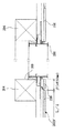
【0009】
ところでこのような調整パネルを、正規パネル202Nの丁度半分の長さの調整パネル202H´(図6参照)としたとき(ピッチPは柱204の芯−芯間のピッチである)、図6に示しているように調整パネル202H´の左右方向端と開口206の左右方向端との間に若干の隙間βが生じることとなる(柱204のサイズは一般に100mm角であり、従ってβは通常約50mm程度である)。
従って上記調整パネル202Hの左右方向長は、少なくとも(L/2)+βとしておくことが必要である。
【0010】
ところが調整パネル202Hの左右方向長を丁度(L/2)+βとしておいたとき、図5(B)に示すように開口206の左側に調整パネル202Hを配置する際には特に問題を生じないが、開口206の右側にこの調整パネル202Hを配置したとき、以下のような不都合が生じる。
【0011】
タイルパネル202を四方决り構造として、上下左右に隣接するタイルパネル同士を相决り嵌合させるようにしたとき、開口206の右側に配置される調整パネル202Hにあっては、右端に位置するタイル200−R1が本来あるべき長さ(左右方向長)よりもβだけ長くなったり、或いはβの長さの半端なタイル片200−R2が残ってしまい(四方决り構造のタイルパネルの場合、パネル同士の相决り嵌合の確保のために、調整パネル202Hの左端側(開口206側)の端部を切除することとなるから)、この結果調整パネル202Hと上下,左右方向に隣接する正規サイズの正規パネル202Nとでタイル配列の規則性が乱れ、タイル意匠が不連続なものとなってしまう不都合を生じるのである。
【0012】
【課題を解決するための手段】
本願の発明はこのような課題を解決するためになされたものである。
而して本発明のタイルパネルの張付工法は、板体表面に複数の左右方向長さが50mm以上のタイルを上下方向に複数段に且つ上下に隣接する各段でタイルの左右方向位置が左右にずれた位置となるように配置して成り、パネル左右端で少なくとも複数段のタイルが半端サイズとなる形態の四方决り構造のタイルパネルを、左右方向に等ピッチPで配設した柱等縦方向に延在する下地材表面に固定してタイルパネルの張付施工を行うタイルパネルの張付工法であって、該タイルパネルとして、パネルの左右方向長Lが該ピッチPの整数倍の大きさで且つ前記タイルの左右方向長が該ピッチPの整数分の1の大きさの正規サイズの正規パネルと、パネルの左右方向長が該正規パネルの左右方向長Lよりも小で該Lの半分よりもαだけ長く且つ該αの大きさがタイル1枚分の大きさとされた、該正規パネルの略半分長の調整パネルとを用意し、該正規パネルの張付可能な箇所においては該正規パネルの左右方向端位置を前記下地材位置に合わせて該左右各端を該下地材に固定する一方、開口の存在によって該正規パネルの張付不能な箇所においては該正規パネル又は該調整パネルを該開口の形状に合わせて一部切断した上で、左右方向端位置を前記下地材位置に合せて各左右各端を該下地材に固定し、タイル面を構築していくことを特徴とする。
【0013】
【作用及び発明の効果】
上記のように本発明は、調整パネルにおける左右方向長を正規パネルの左右方向長Lに対して(L/2)+αと成し且つそのαの大きさをタイル1枚分の大きさと成し、開口の形状に合わせてその一部を切断した調整パネルを用いてタイル張施工を行うようになしたもので、本発明によれば、調整パネルを開口の左側に配置する場合はもとより、開口の右側に配置する場合においても、調整パネルとその上下及び左右のパネルとの間でタイル配列の規則性に乱れを生ぜしめず、タイル壁面の意匠性をそれらパネルの間で連続したものとすることができ、美観の良好なタイル壁面を構築することができる。
【0014】
尚本発明においては、前記開口の左側に位置する部分においては調整パネルの右端側を切断し、開口の右側においては調整パネルの左端側を切断して調整パネルを下地材に固定することとなる。
【0015】
【実施例】
次に本発明の実施例を図面に基づいて詳しく説明する。
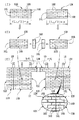
図1において、10は左右方向に等しいピッチPで配設された下地材としての柱で、それら柱10の表面に多数のタイルパネルが張付固定され、それらタイルパネルによってタイル壁面が構築されている。
尚、柱10へのタイルパネルの固定は釘打ちにより或いは柱10に取付固定された固定金具により行われている。
また図中22は躯体側の壁に窓や出入口等を設けるためにタイル壁面に形成された開口である。
【0016】
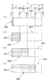
図2(A)はそのタイルパネルにおける正規サイズの正規パネル12Nを示したもので、この正規パネル12Nは、板体14の表面に多数の左右方向長さが50mm以上の陶磁器タイル16を貼着して構成してある。
ここで正規パネル12Nは、タイル16を板体14の表面に馬張りした形態のものである。詳しくは、タイル16を上下複数段に板体14表面に配置するとともに、上下に隣接する各段でタイル16を左右方向に互い違いとなるように配置し、それらを板体14表面に貼着したものである。
【0017】
本例では、パネル左右端の一部タイルを除いて、各タイル16が何れも同じ大きさ,形状のものが用いられている。そして何れかの段のタイル16の左右端が、隣接する上段及び下段のタイル16の丁度左右方向の中央位置に位置するように、各タイル16が配列されている。
【0018】
尚この例において、最上段且つ左右端に位置するタイル16L,16Rが、何れも正規サイズのタイル16Nの丁度半分の長さ(左右方向長さ)とされており、それらの間に位置する各タイル16が正規サイズのタイル16Nとされている。
【0019】
また最上段の直ぐ下の次段のタイル16については、全てが正規サイズのタイル16Nとされている。更にその下の段のタイル配列は最上段のタイル配列と同じとされており、以下同様に一段毎にタイル配列が同様の配列とされている。
【0020】
正規パネル12Nは、四方决り構造とされており、板体14の上縁に沿って全長に亘り嵌合突部18が形成され、また右端縁に沿って全高に亘り嵌合突部18が形成されている。また下縁に沿って全長に亘り対応する嵌合凹部20が形成され、更に左端縁に沿って同様の嵌合凹部20が形成されている。
【0021】
尚この例では、柱10間のピッチPは455mmとされており、また正規パネル12Nの左右方向長L1はピッチPの4倍の長さ、即ち1820mmとされている。また正規サイズのタイル16Nの左右方向長は、ピッチPの1/2の長さ(約227.5mm)とされている。
従ってこの例において、正規パネル12Nには左右方向に8枚ないし8枚相当分のタイル16が配置され、板体14上に貼着されている。
またこの例では、正規パネル12Nにおいてタイル16の上下方向の段数は6段とされている。
【0022】
続いて図2(B)はタイルパネルにおける調整パネル12Hを示したもので、この調整パネル12Hの基本的な形態は、正規パネル12Nと同様の形態とされている。
即ち調整パネル12Hにおいてもまた、正規パネル12Nと同様にタイル16が板体14の表面に馬張りされているとともに、四方决り構造とされている。
【0023】
一方この調整パネル12Hは、その左右方向長L2が正規パネル12Nの長さL1に対して小さい、(L1/2)+αの長さとされている。そしてそのαは50mmよりも大きい長さ、詳しくは正規サイズのタイル16Nの1枚分の長さ(約227.5mm)とされている。
従って、調整パネル12Hにおけるパネル右端のタイル配列は正規パネル12Nにおけるパネル右端のタイル配列と同じとなり、また調整パネル12Hにおけるパネル左端のタイル配列は、正規パネル12Nにおけるパネル左端のタイル配列と全く同様となっている。
【0024】
尚、図2(B)に示すように本例の調整パネル12Hは、左右方向に5枚ないし5枚相当分のタイル16が、また上下方向に6段のタイル16が配置されている。
【0025】
図1及び図3に示すタイル壁面には、タイルパネル列b列とc列とにまたがって、その幅が正規パネル12Nの左右方向長とほぼ同じの開口22が設けられている。
この開口22の上端縁はタイル壁面の最も上側のタイルパネルの上下方向ほぼ中間位置に位置している。
【0026】
次に図1及び図3に示すタイル壁面の例を基に、本例の工法によるタイル壁面の構築手順について以下に説明する。
先ず図1中左端のa列については、正規パネル12Nを切断することなくそのままこれを用いることができる。また同様に同図中右端のd列についても、正規パネル12Nを切断することなくそのまま使用することができる。
【0027】
次にb列は、その列の図中右端から左右方向中央に位置する柱10まで開口22が形成されていることから、その開口22の左側にタイルパネルの張付けを行うこととなる。そしてこのb列においては、正規パネル12Nより左右方向長が短い調整パネル12Hを用いる。
これは、b列においては必要とするタイルパネルの左右方向長が正規パネル12Nのおよそ半分であり、図7にも示すように正規パネル12Nを使用する場合、切断ロスが大きくなってしまうためである。
【0028】
このb列においては、調整パネル12Hの右端部を一部切断することによって、その左右方向長を正規パネル12Nの左右方向長L1に対し(L1/2)+β(本例ではβは柱10の幅100mmの半分の50mm)とし、その左右端を柱10に釘打ち或いは柱10に取付固定した固定金具により柱10に固定して開口22の左側のタイル壁面を構築する。
このとき調整パネル12Hは左端縁をa列の正規パネル12Nに対して合决り嵌合させ、また上下方向において調整パネル12H同士を上下方向に合决り嵌合させた状態とする。
【0029】
尚最上段のタイルパネルについては正規パネル12Nを用い、その一部を開口22の形状に合わせて切断した上で使用する。
続くc列の最上段のタイルパネルについても正規パネル12Nを用い、その一部を開口22の形状に合わせて切断した上で使用する。
【0030】
次にc列については、b列と同様にタイルパネルとして調整パネル12Hを用いてこれを柱10に固定しタイル壁面を構築する。
このとき各調整パネル12Hはその左端部を一部切断することによって必要な左右長さに調整する。具体的には、左右方向長が(L1/2)+βとなるように各調整パネル12Hの左端部を切断する。そしてその各左右端を開口22の右側において柱10に止付固定しタイル壁面を構築する。
【0031】
このc列においては、各調整パネル12Hの右端縁をd列の正規パネル12Nに対し左右方向に合决り嵌合させるとともに、上下方向において各調整パネル12Hを合决り嵌合させる。
尚下から3段目の調整パネル12Hについては、その上縁を最上段の正規パネル12Nの下縁に対して合决り嵌合させる。
【0032】
本例の張付工法において、開口22の右側に位置するc列の各調整パネル12Hとc列最上段の正規パネル12N及びそれらの更に右側のd列の正規パネル12Nとの合せ部において、各パネルのタイル配列は図3(III)に示しているように乱れのない規則性を持ったものとなり、それらパネル間でタイル壁面の意匠性が連続したものとなる。
【0033】
本例の張付工法において、調整パネル12Hはパネル右端のタイル配列が正規パネル12Nのそれと同じタイル配列とされており、且つパネル張付けに際して開口22の右側においては、その左端部を切断して用いているからである。
【0034】
このように本例の張付工法によれば、調整パネル12Hを開口22の左側に配置する場合はもとより、開口22の右側に配置する場合においても、調整パネル12Hとその上下及び左右の正規パネル12Nとの間でタイル配列の規則性に乱れを生ぜしめず、タイル壁面の意匠性をそれらタイルパネル間で連続性を持たせることができ、美観の良好なタイル壁面を構築することができる。
【0035】
また本例によれば、調整パネル12Hを用いることで、タイルパネルの切断ロスを効果的に少なくすることができ、タイルパネルに要するコストを低減することが可能である。
【0036】
以上本発明の実施例を詳述したがこれはあくまで一例示である。
例えば上例ではタイルパネルの左右端のタイル16L,タイル16Rともに正規タイル16Nの丁度半分の左右方向長としているが、右端及び左端の何れか一方のタイルの左右方向長を2/3とし、他方を1/3とすること、或いは左右端のタイル16L,16Rを合わせた長さがタイル16Nの1枚分となるようにタイルサイズをそれ以外のサイズとすることが可能である。また本発明は上記馬張り以外のタイル配列であっても、上下に隣接する各段でタイルの左右方向位置を左右にずらしてタイルを配置してタイルパネルを構成し、それらタイルパネルを用いてタイル面を施工するに際して一般的に適用可能である。
例えばイギリス張り,フランス張り等その他パターンでタイル配列してなるタイルパネルを用いてタイル面を構築するに際しても適用可能である。その他本発明はその主旨を逸脱しない範囲において種々変更を加えた形態で構成可能である。
【図面の簡単な説明】
【図1】 本発明の一実施例であるタイルパネルの張付工法を、開口を有するタイル壁面に適用した図である。
【図2】 図1のタイルパネルにおける正規パネルと調整パネルとをそれぞれ単品で示す図である。
【図3】 図1の張付工法を具体的に説明するための説明図である。
【図4】 タイルを通し張りし、又は馬張りして成るタイルパネルを示す図である。
【図5】 図4の馬張りしたタイルパネルを用いた場合の不具合の説明図である。
【図6】 図5における開口部と周辺部の断面を拡大して示す図である。
【図7】 図5における開口のパターンとタイルパネルの切断パターンとを併せて示す図である。
【符号の説明】
10 柱
12N 正規パネル
12H 調整パネル
14 板体
16,16N,16R,16L タイル
22 開口[0001]
BACKGROUND OF THE INVENTION
The present invention relates to a tile panel sticking method, and more particularly to a technical means for reducing a cutting loss of a tile panel.
[0002]
[Prior art and problems to be solved by the invention]
Conventionally, as a means for forming the tile wall surface, for example, a method of attaching individual ceramic tiles to the surface of the base material by wet or dry bonding and a method in which a plurality of tiles are pasted on the surface of the plate in advance to form a panel. A method of fixing the tile panel to the surface of the base material on the side of the casing extending in the vertical direction such as a pillar is performed.
[0003]
As the latter method, that is, a method of fixing the tile panel to the surface of the base material, tiles are stretched through the surface of the plate body, and more specifically, as shown in FIG. Each
[0004]
FIG. 5 illustrates a method using the latter Mabari type tile panel. A
[0005]
Incidentally, as shown in FIGS. 5 (B) and (II), when there is an
Here, since the opening 206 is attached to the
[0006]
FIG. 7 shows the pattern of the position and size of the
In the figure, (D) shows an example in which openings 206d having the same length in the left-right direction as the pitch P between the
[0007]
Here, when the horizontal length L of the
[0008]
However, if this is done, a large cutting loss occurs in the
Therefore, in addition to the
In this way, the cutting loss in the
[0009]
By the way, when such an adjustment panel is an
Therefore, the length in the left-right direction of the
[0010]
However, when the length of the
[0011]
When the
[0012]
[Means for Solving the Problems]
The invention of the present application has been made to solve such problems.
Thus, the tile paneling method according to the present invention includes a plurality of tiles having a length of 50 mm or more on the surface of the plate body in the vertical direction, and the horizontal positions of the tiles are vertically adjacent to each other. Columns that are arranged so as to be shifted to the left and right, and are tile panels having a four-sided structure in which at least a plurality of tiles have half-end sizes at the left and right ends of the panel, and are arranged at equal pitches P in the left-right direction. A tile panel tensioning method in which tile panels are fixed to a surface of a base material extending in an equal longitudinal direction, and the horizontal length L of the panel is an integral multiple of the pitch P. And a regular panel having a regular size in which the horizontal length of the tile is a fraction of an integer of the pitch P, and the horizontal length of the panel is smaller than the horizontal length L of the regular panel. Longer than half of L by α and the α Of the sized backlash yl size of one sheet, prepared and adjustment panel substantially half length of the normal panel, a left-right direction end position of the normal panel in Chozuke where possible of the normal panel The right and left ends are fixed to the base material in accordance with the position of the base material, and the regular panel or the adjustment panel is adjusted to the shape of the opening at a location where the regular panel cannot be attached due to the presence of the opening. The tile surface is constructed by cutting a part and fixing the left and right ends to the base material by aligning the left and right end positions with the base material position.
[0013]
[Operation and effect of the invention]
The present invention as described above, the lateral direction length in the adjustment panel normal panel with respect to the lateral direction length L (L / 2) + α and forms and forms the magnitude of the alpha and the size of one sheet tile , which was no to perform tile Zhang applied using a part of the cut was adjusted panel in accordance with the shape of the opening, according to the present invention, when arranging the adjustment panel on the left side of the opening as well, Even when it is placed on the right side of the opening, the regularity of the tile arrangement is not disturbed between the adjustment panel and the upper and lower and left and right panels, and the design of the tile wall is continuous between the panels. It is possible to construct a tile wall surface with good aesthetics.
[0014]
In the present invention, the adjustment panel is fixed to the base material by cutting the right end side of the adjustment panel at the portion located on the left side of the opening and cutting the left end side of the adjustment panel on the right side of the opening. .
[0015]
【Example】
Next, embodiments of the present invention will be described in detail with reference to the drawings.
In FIG. 1,
Note that the tile panel is fixed to the
In the figure,
[0016]
FIG. 2A shows a
Here, the
[0017]
In this example, except for some tiles at the left and right ends of the panel, each
[0018]
In this example, the
[0019]
In addition, all the
[0020]
The
[0021]
In this example, the pitch P between the
Therefore, in this example, eight or eight
Further, in this example, the number of
[0022]
Next, FIG. 2B shows an
That is, in the
[0023]
On the other hand this
Accordingly, the tile arrangement at the right end of the panel in the
[0024]
As shown in FIG. 2B, in the
[0025]
The tile wall surface shown in FIGS. 1 and 3 is provided with an
The upper end edge of the
[0026]
Next, based on the example of the tile wall surface shown in FIG.1 and FIG.3, the construction procedure of the tile wall surface by the construction method of this example is demonstrated below.
First, the a-column at the left end in FIG. 1 can be used as it is without cutting the
[0027]
Next, in the row b, since the
This is because, in the row b, the required length of the tile panel in the left-right direction is about half that of the
[0028]
In this column b, by cutting a portion of the right end portion of the
At this time, the
[0029]
For the uppermost tile panel, the
The
[0030]
Next, as for the column c, the tile wall surface is constructed by fixing the
At this time, each
[0031]
In this c row, the right end edge of each
Note that the upper edge of the
[0032]
In the pasting method of the present example, each
[0033]
In the pasting method of this example, the
[0034]
As described above, according to the pasting method of this example, the
[0035]
Further, according to this example, by using the
[0036]
Although the embodiment of the present invention has been described in detail above, this is merely an example.
For example, in the above example, both the left and
For example, the present invention can be applied to constructing a tile surface using a tile panel formed by arranging tiles with other patterns such as British or French. In addition, this invention can be comprised in the form which added the various change in the range which does not deviate from the main point.
[Brief description of the drawings]
FIG. 1 is a diagram in which a tile panel sticking method according to an embodiment of the present invention is applied to a tile wall surface having an opening.
FIG. 2 is a diagram showing a regular panel and an adjustment panel in the tile panel of FIG.
FIG. 3 is an explanatory diagram for specifically explaining the pasting method of FIG. 1;
FIG. 4 is a diagram showing a tile panel in which tiles are stretched through or mounted on a horse.
FIG. 5 is an explanatory diagram of a problem in the case where the horse-mounted tile panel of FIG. 4 is used.
6 is an enlarged view showing a cross section of an opening and a peripheral portion in FIG. 5. FIG.
7 is a diagram showing both the opening pattern and the tile panel cutting pattern in FIG. 5; FIG.
[Explanation of symbols]
10
Claims (1)
該タイルパネルとして、パネルの左右方向長Lが該ピッチPの整数倍の大きさで且つ前記タイルの左右方向長が該ピッチPの整数分の1の大きさの正規サイズの正規パネルと、パネルの左右方向長が該正規パネルの左右方向長Lよりも小で該Lの半分よりもαだけ長く且つ該αの大きさがタイル1枚分の大きさとされた、該正規パネルの略半分長の調整パネルとを用意し、該正規パネルの張付可能な箇所においては該正規パネルの左右方向端位置を前記下地材位置に合わせて該左右各端を該下地材に固定する一方、開口の存在によって該正規パネルの張付不能な箇所においては該正規パネル又は該調整パネルを該開口の形状に合わせて一部切断した上で、左右方向端位置を前記下地材位置に合せて各左右各端を該下地材に固定し、タイル面を構築していくことを特徴とするタイルパネルの張付工法。A plurality of tiles having a length of 50 mm or more on the surface of the plate body are arranged so that the left and right positions of the tiles are shifted to the left and right in each step adjacent to the top and bottom in a plurality of steps in the vertical direction, Fix a tile panel with a four-sided structure in which at least multiple tiles at the left and right ends of the panel are half-end size to the surface of the base material extending in the vertical direction such as pillars arranged at equal pitch P in the left and right direction It is a tile panel sticking method for attaching tile panels,
As the tile panel, a normal panel having a normal size in which the horizontal length L of the panel is an integral multiple of the pitch P and the horizontal length of the tile is a fraction of an integer of the pitch P; lateral direction length is sized backlash yl size of one sheet only long and the alpha alpha than half of the L small than the lateral direction length L of the normal panel, approximately half of the normal panel A long adjustment panel is prepared, and in the place where the regular panel can be attached, the right and left ends of the regular panel are aligned with the base material position and the left and right ends are fixed to the base material, while the opening is opened. In a place where the regular panel cannot be attached due to the presence of the regular panel, the regular panel or the adjustment panel is partially cut according to the shape of the opening , and the left and right end positions are aligned with the base material position. Fix each end to the base material and configure the tile surface. Tile panel sticking method characterized by building.
Priority Applications (1)
| Application Number | Priority Date | Filing Date | Title |
|---|---|---|---|
| JP10870998A JP3832967B2 (en) | 1998-04-03 | 1998-04-03 | Tile panel sticking method |
Applications Claiming Priority (1)
| Application Number | Priority Date | Filing Date | Title |
|---|---|---|---|
| JP10870998A JP3832967B2 (en) | 1998-04-03 | 1998-04-03 | Tile panel sticking method |
Publications (2)
| Publication Number | Publication Date |
|---|---|
| JPH11287028A JPH11287028A (en) | 1999-10-19 |
| JP3832967B2 true JP3832967B2 (en) | 2006-10-11 |
Family
ID=14491621
Family Applications (1)
| Application Number | Title | Priority Date | Filing Date |
|---|---|---|---|
| JP10870998A Expired - Fee Related JP3832967B2 (en) | 1998-04-03 | 1998-04-03 | Tile panel sticking method |
Country Status (1)
| Country | Link |
|---|---|
| JP (1) | JP3832967B2 (en) |
-
1998
- 1998-04-03 JP JP10870998A patent/JP3832967B2/en not_active Expired - Fee Related
Also Published As
| Publication number | Publication date |
|---|---|
| JPH11287028A (en) | 1999-10-19 |
Similar Documents
| Publication | Publication Date | Title |
|---|---|---|
| CA2032536A1 (en) | Rigid grating mat with unidirectional elements | |
| JP4295903B2 (en) | Panel mounting structure and handrail structure | |
| JP3832967B2 (en) | Tile panel sticking method | |
| KR20120045593A (en) | The finishing structure for building and method using that | |
| JP4384574B2 (en) | Roof parapet ventilation structure | |
| JP4391446B2 (en) | Foundation packing | |
| JP2004308277A (en) | Building unit and outer wall panel | |
| JP7387148B2 (en) | Panel support jig | |
| JP2007291812A (en) | Tile backing panel, and tile installing method for wall | |
| JP6514435B2 (en) | Building board and its mounting structure and tacking structure | |
| JP3302464B2 (en) | Building wall construction method | |
| JP4970139B2 (en) | Unit building with atrium | |
| WO2019178384A1 (en) | Method of integrating solar panels in the roof substrate structure | |
| JP2730801B2 (en) | ALC panel | |
| JP4117845B2 (en) | External structure and L-shaped member for external structure | |
| JPH02293104A (en) | Concrete shuttering device for making concrete slab | |
| JPH09228514A (en) | Wall panel for framing construction method | |
| JP3128689B2 (en) | Structure of ventilation layer in building | |
| JP2972076B2 (en) | Exterior wall panel installation structure | |
| JP2002294971A (en) | Execution method of decorative laminated sheet | |
| JP2001132093A (en) | Entrance porch installing structure | |
| JP2001214528A (en) | Building unit, unit building and wall panel | |
| JP2006214108A (en) | Building by wood frame construction | |
| JPH0321705B2 (en) | ||
| JP2000136594A (en) | Ceramic panel structure |
Legal Events
| Date | Code | Title | Description |
|---|---|---|---|
| A977 | Report on retrieval |
Free format text: JAPANESE INTERMEDIATE CODE: A971007 Effective date: 20050801 |
|
| A131 | Notification of reasons for refusal |
Free format text: JAPANESE INTERMEDIATE CODE: A131 Effective date: 20051018 |
|
| A131 | Notification of reasons for refusal |
Free format text: JAPANESE INTERMEDIATE CODE: A131 Effective date: 20060328 |
|
| A521 | Written amendment |
Free format text: JAPANESE INTERMEDIATE CODE: A523 Effective date: 20060526 |
|
| TRDD | Decision of grant or rejection written | ||
| A01 | Written decision to grant a patent or to grant a registration (utility model) |
Free format text: JAPANESE INTERMEDIATE CODE: A01 Effective date: 20060711 |
|
| A61 | First payment of annual fees (during grant procedure) |
Free format text: JAPANESE INTERMEDIATE CODE: A61 Effective date: 20060718 |
|
| R150 | Certificate of patent or registration of utility model |
Free format text: JAPANESE INTERMEDIATE CODE: R150 |
|
| LAPS | Cancellation because of no payment of annual fees |