JP3813633B2 - Component carrier tape with electrostatic dissipation characteristics - Google Patents
Component carrier tape with electrostatic dissipation characteristics Download PDFInfo
- Publication number
- JP3813633B2 JP3813633B2 JP51194797A JP51194797A JP3813633B2 JP 3813633 B2 JP3813633 B2 JP 3813633B2 JP 51194797 A JP51194797 A JP 51194797A JP 51194797 A JP51194797 A JP 51194797A JP 3813633 B2 JP3813633 B2 JP 3813633B2
- Authority
- JP
- Japan
- Prior art keywords
- strip portion
- cover
- carrier tape
- carrier
- tape
- Prior art date
- Legal status (The legal status is an assumption and is not a legal conclusion. Google has not performed a legal analysis and makes no representation as to the accuracy of the status listed.)
- Expired - Lifetime
Links
- 239000000463 material Substances 0.000 claims description 40
- 230000003068 static effect Effects 0.000 claims description 24
- 239000000853 adhesive Substances 0.000 claims description 23
- 230000001070 adhesive effect Effects 0.000 claims description 23
- -1 alkyl methacrylate Chemical compound 0.000 claims description 12
- 239000004417 polycarbonate Substances 0.000 claims description 12
- 229920000515 polycarbonate Polymers 0.000 claims description 12
- 229920000728 polyester Polymers 0.000 claims description 7
- 238000003860 storage Methods 0.000 claims description 6
- 230000007246 mechanism Effects 0.000 claims description 5
- 230000002829 reductive effect Effects 0.000 claims description 5
- CERQOIWHTDAKMF-UHFFFAOYSA-M Methacrylate Chemical compound CC(=C)C([O-])=O CERQOIWHTDAKMF-UHFFFAOYSA-M 0.000 claims description 4
- 125000005250 alkyl acrylate group Chemical group 0.000 claims description 4
- 125000000217 alkyl group Chemical group 0.000 claims description 4
- 230000000694 effects Effects 0.000 claims description 4
- 230000008030 elimination Effects 0.000 claims description 4
- 238000003379 elimination reaction Methods 0.000 claims description 4
- 150000004820 halides Chemical class 0.000 claims description 4
- 125000005208 trialkylammonium group Chemical group 0.000 claims description 4
- MPNXSZJPSVBLHP-UHFFFAOYSA-N 2-chloro-n-phenylpyridine-3-carboxamide Chemical compound ClC1=NC=CC=C1C(=O)NC1=CC=CC=C1 MPNXSZJPSVBLHP-UHFFFAOYSA-N 0.000 claims description 3
- VVQNEPGJFQJSBK-UHFFFAOYSA-N Methyl methacrylate Chemical compound COC(=O)C(C)=C VVQNEPGJFQJSBK-UHFFFAOYSA-N 0.000 claims description 3
- CQEYYJKEWSMYFG-UHFFFAOYSA-N butyl acrylate Chemical compound CCCCOC(=O)C=C CQEYYJKEWSMYFG-UHFFFAOYSA-N 0.000 claims description 3
- SUPCQIBBMFXVTL-UHFFFAOYSA-N ethyl 2-methylprop-2-enoate Chemical compound CCOC(=O)C(C)=C SUPCQIBBMFXVTL-UHFFFAOYSA-N 0.000 claims description 3
- 238000005304 joining Methods 0.000 claims description 3
- 239000007795 chemical reaction product Substances 0.000 claims 3
- 238000000576 coating method Methods 0.000 description 36
- 239000011248 coating agent Substances 0.000 description 35
- 230000000052 comparative effect Effects 0.000 description 29
- 238000000034 method Methods 0.000 description 16
- 230000032683 aging Effects 0.000 description 14
- 238000007789 sealing Methods 0.000 description 14
- LFQSCWFLJHTTHZ-UHFFFAOYSA-N Ethanol Chemical compound CCO LFQSCWFLJHTTHZ-UHFFFAOYSA-N 0.000 description 11
- XLYOFNOQVPJJNP-UHFFFAOYSA-N water Substances O XLYOFNOQVPJJNP-UHFFFAOYSA-N 0.000 description 10
- 239000010410 layer Substances 0.000 description 9
- 239000012790 adhesive layer Substances 0.000 description 8
- 238000003856 thermoforming Methods 0.000 description 8
- 238000009825 accumulation Methods 0.000 description 7
- 239000002904 solvent Substances 0.000 description 7
- ZWEHNKRNPOVVGH-UHFFFAOYSA-N 2-Butanone Chemical compound CCC(C)=O ZWEHNKRNPOVVGH-UHFFFAOYSA-N 0.000 description 6
- 239000002216 antistatic agent Substances 0.000 description 6
- 239000000243 solution Substances 0.000 description 6
- 230000005611 electricity Effects 0.000 description 5
- 238000004519 manufacturing process Methods 0.000 description 5
- 229920003023 plastic Polymers 0.000 description 5
- 239000004033 plastic Substances 0.000 description 5
- 229920000642 polymer Polymers 0.000 description 5
- 239000007787 solid Substances 0.000 description 5
- 229920001169 thermoplastic Polymers 0.000 description 5
- 230000002411 adverse Effects 0.000 description 4
- 239000011230 binding agent Substances 0.000 description 4
- 238000005259 measurement Methods 0.000 description 4
- 230000008569 process Effects 0.000 description 4
- 229920005989 resin Polymers 0.000 description 4
- 239000011347 resin Substances 0.000 description 4
- OKKJLVBELUTLKV-UHFFFAOYSA-N Methanol Chemical compound OC OKKJLVBELUTLKV-UHFFFAOYSA-N 0.000 description 3
- 239000004793 Polystyrene Substances 0.000 description 3
- 239000000356 contaminant Substances 0.000 description 3
- 238000001816 cooling Methods 0.000 description 3
- 238000010586 diagram Methods 0.000 description 3
- 230000008034 disappearance Effects 0.000 description 3
- 239000000428 dust Substances 0.000 description 3
- 239000005038 ethylene vinyl acetate Substances 0.000 description 3
- 229920001200 poly(ethylene-vinyl acetate) Polymers 0.000 description 3
- 229920000098 polyolefin Polymers 0.000 description 3
- 229920002223 polystyrene Polymers 0.000 description 3
- 239000007921 spray Substances 0.000 description 3
- 238000007655 standard test method Methods 0.000 description 3
- 239000004416 thermosoftening plastic Substances 0.000 description 3
- 239000004698 Polyethylene Substances 0.000 description 2
- 239000004743 Polypropylene Substances 0.000 description 2
- 239000003990 capacitor Substances 0.000 description 2
- 239000006229 carbon black Substances 0.000 description 2
- 239000004020 conductor Substances 0.000 description 2
- 230000007423 decrease Effects 0.000 description 2
- GNTDGMZSJNCJKK-UHFFFAOYSA-N divanadium pentaoxide Chemical compound O=[V](=O)O[V](=O)=O GNTDGMZSJNCJKK-UHFFFAOYSA-N 0.000 description 2
- 230000009977 dual effect Effects 0.000 description 2
- 238000001125 extrusion Methods 0.000 description 2
- 230000001771 impaired effect Effects 0.000 description 2
- 239000000203 mixture Substances 0.000 description 2
- 230000036961 partial effect Effects 0.000 description 2
- 229920000058 polyacrylate Polymers 0.000 description 2
- 229920000573 polyethylene Polymers 0.000 description 2
- 229920000139 polyethylene terephthalate Polymers 0.000 description 2
- 239000005020 polyethylene terephthalate Substances 0.000 description 2
- 229920001155 polypropylene Polymers 0.000 description 2
- 239000000523 sample Substances 0.000 description 2
- 229920003048 styrene butadiene rubber Polymers 0.000 description 2
- 239000000126 substance Substances 0.000 description 2
- 239000004094 surface-active agent Substances 0.000 description 2
- 229920001897 terpolymer Polymers 0.000 description 2
- 229910001887 tin oxide Inorganic materials 0.000 description 2
- 238000011179 visual inspection Methods 0.000 description 2
- 150000000565 5-membered heterocyclic compounds Chemical class 0.000 description 1
- 150000000644 6-membered heterocyclic compounds Chemical class 0.000 description 1
- NIXOWILDQLNWCW-UHFFFAOYSA-M Acrylate Chemical compound [O-]C(=O)C=C NIXOWILDQLNWCW-UHFFFAOYSA-M 0.000 description 1
- 229920000178 Acrylic resin Polymers 0.000 description 1
- 239000004925 Acrylic resin Substances 0.000 description 1
- HCLZZCCPFFHZAX-UHFFFAOYSA-N CC(CN)(C(C1)CC2)C=C1C1C2=CC1 Chemical compound CC(CN)(C(C1)CC2)C=C1C1C2=CC1 HCLZZCCPFFHZAX-UHFFFAOYSA-N 0.000 description 1
- 239000004677 Nylon Substances 0.000 description 1
- 239000004820 Pressure-sensitive adhesive Substances 0.000 description 1
- BZHJMEDXRYGGRV-UHFFFAOYSA-N Vinyl chloride Chemical compound ClC=C BZHJMEDXRYGGRV-UHFFFAOYSA-N 0.000 description 1
- 229920002433 Vinyl chloride-vinyl acetate copolymer Polymers 0.000 description 1
- 229920005822 acrylic binder Polymers 0.000 description 1
- XECAHXYUAAWDEL-UHFFFAOYSA-N acrylonitrile butadiene styrene Chemical compound C=CC=C.C=CC#N.C=CC1=CC=CC=C1 XECAHXYUAAWDEL-UHFFFAOYSA-N 0.000 description 1
- 229920000122 acrylonitrile butadiene styrene Polymers 0.000 description 1
- 239000004676 acrylonitrile butadiene styrene Substances 0.000 description 1
- 238000004026 adhesive bonding Methods 0.000 description 1
- 238000005054 agglomeration Methods 0.000 description 1
- 230000002776 aggregation Effects 0.000 description 1
- XXLJGBGJDROPKW-UHFFFAOYSA-N antimony;oxotin Chemical compound [Sb].[Sn]=O XXLJGBGJDROPKW-UHFFFAOYSA-N 0.000 description 1
- 238000003491 array Methods 0.000 description 1
- 230000000712 assembly Effects 0.000 description 1
- 238000000429 assembly Methods 0.000 description 1
- 230000001680 brushing effect Effects 0.000 description 1
- 239000003985 ceramic capacitor Substances 0.000 description 1
- 230000008859 change Effects 0.000 description 1
- 239000012612 commercial material Substances 0.000 description 1
- 239000011231 conductive filler Substances 0.000 description 1
- 239000012050 conventional carrier Substances 0.000 description 1
- 230000001627 detrimental effect Effects 0.000 description 1
- 238000007598 dipping method Methods 0.000 description 1
- 238000005553 drilling Methods 0.000 description 1
- 238000001035 drying Methods 0.000 description 1
- 230000005686 electrostatic field Effects 0.000 description 1
- 230000007613 environmental effect Effects 0.000 description 1
- 230000006870 function Effects 0.000 description 1
- 230000009477 glass transition Effects 0.000 description 1
- 125000005842 heteroatom Chemical group 0.000 description 1
- 150000002391 heterocyclic compounds Chemical class 0.000 description 1
- 238000010348 incorporation Methods 0.000 description 1
- 238000001746 injection moulding Methods 0.000 description 1
- 238000003780 insertion Methods 0.000 description 1
- 230000037431 insertion Effects 0.000 description 1
- 239000011229 interlayer Substances 0.000 description 1
- 238000005342 ion exchange Methods 0.000 description 1
- 238000010030 laminating Methods 0.000 description 1
- 239000007788 liquid Substances 0.000 description 1
- 230000007774 longterm Effects 0.000 description 1
- 238000002844 melting Methods 0.000 description 1
- 230000008018 melting Effects 0.000 description 1
- 229910044991 metal oxide Inorganic materials 0.000 description 1
- 150000004706 metal oxides Chemical class 0.000 description 1
- 238000012986 modification Methods 0.000 description 1
- 230000004048 modification Effects 0.000 description 1
- 239000002736 nonionic surfactant Substances 0.000 description 1
- 229920001778 nylon Polymers 0.000 description 1
- 230000003287 optical effect Effects 0.000 description 1
- 239000007800 oxidant agent Substances 0.000 description 1
- 239000002245 particle Substances 0.000 description 1
- 239000003348 petrochemical agent Substances 0.000 description 1
- 239000002985 plastic film Substances 0.000 description 1
- 229920006255 plastic film Polymers 0.000 description 1
- 229920006254 polymer film Polymers 0.000 description 1
- 239000002861 polymer material Substances 0.000 description 1
- 239000002952 polymeric resin Substances 0.000 description 1
- 238000006116 polymerization reaction Methods 0.000 description 1
- 239000004800 polyvinyl chloride Substances 0.000 description 1
- 229920000915 polyvinyl chloride Polymers 0.000 description 1
- 238000007781 pre-processing Methods 0.000 description 1
- 230000001737 promoting effect Effects 0.000 description 1
- 230000029058 respiratory gaseous exchange Effects 0.000 description 1
- 230000002441 reversible effect Effects 0.000 description 1
- 239000012945 sealing adhesive Substances 0.000 description 1
- 239000004065 semiconductor Substances 0.000 description 1
- 230000035945 sensitivity Effects 0.000 description 1
- 229910052708 sodium Inorganic materials 0.000 description 1
- 239000011734 sodium Substances 0.000 description 1
- 239000011877 solvent mixture Substances 0.000 description 1
- 238000005507 spraying Methods 0.000 description 1
- 230000002459 sustained effect Effects 0.000 description 1
- 229920003002 synthetic resin Polymers 0.000 description 1
- 238000010998 test method Methods 0.000 description 1
- 239000012815 thermoplastic material Substances 0.000 description 1
- XOLBLPGZBRYERU-UHFFFAOYSA-N tin dioxide Chemical compound O=[Sn]=O XOLBLPGZBRYERU-UHFFFAOYSA-N 0.000 description 1
- 238000001771 vacuum deposition Methods 0.000 description 1
- 238000007666 vacuum forming Methods 0.000 description 1
- 238000004804 winding Methods 0.000 description 1
Images
Classifications
-
- H—ELECTRICITY
- H05—ELECTRIC TECHNIQUES NOT OTHERWISE PROVIDED FOR
- H05K—PRINTED CIRCUITS; CASINGS OR CONSTRUCTIONAL DETAILS OF ELECTRIC APPARATUS; MANUFACTURE OF ASSEMBLAGES OF ELECTRICAL COMPONENTS
- H05K13/00—Apparatus or processes specially adapted for manufacturing or adjusting assemblages of electric components
- H05K13/003—Placing of components on belts holding the terminals
-
- Y—GENERAL TAGGING OF NEW TECHNOLOGICAL DEVELOPMENTS; GENERAL TAGGING OF CROSS-SECTIONAL TECHNOLOGIES SPANNING OVER SEVERAL SECTIONS OF THE IPC; TECHNICAL SUBJECTS COVERED BY FORMER USPC CROSS-REFERENCE ART COLLECTIONS [XRACs] AND DIGESTS
- Y10—TECHNICAL SUBJECTS COVERED BY FORMER USPC
- Y10S—TECHNICAL SUBJECTS COVERED BY FORMER USPC CROSS-REFERENCE ART COLLECTIONS [XRACs] AND DIGESTS
- Y10S428/00—Stock material or miscellaneous articles
- Y10S428/922—Static electricity metal bleed-off metallic stock
-
- Y—GENERAL TAGGING OF NEW TECHNOLOGICAL DEVELOPMENTS; GENERAL TAGGING OF CROSS-SECTIONAL TECHNOLOGIES SPANNING OVER SEVERAL SECTIONS OF THE IPC; TECHNICAL SUBJECTS COVERED BY FORMER USPC CROSS-REFERENCE ART COLLECTIONS [XRACs] AND DIGESTS
- Y10—TECHNICAL SUBJECTS COVERED BY FORMER USPC
- Y10T—TECHNICAL SUBJECTS COVERED BY FORMER US CLASSIFICATION
- Y10T428/00—Stock material or miscellaneous articles
- Y10T428/14—Layer or component removable to expose adhesive
- Y10T428/1424—Halogen containing compound
-
- Y—GENERAL TAGGING OF NEW TECHNOLOGICAL DEVELOPMENTS; GENERAL TAGGING OF CROSS-SECTIONAL TECHNOLOGIES SPANNING OVER SEVERAL SECTIONS OF THE IPC; TECHNICAL SUBJECTS COVERED BY FORMER USPC CROSS-REFERENCE ART COLLECTIONS [XRACs] AND DIGESTS
- Y10—TECHNICAL SUBJECTS COVERED BY FORMER USPC
- Y10T—TECHNICAL SUBJECTS COVERED BY FORMER US CLASSIFICATION
- Y10T428/00—Stock material or miscellaneous articles
- Y10T428/14—Layer or component removable to expose adhesive
- Y10T428/1471—Protective layer
-
- Y—GENERAL TAGGING OF NEW TECHNOLOGICAL DEVELOPMENTS; GENERAL TAGGING OF CROSS-SECTIONAL TECHNOLOGIES SPANNING OVER SEVERAL SECTIONS OF THE IPC; TECHNICAL SUBJECTS COVERED BY FORMER USPC CROSS-REFERENCE ART COLLECTIONS [XRACs] AND DIGESTS
- Y10—TECHNICAL SUBJECTS COVERED BY FORMER USPC
- Y10T—TECHNICAL SUBJECTS COVERED BY FORMER US CLASSIFICATION
- Y10T428/00—Stock material or miscellaneous articles
- Y10T428/14—Layer or component removable to expose adhesive
- Y10T428/1476—Release layer
-
- Y—GENERAL TAGGING OF NEW TECHNOLOGICAL DEVELOPMENTS; GENERAL TAGGING OF CROSS-SECTIONAL TECHNOLOGIES SPANNING OVER SEVERAL SECTIONS OF THE IPC; TECHNICAL SUBJECTS COVERED BY FORMER USPC CROSS-REFERENCE ART COLLECTIONS [XRACs] AND DIGESTS
- Y10—TECHNICAL SUBJECTS COVERED BY FORMER USPC
- Y10T—TECHNICAL SUBJECTS COVERED BY FORMER US CLASSIFICATION
- Y10T428/00—Stock material or miscellaneous articles
- Y10T428/14—Layer or component removable to expose adhesive
- Y10T428/149—Sectional layer removable
-
- Y—GENERAL TAGGING OF NEW TECHNOLOGICAL DEVELOPMENTS; GENERAL TAGGING OF CROSS-SECTIONAL TECHNOLOGIES SPANNING OVER SEVERAL SECTIONS OF THE IPC; TECHNICAL SUBJECTS COVERED BY FORMER USPC CROSS-REFERENCE ART COLLECTIONS [XRACs] AND DIGESTS
- Y10—TECHNICAL SUBJECTS COVERED BY FORMER USPC
- Y10T—TECHNICAL SUBJECTS COVERED BY FORMER US CLASSIFICATION
- Y10T428/00—Stock material or miscellaneous articles
- Y10T428/31504—Composite [nonstructural laminate]
- Y10T428/31507—Of polycarbonate
-
- Y—GENERAL TAGGING OF NEW TECHNOLOGICAL DEVELOPMENTS; GENERAL TAGGING OF CROSS-SECTIONAL TECHNOLOGIES SPANNING OVER SEVERAL SECTIONS OF THE IPC; TECHNICAL SUBJECTS COVERED BY FORMER USPC CROSS-REFERENCE ART COLLECTIONS [XRACs] AND DIGESTS
- Y10—TECHNICAL SUBJECTS COVERED BY FORMER USPC
- Y10T—TECHNICAL SUBJECTS COVERED BY FORMER US CLASSIFICATION
- Y10T428/00—Stock material or miscellaneous articles
- Y10T428/31504—Composite [nonstructural laminate]
- Y10T428/31786—Of polyester [e.g., alkyd, etc.]
- Y10T428/31797—Next to addition polymer from unsaturated monomers
-
- Y—GENERAL TAGGING OF NEW TECHNOLOGICAL DEVELOPMENTS; GENERAL TAGGING OF CROSS-SECTIONAL TECHNOLOGIES SPANNING OVER SEVERAL SECTIONS OF THE IPC; TECHNICAL SUBJECTS COVERED BY FORMER USPC CROSS-REFERENCE ART COLLECTIONS [XRACs] AND DIGESTS
- Y10—TECHNICAL SUBJECTS COVERED BY FORMER USPC
- Y10T—TECHNICAL SUBJECTS COVERED BY FORMER US CLASSIFICATION
- Y10T428/00—Stock material or miscellaneous articles
- Y10T428/31504—Composite [nonstructural laminate]
- Y10T428/31855—Of addition polymer from unsaturated monomers
- Y10T428/31935—Ester, halide or nitrile of addition polymer
Landscapes
- Engineering & Computer Science (AREA)
- Manufacturing & Machinery (AREA)
- Microelectronics & Electronic Packaging (AREA)
- Packaging Frangible Articles (AREA)
- Packages (AREA)
- Addition Polymer Or Copolymer, Post-Treatments, Or Chemical Modifications (AREA)
- Belt Conveyors (AREA)
Description
発明の背景
技術分野
本発明は、広くは電子部品を保管し、これらの部品を順次機械に供給するためのキャリアテープに関する。特に、本発明は、静電消失特性を有するキャリアテープに関する。
従来技術の説明
一般に、新しい製品に組み立てる異なる部品製造業者に部品を運搬するのに用いられるキャリアテープはよく知られている。例えば、電子回路アセンブリの分野では、電子部品はこのような部品のサプライから、それが取り付けられる回路基板上の特定の位置へと搬送される。この部品には、表面実装部品を含むいくつかの異なる種類がある。例えば、メモリチップ、集積回路チップ、抵抗器、コネクタ、デュアル・インラインプロセッサ、コンデンサ、ゲートアレイ等が特に例示される。このような部品は、通常、後に電子デバイスに組み込まれる回路基板に取り付けられている。
個々の電子部品をそれぞれ手で回路基板に取り付けず、電子業界では、「ピックして配置する(pick-and-place)」マシンとして知られていることがあるロボット式配置マシンが広く使われている。これは、特定の位置(サプライ)側の部品を掴んで、他の特定の位置(回路基板)側へ配置するものである。ロボット式配置マシンの持続動作を確実なものにするために、電子部品の連続サプライがマシンに備わっていなければならない。
所望の位置へ電子部品を連続供給する一つの方法はキャリアテープを用いることである。従来のキャリアテープは、通常、矩形プラスチックストリップ(しばしばキャリアと呼ばれる)を備えている。このプラスチックストリップは、その長片に沿って所定の、等しい間隔で形成された一連の同一のポケットを有している。そのポケットは、電子部品を受け止めるように設計されている。連続カバー(しばしばカバーテープと呼ばれる)を、矩形ストリップを覆うように取り付けて、ポケットの中の部品を保持する。キャリアテープは、ロボット式配置マシンへ供給される。そのマシンは、連続カバーテープをキャリアから引き剥がして、部品をポケットから除去し、それらを回路基板上に載せる。
キャリアテープの運搬中に生じる振動により、保管された部品は、カバーテープおよび/またはポケットの壁と接触する。その結果生じる摩擦により静電気が発生する。カバーテープを除去しても静電気が発生する。しかしながら、困ったことに、静電界およびそれに続いて起こる静電放電があるだけで、高感度の電子部品に非常に有害となり得る。これは、ワークに静電気が発生することによって劣化または破壊される恐れのある最新の半導体および集積回路に特に当てはまる。特に高感度な部品は、50ボルトという小さな電位で大きく影響を受けるが、単に歩くという動作だけで、摩擦電気により30,000ボルト以上の電位が生成されてしまう。
この問題に取り組む試みの中で様々な技法が開発されてきた。例えば、カーボンブラック、金属酸化物およびその他帯電防止剤を、キャリアが形成されるポリマー樹脂へ組み込んできた。これらの物質の中には、キャリアの透明度を減じるものがある。しかしながら、保管された部品を、カバーテープを除去することなく目視で検査できるようキャリアは透明であるのが望ましいことが多い。組み込まれた帯電防止剤は、表面にマイグレーション、ブルーミングまたはブリージングすることによって機能する。しかしながら、これらの物質の効果は、時間が経つと減少する。
開発された他の技法は、キャリアまたはカバーテープに静電消失コーティングを塗布することである。例えば、特開平4−214339号公報には、キャリア用の透明導電性コーティングが開示されている。このコーティングは、塩化ビニル−酢酸ビニルコポリマー樹脂およびアクリル樹脂ベースのバインダー樹脂中にアンチモン酸化錫を含んだものである。キャリアを作成するのに用いられるプラスチック類は、ポリスチレン、ポリ塩化ビニルおよびポリエチレンである。キャリアは、ポリエステルを含むベースシート、エチレン−酢酸ビニルコポリマー樹脂および非イオン系界面活性剤のような帯電防止剤を含むヒートシール樹脂層を含むカバーテープと共に用いてもよい。酸化錫化合物の存在は、ヘーズを増大させ、カバーテープとキャリア間を良好に接合させる力に悪影響を及ぼす。
特開平5−42969号公報には、プラスチックキャリアテープベースシート(例えば、塩化ビニル、ポリスチレンまたはポリエチレン)用の透明導電性コーティングを提供するためにアクリルバインダー中に分散された7,7,8,8−テトラシアノキノジメタン導電性充填材が開示されている。
静電消失カバーテープを最も効果的とするためには、静電消失コーティングを、内部表面、すなわち、部品搬送ポケットの内部に面する表面に塗布しなければならない。この表面には、通常、キャリアと接着接合させるために接着剤が付けられている。米国特許第4,902,573号(Jonasら)は、帯電防止材料を接着剤に入れると接着損失が起こると注意している。Jonasらはさらに、接着剤が熱活性であることが多く、キャリアと接合させるために用いる熱が帯電特性を下げることがあると述べている。
Jonasらによると、「従来、接着熱可塑性コーティングを施されたこれらのプラスチックフィルムは、帯電仕上げをされていない。というのは、帯電仕上げのために接着熱可塑性コーティングが、自身の接着性を失ったり、接着性がいずれにしてもひどく損なわれる恐れがあったためである。さらに、ヒートシール(溶融)に通常用いられる温度によって接着性が失われない場合は、プラスチックの帯電仕上げに従来使われていた帯電性の中熱安定性の経験から、帯電仕上げが期待されるが、それでもひどく減少するのは確かである。」Jonasらは、バインダーおよび5員環または6員環のヘテロ環状化合物の酸化重合のための酸化剤を含む溶液で接着剤をコーティングし、生成したコーティングをヘテロ環状化合物の溶液で処理することを提案している。しかしながら、ヘテロ原子があると、長い間に、カバーテープの色が望ましくなく変色してしまう。
米国特許第5,208,103号(Miyamotoら)は、同様の懸念に言及しており、さらに、キャリアに安定に接合するバインダーを選択するのは難しいことに注目している。Miyamotoらによれば、「カバーテープの内部表面、すなわち、カバーテープの接着層のための帯電防止処理は、帯電防止剤の接着層へのコーティングまたは組み込みにより成される。しかしながら、組み込みの場合には、接着層に組み込まれた帯電防止剤は、カバーテープの内部表面にブリードして、シーリングが不安定となったりシーリングの不良により多くのトラブルを招く。さらに、帯電防止効果が、時間の経過と共に減少し、パッケージを用いた温度と湿度、特に湿度の条件により大きく影響され、10%RHのような低い湿度では大幅に減少する。このように、十分な効果が得られなかった。一方、導電性材料を接着層に組み込むのは、押出されたフィルム等を外側層に積層することにより接着層が形成されているために、技術的に難しい。さらに、組み込むことによって、生成するカバーテープの透明度が大幅に減少し、カバーテープの有用性に疑問がわいてくる。導電性材料の接着層へのコーティングは、キャリアテープに安定に接合可能なバインダーの選択が難しく、そして接着層がコーティングによりカバーされ隠れているため、実際のところ実施できない。」
Miyamotoらは、二軸配向ポリエステル、ポリプロピレンまたはナイロン層をポリオレフィン中間層に接着接合させた多層カバーテープを開示している。ポリオレフィン層の逆表面は、キャリアに接合された、導電性粒子が充填された、透明で、熱可塑性の、ヒートシーリング接着層でコーティングされている。カバーテープがキャリアから除去されると、ポリオレフィン中間層の凝集が損なわれ、その一部がキャリアに接着接合したままになる。キャリア上に残った残渣は、埃やその他の汚染物質を引き寄せ、キャリアをリサイクルして再使用するのを難しくする。
このように、静電消失キャリアおよび同じく静電消失であるのが好ましい接着接合カバーテープを含むキャリアテープに対する要望があった。キャリアが静電消失コーティングを含んでいる場合には、カバーテープへの接着が減少したり損なわれてはいけない。理想的には、静電消失コーティングは、カバーテープへの接着を促進して、長い間に接着力が大きく変わることなく、カバーテープをキャリアへしっかり接着させ、熱接合可能なカバーテープを低めの温度でキャリアへ接着できるようにする。接着力が長い間に減少すると、カバーテープが緩んで、保管された部品が早期に損失を受ける。接着力が長い間に増大すると、キャリアからカバーテープを除去するのが難しくなる。同様に、長い間そして通常の製造および保管条件で静電消失特性が大幅に失われてはいけない。全体の構造はまた、キャリアテープにより運搬される電子部品がカバーテープを除去しなくても目視で見えるよう十分に透明なままでなくてはならない。
発明の概要
本発明は、電子部品の保管および前進メカニズムによる送出のためのフレキシブルキャリアテープに関する。キャリアテープは、上面、上面の逆側の下面、部品を搬送するための配列された複数のポケットを有する静電消失ストリップ部分を含んでおり、該ポケットは、ストリップ部分に沿って間隔をあけて配列していて、上面へ開口している。
ポケットには一般に、隣接していてストリップから下側に延在した少なくとも1つの側壁および側壁に隣接した下部壁が含まれる。ポケットは、それぞれ隣接する側壁に対してほぼ直角な4つの側壁を含んでいるのがより好ましい。通常、各ポケットは、実質的に同一で、ストリップ部分に沿って等しい間隔で並んでいる。ストリップ部分はさらに、第1および第2の平行な縦の端表面を有しており、端表面のうち少なくとも1つに、前進メカニズム(例えば、鎖歯車)を受け入れる複数の等しい間隔をあけて並ぶ穴が含まれているのが好ましい。
ストリップ部分には、さらにその上に静電消失効果のある静電消失材料が含まれる。静電消失材料には、アルキルアクリレート(好ましくはブチルアクリレート)、アルキルメタクリレート(好ましくはメチルメタクリレート)およびトリアルキルアンモニウムハライドアルキルメタクリレート(好ましくは2−(塩化トリメチルアンモニウム)エチルメタクリレート)のポリマー(すなわち、ターポリマー)が含まれる。
キャリアテープにはまた、ストリップ部分の上面に剥離可能に接着接合され、ストリップ部分に沿って延在し、ポケットを覆うカバー(好ましくは静電消失性のもの)が含まれる。
好ましい実施形態において、ストリップ部分は、ポリカーボネートより形成され、カバーはポリエステルから形成され、カバーをストリップ部分に接合する接着剤はエチレン−酢酸ビニルコポリマーまたはスチレン−ブタジエンブロックコポリマーのような熱接合可能な材料である。
ストリップ部分に用いる静電消失コーティングは、たとえ、高温高湿の非常に活性な条件下であってもカバーへの接着に悪影響を及ぼさない。非常に驚いたことに、そして意外なことに、静電消失材料は、実際に熱接合可能なカバーへの接着を促進し、その結果、静電消失コーティングが存在しなければ、またはその他の静電消失材料を使用したら用いることのできる温度よりも低い温度でこのようなカバーをストリップ部分へ接合させることができる。静電消失コーティングを用いても、キャリアテープは、カバーを除去せずにキャリアテープにより搬送される部品の目視検査が可能な程度に透明のままである。
このように、本発明はまた、アクリルポリマー層をストリップ部分に用いることにより、熱接合可能なカバーがポリカーボネートキャリへ接合する温度を減少させる方法に関する。本発明はさらに、ポリカーボネートキャリアテープのストリップ部分の静電を消失させるために、そして、ストリップ部分が、熱接合可能な接着剤を有するカバーに熱接合できる温度を減少させるためにアクリルポリマーを用いる方法に関する。
【図面の簡単な説明】
本発明は、以下の図面を参照するとより完全に理解されよう。同様または類似の部品については、同一の参照番号を付けてある。
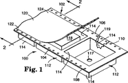
図1は、本発明のキャリアテープの部分透視図である。図中、静電消失コーティングの一部が除去され、下の構造がより明確に示されている。また、そのカバーは、部分的に除去されてキャリアテープ内に保管された部品を示している。しかしながら、ポケットの内部をより明確に示すために部品は主要なポケットからは省かれている。
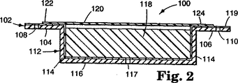
図2は図1の2−2線に沿った部分図である。
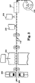
図3は本発明によるキャリアテープの一製造方法の概略図である。
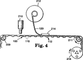
図4は本発明によるキャリアテープに部品を充填し、続いてカバーを取り付ける方法を示す概略図である。
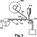
図5は本発明によるキャリアテープから部品を除去するロボット式マシンを示す概略図である。
好ましい実施形態の詳細な説明
図面を参照すると、本発明によるキャリアテープが図1および2に示されている。図示されたキャリアテープは、部品(特に電子部品)を保管し、前進メカニズムにより送出するのに有用である。より詳しくは、フレキシブルキャリアテープ100は、上面およびその上面の逆側の下面を定義するキャリアまたはストリップ部分102を有している。ストリップ部分102は、縦の端表面104および106、および端表面の一つ、好ましくは両面に、そしてそれに沿って形成された配列前進穴108および110の列を含んでいる。前進穴108および110は、キャリアテープ100を所定の位置に進める鎖歯車ドライブの歯のような前進メカニズムを受け止める手段を提供する。
一連のポケット112が、ストリップ部分102に、そしてそれに沿って間隔をあけて形成されており、ポケットは、ストリップ部分の上面へ開口している。一つのキャリアテープ内の各ポケットは通常実質的に他のポケットと同一である。通常、それらは互いに一列に等しい間隔をあけて並んでいる。図示した実施形態において、各ポケットには、4つの側壁114が含まれており、それぞれ隣接する側壁に対してほぼ直角である。側壁114は隣接しており、ストリップ部分の上面から下方に延在しており、下部壁116に隣接していてポケット112を形成している。下部壁116は、ほぼ平面でストリップ部分102の面に平行である。任意で、しかし望ましくは、下部壁116には、ポケット112に保管された部品118(電子部品のような)を除去するのを促すために、メカニカルプッシュアップ(例えば、ポークアップニードル)を収容する大きさのアパーチャまたはスルーホール117が含まれていてもよい。アパーチャ117はまた、あるポケットの中の部品の有無を検出するために光学スキャナにより用いられることもある。さらに、アパーチャ117は、ポケットに部品をより効果的に充填するために、ポケットを真空にするのにも有用である。
ポケット112は、受け止めようとする部品のサイズおよび形に合うように設計することができる。特に図示はしないが、ポケットの有する側壁は、好ましい実施形態において示された4つより多くても少なくてもかまわない。一般に、各ポケットには、隣接し、ポケットを形成するためにストリップ部分102から下方へ延在する少なくとも1つの側壁と、側壁と隣接している下部壁が含まれる。このように、ポケットの外形は、円形、楕円形、三角形、多角形またはその他の形状であってもよい。各側壁はまた、部品の挿入を促進し、キャリアテープ作製中にポケットを鋳型から取り外したりダイを形成するのを支援するために、わずかに抜き勾配(すなわち、ポケット中央から2°から12°の傾斜)を設けて形成してもよい。ポケットの深さもまた、ポケットが受け止めようとする部品によって変えることができる。さらに、特別の部品を良好に収容または支持するために、ポケットの内部に、突部、リブ、台座、バー、レール、付属物およびその他同様の構造機構を形成してもよい。図には一列のポケットを示したが、多数の部品を同時に送出するのを促すために、2列以上の配列されたポケットをストリップ部分の長片に沿って形成してもよい。一列の複数のポケットが、隣接した列の複数のポケットと横の列が配列された状態で、互いに平行に配列されるものとする。
ストリップ部分102は、保存用リールのハブで巻き取られるのに十分なゲージおよび可撓性を有する任意のポリマー材料で形成してもよい。好ましくは、ストリップ部分102は、光学的に透明である。これは、ポケットの中に保管された部品が、矩形カバー120(以下に詳しく説明する)を除去することなく目視で検査できるのに十分なほど透明であるということを意味している。ポリエステル(例えば、グリコール−変性ポリエチレンテレフタレート)、ポリカーボネート、ポリプロピレン、ポリスチレンおよびアクリロニトリル−ブタジエン−スチレンを含む様々なポリマー材料を用いることができるが、これに限られるものではない。しかしながら、その優れた透明性、低ヘーズ、良好な熱抵抗性および良好な機械特性から、ポリカーボネートの使用が特に好ましい。
利点として、ストリップ部分102には、静電消失材料119の層またはコーティングが含まれる。静電消失コーティングは、キャリアテープ全体から電荷を消失させて、好ましくは接地させることができる。この特徴が、蓄積された静電電荷により、キャリアテープ内に含まれるコーティングが損傷されるのを防ぐのを助ける。静電消失コーティング119を、ポケット側壁114およびポケット下部壁の内部表面、すなわち、ポケット112により搬送される部品に面する面に付ける。静電消失コーティング119はまた、ストリップ部分102の縦の端表面104および106に付けてもよい(付けるのが好ましい)。静電消失コーティング119はまた、ストリップ部分102の下面(すなわち、ポケット側壁および下部壁の外表面)に付けてもよい。コーティングはまた、触ったときに乾燥(すなわち非粘着性)していなければならない。
静電消失コーティング119は、静電消失材料により提供される。本発明に有用なこれらの材料は、ポリマー界面活性剤であるといえる。特に好ましい例としては、アルキルアクリレート(例えば、ブチルアクリレート)、アルキルメタクリレート(例えば、メチルメタクリレート)およびトリアルキルアンモニウムハライドアルキルメタクリレート(例えば、2−(塩化トリメチルアンモニウム)エチルメタクリレート)のポリマー(すなわち、ターポリマー)が挙げられる。非常に有用な市販の材料は、ガラス転移温度が200℃で、23℃そして65%の相対湿度の表面抵抗率が約109オーム/平方であるNippon Nyukazi Co., Ltd.(日本)製のRS−811である。
静電消失材料は、キャリアに塗布しやすい溶液の形態で提供されるのが一般的である。溶液を形成するための溶媒は、静電消失材料が溶解する、または乳化できるものでなければならない。溶媒はまた、ストリップ部分を濡らすものでなければならない。水/メタノール溶媒系を用いてもよいが、水/エタノール溶媒系が特に好ましく、有用な例としては約80〜95%のエタノール、これに対応して約20〜5%の水を含有したものである。静電消失効果となるように、好ましくは約1.0〜3.0wt%の静電消失材料、より好ましくは約1.2〜2.0wt%の静電消失材料を溶媒に加える。乾燥すると、静電消失材料層は、好ましくは約0.1〜1.0μmの厚さ、より好ましくは約0.2〜0.4μmの厚さである。
単体キャリアテープ100にはまた、矩形カバー120(カバーテープと呼ばれることもある)が含まれる。カバー120は、コーティングを保持するためにキャリアテープのポケットを覆うように取り付けられる。カバー120はまた、ポケットに侵入する埃およびその他汚染物質から部品を保護することができる。図1および2によく示されているように、カバー120は可撓性があり、ポケット112の全ての部分を覆い、ストリップ部分102の長さに沿って前進穴108および110の横の列の間に配置されている。カバー120は、ストリップ部分102の上面に取り外し可能に固定されており、後に除去して、保管された部品に到達できるようにする。図示したように、カバー120には、それぞれ、ストリップ部分102の縦の端表面104および106に接合された平行な縦の接合部分122および124が含まれている。例えば、アクリレート材料のような感圧接着剤、またはエチレン−酢酸ビニルコポリマーまたはスチレン−ブタジエンブロックコポリマーのような熱活性接着剤を用いてカバーを端表面104および106に接着する。接着剤の厚さは、通常、約30μmである。ストリップ部分を良好にシールするためには、熱活性接着剤を用いるのが特に好ましい。カバーは、接着層をカバーに接着するのを促進するために下塗りしてもよい。カバー120は、ストリップ部分に目視で確認できる接着剤またはその他の種類の残渣を残すことなくストリップ部分102から除去されるのが好ましい。このような残渣は、埃またはその他汚染物質を引き寄せ、キャリアをリサイクルして再使用するのを難しくする。
完全に静電消失したキャリアテープを提供するために、カバー120は、静電消失するよう変性しなければならない。カバー120は、ポリマー材料中に点在するか、または後にカバーにコーティングされるカーボンブラック、五酸化バナジウムまたは界面活性剤のような静電消失材料を含んでいてもよい。静電消失材料はまた、接着に悪影響を及ぼさない限りは、カバー120をストリップ部分102に接合する接着剤に組み込んでもよい。ストリップ部分102で述べた通り、カバーは光学的に透明であるのが望ましい。カバー120は、ストリップ部分102を提供するのに用いられるようなものを含む様々なポリマー材料で形成してよい。ポリエステル類(特に、ポリエステル類ベースのポリエチレンテレフタレート)が特に好ましい。有用な、市販されている静電消失カバーテープとしては、DENKA ALS-AS(Denki Kagaku Kogyo Co. Ltd.,日本)が例示される。カバーの厚さ(接着剤は含まない)は通常約25μmである。
一般に、本発明のキャリアテープは、ポリマー材料のシートにポケットを形成し、キャリアテープをリール上に巻き付けてロールを形成することにより作製される。特に、図3の概略図を例として参照すると、フレキシブル熱可塑性ポリマーのフィルム状材料(web)200を事前形成ロール、事前形成されたシートとして、直接押出し、または連続注入成形により、フィルム状材料を熱成形する鋳型またはダイ204(適合する一対の雄雌ダイ)へ供給する。鋳型204は、ポケットを所望のサイズおよび形状に熱成形する(冷却の際、後に収縮可能)。入ってくるポリマーフィルム状材料の寸法は、形成されるキャリアテープのゲージおよび幅により決められる。
「熱成形」とは、熱と圧力の両方を用いて熱可塑性材料を変形するプロセスのことを言う。熱は鋳型そのもの、予熱器202または押出し機(特に図示せず)により与えてもよい。いずれにしても、ポリマーフィルム状材料200は熱成形できるくらいに十分加熱する。ポリマーフィルム状材料を加熱しなければならない温度は、熱成形される材料のゲージおよびタイプ、そして製造ラインの速度によって広い範囲にわたって異なる(すなわち、約200〜550°F)。印加された圧力は、鋳型またはダイパターンの高品質な複製となるくらい十分なものとし、例えば、鋳型を閉じるときに鋳型がフィルム状材料200上にかける力、またはフィルム状材料を雄ダイの上で変形させて、フィルム状材料を雌ダイへ引き抜くのを促す真空塗布(すなわち、真空熱成形)することにより提供してもよい。フィルム状材料200は、熱成形の後、通常、空冷、ファン、水浴または冷却オーブンにより熱可塑性ポリマーが固化するまで冷却される。
一般に、熱形成は、当業者に良く知られたプロセスであり、異なる熱成形プロセスおよびロール供給、シート供給、インライン押出しおよび連続フィルム状材料システムの使用について論じているEncyclopedia of Polymer Science and Engineering(Jone Wiley & Sons, 1989年、第16巻、第2版)のような様々な参照文献に記載されている。適合する鋳型成形、プラグ−アシスト成形、基本真空成形および圧力成形のような様々な熱成形技法に用いることのできる、技術文献に記載されているフラットフォーミングおよびロータリデバイスのような異なる熱成形ツールをすべて用いて本発明のキャリアテープを製造することができる。
前進穴は、パンチ205による穿孔のような別の操作で後に形成される。
キャリアが準備できたら、静電消失コーティングを、浸漬、ブラッシングまたはスプレー(例えば、空気スプレーまたは超音波スプレー)(図3にステーション206として概略図が示されている)を含む様々な技法により塗布する。静電消失コーティングを塗布したら、フィルム状材料上にドライコーティングを形成するために、コーティングしたフィルム状材料200は、溶媒またはキャリア液体が蒸発するのに十分な温度および時間、乾燥させなければならない。これは、コーティングしたフィルム状材料を乾燥オーブン207を通過させることで容易に行うことができる。
キャリアテープをリール208の芯の周りに巻き付けて(同心または水平巻き付けのいずれか)、キャリアテープに部品が充填されるまで保管するための供給ロールを形成する。この代わりに、図4に示すように、キャリアテープ100を形成した直後に、部品装填機210がポケット112に部品118を充填し、カバー120をロール212から送出し、アプリケーター214によりキャリアテープストリップ部分の縦の端表面へ固定して、充填したキャリアテープを芯またはリール216の周りに保管または送出のために巻き付ける。熱活性接合を提供するカバーの場合、アプリケーターを加熱する。好ましくは、接合は、室温(約25℃)と約220℃の間、より好ましくは室温と約200℃の間、最も好ましくは室温と約180℃の間の温度で形成する。キャリアテープ100を鎖歯車209および211により進める。
使用に際しては、ロボット式配置マシン218と共にキャリアテープ100が図示された図5の概略図に示すように、キャリアテープを外す。サプライリール216はキャリアテープ100を供給する。剥離機アセンブリ220は、剥離機アセンブリが指定した経路をはずれてキャリアテープを引っ張るのを防ぐ支援をする剥離機ブロック222の周りのキャリアテープ100からカバー120を剥離する。キャリアテープ100を鎖歯車224により進めて、キャリアテープをロボット式配置マシン218へ移動する。各部品が順次所望のピックアップポイントに到達したら、ロボット式配置マシンが、部品を掴み(手または吸い込むかのいずれかにより)、例えば、適切な位置の回路基板上に配置する。
本発明のキャリアテープは、メモリチップ、集積回路チップ、抵抗器、コネクタ、デュアル・インラインプロセッサ、コンデンサ、ゲートアレイ等のような表面実装電子部品を搬送および送出するために、電子業界において特に有用である。しかしながら、キャリアテープは、小さなスプリング、クリップ等の他の部品を搬送するのに用いてもよい。
本発明は、以下の実施例を参照するとより完全に理解されよう。ただし、これに限られるものではない。
全般的な前処理
静電消失材料の水/アルコール溶液を、部品ポケットを有するストリップ部分に塗布し、溶媒を除去することによって静電消失ストリップ部分を作成した。より詳しく述べると、水:エタノール(1:10w/w)溶媒混合物中に1.5固体重量%のRS−811ターポリマー(Nippon Nyukazai Company, Ltd.,日本)を含む溶液を、幅8ミリメートル(mm)および厚さ0.25mmのポリカーボネートフィルム状材料(3Mブランド#2703、3M Company, St. Paul, ミネソタ州)にスプレーコーティングして、65℃で2分間乾燥させて静電消失ストリップ部分を作成した。(水/エタノール混合物を作成するのに用いた水は、最初にイオン交換により精製した。)乾燥したコーティングの厚さは約0.3μm(ミクロン)と計算された。
熱および圧力を用いてカバーテープでストリップ部分をシールして、キャリアテープを形成した。より詳しく述べると、静電消失の、接着剤をコーティングしたカバーテープ、DENKA ALS-AS(Denki Kagaku Kogyo Co., Ltd.,日本)を、圧力10psi、2.5走向、走行毎の休止時間0.4秒および温度180℃の往復モード(走行毎のキャリアテープのインデクシングは32mm)で作動させたMT-30テーパー(Systemation Engineered Products, Inc., New Berlin,ウィスコンシン州)を用いてストリップ部分に接着した。
試験方法
表面抵抗率
「全般的な前処理」で記載した通りに作成されたストリップ部分の静電消失特性を、表面抵抗率を測定することによって評価した。より詳しく述べると、表面抵抗率は、20mm離れた位置にある2つのピン(直径=2mm)を有する2ピンプロープ(40x30x42mm)(Hiresta series probe、タイプHA、モデル#MCP-HTP1、Mitsubishi Chemical Corp.,(日本))を用いた以外は、日本工業規格試験方法JIS-K-6911により測定した。印加した圧力は500ボルトであった。ストリップ部分は長さ500ミリメートルで、10回の測定ができた。試料を2〜4時間23℃で相対湿度(RH)65%の状態にして、23℃、65%RHで試験した。1E10オーム/平方未満の表面抵抗率であるのが望ましく、3E9オーム/平方未満の値であるのが好ましい。
透明度およびヘーズ
「全般的な前処理」で記載した通りに作成されたストリップ部分の透明度およびヘーズを評価して、後に付けたカバーテープを除去しない目視検査手順に対する適合性を判定した。より詳しく述べると、透明度およびヘーズは、日本工業規格試験方法JIS-K-7105(1981年3月1日発行)を用いて測定した。85%を超える値の透明度が望ましく、90%を超える値であるのが好ましい。5%未満のヘーズ値が望ましく、1%未満の値であるのが好ましい。
静電蓄積
キャリアテープの静電荷蓄積に対する感受性を評価した。より詳しく述べると、ストリップ部分に100個のセラミックコンデンサチップ(0.16mmx0.08mm)をポケット当たり1個のチップずつ充填し、「全般的な前処理」で記載した通りDENKA ALS-ASカバーテープでシールした。充填およびシールされたキャリアテープを振とう機に入れて、23℃、65%RHで200/分の周波数で70時間振とう(振動距離=40mm一方向)した。70時間後、キャリアテープを振とう機から取り出し、逆さまにして、カバーテープをゆっくり注意して手で剥がした。静電荷の蓄積によりストリップ部分のポケットに残ったチップの数を数えた。残ったチップの数は、1000個当たり1個未満(0.1%未満)でなければならない。
剥離接着力
カバーテープをストリップ部分から剥がすのに必要な力を、日本工業規格試験方法JIS-C-0806(1990年1月1日発行)を用いて測定した。カバーをストリップ部分から300ミリメートル/分の連続剥離速度で180°の角度で剥がした。5つの試料を試験し、その結果を用いて、平均剥離接着力を計算した。一般に、10〜70グラム重の剥離接着力が望ましく、20〜60グラム重であるのが好ましい。カバーテープは均等に除去しなければならない。音を立てて剥がす(接着の強い、または弱い領域)のは望ましくない。カバーテープはまた、ストリップ部分に目視で見える接着剤残渣を残すことなく除去しなければならない。
エージング
いくつかの試料の表面抵抗率、剥離接着力および静電蓄積の特性をまた、様々なエージングプロトコルの後に測定した。エージングプロトコルには、次の条件の1つまたはそれ以上が含まれていた。A)23℃でのエージング、B)40℃でのエージング、C)60℃でのエージング、D)40℃/80%RHでのエージングおよびE)50℃/95%RHでのエージング。表面抵抗率の測定には、電子部品およびカバーテープのないストリップ部分をエージングさせて上述の通りに試験した。剥離接着力の測定には、カバーテープでシールしたストリップ部分をエージングさせて上述の通りに試験した。静電蓄積測定には、電子部品およびカバーテープのないストリップ部分をエージングさせて電子チップを充填した。その後カバーテープをストリップ部分にシールした。充填され、シールされたキャリアテープを上述の通りに試験した。
表面抵抗率について好ましい(およびより好ましい)値は、次の通りである。コンディションAで1000時間か、コンディションCで100時間の場合:1E11オーム/平方未満(3E10オーム/平方未満)、コンディションDで200時間の場合:3E11オーム/平方未満(1E11オーム/平方未満)。
剥離接着力について好ましい(およびより好ましい)値は、次の通りである。コンディションAで1000時間の場合:10〜70グラム重(20〜60グラム重)、コンディションCで1000時間の場合:10〜80グラム重(20〜70グラム重)およびコンディションDで200時間の場合:10〜70グラム重(20〜60グラム重)。
実施例1
「全般的な前処理」で上述した通りに静電消失ストリップ部分を作成した。初期および様々なエージングプロトコル後の表面抵抗率、および初期の透明度とヘーズについて、上述した通りにストリップ部分を試験した。結果を表1に示す。
比較例1
比較例(C.E.)1において、静電消失コーティングを用いなかった以外は実施例1のストリップ部分を作成した。ストリップ部分を上述の実施例1と同様に試験した。結果を表1に示す。
比較例2
比較例2を作成するために、比較例1のストリップ部分を、5固体重量%までメチルエチルケトンで希釈した酸化錫(ELCOM P-3537、メチルエチルケトン中の25固体重量%、Shokubaikasei Kogyo Company, Ltd.,日本)の分散液でスプレーコーティングし、65℃で2分間乾燥させて、約0.2μmの計算厚さとした。初期および様々なエージングプロトコル後の表面抵抗率、および初期の透明度とヘーズについてストリップ部分を試験した。結果を表1に示す。
比較例3
比較例1のストリップ部分を、4固体重量%まで1:1水:エタノール混合物で希釈したアルキルスルホン酸ナトリウム(ATRAIT AS-140、水中の40固体重量%、Nikko Petrochemicals Company, Ltd.,日本)でスプレーコーティングし、65℃で2分間乾燥させ、約0.7μmの計算厚さとして、比較例3を作成した。初期および様々なエージングプロトコル後の表面抵抗率、および初期の透明度とヘーズについてストリップ部分を試験した。結果を表1に示す。

実施例2
本発明による静電消失キャリアテープを、実施例1の静電消失ストリップ部分および「全般的な前処理」で記載したDENKA ALS-ASカバーテープを用いて作成した。実施例2の静電蓄積について上述の通りに試験した。結果を表2に示す。
比較例4
比較例1のストリップ部分およびカバーテープのシーリング温度を220℃とした以外は、実施例2に記載した通りに比較例4を作成し、試験した。結果を表2に示す。
比較例5
比較例2のストリップ部分およびカバーテープのシーリング温度を220℃とした以外は、実施例2に記載した通りに比較例5を作成し、試験した。結果を表2に示す。
比較例6
比較例3のストリップ部分およびカバーテープのシーリング温度を220℃とした以外は、実施例2に記載した通りに比較例6を作成し、試験した。結果を表2に示す。
実施例3
カバーテープのシーリング温度を190℃とした以外は実施例2に記載した通りに本発明の静電消失キャリアテープを作成した。初期および様々なエージングプロトコル後の剥離接着力について、実施例3を上述の通りに試験した。結果を表3に示す。
実施例4
DENKA ALS-ASカバーテープではなく、3Mブランドの導電性感圧カバーテープ#2666を23℃および10psiの圧力で用いた以外は、実施例2に記載した通りに本発明の静電消失キャリアテープを作成した。初期および様々なエージングプロトコル後の剥離接着力について、実施例4を上述の通りに試験した。結果を表3に示す。
表3には比較例4〜6も併記してある。
実施例5
異なるシーリング温度を用いた以外は、実施例2に記載した通りに、本発明の一連の静電消失キャリアテープを作成した。実施例5の剥離接着力を上述した手順を用いて23℃で試験した。結果を表4に示す。
比較例7
異なるシーリング温度を用いた以外は、比較例4に記載した通りに、一連のキャリアテープを作成した。比較例4の剥離接着力を上述した手順を用いて23℃で試験した。結果を表4に示す。
本発明は、カバーテープとキャリアの間の接合を促進すると同時に、意外にもキャリアの静電を消失させるものであった。このように、本発明は、驚いたことに、低いシーリング温度を用いてカバーテープを静電消失ポリカーボネートキャリアに接合させることを可能にするものである。低いシーリング温度は、カバーテープまたはキャリアの変形の恐れを減じ、製造コストを下げ、安全であるために有利である。さらに、キャリアの幅が増えるに従い、カバーがシールされる温度は通常増大する。しかしながら、高いシーリング温度が既に狭い幅のキャリアに必要とされている場合は、より広い幅を作製するのは難しいこともある。
本発明を、いくつかの実施例により説明してきた。本発明の範囲から逸脱することなく、当業者であれば、記載した実施例を様々に変更することができることは明白であろう。従って、本発明の範囲は、ここに記載した構造に限定されず、請求項の文言およびこれら構造の均等物によよってのみ限定されるものとする。 Background of the Invention
Technical field
The present invention relates generally to a carrier tape for storing electronic components and sequentially supplying these components to a machine. In particular, the present invention relates to a carrier tape having electrostatic dissipation characteristics.
Description of prior art
In general, carrier tapes used to transport parts to different parts manufacturers that assemble into new products are well known. For example, in the field of electronic circuit assemblies, electronic components are transported from a supply of such components to a specific location on the circuit board to which they are attached. There are several different types of components including surface mount components. For example, a memory chip, an integrated circuit chip, a resistor, a connector, a dual in-line processor, a capacitor, a gate array, etc. are specifically exemplified. Such components are typically attached to circuit boards that are later incorporated into electronic devices.
Robotic placement machines, sometimes known as “pick-and-place” machines, are widely used in the electronics industry, rather than attaching individual electronic components to the circuit board by hand. Yes. In this method, a part on a specific position (supply) side is grasped and arranged on the other specific position (circuit board) side. In order to ensure sustained operation of the robotic placement machine, the machine must be equipped with a continuous supply of electronic components.
One method for continuously supplying electronic components to a desired position is to use a carrier tape. Conventional carrier tapes usually comprise a rectangular plastic strip (often called a carrier). The plastic strip has a series of identical pockets formed along the elongated piece at predetermined and equally spaced intervals. The pocket is designed to receive electronic components. A continuous cover (often called cover tape) is attached over the rectangular strip to hold the parts in the pocket. The carrier tape is supplied to a robotic placement machine. The machine pulls the continuous cover tape away from the carrier, removes the parts from the pockets, and places them on the circuit board.
Due to vibrations that occur during the transport of the carrier tape, the stored parts come into contact with the cover tape and / or the wall of the pocket. Static electricity is generated by the resulting friction. Static electricity is generated even if the cover tape is removed. Unfortunately, just the electrostatic field and the subsequent electrostatic discharge can be very detrimental to sensitive electronic components. This is especially true for modern semiconductors and integrated circuits that can be degraded or destroyed by the occurrence of static electricity on the workpiece. Particularly sensitive parts are greatly affected by a small potential of 50 volts, but by simply walking, a potential of 30,000 volts or more is generated by triboelectricity.
Various techniques have been developed in an attempt to address this problem. For example, carbon black, metal oxides and other antistatic agents have been incorporated into the polymer resin from which the carrier is formed. Some of these materials reduce carrier transparency. However, it is often desirable for the carrier to be transparent so that stored parts can be visually inspected without removing the cover tape. The incorporated antistatic agent functions by migrating, blooming or breathing to the surface. However, the effects of these substances diminish over time.
Another technique that has been developed is to apply an electrostatic dissipation coating to the carrier or cover tape. For example, JP-A-4-214339 discloses a transparent conductive coating for a carrier. This coating comprises tin antimony oxide in a vinyl chloride-vinyl acetate copolymer resin and an acrylic resin based binder resin. Plastics used to make the carrier are polystyrene, polyvinyl chloride and polyethylene. The carrier may be used with a base tape that includes polyester, a cover tape that includes a heat seal resin layer that includes an antistatic agent such as an ethylene-vinyl acetate copolymer resin and a nonionic surfactant. The presence of the tin oxide compound increases haze and adversely affects the ability to bond well between the cover tape and the carrier.
JP-A-5-42969 discloses 7, 7, 8, 8 dispersed in an acrylic binder to provide a transparent conductive coating for a plastic carrier tape base sheet (eg, vinyl chloride, polystyrene or polyethylene). -Tetracyanoquinodimethane conductive fillers are disclosed.
In order for the electrostatic dissipation cover tape to be most effective, an electrostatic dissipation coating must be applied to the inner surface, ie, the surface facing the interior of the component transport pocket. This surface is usually provided with an adhesive for adhesive bonding with the carrier. U.S. Pat. No. 4,902,573 (Jonas et al.) Notes that adhesion loss occurs when an antistatic material is placed in the adhesive. Jonas et al. Further state that adhesives are often thermally active and that the heat used to join the carrier can lower the charging characteristics.
According to Jonas et al., "Plastic films that have traditionally had an adhesive thermoplastic coating have not been electrified, because the adhesive thermoplastic coating has lost its adhesion due to the electrification finish. In addition, if the adhesiveness is not lost due to the temperature normally used for heat sealing (melting), it is conventionally used for the electrification finishing of plastics. From the experience of long-term chargeable thermal stability, a charged finish is expected, but it is still severely reduced. "Jonas et al. Oxidize binders and 5- or 6-membered heterocyclic compounds. We propose to coat the adhesive with a solution containing an oxidizer for polymerization and to treat the resulting coating with a solution of a heterocyclic compound. ing. However, the presence of heteroatoms will undesirably change the color of the cover tape over time.
US Pat. No. 5,208,103 (Miyamoto et al.) Mentions similar concerns and further notes that it is difficult to select a binder that will stably bond to the carrier. According to Miyamoto et al., “Antistatic treatment for the inner surface of the cover tape, ie the adhesive layer of the cover tape, is done by coating or incorporating an antistatic agent into the adhesive layer. The antistatic agent incorporated in the adhesive layer bleeds to the inner surface of the cover tape, causing unstable sealing and a lot of trouble due to poor sealing. However, it is greatly affected by the temperature and humidity using the package, particularly the humidity conditions, and greatly decreases at a low humidity such as 10% RH. The conductive material is incorporated into the adhesive layer because the adhesive layer is formed by laminating an extruded film or the like on the outer layer. In addition, the transparency of the resulting cover tape is greatly reduced by the incorporation, and the usefulness of the cover tape is questioned.The coating on the adhesive layer of conductive material can be stably bonded to the carrier tape. It is difficult to select the correct binder, and the adhesive layer is covered and hidden by the coating, which is not practical in practice. "
Miyamoto et al. Discloses a multilayer cover tape in which a biaxially oriented polyester, polypropylene or nylon layer is adhesively bonded to a polyolefin interlayer. The reverse surface of the polyolefin layer is coated with a transparent, thermoplastic, heat sealing adhesive layer, filled with conductive particles, bonded to a carrier. When the cover tape is removed from the carrier, the agglomeration of the polyolefin intermediate layer is impaired and a portion thereof remains adhesively bonded to the carrier. Residues left on the carrier attract dust and other contaminants, making it difficult to recycle and reuse the carrier.
Thus, there has been a need for a carrier tape that includes an electrostatic loss carrier and an adhesive bonded cover tape that is preferably also static loss. If the carrier contains an electrostatic dissipation coating, adhesion to the cover tape should not be reduced or impaired. Ideally, the electrostatic dissipation coating promotes adhesion to the cover tape, allowing the cover tape to adhere firmly to the carrier without significant changes in adhesion over time, and lowering the heat-bondable cover tape. Allow adhesion to the carrier at temperature. If the adhesive force decreases over time, the cover tape will loosen and the stored parts will be lost early. As the adhesive force increases over time, it becomes difficult to remove the cover tape from the carrier. Similarly, the static dissipation characteristics should not be significantly lost over time and under normal manufacturing and storage conditions. The overall structure must also remain sufficiently transparent so that the electronic components carried by the carrier tape are visible without the cover tape being removed.
Summary of the Invention
The present invention relates to a flexible carrier tape for electronic component storage and delivery by an advance mechanism. The carrier tape includes an electrostatic dissipative strip portion having an upper surface, a lower surface opposite the upper surface, and a plurality of pockets arranged to transport the parts, the pockets being spaced along the strip portion. They are arranged and open to the upper surface.
The pocket generally includes at least one side wall adjacent and extending downward from the strip and a lower wall adjacent to the side wall. More preferably, the pocket includes four sidewalls each approximately perpendicular to the adjacent sidewall. Typically, the pockets are substantially identical and are aligned at equal intervals along the strip portion. The strip portion further has first and second parallel longitudinal end surfaces, and at least one of the end surfaces is aligned with a plurality of equally spaced spaces that receive the advancement mechanism (eg, chain gear). Preferably, holes are included.
The strip portion further includes a static-dissipating material having a static-dissipating effect thereon. Electrostatic dissipation materials include polymers of alkyl acrylate (preferably butyl acrylate), alkyl methacrylate (preferably methyl methacrylate) and trialkylammonium halide alkyl methacrylate (preferably 2- (trimethylammonium chloride) ethyl methacrylate) (ie, tar Polymer).
The carrier tape also includes a cover (preferably electrostatic dissipative) that is peelably adhesively bonded to the top surface of the strip portion, extends along the strip portion, and covers the pocket.
In a preferred embodiment, the strip portion is formed from polycarbonate, the cover is formed from polyester, and the adhesive joining the cover to the strip portion is a thermally bondable material such as an ethylene-vinyl acetate copolymer or a styrene-butadiene block copolymer. It is.
The static elimination coating used on the strip portion does not adversely affect the adhesion to the cover even under very active conditions of high temperature and humidity. Very surprisingly and surprisingly, the static-dissipating material promotes adhesion to the actually heat-bondable cover so that no static-dissipating coating is present or other static Such a cover can be joined to the strip portion at a temperature below that which can be used if an electro-dissipating material is used. Even with the electrostatic dissipation coating, the carrier tape remains transparent to the extent that visual inspection of the parts conveyed by the carrier tape without removing the cover is possible.
Thus, the present invention also relates to a method for reducing the temperature at which a heat bondable cover is bonded to a polycarbonate carrier by using an acrylic polymer layer in the strip portion. The present invention further provides a method of using an acrylic polymer to dissipate static electricity in the strip portion of the polycarbonate carrier tape and to reduce the temperature at which the strip portion can be thermally bonded to a cover having a thermally bondable adhesive. About.
[Brief description of the drawings]
The invention will be more fully understood with reference to the following drawings. Similar or similar parts are provided with the same reference numerals.
FIG. 1 is a partial perspective view of the carrier tape of the present invention. In the figure, a portion of the electrostatic dissipation coating has been removed to show the underlying structure more clearly. The cover also shows parts that have been partially removed and stored in the carrier tape. However, parts have been omitted from the main pocket to more clearly show the interior of the pocket.
FIG. 2 is a partial view taken along line 2-2 of FIG.
FIG. 3 is a schematic view of one method for producing a carrier tape according to the present invention.
FIG. 4 is a schematic view showing a method of filling a carrier tape according to the present invention with components and subsequently attaching a cover.
FIG. 5 is a schematic diagram showing a robotic machine for removing parts from a carrier tape according to the present invention.
Detailed Description of the Preferred Embodiment
Referring to the drawings, a carrier tape according to the present invention is shown in FIGS. The illustrated carrier tape is useful for storing parts (particularly electronic parts) and delivering them by an advance mechanism. More particularly, the
A series of
The
The
Advantageously, the
The
The electrostatic elimination material is generally provided in the form of a solution that is easy to apply to a carrier. The solvent for forming the solution must be one that can dissolve or emulsify the static-dissipating material. The solvent must also wet the strip portion. A water / methanol solvent system may be used, but a water / ethanol solvent system is particularly preferred, with useful examples containing about 80-95% ethanol, correspondingly about 20-5% water. It is. Preferably, about 1.0 to 3.0 wt% of the static disappearance material, more preferably about 1.2 to 2.0 wt% of the static dissipation material is added to the solvent to provide an electrostatic dissipation effect. When dried, the static dissipation material layer is preferably about 0.1 to 1.0 [mu] m thick, more preferably about 0.2 to 0.4 [mu] m thick.
The
In order to provide a completely static-dissipated carrier tape, the
Generally, the carrier tape of the present invention is produced by forming a pocket in a sheet of polymer material and winding the carrier tape on a reel to form a roll. In particular, referring to the schematic diagram of FIG. 3 as an example, a film material (web) 200 of a flexible thermoplastic polymer is formed into a film-like material by direct extrusion or continuous injection molding as a pre-formed roll, a pre-formed sheet. Feed into a mold or die 204 (a pair of matching male and female dies) to be thermoformed. The
“Thermoforming” refers to the process of deforming a thermoplastic material using both heat and pressure. Heat may be applied by the mold itself, the
In general, thermoforming is a process well known to those of ordinary skill in the art, and the Encyclopedia of Polymer Science and Engineering (Jone) discussing different thermoforming processes and the use of roll feeding, sheet feeding, in-line extrusion and continuous film-like material systems. Wiley & Sons, 1989, Vol. 16, 2nd edition). Different thermoforming tools such as flat forming and rotary devices described in the technical literature, which can be used for various thermoforming techniques such as suitable mold forming, plug-assist forming, basic vacuum forming and pressure forming All can be used to produce the carrier tape of the present invention.
The advance hole is formed later by another operation such as drilling by the
Once the carrier is ready, the electrostatic dissipation coating is applied by a variety of techniques including dipping, brushing or spraying (eg, air spray or ultrasonic spray) (shown schematically as
The carrier tape is wrapped around the core of the reel 208 (either concentric or horizontal) to form a supply roll for storage until the carrier tape is filled with parts. Instead, as shown in FIG. 4, immediately after the
In use, the carrier tape is removed as shown in the schematic diagram of FIG. 5 with the
The carrier tape of the present invention is particularly useful in the electronics industry for transporting and delivering surface mount electronic components such as memory chips, integrated circuit chips, resistors, connectors, dual in-line processors, capacitors, gate arrays, and the like. is there. However, the carrier tape may be used to transport other parts such as small springs, clips and the like.
The invention will be more fully understood with reference to the following examples. However, the present invention is not limited to this.
General preprocessing
A static / dissipative strip portion was created by applying a water / alcohol solution of the static extinguishing material to the strip portion having the part pocket and removing the solvent. More specifically, a solution containing 1.5% solids by weight RS-811 terpolymer (Nippon Nyukazai Company, Ltd., Japan) in a water: ethanol (1:10 w / w) solvent mixture was prepared at a width of 8 millimeters ( mm) and 0.25 mm thick polycarbonate film-like material (3M brand # 2703, 3M Company, St. Paul, MN) and dried at 65 ° C. for 2 minutes to produce a static-dissipating strip portion did. (The water used to make the water / ethanol mixture was first purified by ion exchange.) The dry coating thickness was calculated to be about 0.3 μm (microns).
The strip portion was sealed with cover tape using heat and pressure to form a carrier tape. More specifically, a static-dissipative, adhesive-coated cover tape, DENKA ALS-AS (Denki Kagaku Kogyo Co., Ltd., Japan) with a pressure of 10 psi, 2.5 strikes, and no downtime per run Bonded to strip using MT-30 taper (Systemation Engineered Products, Inc., New Berlin, Wisconsin) operated in 4 seconds and 180 ° C reciprocating mode (32 mm carrier tape indexing per run) did.
Test method
Surface resistivity
The static dissipation properties of the strips prepared as described in “General Pretreatment” were evaluated by measuring the surface resistivity. More specifically, the surface resistivity is a two-pin probe (40 × 30 × 42 mm) with two pins (diameter = 2 mm) located 20 mm apart (Hiresta series probe, type HA, model # MCP-HTP1, Mitsubishi Chemical Corp., (Japan)) was used according to Japanese Industrial Standard test method JIS-K-6911. The applied pressure was 500 volts. The strip portion was 500 millimeters long and 10 measurements could be made. Samples were tested at 23 ° C. and 65% RH for 2-4 hours at 23 ° C. and 65% relative humidity (RH). Desirably, the surface resistivity is less than 1E10 ohm / square, and preferably less than 3E9 ohm / square.
Transparency and haze
The transparency and haze of the strips prepared as described in “General Pretreatment” were evaluated to determine their suitability for visual inspection procedures that did not remove the cover tape that was applied later. More specifically, the transparency and haze were measured using Japanese Industrial Standard test method JIS-K-7105 (issued on March 1, 1981). Transparency values greater than 85% are desirable, and values greater than 90% are preferred. A haze value of less than 5% is desirable and is preferably less than 1%.
Electrostatic accumulation
The sensitivity of the carrier tape to static charge accumulation was evaluated. More specifically, the strip portion is filled with 100 ceramic capacitor chips (0.16 mm x 0.08 mm), one chip per pocket, and with DENKA ALS-AS cover tape as described in "General Pretreatment". Sealed. The filled and sealed carrier tape was put in a shaker and shaken at 23 ° C. and 65% RH at a frequency of 200 / min for 70 hours (vibration distance = 40 mm in one direction). After 70 hours, the carrier tape was removed from the shaker, turned upside down, and the cover tape was slowly peeled off by hand. The number of chips remaining in the pocket of the strip portion due to the accumulation of static charge was counted. The number of remaining chips must be less than 1 per 1000 (less than 0.1%).
Peel adhesion
The force required to peel the cover tape from the strip portion was measured using Japanese Industrial Standard test method JIS-C-0806 (issued on January 1, 1990). The cover was peeled from the strip portion at a 180 ° angle with a continuous peel rate of 300 mm / min. Five samples were tested and the results were used to calculate the average peel adhesion. Generally, a peel adhesion of 10 to 70 grams weight is desirable and preferably 20 to 60 grams weight. Cover tape must be removed evenly. It is not desirable to make a noise and peel off (regions with strong or weak adhesion). The cover tape must also be removed without leaving a visible adhesive residue on the strip portion.
aging
The surface resistivity, peel adhesion and electrostatic build-up characteristics of some samples were also measured after various aging protocols. The aging protocol included one or more of the following conditions: A) Aging at 23 ° C. B) Aging at 40 ° C. C) Aging at 60 ° C. D) Aging at 40 ° C./80% RH and E) Aging at 50 ° C./95% RH. For surface resistivity measurements, the strips without electronic components and cover tape were aged and tested as described above. For measurement of peel adhesion, the strips sealed with cover tape were aged and tested as described above. For electrostatic accumulation measurement, the electronic chip was filled by aging the strip part without the electronic component and the cover tape. Thereafter, the cover tape was sealed to the strip portion. Filled and sealed carrier tape was tested as described above.
Preferred (and more preferred) values for surface resistivity are as follows. For condition A 1000 hours or
Preferred (and more preferred) values for peel adhesion are as follows. For condition A at 1000 hours: 10-70 gram weight (20-60 gram weight), for condition C at 1000 hours: 10-80 gram weight (20-70 gram weight) and for condition D at 200 hours: 10-70 gram weight (20-60 gram weight).
Example 1
The static elimination strip portion was made as described above in “General Pretreatment”. Strip sections were tested as described above for surface resistivity after initial and various aging protocols, and initial clarity and haze. The results are shown in Table 1.
Comparative Example 1
In Comparative Example (CE) 1, the strip portion of Example 1 was prepared except that the electrostatic dissipation coating was not used. The strip portion was tested as in Example 1 above. The results are shown in Table 1.
Comparative Example 2
To make Comparative Example 2, the strip portion of Comparative Example 1 was tin oxide diluted with methyl ethyl ketone to 5% solids by weight (ELCOM P-3537, 25% solids by weight in methyl ethyl ketone, Shokubaikasei Kogyo Company, Ltd., Japan ) And then dried at 65 ° C. for 2 minutes to a calculated thickness of about 0.2 μm. Strip sections were tested for surface resistivity after initial and various aging protocols, and initial clarity and haze. The results are shown in Table 1.
Comparative Example 3
The strip portion of Comparative Example 1 was sodium alkyl sulfonate (ATRAIT AS-140, 40% solids in water, Nikko Petrochemicals Company, Ltd., Japan) diluted with 1: 1 water: ethanol mixture to 4% solids by weight. Spray coated and dried at 65 ° C. for 2 minutes to produce Comparative Example 3 with a calculated thickness of about 0.7 μm. Strip sections were tested for surface resistivity after initial and various aging protocols, and initial clarity and haze. The results are shown in Table 1.
Example 2
An electrostatic dissipation carrier tape according to the present invention was made using the electrostatic dissipation strip portion of Example 1 and the DENKA ALS-AS cover tape described in “General Pretreatment”. The electrostatic accumulation of Example 2 was tested as described above. The results are shown in Table 2.
Comparative Example 4
Comparative Example 4 was prepared and tested as described in Example 2, except that the sealing temperature of the strip portion and cover tape of Comparative Example 1 was 220 ° C. The results are shown in Table 2.
Comparative Example 5
Comparative Example 5 was made and tested as described in Example 2 except that the sealing temperature of the strip portion and cover tape of Comparative Example 2 was 220 ° C. The results are shown in Table 2.
Comparative Example 6
Comparative Example 6 was made and tested as described in Example 2, except that the sealing temperature of the strip portion and cover tape of Comparative Example 3 was 220 ° C. The results are shown in Table 2.
Example 3
The static disappearance carrier tape of the present invention was prepared as described in Example 2 except that the sealing temperature of the cover tape was 190 ° C. Example 3 was tested as described above for peel adhesion after the initial and various aging protocols. The results are shown in Table 3.
Example 4
The static-dissipating carrier tape of the present invention was prepared as described in Example 2, except that 3M brand conductive pressure-sensitive cover tape # 2666 was used at 23 ° C. and 10 psi pressure instead of DENKA ALS-AS cover tape. did. Example 4 was tested as described above for peel adhesion after the initial and various aging protocols. The results are shown in Table 3.
Table 3 also shows Comparative Examples 4-6.
Example 5
A series of static-dissipating carrier tapes of the present invention were made as described in Example 2, except that different sealing temperatures were used. The peel adhesion of Example 5 was tested at 23 ° C. using the procedure described above. The results are shown in Table 4.
Comparative Example 7
A series of carrier tapes were prepared as described in Comparative Example 4 except that different sealing temperatures were used. The peel adhesion of Comparative Example 4 was tested at 23 ° C. using the procedure described above. The results are shown in Table 4.
The present invention unexpectedly eliminates the static electricity of the carrier at the same time as promoting the bonding between the cover tape and the carrier. Thus, the present invention surprisingly allows the cover tape to be bonded to the static-dissipating polycarbonate carrier using a low sealing temperature. A low sealing temperature is advantageous because it reduces the risk of deformation of the cover tape or carrier, lowers manufacturing costs and is safe. Furthermore, as the carrier width increases, the temperature at which the cover is sealed typically increases. However, if a high sealing temperature is already required for a narrow width carrier, it may be difficult to make a wider width.
The invention has been described by means of several examples. It will be apparent to those skilled in the art that various modifications can be made to the embodiments described without departing from the scope of the present invention. Accordingly, the scope of the invention should not be limited to the structures described herein, but only by the language of the claims and the equivalents of those structures.
Claims (5)
(b)前記ストリップ部分に沿って延在し、前記複数のポケットをカバーする、前記ストリップ部分の前記上面に剥離可能に接着接合されたカバーとを含む、電子部品を保管し、前進メカニズムによって送出するためのフレキシブルキャリアテープ。(A) an upper surface, a lower surface on the opposite side of the upper surface, a plurality of pockets for transporting electronic components that are arranged at intervals along the strip portion and open to the upper surface, and an alkyl acrylate, A static dissipative strip portion comprising a reaction product of an alkyl methacrylate and a trialkylammonium halide alkyl methacrylate, and a static dissipative material on the strip portion having an electrostatic dissipative effect;
(B) storing an electronic component including a cover extending along the strip portion and covering the plurality of pockets and releasably adhesively bonded to the upper surface of the strip portion; Flexible carrier tape to do.
(a)熱接合可能な接着剤を有するカバーを提供する工程と、
(b)前記部品を搬送するための複数のポケットを有するポリカーボネートストリップ部分と、前記カバーが前記ストリップ部分に熱接合可能となる温度を低減させるためのアルキルアクリレート、アルキルメタクリレートおよびトリアルキルアンモニウムハライドアルキルメタクリレートの反応生成物を含む材料の層とを提供する工程と、
(c)前記カバーを前記熱接合可能な接着剤で前記ストリップ部分へ熱接合する工程とを含む、
低減された温度で前記カバーを前記ストリップ部分へ接合する方法。An electronic component storage device comprising: a polycarbonate strip portion having a plurality of pockets for transporting the electronic component; and a cover that is releasably attached to the upper surface of the strip portion by a thermal bonding adhesive and covers the plurality of pockets. In a flexible carrier tape for delivery by an advance mechanism,
(A) providing a cover having a thermally bondable adhesive;
(B) a polycarbonate strip portion having a plurality of pockets for carrying the parts, and an alkyl acrylate, alkyl methacrylate and trialkylammonium halide alkyl methacrylate for reducing the temperature at which the cover can be thermally bonded to the strip portion. Providing a layer of material comprising a reaction product of:
(C) thermally bonding the cover to the strip portion with the thermally bondable adhesive;
How joining the cover to the strip portion at a reduced temperature.
Applications Claiming Priority (3)
| Application Number | Priority Date | Filing Date | Title |
|---|---|---|---|
| US08/528,684 | 1995-09-15 | ||
| US08/528,684 US5846621A (en) | 1995-09-15 | 1995-09-15 | Component carrier tape having static dissipative properties |
| PCT/US1996/013104 WO1997010693A1 (en) | 1995-09-15 | 1996-08-12 | Component carrier tape having static dissipative properties |
Publications (2)
| Publication Number | Publication Date |
|---|---|
| JPH11511418A JPH11511418A (en) | 1999-10-05 |
| JP3813633B2 true JP3813633B2 (en) | 2006-08-23 |
Family
ID=24106710
Family Applications (1)
| Application Number | Title | Priority Date | Filing Date |
|---|---|---|---|
| JP51194797A Expired - Lifetime JP3813633B2 (en) | 1995-09-15 | 1996-08-12 | Component carrier tape with electrostatic dissipation characteristics |
Country Status (9)
| Country | Link |
|---|---|
| US (1) | US5846621A (en) |
| EP (1) | EP0850552B1 (en) |
| JP (1) | JP3813633B2 (en) |
| KR (1) | KR100433641B1 (en) |
| CN (1) | CN1099225C (en) |
| DE (1) | DE69602452T2 (en) |
| IL (1) | IL123331A (en) |
| TW (1) | TW343955B (en) |
| WO (1) | WO1997010693A1 (en) |
Families Citing this family (41)
| Publication number | Priority date | Publication date | Assignee | Title |
|---|---|---|---|---|
| WO1998012908A1 (en) * | 1996-09-17 | 1998-03-26 | Matsushita Electric Industrial Co., Ltd. | Method and apparatus for packaging ic chip, and tape-shaped carrier to be used therefor |
| EP0898445A3 (en) * | 1997-08-21 | 2000-05-03 | Rexham Industries Corp. | Transparent static dissipative heat sealable cover tape |
| US6027802A (en) * | 1997-10-23 | 2000-02-22 | Four Piliars Enterprise Co., Ltd. | Cover tape for packaging |
| JP4190611B2 (en) * | 1998-03-13 | 2008-12-03 | パナソニック株式会社 | Component mounting method and component mounting apparatus |
| US6606485B1 (en) * | 1999-10-06 | 2003-08-12 | Qualcomm, Incorporated | Candidate system search and soft handoff between frequencies in a multi-carrier mobile communication system |
| AU2001241650A1 (en) * | 2000-02-25 | 2001-09-03 | Robotic Vision Systems, Inc. | Taper machine using inertial control of parts |
| JP2001297549A (en) * | 2000-04-10 | 2001-10-26 | Nitto Denko Corp | Continuous damping material supply |
| US6604876B2 (en) * | 2000-09-29 | 2003-08-12 | Zih Corp. | System for dissipating electrostatic charge in a printer |
| US20030205030A1 (en) * | 2001-02-22 | 2003-11-06 | Martin Weiss | Taper machine using inertial control of parts |
| US20030079444A1 (en) * | 2001-10-31 | 2003-05-01 | Robotic Vision Systems, Inc. | Method and apparatus for flattening cover tape |
| US6820401B2 (en) * | 2001-10-31 | 2004-11-23 | International Product Technology, Inc. | Method and apparatus for tensioning cover tape |
| SG115510A1 (en) * | 2001-12-20 | 2005-10-28 | Nitto Denko Corp | Cover tape for the electronic part conveyance, process for its production and electronic part conveying member |
| US20030198785A1 (en) * | 2002-04-23 | 2003-10-23 | Young Ha Ahn | Cover tape to be overlaid on a carrier tape for carrying parts therewith |
| JP2003341782A (en) * | 2002-05-27 | 2003-12-03 | Oki Electric Ind Co Ltd | Electronic device housing, electronic device transport method, electronic device mounting method, electronic device housing method |
| JP4317351B2 (en) * | 2002-08-23 | 2009-08-19 | 富士機械製造株式会社 | Circuit board management method and electronic circuit production system |
| DE10393438T5 (en) * | 2002-10-04 | 2005-09-08 | Electro Scientific Industries, Inc., Portland | A method of forming dimensionally accurate slits in an elastic mask of a miniature component carrier |
| US20070096345A1 (en) * | 2005-11-03 | 2007-05-03 | Vishay Vitramon Inc. | Frame packaged array electronic component |
| US20070152195A1 (en) * | 2005-12-30 | 2007-07-05 | Saint-Gobain Performance Plastics Corporation | Electrostatic dissipative composite material |
| US20070154717A1 (en) * | 2005-12-30 | 2007-07-05 | Saint-Gobain Performance Plastics Corporation | Thermally stable composite material |
| US20070154716A1 (en) * | 2005-12-30 | 2007-07-05 | Saint-Gobain Performance Plastics Corporation | Composite material |
| US20070155949A1 (en) * | 2005-12-30 | 2007-07-05 | Saint-Gobain Performance Plastics Corporation | Thermally stable composite material |
| US7476339B2 (en) * | 2006-08-18 | 2009-01-13 | Saint-Gobain Ceramics & Plastics, Inc. | Highly filled thermoplastic composites |
| KR100825491B1 (en) * | 2006-09-04 | 2008-04-25 | (주)코스탯아이앤씨 | Carrier Tape with Multi-Row Pocket |
| JP5554561B2 (en) * | 2007-04-11 | 2014-07-23 | 住友ベークライト株式会社 | Electronic parts package |
| US20080283164A1 (en) * | 2007-05-16 | 2008-11-20 | Mark Noonan | Roll-On Protective Covers for Hand-Held Consumer Electronic Devices |
| JP4460015B2 (en) * | 2007-11-09 | 2010-05-12 | シャープ株式会社 | Semiconductor device packaging structure and semiconductor device packaging method |
| WO2010065335A1 (en) * | 2008-12-03 | 2010-06-10 | 3M Innovative Properties Company | Method of making a component carrier tape |
| US8205766B2 (en) * | 2009-05-20 | 2012-06-26 | The Bergquist Company | Method for packaging thermal interface materials |
| CN103168352B (en) | 2010-08-20 | 2015-12-02 | 第一太阳能有限公司 | Tape applicator |
| JP5689001B2 (en) * | 2011-03-16 | 2015-03-25 | 富士機械製造株式会社 | Tape feeder |
| WO2013048524A1 (en) | 2011-10-01 | 2013-04-04 | Intel Corporation | Source/drain contacts for non-planar transistors |
| WO2013095527A1 (en) * | 2011-12-22 | 2013-06-27 | Intel Corporation | Electrostatic discharge compliant patterned adhesive tape |
| JP6000668B2 (en) * | 2012-06-07 | 2016-10-05 | 日東電工株式会社 | Semiconductor element marking method, semiconductor device manufacturing method, and semiconductor device |
| CN102745406A (en) * | 2012-08-03 | 2012-10-24 | 厦门市海德龙电子有限公司 | Electronic component carrier tape structure |
| JP5985073B2 (en) * | 2012-12-14 | 2016-09-06 | スリーエム イノベイティブ プロパティズ カンパニー | Adhesive composition and masking article for producing an accurate coating line |
| KR20160030135A (en) | 2013-07-09 | 2016-03-16 | 스미또모 베이크라이트 가부시키가이샤 | Cover tape for packaging electronic components |
| US9969541B2 (en) | 2016-05-14 | 2018-05-15 | Qualcomm Incorporated | Vented carrier tape |
| JP7036088B2 (en) * | 2019-06-21 | 2022-03-15 | 株式会社村田製作所 | Cover sheet adhesive strength measurement method and carrier plate |
| JP7759717B2 (en) * | 2019-11-12 | 2025-10-24 | 株式会社村田製作所 | Base tape and electronic components |
| USD1094325S1 (en) | 2021-08-24 | 2025-09-23 | Vishay Dale Electronics, Llc | Electro-magnetic device |
| CN117881609A (en) * | 2021-08-25 | 2024-04-12 | 3M创新有限公司 | Carrier tape and carrier tape assembly |
Family Cites Families (26)
| Publication number | Priority date | Publication date | Assignee | Title |
|---|---|---|---|---|
| US3324091A (en) * | 1964-03-31 | 1967-06-06 | American Cyanamid Co | Antistatic composition |
| US3517045A (en) * | 1968-06-07 | 1970-06-23 | American Cyanamid Co | Hydroxyalkyl quaternary ammonium ethers as antistatic agents |
| JPS49111949A (en) * | 1973-02-27 | 1974-10-24 | ||
| US4104175A (en) * | 1973-12-10 | 1978-08-01 | Modokemi Aktiebolag | Aqueous solutions of quaternary ammonium compounds |
| US3933779A (en) * | 1974-02-21 | 1976-01-20 | Fine Organics Inc. | Antistatic polymer blend |
| DE2960381D1 (en) * | 1978-03-15 | 1981-09-03 | Ici Plc | Antistatic films |
| US4623594A (en) * | 1984-03-12 | 1986-11-18 | Metallized Products, Inc. | Antistatic resin composition |
| CA1287322C (en) * | 1984-03-12 | 1991-08-06 | Metallized Products, Inc. | Coating and irradiating reaction product of prepolymer and antistatic quaternary ammonium salt |
| US4662154A (en) * | 1984-10-12 | 1987-05-05 | Continental Can Company, Inc. | Liquid inert gas dispenser and control |
| WO1987002333A1 (en) * | 1985-10-09 | 1987-04-23 | The Dow Chemical Company | Antistatic sheet material, package, and method of making |
| US4605684A (en) * | 1985-10-31 | 1986-08-12 | Pcolinsky Jr Michael P | Antistatic polyurethane foam |
| DE3785229T2 (en) * | 1986-01-24 | 1993-07-22 | Sumitomo Chemical Co | CLEAR, ELECTRICALLY CONDUCTIVE, PLASTICALLY-SHAPED ITEMS. |
| DE3619094A1 (en) * | 1986-06-10 | 1987-12-17 | Bayer Ag | CARBON-MOLDED MOLDED BODIES |
| DE3729875A1 (en) * | 1987-09-05 | 1989-03-23 | Bayer Ag | METHOD FOR THE ANTISTATIC FINISHING OF MELT GLUE LAYERS |
| US5171641A (en) * | 1988-01-14 | 1992-12-15 | W. R. Grace & Co.-Conn. | Permanent antistatic acid copolymer/quaternary amine polymeric films |
| US5217767A (en) * | 1988-10-28 | 1993-06-08 | Minnesota Mining And Manufacturing Company | Static shielding film |
| US5270367A (en) * | 1989-11-29 | 1993-12-14 | Denki Kagaku Kogyo Kabushiki Kaisha | Permanent antistatic resin composition |
| JPH04214339A (en) * | 1990-12-11 | 1992-08-05 | Dainippon Printing Co Ltd | Carrier tape for electronic component carriers |
| US5165985A (en) * | 1991-06-28 | 1992-11-24 | Minnesota Mining And Manufacturing Company | Method of making a flexible, transparent film for electrostatic shielding |
| MY107463A (en) * | 1991-02-28 | 1995-12-30 | Sumitomo Bakelite Co | Cover tape for packaging chip type electronic parts. |
| EP0502483A3 (en) * | 1991-03-05 | 1993-01-20 | Matsushita Electric Industrial Co., Ltd. | Static dissipative resin composition |
| JP3210685B2 (en) * | 1991-05-22 | 2001-09-17 | 触媒化成工業株式会社 | Carrier tape, conductive paint and method for producing carrier tape |
| JPH0542969A (en) * | 1991-08-09 | 1993-02-23 | Sun A Chem Ind Co Ltd | Electrically conductive carrier type |
| JP3259846B2 (en) * | 1991-10-02 | 2002-02-25 | ヤマハ株式会社 | Music signal generator |
| US5427835A (en) * | 1992-06-04 | 1995-06-27 | Minnesota Mining And Manufacturing Company | Sulfopolymer/vanadium oxide antistatic compositions |
| JP3403430B2 (en) * | 1992-08-28 | 2003-05-06 | 東ソー株式会社 | Method for producing highly conductive polymer molded article |
-
1995
- 1995-09-15 US US08/528,684 patent/US5846621A/en not_active Expired - Lifetime
-
1996
- 1996-08-12 DE DE69602452T patent/DE69602452T2/en not_active Expired - Lifetime
- 1996-08-12 EP EP96928143A patent/EP0850552B1/en not_active Expired - Lifetime
- 1996-08-12 WO PCT/US1996/013104 patent/WO1997010693A1/en not_active Ceased
- 1996-08-12 KR KR10-1998-0701936A patent/KR100433641B1/en not_active Expired - Lifetime
- 1996-08-12 CN CN96197002A patent/CN1099225C/en not_active Expired - Lifetime
- 1996-08-12 JP JP51194797A patent/JP3813633B2/en not_active Expired - Lifetime
- 1996-08-12 IL IL12333196A patent/IL123331A/en not_active IP Right Cessation
- 1996-08-19 TW TW085110110A patent/TW343955B/en active
Also Published As
| Publication number | Publication date |
|---|---|
| WO1997010693A1 (en) | 1997-03-20 |
| IL123331A (en) | 2000-11-21 |
| KR19990044681A (en) | 1999-06-25 |
| IL123331A0 (en) | 1998-09-24 |
| CN1099225C (en) | 2003-01-15 |
| US5846621A (en) | 1998-12-08 |
| EP0850552A1 (en) | 1998-07-01 |
| JPH11511418A (en) | 1999-10-05 |
| KR100433641B1 (en) | 2004-06-16 |
| TW343955B (en) | 1998-11-01 |
| DE69602452D1 (en) | 1999-06-17 |
| MX9801757A (en) | 1998-08-30 |
| DE69602452T2 (en) | 2000-01-13 |
| CN1196871A (en) | 1998-10-21 |
| EP0850552B1 (en) | 1999-05-12 |
Similar Documents
| Publication | Publication Date | Title |
|---|---|---|
| JP3813633B2 (en) | Component carrier tape with electrostatic dissipation characteristics | |
| US6030692A (en) | Cover tape for formed tape packing system and process for making same | |
| JPH09508606A (en) | Carrier tape with cover strip | |
| JP2000500720A (en) | Carrier tape with adhesive and protective wall | |
| JP2000503941A (en) | Parts carrier tape | |
| TWI389826B (en) | Cover tape and method for manufacture | |
| JP4376345B2 (en) | Cover tape for carrier tape and tape carrier | |
| TWI841722B (en) | Covering tape for packing elecronic component and package | |
| KR0174328B1 (en) | Adhesive tape | |
| MXPA98001757A (en) | Carrier ribbon of components that have distilling properties of the status | |
| JP7201125B2 (en) | Electronic component packaging cover tape and package | |
| US6875493B2 (en) | Protective cover tape having a foam layer | |
| JPH0955402A (en) | Carrier tape for semiconductor devices | |
| JP2006008152A (en) | Cover tape | |
| JPH0936182A (en) | Carrier tape for semiconductor devices | |
| JP3813214B2 (en) | Bottom material for transporting electronic components | |
| JPH06925A (en) | Carrier tape for electronic component carrier | |
| JPH0955403A (en) | Carrier tape for semiconductor devices | |
| JP3912631B2 (en) | Carrier tape | |
| JP2004106880A (en) | Cover tape for packaging electronic parts, and its manufacturing method | |
| JP4657138B2 (en) | Conductive material for packaging electronic parts and packaging container for electronic parts | |
| JP4023763B2 (en) | Conductive carrier tape | |
| JPH0924969A (en) | Carrier tape and method for manufacturing the same | |
| JPH0582884U (en) | Carrier tape for parts such as electric / electronic parts | |
| JP2001003014A (en) | Bottom cover tape for chip-type electronic component carrier |
Legal Events
| Date | Code | Title | Description |
|---|---|---|---|
| A131 | Notification of reasons for refusal |
Free format text: JAPANESE INTERMEDIATE CODE: A131 Effective date: 20060104 |
|
| A521 | Request for written amendment filed |
Free format text: JAPANESE INTERMEDIATE CODE: A523 Effective date: 20060328 |
|
| A72 | Notification of change in name of applicant |
Free format text: JAPANESE INTERMEDIATE CODE: A721 Effective date: 20060328 |
|
| TRDD | Decision of grant or rejection written | ||
| A01 | Written decision to grant a patent or to grant a registration (utility model) |
Free format text: JAPANESE INTERMEDIATE CODE: A01 Effective date: 20060523 |
|
| A61 | First payment of annual fees (during grant procedure) |
Free format text: JAPANESE INTERMEDIATE CODE: A61 Effective date: 20060601 |
|
| R150 | Certificate of patent or registration of utility model |
Free format text: JAPANESE INTERMEDIATE CODE: R150 |
|
| FPAY | Renewal fee payment (event date is renewal date of database) |
Free format text: PAYMENT UNTIL: 20090609 Year of fee payment: 3 |
|
| FPAY | Renewal fee payment (event date is renewal date of database) |
Free format text: PAYMENT UNTIL: 20100609 Year of fee payment: 4 |
|
| FPAY | Renewal fee payment (event date is renewal date of database) |
Free format text: PAYMENT UNTIL: 20110609 Year of fee payment: 5 |
|
| FPAY | Renewal fee payment (event date is renewal date of database) |
Free format text: PAYMENT UNTIL: 20110609 Year of fee payment: 5 |
|
| FPAY | Renewal fee payment (event date is renewal date of database) |
Free format text: PAYMENT UNTIL: 20120609 Year of fee payment: 6 |
|
| FPAY | Renewal fee payment (event date is renewal date of database) |
Free format text: PAYMENT UNTIL: 20120609 Year of fee payment: 6 |
|
| FPAY | Renewal fee payment (event date is renewal date of database) |
Free format text: PAYMENT UNTIL: 20130609 Year of fee payment: 7 |
|
| R250 | Receipt of annual fees |
Free format text: JAPANESE INTERMEDIATE CODE: R250 |
|
| R250 | Receipt of annual fees |
Free format text: JAPANESE INTERMEDIATE CODE: R250 |
|
| R250 | Receipt of annual fees |
Free format text: JAPANESE INTERMEDIATE CODE: R250 |
|
| EXPY | Cancellation because of completion of term |