JP3808567B2 - Clean room structure - Google Patents
Clean room structure Download PDFInfo
- Publication number
- JP3808567B2 JP3808567B2 JP29679996A JP29679996A JP3808567B2 JP 3808567 B2 JP3808567 B2 JP 3808567B2 JP 29679996 A JP29679996 A JP 29679996A JP 29679996 A JP29679996 A JP 29679996A JP 3808567 B2 JP3808567 B2 JP 3808567B2
- Authority
- JP
- Japan
- Prior art keywords
- air
- speed
- suction
- floor
- clean room
- Prior art date
- Legal status (The legal status is an assumption and is not a legal conclusion. Google has not performed a legal analysis and makes no representation as to the accuracy of the status listed.)
- Expired - Lifetime
Links
Images


Description
【0001】
【発明の属する技術分野】
本発明は、特にクリーンルーム内を高清浄度領域と低清浄度領域とに区画し、これら各領域で夫々清浄度を異ならしめたトンネル式クリーンルームにおいて、領域境界部で発生する低清浄度領域から高清浄度領域側への塵埃の流れ出しを防止したクリーンルーム構造に関する。
【0002】
【従来の技術】
半導体やフィルムなどの製造工場や精密機械工場などでは、わずかでも浮遊微粒子が存在すると、製造中の製品に付着して製品不良を起こすため、工場全体または作業室を必要に応じて清浄な状態に維持し、製品の品質と信頼性に務め、歩留りを向上させている。このような目的で清浄化した部屋をクリーンルームといい、非常に高い清浄環境が確保されている。
【0003】
前記クリーンルームにおいては、空気を清浄な状態に保つために、たとえば天井または壁部分に高性能フィルターを配設するとともに、床または壁部分に多数の空気排出孔を形成し、循環路の途中に循環用ファンを配設し、前記高性能フィルターを巡るように空気を循環させている。
【0004】
従来より、クリーンルームにおける空気浄化方式には、ダウンフロー方式、ベイ方式など種々の形式がある。前記ダウンフロー形は、全面垂直層流方式ともいい、天井のほぼ一面に高性能フィルターを配設する一方、床をグレーチングなどとして吸込口を形成し、天井裏から送給される空気を前記高性能フィルターを通過させて室内に送った後、前記吸込口より吸入して循環させる方式をいう。この場合の垂直気流速度は概ね0.25〜0.5m/sec 程度に設定され、仮に天井面での吹出し速度を0.5m/sec とすると、換気回数は400〜600回/h以上となる。この方式は、微粒子を除去するには非常に有効な手段で清浄度クラス100〜1を維持できる反面、膨大な量の空気を循環させなければならず、当然に空調設備の容量は大きくならざるを得ずイニシャルコスト、ランニングコストが嵩むなどの問題がある。
【0005】
これに対して前記ベイ方式は、図11に示されるように、クリーンルームを実際に生産活動が行われ、高い清浄度クラスが要求されるワーキングゾーンWZと、設備などを設置し相対的に低い清浄度クラスで足りるユーティリティゾーンUZとに仕切ることでイニシャルコスト、ランニングコストの低減化を図ったものである。
【0006】
近年では、このベイ方式のワーキングゾーンを厳しい清浄度クラス(例えばクラス100)を必要とする生産ライン上部またはその周辺と、緩和された清浄度クラス(例えばクラス1000または10000)でよいとされる作業通路部とに分けて空調設備を計画した所謂トンネル方式が採用されている。このトンネル方式では、図12に示されるように、所謂トンネルユニットを生産ライン上に連続して天井部に吊り下げてA部、B部のように清浄度クラスを分け、A部では例えばクラス100とするために垂直気流速度を0.25〜0.5m/sec 程度とし、一方B部では例えばクラス1000でよいため垂直気流速度を0.1〜0.2m/sec 程度に設定し、生産ライン周辺のA部を高清浄度クラスのトンネル状空間とし、作業通路B部の給気をA部より減じて清浄度クラスを緩和するというものである。この場合、床面への吸込み速度は、気流速度に対応した吸込み速度、すなわちA部では相対的に早い速度で吸込みが行われ、B部では遅い速度で吸込みが行われている。この方式に関連した先行技術としては、特開昭56−162335号、特開昭59−185923号、特願平1−245074号などを挙げることができる。
【0007】
前記特開昭56−162335号および特開昭59−185923号は、クリーンルームを生産ラインと非生産ラインとに分割し、天井裏チャンバからの給気に操作を加えて、相対的に生産ライン側の垂直気流速度を非生産ライン側の垂直気流速度より大きくする発明に関するものであり、また後者の特願平1−245074号は高性能フィルターに対して織布、不織布、金網、有孔板などの空気抵抗体を重ねて取付けることによって、生産ライン側と非生産ライン側との気流速度を任意に調整し得るようにした発明に関するものである。
【0008】
【発明が解決しようとする課題】
前記トンネル方式においては、生産ライン領域全体と非生産領域全体との比較では、確かに、気流速度を上げた生産ライン領域の方が格段に清浄度に優れ、かつコスト低減と相まって、現在では半導体工場で最も多用されているクリーン方式となっている。
【0009】
しかし、詳細については後述の実験によって明らかにするが、本発明者等による実験によれば、これら生産ライン領域(高風速側領域)と非生産領域(低風速側領域)との特に境界近傍の気流状態を観測したところ、天井側(概ねFL+1.数m以上)の領域では高風速側領域から低風速側領域に向かって気流が流れ込んでいるが、床側(概ねFL+1.数m以下)の領域では逆に低風速側領域から高風速側領域に向かって気流が流れ込んでいるという新しい事実が判明した。床側近傍領域のみであっても、高風速側領域に向かって塵埃が侵入するということは、たとえばその侵入した位置で塵埃が巻き上げられたりした場合には、高風速側領域のより広い範囲に塵埃が拡散する可能性があることを意味する。
【0010】
そこで本発明の課題は、前記トンネル方式のクリーンルーム構造において、風速境界近傍のどの高さ位置であっても高風速側領域から低風速側領域への流れ出しが生じるようにし、作業通路を人が歩いて塵埃が巻き上げられた場合でも、低風速側領域に塵埃が拡散するようにして、高風速側領域をより確実に高清浄度状態に維持し得るようにしたクリーンルーム構造を提供することにある。
【0011】
【課題を解決するための手段】
前記課題を解決するために本発明は、天井側にエアフィルターが設置されるとともに、床面に空気吸込孔が形成され、天井側から床側に向けて清浄空気を整流状態かつ全面垂直層流方式で流すようにしたクリーンルームにおいて、
このクリーンルームの同一空間内を高清浄度領域と低清浄度領域とに区画し、 天井吹出し側において;前記高清浄度領域側における吹出し速度を0.25〜0.5 m / sec 、前記低清浄度領域側における吹出し速度を0.1〜0.2 m / sec となるように吹出し速度調整手段により調整する一方、
床面吸込み側において;前記高清浄度領域側における床面への吸込み速度と前記低清浄度領域側における床面への吸込み速度とがほぼ均一となるように吸込み速度調整手段により調整可能とし、
前記吹出し速度調整手段は、エアフィルターの天井裏側に配された送風機の回転数制御またはエアフィルターに取り付けた空気抵抗体であり、前記吸込み速度調整手段は床下側に設けた風量調整ダンパまたは床面に取り付けた空気抵抗体であることを特徴とするものである。
【0012】
この場合、給・排気バランスより前記床面への吸込み速度は、高清浄度領域側における吹出し速度と低清浄度側における吹出し速度と、これら各領域の面積割合を考慮した加重平均値とするのがよい。
【0013】
従来より提案されているトンネル方式の場合には、天井面からの吹出し速度を調整するにしても、床面側で吸込み速度を調整するにしても、さらには天井および床面のそれぞれの側で気流速度を調整するにしても、生産ゾーン(高風速領域)と非生産ゾーン(低風速領域)とのそれぞれの領域で異なった風速で均一な層流状態を実現するための提案がすべてである。したがって、双方の吸込み速度を対比した場合、気流速度に相応した吸込み速度とすることが必要であり、当然に生産ゾーン側は吸込み速度が大きく、非生産ゾーン側は吸込み速度が小さくなっている。
【0014】
これに対して、本願発明の場合には、天井のエアフィルター面からは通常通り生産ゾーン側を相対的に早い吹出し速度で吹出しを行う一方で、床面側においては、均一な吸込み速度で排出されるように調整される。つまり、従来方式は「異風速吹出し−異風速吸込み」であるのに対して、本発明は「異風速吹出し−同風速吸込み」となっている。
【0015】
マクロ的にみると、従来方式によって高風速領域は相対的に高清浄度に、低風速領域は低清浄度に維持されているのであるが、これら両領域の境界部に着目して気流性状を観察した報告は過去になく、一般的にはこれで十分に初期の目的は達成されているものと考えられていた。しかし、後述の実験によって明らかなように、本発明者等による実験によって、各領域の境界部分の床側(概ねFL+1.数m以下)領域では逆に低風速側領域から高風速側領域に向かって気流が流れ込んでいるという新しい事実が知見された。この高風速側領域への流れ出しを防止したのが本発明である。
【0016】
なお、本明細書では、生産ゾーンと非生産ゾーンとの比較において、生産ゾーン側を高風速領域または高清浄度領域と表現し、非生産ゾーンを低風速領域または低清浄度領域と表現しているが、実際の各領域における風速調整は、生産ゾーンの気流速度を通常程度(そのまま)とし、非生産ゾーンの気流速度を低下させることによって相対差を付けている。
【0017】
【発明の実施の形態】
以下、本発明の実施の形態について図面に基づいて詳述する。
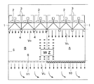
図1に示されるようにクリーンルームCRは、仕切り壁5によりワーキングゾーンWZと、ユーティリティゾーンUZとに区画されている。前記ワーキングゾーンWZは、実際の製造作業が行われるスペースであり、前記ユーティリティゾーンUZはクリーンルームCRの内、ワーキングゾーンWZを取り巻く準清浄域のことであり、サービス領域とも呼ばれ、製造装置の後部とそれに連絡される諸ユーティリティ配管、ダクト類が接続されるスペースである。また、ワーキングゾーンWZを外部の汚染から守るバッファゾーンとしての役割も果たしている。
【0018】
前記ワーキングゾーンWZにおいては、室内の上方位置に、格子状に組まれた天井フレーム4、4…の各枠部に対して、ケーシング3内に小型の送風機2を内蔵するとともに、HEPAフィルター、VEPAフィルター、ULPAフィルター等の高性能フィルターまたは超高性能フィルター1、1…(以下、高性能フィルターという。)と一体化を図ったファンフィルターユニットが取り付けられている。この天井フレーム4、4…と接触する高性能フィルター1、1…の周囲には、シール等により完全な気密性が確保されている。
【0019】
また、床面はグレーチング床6となっており、前記高性能フィルター1、1…を通過してワーキングゾーンWZ内に流入した清浄空気は、このグレーチング床6を通り抜けて床下のリタンプレナムエリア(以下、リタンチャンバともいう。)7に流れ込んだ後、隣接するリタンダクト8を通り、再びワーキングゾーンWZに供給されるようになっている。一方、ユーティリティゾーンUZでは、簡易的に引抜きファン9により室内空気を取り込み、再び天井裏チャンバに供給することで空気を循環させるようになっている。
【0020】
前記ワーキングゾーンWZは、作業台や製造装置などが設置され実際に製品が製造される図面右側の生産ゾーンAと、作業用通路等となる図面左側の非生産ゾーンBとに区画され、生産ゾーンA側ではクラス100の清浄度を確保するために前記送風機2の電動機回転をインバータ制御することにより、生産ゾーンA側の吹出し速度VA が0.25〜0.5m/sec 程度に設定され、一方非生産ゾーンB側ではクラス1000でよいため吹出し速度VB が0.1〜0.2m/sec 程度に設定される。
【0021】
また、ワーキングゾーンWZの床側においては、グレーチング床6の下面側に対して、生産ゾーンA側に対しては相対的に空気抵抗の大きい空気抵抗体10が設置されるとともに、非生産ゾーンB側に対しては相対的に空気抵抗の小さい空気抵抗体11が設置される。この空気抵抗体10、11としては、紙、不織布、織布、金網や有孔板(単板またはスライド式複板)等が好適に用いられるが、空気抵抗を示すものであれば何でもよい。前記生産ゾーンAおよび非生産ゾーンBに配設される空気抵抗体10、11の空気抵抗値は気流速度Vの一次関数となるが、高性能フィルター1から吹き出された清浄空気の気流速度に対応して、生産ゾーンAには空気抵抗の大きいものが、また非生産ゾーンBには空気抵抗の小さいものが用いられ、これら空気抵抗体10、11の空気抵抗差によって床面の吸込み速度VC(図2参照)がほぼ均一になるように調整される。本例では、生産ゾーンAと非生産ゾーンBの両者に空気抵抗体10、11を設けたが、もちろん、非生産ゾーンB側はグレーチング床6のままとし、前記生産ゾーンA側にのみ空気抵抗体10を設けることにより床面の吸込み速度VC がほぼ均一になるように調整することでもよい。
【0022】
このように気流の吹出し速度と吸込み速度とを調整することにより、高い吹出し速度に設定された側の生産ゾーンAがたとえばクラス100の高清浄度領域に維持されるとともに、図2に示されるように、生産ゾーンA側から非生産ゾーンB側に向けた水平気流(正確には、気流の水平方向成分)が生起され、仮に作業通路を人が歩いて塵埃が巻き上げられた場合でも、塵埃が生産ゾーンA側に侵入することなく、非生産ゾーンB側に拡散する挙動を示すため、生産ゾーンA側においてより確実に高い清浄度が確保されるようになっている。
【0023】
次いで、図3は本発明に係る第2実施例を示したもので、一つの天井裏給気チャンバ12に対して給気ダクト13を通じて空気が供給され、床下のリタンチャンバ15の一方側端部に形成したダクト吸込口14から空気を吸込み、空気を循環させるようにした空気循環システムである。
【0024】
上記第2実施例においては、高性能フィルター1からの吹出し速度調整は、高性能フィルター1に貼設した空気抵抗体16、17により行っている。
【0025】
一方で、本空気循環システム例では、リタンチャンバ15の一方側端部のみからダクト吸込みを行っているため、吸込口近傍位置と遠方位置とでは負圧程度が異なり、吸込アンバランスが生じる場合があるが、この吸込アンバランスをも考慮して床側の空気抵抗体10、11を設置することもできる。この場合の設計手順は、同図に示すように、リタンチャンバ15の負圧アンバランスを均一とするための空気抵抗勾配線(I)と、クリーンルーム内における生産ゾーンAおよび非生産ゾーンBの気流速度を均一とするための空気抵抗線(II)とを重ね合わせた空気抵抗線(III) を描き、次いで、一定傾斜勾配の空気抵抗値を持つ空気抵抗体を得ることは通常困難であるため、この重ね合わせ空気抵抗線に沿う階段状の設計空気抵抗線を決定し、段階的に空気抵抗値を変化させ得るような各空気抵抗体の素材を選択して配置する。図示の例では、生産ゾーンAおよび非生産ゾーンB共に2ブロックに分割し、ダクト吸込口14側から空気抵抗の大きい順に空気抵抗体10A、10B、11A、11Bを配置している。
【0026】
前記グレーチング床6側における吸込み速度調整手段としては、他に図4に示されるボリュームダンパ機構とすることもできる。グレーチング床6下のリタンチャンバを複数の小室20、20…に区分し、これらの小室20、20…とリタンダクト22とを連通させ、各小室20からリタンダクト22への入部に対してボリュームダンパ21、21…を設け、これら各ボリュームダンパ21、21…の開度調整により生産ゾーンAと非生産ゾーンBとの吸込み速度を均一化することもできる。この場合、各小室20、20…に風量センサ等を設け、これら風量センサからの情報を基に各前記ボリュームダンパ21、21…の開度を自動制御するようにしてもよい。
【0027】
ところで、床面における吸込み速度は、吹出し風量と吸込み風量とがバランスするように、下式(1)に示される計算式により、生産ゾーンA側における吹出し速度VA と非生産ゾーンB側における吹出し速度VB と、これら各領域の面積(AA 、AB )の割合を考慮した加重平均値とするのがよい。
【0028】
【数1】

【実施例】
以下、本発明の効果を実験によって明らかにする。
1.実験方法
本発明に係るトンネル方式と従来のトンネル方式とで水平方向の気流性状を観察した。具体的には、図5に示されるように、生産ゾーンA側では吹出し速度0.3m/sec で清浄空気の吹出しを行い、非生産ゾーンBではこれより吹出し速度を緩和させて(0.1m/sec 、0.15m/sec 0.2m/sec の3ケース)吹出しを行い、床面側では吸込み速度を均一として空気を流した場合(本発明方式)と、図6に示されるように、生産ゾーンA側では吹出し速度0.3m/sec で清浄空気の吹出しを行い、非生産ゾーンBではこれより吹出し速度を緩和させて(0.1m/sec 、0.15m/sec 0.2m/sec の3ケース)吹出しを行い、床面側では生産ゾーンAの気流速度、非生産ゾーンBの気流速度に対応した吸込み速度として空気を流した場合(従来方式)とについて、領域境界部を中心としてその近傍位置の水平気流性状を超音波3次元風速計により観察するとともに、発塵源位置の高さを変えて塵埃を発生させてその拡散挙動を観察した。
【0030】
2.実験結果
A.水平方向の気流性状
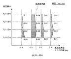
天井面での吹出し速度を生産ゾーンA側(高風速領域)で0.3m/sec 、非生産ゾーンB側(低風速領域)で0.15m/sec としたケースについて、中央の風速境界線からそれぞれの側に0.3m離れた位置と0.9m離れた位置とで水平方向気流の状態について測定を行い、本発明方式の結果を図7に、従来方式の結果を図8に示した。なお、図中、符号は高風速側から低風速側への流れを正としている。
【0031】
実験結果から明らかなように、本発明方式の結果を示した図7においては、±0.3m位置、±0.9m位置のいずれの位置においても、天井面近傍(FL+2.5m)から床面直上(FL+0.7m)までのどの高さ位置であっても、生産ゾーンA(高風速領域)から非生産ゾーンB(低風速領域)に向かって気流の流れ出しが起きているのに対して、従来方式の結果を示した図8においては、FL+1.3m以上の高さでは生産ゾーンAから非生産ゾーンBに向かって気流の流れ出しが起きているのであるが、FL+1.3m以下になると、気流の方向が逆になり非生産ゾーンBから生産ゾーンAに向かって流れ込みが生じていることが判る。
【0032】
B.塵埃拡散実験
天井面での吹出し速度を生産ゾーンA側(高風速領域)で0.3m/sec 、非生産ゾーンB側(低風速領域)で0.15m/sec としたケースについて、塵埃発生器を風速境界線のFL+1.5m、FL+1.9m、FL+2.7mの各位置に設置して、塵埃の拡散程度を観察した。本発明方式の結果を図9に、従来方式の結果を図10に示した。
【0033】
実験結果から明らかなように、本発明方式の場合には、図9に示されるようにFL+1.5mより低いところでは塵埃が生産ゾーンAから非生産ゾーンB側に流出するように拡散していることが確認されたのに対して、従来方式の場合には、図10に示されるように生産ゾーンA側に流入するように塵埃が拡散していることが確認された。この結果は、上記水平方向の気流性状の結果を反映する結果となっている。
【0034】
また、本発明方式の場合において、FL+0.9m位置での風速境界線から生産ゾーンA側への拡散距離Lを、非生産ゾーンB側領域の吹出し速度を0.2m/sec 、0.15m/sec 0.1m/sec に変えた場合の各ケースについて測定し、その結果を表1に示す。
【0035】
【表1】
表1より、発塵源高さFL+1.5mのケースにおいて、BパタンとCパタンとで数値の逆転が見られるものの、全体的傾向として非生産ゾーンBの吹出し速度が高い程、拡散距離Lが小さくなることが確認された。また、拡散距離Lはオーダー的に概ね40cm以下とし得ることも同時に確認された。
【0037】
【発明の効果】
以上詳説のとおり本発明によれば、トンネル方式のクリーンルーム構造において、風速境界近傍のどの高さ位置であっても高風速側領域から低風速側領域への流れ出しが生じるようになる。したがって、作業通路を人が歩いて塵埃が巻き上げられた場合でも、低風速側領域に塵埃が拡散するようになり、常に高風速側領域をより確実に高清浄度状態に維持し得る。
【図面の簡単な説明】
【図1】 第1実施例に係るクリーンルームの概略構造図である。
【図2】 その要部拡大図である。
【図3】 第2実施例に係るクリーンルームの概略構造図である。
【図4】 第3実施例に係るクリーンルームの概略構造図である。
【図5】 実施例における本発明方式の気流状態図である。
【図6】 実施例における従来方式の気流状態図である。
【図7】 本発明方式の水平方向気流性状図である。
【図8】 従来方式の水平方向気流性状図である。
【図9】 本発明方式の塵埃拡散状況の実験結果図である。
【図10】 従来方式の塵埃拡散状況の実験結果図である。
【図11】 従来のベイ方式によるクリーンルーム概略構造図である。
【図12】 従来のトンネル方式によるクリーンルーム概略構造図である。
【符号の説明】
1…高性能フィルター、2…送風機、3…ケーシング、5…仕切り壁、6…グレーチング床、7…リタンプレナムエリア、10・11・16・17…空気抵抗体、WZ…ワーキングゾーン、UZ…ユーティリティゾーン、A…生産ゾーン、B…非生産ゾーン。[0001]
BACKGROUND OF THE INVENTION
In the tunnel type clean room in which the clean room is partitioned into a high cleanliness region and a low cleanliness region, and the cleanliness is different in each region, the low cleanliness region generated at the boundary of the region is increased. The present invention relates to a clean room structure that prevents dust from flowing out to the cleanliness area side.
[0002]
[Prior art]
In semiconductor and film manufacturing factories and precision machinery factories, even a small amount of airborne particles can adhere to the product being manufactured and cause product defects. Maintain, work on product quality and reliability, and improve yield. A room cleaned for such a purpose is called a clean room, and a very high clean environment is secured.
[0003]
In the clean room, in order to keep the air clean, for example, a high performance filter is disposed on the ceiling or wall part, and a number of air discharge holes are formed on the floor or wall part, and circulated in the middle of the circulation path. A fan is provided to circulate air so as to go around the high performance filter.
[0004]
Conventionally, there are various types of air purification methods in a clean room, such as a down flow method and a bay method. The downflow type is also called the entire surface vertical laminar flow method, and a high-performance filter is arranged on almost one surface of the ceiling, while a floor is used as a grating to form a suction port so that the air fed from the back of the ceiling This is a system in which after passing through the performance filter and sent to the room, it is sucked from the suction port and circulated. In this case, the vertical air velocity is set to about 0.25 to 0.5 m / sec. If the blowing speed on the ceiling surface is 0.5 m / sec, the ventilation frequency is 400 to 600 times / h or more. . Although this method can maintain the cleanliness class 100 to 1 by a very effective means for removing fine particles, a huge amount of air must be circulated, and naturally the capacity of the air conditioning equipment does not increase. There is a problem that initial cost and running cost increase.
[0005]
On the other hand, as shown in FIG. 11, the bay method has a relatively low cleanliness by installing a working zone WZ in which production activities are actually performed in a clean room and a high cleanliness class is required, and facilities. The initial cost and running cost are reduced by partitioning it into a utility zone UZ, which is sufficient in the class.
[0006]
In recent years, this bay-type working zone can be used in the upper part of the production line that requires a strict cleanliness class (for example, class 100) or in the vicinity thereof, and a relaxed cleanliness class (for example, class 1000 or 10,000). A so-called tunnel method is adopted in which air conditioning facilities are planned separately for the passages. In this tunnel system, as shown in FIG. 12, a so-called tunnel unit is continuously suspended on the production line and divided into cleanliness classes such as A part and B part. Therefore, the vertical air velocity is set to about 0.1 to 0.2 m / sec. The surrounding A part is made into a high cleanliness class tunnel-like space, and the air supply in the work passage B part is reduced from the A part to relax the cleanliness class. In this case, the suction speed to the floor surface is the suction speed corresponding to the air flow speed, that is, suction is performed at a relatively fast speed in the A part, and suction is performed at a slow speed in the B part. As prior arts related to this method, there can be mentioned JP-A-56-162335, JP-A-59-185923, and Japanese Patent Application No. 1-245074.
[0007]
The JP 56-162335 and No. JP 59-185923 divides the clean room and the production line and the non-production line, in addition to operating the air supply ceiling Chang bar or al, relatively production The present invention relates to an invention in which the vertical airflow velocity on the line side is made larger than the vertical airflow velocity on the non-production line side, and the latter Japanese Patent Application No. 1-245074 is woven, non-woven fabric, wire mesh, perforated for high performance filters. The present invention relates to an invention in which air flow speeds on a production line side and a non-production line side can be arbitrarily adjusted by attaching air resistors such as plates in an overlapping manner.
[0008]
[Problems to be solved by the invention]
In the tunnel method, it is true that the production line area where the air velocity is increased is much more clean and the cost is reduced. It is the clean method most used in factories.
[0009]
However, the details will be clarified by the experiment described later. According to the experiments by the present inventors, particularly in the vicinity of the boundary between the production line area (high wind speed side area) and the non-production area (low wind speed side area). When the airflow condition was observed, the airflow was flowing from the high wind speed side area toward the low wind speed side area in the ceiling side area (approximately FL + 1.m or more), but on the floor side (approximately FL + 1.m or less). On the contrary, the new fact that the airflow flows from the low wind speed area toward the high wind speed area is found. Even if it is only in the vicinity of the floor side, the intrusion of dust toward the high wind speed side area means that, for example, when dust is rolled up at the intrusion position, the dust is in a wider range of the high wind speed side area. It means that dust can diffuse.
[0010]
Accordingly, an object of the present invention is to allow a flow from the high wind speed side region to the low wind speed side region at any height position in the vicinity of the wind speed boundary in the tunnel type clean room structure, and a person walks along the work passage. An object of the present invention is to provide a clean room structure in which even when dust is rolled up, the dust is diffused into the low wind speed side region so that the high wind speed side region can be more reliably maintained in a high cleanliness state.
[0011]
[Means for Solving the Problems]
In order to solve the above problems, the present invention provides an air filter on the ceiling side, an air suction hole is formed on the floor surface, and clean air is rectified from the ceiling side to the floor side, and the entire vertical laminar flow is In a clean room that uses a flow method
The same space of this clean room is divided into a high cleanliness area and a low cleanliness area, on the ceiling blowout side; the blowout speed on the high cleanliness area side is 0.25 to 0.5 m / sec , and the low cleanliness while adjusting the blowing rate adjusting means so that 0.1 to 0.2 m / sec velocity blowing in degrees region side,
On the floor surface suction side; the suction speed adjusting means can be adjusted so that the suction speed to the floor surface on the high cleanliness region side and the suction speed to the floor surface on the low cleanness region side are substantially uniform ,
The blowing speed adjusting means is an air resistor attached to the air speed control of the blower disposed on the ceiling side of the air filter or the air filter, and the suction speed adjusting means is an air volume adjusting damper or floor provided on the floor lower side. It is the air resistor attached to .
[0012]
In this case , the suction speed to the floor surface from the supply / exhaust balance is a weighted average value considering the blowing speed on the high cleanliness area side, the blowing speed on the low cleanliness side, and the area ratio of each of these areas. Is good.
[0013]
In the case of the tunnel method that has been proposed in the past, even if the blowing speed from the ceiling surface is adjusted, the suction speed is adjusted on the floor surface side, and further on each side of the ceiling and floor surface. Even if the air velocity is adjusted, all the proposals to achieve a uniform laminar flow state with different wind speeds in the production zone (high wind speed region) and non-production zone (low wind speed region) are all. . Therefore, when both suction speeds are compared, it is necessary to set the suction speed corresponding to the airflow speed. Naturally, the suction speed is high on the production zone side and the suction speed is low on the non-production zone side.
[0014]
On the other hand, in the case of the invention of the present application, the production zone side is blown from the ceiling air filter surface as usual at a relatively high blowing speed, while the floor side is discharged at a uniform suction speed. To be adjusted. That is, the conventional method is “different wind speed blowing-different wind speed suction”, whereas the present invention is “different wind speed blowing-same wind speed suction”.
[0015]
From a macro perspective, the conventional method maintains a relatively high cleanness in the high wind speed region and a low cleanness in the low wind speed region. There have been no reports observed in the past, and it was generally considered that the initial objectives were sufficiently achieved. However, as will be apparent from the experiments described later, the experiments by the present inventors have shown that, in the floor side area (approximately FL + 1.m or less) of the boundary portion of each area, the low wind speed area moves from the high wind speed area. A new fact that the air current is flowing in was discovered. The present invention prevents this flow out to the high wind speed side region.
[0016]
In this specification, in the comparison between the production zone and the non-production zone, the production zone side is expressed as a high wind speed area or a high cleanliness area, and the non-production zone is expressed as a low wind speed area or a low cleanliness area. However, in the actual wind speed adjustment in each region, the air flow velocity in the production zone is set to a normal level (as it is), and the air flow velocity in the non-production zone is decreased to give a relative difference.
[0017]
DETAILED DESCRIPTION OF THE INVENTION
Hereinafter, embodiments of the present invention will be described in detail with reference to the drawings.
As shown in FIG. 1, the clean room CR is partitioned into a working zone WZ and a utility zone UZ by a
[0018]
In the working zone WZ, a
[0019]
Further, the floor is a
[0020]
The working zone WZ is divided into a production zone A on the right side of the drawing where a work table, a manufacturing apparatus, etc. are installed and actually manufactured, and a non-production zone B on the left side of the drawing, which serves as a working passage, etc. On the A side, the blower speed V A on the production zone A side is set to about 0.25 to 0.5 m / sec by inverter-controlling the motor rotation of the
[0021]
On the floor side of the working zone WZ, an
[0022]
Thus, by adjusting the blowing speed and the suction speed of the airflow, the production zone A on the side set to a high blowing speed is maintained in the high cleanliness region of class 100, for example, and as shown in FIG. In addition, a horizontal airflow (more precisely, the horizontal component of the airflow) from the production zone A side to the non-production zone B side is generated, and even if a person walks up the work path and dust is rolled up, In order to show the behavior of diffusing to the non-production zone B side without entering the production zone A side, a higher cleanliness is ensured more reliably on the production zone A side.
[0023]
Next, FIG. 3 shows a second embodiment according to the present invention, in which air is supplied to one ceiling backside
[0024]
In the second embodiment, the blowout speed adjustment from the
[0025]
On the other hand, in this air circulation system example, duct suction is performed only from one end portion of the
[0026]
As the suction speed adjusting means on the
[0027]
By the way, the suction speed on the floor surface is calculated by the following formula (1) so that the blown air volume and the sucked air volume are balanced, and the blow speed V A on the production zone A side and the blown air on the non-production zone B side. The weighted average value considering the speed V B and the ratio of the area (A A , A B ) of each region is preferably used.
[0028]
[Expression 1]
【Example】
Hereinafter, the effects of the present invention will be clarified through experiments.
1. Experimental Method Horizontal airflow characteristics were observed in the tunnel method according to the present invention and the conventional tunnel method. Specifically, as shown in FIG. 5, clean air is blown at a blowing speed of 0.3 m / sec on the production zone A side, and the blowing speed is reduced (0.1 m) in the non-production zone B. / sec, 0.15 m / sec 0.2 m / sec)) When blowing out and flowing air with the suction speed uniform on the floor side (the present invention method), as shown in FIG. On the production zone A side, clean air is blown at a blowing speed of 0.3 m / sec. In the non-production zone B, the blowing speed is reduced (0.1 m / sec, 0.15 m / sec, 0.2 m / sec). 3 cases) When air is blown out and air is flown as the suction speed corresponding to the airflow speed of the production zone A and the airflow speed of the non-production zone B on the floor side (conventional method), the region boundary is the center. The horizontal airflow characteristics in the vicinity are measured by an ultrasonic three-dimensional anemometer. With observation to observe the diffusion behavior by changing the height of the dust source position to generate dust.
[0030]
2. Experimental results A. Horizontal airflow characteristics The case where the blowing speed on the ceiling surface is 0.3 m / sec on the production zone A side (high wind speed area) and 0.15 m / sec on the non-production zone B side (low wind speed area) The horizontal airflow state was measured at a position 0.3 m away and 0.9 m away on each side from the wind speed boundary line, and the results of the method of the present invention are shown in FIG. 7 and the results of the conventional method are shown. This is shown in FIG. In the figure, the sign is positive for the flow from the high wind speed side to the low wind speed side.
[0031]
As is apparent from the experimental results, in FIG. 7 showing the results of the method of the present invention, the floor surface from the vicinity of the ceiling surface (FL + 2.5 m) at both the ± 0.3 m position and the ± 0.9 m position. At any height position up to just above (FL + 0.7m), airflow is flowing from production zone A (high wind speed region) to non-production zone B (low wind speed region), In FIG. 8 showing the result of the conventional method, the flow of airflow from the production zone A toward the non-production zone B occurs at a height of FL + 1.3 m or more. It can be seen that the direction of is reversed and inflow occurs from the non-production zone B toward the production zone A.
[0032]
B. Dust diffusion experiment Dust generator for a case where the blowing speed on the ceiling surface is 0.3 m / sec on the production zone A side (high wind speed region) and 0.15 m / sec on the non-production zone B side (low wind speed region). Was installed at each position of FL + 1.5m, FL + 1.9m, FL + 2.7m on the wind speed boundary line, and the degree of dust diffusion was observed. The result of the method of the present invention is shown in FIG. 9, and the result of the conventional method is shown in FIG.
[0033]
As is clear from the experimental results, in the case of the method of the present invention, as shown in FIG. 9, dust is diffused so as to flow out from the production zone A to the non-production zone B side at a position lower than FL + 1.5 m. On the other hand, in the case of the conventional method, it was confirmed that dust was diffused so as to flow into the production zone A side as shown in FIG. This result reflects the result of the horizontal airflow property.
[0034]
In the case of the method of the present invention, the diffusion distance L from the wind speed boundary line at the FL + 0.9 m position to the production zone A side is set to be the blowing speed in the non-production zone B side region is 0.2 m / sec, 0.15 m / Measurement was made for each case when sec was changed to 0.1 m / sec, and the results are shown in Table 1.
[0035]
[Table 1]
From Table 1, in the case where the dust generation source height is FL + 1.5 m, the numerical value is reversed between the B pattern and the C pattern. However, as the overall tendency, the diffusion speed L increases as the blowing speed of the non-production zone B increases. It was confirmed to be smaller. It was also confirmed at the same time that the diffusion distance L could be about 40 cm or less in order.
[0037]
【The invention's effect】
As described above, according to the present invention, in the tunnel type clean room structure, the flow from the high wind speed side region to the low wind speed side region occurs at any height position near the wind speed boundary. Therefore, even when a person walks along the work path and the dust is wound up, the dust diffuses into the low wind speed side region, and the high wind speed side region can always be maintained in a highly clean state more reliably.
[Brief description of the drawings]
FIG. 1 is a schematic structural diagram of a clean room according to a first embodiment.
FIG. 2 is an enlarged view of a main part thereof.
FIG. 3 is a schematic structural diagram of a clean room according to a second embodiment.
FIG. 4 is a schematic structural diagram of a clean room according to a third embodiment.
FIG. 5 is an airflow state diagram of the method of the present invention in an example.
FIG. 6 is an airflow state diagram of a conventional system in an example.
FIG. 7 is a horizontal airflow property diagram of the method of the present invention.
FIG. 8 is a horizontal airflow property diagram of a conventional method.
FIG. 9 is an experimental result diagram of the dust diffusion state of the method of the present invention.
FIG. 10 is an experimental result diagram of a conventional dust diffusion state.
FIG. 11 is a schematic structural diagram of a clean room using a conventional bay method.
FIG. 12 is a schematic structural diagram of a clean room by a conventional tunnel method.
[Explanation of symbols]
DESCRIPTION OF
Claims (2)
このクリーンルームの同一空間内を高清浄度領域と低清浄度領域とに区画し、 天井吹出し側において;前記高清浄度領域側における吹出し速度を0.25〜0.5 m / sec 、前記低清浄度領域側における吹出し速度を0.1〜0.2 m / sec となるように吹出し速度調整手段により調整する一方、
床面吸込み側において;前記高清浄度領域側における床面への吸込み速度と前記低清浄度領域側における床面への吸込み速度とがほぼ均一となるように吸込み速度調整手段により調整可能とし、
前記吹出し速度調整手段は、エアフィルターの天井裏側に配された送風機の回転数制御またはエアフィルターに取り付けた空気抵抗体であり、前記吸込み速度調整手段は床下側に設けた風量調整ダンパまたは床面に取り付けた空気抵抗体であることを特徴とするクリーンルーム構造。In a clean room where an air filter is installed on the ceiling side, an air suction hole is formed on the floor surface, and clean air flows in a rectified state from the ceiling side to the floor side in an entirely vertical laminar flow system ,
The same space of this clean room is divided into a high cleanliness area and a low cleanliness area, on the ceiling blowout side; the blowout speed on the high cleanliness area side is 0.25 to 0.5 m / sec , and the low cleanliness while adjusting the blowing rate adjusting means so that 0.1 to 0.2 m / sec velocity blowing in degrees region side,
On the floor surface suction side; the suction speed adjusting means can be adjusted so that the suction speed to the floor surface on the high cleanliness region side and the suction speed to the floor surface on the low cleanness region side are substantially uniform ,
The blowing speed adjusting means is an air resistor attached to the air speed control of the blower disposed on the ceiling side of the air filter or the air filter, and the suction speed adjusting means is an air volume adjusting damper or floor provided on the floor lower side. A clean room structure characterized by being an air resistor attached to .
Priority Applications (1)
| Application Number | Priority Date | Filing Date | Title |
|---|---|---|---|
| JP29679996A JP3808567B2 (en) | 1996-11-08 | 1996-11-08 | Clean room structure |
Applications Claiming Priority (1)
| Application Number | Priority Date | Filing Date | Title |
|---|---|---|---|
| JP29679996A JP3808567B2 (en) | 1996-11-08 | 1996-11-08 | Clean room structure |
Publications (2)
| Publication Number | Publication Date |
|---|---|
| JPH10141723A JPH10141723A (en) | 1998-05-29 |
| JP3808567B2 true JP3808567B2 (en) | 2006-08-16 |
Family
ID=17838298
Family Applications (1)
| Application Number | Title | Priority Date | Filing Date |
|---|---|---|---|
| JP29679996A Expired - Lifetime JP3808567B2 (en) | 1996-11-08 | 1996-11-08 | Clean room structure |
Country Status (1)
| Country | Link |
|---|---|
| JP (1) | JP3808567B2 (en) |
Cited By (1)
| Publication number | Priority date | Publication date | Assignee | Title |
|---|---|---|---|---|
| KR20180069249A (en) * | 2016-12-15 | 2018-06-25 | 주식회사 시스웍 | Method and apparatus for monitoring direction and intensity of airflow of clean room for improving yield |
Families Citing this family (4)
| Publication number | Priority date | Publication date | Assignee | Title |
|---|---|---|---|---|
| JP5195899B2 (en) * | 2010-12-28 | 2013-05-15 | ダイキン工業株式会社 | Clean room air conditioning system |
| JP5366030B2 (en) * | 2011-09-22 | 2013-12-11 | 村田機械株式会社 | Automated warehouse for clean rooms |
| JP6531810B2 (en) * | 2017-12-01 | 2019-06-19 | 澁谷工業株式会社 | Sterile working system |
| JP2019173267A (en) * | 2018-03-26 | 2019-10-10 | ダイキン工業株式会社 | Watermark stairway for clean room and indoor system provided therewith |
Family Cites Families (4)
| Publication number | Priority date | Publication date | Assignee | Title |
|---|---|---|---|---|
| JPS61165539A (en) * | 1985-01-16 | 1986-07-26 | Nec Corp | Air condition ing system |
| JPS62169949A (en) * | 1986-01-21 | 1987-07-27 | Nec Corp | Filter apparatus |
| JPS63176944A (en) * | 1987-01-19 | 1988-07-21 | Mitsubishi Electric Corp | Clean room |
| JPH0646240U (en) * | 1992-11-27 | 1994-06-24 | 株式会社大氣社 | Clean room |
-
1996
- 1996-11-08 JP JP29679996A patent/JP3808567B2/en not_active Expired - Lifetime
Cited By (2)
| Publication number | Priority date | Publication date | Assignee | Title |
|---|---|---|---|---|
| KR20180069249A (en) * | 2016-12-15 | 2018-06-25 | 주식회사 시스웍 | Method and apparatus for monitoring direction and intensity of airflow of clean room for improving yield |
| KR101880426B1 (en) | 2016-12-15 | 2018-07-27 | 주식회사 시스웍 | Method and apparatus for monitoring direction and intensity of airflow of clean room for improving yield |
Also Published As
| Publication number | Publication date |
|---|---|
| JPH10141723A (en) | 1998-05-29 |
Similar Documents
| Publication | Publication Date | Title |
|---|---|---|
| JPS625031A (en) | Clean room partially having different cleaning degrees | |
| JP3808567B2 (en) | Clean room structure | |
| KR20200086085A (en) | Air Conditioner with Function of Fine Dust Removal | |
| JP2551923Y2 (en) | Clean room | |
| JPS6127435A (en) | Preventing device for inducting and mixing contaminated air in air cleaning system | |
| JP2536188B2 (en) | Air purifier | |
| JP2004286436A (en) | Air flow rate control device and clean room air conditioning system using the same | |
| JPH10311556A (en) | Air-conditioning method and air conditioner | |
| JPS62299641A (en) | Air circulation method for clean room | |
| JP2003214668A (en) | Clean room | |
| JP3420722B2 (en) | Local air purifier | |
| JPS59185923A (en) | Location-changeable formation of tunnel type clean room in compartment | |
| JPH0544663Y2 (en) | ||
| JP3013098B2 (en) | Filter unit for ceiling system | |
| JPH10185260A (en) | Air distributor for blowing air | |
| JPH03113221A (en) | Local cleaning air flow control device | |
| JPH0325074Y2 (en) | ||
| JPS62182541A (en) | Clean room | |
| JP3639021B2 (en) | Filter unit for tunnel type clean room | |
| JP2001153415A (en) | Ventilation air-conditioning system and ventilation air- conditioning method | |
| JP4356860B2 (en) | Iron making equipment | |
| JP4256185B2 (en) | Airflow control structure in a clean room | |
| JPH06213503A (en) | Air conditioning apparatus for low temperature factory for food, meat and the like | |
| JP3894076B2 (en) | Clean room | |
| JPS629135A (en) | Air conditioner |
Legal Events
| Date | Code | Title | Description |
|---|---|---|---|
| A977 | Report on retrieval |
Free format text: JAPANESE INTERMEDIATE CODE: A971007 Effective date: 20060130 |
|
| A131 | Notification of reasons for refusal |
Free format text: JAPANESE INTERMEDIATE CODE: A131 Effective date: 20060203 |
|
| A521 | Written amendment |
Free format text: JAPANESE INTERMEDIATE CODE: A523 Effective date: 20060404 |
|
| TRDD | Decision of grant or rejection written | ||
| A01 | Written decision to grant a patent or to grant a registration (utility model) |
Free format text: JAPANESE INTERMEDIATE CODE: A01 Effective date: 20060512 |
|
| A61 | First payment of annual fees (during grant procedure) |
Free format text: JAPANESE INTERMEDIATE CODE: A61 Effective date: 20060518 |
|
| R150 | Certificate of patent or registration of utility model |
Free format text: JAPANESE INTERMEDIATE CODE: R150 |
|
| S531 | Written request for registration of change of domicile |
Free format text: JAPANESE INTERMEDIATE CODE: R313531 |
|
| FPAY | Renewal fee payment (event date is renewal date of database) |
Free format text: PAYMENT UNTIL: 20090526 Year of fee payment: 3 |
|
| R350 | Written notification of registration of transfer |
Free format text: JAPANESE INTERMEDIATE CODE: R350 |
|
| FPAY | Renewal fee payment (event date is renewal date of database) |
Free format text: PAYMENT UNTIL: 20100526 Year of fee payment: 4 |
|
| FPAY | Renewal fee payment (event date is renewal date of database) |
Free format text: PAYMENT UNTIL: 20100526 Year of fee payment: 4 |
|
| FPAY | Renewal fee payment (event date is renewal date of database) |
Free format text: PAYMENT UNTIL: 20110526 Year of fee payment: 5 |
|
| FPAY | Renewal fee payment (event date is renewal date of database) |
Free format text: PAYMENT UNTIL: 20110526 Year of fee payment: 5 |
|
| FPAY | Renewal fee payment (event date is renewal date of database) |
Free format text: PAYMENT UNTIL: 20120526 Year of fee payment: 6 |
|
| FPAY | Renewal fee payment (event date is renewal date of database) |
Free format text: PAYMENT UNTIL: 20130526 Year of fee payment: 7 |
|
| FPAY | Renewal fee payment (event date is renewal date of database) |
Free format text: PAYMENT UNTIL: 20130526 Year of fee payment: 7 |
|
| FPAY | Renewal fee payment (event date is renewal date of database) |
Free format text: PAYMENT UNTIL: 20140526 Year of fee payment: 8 |
|
| EXPY | Cancellation because of completion of term |