JP3771233B2 - Liquid cooling jacket - Google Patents
Liquid cooling jacket Download PDFInfo
- Publication number
- JP3771233B2 JP3771233B2 JP2003349701A JP2003349701A JP3771233B2 JP 3771233 B2 JP3771233 B2 JP 3771233B2 JP 2003349701 A JP2003349701 A JP 2003349701A JP 2003349701 A JP2003349701 A JP 2003349701A JP 3771233 B2 JP3771233 B2 JP 3771233B2
- Authority
- JP
- Japan
- Prior art keywords
- liquid
- heat
- cooling jacket
- liquid cooling
- fins
- Prior art date
- Legal status (The legal status is an assumption and is not a legal conclusion. Google has not performed a legal analysis and makes no representation as to the accuracy of the status listed.)
- Expired - Fee Related
Links
Images


Classifications
-
- H—ELECTRICITY
- H05—ELECTRIC TECHNIQUES NOT OTHERWISE PROVIDED FOR
- H05K—PRINTED CIRCUITS; CASINGS OR CONSTRUCTIONAL DETAILS OF ELECTRIC APPARATUS; MANUFACTURE OF ASSEMBLAGES OF ELECTRICAL COMPONENTS
- H05K7/00—Constructional details common to different types of electric apparatus
- H05K7/20—Modifications to facilitate cooling, ventilating, or heating
-
- F—MECHANICAL ENGINEERING; LIGHTING; HEATING; WEAPONS; BLASTING
- F28—HEAT EXCHANGE IN GENERAL
- F28F—DETAILS OF HEAT-EXCHANGE AND HEAT-TRANSFER APPARATUS, OF GENERAL APPLICATION
- F28F3/00—Plate-like or laminated elements; Assemblies of plate-like or laminated elements
- F28F3/12—Elements constructed in the shape of a hollow panel, e.g. with channels
-
- F—MECHANICAL ENGINEERING; LIGHTING; HEATING; WEAPONS; BLASTING
- F28—HEAT EXCHANGE IN GENERAL
- F28D—HEAT-EXCHANGE APPARATUS, NOT PROVIDED FOR IN ANOTHER SUBCLASS, IN WHICH THE HEAT-EXCHANGE MEDIA DO NOT COME INTO DIRECT CONTACT
- F28D15/00—Heat-exchange apparatus with the intermediate heat-transfer medium in closed tubes passing into or through the conduit walls ; Heat-exchange apparatus employing intermediate heat-transfer medium or bodies
- F28D15/02—Heat-exchange apparatus with the intermediate heat-transfer medium in closed tubes passing into or through the conduit walls ; Heat-exchange apparatus employing intermediate heat-transfer medium or bodies in which the medium condenses and evaporates, e.g. heat pipes
-
- F—MECHANICAL ENGINEERING; LIGHTING; HEATING; WEAPONS; BLASTING
- F28—HEAT EXCHANGE IN GENERAL
- F28F—DETAILS OF HEAT-EXCHANGE AND HEAT-TRANSFER APPARATUS, OF GENERAL APPLICATION
- F28F3/00—Plate-like or laminated elements; Assemblies of plate-like or laminated elements
- F28F3/02—Elements or assemblies thereof with means for increasing heat-transfer area, e.g. with fins, with recesses, with corrugations
-
- H—ELECTRICITY
- H01—ELECTRIC ELEMENTS
- H01L—SEMICONDUCTOR DEVICES NOT COVERED BY CLASS H10
- H01L23/00—Details of semiconductor or other solid state devices
- H01L23/34—Arrangements for cooling, heating, ventilating or temperature compensation ; Temperature sensing arrangements
- H01L23/36—Selection of materials, or shaping, to facilitate cooling or heating, e.g. heatsinks
- H01L23/367—Cooling facilitated by shape of device
- H01L23/3672—Foil-like cooling fins or heat sinks
-
- H—ELECTRICITY
- H01—ELECTRIC ELEMENTS
- H01L—SEMICONDUCTOR DEVICES NOT COVERED BY CLASS H10
- H01L23/00—Details of semiconductor or other solid state devices
- H01L23/34—Arrangements for cooling, heating, ventilating or temperature compensation ; Temperature sensing arrangements
- H01L23/42—Fillings or auxiliary members in containers or encapsulations selected or arranged to facilitate heating or cooling
- H01L23/427—Cooling by change of state, e.g. use of heat pipes
-
- H—ELECTRICITY
- H01—ELECTRIC ELEMENTS
- H01L—SEMICONDUCTOR DEVICES NOT COVERED BY CLASS H10
- H01L23/00—Details of semiconductor or other solid state devices
- H01L23/34—Arrangements for cooling, heating, ventilating or temperature compensation ; Temperature sensing arrangements
- H01L23/46—Arrangements for cooling, heating, ventilating or temperature compensation ; Temperature sensing arrangements involving the transfer of heat by flowing fluids
- H01L23/473—Arrangements for cooling, heating, ventilating or temperature compensation ; Temperature sensing arrangements involving the transfer of heat by flowing fluids by flowing liquids
-
- H—ELECTRICITY
- H01—ELECTRIC ELEMENTS
- H01L—SEMICONDUCTOR DEVICES NOT COVERED BY CLASS H10
- H01L2924/00—Indexing scheme for arrangements or methods for connecting or disconnecting semiconductor or solid-state bodies as covered by H01L24/00
- H01L2924/0001—Technical content checked by a classifier
- H01L2924/0002—Not covered by any one of groups H01L24/00, H01L24/00 and H01L2224/00
Description
本発明は、電子機器の冷却に用いられる液冷システムにおいて、発熱体に取り付ける液冷ジャケットに関するものである。 The present invention relates to a liquid cooling jacket attached to a heating element in a liquid cooling system used for cooling an electronic device.
従来、電子機器の冷却に用いられる液冷ジャケットは発熱体の熱を冷却液に効率良く伝える必要がある。 Conventionally, a liquid cooling jacket used for cooling an electronic device needs to efficiently transfer heat of a heating element to a cooling liquid.
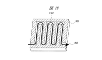
そこで、従来の液冷ジャケット内部の流路は、一例として、図18に示すように、蛇行状になっているものがあった。これはジャケット1301内部の流路1302を蛇行させ、冷却液の流れ1303がジャケット1301に極力接触するようにしたものである。これはジャケット1301内部の流路長を極力長くすることで、冷却液とジャケット内部壁面の接触面積を増やし、発熱体からの熱を効率良く冷却液に伝えようとする方法である。
Therefore, as an example, the flow path inside the conventional liquid cooling jacket has a meandering shape as shown in FIG. In this configuration, the
また、別の例として、図19に示すように、冷却液の流れ1401を複数の流れ1403a〜1403fに分配するものがあった。これは流路パスを複数もつことで、流路抵抗を低下させ、尚且つ冷却液と放熱フィン1402の接触面積を増やして効率良く熱を伝えようとする方法である(例えば、特許文献1参照)。
As another example, as shown in FIG. 19, there is one that distributes a
また、冷却液出入口が並んで配置されている方が配管上利便性に優れているため、冷却液出入口を並んで配置したものがあった。これは、図20に示すように、並んだ放熱フィン1501の中央に仕切り1502を設け、冷却液の流れ1401をUターンさせることで出入口を並んで配置する方法である(例えば、特許文献2参照)。
しかしながら、図18に示す様な蛇行状の流路では、流路長が長くなるほど流路抵抗が増大し、圧損が大きくなってしまうという問題があった。 However, the meandering flow path as shown in FIG. 18 has a problem that the flow path resistance increases and the pressure loss increases as the flow path length increases.
また、図19に示す様な、冷却液の流れを複数の流れに分配する流路では、冷却液を放熱フィン間に均一に流すことは困難という問題があった。詳しくは、液流には直進性があるため、入口近くにある放熱フィンには冷却液が流れにくくなるという問題があり、図19に示すように流速1403aから1403fにばらつきが生じることになる。これによって熱伝達率の低下が起こり、発熱体の熱を効率良く冷却液に伝えることができなくなる。 Further, in the flow path for distributing the coolant flow to a plurality of flows as shown in FIG. 19, there is a problem that it is difficult to uniformly flow the coolant between the heat radiation fins. Specifically, since the liquid flow is straight, there is a problem that it is difficult for the cooling liquid to flow through the heat dissipating fins near the inlet, and the flow rates 1403a to 1403f vary as shown in FIG. As a result, the heat transfer rate decreases, and the heat of the heating element cannot be efficiently transferred to the coolant.
また、図20に示す様な構造においても、放熱フィン間の液流1503aから1503cにばらつきが生じるという問題がある。詳しくは、出入口に近い流速1503bが一番速く他の1503aや1503cは流速が低下する。これによって熱伝達率の低下が起こり、発熱体の熱を効率良く冷却液に伝えることができなくなる。 Also in the structure as shown in FIG. 20, there is a problem that the liquid flows 1503a to 1503c between the radiation fins vary. Specifically, the flow velocity 1503b near the entrance / exit is the fastest, and the flow velocity of the other 1503a and 1503c decreases. As a result, the heat transfer rate decreases, and the heat of the heating element cannot be efficiently transferred to the coolant.
また、前記説明した何れの従来技術においても、より多くの接触面積を確保しようとしてジャケットサイズを大きくしても、中心の発熱体からの距離が遠くなるため、熱伝導効率向上が困難であるという問題がある。詳しくは、従来は、図21に示すようにベース301により水平方向に熱を広げて、各放熱フィン302に熱を伝えている。ところが重量や高さの関係からベース厚t1には制限があり、実際は厚くても7mm程度となるため、熱の広がり303は発熱体103周囲にとどまってしまい、端の放熱フィン302aまで熱を伝えることができない。即ちジャケットサイズが大きくなるほど、端の放熱フィンの冷却効果は低下する。
Also, in any of the above-described conventional techniques, even if the jacket size is increased in order to secure a larger contact area, the distance from the central heating element becomes longer, so that it is difficult to improve the heat conduction efficiency. There's a problem. In detail, conventionally, as shown in FIG. 21, heat is spread in the horizontal direction by the
本発明の目的は、熱伝達効率が良く、更に拡張性や組立性に優れた液冷ジャケットを提供することにある。 An object of the present invention is to provide a liquid cooling jacket having good heat transfer efficiency and excellent extensibility and assemblability.
本発明による液冷ジャケットは、発熱体に接合するベースと、ベースに対して垂直に立っている柱と、柱に取り付けられ、ベースと平行に配置された複数の放熱フィンと、複数の放熱フィンの間を所定の幅で埋める仕切りと、柱および放熱フィンを囲みベースと接合し、仕切りにより冷却液の流れが分けられる位置に冷却液の入口および出口が取り付けられたケースとを備え、複数の放熱フィンは、その厚みに比べて狭い間隔で配置されるものである。 The liquid cooling jacket according to the present invention includes a base joined to the heating element, a column standing perpendicular to the base, a plurality of radiation fins attached to the column and arranged in parallel with the base, and a plurality of radiation fins A partition that fills the space with a predetermined width, and a case in which pillars and radiating fins are enclosed and joined to the base, and a coolant inlet and outlet are attached at positions where the coolant flow is divided by the partition, The radiating fins are arranged at a narrow interval compared to the thickness.
(1)本発明によれば、液冷ジャケット内部の冷却液流は、複数流路を確保しているため、流路抵抗が低く、かつ冷却液の出入口の大きさは、並んだ放熱フィンの高さとほぼ同じにすることにより、各放熱フィン間の流速を均一にすることができる。 (1) According to the present invention, since the cooling liquid flow inside the liquid cooling jacket secures a plurality of flow paths, the flow resistance is low, and the size of the inlet / outlet of the cooling liquid is that of the radiating fins arranged side by side. By making it substantially the same as the height, the flow velocity between the radiation fins can be made uniform.
(2)本発明によれば、各放熱フィンに熱を伝える柱は太く、その高さは発熱体と接触しているベースから近距離にすることができるため、熱伝導効率が高い。 (2) According to the present invention, the pillars that transmit heat to the heat radiating fins are thick, and the height thereof can be a short distance from the base that is in contact with the heating element, so that the heat conduction efficiency is high.
(3)本発明によれば、放熱フィン間に設けられた仕切りにより冷却液の順路はUターンするので冷却液出入口を並んで配置でき、配管上利便性に優れている。 (3) According to the present invention, the coolant path is U-turned by the partition provided between the heat dissipating fins, so that the coolant inlet / outlet can be arranged side by side, and the convenience on the piping is excellent.
以下、本発明の実施の形態を図面に基づいて詳細に説明する。なお、実施の形態を説明するための全図において、同一の部材には原則として同一の符号を付し、その繰り返しの説明は省略する。 Hereinafter, embodiments of the present invention will be described in detail with reference to the drawings. Note that components having the same function are denoted by the same reference symbols throughout the drawings for describing the embodiment, and the repetitive description thereof will be omitted.
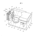
図1により、本発明の液冷ジャケットが適用される電子機器の構成を説明する。図1は、本発明の液冷ジャケットが適用される電子機器の斜視図であり、電子機器の例としてデスクトップ型パーソナルコンピュータの例を示している。 The configuration of an electronic apparatus to which the liquid cooling jacket of the present invention is applied will be described with reference to FIG. FIG. 1 is a perspective view of an electronic device to which the liquid cooling jacket of the present invention is applied, and shows an example of a desktop personal computer as an example of the electronic device.
図1において、筐体101の内部の底面付近にはマザーボード102があり、その上には発熱体であるCPU103、チップセット104、メモリ105が搭載されている。また、外部記憶装置として、HDD106、FDD107、CD−ROMドライブ108が搭載されている。CPU103には本発明による液冷ジャケット131が取り付けられている。
In FIG. 1, there is a
この液冷ジャケット131は銅あるいはアルミといった伝熱性に優れた金属からできている。
The
CPU103との接触面はサーマルコンパウンド、もしくは高熱伝導性シリコンゴムなどを挟んで圧着しており、CPU103で発生する熱が液冷ジャケット131に効率良く伝わる構造になっている。また、液冷ジャケット131の内部にはポンプ132により冷却液が流れており、熱が冷却液に伝わる構造になっている。
The contact surface with the
筐体101の背面外部には、放熱部であるヒートシンク135が配置されており、ヒートシンク135はベース135aおよびフィン135bから構成され、ベース135aの内部には冷却液が流れており、冷却液の熱がベース135a全体に伝わる構造になっている。なお、ベース135aには一定の液量を保持する機構も具備されている。即ち、ベース135aは冷却液のリザーブタンクとしても機能している。
A
フィン135bは筐体背面側を向くにように配置されている。つまり、フィン135bにファン113の風が当たるようになっている。
The
筐体101の背面に取り付けられたファン113は、ヒートシンク135と対面で配置されており、ファン113の風は直接フィン135bに当たるようになっている。より詳しくは、ファン113は、軸流ファンであり筐体101の内部側が吸気側、ヒートシンク135側が排気側となっている。ファン113の隣には電源109がある。
The
チューブ133および金属管134は、液冷ジャケット131とヒートシンク135を繋ぎ、内部に冷却液を流すことで液冷ジャケット131とヒートシンク135の熱輸送路となっている。
The
全体の配管は、金属管134を主体としており、部分的にゴム性のチューブ133を用いている。このチューブ133は曲げることができるため、CPU103の交換等のメンテナンスが容易になる。つまりファン113やヒートシンク135を外すこと無く、液冷ジャケット131をCPU103から外すことが可能である。また、チューブ133以外の配管を金属管134とすることで水分透過を抑制している。
The entire piping is mainly composed of a
冷却液の流れる順路は、ポンプ132−液冷ジャケット131−ヒートシンク135−再びポンプ132という順路である。このようにポンプ132により冷却液を流す方向はヒートシンク135通過後の冷却液を吸い込み、液冷ジャケット131に排出するようにしている。これによりポンプ132には冷却後の冷却液が流れ、ポンプ132の加熱を防いでいる。
The route through which the coolant flows is the route of pump 132 -liquid cooling jacket 131 -heat sink 135 -
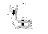
次に、図2〜図7により、本発明の液冷ジャケットの構造について説明する。図2は本発明の液冷ジャケットの分解図、図3は本発明の放熱フィンへの熱伝導を説明するための説明図、図4は本発明の柱にヒートパイプを用いた例を説明するための説明図、図5は本発明の冷却液の流れを説明するための説明図、図6は本発明の入口および出口の口径を小さくしたいときの形状を説明するための説明図、図7は本発明の入口および出口の口径を小さくしたいときの別の形状を説明するための説明図である。 Next, the structure of the liquid cooling jacket of the present invention will be described with reference to FIGS. FIG. 2 is an exploded view of the liquid cooling jacket of the present invention, FIG. 3 is an explanatory diagram for explaining heat conduction to the radiating fin of the present invention, and FIG. 4 illustrates an example in which a heat pipe is used for the pillar of the present invention. FIG. 5 is an explanatory diagram for explaining the flow of the coolant of the present invention, FIG. 6 is an explanatory diagram for explaining the shape of the present invention when the inlet and outlet diameters are to be reduced, and FIG. These are explanatory drawings for demonstrating another shape when it is desired to make the aperture diameter of the inlet_port | entrance and exit of this invention small.
まず、構成要素について説明すると、図2に示すように、発熱体103に接合するベース201と、そのベース201に対して垂直に立っている柱202と、その柱202にベース201と平行に取り付けられている放熱フィン203と、その放熱フィン203の間を所定の幅で埋める仕切り204と、柱202および放熱フィン203を囲み、ベース201と接合し、かつ冷却液の入口206および出口207が設けられたケース205で構成されている。
First, the components will be described. As shown in FIG. 2, as shown in FIG. 2, a
ベース201は発熱体103と高い平面度で接触しており、また、柱202を垂直に保持する役目と、ケース205と共に水密を確保する役目をしている。また、熱を効率良く柱202に伝えるため、銅のような熱伝導率の高い材質を使うと良い。なお、ベース201は柱202と一体構造となっていても良いし、柱202がベース201を貫通して、直接発熱体103と柱202が接触している構造でも良い。この場合ベース201の熱伝導率はさほど重要ではなくなるため、安価な材料を使うことができる。
The
柱202は発熱体103の熱を垂直方向に伝え、更に、放熱フィン203に熱を伝えている。従来技術では、前述したように、図21の熱の広がり303に示すベース201により水平方向に熱を広げて、各放熱フィン302に熱を伝えている。ところが重量や高さの関係からベース厚には制限があり、実際は厚くても7mm程度となるため熱抵抗が高く、熱の広がり303は発熱体103周囲にとどまってしまい、端の平板302aまで熱を伝えることができない。
The
一方、本実施の形態では、図3に示すように、各放熱フィン203への熱伝導は柱202が担っており、この柱202は円柱形状で直径r1が約30mmと太さがあり熱抵抗が低い。更に柱202の頭頂部においても、柱202の高さは、冷却液の入口206および出口207の口径ほどの高さで十分冷却が行えるため、例えば、入口206および出口207の口径が、内径7φ、外形9φの場合は、10mm程度の高さも良く、発熱体103からの距離が近いため、発熱体103の熱401が十分に伝わる。
On the other hand, in this embodiment, as shown in FIG. 3, the heat conduction to each radiating
なお、更に冷却能力を向上させるため、図4に示すように、柱202にヒートパイプ209を用いても良く、ヒートパイプ209の機能を有していれば、図4に示した構造以外のものも可能である。
In order to further improve the cooling capacity, as shown in FIG. 4, a
放熱フィン203は柱202に取り付けられており、ベース201と平行な位置関係となっている。また、放熱フィン203は柱202の同心円状の形状になっており、柱202からの熱を冷却液に伝える役目をしている。なお、更に冷却液との熱伝達率を向上させるため、放熱フィン203の表面上に突起や開口等を設けても良い。
The radiating
なお、この実施の形態では、柱202は円形形状、放熱フィン203は、柱202の同心円状の形状としているが、柱202および放熱フィン203の形状はこれに限らず、他の形状であっても良い。
In this embodiment, the
また、本実施の形態の放熱フィン203は空冷用のフィンとは異なる設計にする必要がある。詳しく説明すると、空気と液体の熱容量はかなり異なり、例えば、水は空気に比べて89倍の熱容量がある。即ち液体である冷却液は空気よりも熱を奪う能力に優れているため、空冷用に比べてフィンを小型にすることができる。
Further, the
しかし、液冷用のフィンとしての注意すべき点は、フィンの熱伝導能力が低いと、冷却液に熱を奪われてフィン端の温度がすぐに低下してしまう。その結果、フィン端の温度が低いままになってしまい、フィン端まで、熱が伝わりにくくなり、冷却能力が低下してしまう。即ち、液冷用のフィンは高い熱伝導能力が要求される。 However, as a fin for liquid cooling, it should be noted that if the heat conduction ability of the fin is low, heat is taken away by the cooling liquid, and the temperature of the fin end immediately decreases. As a result, the temperature at the fin end remains low, heat is hardly transmitted to the fin end, and the cooling capacity is reduced. That is, the liquid cooling fin is required to have a high thermal conductivity.
具体的には、一般的に空冷用の放熱フィンは、熱を放出するのに多くの空気を必要とするため、放熱フィンの厚みに比べて放熱フィン間を広く取る場合が多いが、本実施の形態での、液冷の場合は逆に放熱フィン間を狭くし、放熱フィンを厚くしてフィン自身の熱伝導能力を高める方が良い。本実施の形態の場合は、水冷用として、放熱フィンの厚さに対して放熱フィンの間隔を狭くし、例えば、放熱フィン203の厚みは2mmであり、フィン間の隙間は1mmとしている。
Specifically, since air-cooling radiating fins generally require a lot of air to release heat, the space between the radiating fins is often larger than the thickness of the radiating fins. In the case of liquid cooling in this form, conversely, it is better to narrow the space between the radiating fins and thicken the radiating fins to increase the heat conduction capability of the fins themselves. In the case of the present embodiment, for water cooling, the interval between the radiation fins is made narrower than the thickness of the radiation fins. For example, the thickness of the
放熱フィン203には、図2に示すように、各放熱フィン203間を所定の幅で埋める仕切り204が設けられている。この仕切り204は、図2に示す冷却液208の流路を形成するためのものである。これにより液流はUターンするため、入口206と出口207は平行して配置することができ、配管上の利便性を向上させることができる。なお、Uターンさせる必要が無ければ、仕切り204を省略して、入口206と出口207を反対に配置しても良い。
As shown in FIG. 2, the
入口206と出口207は、冷却液を放熱フィン203間に均等に流す役目をしている。本実施の形態では、図5に示すように入口206と出口207の大きさを、各放熱フィン203の高さとほぼ等しくしている。これにより、ジャケットに入って来た冷却液208から、各放熱フィン203間を流れる冷却液208aを均一にすることができる。
The
ここでもしジャケットと接続するチューブ等の都合で口径を小さくしたい場合は、図6に示すように、入口206および出口207の形状を、チューブ133の差込部分以降をテーパー状にすれば良い。また、図7に示すように、入口206および出口207を放熱フィン203に対して角度を付けて配置し、入口206および出口207と放熱フィン203の間を斜めの壁で接続するようにしても良い。
If it is desired to reduce the diameter for the convenience of the tube connected to the jacket, the shape of the
次に、図8〜図10により、本発明の液冷ジャケットにおいて、組立性を考慮した例について説明する。図8および図9は本発明の組立性を考慮した液冷ジャケットの構造を説明するための説明図、図10は液冷ジャケットの仕切りの形状を説明するための説明図である。 Next, an example in which assemblability is taken into account in the liquid cooling jacket of the present invention will be described with reference to FIGS. 8 and 9 are explanatory views for explaining the structure of the liquid cooling jacket in consideration of the assemblability of the present invention, and FIG. 10 is an explanatory view for explaining the shape of the partition of the liquid cooling jacket.
図8に示すように、ベース201と柱202および放熱フィン203は回転旋盤加工で一体成形され、かつ、ベース201淵周囲にはネジ切り加工701がされている。一方ケース205にも対応するネジ切り加工がされている。
As shown in FIG. 8, the
また、ケース205には、図9に示すように、冷却液の入口206と出口207の間には仕切り204が挟まる溝801が設けてある。
Further, as shown in FIG. 9, the
なお、仕切り204は、図10に示す形状をしており、放熱フィン203にはめられるよう、溝901がある。また、仕切り204は、図9の矢印802に示すように放熱フィン203にはまった状態でスライド移動するようになっている。
The
なお、この仕切り204の熱膨張率を放熱フィン203の熱膨張率と異なる値にすることにより、組み立て時には、容易に仕切り204と放熱フィン203とを動かせるように仕切りの溝901を加工し、実際の冷却時には、冷却液の熱により、仕切りの溝が狭まり、仕切り204と放熱フィン203とが完全に密着するようにしても良い。
By setting the thermal expansion coefficient of the
本実施の形態での液冷ジャケットの組立手順としては、まず、仕切り204を放熱フィン203にはめ込む。次に、ケース205をベース201に置き、このとき仕切り204は溝801の間にはまるようにする。その後はケース205を回転させてベース201にねじ込むだけで良い。このときねじ切り加工701は、テーパー状とすることで、容易に水密を取ることができる。
As a procedure for assembling the liquid cooling jacket in the present embodiment, first, the
次に、図11〜図17により、本実施の形態の液冷ジャケットの他の構造について説明する。 Next, another structure of the liquid cooling jacket according to the present embodiment will be described with reference to FIGS.
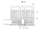
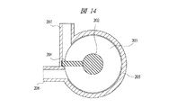
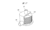
図11は本発明の液冷ジャケットを重ねて更なる性能向上を図った例を示した図、図12は本発明の液冷ジャケットの上部に空冷ヒートシンクおよびファンを重ねて更なる性能向上を図った例を示した図、図13は本発明の液冷ジャケットと一体になった空冷ヒートシンクにより更なる性能向上を図った例を示した図、図14および図15は本発明の液冷ジャケットの冷却液の入口および出口の配置を変えた例を示した図、図16および17は本発明の液冷ジャケットの放熱フィンに螺旋状の放熱フィンを用いた例を示した図である。 FIG. 11 is a diagram showing an example in which the liquid cooling jacket of the present invention is stacked to further improve the performance, and FIG. 12 is a table in which an air cooling heat sink and a fan are stacked on the liquid cooling jacket of the present invention to further improve the performance. FIG. 13 is a diagram showing an example of further improvement in performance by an air-cooled heat sink integrated with the liquid cooling jacket of the present invention, and FIGS. 14 and 15 are diagrams of the liquid cooling jacket of the present invention. FIGS. 16 and 17 are diagrams showing an example in which the arrangement of the inlet and outlet of the cooling liquid is changed, and FIGS. 16 and 17 are diagrams showing an example in which a spiral radiating fin is used as the radiating fin of the liquid cooling jacket of the present invention.
本実施の形態での液冷ジャケットは、発熱体の熱を垂直方向に伝導させるため、図11に示すように、液冷ジャケットの上に更に液冷ジャケットを重ねて熱伝達効率を更に向上させることが可能である。詳しくは、発熱体103の熱を受けた柱202は、ケース205の天板1001と接触しており、熱的に接続されている。従って発熱体103の熱は、矢印1002に示すように上部ジャケットの柱202まで伝わる。これにより、発熱体103の熱は複数のジャケットにより冷却液に伝えられるため、熱伝達効率が更に向上する。
Since the liquid cooling jacket in this embodiment conducts heat of the heating element in the vertical direction, as shown in FIG. 11, the liquid cooling jacket is further stacked on the liquid cooling jacket to further improve the heat transfer efficiency. It is possible. Specifically, the
また、柱202とケース205の天板1001を熱的に接続させることにより、図12に示すように、空冷ヒートシンク1101およびファン1102を取り付けて更なる冷却能力の向上を図ることができる。
Further, by thermally connecting the
更に図13に示すように、柱202は天板1001を貫通し、空冷ヒートシンク1201と一体形状となっていても良い。
Further, as shown in FIG. 13, the
また、液冷ジャケットの入口206および出口207の向きについては、図14および図15に示すように、片側もしくは両側の出入口の方向を変えることもできる。
As for the orientation of the
また、螺旋状の放熱フィンを用いることにより、仕切り204を用いずに冷却液をターンさせることもできる。
Further, by using a spiral radiating fin, the coolant can be turned without using the
これは、図16および図17に示すように、螺旋状の放熱フィン1801を用いることにより、入口206により入ってくる冷却液を螺旋状に流し、上部の出口207から排出するものである。本実施の形態の場合、出口207の位置は、ケース205の上部であれば良く、例えば、図16に示す207’の位置や、図17に示すようにケース205の天面にあっても良い。
As shown in FIGS. 16 and 17, by using a spiral
以上のように、本実施の形態では、発熱体103に接合するベース201と、ベース201に対して垂直に立っている柱202と、柱202に取り付けられ、ベース201と平行に配置された複数の放熱フィン203と、複数の放熱フィン203の間を所定の幅で埋める仕切り204と、柱202および放熱フィン203を囲みベース201と接合し、仕切り204に対して対称となる位置に冷却液の入口206および出口207が取り付けられたケース205とを備え、複数の放熱フィン203は、その厚みに比べて狭い間隔で配置されるようにしているので、液冷ジャケット内部の冷却液流は、複数流路を確保しているため、流路抵抗が低く、かつ冷却液の出入口の大きさは、並んだ放熱フィン203の高さとほぼ同じにすることにより、各放熱フィン203間の流速を均一にすることができる。
As described above, in this embodiment, the
また、各放熱フィン203に熱を伝える柱202は太く、また高さは発熱体103と接触しているベース201から近距離とすることができるため、熱伝導効率が高い。
In addition, since the
また、放熱フィン203間に設けられた仕切り204により冷却液の順路はUターンするので冷却液出入口を並んで配置でき、配管上利便性に優れている。
Further, since the forward path of the coolant is U-turned by the
101…筐体、102…マザーボード、103…CPU(発熱体)、104…チップセット、105…メモリ、106…HDD、107…FDD、108…CD−ROMドライブ、109…電源、113…ファン、201…ベース、202…柱、203…放熱フィン、204…仕切り、205…ケース、206…冷却液入口、207…冷却液出口、209…ヒートパイプ、131…液冷ジャケット、132…ポンプ、133…チューブ、134…金属管、135…液冷システム用ヒートシンク、801…溝、901…溝、1001…ケースの天板、1101…空冷ヒートシンク、1102…ファン、1201…空冷ヒートシンク。
DESCRIPTION OF
Claims (5)
前記ベース部材に対し垂直に設けられ垂直方向に熱を伝える柱状部材と、
前記柱状部材に設けられ前記ベース部材に並行に積層配置される複数の放熱フィンと、
前記ベース部材と接合して前記柱状部材と前記複数の放熱フィンを内包するケース部材と、
前記ケース部材の外周部の周方向に設けられて、前記ケース部材の内部に冷却液を入れる液入口と前記ケース部材から冷却液を排出する液出口と、
前記複数の放熱フィンの間に形成された冷却液の通流する液流路と、
前記液入口と前記液出口との間の前記複数の放熱フィン間に設けられ、前記液入口から前記液出口への流れを形成する仕切り部材と、を備え、
前記放熱フィンの厚みに比べて前記放熱フィン間を狭くし、
冷却液が前記柱状部材を中心に前記液入口から前記液出口に通流するようにしたことを特徴とする液冷ジャケット。 A base member joined to the heating element;
A columnar member that is provided perpendicular to the base member and conducts heat in a vertical direction;
A plurality of heat dissipating fins provided in the columnar member and stacked in parallel with the base member;
A case member that joins the base member and encloses the columnar member and the plurality of radiating fins;
A liquid inlet that is provided in a circumferential direction of the outer peripheral portion of the case member, puts the cooling liquid into the case member, and a liquid outlet that discharges the cooling liquid from the case member;
A liquid flow path through which a cooling liquid is formed between the plurality of radiating fins;
A partition member provided between the plurality of heat radiation fins between the liquid inlet and the liquid outlet, and forming a flow from the liquid inlet to the liquid outlet;
Compared to the thickness of the radiation fins, the space between the radiation fins is narrowed,
A liquid cooling jacket characterized in that cooling liquid flows from the liquid inlet to the liquid outlet around the columnar member.
前記柱状部材は円柱形状であり、
前記放熱フィンは前記柱状部材に対して同心円形状であることを特徴とする液冷ジャケット。 The liquid cooling jacket according to claim 1,
The columnar member is a circular pillar shape,
The liquid cooling jacket, wherein the heat dissipating fins have a concentric shape with respect to the columnar member.
前記液入口と前記液出口の口径は、前記積層配置される複数の放熱フィンの高さに等しいことを特徴とする液冷ジャケット。 The liquid cooling jacket according to claim 1 or 2,
The liquid cooling jacket characterized in that the diameters of the liquid inlet and the liquid outlet are equal to the height of the plurality of heat dissipating fins arranged in a stacked manner.
さらに、前記ケース部材の前記ベース部材と対向する前記ケース部材の上面に設けられた空冷ヒートシンクおよびファンを備え、
前記柱状部材は前記ケース部材の天面に接触し、発熱体の発生熱が前記柱状部材を介して前記空冷ヒートシンクに伝わることを特徴とする液冷ジャケット。 In the liquid cooling jacket according to claim 1, 2, or 3,
Furthermore, an air-cooled heat sink and a fan provided on the upper surface of the case member facing the base member of the case member,
The columnar member is in contact with the top surface of the case member, and heat generated by a heating element is transmitted to the air-cooled heat sink through the columnar member.
前記空冷ヒートシンクは、前記ケース部材を貫通して設けられた前記柱状部材に前記放熱フィンを接続する構成から成ることを特徴とする液冷ジャケット。 The liquid cooling jacket according to claim 4,
The air cooling heat sink has a configuration in which the heat radiation fin is connected to the columnar member provided through the case member.
Priority Applications (6)
| Application Number | Priority Date | Filing Date | Title |
|---|---|---|---|
| JP2003349701A JP3771233B2 (en) | 2003-10-08 | 2003-10-08 | Liquid cooling jacket |
| TW093105571A TWI302242B (en) | 2003-10-08 | 2004-03-03 | Liquid cooling jacket |
| EP04005471A EP1524692A3 (en) | 2003-10-08 | 2004-03-08 | Liquid cooled jacket for an electronic device |
| KR1020040015680A KR100610293B1 (en) | 2003-10-08 | 2004-03-09 | Liquid Cooling Jacket |
| US10/796,045 US7021367B2 (en) | 2003-10-08 | 2004-03-10 | Liquid cooling jacket |
| CNB2004100282502A CN100385653C (en) | 2003-10-08 | 2004-03-10 | Liquid cooling jacket |
Applications Claiming Priority (1)
| Application Number | Priority Date | Filing Date | Title |
|---|---|---|---|
| JP2003349701A JP3771233B2 (en) | 2003-10-08 | 2003-10-08 | Liquid cooling jacket |
Publications (3)
| Publication Number | Publication Date |
|---|---|
| JP2005116815A JP2005116815A (en) | 2005-04-28 |
| JP2005116815A5 JP2005116815A5 (en) | 2005-10-06 |
| JP3771233B2 true JP3771233B2 (en) | 2006-04-26 |
Family
ID=34373532
Family Applications (1)
| Application Number | Title | Priority Date | Filing Date |
|---|---|---|---|
| JP2003349701A Expired - Fee Related JP3771233B2 (en) | 2003-10-08 | 2003-10-08 | Liquid cooling jacket |
Country Status (6)
| Country | Link |
|---|---|
| US (1) | US7021367B2 (en) |
| EP (1) | EP1524692A3 (en) |
| JP (1) | JP3771233B2 (en) |
| KR (1) | KR100610293B1 (en) |
| CN (1) | CN100385653C (en) |
| TW (1) | TWI302242B (en) |
Families Citing this family (44)
| Publication number | Priority date | Publication date | Assignee | Title |
|---|---|---|---|---|
| DE102004012026B3 (en) * | 2004-03-11 | 2005-11-17 | Hüttinger Elektronik GmbH & Co. KG | Arrangement for cooling |
| TWM267825U (en) * | 2004-11-03 | 2005-06-11 | Forward Electronics Co Ltd | Improved heat sink structure of liquid-cooling type heat sink device |
| JP2006286767A (en) * | 2005-03-31 | 2006-10-19 | Hitachi Ltd | Cooling jacket |
| JP4266959B2 (en) * | 2005-06-08 | 2009-05-27 | Necディスプレイソリューションズ株式会社 | Electronic apparatus cooling device and projection optical device |
| CN100499974C (en) * | 2005-08-10 | 2009-06-10 | 富准精密工业(深圳)有限公司 | Integral liquid-cooled radiator |
| JP4593438B2 (en) | 2005-10-24 | 2010-12-08 | 富士通株式会社 | Electronics and cooling modules |
| TWM289878U (en) * | 2005-11-11 | 2006-04-21 | Cooler Master Co Ltd | Heat-dissipation structure of water-cooling type parallel runner |
| US20080310105A1 (en) * | 2007-06-14 | 2008-12-18 | Chia-Chun Cheng | Heat dissipating apparatus and water cooling system having the same |
| KR100886951B1 (en) * | 2007-07-12 | 2009-03-09 | 한국전기연구원 | Cooling apparatus having thermoelectric module |
| US9453691B2 (en) * | 2007-08-09 | 2016-09-27 | Coolit Systems, Inc. | Fluid heat exchange systems |
| US9943014B2 (en) | 2013-03-15 | 2018-04-10 | Coolit Systems, Inc. | Manifolded heat exchangers and related systems |
| US8746330B2 (en) * | 2007-08-09 | 2014-06-10 | Coolit Systems Inc. | Fluid heat exchanger configured to provide a split flow |
| US9496200B2 (en) | 2011-07-27 | 2016-11-15 | Coolit Systems, Inc. | Modular heat-transfer systems |
| TW200910068A (en) * | 2007-08-20 | 2009-03-01 | Asustek Comp Inc | Heat dissipation apparatus |
| JP5341549B2 (en) * | 2009-02-19 | 2013-11-13 | 株式会社ティラド | heatsink |
| US8000101B2 (en) * | 2009-07-23 | 2011-08-16 | Hewlett-Packard Development Company, L.P. | System and method for attaching liquid cooling apparatus to a chassis |
| US9651488B2 (en) * | 2010-10-14 | 2017-05-16 | Thermo Fisher Scientific (Bremen) Gmbh | High-accuracy mid-IR laser-based gas sensor |
| EP2627988A4 (en) | 2010-10-14 | 2017-11-15 | Thermo Fisher Scientific (Bremen) GmbH | Optical chamber module assembly |
| US20120103575A1 (en) * | 2010-11-03 | 2012-05-03 | Hon Hai Precision Industry Co., Ltd. | Cooling device |
| US20120305218A1 (en) * | 2011-06-01 | 2012-12-06 | Benjamin Masefield | Heat Sink |
| CN102819303A (en) * | 2011-06-09 | 2012-12-12 | 鸿富锦精密工业(深圳)有限公司 | Computer case |
| WO2014141162A1 (en) | 2013-03-15 | 2014-09-18 | Coolit Systems, Inc. | Sensors, multiplexed communication techniques, and related systems |
| US10365667B2 (en) | 2011-08-11 | 2019-07-30 | Coolit Systems, Inc. | Flow-path controllers and related systems |
| DE102011052707A1 (en) * | 2011-08-15 | 2013-02-21 | Pierburg Gmbh | Cooling device for a thermally stressed component |
| WO2013047975A1 (en) | 2011-09-26 | 2013-04-04 | Posco Led Company Ltd. | Optical semiconductor-based lighting apparatus |
| TWM424749U (en) * | 2011-10-27 | 2012-03-11 | Enermax Technology Corp | Liquid-cooled heat exchange module improvement |
| US10415597B2 (en) | 2014-10-27 | 2019-09-17 | Coolit Systems, Inc. | Fluid heat exchange systems |
| US9818671B2 (en) * | 2015-02-10 | 2017-11-14 | Dynatron Corporation | Liquid-cooled heat sink for electronic devices |
| US10107303B2 (en) * | 2015-05-22 | 2018-10-23 | Teza Technologies LLC | Fluid cooled server and radiator |
| JP6482955B2 (en) * | 2015-06-02 | 2019-03-13 | 昭和電工株式会社 | Liquid cooling system |
| DE102016204895B4 (en) * | 2016-03-23 | 2020-11-12 | Phoenix Contact E-Mobility Gmbh | Charging connector with a power contact system and charging station for delivering electrical energy to a receiver of electrical energy |
| EP3572726B1 (en) * | 2017-01-18 | 2021-10-13 | Fujian Sanan Sino-Science Photobiotech Co., Ltd. | Easily shaped liquid cooling heat-dissipating module of led lamp |
| CN107425323B (en) * | 2017-08-28 | 2022-07-05 | 深圳市沃尔新能源电气科技股份有限公司 | Female terminal of pegging graft and applied rifle, the rifle socket that charges of this female terminal |
| US10582650B2 (en) * | 2017-10-13 | 2020-03-03 | Arista Networks, Inc. | Power supply with interchangeable fan module |
| JP7041746B2 (en) * | 2017-12-08 | 2022-03-24 | ケーエムダブリュ・インコーポレーテッド | Heat dissipation device for electronic elements |
| KR101990592B1 (en) | 2018-05-28 | 2019-06-18 | 한국기계연구원 | Phase change cooling module and battery pack using the same |
| TWM575882U (en) * | 2018-11-22 | 2019-03-21 | 訊凱國際股份有限公司 | External water cooling device |
| KR102091698B1 (en) | 2019-01-08 | 2020-03-20 | 한국기계연구원 | Phase change cooling device and phase change cooling method |
| US11662037B2 (en) | 2019-01-18 | 2023-05-30 | Coolit Systems, Inc. | Fluid flow control valve for fluid flow systems, and methods |
| US11473860B2 (en) | 2019-04-25 | 2022-10-18 | Coolit Systems, Inc. | Cooling module with leak detector and related systems |
| US10874034B1 (en) * | 2019-11-05 | 2020-12-22 | Facebook, Inc. | Pump driven liquid cooling module with tower fins |
| WO2021229365A1 (en) | 2020-05-11 | 2021-11-18 | Coolit Systems, Inc. | Liquid pumping units, and related systems and methods |
| US11725886B2 (en) | 2021-05-20 | 2023-08-15 | Coolit Systems, Inc. | Modular fluid heat exchange systems |
| CN114485216B (en) * | 2022-01-10 | 2023-06-23 | 中国科学院理化技术研究所 | Radiating fin type heat exchanger and free piston Stirling generator |
Family Cites Families (21)
| Publication number | Priority date | Publication date | Assignee | Title |
|---|---|---|---|---|
| US4188996A (en) * | 1977-05-04 | 1980-02-19 | Ckd Praha, Oborovy Podnik | Liquid cooler for semiconductor power elements |
| JPS55123153A (en) * | 1979-03-16 | 1980-09-22 | Fujitsu Ltd | Semiconductor device |
| US4592415A (en) * | 1984-10-09 | 1986-06-03 | Howard Friedman | Thin flat heat exchanger and method of making same |
| JPS6243054A (en) * | 1985-08-20 | 1987-02-25 | Oki Electric Ind Co Ltd | Vacuum equipment |
| JPS62274798A (en) * | 1986-05-19 | 1987-11-28 | インタ−ナショナル ビジネス マシ−ンズ コ−ポレ−ション | Heatsink structure |
| JP2635914B2 (en) * | 1993-08-18 | 1997-07-30 | カワソーテクセル株式会社 | Liquid-cooled resistor |
| JP2833999B2 (en) * | 1994-07-13 | 1998-12-09 | 日本電気株式会社 | LSI cooling module |
| WO1997008002A1 (en) * | 1995-08-25 | 1997-03-06 | Kabushiki Kaisha Toyoda Jidoshokki Seisakusho | Viscous heater |
| US5763951A (en) * | 1996-07-22 | 1998-06-09 | Northrop Grumman Corporation | Non-mechanical magnetic pump for liquid cooling |
| US6167948B1 (en) * | 1996-11-18 | 2001-01-02 | Novel Concepts, Inc. | Thin, planar heat spreader |
| EP0889524A3 (en) * | 1997-06-30 | 1999-03-03 | Sun Microsystems, Inc. | Scalable and modular heat sink-heat pipe cooling system |
| JPH11121667A (en) * | 1997-10-20 | 1999-04-30 | Fujitsu Ltd | Heat pipe type cooling device |
| JP2000340727A (en) | 1999-05-26 | 2000-12-08 | Nissan Motor Co Ltd | Cooling structure of electronic component |
| US6199625B1 (en) * | 1999-06-11 | 2001-03-13 | Psc Computer Products, Inc. | Stackable heat sink for electronic components |
| US6796370B1 (en) * | 2000-11-03 | 2004-09-28 | Cray Inc. | Semiconductor circular and radial flow cooler |
| JP4634599B2 (en) | 2000-11-30 | 2011-02-16 | 株式会社ティラド | Water cooling heat sink |
| DE20111305U1 (en) * | 2001-07-11 | 2002-01-31 | Innovatek Os Gmbh | Water cooling system for cooling CPU's including bracket |
| US6707676B1 (en) * | 2002-08-30 | 2004-03-16 | Ehood Geva | Heat sink for automatic assembling |
| US6712128B1 (en) * | 2002-11-20 | 2004-03-30 | Thermal Corp. | Cylindrical fin tower heat sink and heat exchanger |
| DE20302201U1 (en) * | 2003-02-12 | 2003-04-24 | Wille Stephan | Cooling system for semiconductors has flow passage formed to provide uniform effect |
| US6793009B1 (en) * | 2003-06-10 | 2004-09-21 | Thermal Corp. | CTE-matched heat pipe |
-
2003
- 2003-10-08 JP JP2003349701A patent/JP3771233B2/en not_active Expired - Fee Related
-
2004
- 2004-03-03 TW TW093105571A patent/TWI302242B/en not_active IP Right Cessation
- 2004-03-08 EP EP04005471A patent/EP1524692A3/en not_active Withdrawn
- 2004-03-09 KR KR1020040015680A patent/KR100610293B1/en active IP Right Grant
- 2004-03-10 US US10/796,045 patent/US7021367B2/en not_active Expired - Lifetime
- 2004-03-10 CN CNB2004100282502A patent/CN100385653C/en not_active Expired - Fee Related
Also Published As
| Publication number | Publication date |
|---|---|
| EP1524692A3 (en) | 2009-12-23 |
| TWI302242B (en) | 2008-10-21 |
| US20050077028A1 (en) | 2005-04-14 |
| KR100610293B1 (en) | 2006-08-09 |
| CN100385653C (en) | 2008-04-30 |
| CN1606403A (en) | 2005-04-13 |
| KR20050034526A (en) | 2005-04-14 |
| US7021367B2 (en) | 2006-04-04 |
| EP1524692A2 (en) | 2005-04-20 |
| TW200513832A (en) | 2005-04-16 |
| JP2005116815A (en) | 2005-04-28 |
Similar Documents
| Publication | Publication Date | Title |
|---|---|---|
| JP3771233B2 (en) | Liquid cooling jacket | |
| JP5117101B2 (en) | Evaporator and circulating cooling device using the same | |
| US6966359B1 (en) | Radiator plate rapid cooling apparatus | |
| EP1708263B1 (en) | Cooling jacket | |
| US7911791B2 (en) | Heat sink for a circuit device | |
| EP1710660A2 (en) | Cooling system for an electronic system | |
| JP2009532871A (en) | Cooling system | |
| JP3851875B2 (en) | Cooling device and electronic equipment | |
| JP2005229033A (en) | Liquid-cooled system and electronic apparatus having the same | |
| US20050007730A1 (en) | Electronic apparatus | |
| US20080216991A1 (en) | Cooling device for information equipment | |
| US11137175B2 (en) | Composite water-cooling radiator structure | |
| US20070097637A1 (en) | Heat dissipation device | |
| JP2004295718A (en) | Liquid cooling system for information processor | |
| US10607918B2 (en) | Phase-change cooler and phase-change cooling method | |
| TWM586876U (en) | Composite water-cooled drain structure | |
| JP5689511B2 (en) | Cold plate | |
| JP4697171B2 (en) | COOLING DEVICE AND ELECTRONIC DEVICE HAVING THE SAME | |
| JP5614239B2 (en) | Circuit module | |
| JP2006229102A (en) | Boiling cooler | |
| JP2005221191A (en) | Heat exchanger for electronic apparatus | |
| JP2008089253A (en) | Heat sink | |
| JP2009088051A (en) | Cooling device for electronic instrument | |
| TWI715094B (en) | Composite water-cooling radiator structure | |
| CN210136472U (en) | Composite water cooling drainage structure |
Legal Events
| Date | Code | Title | Description |
|---|---|---|---|
| A521 | Request for written amendment filed |
Free format text: JAPANESE INTERMEDIATE CODE: A523 Effective date: 20050804 |
|
| A621 | Written request for application examination |
Free format text: JAPANESE INTERMEDIATE CODE: A621 Effective date: 20050804 |
|
| A871 | Explanation of circumstances concerning accelerated examination |
Free format text: JAPANESE INTERMEDIATE CODE: A871 Effective date: 20050804 |
|
| A975 | Report on accelerated examination |
Free format text: JAPANESE INTERMEDIATE CODE: A971005 Effective date: 20050818 |
|
| A977 | Report on retrieval |
Free format text: JAPANESE INTERMEDIATE CODE: A971007 Effective date: 20051014 |
|
| A131 | Notification of reasons for refusal |
Free format text: JAPANESE INTERMEDIATE CODE: A131 Effective date: 20051101 |
|
| A521 | Request for written amendment filed |
Free format text: JAPANESE INTERMEDIATE CODE: A523 Effective date: 20051220 |
|
| TRDD | Decision of grant or rejection written | ||
| A01 | Written decision to grant a patent or to grant a registration (utility model) |
Free format text: JAPANESE INTERMEDIATE CODE: A01 Effective date: 20060117 |
|
| A61 | First payment of annual fees (during grant procedure) |
Free format text: JAPANESE INTERMEDIATE CODE: A61 Effective date: 20060208 |
|
| R150 | Certificate of patent or registration of utility model |
Ref document number: 3771233 Country of ref document: JP Free format text: JAPANESE INTERMEDIATE CODE: R150 Free format text: JAPANESE INTERMEDIATE CODE: R150 |
|
| FPAY | Renewal fee payment (event date is renewal date of database) |
Free format text: PAYMENT UNTIL: 20090217 Year of fee payment: 3 |
|
| FPAY | Renewal fee payment (event date is renewal date of database) |
Free format text: PAYMENT UNTIL: 20100217 Year of fee payment: 4 |
|
| FPAY | Renewal fee payment (event date is renewal date of database) |
Free format text: PAYMENT UNTIL: 20100217 Year of fee payment: 4 |
|
| FPAY | Renewal fee payment (event date is renewal date of database) |
Free format text: PAYMENT UNTIL: 20110217 Year of fee payment: 5 |
|
| FPAY | Renewal fee payment (event date is renewal date of database) |
Free format text: PAYMENT UNTIL: 20120217 Year of fee payment: 6 |
|
| FPAY | Renewal fee payment (event date is renewal date of database) |
Free format text: PAYMENT UNTIL: 20120217 Year of fee payment: 6 |
|
| FPAY | Renewal fee payment (event date is renewal date of database) |
Free format text: PAYMENT UNTIL: 20130217 Year of fee payment: 7 |
|
| FPAY | Renewal fee payment (event date is renewal date of database) |
Free format text: PAYMENT UNTIL: 20130217 Year of fee payment: 7 |
|
| S111 | Request for change of ownership or part of ownership |
Free format text: JAPANESE INTERMEDIATE CODE: R313111 |
|
| R350 | Written notification of registration of transfer |
Free format text: JAPANESE INTERMEDIATE CODE: R350 |
|
| S111 | Request for change of ownership or part of ownership |
Free format text: JAPANESE INTERMEDIATE CODE: R313111 |
|
| R350 | Written notification of registration of transfer |
Free format text: JAPANESE INTERMEDIATE CODE: R350 |
|
| R250 | Receipt of annual fees |
Free format text: JAPANESE INTERMEDIATE CODE: R250 |
|
| R250 | Receipt of annual fees |
Free format text: JAPANESE INTERMEDIATE CODE: R250 |
|
| R250 | Receipt of annual fees |
Free format text: JAPANESE INTERMEDIATE CODE: R250 |
|
| S111 | Request for change of ownership or part of ownership |
Free format text: JAPANESE INTERMEDIATE CODE: R313111 |
|
| R350 | Written notification of registration of transfer |
Free format text: JAPANESE INTERMEDIATE CODE: R350 |
|
| LAPS | Cancellation because of no payment of annual fees |