JP3765166B2 - Vehicle interior member having airbag door - Google Patents
Vehicle interior member having airbag door Download PDFInfo
- Publication number
- JP3765166B2 JP3765166B2 JP20323797A JP20323797A JP3765166B2 JP 3765166 B2 JP3765166 B2 JP 3765166B2 JP 20323797 A JP20323797 A JP 20323797A JP 20323797 A JP20323797 A JP 20323797A JP 3765166 B2 JP3765166 B2 JP 3765166B2
- Authority
- JP
- Japan
- Prior art keywords
- airbag
- airbag door
- door portion
- tier
- metal plate
- Prior art date
- Legal status (The legal status is an assumption and is not a legal conclusion. Google has not performed a legal analysis and makes no representation as to the accuracy of the status listed.)
- Expired - Fee Related
Links
Images


Landscapes
- Air Bags (AREA)
- Instrument Panels (AREA)
Description
【0001】
【発明の属する技術分野】
本発明はエアバッグ装置のドア部を車両用内装部材に設けたエアバッグドア部を有する車両用内装部材に関する。
【0002】
【従来の技術】
従来からエアバッグドア部を有するインストルメントパネル、ドアトリム、センタピラー等の車両用内装部材が知られており、その一例が特開平8−192666号公報に示されている。
【0003】
この公報に開示されているエアバッグドア部を有するインストルメントパネルでは、エアバッグドア用の開口部を有するインストルメントパネルの本体部を熱可塑性樹脂で射出成形した後に、エアバッグドア部(開口部)を熱可塑性エラストマーで射出成形する、所謂2色成形(ダブルインジェクション成形)によって、インストルメントパネルの本体部とエアバッグドア部とが一体成形されている。また、一般に知られた構造として、別体のエアバッグドア(熱可塑性エラストマーで射出成形したもの)を後付けしたインストルメントパネルがある。
【0004】
【発明が解決しようとする課題】
しかしながら、このようなエアバッグドア部を有するインストルメントパネルにおいて、エアバッグドア部の樹脂を本体部の樹脂と変えることなく、インストルメントパネル全体を同一樹脂で構成した場合には、本体部の樹脂の特性上、本体部の樹脂の弾性率がエアバッグドア部の樹脂(TPO)の弾性率に対し6〜7倍、引張強度で1.5〜2倍と高いため、エアバッグドア部に形成される展開時の、例えばH形破断部(ティア部)の破断力が同一厚みでは高くなり、エアバッグドア部が展開し難くなると共に、ヒンジ部が展開時に破損することもある。これを改善するために、破断部の樹脂厚を薄くし過ぎると、成形時の欠肉、ベコツキや変形が発生する。特に、硬質樹脂インストルメントパネルでは、ウエルドヒケ、うねり等によって意匠面側から薄肉部周辺に凹凸が見えるため、外観品質が低下する。
【0005】
また、意匠面側から破断部のライン及びエアバッグドア部の外周が全く見えない(インビジブルタイプ)状態にするには、破断部を成形時に厚肉にし、後加工によってカットする方法がある。しかし、この方法では所定の破断力を維持した上で破断部のラインが見えないようにすることは甚だ困難である。即ち、樹脂厚を小さくすると、レリーフ溝を施したとしても、破断部のラインやうねり感が、意匠面側から見えてしまい、意匠上の外観品質を保持できず、樹脂厚を十分に小さくすることができない。
【0006】
なお、エアバッグドア部に形成される展開時の破断部(ティア部)の破断力が高くなり、エアバッグドア部が展開し難くなり、これを改善するために、破断部の樹脂厚を薄くし過ぎると、意匠面側から薄肉部が見えるため、外観品質が低下するという不具合は、エアバッグドア部とインストルメントパネルの本体部とを異なる樹脂を用いて2色成形にて一体成形したインストルメントパネルや、エアバッグドア部とインストルメントパネルの本体部とを別々に成形した後に係止爪やビス等によって一体としたインストルメントパネルの破断部においても発生する。
【0007】
本発明は上記事実を考慮し、車両用内装部材のエアバッグドア部と本体部とを同一樹脂で成形した場合にも、外観品質が低下することなく、且つエアバッグドア部の破断部の破断力を所望の値に下げることができるエアバッグドア部を有する車両用内装部材を得ることが目的である。
【0008】
【0009】
【0010】
【0011】
【0012】
【0013】
【0014】
【課題を解決するための手段】
請求項1記載の本発明は、エアバッグドア部と本体部とが、同一の硬質樹脂材料で一体成形または別体とされたエアバッグドア部を有する車両用内装部材であって、
前記エアバッグドア部に形成したティア部と、
エアバッグ袋体展開時に前記ティア部の中央部を挟む前記エアバッグドア部の両側もしくは片側の部位を突き上げる突き上げ手段と、
を有し、
前記突き上げ手段は、前記エアバッグドア部と分離されており、且つ前記エアバッグドア部の下方に配設され前記エアバッグドア部の下面との間に隙間が設定されており、エアバッグ袋体展開時に前記ティア部の中央部を挟んで、前記エアバッグドア部の両側もしくは片側の部位に当接する先端部の下面と上面とのうちの少なくとも一方に突起を備えた金属板であることを特徴としている。
【0015】
従って、エアバッグ袋体展開時にエアバッグ袋体からの衝撃荷重が、エアバッグドア部と分離されており、且つエアバッグドア部の下方に配設されエアバッグドア部の下面との間に隙間が設定された金属板の先端部によりティア部の中央部に集中して作用し、ティア部の中央部からスムーズに破断する。この結果、外観品質と展開性能の両立を図ることができる。また、金属板を使用することで、従来の車両用内装部材に適用できる。
【0016】
請求項2記載の本発明は、エアバッグドア部と本体部とが、同一の硬質樹脂材料で一体成形または別体とされたエアバッグドア部を有する車両用内装部材であって、
前記エアバッグドア部に形成したティア部と、
エアバッグ袋体展開時に前記ティア部の中央部を挟む前記エアバッグドア部の両側もしくは片側の部位を突き上げる突き上げ手段と、
を有し、
前記突き上げ手段は、前記エアバッグドア部と分離されており、且つ前記エアバッグドア部の下方に配設され前記エアバッグドア部の下面との間に隙間が設定されており、エアバッグ袋体展開時に前記ティア部の中央部を挟んで、前記エアバッグドア部の両側もしくは片側の部位に当接する先端部の上面に幅狭の突起を備えた金属板であることを特徴としている。
【0017】
従って、エアバッグ袋体展開時にエアバッグ袋体からの衝撃荷重が、エアバッグドア部と分離されており、且つエアバッグドア部の下方に配設されエアバッグドア部の下面との間に隙間が設定された金属板の突起によりティア部の中央部に集中して作用し、ティア部の中央部からスムーズに破断する。この時、金属板の先端部の上面に幅狭の突起を設けたことによって、展開初期時においてエアバッグ袋体の上面が凹凸形状となっていても、確実にティア部の中央部から破断させることが可能になる。
【0018】
請求項3記載の本発明は、エアバッグドア部と本体部とが、同一の硬質樹脂材料で一体成形または別体とされたエアバッグドア部を有する車両用内装部材であって、
前記エアバッグドア部に形成したティア部と、
エアバッグ袋体展開時に前記ティア部の中央部を挟む前記エアバッグドア部の両側もしくは片側の部位を突き上げる突き上げ手段と、
を有し、
前記突き上げ手段は、前記エアバッグドア部と分離されており、且つ前記エアバッグドア部の下方に配設され前記エアバッグドア部の下面との間に隙間が設定されており、エアバッグ袋体展開時に前記ティア部の中央部を挟んで、前記エアバッグドア部の両側もしくは片側の部位に当接する先端部を備えた金属板であって、前記金属板のヒンジ部が前記エアバッグドア部のヒンジ部よりも前記ティア部側にオフセットされていると共に、前記金属板のヒンジ部に対して前記金属板の固定部と前記金属板のヒンジ部よりティア部側の部位が高剛性となっていることを特徴としている。
【0019】
従って、エアバッグ袋体展開時にエアバッグ袋体からの衝撃荷重が、エアバッグドア部と分離されており、且つエアバッグドア部の下方に配設されエアバッグドア部の下面との間に隙間が設定された金属板の先端部によりティア部の中央部に集中して作用し、ティア部の中央部からスムーズに破断する。この結果、外観品質と展開性能の両立を図ることができる。また、金属板によりエアバッグ袋体展開時に、エアバッグ袋体がエアバッグドア部のヒンジ部に直接当接することを防止できるので、エアバッグ袋体によるエアバッグドア部のヒンジ部の破損を防止できる。
【0020】
【0021】
【0022】
【0023】
【0024】
【0025】
【0026】
【0027】
【0028】
【0029】
【0030】
【0031】
【0032】
【0033】
【0034】
【0035】
【0036】
【0037】
【発明の実施の形態】
本発明のエアバッグドア部を有する車両用内装部材の第1実施形態を図1〜図4に従って説明する。
【0038】
なお、図中矢印FRは車両前方方向を、矢印UPは車両上方方向を示す。
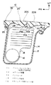
図1に示される如く、車両の車室内に設けられている車両用内装部材としてのいインストルメントパネル10には、助手席側の内方にエアバッグ装置12が配設されている。このエアバッグ装置12のエアバッグケース14は、図示を省略したインストルメントパネル・リインフォースメントに固定されており、エアバッグケース14内には、インフレータ16及び折り畳んだ状態でエアバッグ袋体18が収納されている。
【0039】
また、インストルメントパネル10のエアバッグケース14と略対向する部位はエアバッグドア部20となっており、インストルメントパネル10のエアバッグドア部20以外の部位は本体部22となっている。これらのエアバッグドア部20と本体部22は、硬質樹脂としてのTSOP[エラストマー(ゴム)とPP(ポリプロピレン)をブロイ化(相乗効果が期待できる高分子多成分系材料を造る技術)し、さらにタルクを加えて複合強化したもので、耐衝撃性と剛性を有し、流動性が良く薄肉製品に適した低比重PP樹脂、例えば、曲げ弾性率1500〜3000MPa]やPP系樹脂、PC/ABS系樹脂、変性PPO系樹脂、PC/PBT系樹脂、ABS系樹脂、PC系樹脂、ASG系樹脂、TPO系樹脂、TPE系樹脂、TPU系樹脂、PC/変性PS系樹脂等で構成されている。
【0040】
エアバッグ装置12は、図示しない機械的又は電気的な加速度センサ等によって車両の急減速を検出すると、エアバッグケース14内のインフレータ16が作動して、エアバッグケース14内に折り畳まれて収容されているエアバッグ袋体18をインストルメントパネル10のエアバッグドア部20へ向けて膨張させる。エアバッグ袋体18は、インストルメントパネル10のエアバッグドア部20を押圧してエアバッグドア部20を開裂させ車室内に展開するようになっている。なお、エアバッグ装置12としては、従来公知の一般的構成を適用できるため、本実施形態ではエアバッグ装置12の詳細な説明は省略する。
【0041】
図3に示される如く、エアバッグドア部20の前後方向略中央部と左右方向両端部には、薄肉とされたティア部24が平面視でH形状に形成されており、エアバッグ袋体展開時にエアバッグドア部20が前後に両開きしてエアバッグ袋体が車室内に展開する構成となっている。
【0042】
図2に示される如く、エアバッグドア部20のティア部24の断面はV字状となっている。また、エアバッグドア部20には、ティア部24の中央部24Aを挟む車両前後方向両側の部位に突き上げ手段としての突起28、30が下方へ向けて突出されており、これらの突起28、30は、エアバッグドア部20と一体成形されている。このため、エアバッグ袋体展開時には、展開するエアバッグ袋体が、突起28、30の下面28A、30Aに当接して、突起28、30を上方(図2の矢印A方向)に押圧するようになっている。
【0043】
図4に示される如く、突起28、30は車両前後方向に延びる幅狭のリブ32と車幅方向に延びる幅狭のリブ34とで格子状に形成されている。これらのリブ32、34の幅T1は、図2に示すエアバッグドア部20の肉厚Tの1/2以下に設定されており、ヒケを防止するようになっている。
【0044】
また、突起28、30の幅W1と長さL1は、図3に示すエアバッグドア部20の前方ドア部20Aと後方ドア部20Bの各全幅Wと全長Lの5%〜20%程度にそれぞれ設定されている。このため、エアバッグドア部20は、突起28、30により幅方向、及び長さ方向への撓みが、極端に損なわれることがなく、エアバッグ袋体展開時にエアバッグドア部20が幅方向、及び長さ方向へ撓むことによって、ティア部24の中央部24Aから確実に破断するようになっている。
【0045】
なお、図1に示される如く、エアバッグドア部20の前後方向両端部には、薄肉とされたヒンジ部26が形成されている。従って、エアバッグドア部20は、エアバッグ展開時、膨張するエアバッグ袋体18によって押圧されると、ティア部24に沿って開裂し、開裂した前方ドア部20Aと後方ドア部20Bとが、ヒンジ部26を中心に回動して、エアバッグ袋体18を車室内へ展開可能とする開口が形成されるようになっている。
【0046】
なお、図2及び図4に示される如く、エアバッグ袋体展開時にエアバッグ袋体18と当接する突起28、30の各角部28B、30B、28C、30C、28D、30D、28E、30Eは、面取りされており、エアバッグ袋体18を保護するようになっている。
【0047】
次に、本発明の第1実施形態の作用を説明する。
本第1実施形態では、エアバッグ袋体展開時に、展開するエアバッグ袋体18が、突起28、30の下面28A、30Aに当接して、突起28、30を上方(図2の矢印A方向)押圧する。このため、エアバッグ袋体18から瞬間的に衝撃荷重が突起28、30に作用し、ティア部24の中央部24Aからスムーズに破断する。この結果、ティア部24の板厚が厚くても容易に破断させることができるため、展開性能と外観品質(インビジブル化)との両立を図ることが可能である。
【0048】
また、ヒンジ部26の負担を軽減できる。さらに、エアバッグドア部20を剛性の高い硬質材料で構成できるので、べこつき感や変形も防止できる。また、エアバッグドア部20に突起28、30を設けるだけの簡単な構成で外観品質と展開性能の両立を図ることが可能である。
【0049】
さらに、突起28、30をエアバッグドア部20と一体成形されているリブ32とリブ34とで形成したため、別部品を装着する必要がなく突起28、30を形成できると共に、リブ32とリブ34の幅(T1)が、エアバッグドア部20の一般部の厚さ(T)より狭い(T1≦T/2)ため、射出成形後にエアバッグドア部20の表面に、リブ32、34によるヒケが発生することを抑制できるので、外観品質の悪化を招くこともない。
【0050】
なお、本第1実施形態では、図4に示される如く、突起28、30を車両前後方向に延びる幅狭のリブ32と車幅方向に延びる幅狭のリブ34とで格子状に形成したが、突起28、30の形状は、これに限定されず、例えば、図5に示される如く、E字状等の他の形状にしても良い。
【0051】
また、本第1実施形態では、図3に示される如く、ティア部24を平面視でH形状に形成したが、ティア部24の形状はこれに限定されず、例えば、図6(A)に示される如く直線形状、図6(B)に示される如くY字を2個重ねた形状、図6(C)に示される如くX字形状等の他の形状でも良い。また、図6(D)に示される如く、ティア部24がX字形状である場合には、車幅方向においてもティア部24を挟んで突起29、31を形成しても良い。また、図6(E)に示される如く、ティア部24がコ字形状である場合には、ティア部24の片側に突起28のみを形成しても良い。
【0052】
次に、本発明のエアバッグドア部を有する車両用内装部材の第2実施形態を図7〜図9に従って説明する。
【0053】
なお、第1実施形態と同一部材については同一符号を付してその説明を省略する。
【0054】
図7に示される如く、本第2実施形態では、エアバッグドア部20の前方ドア部20Aと後方ドア部20Bの下方にそれぞれ例えばアルミニウム、鉄、ステンレス等の金属からなる金属板36、38が配設されている。金属板36の前端部36Aは、金属板36に穿設された取付孔39を貫通するボルト40によってエアバッグケース14とインストルメントパネル10の本体部22に共締めされている。金属板38の後端部38Aは、金属板38に穿設された取付孔41を貫通するボルト42によってエアバッグケース14とインストルメントパネル10の本体部22に共締めされている。また、金属板36の後側先端部36Bと、金属板38の前側先端部38Bは、それぞれ下方側に向けて断面矩形状に屈曲され、突き上げ手段としての突起44、46となっており、これらの突起44、46は、それぞれエアバッグ袋体展開時にティア部24の中央部24Aを挟んだエアバッグドア部20の前後両側の部位に当接するようになっている。
【0055】
図9に示される如く、平面視において金属板36は後部が狭幅となった台形状とされており、金属板38は前部が狭幅となった台形状とされている。また、突起44、46の幅W2と長さL2は、図3に示すエアバッグドア部20の前方ドア部20Aと後方ドア部20Bの各全幅Wと全長Lの5%〜20%程度にそれぞれ設定されている。このため、エアバッグドア部20は、突起44、46により幅方向、及び長さ方向への撓みが、極端に損なわれることがなく、エアバッグ袋体展開時にエアバッグドア部20が幅方向、及び長さ方向へ撓むことによって、ティア部24の中央部24Aから確実に破断するようになっている。
【0056】
次に、本第2実施形態の作用を説明する。
本第2実施形態では、エアバッグ袋体展開時に、図8に示される如く、展開するエアバッグ袋体18が、金属板36、38の突起44、46の下面44A、46Aに当接して、突起44、46を上方(図8の矢印A方向)押圧する。このため、エアバッグ袋体18から瞬間的に衝撃荷重が突起44、46を介してエアバッグドア部20のティア部24の中央部24Aの前後両側に作用する。このため、エアバッグドア部20は、ティア部24の中央部24Aからスムーズに破断する。この結果、ティア部24の板厚が厚くても容易に破断させることができるため、展開性能と外観品質(インビジブル化)との両立を図ることが可能である。
【0057】
なお、本第2実施形態では、金属板36、38の下面側、即ちエアバッグ袋体18側に突起44、46を形成したが、これに代えて、図10に示される如く、金属板36、38の上面側、即ちエアバッグドア部20側に突起44、46を形成しても良い。この場合には、金属板36、38の先端部36B、38Bの上面に突起44、46を設けたことによって、図10に示される如く、展開初期時においてエアバッグ袋体18の上面18Aが凹凸形状となっていても、平面とされた金属板36、38の各下面にエアバッグ袋体18が確実に当接して、突起44、46を矢印A方向へ押し上げるため、確実にティア部24の中央部24Aから破断させることが可能になる。また、図11に示される如く、金属板36、38の上面側、即ちエアバッグドア部20側に突起44、46を形成する場合には、金属板36、38の平面視形状を矩形状としても、突起44、46をエアバッグドア部のティア部の中央部を挟む車両前後方向両側の部位に確実に当接させることができる。また、本第2実施形態では、金属板36、38にヒンジ部を特に形成していないが、エアバッグドア部20のヒンジ部26と略対向する部位において、金属板36、38を上方または下方に向けてU字状に屈曲させ、ヒンジ部としても良い。
【0058】
次に、本発明のエアバッグドア部を有する車両用内装部材の第3実施形態を図12及び図13に従って説明する。
【0059】
なお、第1実施形態と同一部材については同一符号を付してその説明を省略する。
【0060】
図12に示される如く、本第3実施形態では、エアバッグドア部20の前方ドア部20Aと後方ドア部20Bの下方にそれぞれ例えばアルミニウム、鉄、ステンレス等の金属からなる金属板48、50が配設されている。金属板48の前端部48Aは、ボルト51とナット52によってエアバッグケース14に固定されており、金属板50の後端部50Aは、ボルト53とナット54によってエアバッグケース14に固定されている。また、金属板48、50のヒンジ部48B、50Bは、薄肉厚とされている。これらのヒンジ部48B、50Bは、エアバッグドア部20のヒンジ部26に対して下方向へオフセットしている(オフセット量H1、H2)と共に、ティア部24の中央部24A側にオフセットしている(オフセット量K1、K2)。また、金属板48、50の、ヒンジ部48B、50Bと取付部となっている前端部48A、後端部50Aとの間の部位及びヒンジ部48B、50Bと先端部48C、50Cとの間の部位が、ヒンジ部48B、50Bに比べて高剛性となっている。即ち、ヒンジ部48B、50Bのみが薄肉厚とされて低剛性となっている。
【0061】
次に、本第3実施形態の作用を説明する。
本第3実施形態では、エアバッグ袋体展開時に、図13に示される如く、展開するエアバッグ袋体18が、金属板48、50の下面に当接して、金属板48、50の先端部48C、50Cを上方(図13の矢印A方向)押圧する。このため、エアバッグ袋体18から瞬間的に衝撃荷重が金属板48、50の高剛性である先端部48C、50Cを介してエアバッグドア部20のティア部24の中央部24Aの前後両側に作用するので、エアバッグドア部20は、ティア部24の中央部24Aからスムーズに破断する。この結果、ティア部24の板厚が厚くても容易に破断させることができるため、展開性能と外観品質(インビジブル化)との両立を図ることが可能である。
【0062】
また、金属板48、50のヒンジ部48B、50Bがエアバッグドア部20のヒンジ部26よりもティア部24の中央部24A側にオフセットしており、且つ金属板48、50のヒンジ部48B、50Bと取付部となっている前端部48A、後端部50Aとの間の部位が高剛性となっているため、金属板48、50のヒンジ部48B、50Bと前端部48A、後端部50Aとの間の部位によりエアバッグ袋体展開時に、エアバッグ袋体18がエアバッグドア部20のヒンジ部26に直接当接することを防止できるので、エアバッグ袋体18によるエアバッグドア部20のヒンジ部26の割れ等の破損を防止できる。
【0063】
なお、本第3実施形態では、金属板48、50のヒンジ部48B、50Bを、薄肉厚としたが、これに代えて、図14に示される如く、金属板48、50のヒンジ部48B、50Bは、金属板48、50を上方に向けてU字状に屈曲させる等の他の構成としても良い。
【0064】
次に、本発明のエアバッグドア部を有する車両用内装部材の第4実施形態を図15に従って説明する。
【0065】
なお、第3実施形態と同一部材については同一符号を付してその説明を省略する。
【0066】
図15に示される如く、本第4実施形態では、エアバッグドア部20の前方ドア部20Aと後方ドア部20Bの下方にそれぞれ例えばアルミニウム、鉄、ステンレス等の金属からなる破断力の高いドアヒンジ部保護板56、58が配設されている。ドアヒンジ部保護板56の前部56Aは、ボルト51とナット52によってエアバッグケース14に固定されており、ドアヒンジ部保護板58の後部58Aは、ボルト53とナット54によってエアバッグケース14に固定されている。また、ドアヒンジ部保護板56の後部56Bとドアヒンジ部保護板58の前部58Bは、それぞれエアバッグドア部20のヒンジ部26よりもティア部24の中央部24A側に突出しており、さらに、エアバッグドア部20の裏面に近接する位置まで延長されている。なお、ドアヒンジ部保護板56の後部56Bとドアヒンジ部保護板58の前部58Bとの各延長部は、エアバッグ袋体18からの衝撃荷重によりある程度、塑性変形しても良い構成となっている。
【0067】
次に、本第4実施形態の作用を説明する。
本第4実施形態では、ドアヒンジ部保護板56、58の後部56Bと前部58Bがそれぞれエアバッグドア部20のヒンジ部26よりもティア部24の中央部24A側に突出し、さらに、エアバッグドア部20の裏面に近接する位置まで延長されているため、エアバッグ袋体展開時に、エアバッグ袋体18がエアバッグドア部20のヒンジ部26に直接当接することを防止できるので、エアバッグ袋体18によるヒンジ部26の破損を防止できる。また、エアバッグドア部20のヒンジ部26を保護できるので、相対的に低強度のティア部14の中央部24Aから破断し易くなる。
【0068】
次に、本発明のエアバッグドア部を有する車両用内装部材の第5実施形態を図16に従って説明する。
【0069】
なお、第1実施形態と同一部材については同一符号を付してその説明を省略する。
【0070】
図16に示される如く、本第5実施形態では、エアバッグドア部の基材としてのエアバッグドア部20と、本体部の基材としての本体部22とが同一の硬質樹脂材料で一体成形されており、この一体成形された基材60の表面(意匠面)には、インサート成形または貼り込み成形より例えば、PVC、TPO、ファブリック等から成る表皮62が配設されている。なお、表皮62の裏面(基材)側、或いは表面側には、基材のティア部24に沿って、例えば、薄肉加工されたティア部64が形成されており、表皮62は基材60の表面(意匠面)を覆っている。
【0071】
次に、本第5実施形態の作用を説明する。
本第5実施形態では、エアバッグ袋体展開時に、展開するエアバッグ袋体18が、突起28、30の下面28A、30Aに当接して、突起28、30を上方押圧する。このため、エアバッグ袋体18から瞬間的に衝撃荷重が突起28、30に作用し、ティア部24の中央部24Aからスムーズに破断すると共に、表皮62もティア部60からスムーズに破断する。この結果、ティア部24の板厚が厚くても容易に破断させることができるため、展開性能と外観品質(インビジブル化)との両立を図ることが可能である。
【0072】
また、ヒンジ部26の負担を軽減できる。さらに、エアバッグドア部20を剛性の高い硬質材料で構成できるので、べこつき感や変形も防止できる。また、エアバッグドア部20に突起28、30を設けるだけの簡単な構成で、展開性能と表皮62に転写される外観品質低下(基材のウエルドヒケやうねり状凹凸)の抑制を両立させることができる。さらに、2色成形に比べ複雑な型構造を必要とせず、基材60のティア部24の後加工も不要である。
【0073】
なお、表皮インサート成形の場合、図17(A)に示される単層の表皮62以外に、図17(B)に示される2層の表皮62、図17(C)に示される3層の表皮62を使用しても良い。
【0074】
また、貼り込み成形の場合、図18(A)に示される単層の表皮62以外に、図18(B)に示されるフォーム層63付きの表皮62を使用しても良い。
【0075】
次に、本発明のエアバッグドア部を有する車両用内装部材の第6実施形態を図19に従って説明する。
【0076】
なお、第5実施形態と同一部材については同一符号を付してその説明を省略する。
【0077】
図19に示される如く、本第6実施形態では、基材60と表皮62との間に、例えば、ウレタンフォームから成る発泡層70が一体発泡されている。
【0078】
次に、本第6実施形態の作用を説明する。
本第6実施形態では、エアバッグ袋体展開時に、展開するエアバッグ袋体18が、突起28、30の下面28A、30Aに当接して、突起28、30を上方押圧する。このため、エアバッグ袋体18から瞬間的に衝撃荷重が突起28、30に作用し、ティア部24の中央部24Aからスムーズに破断すると共に、発泡層70と表皮62もスムーズに破断する。この結果、ティア部24の板厚が厚くても容易に破断させることができるため、展開性能と外観品質(インビジブル化)との両立を図ることが可能である。
また、ヒンジ部26の負担を軽減できる。さらに、エアバッグドア部20を剛性の高い硬質材料で構成できるので、べこつき感や変形も防止できる。また、エアバッグドア部20に突起28、30を設けるだけの簡単な構成で、展開性能と表皮62に転写される外観品質低下(基材のウエルドヒケやうねり状凹凸)の抑制を両立させることができる。さらに、従来の一体発泡タイプに比べ補強鉄板及び別体ドア基材の締結部品が不要となると共に、締結作業も不要となる。
【0079】
【0080】
【0081】
【0082】
【0083】
【0084】
【0085】
【0086】
【0087】
【0088】
【0089】
【0090】
以上に於いては、本発明を特定の実施形態について詳細に説明したが、本発明はかかる実施形態に限定されるものではなく、本発明の範囲内にて他の種々の実施形態が可能であることは明らかである。例えば、ティア部24の断面形状は、V字形状の他にU字状等の他の形状にしても良い。
【0091】
また、本発明のエアバッグドア部を有する車両用内装部材はインストルメントパネルの他にドアトリム、センタピラー、ガーニッシュ、ハンドル等にも適用可能である。
【0092】
【0093】
【0094】
【0095】
【発明の効果】
請求項1記載の本発明は、エアバッグドア部と本体部とが、同一の硬質樹脂材料で一体成形または別体とされたエアバッグドア部を有する車両用内装部材であって、エアバッグドア部に形成したティア部と、エアバッグ袋体展開時にティア部の中央部を挟むエアバッグドア部の両側もしくは片側の部位を突き上げる突き上げ手段と、を有し、突き上げ手段は、エアバッグドア部と分離されており、且つエアバッグドア部の下方に配設されエアバッグドア部の下面との間に隙間が設定されており、エアバッグ袋体展開時にティア部の中央部を挟んで、エアバッグドア部の両側もしくは片側の部位に当接する先端部の下面と上面とのうちの少なくとも一方に突起を備えた金属板であるため、車両用内装部材のエアバッグドア部と本体部とを同一樹脂で成形した場合にも、外観品質が低下することなく、且つエアバッグドア部の破断部の破断力を所望の値に下げることができるという優れた効果を有する。また、べこつき感や変形も防止できるという優れた効果を有する。更に、従来の車両用内装部材に適用できるという優れた効果を有する。
【0096】
請求項2記載の本発明は、エアバッグドア部と本体部とが、同一の硬質樹脂材料で一体成形または別体とされたエアバッグドア部を有する車両用内装部材であって、エアバッグドア部に形成したティア部と、エアバッグ袋体展開時にティア部の中央部を挟むエアバッグドア部の両側もしくは片側の部位を突き上げる突き上げ手段と、を有し、突き上げ手段は、エアバッグドア部と分離されており、且つエアバッグドア部の下方に配設されエアバッグドア部の下面との間に隙間が設定されており、エアバッグ袋体展開時にティア部の中央部を挟んで、エアバッグドア部の両側もしくは片側の部位に当接する先端部の上面に幅狭の突起を備えた金属板であるため、車両用内装部材のエアバッグドア部と本体部とを同一樹脂で成形した場合にも、外観品質が低下することなく、且つエアバッグドア部の破断部の破断力を所望の値に下げることができるという優れた効果を有する。また、べこつき感や変形も防止できるという優れた効果を有する。更に、エアバッグ袋体の上面が凹凸形状となっていても、確実にティア部の中央部から破断させることができるという優れた効果を有する。
【0097】
請求項3記載の本発明は、エアバッグドア部と本体部とが、同一の硬質樹脂材料で一体成形または別体とされたエアバッグドア部を有する車両用内装部材であって、エアバッグドア部に形成したティア部と、エアバッグ袋体展開時にティア部の中央部を挟むエアバッグドア部の両側もしくは片側の部位を突き上げる突き上げ手段と、を有し、突き上げ手段は、エアバッグドア部と分離されており、且つエアバッグドア部の下方に配設されエアバッグドア部の下面との間に隙間が設定されており、エアバッグ袋体展開時にティア部の中央部を挟んで、エアバッグドア部の両側もしくは片側の部位に当接する先端部を備えた金属板であって、金属板のヒンジ部がエアバッグドア部のヒンジ部よりもティア部側にオフセットされていると共に、金属板のヒンジ部に対して金属板の固定部と金属板のヒンジ部よりティア部側の部位が高剛性となっているため、車両用内装部材のエアバッグドア部と本体部とを同一樹脂で成形した場合にも、外観品質が低下することなく、且つエアバッグドア部の破断部の破断力を所望の値に下げることができるという優れた効果を有する。また、べこつき感や変形も防止できるという優れた効果を有する。更に、エアバッグ袋体によるエアバッグドア部のヒンジ部の破損を防止できるという優れた効果を有する。
【0098】
【0099】
【0100】
【0101】
【0102】
【0103】
【0104】
【0105】
【0106】
【図面の簡単な説明】
【図1】 図3の1−1線に沿った拡大断面図である。
【図2】 本発明の第1実施形態に係るエアバッグドア部を有する車両用内装部材の要部を示す拡大側断面図である。
【図3】 本発明の第1実施形態に係るエアバッグドア部を有する車両用内装部材としてのインストルメントパネルを示す車両斜め後方から見た斜視図である。
【図4】 本発明の第1実施形態に係るエアバッグドア部を有する車両用内装部材の突起を示す拡大平面図である。
【図5】 本発明の第1実施形態の変形例に係るエアバッグドア部を有する車両用内装部材の突起を示す拡大平面図である。
【図6】 (A)〜(E)は本発明の第1実施形態の変形例に係るエアバッグドア部を有する車両用内装部材の突起とティア部との位置関係を示す概略平面図である。
【図7】 本発明の第2実施形態に係るエアバッグドア部を有する車両用内装部材を示す図1に対応する側断面図である。
【図8】 本発明の第2実施形態に係るエアバッグドア部を有する車両用内装部材を示す作用説明図である。
【図9】 本発明の第2実施形態に係るエアバッグドア部を有する車両用内装部材の金属板を示す平面図である。
【図10】 本発明の第2実施形態の変形例に係るエアバッグドア部を有する車両用内装部材を示す図8に対応する側断面図である。
【図11】 本発明の第2実施形態の変形例に係るエアバッグドア部を有する車両用内装部材の金属板を示す平面図である。
【図12】 本発明の第3実施形態に係るエアバッグドア部を有する車両用内装部材を示す図1に対応する側断面図である。
【図13】 本発明の第3実施形態に係るエアバッグドア部を有する車両用内装部材を示す作用説明図である。
【図14】 本発明の第3実施形態の変形例に係るエアバッグドア部を有する車両用内装部材を示す図1に対応する側断面図である。
【図15】 本発明の第4実施形態に係るエアバッグドア部を有する車両用内装部材を示す図1に対応する側断面図である。
【図16】 本発明の第5実施形態に係るエアバッグドア部を有する車両用内装部材を示す図1に対応する側断面図である。
【図17】 (A)〜(C)は本発明に係るエアバッグドア部を有する車両用内装部材の表皮インサート成形による表皮を示す断面図である。
【図18】 (A)及び(B)は本発明に係るエアバッグドア部を有する車両用内装部材の貼り込み成形による表皮を示す断面図である。
【図19】 本発明の第6実施形態に係るエアバッグドア部を有する車両用内装部材を示す図1に対応する側断面図である。
【符号の説明】
10 インストルメントパネル(車両用内装部材)
12 エアバッグ装置
16 インフレータ
18 エアバッグ袋体
20 エアバッグドア部
20A 前方ドア部
20B 後方ドア部
22 本体部
24 ティア部
24A ティア部の中央部
26 エアバッグドア部のヒンジ部
28 突起(突き上げ手段)
29 突起(突き上げ手段)
30 突起(突き上げ手段)
31 突起(突き上げ手段)
32 リブ
34 リブ
36 金属板
38 金属板
44 突起(突き上げ手段)
46 突起(突き上げ手段)
48 金属板
48B 金属板のヒンジ部
48C 金属板の先端部
50 金属板
50B 金属板のヒンジ部
50C 金属板の先端部
56 ドアヒンジ部保護板
58 ドアヒンジ部保護板
60 基材
62 表皮
64 表皮のティア部
70 発泡層[0001]
BACKGROUND OF THE INVENTION
The present invention relates to a vehicle interior member having an airbag door portion in which a door portion of an airbag device is provided on a vehicle interior member.
[0002]
[Prior art]
Conventionally, vehicle interior members such as an instrument panel having an airbag door portion, a door trim, a center pillar and the like are known, and an example thereof is disclosed in Japanese Patent Laid-Open No. Hei 8-192666.
[0003]
In an instrument panel having an airbag door portion disclosed in this publication, an airbag door portion (opening portion) is formed by injection-molding a main body portion of the instrument panel having an opening portion for an airbag door with a thermoplastic resin. ) Is molded by injection molding with a thermoplastic elastomer, so that the main body portion of the instrument panel and the airbag door portion are integrally formed by so-called two-color molding (double injection molding). As a generally known structure, there is an instrument panel retrofitted with a separate airbag door (injected with a thermoplastic elastomer).
[0004]
[Problems to be solved by the invention]
However, in such an instrument panel having an airbag door part, if the entire instrument panel is made of the same resin without changing the resin of the airbag door part to the resin of the body part, the resin of the body part Due to the above characteristics, the elastic modulus of the resin in the main body is 6 to 7 times higher than the elastic modulus of the resin (TPO) in the airbag door and 1.5 to 2 times in tensile strength. For example, the breaking force of the H-shaped breaking portion (tier portion) at the time of deployment becomes high at the same thickness, and the airbag door portion becomes difficult to deploy, and the hinge portion may be damaged at the time of deployment. In order to improve this, if the resin thickness of the fractured portion is too thin, thinning, stickiness and deformation at the time of molding occur. In particular, in the case of a hard resin instrument panel, the appearance quality deteriorates because unevenness is visible around the thin wall portion from the design surface side due to weld sinks, undulations, and the like.
[0005]
Moreover, in order to make the line of a fracture | rupture part and the outer periphery of an airbag door part invisible at the design surface side (invisible type), there exists a method of making a fracture | rupture part thick at the time of shaping | molding, and cutting by post-processing. However, in this method, it is extremely difficult to keep the line of the fractured portion from being visible while maintaining a predetermined breaking force. In other words, when the resin thickness is reduced, even if relief grooves are provided, the line of the fractured portion and the undulation are visible from the design surface side, the design appearance quality cannot be maintained, and the resin thickness is sufficiently reduced. I can't.
[0006]
In addition, the breaking force (tear part) at the time of deployment formed in the airbag door part becomes high, and the airbag door part becomes difficult to deploy. In order to improve this, the resin thickness of the fracture part is reduced. If it is too much, the thin wall part can be seen from the design surface side, so the appearance quality deteriorates. The problem is that the airbag door part and the instrument panel body part are integrally molded by two-color molding using different resins. This also occurs in the instrument panel, the broken portion of the instrument panel integrated with the locking claws, screws, etc. after the airbag door and the instrument panel main body are separately formed.
[0007]
In view of the above fact, the present invention takes into account the above facts, and even when the airbag door portion and the main body portion of the vehicle interior member are formed of the same resin, the appearance quality does not deteriorate and the fracture portion of the airbag door portion breaks. It is an object to obtain an interior member for a vehicle having an airbag door portion that can reduce the force to a desired value.
[0008]
[0009]
[0010]
[0011]
[0012]
[0013]
[0014]
[Means for Solving the Problems]
The present invention according to
A tier formed on the airbag door,
Push-up means for pushing up both sides or one side of the airbag door portion sandwiching the central portion of the tier portion when the airbag bag body is deployed,
Have
The push-up means is separated from the airbag door portion, and is disposed below the airbag door portion and has a gap between the lower surface of the airbag door portion, and an airbag bag body The metal plate is provided with a protrusion on at least one of a lower surface and an upper surface of a front end portion that abuts on both sides or one side of the airbag door portion with the central portion of the tier portion in between when being deployed. It is said.
[0015]
Accordingly, the impact load from the airbag bag body is separated from the airbag door portion when the airbag bag body is deployed, and a clearance is provided between the lower surface of the airbag door portion disposed below the airbag door portion. The central portion of the tier portion acts by being concentrated by the tip portion of the metal plate on which is set, and breaks smoothly from the central portion of the tier portion. As a result, it is possible to achieve both appearance quality and deployment performance. Moreover, it can apply to the conventional vehicle interior member by using a metal plate.
[0016]
The present invention according to
A tier formed on the airbag door,
Push-up means for pushing up both sides or one side of the airbag door portion sandwiching the central portion of the tier portion when the airbag bag body is deployed,
Have
The push-up means is separated from the airbag door portion, and is disposed below the airbag door portion and has a gap between the lower surface of the airbag door portion, and an airbag bag body It is a metal plate provided with a narrow protrusion on the upper surface of the front end portion that abuts on both sides or one side of the airbag door portion with the central portion of the tier portion sandwiched therebetween.
[0017]
Accordingly, the impact load from the airbag bag body is separated from the airbag door portion when the airbag bag body is deployed, and a clearance is provided between the lower surface of the airbag door portion disposed below the airbag door portion. The projection of the metal plate that is set acts on the central part of the tier part, and breaks smoothly from the central part of the tier part. At this time, by providing a narrow protrusion on the upper surface of the tip portion of the metal plate, even if the upper surface of the airbag bag body is uneven at the initial stage of deployment, it is surely broken from the central portion of the tier portion. It becomes possible.
[0018]
The invention according to
A tier formed on the airbag door,
Push-up means for pushing up both sides or one side of the airbag door portion sandwiching the central portion of the tier portion when the airbag bag body is deployed,
Have
The push-up means is separated from the airbag door portion, and is disposed below the airbag door portion and has a gap between the lower surface of the airbag door portion, and an airbag bag body A metal plate having tip portions that are in contact with both sides or one side of the airbag door portion across the central portion of the tier portion during deployment, wherein the hinge portion of the metal plate is a portion of the airbag door portion. It is offset to the tier part side with respect to the hinge part, and the fixed part of the metal plate and the part closer to the tier part than the hinge part of the metal plate are highly rigid with respect to the hinge part of the metal plate. It is characterized by that.
[0019]
Accordingly, the impact load from the airbag bag body is separated from the airbag door portion when the airbag bag body is deployed, and a clearance is provided between the lower surface of the airbag door portion disposed below the airbag door portion. The central portion of the tier portion acts by being concentrated by the tip portion of the metal plate on which is set, and breaks smoothly from the tier portion central portion. As a result, it is possible to achieve both appearance quality and deployment performance. In addition, the metal bag can prevent the airbag bag body from coming into direct contact with the hinge portion of the airbag door portion when the airbag bag body is deployed, thereby preventing the hinge portion of the airbag door portion from being damaged by the airbag bag body. it can.
[0020]
[0021]
[0022]
[0023]
[0024]
[0025]
[0026]
[0027]
[0028]
[0029]
[0030]
[0031]
[0032]
[0033]
[0034]
[0035]
[0036]
[0037]
DETAILED DESCRIPTION OF THE INVENTION
1st Embodiment of the vehicle interior member which has an airbag door part of this invention is described according to FIGS.
[0038]
In the figure, the arrow FR indicates the vehicle forward direction, and the arrow UP indicates the vehicle upward direction.
As shown in FIG. 1, an
[0039]
Further, a portion of the
[0040]
When the
[0041]
As shown in FIG. 3,
[0042]
As shown in FIG. 2, the cross section of the
[0043]
As shown in FIG. 4, the
[0044]
Further, the width W1 and the length L1 of the
[0045]
As shown in FIG. 1,
[0046]
As shown in FIGS. 2 and 4, the
[0047]
Next, the operation of the first embodiment of the present invention will be described.
In the first embodiment, when the airbag bag body is deployed, the
[0048]
Moreover, the burden of the
[0049]
Further, since the
[0050]
In the first embodiment, as shown in FIG. 4, the
[0051]
In the first embodiment, as shown in FIG. 3, the
[0052]
Next, 2nd Embodiment of the vehicle interior member which has an airbag door part of this invention is described according to FIGS.
[0053]
In addition, about the same member as 1st Embodiment, the same code | symbol is attached | subjected and the description is abbreviate | omitted.
[0054]
As shown in FIG. 7, in the second embodiment,
[0055]
As shown in FIG. 9, the
[0056]
Next, the operation of the second embodiment will be described.
In the second embodiment, when the airbag bag body is deployed, the
[0057]
In the second embodiment, the
[0058]
Next, a third embodiment of a vehicle interior member having an airbag door portion according to the present invention will be described with reference to FIGS.
[0059]
In addition, about the same member as 1st Embodiment, the same code | symbol is attached | subjected and the description is abbreviate | omitted.
[0060]
As shown in FIG. 12, in the third embodiment,
[0061]
Next, the operation of the third embodiment will be described.
In the third embodiment, when the airbag bag body is deployed, as shown in FIG. 13, the
[0062]
Further, the
[0063]
In the third embodiment, the
[0064]
Next, a fourth embodiment of a vehicle interior member having an airbag door portion according to the present invention will be described with reference to FIG.
[0065]
In addition, about the same member as 3rd Embodiment, the same code | symbol is attached | subjected and the description is abbreviate | omitted.
[0066]
As shown in FIG. 15, in the fourth embodiment, a door hinge portion having a high breaking force made of a metal such as aluminum, iron or stainless steel is provided below the
[0067]
Next, the operation of the fourth embodiment will be described.
In the fourth embodiment, the rear part 56B and the front part 58B of the door hinge
[0068]
Next, a fifth embodiment of a vehicle interior member having an airbag door portion according to the present invention will be described with reference to FIG.
[0069]
In addition, about the same member as 1st Embodiment, the same code | symbol is attached | subjected and the description is abbreviate | omitted.
[0070]
As shown in FIG. 16, in the fifth embodiment, the
[0071]
Next, the operation of the fifth embodiment will be described.
In the fifth embodiment, when the airbag bag body is deployed, the
[0072]
Moreover, the burden of the
[0073]
In the case of skin insert molding, in addition to the single-
[0074]
In the case of paste molding, in addition to the single-
[0075]
Next, a sixth embodiment of the vehicle interior member having the airbag door portion of the present invention will be described with reference to FIG.
[0076]
Note that the same members as those in the fifth embodiment are denoted by the same reference numerals and description thereof is omitted.
[0077]
As shown in FIG. 19, in the sixth embodiment, a
[0078]
Next, the operation of the sixth embodiment will be described.
In the sixth embodiment, when the airbag bag body is deployed, the
Moreover, the burden of the
[0079]
[0080]
[0081]
[0082]
[0083]
[0084]
[0085]
[0086]
[0087]
[0088]
[0089]
[0090]
Although the present invention has been described in detail with respect to specific embodiments, the present invention is not limited to such embodiments, and various other embodiments are possible within the scope of the present invention. It is clear that there is. For example, the sectional shape of the
[0091]
Further, the vehicle interior member having the airbag door portion of the present invention can be applied to a door trim, a center pillar, a garnish, a handle and the like in addition to the instrument panel.
[0092]
[0093]
[0094]
[0095]
【The invention's effect】
The present invention according to
[0096]
The present invention according to
[0097]
The present invention according to
[0098]
[0099]
[0100]
[0101]
[0102]
[0103]
[0104]
[0105]
[0106]
[Brief description of the drawings]
FIG. 1 is an enlarged cross-sectional view taken along line 1-1 of FIG.
FIG. 2 is an enlarged side sectional view showing a main part of the vehicle interior member having the airbag door portion according to the first embodiment of the present invention.
FIG. 3 is a perspective view showing an instrument panel as an interior member for a vehicle having an airbag door portion according to the first embodiment of the present invention as seen from the obliquely rearward side of the vehicle.
FIG. 4 is an enlarged plan view showing a protrusion of the vehicle interior member having the airbag door portion according to the first embodiment of the present invention.
FIG. 5 is an enlarged plan view showing a protrusion of a vehicle interior member having an airbag door portion according to a modification of the first embodiment of the present invention.
FIGS. 6A to 6E are schematic plan views showing the positional relationship between protrusions and tier portions of a vehicle interior member having an airbag door portion according to a modification of the first embodiment of the present invention. .
FIG. 7 is a side sectional view corresponding to FIG. 1 showing an interior member for a vehicle having an airbag door portion according to a second embodiment of the present invention.
FIG. 8 is an operation explanatory view showing a vehicle interior member having an airbag door portion according to a second embodiment of the present invention.
FIG. 9 is a plan view showing a metal plate of a vehicle interior member having an airbag door portion according to a second embodiment of the present invention.
FIG. 10 is a side cross-sectional view corresponding to FIG. 8 showing an interior member for a vehicle having an airbag door portion according to a modification of the second embodiment of the present invention.
FIG. 11 is a plan view showing a metal plate of a vehicle interior member having an airbag door portion according to a modification of the second embodiment of the present invention.
FIG. 12 is a side sectional view corresponding to FIG. 1 showing an interior member for a vehicle having an airbag door portion according to a third embodiment of the present invention.
FIG. 13 is an operation explanatory view showing a vehicle interior member having an airbag door portion according to a third embodiment of the present invention.
FIG. 14 is a side sectional view corresponding to FIG. 1 and showing an interior member for a vehicle having an airbag door portion according to a modification of the third embodiment of the present invention.
FIG. 15 is a side cross-sectional view corresponding to FIG. 1, showing an automotive interior member having an airbag door portion according to a fourth embodiment of the present invention.
FIG. 16 is a side cross-sectional view corresponding to FIG. 1, showing an automotive interior member having an airbag door portion according to a fifth embodiment of the present invention.
FIGS. 17A to 17C are cross-sectional views showing a skin formed by skin insert molding of a vehicle interior member having an airbag door according to the present invention.
18 (A) and 18 (B) are cross-sectional views showing a skin formed by sticking a vehicle interior member having an airbag door portion according to the present invention.
FIG. 19 is a side cross-sectional view corresponding to FIG. 1, showing an automotive interior member having an airbag door portion according to a sixth embodiment of the present invention.
[Explanation of symbols]
10 Instrument panel (vehicle interior parts)
12 Airbag device
16 Inflator
18 Airbag
20 Airbag door
20A Front door
20B Rear door
22 Body
24 Tier
24A Central part of the tier
26 Hinge of airbag door
28 Protrusion (push-up means)
29 Protrusion (push-up means)
30 Protrusion (push-up means)
31 Protrusion (push-up means)
32 Ribs
34 Ribs
36 metal plate
38 Metal plate
44 Protrusion (push-up means)
46 Protrusion (push-up means)
48 Metal plate
48B Hinge part of metal plate
48C Tip of metal plate
50 metal plate
50B Metal plate hinge
The tip of the 50C metal plate
56 Door hinge protection plate
58 Door hinge protection plate
60 base material
62 epidermis
64 Tier of the epidermis
70 Foam layer
Claims (3)
前記エアバッグドア部に形成したティア部と、
エアバッグ袋体展開時に前記ティア部の中央部を挟む前記エアバッグドア部の両側もしくは片側の部位を突き上げる突き上げ手段と、
を有し、
前記突き上げ手段は、前記エアバッグドア部と分離されており、且つ前記エアバッグドア部の下方に配設され前記エアバッグドア部の下面との間に隙間が設定されており、エアバッグ袋体展開時に前記ティア部の中央部を挟んで、前記エアバッグドア部の両側もしくは片側の部位に当接する先端部の下面と上面とのうちの少なくとも一方に突起を備えた金属板であることを特徴とするエアバッグドア部を有する車両用内装部材。The air bag door portion and the main body portion are vehicle interior members having an air bag door portion integrally molded or separated from the same hard resin material,
A tier formed on the airbag door,
Push-up means for pushing up both sides or one side of the airbag door portion sandwiching the central portion of the tier portion when the airbag bag body is deployed,
Have
The push-up means is separated from the airbag door portion, and is disposed below the airbag door portion and has a gap between the lower surface of the airbag door portion, and an airbag bag body The metal plate is provided with a protrusion on at least one of a lower surface and an upper surface of a front end portion that abuts on both sides or one side of the airbag door portion with the central portion of the tier portion in between when being deployed. A vehicle interior member having an airbag door portion.
前記エアバッグドア部に形成したティア部と、
エアバッグ袋体展開時に前記ティア部の中央部を挟む前記エアバッグドア部の両側もしくは片側の部位を突き上げる突き上げ手段と、
を有し、
前記突き上げ手段は、前記エアバッグドア部と分離されており、且つ前記エアバッグドア部の下方に配設され前記エアバッグドア部の下面との間に隙間が設定されており、エアバッグ袋体展開時に前記ティア部の中央部を挟んで、前記エアバッグドア部の両側もしくは片側の部位に当接する先端部の上面に幅狭の突起を備えた金属板であることを特徴とするエアバッグドア部を有する車両用内装部材。The air bag door portion and the main body portion are vehicle interior members having an air bag door portion integrally molded or separated from the same hard resin material,
A tier formed on the airbag door,
Push-up means for pushing up both sides or one side of the airbag door portion sandwiching the central portion of the tier portion when the airbag bag body is deployed,
Have
The push-up means is separated from the airbag door portion, and is disposed below the airbag door portion and has a gap between the lower surface of the airbag door portion, and an airbag bag body An airbag door comprising a metal plate having a narrow protrusion on an upper surface of a distal end portion that abuts against both sides or one side of the airbag door portion with the center portion of the tier portion being sandwiched therebetween. The vehicle interior member which has a part.
前記エアバッグドア部に形成したティア部と、
エアバッグ袋体展開時に前記ティア部の中央部を挟む前記エアバッグドア部の両側もしくは片側の部位を突き上げる突き上げ手段と、
を有し、
前記突き上げ手段は、前記エアバッグドア部と分離されており、且つ前記エアバッグドア部の下方に配設され前記エアバッグドア部の下面との間に隙間が設定されており、エアバッグ袋体展開時に前記ティア部の中央部を挟んで、前記エアバッグドア部の両側もしくは片側の部位に当接する先端部を備えた金属板であって、前記金属板のヒンジ部が前記エアバッグドア部のヒンジ部よりも前記ティア部側にオフセットされていると共に、前記金属板のヒンジ部に対して前記金属板の固定部と前記金属板のヒンジ部よりティア部側の部位が高剛性となっていることを特徴とするエアバッグドア部を有する車両用内装部材。The air bag door portion and the main body portion are vehicle interior members having an air bag door portion integrally molded or separated from the same hard resin material,
A tier formed on the airbag door,
Push-up means for pushing up both sides or one side of the airbag door portion sandwiching the central portion of the tier portion when the airbag bag body is deployed,
Have
The push-up means is separated from the airbag door portion, and is disposed below the airbag door portion and has a gap between the lower surface of the airbag door portion, and an airbag bag body A metal plate having tip portions that are in contact with both sides or one side of the airbag door portion across the central portion of the tier portion during deployment, wherein the hinge portion of the metal plate is a portion of the airbag door portion. It is offset to the tier part side with respect to the hinge part, and the fixed part of the metal plate and the part closer to the tier part than the hinge part of the metal plate are highly rigid with respect to the hinge part of the metal plate. An interior member for a vehicle having an airbag door portion.
Priority Applications (14)
| Application Number | Priority Date | Filing Date | Title |
|---|---|---|---|
| JP20323797A JP3765166B2 (en) | 1997-07-29 | 1997-07-29 | Vehicle interior member having airbag door |
| DE69842246T DE69842246D1 (en) | 1997-03-26 | 1998-03-20 | Motor vehicle interior trim with an airbag cover flap, and casting the same. |
| CA002256497A CA2256497C (en) | 1997-03-26 | 1998-03-20 | Interior member having an airbag door section for use in vehicles, and its molding method |
| EP98909787A EP0904994B1 (en) | 1997-03-26 | 1998-03-20 | Interior member having an airbag door section for use in vehicles, and its molding method |
| CNB988003678A CN100374328C (en) | 1997-03-26 | 1998-03-20 | Vehicle interior member having airbag door portion and method of forming the same |
| ES98909787T ES2324321T3 (en) | 1997-03-26 | 1998-03-20 | INTERIOR ELEMENT THAT PRESENTS AN AIRBAG DOOR SECTION FOR USE IN VEHICLES, AND ITS MOLDING PROCEDURE. |
| PCT/JP1998/001207 WO1998042547A1 (en) | 1997-03-26 | 1998-03-20 | Interior member having an airbag door section for use in vehicles, and its molding method |
| US09/194,355 US6612607B1 (en) | 1997-03-26 | 1998-03-20 | Interior member having an airbag door section for use in vehicles, and its molding method |
| DE69840821T DE69840821D1 (en) | 1997-03-26 | 1998-03-20 | INTERNAL VEHICLE PARTS WITH AN AIRBAG EXHAUST VALVE AND GIESS METHOD THEREFOR |
| KR1019980709553A KR100307105B1 (en) | 1997-03-26 | 1998-03-20 | Interior member having an airbag door section for use in vehicles, and its molding method |
| EP07020983A EP1882616B1 (en) | 1997-03-26 | 1998-03-20 | Interior member having an airbag door section for use in vehicles, and its molding method |
| CN2007101823985A CN101186198B (en) | 1997-03-26 | 1998-03-20 | Interior member having an airbag door section for use in vehicles, and its molding method |
| US10/396,554 US6733713B2 (en) | 1997-03-26 | 2003-03-26 | Interior member having an airbag door section for use in vehicles, and its molding method |
| US10/753,358 US7063349B2 (en) | 1997-03-26 | 2004-01-09 | Interior member having an airbag door section for use in vehicles, and its molding method |
Applications Claiming Priority (1)
| Application Number | Priority Date | Filing Date | Title |
|---|---|---|---|
| JP20323797A JP3765166B2 (en) | 1997-07-29 | 1997-07-29 | Vehicle interior member having airbag door |
Publications (2)
| Publication Number | Publication Date |
|---|---|
| JPH1142998A JPH1142998A (en) | 1999-02-16 |
| JP3765166B2 true JP3765166B2 (en) | 2006-04-12 |
Family
ID=16470724
Family Applications (1)
| Application Number | Title | Priority Date | Filing Date |
|---|---|---|---|
| JP20323797A Expired - Fee Related JP3765166B2 (en) | 1997-03-26 | 1997-07-29 | Vehicle interior member having airbag door |
Country Status (1)
| Country | Link |
|---|---|
| JP (1) | JP3765166B2 (en) |
Cited By (2)
| Publication number | Priority date | Publication date | Assignee | Title |
|---|---|---|---|---|
| CN109318420A (en) * | 2018-11-07 | 2019-02-12 | 浙江利民实业集团有限公司 | Fascia memory-type foaming production line and production technology |
| US11192284B2 (en) | 2014-03-14 | 2021-12-07 | Euwe Eugen Wexler Holding Gmbh & Co. Kg | Method for producing a plastic component by means of an injection moulding process |
Families Citing this family (10)
| Publication number | Priority date | Publication date | Assignee | Title |
|---|---|---|---|---|
| JP4715030B2 (en) * | 2001-05-21 | 2011-07-06 | タカタ株式会社 | Passenger leg protection device |
| JP4638082B2 (en) * | 2001-06-18 | 2011-02-23 | 富士重工業株式会社 | Passenger seat airbag device mounting structure and passenger seat airbag device mounting method |
| JP4907184B2 (en) * | 2006-02-02 | 2012-03-28 | タカタ株式会社 | Airbag device |
| KR100812835B1 (en) * | 2006-12-06 | 2008-03-11 | 현대자동차주식회사 | Vehicle front passenger's airbag and manufacturing method |
| JP5396091B2 (en) * | 2009-01-27 | 2014-01-22 | 日本プラスト株式会社 | Airbag device for passenger seat |
| JP5218322B2 (en) * | 2009-08-05 | 2013-06-26 | トヨタ自動車株式会社 | Airbag device |
| JP5777057B2 (en) * | 2011-06-29 | 2015-09-09 | 日本プラスト株式会社 | Air bag cover |
| JP6051769B2 (en) * | 2012-10-23 | 2016-12-27 | トヨタ紡織株式会社 | Head protection device and guide bracket |
| BR112016003216B1 (en) * | 2013-08-23 | 2021-09-28 | Honda Motor Co., Ltd | AIRBAG DEVICE |
| JP6879137B2 (en) * | 2017-09-08 | 2021-06-02 | トヨタ自動車株式会社 | Rear seat side airbag device |
-
1997
- 1997-07-29 JP JP20323797A patent/JP3765166B2/en not_active Expired - Fee Related
Cited By (2)
| Publication number | Priority date | Publication date | Assignee | Title |
|---|---|---|---|---|
| US11192284B2 (en) | 2014-03-14 | 2021-12-07 | Euwe Eugen Wexler Holding Gmbh & Co. Kg | Method for producing a plastic component by means of an injection moulding process |
| CN109318420A (en) * | 2018-11-07 | 2019-02-12 | 浙江利民实业集团有限公司 | Fascia memory-type foaming production line and production technology |
Also Published As
| Publication number | Publication date |
|---|---|
| JPH1142998A (en) | 1999-02-16 |
Similar Documents
| Publication | Publication Date | Title |
|---|---|---|
| KR100307105B1 (en) | Interior member having an airbag door section for use in vehicles, and its molding method | |
| JP3298503B2 (en) | Vehicle interior member having an airbag door | |
| JP3765166B2 (en) | Vehicle interior member having airbag door | |
| US6309011B1 (en) | Impact-absorbing system for automotive vehicle | |
| JP3430915B2 (en) | Vehicle interior member having an airbag door | |
| EP1393990B1 (en) | Air-bag-door-equipped vehicle interior trim article and method for fabricating the same | |
| JP4057880B2 (en) | Airbag door for vehicle | |
| JP2004161182A (en) | Airbag door support structure | |
| JP3428345B2 (en) | Instrument panel integrated with airbag door and method of manufacturing the same | |
| JP3417295B2 (en) | Vehicle interior member having an airbag door | |
| JP3893536B2 (en) | Airbag door | |
| JP2000127883A (en) | Lid part structure of air bag device for vehicle | |
| JPH115506A (en) | Vehicle interior member having an airbag door | |
| JP3937298B2 (en) | Insert member for airbag door | |
| JP2005212695A (en) | Airbag door opening structure | |
| JP3240985B2 (en) | Interior parts for airbags | |
| JP3240986B2 (en) | Interior member for airbag and method of manufacturing the same | |
| JPH1178751A (en) | Air bag door for air bag device | |
| JP3903248B2 (en) | Fixing structure of door reinforcement member | |
| JP2004322934A (en) | Hinge structure of air bag door | |
| JP3878080B2 (en) | Interior parts for vehicles with airbag doors | |
| JP4067355B2 (en) | Automotive interior parts | |
| JP2008068791A (en) | Automotive airbag door structure | |
| JP4629499B2 (en) | Interior parts for vehicles with airbag doors | |
| US7100942B2 (en) | Air bag door structure for an automobile |
Legal Events
| Date | Code | Title | Description |
|---|---|---|---|
| A521 | Request for written amendment filed |
Free format text: JAPANESE INTERMEDIATE CODE: A523 Effective date: 20050520 |
|
| A521 | Request for written amendment filed |
Free format text: JAPANESE INTERMEDIATE CODE: A523 Effective date: 20051128 |
|
| A61 | First payment of annual fees (during grant procedure) |
Free format text: JAPANESE INTERMEDIATE CODE: A61 Effective date: 20060117 |
|
| R150 | Certificate of patent or registration of utility model |
Free format text: JAPANESE INTERMEDIATE CODE: R150 |
|
| FPAY | Renewal fee payment (event date is renewal date of database) |
Free format text: PAYMENT UNTIL: 20100203 Year of fee payment: 4 |
|
| FPAY | Renewal fee payment (event date is renewal date of database) |
Free format text: PAYMENT UNTIL: 20110203 Year of fee payment: 5 |
|
| FPAY | Renewal fee payment (event date is renewal date of database) |
Free format text: PAYMENT UNTIL: 20120203 Year of fee payment: 6 |
|
| FPAY | Renewal fee payment (event date is renewal date of database) |
Free format text: PAYMENT UNTIL: 20120203 Year of fee payment: 6 |
|
| FPAY | Renewal fee payment (event date is renewal date of database) |
Free format text: PAYMENT UNTIL: 20130203 Year of fee payment: 7 |
|
| LAPS | Cancellation because of no payment of annual fees |