JP3674637B2 - Equipment boxing equipment - Google Patents
Equipment boxing equipment Download PDFInfo
- Publication number
- JP3674637B2 JP3674637B2 JP07549794A JP7549794A JP3674637B2 JP 3674637 B2 JP3674637 B2 JP 3674637B2 JP 07549794 A JP07549794 A JP 07549794A JP 7549794 A JP7549794 A JP 7549794A JP 3674637 B2 JP3674637 B2 JP 3674637B2
- Authority
- JP
- Japan
- Prior art keywords
- folding
- box
- cardboard box
- folded
- sealing
- Prior art date
- Legal status (The legal status is an assumption and is not a legal conclusion. Google has not performed a legal analysis and makes no representation as to the accuracy of the status listed.)
- Expired - Fee Related
Links
Images


Description
【0001】
【産業上の利用分野】
本発明は、装置の小型化を図ることができる新規な物品の箱詰め装置を提供しようとするものである。
【0002】
【従来の技術】
折り畳まれた状態の段ボールを箱状に整形して、その中に物品を詰めこむ作業を自動化した箱詰め装置が知られており、例えば、図25に示すような工程を経て作業が行われる。
【0003】
即ち、コンベアaによって物品b、b、・・・が搬送されて来ると、エレベータcの下降に伴って物品b、b、・・・が積み上げられていき、その数が所定値に達すると押し出し機構dによって水平方向に移動されてスタックeに物品が集積されていく。尚、積層された物品群と物品群との間には仕切板f、f、・・・が適時に挿入されるようになっている。
【0004】
そして、スタックeが一杯になると、物品群が充填機構gによって水平方向に移動されて、段ボール箱hに詰め込まれる。尚、押し出し機構dや充填機構gにはシリンダ等を使った摺動機構が用いられる。
【0005】
段ボール箱hは最初折り畳まれた状態で積み重なっており、専用の供給機構によってその取り出しと整形が行われる。
【0006】
整形後の段ボール箱h内に物品群が充填機構gによって詰め込まれると、段ボール箱hが別の場所に移送されて図示しないアクチュエータによって段ボール箱hのフラップi、i、・・・が折り曲げられた後、封緘作業が行われる。例えば、図示するようにクラフトテープjを移動させてフラップを閉じるテープ貼付機構や、図示は省略するがフラップに接着剤を塗布して加熱圧着を行うホットメルト機構等が用いられる。
【0007】
一端部が封緘された段ボール箱hはさらに移送され、搬送方向に沿う軸回りに90°の角度をもって回転されることによって起こされた後、ラベル貼付工程、検査工程へと送られる。
【0008】
以上のように、箱詰め作業は、物品の積み込み、スタックへの移送、段ボールの取り出し及び整形、物品群の段ボール箱への詰め込み、段ボール箱の封緘、段ボール箱の起こしという一連の作業が場所毎に配置された機構によって行われる。
【0009】
【発明が解決しようとする課題】
ところで、従来の箱詰め作業にあっては、物品群を収納した段ボール箱を別の場所に移送してフラップの折り曲げや封緘作業を行っているため、全工程を通算した段ボールの移動距離が長くなってしまい、装置の設置面積が大きくなってしまうという問題がある。
【0010】
【課題を解決するための手段】
そこで、本発明物品の箱詰め装置は、上記した問題を解決するために、少なくともハンドに吸着部を有するロボットと、折り畳まれた状態で上下方向に積み重なった折り箱を搬送して上記ロボットの周囲に供給する供給手段と、折り箱を取り出して箱状に整形する整形手段と、物品を折り箱内に収納する収納手段と、折り箱の折り蓋を折り曲げる折り蓋折り手段と、折り蓋を封緘する封緘手段とを備えた物品の箱詰め装置において、ロボットのハンドにより折り箱を整形してから上下の折り蓋を上下に少し開いて押さえる工程、折り蓋を折り曲げる工程、折り箱を封緘する工程を略同じ場所で行うように、ロボットのハンド、折り蓋折り手段、封緘手段を整形後の折り箱の周囲に配置し、上記ロボットの吸着部により段ボール群から1つの段ボールを取り出し所定の位置に移動させた後、上記整形手段により箱状に整形すると共に、上記吸着部により上側の折り蓋を少し開いた状態で物品を折り箱内に収納するようにしたものである。
【0011】
【作用】
本発明によれば、吸着部や整形手段を有するロボットのハンド、折り蓋折り手段、封緘手段などを整形後の折り箱の周囲に配置することによって、ロボットにより折り箱を整形してから上下の折り蓋を少し開いて押さえる工程、折り蓋を折り曲げる工程、折り箱を封緘する工程を略同じ場所で行うことができるので、これら工程において折り箱を移送する必要がなくなり、よって装置の設置面積を小さくすることができる。
【0012】
【実施例】
以下に、本発明物品の箱詰め装置の詳細を図示した実施例に従って説明する。
【0013】
図1乃至図4は本発明に係る物品の箱詰め装置の概要を示しており、図示した実施例は本発明をコンパクトディスク(以下、「CD」という。)の箱詰め装置に適用した例を示すものである。
【0014】
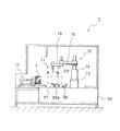
1は箱詰め装置であり、CD2、2、・・・は、図1に矢印Aで示すように、コンベア3上を搬送され、段積みユニット4によって積み上げられる。
【0015】
段積みユニット4は、図3に示すように、エレベータ5を有し、該エレベータ5はコンベア3によってCD2が運ばれて来る度に下降していき、これによってCD2が順次に積み重ねられていく。
【0016】
6は押し出し機構であり、ある高さまで積み上げられたCD群7を水平方向に押し出してスタック8に移送するために設けられている。
【0017】
9は仕切板挿入ユニットであり、押し出し機構6によってCD群7をスタック8に移送する際に当該CD群7と先に移送されたCD群7との間に仕切板10を挿入するものである。
【0018】
11は充填機構であり(図1、図2参照。)、スタック8が一杯になったときにCD群7、7・・・を水平方向に移動して段ボール箱内に収納するために設けられている。
【0019】
12は水平多関節型ロボットであり、箱詰め作業のうちの主要な作業を担当する。水平多関節型ロボット12は、図2に示すように、箱詰め装置1の基台13に固定された基軸部14と、該基軸部14に対して回動可能な状態で設けられた第1アーム15と、該第1アーム15に対して回動可能な状態で設けられた第2アーム16とからなっており、第2アーム16の先端部に設けられたハンド17が第1アーム15及び第2アーム16の回動に伴って水平面内に移動される(図1に1点鎖線で示す範囲18が水平多関節型ロボット12の作業エリアを示している。)。尚、ハンド17は鉛直軸の回りに回動されるとともに、第2アーム16に設けられた図示しない駆動手段によって上下方向に摺動されるように構成されており、後述するようにハンド17にはローラを付加した真空吸着ハンドが用いられている。
【0020】
19は段ボール供給ユニットであり(図1、図4参照。)、コンベア20とリフト21とから構成されている。折り畳まれた状態で鉛直方向に積み重ねられた段ボール群22は、図1に矢印Bで示すように、コンベア20によってその一部が水平多関節型ロボット12の作業エリア18に入る位置まで搬送され、それからリフト21により所定の供給位置まで持ち上げられる。
【0021】
水平多関節型ロボット12は最も高い位置にある段ボールをハンド17によって取り出した後、図1に2点鎖線の四角形Rで示す位置に移動してから段ボールを箱状に整形する。
【0022】
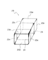
図5は整形後の段ボール箱23を示すものであり、開口24、24の縁にそれぞれ設けられた上フラップ23a、23a、下フラップ23b、23b、左右の側フラップ23c、23c、・・・はいづれも未だ折り曲げられていない状態となっている。
【0023】
25はフラップ開けユニットであり(図1参照。)、充填機構11によってCD群7、7、・・・を段ボール箱23内に挿入する際に段ボール箱23のフラップが邪魔にならないようにフラップを開いて段ボール箱23の一方の開口24を確保するために設けられている。
【0024】
26はフラップ折りユニットであり、26a、26aが段ボール箱23の側フラップ23c、23cをそれぞれ折り曲げ、26bが段ボール箱23の下フラップ23bを折り曲げるために設けられている。
【0025】
27は回転テーブル(図2参照。)であり、その上に段ボール箱23が載置される。回転テーブル27はその鉛直軸の回りに回転自在な状態とされており、図示しない駆動手段によって上下方向に移動されるようになっている。
【0026】
28は封緘ユニット(図1参照。)であり、CD群が収納された段ボール箱のフラップをテープや接着剤等を使って閉じるために設けられている。尚、封緘ユニット28は、回転テーブル27と水平多関節型ロボット12の基軸部14との間に位置して水平方向に延びるガイド部材28aに沿って摺動されるようになっている。
【0027】
29は水平多関節型ロボット12により段ボール箱を起こすのを補助するための補助ローラであり、フラップ折りユニット26bの近辺に設けられている。
【0028】
段ボール箱はその封緘された面が上下方向を向くように水平多関節型ロボット12のハンド17及び補助ローラ29によって起こされた後、コンベア30に載せられて、図1に矢印Cに示すように、搬送される。
【0029】
31はラベル貼付装置であり、コンベア30によって運ばれて来る段ボール箱の側面にラベルを貼り付けるために設けられている。
【0030】
段ボール箱はラベル貼付後に排出用コンベア32に移送され、図1に矢印Dで示すように、コンベア30の搬送方向とは直交する方向に搬送されて排出され、検査工程へと送られる。
【0031】
尚、コンベア20、30や排出用コンベア32の高さ、回転テーブル27の高さは略同じにされている。
【0032】
33は操作盤、34は制御盤であり、操作盤33は、図1及び図3に示すように、充填機構11の近辺に設けられ、また、制御盤34は、図2に示すように、装置側面の下端寄りのところに設けられている。
【0033】
35は水平多関節型ロボット12を制御するロボットコントローラであり、図3に示すように、装置の底部に配置されている。
【0034】
図6及び図7は箱詰め装置1の要部を示すものである。
【0035】
図6は回転テーブル27とフラップ折りユニット26を中心に示す平面図であり、回転テーブル27は作業台36の一部に組み込まれている。
【0036】
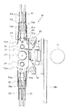
回転テーブル27は、図7の縦断面図に示すように、その回転軸27aがベアリングホルダー37内のベアリング38、38によって回転自在に支持されている。
【0037】
ベアリングホルダー37は支持板39に固定されており、該支持板39は2本のシャフト40、40の上端部に固定されている。シャフト40、40は、中空円筒状の支持部材41、41にそれぞれ挿通され、互いに一定の距離を保って上下方向に摺動自在な状態で支持されている。
【0038】
支持部材41、41はそれらの下端寄りの部分が取付板42に形成された挿通孔42a、42aにそれぞれ挿通されており、支持部材41、41のフランジ部41a、41aが取付板42の上面に固定されている。尚、取付板42は基台43に形成された孔43aを上方から覆うようにして基台43の上面に固定されている。
【0039】
シャフト40、40の下端部には平板44が固定されており、該平板44がフローティングジョイント45を介してアクチュエータ46の摺動軸46aに結合されている。尚、アクチュエータ46はその上端部が上記取付板42の下面に固定されていおり、その摺動軸46aが上下方向に移動される。よって、アクチュエータ46が平板44及びシャフト40、40を引き上げることによって、図7に2点鎖線で示すように、回転テーブル27が上昇することになる。
【0040】
47、47は真空吸着パッドであり、回転テーブル27を挟むようにして作業台36に取り付けられている。真空吸着パッド47、47は、それらの吸着面が上方を向いており、吸着面の高さが作業台36の上面の高さに略等しくされている。
【0041】
48は位置決め用のアクチュエータ(図7にのみ示す。)であり、図7に2点鎖線で示す段ボール箱23の一側面を摺動部48aで水平方向に押圧して、段ボール箱23の他方の側面を作業台36に立設されたストッパー49、49に当接させることによって段ボール箱23の位置決めを行うために設けられている。
【0042】
50、50はロータリーアクチュエータであり(図6参照。)、その爪部50a、50aが回転して段ボール箱23の下フラップ23bの端寄りの部分を押さえるために設けられている。
【0043】
フラップ折りユニット26a、26aは、図6に示すように、作業台36の長手方向の両脇に設けられており、シリンダ51、51の摺動杆51a、51aの先端に側フラップ23c、23cを折り曲げるための爪片51b、51bが取り付けられている。
【0044】
また、段ボール箱23の下フラップ23bを折り曲げるフラップ折りユニット26bは、ロータリーアクチュエータ50と50との間であって作業台36の近くに配置されている。
【0045】
52、52はフラップ折りユニット26a、26aの近くに配置された押さえユニットであり、段ボール箱の封緘時に封緘面とは反対側の面を押さえるものである。押さえユニット52、52は、そのシリンダ53、53の摺動杆53a、53aの先端に押さえ爪53b、53bが取り付けられている。
【0046】
図8及び図9のフローチャート図及び図10乃至図23の概略図は、箱詰め作業について説明するものである。
【0047】
図8に示すように箱詰め作業では、CD群7のスタック8への集積作業と段ボール箱23の準備作業とが並行して行われる。
【0048】
ステップS1乃至S5は、段ボール箱の準備作業の手順を示しており、ステップS1において、水平多関節型ロボット12は段ボール供給ユニット19によって用意される段ボールの一を取り出して搬送する。即ち、図10に示すように、水平多関節型ロボット12はそのハンド17によって折り畳まれた状態の段ボールを吸着してこれを引き上げてからアームを回動させて所定位置(図1に示す四角形R)まで移動する。
【0049】
そして、次ステップS2において、図11に示すように、段ボールを箱状に整形する。図12はその様子を概略的に示すものであり、ハンド17は吸着部17a、17a(図ではその一方だけを示す。)と、ローラ17bとを有している。折り畳まれた状態の段ボールは図に実線で示すように吸着部17a、17aによって吸着されるが、ローラ17bの支持部材が図示しない駆動手段によって回動支点17cに関して回動し得るようになっており、図に2点鎖線で示すように、ローラ17bによって段ボールの側面を押し下げると、側方から見てそれまで平行四辺形状に折り畳まれていた段ボールが長方形状に整形される。
【0050】
ステップS3では、位置決め用のアクチュエータ48によって段ボール箱を摺動させて位置決め行い、作業台36の真空吸着パッド47、47によって段ボール箱23を吸着して保持する。
【0051】
次ステップS4では、図13に示すように、フラップ開けユニット25によって段ボール箱の一方の開口24のフラップ23a、23b、23c、23cを開いてこの状態を保持する。
【0052】
ステップS5においては、フラップを開けた方とは反対側の側フラップ23c、23cが閉じられる。即ち、図14に示すように、ロータリーアクチュエータ50、50の爪部50a、50aが段ボール箱23の下フラップ23bを少し下げて押さえる。尚、この時水平多関節型ロボット12は、ハンド17の吸着部17aによって段ボール箱の上フラップ23aを吸着して該上フラップ23aを持ち上げている。このように下フラップ23bを少し下げ、上フラップ23aを少し上げるのは、側フラップ23c、23cを折り曲げる際に上下のフラップが邪魔にならないようにするためである。図15はフラップ折りユニット26a、26aによって側フラップ23c、23cが折り曲げられる様子を示しており、フラップ折りユニット26a、26aの爪片51b、51bが水平方向に移動することによって側フラップ23c、23cがそれぞれ折り曲げられる。こうしてCD群7を段ボール箱23に充填する前準備が完了する。
【0053】
他方、CD2、2、・・・の集積作業についてはステップS6乃至ステップS10に示すように、CD群7の水平送りと仕切板10の挿入とが複数回行われてスタック8にCD群7が一時的に集められる(図16参照。)。
【0054】
即ち、ステップS6ではコンベア3に載って運ばれて来るCD2がエレベータ5の下降に伴って段積みユニット4により積み上げられる。
【0055】
次ステップS7においてスタック8から空かどうかが問われ、空でない場合にはステップS8に進み、空の場合にはステップS9に飛ぶ。
【0056】
ステップS8において、CD群7をスタック8に移送するにあたって当該CD群7と先に移送されたCD群7との間に仕切板10が仕切板挿入ユニット9によって挿入される。
【0057】
次ステップS9では、段積みユニット4によって積み上げられたCDが所定の枚数に達した場合に、図16に示すように、CD群7が押し出し機構6によって水平方向に送られてスタック8に移される。
【0058】
ステップS10においてスタック8が一杯になったか否かが問われ、一杯であるならばステップ11に進み、そうでなければステップ8に戻ってステップS8、S9を繰り返す。
【0059】
ステップ11では、図17に示すように、スタック8に溜まったCD群7、7、・・・が充填機構11によって段ボール箱23内に収納される。
【0060】
そして、次ステップS12では、図18に示すように、ステップS4でフラップを開けた方とは反対側の上フラップ23aがハンド17のローラ17bによって折り曲げられ、また、下フラップ23bがフラップ折りユニット26bによって折り曲げられる。
【0061】
続くステップS13において、封緘ユニット28により段ボール箱23の一側面が閉じられる。例えば、図19に示すように、ガイド部材28aに沿う封緘ユニット28の水平移動によりクラフトテープ54が段ボール箱23に貼り付けられる。
【0062】
次ステップS14では、CD群が収納された段ボール箱が鉛直軸の回りに180°回転される。即ち、図20に示すように、アクチュエータ46によって回転テーブル27が上昇して、段ボール箱23を持ち上げる。そして、水平多関節型ロボット12のハンド17が下りて、その吸着部17a、17aにより段ボール箱23の上面を吸着し、上下方向に沿うハンド17の軸回りに段ボール箱を180°回転させる。尚、その際、フラップ開けユニット25によるフラップの開き動作や作業台36の真空吸着パッド47、47による段ボール箱の吸着が解除されていることは勿論である。段ボール箱23が回転されると、アクチュエータ46によって回転テーブル27が下降して元の位置に戻る。本例ではCD群7が収納された段ボール箱の重量が大きいため、ハンド17によって段ボール箱を持ち上げることは避け、回転テーブル27を補助的に用いることによって段ボール箱23を必要最小限のトルクでもって回転させている。
【0063】
ステップS15において、段ボール箱が図1の四角形Rに示す位置に来るように位置決めがなされた後は、段ボール箱の他方のフラップを閉じて封緘する作業が行われる。
【0064】
即ち、ステップS16において、段ボール箱23の側フラップ23c、23cを折り曲げた後、次ステップS17で上下のフラップ23a、23bを折り曲げ、それからステップ18でクラフトテープ54により段ボール箱23の残りの側面を封緘する(図21参照。)。そして、ステップ19で段ボール箱23を鉛直軸の回りに180°回転させる。
【0065】
ステップ20では、段ボール箱23をその封緘面が上下方向を向くように起き上がらせる。つまり、図22に示すように、補助ローラ29を上昇させるとともに、ハンド17のローラ17bによって段ボール箱23を矢印Eに示すように回転させ、段ボール箱23の封緘面の一方を補助ローラ29で受けて該補助ローラ29を下降させる。
【0066】
その後、ステップS21でコンベア30により段ボール箱23を搬送し、次ステップS22でラベル貼付装置31により段ボール箱23の一側面にラベルを貼り付けてコンベア32によって段ボール箱23を排出することで一連の箱詰め作業が終了する。
【0067】
以上の作業において段ボール箱の整形(S2)から側フラップ23cの折り曲げ(S5)に至る工程、CD群7の充填(S11)から段ボール箱の起こし(S20)に至るまでの工程は、図1の四角形Rで示す定位置又はその近辺で行われるので、段ボールを取り出して整形してから、CD群の段ボール箱への詰め込み、段ボール箱の封緘、段ボール箱の起こしまでの工程を限定された範囲で行うことができ、作業時間を短縮することができる。
【0068】
尚、上記の例では、段ボール箱の封緘にクラフトテープを使ったが、接着剤によるホットメルトを行っても良い。即ち、図23(a)に示すように、先ず、ホットメルトガン55によって段ボール箱23の側フラップ23c、23cに接着剤56、56、・・・を筋状に塗布した後、図23(b)に示すように上下のフラップを折り曲げて加熱圧着用部材57を上下フラップ23a、23bに押しつけて段ボール箱23を封緘する。従って、ホットメルトを行う場合にはステップS12、S13やS17、S18の代わりに図24に示すステップSA乃至SCの作業を行えば良い。つまり、ステップSAで側フラップ23c、23cに接着剤55を塗布してから次ステップSBで上下フラップ23a、23bを折り曲げて、ステップSCで接着剤56、56、・・・を加熱溶融して上下フラップ23a、23bを側フラップ23cに圧着し段ボール箱23を封緘する。尚、加熱圧着用部材57を段ボール箱23に押し付ける際には段ボール箱23が動かないように押さえユニット52、52によって段ボール箱23の反圧着側の面が押さえられる。
【0069】
また、上記の例では、段ボール箱の上下両面を封緘したが、検査の必要性から片面だけを封緘する場合には、ステップS14乃至S19が省略される。
【0070】
上記装置1にあっては、物品や段ボール箱のサイズを変更するにあたって水平多関節型ロボット12におけるハンドの交換等、比較的少数の箇所に変更や調整を加えるだけで対応することができるので従来の箱詰め専用機に比べて汎用性が高い。
【0071】
【発明の効果】
以上に記載したところから明らかなように、本発明物品の箱詰め装置によれば、吸着部や整形手段を有するロボットのハンド、折り蓋折り手段(上記実施例ではフラップ折りユニットに相当する。)、封緘手段(上記実施例では封緘ユニットに相当する。)などを整形後の折り箱の周囲に配置することによって、ロボットにより折り箱を整形してから上下の折り蓋を少し開いて押さえる工程、折り蓋を折り曲げる工程、折り箱を封緘する工程を略同じ場所で行うことができるので、工程間で折り箱を移送する必要がなくなり、装置の省スペース化を図ることができる。
【図面の簡単な説明】
【図1】本発明に係る箱詰め装置を概略的に示す平面図である。
【図2】本発明に係る箱詰め装置を概略的に示す側面図である。
【図3】本発明に係る箱詰め装置を概略的に示す側面図である。
【図4】本発明に係る箱詰め装置の段ボール供給ユニットを主に示す側面図である。
【図5】段ボール箱を示す斜視図である。
【図6】作業台とその周辺部を示す拡大平面図である。
【図7】作業台を示す拡大縦断面図である。
【図8】図9とともに箱詰め作業の流れを示すフローチャート図であり、本図は作業の前半部を示す。
【図9】箱詰め作業の流れを示すフローチャート図であり、作業の後半部を示す。
【図10】ロボットによる段ボールの取り出し工程を示す斜視図である。
【図11】ロボットによる段ボールの整形工程を示す斜視図である。
【図12】段ボール箱の整形について説明するための概略図である。
【図13】段ボール箱のフラップ開け工程を示す斜視図である。
【図14】段ボール箱の上下フラップの開き工程を示す斜視図である。
【図15】段ボール箱のフラップ折り工程を示す斜視図である。
【図16】CDの集積工程を示す斜視図である。
【図17】CD群の段ボール箱への収納工程を示す斜視図である。
【図18】段ボール箱のフラップ閉じ工程を示す斜視図である。
【図19】段ボール箱の封緘工程を示す斜視図である。
【図20】段ボール箱の回転を示す斜視図である。
【図21】段ボール箱の封緘工程を示す斜視図である。
【図22】段ボール箱の箱起こし工程を示す斜視図である。
【図23】ホットメルトによる段ボール箱の封緘工程を示すものであり、(a)は接着剤の塗布工程を示す斜視図、(b)は加熱圧着工程を示す斜視図である。
【図24】ホットメルトによる封緘工程の手順を示すフローチャート図である。
【図25】従来の箱詰め装置について説明するための斜視図である。
【符号の説明】
1 物品の箱詰め装置
11 充填機構(収納手段)
12 水平多関節型ロボット(ロボット)
17 ハンド
17a 吸着部
17b ローラ(整形手段)
19 段ボール供給ユニット(供給手段)
22 段ボール群
23 段ボール箱(折り箱)
23a、23b、23c フラップ(折り蓋)
23a 上側の折り蓋
26 フラップ折りユニット(折り蓋折り手段)
28 封緘ユニット(封緘手段)
55、57 封緘ユニット(封緘手段)[0001]
[Industrial application fields]
The present invention is intended to provide a novel article boxing device capable of reducing the size of the device.
[0002]
[Prior art]
There is known a boxing device that automates the operation of shaping a folded corrugated cardboard into a box and stuffing articles into the box. For example, the boxboard is performed through the steps shown in FIG.
[0003]
That is, when the articles b, b,... Are conveyed by the conveyor a, the articles b, b,... Are stacked as the elevator c descends, and are pushed out when the number reaches a predetermined value. The articles are accumulated in the stack e by being moved in the horizontal direction by the mechanism d. In addition, partition plates f, f,... Are inserted in a timely manner between the stacked article groups.
[0004]
When the stack e is full, the group of articles is moved in the horizontal direction by the filling mechanism g and packed into the cardboard box h. A sliding mechanism using a cylinder or the like is used for the pushing mechanism d and the filling mechanism g.
[0005]
The cardboard boxes h are stacked in an initially folded state, and are taken out and shaped by a dedicated supply mechanism.
[0006]
When the articles are packed into the shaped cardboard box h by the filling mechanism g, the cardboard box h is transferred to another place and the flaps i, i,... After that, sealing work is performed. For example, as shown in the figure, a tape attaching mechanism for moving the craft tape j to close the flap, or a hot melt mechanism for applying a heat-pressure bonding by applying an adhesive to the flap, although not shown, is used.
[0007]
The corrugated cardboard box h whose one end is sealed is further transferred, raised by being rotated at an angle of 90 ° around the axis along the conveying direction, and then sent to the labeling process and the inspection process.
[0008]
As described above, the boxing operation includes a series of operations such as loading of articles, transfer to a stack, removal and shaping of cardboard, packing of a group of articles into a cardboard box, sealing of cardboard boxes, and raising of cardboard boxes. This is done by an arranged mechanism.
[0009]
[Problems to be solved by the invention]
By the way, in the conventional boxing operation, the cardboard box storing the group of articles is transferred to another place and the flap is folded and sealed, so the total distance of the movement of the cardboard is increased. Therefore, there is a problem that the installation area of the apparatus becomes large.
[0010]
[Means for Solving the Problems]
Therefore, in order to solve the above-described problem, the boxing apparatus for articles according to the present invention transports at least a robot having a suction portion in a hand and folded boxes stacked in a vertical direction in a folded state, and supplies them around the robot. Supply means, shaping means for taking out the folded box and shaping it into a box, storage means for storing the article in the folded box, folding lid folding means for folding the folding lid of the folding box, and sealing means for sealing the folding lid In the boxing device for goods provided, the step of shaping the folding box with the hand of the robot and then opening and holding the upper and lower folding lids slightly up and down, the step of folding the folding lid, and the step of sealing the folding box are performed in substantially the same place the robot hand, flaps folding means, placed around the Oribako after shaping the sealing means, one stage from cardboard group by adsorption portion of the robot After moving into position removed Lumpur, which was as well as shaping into a box shape by the shaping means, for accommodating the articles in Oribako slightly open state an upper flaps by the suction unit is there.
[0011]
[Action]
According to the present invention, a robot hand having a suction part and a shaping means , a folding lid folding means, a sealing means, etc. are arranged around the shaped folding box, so that the robot can shape the folding box and then the upper and lower folding lids. Since the process of opening and holding a little, the process of folding the folding lid, and the process of sealing the folded box can be performed at substantially the same place, it is not necessary to transport the folded box in these processes, thereby reducing the installation area of the apparatus. it can.
[0012]
【Example】
Details of the boxing apparatus for articles of the present invention will be described below according to the illustrated embodiment.
[0013]
FIG. 1 to FIG. 4 show an outline of an article boxing apparatus according to the present invention, and the illustrated embodiment shows an example in which the present invention is applied to a compact disk (hereinafter referred to as “CD”) boxing apparatus. It is.
[0014]
1 is a boxing device, and
[0015]
As shown in FIG. 3, the
[0016]
[0017]
A partition
[0018]
[0019]
[0020]
[0021]
The horizontal articulated
[0022]
FIG. 5 shows the
[0023]
25 is a flap opening unit (refer to FIG. 1), and the flaps of the
[0024]
A
[0025]
[0026]
[0027]
[0028]
The cardboard box is raised by the
[0029]
[0030]
The cardboard box is transferred to the
[0031]
The heights of the
[0032]
33 is an operation panel, and 34 is a control panel. The
[0033]
[0034]
6 and 7 show the main part of the
[0035]
FIG. 6 is a plan view mainly showing the rotary table 27 and the
[0036]
As shown in the longitudinal sectional view of FIG. 7, the rotary table 27 has a
[0037]
The bearing
[0038]
The
[0039]
A
[0040]
[0041]
[0042]
[0043]
As shown in FIG. 6, the
[0044]
The
[0045]
52 and 52 are pressing units disposed near the
[0046]
The flowcharts of FIGS. 8 and 9 and the schematic diagrams of FIGS. 10 to 23 explain the boxing operation.
[0047]
As shown in FIG. 8, in the boxing operation, the stacking operation of the
[0048]
Steps S1 to S5 show the procedure for preparing the cardboard box. In step S1, the horizontal articulated
[0049]
Then, in the next step S2, the cardboard is shaped into a box shape as shown in FIG. FIG. 12 schematically shows such a state, and the
[0050]
In step S <b> 3, the cardboard box is slid and positioned by the
[0051]
In the next step S4, as shown in FIG. 13, the
[0052]
In step S5, the side flaps 23c and 23c on the opposite side to the side where the flap is opened are closed. That is, as shown in FIG. 14, the
[0053]
On the other hand, as shown in steps S6 to S10, the
[0054]
That is, in step S6, CD2 carried on the
[0055]
In next step S7, it is asked whether or not the
[0056]
In step S <b> 8, when the
[0057]
In the next step S9, when the number of CDs stacked by the stacking
[0058]
In step S10, it is asked whether or not the
[0059]
In
[0060]
Then, in the next step S12, as shown in FIG. 18, the
[0061]
In subsequent step S <b> 13, one side surface of the
[0062]
In the next step S14, the cardboard box containing the CD group is rotated 180 ° around the vertical axis. That is, as shown in FIG. 20, the rotary table 27 is raised by the
[0063]
In step S15, after the cardboard box is positioned so as to be in the position indicated by the rectangle R in FIG. 1, the other flap of the cardboard box is closed and sealed.
[0064]
That is, in step S16, the side flaps 23c and 23c of the
[0065]
In
[0066]
Thereafter, the
[0067]
The steps from the cardboard box shaping (S2) to the
[0068]
In the above example, kraft tape is used to seal the cardboard box, but hot melting with an adhesive may be performed. That is, as shown in FIG. 23A, first,
[0069]
In the above example, the upper and lower surfaces of the cardboard box are sealed. However, when only one surface is sealed due to the necessity of inspection, steps S14 to S19 are omitted.
[0070]
The
[0071]
【The invention's effect】
As is apparent from the above description, according to the boxing apparatus for articles of the present invention, a robot hand having a suction part and a shaping means , a folding lid folding means (corresponding to a flap folding unit in the above embodiment), and the like. By placing sealing means (corresponding to a sealing unit in the above embodiment) around the shaped folding box, the process of shaping the folding box by the robot and then opening and holding the upper and lower folding lids slightly, Since the step of folding and the step of sealing the folded box can be performed at substantially the same place, it is not necessary to transfer the folded box between the steps, and the space of the apparatus can be saved.
[Brief description of the drawings]
FIG. 1 is a plan view schematically showing a boxing device according to the present invention.
FIG. 2 is a side view schematically showing a boxing device according to the present invention.
FIG. 3 is a side view schematically showing a boxing device according to the present invention.
FIG. 4 is a side view mainly showing a cardboard supply unit of the boxing apparatus according to the present invention.
FIG. 5 is a perspective view showing a cardboard box.
FIG. 6 is an enlarged plan view showing a work table and its peripheral part.
FIG. 7 is an enlarged longitudinal sectional view showing a work table.
FIG. 8 is a flowchart showing the flow of the boxing operation together with FIG. 9, and this figure shows the first half of the operation.
FIG. 9 is a flowchart showing the flow of boxing work, and shows the latter half of the work.
FIG. 10 is a perspective view showing a cardboard taking-out process by the robot.
FIG. 11 is a perspective view showing a cardboard shaping process by a robot.
FIG. 12 is a schematic diagram for explaining cardboard box shaping.
FIG. 13 is a perspective view showing a flap opening process of a cardboard box.
FIG. 14 is a perspective view showing a process of opening the upper and lower flaps of the cardboard box.
FIG. 15 is a perspective view showing a flap folding process of a cardboard box.
FIG. 16 is a perspective view showing a CD integration process.
FIG. 17 is a perspective view showing a process of storing a CD group in a cardboard box.
FIG. 18 is a perspective view illustrating a flap closing process of a cardboard box.
FIG. 19 is a perspective view showing a cardboard box sealing step.
FIG. 20 is a perspective view showing rotation of a cardboard box.
FIG. 21 is a perspective view showing a cardboard box sealing step.
FIG. 22 is a perspective view showing a box raising process of a cardboard box.
FIG. 23 shows a sealing process of a cardboard box by hot melt, (a) is a perspective view showing an adhesive application process, and (b) is a perspective view showing a thermocompression bonding process.
FIG. 24 is a flowchart showing the procedure of a sealing process using hot melt.
FIG. 25 is a perspective view for explaining a conventional boxing device.
[Explanation of symbols]
DESCRIPTION OF
12 Horizontal articulated robot (robot)
17
17b Roller (shaping means)
19 Cardboard supply unit (supply means)
22
23a, 23b, 23c Flap (folding lid)
23a Upper folding lid
26 Flap folding unit (folding lid folding means)
28 Sealing unit (sealing means)
55, 57 Sealing unit (sealing means)
Claims (2)
ロボットのハンドにより折り箱を整形してから上下の折り蓋を上下に少し開いて押さえる工程、折り蓋を折り曲げる工程、折り箱を封緘する工程を略同じ場所で行うように、ロボットのハンド、折り蓋折り手段、封緘手段を整形後の折り箱の周囲に配置し、
上記ロボットの吸着部により段ボール群から1つの段ボールを取り出し所定の位置に移動させた後、上記整形手段により箱状に整形すると共に、上記吸着部により上側の折り蓋を少し開いた状態で物品を折り箱内に収納するようにしたことを特徴とする物品の箱詰め装置。A robot having at least a suction part in the hand, a supply unit that conveys folded boxes stacked in a vertical direction in a folded state and supplies the folded box to the periphery of the robot, a shaping unit that takes out the folded box and shapes it into a box shape, and an article In an article boxing device comprising storage means for storing the inside of the folding box, folding lid folding means for folding the folding lid of the folding box, and sealing means for sealing the folding lid,
The robot's hand, folding lid folding, so that the process of shaping the folding box with the robot's hand and then opening and holding the upper and lower folding lids slightly up and down, folding the folding lid, and sealing the folding box are performed in approximately the same place. Means, sealing means around the folded box after shaping,
After removing one cardboard from the cardboard group by the suction part of the robot and moving it to a predetermined position, it is shaped into a box shape by the shaping means , and the article is opened with the upper folding lid slightly opened by the suction part. An article boxing device characterized by being stored in a folded box.
Priority Applications (1)
| Application Number | Priority Date | Filing Date | Title |
|---|---|---|---|
| JP07549794A JP3674637B2 (en) | 1994-03-23 | 1994-03-23 | Equipment boxing equipment |
Applications Claiming Priority (1)
| Application Number | Priority Date | Filing Date | Title |
|---|---|---|---|
| JP07549794A JP3674637B2 (en) | 1994-03-23 | 1994-03-23 | Equipment boxing equipment |
Publications (2)
| Publication Number | Publication Date |
|---|---|
| JPH07257503A JPH07257503A (en) | 1995-10-09 |
| JP3674637B2 true JP3674637B2 (en) | 2005-07-20 |
Family
ID=13577972
Family Applications (1)
| Application Number | Title | Priority Date | Filing Date |
|---|---|---|---|
| JP07549794A Expired - Fee Related JP3674637B2 (en) | 1994-03-23 | 1994-03-23 | Equipment boxing equipment |
Country Status (1)
| Country | Link |
|---|---|
| JP (1) | JP3674637B2 (en) |
Cited By (1)
| Publication number | Priority date | Publication date | Assignee | Title |
|---|---|---|---|---|
| CN102514762A (en) * | 2011-11-03 | 2012-06-27 | 武汉人天包装技术有限公司 | Double-station box taking and pushing mechanism |
Families Citing this family (11)
| Publication number | Priority date | Publication date | Assignee | Title |
|---|---|---|---|---|
| US6766627B2 (en) * | 2001-05-14 | 2004-07-27 | Windings, Inc. | Machine for boxing wound coils of filamentary material |
| US8621831B2 (en) * | 2009-05-14 | 2014-01-07 | CapStone Technologies LLC | Robotic mail tray sleever apparatus |
| JP2014000823A (en) * | 2011-08-10 | 2014-01-09 | Yaskawa Electric Corp | Packing device |
| DE102012006278A1 (en) | 2012-03-29 | 2013-10-02 | Focke & Co. (Gmbh & Co. Kg) | Method and device for inserting packages into cartons |
| CN102963562A (en) * | 2012-12-05 | 2013-03-13 | 武汉人天包装技术有限公司 | Synchronous belt type bidirectional box taking and feeding device |
| CN103287626B (en) * | 2013-06-18 | 2014-09-24 | 李秀波 | Box sleeving machine |
| KR101984492B1 (en) * | 2017-07-03 | 2019-09-03 | 박준화 | Automatic Case Packer |
| ES2713331B2 (en) * | 2017-11-17 | 2019-10-25 | Telesforo Gonzalez Maqu Sl | METHOD FOR PRE-FEEDING IRONS IN AN IRON CHARGER OF A BOX FORMER MACHINE, PLANK PRE-FEEDER, AND INSTALLATION FOR THE FORMATION OF BOXES FROM IRONS |
| CN109264090A (en) * | 2018-09-10 | 2019-01-25 | 李孙 | System is opened in packaging bag and full-automatic bag seals packaging facilities |
| CN111907804A (en) * | 2020-08-27 | 2020-11-10 | 广州市富尔菱自动化系统有限公司 | Case unpacking machine |
| CN112644082B (en) * | 2020-12-29 | 2023-04-07 | 易程融创信息科技有限公司 | Apparatus for producing cartons |
-
1994
- 1994-03-23 JP JP07549794A patent/JP3674637B2/en not_active Expired - Fee Related
Cited By (2)
| Publication number | Priority date | Publication date | Assignee | Title |
|---|---|---|---|---|
| CN102514762A (en) * | 2011-11-03 | 2012-06-27 | 武汉人天包装技术有限公司 | Double-station box taking and pushing mechanism |
| CN102514762B (en) * | 2011-11-03 | 2013-07-03 | 武汉人天包装技术有限公司 | Double-station box taking and pushing mechanism |
Also Published As
| Publication number | Publication date |
|---|---|
| JPH07257503A (en) | 1995-10-09 |
Similar Documents
| Publication | Publication Date | Title |
|---|---|---|
| JP3674637B2 (en) | Equipment boxing equipment | |
| JP5351946B2 (en) | Packing equipment | |
| US5105600A (en) | Flexible apparatus and method for erecting and loading cases | |
| JP3659971B2 (en) | Apparatus and method for taking out and assembling paper box material | |
| CN108860855B (en) | Automatic packaging machine | |
| CN112678252B (en) | Packaging system | |
| CN112810295B (en) | Attached equipment of full-automatic sheet stock | |
| CN113665885B (en) | Full-automatic tray packaging machine | |
| CN113928614A (en) | Automatic packaging equipment | |
| JP2551295B2 (en) | Automatic cardboard box opening, article removal, folding method and device | |
| CN109178463A (en) | A kind of logistics packed in cases automation mould closer | |
| JP2005001304A (en) | Case making system | |
| CN214824545U (en) | Bagging equipment | |
| CN214294705U (en) | Automatic gluing and assembling equipment for paper box sticker and paper box | |
| CN115924175B (en) | Washing machine vanning device | |
| JPH07257502A (en) | Method and device for boxing article | |
| CN114537775B (en) | Robot gripper, boxing system and boxing method | |
| CN111688994A (en) | Automatic paper box folding device | |
| JPH07257520A (en) | Opening structure of folding cover of folding box | |
| CN217779114U (en) | Boxing system | |
| JP7016528B2 (en) | Boxing system | |
| CN112849537A (en) | Automatic packaging mechanism for desktop computer host | |
| JP2005119730A (en) | Robot type casing device | |
| JPH03111206A (en) | Method and device for continuous automatic packing of continuous business form paper for computer | |
| CN110561831A (en) | Automatic bottom box feeding machine |
Legal Events
| Date | Code | Title | Description |
|---|---|---|---|
| A131 | Notification of reasons for refusal |
Free format text: JAPANESE INTERMEDIATE CODE: A131 Effective date: 20040204 |
|
| A521 | Written amendment |
Free format text: JAPANESE INTERMEDIATE CODE: A523 Effective date: 20040326 |
|
| A131 | Notification of reasons for refusal |
Free format text: JAPANESE INTERMEDIATE CODE: A131 Effective date: 20040817 |
|
| A521 | Written amendment |
Free format text: JAPANESE INTERMEDIATE CODE: A523 Effective date: 20041018 |
|
| TRDD | Decision of grant or rejection written | ||
| A01 | Written decision to grant a patent or to grant a registration (utility model) |
Free format text: JAPANESE INTERMEDIATE CODE: A01 Effective date: 20050406 |
|
| A61 | First payment of annual fees (during grant procedure) |
Free format text: JAPANESE INTERMEDIATE CODE: A61 Effective date: 20050419 |
|
| LAPS | Cancellation because of no payment of annual fees |