JP3674062B2 - Treatment method of iron-containing metal wastewater - Google Patents
Treatment method of iron-containing metal wastewater Download PDFInfo
- Publication number
- JP3674062B2 JP3674062B2 JP26967694A JP26967694A JP3674062B2 JP 3674062 B2 JP3674062 B2 JP 3674062B2 JP 26967694 A JP26967694 A JP 26967694A JP 26967694 A JP26967694 A JP 26967694A JP 3674062 B2 JP3674062 B2 JP 3674062B2
- Authority
- JP
- Japan
- Prior art keywords
- sludge
- neutralization
- iron
- alkali
- containing metal
- Prior art date
- Legal status (The legal status is an assumption and is not a legal conclusion. Google has not performed a legal analysis and makes no representation as to the accuracy of the status listed.)
- Expired - Fee Related
Links
Images

Description
【0001】
【産業上の利用分野】
本発明は鉄含有金属排水の処理方法に係り、特に鉄含有金属排水を中和して不溶性水酸化物を生成させ、この水酸化物を含む汚泥と処理水とに分離し、分離した汚泥を中和工程に返送する鉄含有金属排水の処理方法において、高濃度汚泥を得るために必要な汚泥返送量の制御を容易に行って、低コストで効率的な処理を行う方法に関する。
【0002】
【従来の技術】
重金属含有排水の処理において、濃縮性に富み、脱水性に優れた高濃度重金属水酸化物汚泥を得る方法として、アルカリ汚泥法がある。この方法は、重金属含有排水にアルカリ剤を直接添加せずに、後工程のシックナーの排泥の一部と混合して添加する方法である(特公昭61−156号公報)。即ち、アルカリ汚泥法の原理は、汚泥にアルカリを添加し、汚泥に吸着されたアルカリで原水(重金属含有排水)を中和することにある。
【0003】
このようなアルカリ汚泥法において、汚泥分離工程から返送し、アルカリと混合して原水に添加する汚泥量については、下記式で算出される汚泥返送比Rが運転管理の指標として用いられ、この返送比Rは15〜40の範囲となるように、汚泥返送量が制御される(特開平5−57292号公報)、即ち、原水量、発生SS量、汚泥濃度を測定し、これらの測定値から、下記式より算出される返送比(R)が15〜40の範囲となるように、汚泥返送量が制御されている。
【0004】
【数1】

このような汚泥返送比Rに基く制御によれば、得られる汚泥濃度は従来の2〜3%から20〜30%と、大幅に向上する。
【0006】
【発明が解決しようとする課題】
上記従来の方法では、汚泥返送量の制御のために、原水流量、発生SS量、汚泥濃度及び汚泥返送量の各因子を測定するための計測機器と、汚泥返送比Rを算出するための演算システムが必要となり、設備が複雑かつ高価になるという問題がある。
【0007】
本発明者らは、上記従来の問題点を解決し、鉄含有金属排水を中和して不溶性水酸化物を生成させ、この水酸化物を含む汚泥と処理水とに分離し、分離した汚泥を中和工程に返送する方法において、高濃度汚泥を得るために必要な汚泥返送量の制御を、複雑な計測機器や演算システムを用いることなく容易に行って、低コストで効率的な処理を行う方法を提供することを目的とする。
【0008】
【課題を解決するための手段】
本発明の鉄含有金属排水の処理方法は、鉄含有金属排水を2段中和して、生成する鉄及び他の金属の水酸化物を含む汚泥と処理水とに分離する方法において、第1段の中和は、アルカリを添加することなく、pHが3.5〜5.0となるように前記の分離した汚泥を排水に添加することにより行い、第2段の中和は、前記の分離した汚泥を添加することなく、pHが8.0〜9.5となるようにアルカリを直接排水に添加することにより行うと共に、該第2段の中和を行う中和槽に空気を散気してFe 2+ の酸化を行うことを特徴とする。
【0009】
即ち、本発明者は、汚泥返送による重金属含有排水の中和処理について鋭意検討を重ねた結果、鉄(Fe3+)を含む排水であれば、前述の計測機器や演算システムを用いることなく、返送汚泥をpH計と連動させて循環させる簡単なシステムで最適汚泥返送量を制御可能であることを見出し、本発明を完成させた。
【0010】
【作用】
塩化第二鉄1000ppm(Fe3+として)溶液の水酸化ナトリウム(NaOH)による中和試験結果を下記表1に示す。表1より明らかなようにFe3+はpH4.0でほぼ完全に析出する。
【0011】
更にNaOHを添加すると、過剰になったNaOHは析出した水酸化物に吸着され、pH8〜9では吸着NaOH/析出水酸化物の比で1〜5%が吸着されていることが判明した。
【0012】
【表1】
従って、2段目の中和を8.0〜9.5で行って得られた汚泥を、第1段目の中和工程に原水の20〜100倍量返送すれば、この汚泥に吸着されているアルカリと原水中のFe3+とが反応して中和反応を終了させることができる。
【0014】
しかして、このときのpHはpH3.5〜5.0、好適にはpH4〜4.5で十分である。
【0015】
ところで、原水中に遊離酸が存在すると汚泥中のアルカリは遊離酸と反応するため、Fe3+の析出は不完全となる。このため、原水中の遊離の酸は予め中和しておく必要がある。
【0016】
通常、鉄を含む排水は酸洗ラインから排出される。酸洗ラインでは、一般には酸として塩酸,硫酸などの強酸が使用される。図2にH2 SO4 970ppmを含む硫酸希薄溶液をNaOHで中和した場合のpH曲線を示す。この図2より、pH3〜4で遊離酸の中和はほぼ終了しており、従って、遊離酸を含む原水であれば、pH3〜3.5で予備中和しておくことにより、金属イオンのみを中和処理できることが明らかである。
【0017】
【実施例】
以下、図面を参照して本発明の実施例について詳細に説明する。
【0018】
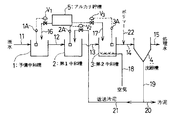
図1は本発明の鉄含有金属排水の処理方法の一実施例方法を示す系統図である。
【0019】
図1中、1は予備中和槽、2は第1中和槽、3は第2中和槽、4は沈殿槽、5はアルカリ貯槽であり、11〜22の各符号は配管を示す。配管16,21,17には各々バルブV1 ,V2 ,V3 が設けられており、各バルブは、それぞれ、各中和槽1,2,3に設けられたpH計1A,2A,3Aに連動するよう構成されている。
【0020】
本実施例の方法においては、原水(酸洗ラインから排出された遊離酸を含む、pH1.5〜2.0程度の鉄含有金属排水)は、まず、配管11より予備中和槽1に導入され、アルカリ貯槽5から配管16を経て添加されるアルカリにより予備中和される。この予備中和槽1においては、pH計1Aに連動するバルブV1 の開閉により、系内のpHがpH2.5〜3.5となるように予備中和することにより、原水中の遊離の酸を中和する。
【0021】
予備中和槽1の流出液は、次いで配管12より第1中和槽2に導入され、後段の沈殿槽4から配管19,21を経て返送される返送汚泥が添加されて、第1段目の中和が行われる。この第1中和槽2においては、pH計2Aに連動するバルブV2 の開閉により、系内のpHがpH3.5〜5.0、好ましくはpH4〜4.5となるような汚泥量が返送される。この第1中和槽2における第1段目の中和により、返送汚泥表面に吸着しているアルカリとの反応で鉄の水酸化物が汚泥表面に析出する。
【0022】
第1中和槽2の流出液は次いで配管13より第2中和槽3に導入され、アルカリ貯槽5から配管17を経て添加されるアルカリにより第2段目の中和が行われる。この第2中和槽3においては、pH計3Aに連動するバルブV3の開閉により、系内のpHがpH8.0〜9.5となるようにアルカリ添加量が調整され、汚泥表面へのアルカリの吸着が行われる。
【0023】
なお、この第2中和槽3には、配管18より空気が散気されており、これにより、Fe2+の酸化が行われる。
【0024】
第2中和槽3の流出液は、次いで配管14より沈殿槽4に導入されるが、その過程で、配管22よりポリマーが添加され、凝集が促進される。
【0025】
沈殿槽4で分離された上澄水は、配管15より処理水として系外へ排出される。一方、分離汚泥は配管19より抜き出され、必要量が返送汚泥として配管21より第1中和槽2に返送され、残部は配管20より系外へ排出され、脱水工程へ送給される。
【0026】
なお、原水中に第一鉄イオン(Fe2+)が多量に含まれる場合には、塩素系の酸化剤等を予備中和槽に添加して、予めFe2+をFe3+に酸化しておく。
【0027】
本発明において、原水に添加するアルカリとしては、水酸化ナトリウム、消石灰等のアルカリ剤が挙げられ、ポリマーとしてはポリアクリルアミド、その部分加水分解物等が挙げられる。このポリマーは、別途、凝集槽を設けて添加しても良い。
【0028】
このような方法により、複雑な測定機器や演算システムを必要とすることなく、一般的な汎用センサーであるpH計との連動により、汚泥返送量を適確に制御して、良好な処理を行える。
【0029】
なお、図示の方法は、本発明の一実施例方法であって、本発明はその要旨を超えない限り、何ら図示の方法に限定されるものではない。
【0030】
例えば、予備中和槽は必ずしも必要とされず、原水中の遊離酸の量が少ない場合には、省略することができる。
【0031】
また、本発明において、沈殿槽の代りに、固液分離手段として、膜分離手段を用いることも可能である。
【0032】
以下に具体的な実施例及び比較例を挙げて本発明をより詳細に説明する。
【0033】
実施例1
図1に示す本発明方法に従って下記水質の酸洗廃水の処理を行った。なお、装置の処理能力は5リットル/hrである。
【0034】
原水水質
pH:1.5〜2.5
T−Fe:100〜350ppm
Fe3+比率(T−Fe中のFe3+の割合):70〜90%
アルカリとしてはNaOHを用い、各中和槽のpHは、表2に示す範囲となるように、各々、アルカリ添加量又は汚泥返送量を制御した。
【0035】
得られた汚泥の濃度を表2に示す。
【0036】
比較例1
実施例1において、汚泥の返送を行わなかったこと以外は同様にして処理を行い、得られた汚泥の濃度を表2に示した。
【0037】
【表2】
表2より、本発明の方法によれば、pH計による汚泥返送量の連動制御のみで、高濃度汚泥を得ることができることが明らかである。
【0039】
【発明の効果】
以上詳述した通り、本発明の鉄含有金属排水の処理方法によれば、複雑な計測機器や演算システムを用いることなく、返送汚泥を一般的な汎用センサーであるpH計と連動させて循環させる簡単なシステムで、最適汚泥返送量を容易かつ適確に制御して、極めて清澄度の高い高水質の処理水及び高濃度で脱水性に優れた汚泥を安定かつ効率的に、低コストにて得ることが可能とされる。
【図面の簡単な説明】
【図1】本発明の鉄含有金属排水の処理方法の一実施例方法を示す系統図である。
【図2】硫酸希薄溶液をNaOHで中和した場合のpH曲線を示すグラフである。
【符号の説明】
1 予備中和槽
1A,2A,3A pH計
2 第1中和槽
3 第2中和槽
4 沈殿槽
5 アルカリ貯槽[0001]
[Industrial application fields]
The present invention relates to a method for treating iron-containing metal wastewater, in particular, neutralizing iron-containing metal wastewater to produce insoluble hydroxide, separating the sludge containing this hydroxide and treated water, and separating the separated sludge. The present invention relates to a method for performing efficient treatment at low cost by easily controlling the amount of sludge returned to obtain high-concentration sludge in a method for treating iron-containing metal wastewater returned to a neutralization step.
[0002]
[Prior art]
In the treatment of heavy metal-containing wastewater, there is an alkali sludge method as a method for obtaining high-concentration heavy metal hydroxide sludge that is rich in concentration and excellent in dewaterability. This method is a method in which an alkali agent is not added directly to heavy metal-containing wastewater, but is mixed with a part of wastewater from a thickener in the subsequent step (Japanese Patent Publication No. 61-156). That is, the principle of the alkaline sludge method is to add alkali to the sludge and neutralize raw water (heavy metal containing wastewater) with the alkali adsorbed on the sludge.
[0003]
In such an alkali sludge method, the sludge return ratio R calculated by the following formula is used as an index for operation management for the amount of sludge that is returned from the sludge separation step and mixed with the alkali and added to the raw water. The amount of sludge returned is controlled so that the ratio R is in the range of 15 to 40 (Japanese Patent Laid-Open No. 5-57292). That is, the raw water amount, the generated SS amount, and the sludge concentration are measured, and these measured values are used. The sludge return amount is controlled so that the return ratio (R) calculated from the following equation is in the range of 15-40.
[0004]
[Expression 1]
According to such control based on the sludge return ratio R, the obtained sludge concentration is greatly improved from 2 to 3% to 20 to 30%.
[0006]
[Problems to be solved by the invention]
In the above conventional method, in order to control the sludge return amount, a measuring device for measuring each factor of raw water flow rate, generated SS amount, sludge concentration and sludge return amount, and calculation for calculating the sludge return ratio R There is a problem that a system is required and the facilities are complicated and expensive.
[0007]
The present inventors have solved the above conventional problems, neutralized iron-containing metal wastewater to produce insoluble hydroxide, separated into sludge containing this hydroxide and treated water, and separated sludge In the method of returning the wastewater to the neutralization process, it is possible to easily control the amount of returned sludge required to obtain high-concentration sludge without using complicated measuring instruments and computing systems, and to achieve efficient processing at a low cost. It aims to provide a way to do.
[0008]
[Means for Solving the Problems]
The method for treating iron-containing metal wastewater according to the present invention is a method in which the iron-containing metal wastewater is neutralized in two stages and separated into sludge containing treated iron and other metal hydroxides and treated water. The neutralization of the stage is performed by adding the separated sludge to the waste water so that the pH becomes 3.5 to 5.0 without adding alkali, and the neutralization of the second stage is performed as described above. Without adding the separated sludge, the alkali is directly added to the waste water so that the pH is 8.0 to 9.5, and air is scattered in the neutralization tank for neutralizing the second stage. It is characterized by performing Fe 2+ oxidation .
[0009]
That is, the present inventor, as a result of intensive studies on the neutralization treatment of heavy metal-containing wastewater by returning sludge, as long as wastewater containing iron (Fe 3+ ), without using the above-described measuring instrument and arithmetic system, The present inventors have found that the optimum sludge return amount can be controlled with a simple system that circulates the return sludge in conjunction with the pH meter, and has completed the present invention.
[0010]
[Action]
Table 1 below shows the results of a neutralization test with sodium hydroxide (NaOH) of a 1000 ppm ferric chloride (as Fe 3+ ) solution. As is apparent from Table 1, Fe 3+ precipitates almost completely at pH 4.0.
[0011]
When NaOH was further added, excess NaOH was adsorbed on the precipitated hydroxide, and it was found that 1 to 5% was adsorbed at a ratio of adsorbed NaOH / precipitated hydroxide at pH 8-9.
[0012]
[Table 1]
Therefore, if the sludge obtained by neutralizing the second stage at 8.0 to 9.5 is returned 20 to 100 times the amount of raw water to the first stage neutralization process, it is adsorbed by this sludge. The neutralization reaction can be completed by the reaction between the alkali and the Fe 3+ in the raw water.
[0014]
Therefore, pH 3.5-5.0, preferably pH 4-4.5 is sufficient at this time.
[0015]
By the way, if free acid is present in the raw water, the alkali in the sludge reacts with the free acid, so that the deposition of Fe 3+ is incomplete. For this reason, it is necessary to neutralize the free acid in raw water beforehand.
[0016]
Usually, wastewater containing iron is discharged from the pickling line. In the pickling line, a strong acid such as hydrochloric acid or sulfuric acid is generally used as the acid. FIG. 2 shows a pH curve when a dilute sulfuric acid solution containing 970 ppm of H 2 SO 4 is neutralized with NaOH. From FIG. 2, neutralization of free acid is almost completed at pH 3 to 4. Therefore, in the case of raw water containing free acid, by pre-neutralizing at pH 3 to 3.5, only metal ions are obtained. It is clear that can be neutralized.
[0017]
【Example】
Hereinafter, embodiments of the present invention will be described in detail with reference to the drawings.
[0018]
FIG. 1 is a system diagram showing an embodiment of a method for treating iron-containing metal wastewater according to the present invention.
[0019]
In FIG. 1, 1 is a pre-neutralization tank, 2 is a 1st neutralization tank, 3 is a 2nd neutralization tank, 4 is a precipitation tank, 5 is an alkali storage tank, and each code | symbol of 11-22 shows piping. The
[0020]
In the method of this embodiment, raw water (iron-containing metal wastewater having a pH of about 1.5 to 2.0 including free acid discharged from the pickling line) is first introduced into the preliminary neutralization tank 1 from the pipe 11. Then, it is pre-neutralized by the alkali added from the alkali storage tank 5 through the
[0021]
The effluent from the preliminary neutralization tank 1 is then introduced into the
[0022]
The effluent from the
[0023]
Note that air is diffused from the
[0024]
The effluent from the second neutralization tank 3 is then introduced into the
[0025]
The supernatant water separated in the
[0026]
If the raw water contains a large amount of ferrous ion (Fe 2+ ), a chlorine-based oxidant or the like is added to the pre-neutralization tank to previously oxidize Fe 2+ to Fe 3+. Keep it.
[0027]
In the present invention, examples of the alkali added to the raw water include alkali agents such as sodium hydroxide and slaked lime, and examples of the polymer include polyacrylamide and a partially hydrolyzed product thereof. This polymer may be added separately by providing a coagulation tank.
[0028]
By such a method, the sludge return amount can be appropriately controlled by the linkage with a pH meter which is a general general-purpose sensor without requiring a complicated measuring instrument or a calculation system, and a good treatment can be performed. .
[0029]
The illustrated method is an example method of the present invention, and the present invention is not limited to the illustrated method as long as the gist of the present invention is not exceeded.
[0030]
For example, the preliminary neutralization tank is not necessarily required, and can be omitted when the amount of free acid in the raw water is small .
[0031]
In the present invention, it is also possible to use a membrane separation means as the solid-liquid separation means instead of the precipitation tank.
[0032]
Hereinafter, the present invention will be described in more detail with reference to specific examples and comparative examples.
[0033]
Example 1
In accordance with the method of the present invention shown in FIG. The processing capacity of the apparatus is 5 liters / hr.
[0034]
Raw water quality pH: 1.5-2.5
T-Fe: 100 to 350 ppm
Fe 3+ ratio (the ratio of Fe 3+ in the T-Fe): 70~90%
NaOH was used as the alkali, and the alkali addition amount or sludge return amount was controlled so that the pH of each neutralization tank was in the range shown in Table 2.
[0035]
Table 2 shows the concentration of the obtained sludge.
[0036]
Comparative Example 1
In Example 1, the treatment was performed in the same manner except that the sludge was not returned, and the resulting sludge concentration is shown in Table 2.
[0037]
[Table 2]
From Table 2, it is clear that according to the method of the present invention, high-concentration sludge can be obtained only by interlocking control of the sludge return amount with a pH meter.
[0039]
【The invention's effect】
As described in detail above, according to the iron-containing metal wastewater treatment method of the present invention, return sludge is circulated in conjunction with a pH meter, which is a general general-purpose sensor, without using a complicated measuring instrument or calculation system. Easy and accurate control of the optimal sludge return rate with a simple system, enabling high-quality treated water with extremely high clarity and sludge with high concentration and excellent dewaterability to be stably and efficiently at low cost. It is possible to obtain.
[Brief description of the drawings]
FIG. 1 is a system diagram showing an embodiment method of a method for treating iron-containing metal wastewater according to the present invention.
FIG. 2 is a graph showing a pH curve when a dilute sulfuric acid solution is neutralized with NaOH.
[Explanation of symbols]
1
Claims (1)
第1段の中和は、アルカリを添加することなく、pHが3.5〜5.0となるように前記の分離した汚泥を排水に添加することにより行い、
第2段の中和は、前記の分離した汚泥を添加することなく、pHが8.0〜9.5となるようにアルカリを直接排水に添加することにより行うと共に、該第2段の中和を行う中和槽に空気を散気してFe 2+ の酸化を行う
ことを特徴とする鉄含有金属排水の処理方法。In a method of neutralizing iron-containing metal wastewater in two stages and separating it into sludge containing treated iron and other metal hydroxides and treated water,
The neutralization of the first stage is performed by adding the separated sludge to the waste water so that the pH becomes 3.5 to 5.0 without adding alkali,
The neutralization of the second stage is carried out by adding alkali directly to the waste water so that the pH becomes 8.0 to 9.5 without adding the separated sludge . An iron-containing metal wastewater treatment method, wherein air is diffused into a neutralization tank for summing to oxidize Fe < 2+ > .
Priority Applications (1)
| Application Number | Priority Date | Filing Date | Title |
|---|---|---|---|
| JP26967694A JP3674062B2 (en) | 1994-11-02 | 1994-11-02 | Treatment method of iron-containing metal wastewater |
Applications Claiming Priority (1)
| Application Number | Priority Date | Filing Date | Title |
|---|---|---|---|
| JP26967694A JP3674062B2 (en) | 1994-11-02 | 1994-11-02 | Treatment method of iron-containing metal wastewater |
Publications (2)
| Publication Number | Publication Date |
|---|---|
| JPH08132068A JPH08132068A (en) | 1996-05-28 |
| JP3674062B2 true JP3674062B2 (en) | 2005-07-20 |
Family
ID=17475649
Family Applications (1)
| Application Number | Title | Priority Date | Filing Date |
|---|---|---|---|
| JP26967694A Expired - Fee Related JP3674062B2 (en) | 1994-11-02 | 1994-11-02 | Treatment method of iron-containing metal wastewater |
Country Status (1)
| Country | Link |
|---|---|
| JP (1) | JP3674062B2 (en) |
Families Citing this family (1)
| Publication number | Priority date | Publication date | Assignee | Title |
|---|---|---|---|---|
| JP4626268B2 (en) * | 2004-10-28 | 2011-02-02 | 栗田工業株式会社 | Method for treating copper-containing liquid |
-
1994
- 1994-11-02 JP JP26967694A patent/JP3674062B2/en not_active Expired - Fee Related
Also Published As
| Publication number | Publication date |
|---|---|
| JPH08132068A (en) | 1996-05-28 |
Similar Documents
| Publication | Publication Date | Title |
|---|---|---|
| CN213060470U (en) | Sulfuric acid process titanium dioxide effluent treatment plant | |
| JP3674062B2 (en) | Treatment method of iron-containing metal wastewater | |
| JP2004249258A (en) | Wastewater treatment method | |
| CN108503103A (en) | The method for handling waste water | |
| JPH05337474A (en) | Treatment of waste water containing heavy metal | |
| JP3642516B2 (en) | Method and apparatus for removing COD components in water | |
| JP2847864B2 (en) | Chromium-containing wastewater treatment method | |
| KR101420656B1 (en) | Method for treatment of wastewater containing cyanide | |
| JP2007260556A (en) | Phosphoric acid-containing wastewater treatment method and apparatus | |
| JP4103230B2 (en) | Treatment method for wastewater containing hexavalent chromium | |
| JP2721740B2 (en) | Chemical cleaning waste liquid treatment method | |
| JPS61161191A (en) | Treatment of heavy metal ion-containing solution | |
| JP2001293486A (en) | Method for treating hexavalent chromium-containing waste water | |
| JP3632226B2 (en) | Method for treating metal-containing wastewater | |
| JPS6178491A (en) | Treatment of pickling rinse waste liquid | |
| CN114620858B (en) | Method for treating nickel-containing waste liquid | |
| CN218931872U (en) | Cyanide-containing electroplating wastewater decyanation treatment system | |
| JP3240940B2 (en) | Treatment method for selenium-containing water | |
| Owens | Iron and Manganese Removal by Split‐Flow Treatment | |
| JP3658775B2 (en) | Treatment method for wastewater containing metal ions | |
| JPH0128629B2 (en) | ||
| JP4305938B2 (en) | Treatment method for wastewater containing hexavalent chromium | |
| JP2003104728A (en) | Method for treating iron-containing sulfuric acid solution | |
| JP2023167782A (en) | Method and apparatus for treating wastewater containing organic chelating agent and heavy metals | |
| CN111072176A (en) | Treatment method of leaching solution containing arsenic acid |
Legal Events
| Date | Code | Title | Description |
|---|---|---|---|
| A131 | Notification of reasons for refusal |
Free format text: JAPANESE INTERMEDIATE CODE: A131 Effective date: 20040601 |
|
| A521 | Written amendment |
Free format text: JAPANESE INTERMEDIATE CODE: A523 Effective date: 20040727 |
|
| TRDD | Decision of grant or rejection written | ||
| A01 | Written decision to grant a patent or to grant a registration (utility model) |
Free format text: JAPANESE INTERMEDIATE CODE: A01 Effective date: 20050405 |
|
| A61 | First payment of annual fees (during grant procedure) |
Free format text: JAPANESE INTERMEDIATE CODE: A61 Effective date: 20050418 |
|
| R150 | Certificate of patent or registration of utility model |
Free format text: JAPANESE INTERMEDIATE CODE: R150 |
|
| FPAY | Renewal fee payment (event date is renewal date of database) |
Free format text: PAYMENT UNTIL: 20090513 Year of fee payment: 4 |
|
| FPAY | Renewal fee payment (event date is renewal date of database) |
Free format text: PAYMENT UNTIL: 20090513 Year of fee payment: 4 |
|
| FPAY | Renewal fee payment (event date is renewal date of database) |
Free format text: PAYMENT UNTIL: 20100513 Year of fee payment: 5 |
|
| FPAY | Renewal fee payment (event date is renewal date of database) |
Free format text: PAYMENT UNTIL: 20110513 Year of fee payment: 6 |
|
| FPAY | Renewal fee payment (event date is renewal date of database) |
Free format text: PAYMENT UNTIL: 20120513 Year of fee payment: 7 |
|
| FPAY | Renewal fee payment (event date is renewal date of database) |
Free format text: PAYMENT UNTIL: 20130513 Year of fee payment: 8 |
|
| FPAY | Renewal fee payment (event date is renewal date of database) |
Free format text: PAYMENT UNTIL: 20140513 Year of fee payment: 9 |
|
| LAPS | Cancellation because of no payment of annual fees |