JP3560694B2 - Lens inspection system and method - Google Patents
Lens inspection system and method Download PDFInfo
- Publication number
- JP3560694B2 JP3560694B2 JP16813195A JP16813195A JP3560694B2 JP 3560694 B2 JP3560694 B2 JP 3560694B2 JP 16813195 A JP16813195 A JP 16813195A JP 16813195 A JP16813195 A JP 16813195A JP 3560694 B2 JP3560694 B2 JP 3560694B2
- Authority
- JP
- Japan
- Prior art keywords
- lens
- light beam
- image
- subsystem
- pixel
- Prior art date
- Legal status (The legal status is an assumption and is not a legal conclusion. Google has not performed a legal analysis and makes no representation as to the accuracy of the status listed.)
- Expired - Lifetime
Links
Images


Classifications
-
- G—PHYSICS
- G01—MEASURING; TESTING
- G01M—TESTING STATIC OR DYNAMIC BALANCE OF MACHINES OR STRUCTURES; TESTING OF STRUCTURES OR APPARATUS, NOT OTHERWISE PROVIDED FOR
- G01M11/00—Testing of optical apparatus; Testing structures by optical methods not otherwise provided for
- G01M11/02—Testing optical properties
- G01M11/0242—Testing optical properties by measuring geometrical properties or aberrations
- G01M11/0257—Testing optical properties by measuring geometrical properties or aberrations by analyzing the image formed by the object to be tested
- G01M11/0264—Testing optical properties by measuring geometrical properties or aberrations by analyzing the image formed by the object to be tested by using targets or reference patterns
-
- B—PERFORMING OPERATIONS; TRANSPORTING
- B29—WORKING OF PLASTICS; WORKING OF SUBSTANCES IN A PLASTIC STATE IN GENERAL
- B29D—PRODUCING PARTICULAR ARTICLES FROM PLASTICS OR FROM SUBSTANCES IN A PLASTIC STATE
- B29D11/00—Producing optical elements, e.g. lenses or prisms
- B29D11/00951—Measuring, controlling or regulating
- B29D11/0098—Inspecting lenses
-
- G—PHYSICS
- G01—MEASURING; TESTING
- G01M—TESTING STATIC OR DYNAMIC BALANCE OF MACHINES OR STRUCTURES; TESTING OF STRUCTURES OR APPARATUS, NOT OTHERWISE PROVIDED FOR
- G01M11/00—Testing of optical apparatus; Testing structures by optical methods not otherwise provided for
- G01M11/02—Testing optical properties
- G01M11/0242—Testing optical properties by measuring geometrical properties or aberrations
- G01M11/0278—Detecting defects of the object to be tested, e.g. scratches or dust
Abstract
Description
【0001】
【産業上の利用分野】
本発明は,一般的には眼科用レンズの検査システム,特定的にはコンタクトレンズを高速かつ自動的に検査するためのシステムに関する。
【0002】
【従来の技術】
最近,眼科用レンズ,特にコンタクトレンズを製作するための幾つかの自動化システムが開発されているが,このようなシステムの一例が米国特許第5,080,839号で公開されている。このシステムでは極めて高度な自動化が実現されており,例えばレンズをモールドし,これをモールド型から取り外して更に処理したあと,直接人手を煩わさずに包装することができる。
【0003】
しかもこの自動化システムでは,コンタクトレンズ等が極めて精密かつ正確に製作される。しかし個々のレンズについては稀に狂いが生じることもあり得るので,コンタクトレンズは,これを顧客に販売する前にこれが顧客の使用に耐えうるか否かが検査される。
【0004】
眼科用レンズを自動的に検査することも可能であり,信頼性が極めて高くかつ正確な自動化レンズ検査システムが公知である。このような自動化システムのあるものは,専らレンズの周辺,すなわち外郭部分を検査するシステムであるが,このようなシステムは,レンズの中心部分をより良く検査する手順を設けることによって更に改良することが可能ではないかと信じられている。
【0005】
【発明が解決しようとする課題】
本発明の目的は,眼科用レンズ検査のためのシステムを改良することである。
【0006】
本発明の他の目的は,レンズ中心部の欠陥を拡大したレンズの映像を生成させるための照明システム付の自動化レンズ検査システムを提供することである。
【0007】
本発明のもう一つの目的は,コンタクトレンズの映像を,そのレンズ周辺部を目で識別可能にすることである。
【0008】
本発明の更に異なる目的は,コンタクトレンズの中心部の極めて小さな狂いを検査するための自動化システムを提供することである。
【0009】
【課題を解決するための手段】
上記の各目的は,眼科用レンズ検査のためのシステムと方法とによって達成されるが,このシステムには,レンズを検査位置に移動させるための輸送サブシステム,レンズを透過するように光ビームを指向させる照明サブシステム,レンズを透過する光ビームに対応した1群の信号を生成させるためのイメージングサブシステムおよびこれらの信号を処理するためのサブシステムが包含される。また照明サブシステムには,一般に,光ビームの横断面での光の強さが不均一な光ビームを生成させるためのディフューザーが含まれる。
【0010】
【実施例】
図1にレンズ検査システム10が描かれているが,一般的にこのシステム10は,輸送サブシステム12,照明サブシステム14,イメージングサブシステム16およびプロセッシングサブシステム20で構成される。またこの図1には,排除(リジェクト)機構22,排除コントローラー24,およびそれぞれが1群のレンズパッケージを保持する複数個のパレット30も示されている。
【0011】
図1および図2において,輸送サブシステム12はコンベヤーベルト32付とするのが好ましく,また照明サブシステム14にはケース34,光源36,リフレクター40,レンズ42と44が含まれる。すなわちこの好ましいシステム10によれば,イメージングサブシステム16にはカメラ46が含まれるが,このカメラは,ケース50,ピクセルアレー52,シャッター54および複合レンズ56で構成される。プロセッシングサブシステム20には,イメージ処理手段60,オペレーターとのインターフェース手段62および監視用コンピューター64が含まれるが,より詳細に述べれば,プロセッサー手段には複数のプロセッサーとメモリーボード60a,60bおよび60cが,またインターフェース手段にはモニター66とホストコンピューター70とがそれぞれ含まれる。
【0012】
一般に輸送サブシステム12によって,多数の眼科用レンズが予め定められた通路沿いにレンズ検査システム(図1の72)の中に運ばれる。また照明サブシステム14によって光ビームが生成され,このビームが,レンズ検査位置を通過して移動するレンズに指向されてこれを透過する。そしてサブシステム16が,検査対象の各レンズを透過する光ビームもしくはその一部に対応して1群の信号を生成し,これらの信号をプロセッシングサブシステム20に伝送する。サブシステム20はサブシステム16からこれらの信号を受け取り,所定のプログラムに従ってこれらの信号を処理する。検査されるそれぞれのレンズに対してサブシステム20は,当該レンズの少なくとも一つの状態を示す信号を生成するが,以下に詳細を説明するサブシステム20の実施例によれば,このサブシステム20は,検査対象のそれぞれのレンズが顧客の使用に適しているか否かを示す信号を生成する。
【0013】
このシステム10は,タイプやサイズが各種各様な眼科用レンズの検査に使用することができるが,特にコンタクトレンズの検査に適しており,このシステム10で検査可能なコンタクトレンズ74の例を図3と図4に示す。レンズ74は,一般に前面76と背面80とを備えた中空な半球状で,光学的中心ゾーン74aと周辺ゾーン74bとを形成する。このレンズの厚みは実質的に均一であるが,レンズ外縁に接した環状部74cでは厚さが次第に薄くなる。
【0014】
このシステム10の好ましい運転状態においては,各レンズが個別のパッケージすなわちキャリアの中に配置され,これらのキャリアがパレット30の中に保持されるが,このパレット30がコンベア32によって運搬されて検査位置72を通過する。そしてシステム20によれば,さまざまなタイプのレンズキャリアとレンズパレットとを使用することができるが,レンズ74を保持するのに使用可能なキャリア82を図5と図6に,また1群のパッケージ82を保持するのに使用可能なパレット30を図7に示す。
【0015】
キャリア82は,実質的に平坦な第一面84を有し,この第一面84内に窪み86が形成されている。そして各キャリア82それぞれの窪み86の中にレンズ74が配置されるが,これらのレンズ74はキャリアの窪み86の中の脱イオン水等の液体の中に完全に浸すのが好ましい。また窪み86の曲率半径rを,この中に置かれる眼科用レンズ74のそれよりも大とすることにより,レンズ74を, 窪み86の中に置いたとき,窪み86を形成するキャリア82表面の形状に従ってレンズ74の中心が窪み86の頂部にフィットするようにするのが好ましい。
【0016】
窪み86の中には,その中心付近に間隔を隔てて配置された複数の筋状マーク(リブマーク)90が設けられているが,これらのマーク90は,窪み86から脱イオン水を取り去ったとき,レンズ74を窪み86の中に保持するのに役立つ。しかしレンズ74と窪み86それぞれの中心を合わせたとき,レンズ74が筋状マーク90に接触せずに窪み86頂部の中心にのみ点状にタッチするのが好ましい。
窪み86の中には,その中心付近に間隔を隔てて配置された複数の筋状マーク(リブマーク)90が設けられているが,これらのマーク90は,窪み86から脱イオン水を取り去ったとき,レンズ74を窪み86の中に保持するのに役立つ。しかしレンズ74と窪み86それぞれの中心を合わせたとき,レンズ74が筋状マークに接触せずに窪み86頂部の中心にのみ点状にタッチするのが好ましい。図に示されているキャリア82の実施例によれば、筋状の各マーク90は、長さ0.5mm,幅が0.02mmで、各マーク90は窪み86の中心から3.0mm,また同一直線上の仲間の終端から6.0mm,それぞれ離れて配置されている。
【0017】
このシステム10は,レンズをレンズキャリア82の中に置くための特定の方法や装置とは無関係に使用可能なので,レンズ74を自動方式で製作,検査,再処理したあと,ロボットないし自動式レンズハンドリング装置(図には描かれていない)でこれをキャリア82の中に装填する大規模なシステムでの使用に好適である。
【0018】
図7に示されているパレット30の実施例によれば,このパレット30が多数のパッケージすなわちキャリア82を2列に保持するように設計されているが,これにはキャリア82を受け入れるための窪み,すなわち受容部30aを設けとよい。このようによれば,システム10に2台のカメラ46を設け,パレット30内の各列のパッケージ82それぞれを検査することができるようになる。またこのシステムには検査用カメラを追加装備可能で,例えばレンズ74の周辺エリア検査専用のカメラを追加するとよい。
【0019】
図1では,輸送サブシステム12のコンベアベルト32が1対もしくはそれ以上の滑車(図には描かれていない)の上に装着されており,ベルト32がこの滑車に支持されながらエンドレスに回動する。これの駆動手段は,レンズ74が連続的もしくは実質的に連続してスムーズにシステム10を通過するように運転させるのが好ましい。またこれの代案として,レンズ74を断続的すなわちステップ・バイ・ステップ方式でシステム10を通過させてもよく,特にイメージングサブシステム16の下では各レンズを短時間停止させてもよい。
【0020】
また,より特定的には,このシステム10は,パレット30の輸送に呼応してレンズグループを順繰りに検査するように設計するのが好ましい。このコンベアシステムは,リニアスライドに取り付けたアームによってパレット30を推進させる,いわゆるウォーキングビーム機構を利用したものである。このスライドを伸長させることによってパレット30を前進させるが,このスライドの伸長ストロークが完了するとそのアームが再び引き込まれ,スライドが初期位置に戻って次のパレットの移動が開始されるが,このパレット移動の全行程は,始動/加速段階と定速段階および減速/停止段階の3段階で構成される。そして定速移動期間中にレンズがカメラ46の下に位置して映写が実行される。この全サイクルは約12秒程度で,約12秒ごとに16個のレンズを処理するのが好ましい。すなわち好ましくは,パレット移動に伴って一つのパレットサイクルが開始され,パレットはカメラ46に到達する前に定速に達し,全レンズの映写が完了するまで定速に持続される。
【0021】
このシステム10には,これに適した排除機構22を設けるとよいが,この機構22はコントローラー24でコントロールするのが好ましく,特にコントローラー24が,当該レンズが不合格である旨の信号をサブシステム20から受け取った場合,機構22がコントローラー24によって活かされ,当該レンズを保持しているパッケージが,排除機構を通過中のパッケージの流れから取り除かれる。システム10の好ましい運転状態においては,レンズ74がパレット30によって検査システムを通過して運搬されるが,コントローラー24が機構22を動作させ,不合格と判定されたレンズを保持するパッケージのみを除去させる。また代案として,パレット内のいずれかのレンズが不合格であることが判明した場合,システム10から全パレットを除去するように排除機構を利用してもよい。
【0022】
図1および図2によれば,光ビーム92を生成し,これを検査位置72に所在するレンズ74を透過するように指向させるのにサブシステム14が用いられている。より特定的に言えば,光源36がケース34の内側,パラボラリフレクター40の光軸に隣接配置されている。このケース34の頂部を光が透過するが,ここはガラス基板94でカバーするのが好ましく,また光源36とレンズ検査位置72との間にはダブレット集光レンズ72と視野レンズ44が直列配置される。 照明光学系は,テスト対象レンズ内部のコントラストが高くなるように設計するのが好ましく,このことを実現させるため,二つのレンズ42と46がパッケージの直下に配置されるが,これらのレンズは,光を集めるとともに,窪み86内の液体によって発生される光力を補償してできるだけ良好な光コントラストを得る役割を果たす。
【0023】
レンズ74の中心部を望みどおりに検査できるようにするため,レンズ照射により,0から255のスケールでの160以上のグレーレベルにおいてレンズ中心部全体を均一に照射できるようにするのが好ましい。以下に述べるように,カメラセンサー52は,0ないし250のグレーレベルレンジに反応する。しかしより詳細に後述するように,レンズ中心部を望みどおりに検査できるようにするため,レンズ周辺ゾーンのグレーレベルと光学的背面カーブのそれとに差をつけることにより,周辺カーブと背面カーブとの間の連結境界が視認可能となるようにする。この境界は周辺ゾーンの内円を描き,かつレンズ74のモールドに使用される背面と前面それぞれの曲面モールド型の配置ミスに起因する心ずれの検査に利用される。
【0024】
光源は,5ジュール,10マイクロ秒の光パルスを発光可能なストロボランプであることが好ましく,この光パルスの都度,イメージプロセッサー60が,イメージ把握命令と解釈されるコマンド信号を生成する。またこのストロボランプには,次の光パルス発生のための回復期間として450ミリ秒のリカバリータイムを設けるのが好ましい。比較的僅かな光量がシステムの光路外に散乱されるが,大部分の光はカメラセンサー52に到達する。
【0025】
レンズパッケージ82は,レンズを重力ポテンシャルによって窪み86内に心合わせさせるような曲面を備えているため,このパッケージはイメージングサブシステム内でレンズとして作用する。例えばこの発明の実施例によればこのことが実現に具現され,パッケージ82が,25┝のフォーカルレンズ付のレンズとして作用する。従ってこれを矯正しない限り,パッケージ82から射出される光が,カメラのレンズ56に入射される前に広く散乱されてしまい,カメラのアパーチャーが損なわれてしまうであろう。この結果,テスト対象レンズの照射量が不足し,ピクセルアレー52上に生成されるレンズの映像内で得られるコントラストが低下する。このような光の散乱を矯正するため,視野レンズ44をパッケージ82の下に配置することにより,パッケージの窪み86内の液体の光力を打ち消すようにする。
この発明の実施例によれば,このことが実際に具現され,レンズ44が,ニューポート(Newport)もしくはメレスグリオット(Melles Griot) 社の焦点距離−25mmの両側凹面のガラスレンズとされている。このレンズは中心部の厚さが 2.5mm,エッジ部分の公称厚さが7.73mm,直径が25.4mmである。また反射を抑制してレンズの光透過率を改善することによりコントラストを強めるため,このレンズには広帯域の反射防止コーティングが施されるが,このコーティングには,波長レンジ430ないし700nmに対して効果的なAR14が選ばれる。
【0026】
ダブレットレンズ42は,照明サブシステム14に対する集光レンズで,ガラス基板94上に第1焦点を結ばせることにより,ダブレットレンズを透過した光がほぼ平行に揃えられる。このダブレットレンズは通常のBK7ガラス製であればよいが,これは機械的手直し不要のまま,溶融シリカレンズに置き換えることができる。
【0027】
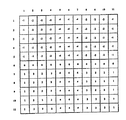
検査位置72に所在するレンズ74を透過した光ビームはイメージングサブシステム16によって受け止められ,これに対応した一連の信号が生成される。図1と2によれば,カメラケース50の内部,シャッター54の直後にピクセルアレー52が配置されるが,このピクセルアレー52は,多数の光センサー,すなわちそれぞれが入射光量に比例した電流を発生可能な光センサーで構成するのが好ましい。従来通り,ピクセルアレー52の光センサー,すなわち所定個数のピクセルが格子状の行と列とに均一配列されるが,この格子は,例えば約1000行と1000列の,すなわち約100万個のピクセルで構成すればよい。図8にこのピクセルアレーの一部の概要が描かれているが,各文字それぞれがアレーの各ピクセルを示す。
【0028】
イメージングサブシステム16の能力は,検査対象レンズ74すべての特定状態を識別するのに必要な分解能を超えていることが好ましく,例えば、0.012mmの対象物を識別可能なカメラを使用するとよい。映像エリア内の1,048,576個のピクセルによって14.495mmの視野がカバーされ,各ピクセルそれぞれが,0.01416mmの線状対象スペースをカバーする。従って3個のピクセルによって正確にカバーされるレンズの異常部位や穴等の最大直径が0.0425mmを超えなくなるため,この監視システムは,当該レンズを,一般に不合格と判定すべき最小欠陥よりも小さなものまで検出する能力を備えている。
【0029】
システム10の運転に際しては,カメラ46の焦点をレンズ74の周辺ゾーンに合わせるとよいが,この場合,映写レンズのフィールド深度の関係上,レンズ74の光学的中心ゾーンにもピントが合わされる。例えば視野レンジを,ピクセル分解能でのピクセル当たりの変量が0.000055mm,すなわち映像を横切る視野でのトータル変量が0.057mmになるように選定すればよい。またカメラ46は,989ピクセルが対象スペース14.000mmに等しくなるように調整するのが好ましい。このようにすれば,上記シングルピクセルにおいてピクセル当たりの分解能が0.014156mmに,すなわち映像を横断する全ピクセル1024個の視野が14.496mmになる。
【0030】
この分野の通常の専門家にはよく理解されるように,このサブシステム16には適当した任意のカメラを使用することができる。既に実用化されているこのシステム10の実施例によれば,カメラ46がニッコール(Nikkor0. 55mm標準レンズ装備のクラスI・コダック・メガプラス高解像度カメラであった。このカメラは1320×1035ピクセルのセンサーを持っているが,その中の1024×1024ピクセルだけが使用された。その理由は,コンピューターのメモリーは2進法で,1024が210 に相当するため,210 ×210 ピクセルエリア,すなわち1,048,576ピクセルによってデータを生成すれば,イメージメモリー内での取扱いが容易になるからである。
【0031】
このカメラのレンズアパーチャーはf/4,視野は1−495mmにセットされた(脱イオン水中のレンズ74の直径は約1+2mm)。カメラレンズの終端には10nmフルウエーブ・ハーフハイトウインドウ(full wave half height window) 付の アンドバー(Andover)帯域フィルターが装着されたが,これは波長550nmに中心が合わされている。そして発生し得るすべての色収差がこのフィルターによって除去されて立体的分解能が全般的に改善されるとともに,レンズ検査に対する光学的応答が,検査員の視覚応答に近似したものになる。またCCD検出器での赤外線も除去されるが,このことは,赤外線によってシステム全体の変調伝達機能が低下される恐れがあるので,有利なことである。
【0032】
プロセッシングサブシステム20は,イメージングサブシステム16,特にピクセルアレー52からの信号を受け取り,詳細を後述するプログラムに従ってこれらの信号を処理することにより,検査対象レンズの少なくとも一つの状況を見極める。より特定的に言えば,カメラ42のピクセルアレー52からの電気信号がイメージプロセッサー手段に伝達されるのである。そしてこのプロセッサー手段が,アレー52の各ピクセルそれぞれからの電流信号を,これに対応した一つのデジタルデータ値に変換し,この値を,当該電気信号を発信したピクセルのアドレスに関係したアドレスを有するアドレスロケーションに記憶させる。
【0033】
またサブシステム14と16の働きを協調ないしコントロールするのにサブシステム20も使用することにより,光源36を活かし,システム10を通過するレンズ74の動きに合わせてカメラ46を動作させるのが好ましい。すなわち,パレットが検査エリアに進入したとき,その存在をパレットセンサーによって検出させるのである。そしてこの信号が受信されると,イメージプロセッサー60が,その前のパレットから継続中のいずれのプロセスも完了させ,その結果を,PLCコントローラーと監視用コンピューターの両者に報告させるとよい。パレットがコンベア沿いに連続移動するとき,パッケージセンサーが当該パッケージを検知して信号を発信する。そしてこの信号によって,当該レンズが撮像専用位置に所在することが知らされる。
【0034】
パッケージ検出信号の受信に伴い,イメージ処理用ハードウエアがイメージ把握を開始し,合格/不合格を判定するために当該イメージを処理する。イメージ把握の一部としてストロボが発光され,レンズが照射される。レンズ合格/不合格の情報は,次のパレットがスタートされるまで記憶されるが,この時点で結果が報告される。ただしあり得ることではあるが,このような報告が受信されなかった場合,例えばセンサーがパレットを正しく検知しない場合,それ以降のパレットの送り出しは許容されない。パッケージ検出センサー信号は,パレット各側に8個のパッケージが見い出されるたびに発信される。
【0035】
またイメージプロセッシング基板が,レンズを何時映写すべきかを決定する。パレットがカメラの下を通過するとき,各パッケージのエッジが光ファイバーセンサーによって検出されるが,これに伴ってストロボが発光され,コンタクトレンズがカメラで撮影される。この撮影は,撮影信号をカメラに伝達することにより,イメージプロセッシング基板によって始動される。そしてストロボ発光後,カメラの記憶装置に記憶されたイメージが,プロセッサー基板の一つ,すなわちマスタープロセッサーとしての役目を担うプロセッサー基板のメモリーに伝達される。そしてこのマスタープロセッサーが,従属プロセッサーとしての役目を担う他の二つのプロセッサー基板のいずれが,現在受信中のイメージを点検し得る立場にあるかを判定する。そしてマスタープロセッサーは,当該イメージを処理すべき方の従属プロセッサー基板に指令を発し,ビデオバスからイメージデータを受け取るべきことを知らせる。すなわちこのマスタープロセッサーが各イメージの検査とその結果報告とをモニターする。
【0036】
レンズイメージを処理してその中心部の欠陥検査が終了すると,二つの従属プロセッサーがそのことをマスタープロセッサーに報告する。そしてマスタープロセッサーがこの情報を集め,二つのレポートを伝送するが,その一つが,受入れ/拒絶ロボットの動きをコントロールするPLCに送られる。このPLCは,先入れ先出し方式で各パレットを追跡するが,検査終了パレット上の各パッケージに対して直ちに判決を下す。また二つ目のレポートは監視用コンピューターに送られてデータが集積され,製造管理プログラムならびに生産計画立案者によって分析される。
【0037】
このシステム10には,適切な任意のプロセッシングユニットを使用することがてきるが,60a,60bおよび60cの各プロセッシングユニットは,例えばパーセプティックス社で販売されているIP−940イメージプロセッサーマシンのビジョンボードであればよい。
【0038】
好ましくはキーボード70aとビデオターミナル70bとを備えたホストコンピューター70がプロセッサー装置60に接続され,プロセッサーにインプットされる画像データやメッセージをディスプレーする。またこのプロセッサー装置60にはモニター66も接続されており,プロセッサー装置60に記憶されたデータ諸値に基づきビデオイメージがここで生成されるが,このモニター66は検査結果や集計値の表示にも利用可能である。モニター66は解像度の高いカラーモニターであることが好ましいが,これはやはりイメージボード60a,60bおよび60cに接続されているパーセプティックス社の高分解能ディスプレーカードHRD900でコントロールされる。またモニター66は,プロセッサー基板上のRS232コネクターによってプロセッサー基板に連結される。
【0039】
このシステムのオペレーターインターフェースは,ホストコンピューター70と高解像度モニター66とで構成されるが,このホストコンピューター70によってプロセッサー基板への接続とコミュニケーションとが実現される。またこのコンピューターのキーボードは,プロセッサー基板への情報インプットに用いられ,またホストコンピューター70のモニターのウインドータイプ・ビデオディスプレーが結果とステータスメッセージとを表示し,運転中に得られたこれらのイメージがこの高解像度モニター上にディスプレーされる。またステータスならびに結果に関する情報もこのモニターに表示される。
【0040】
図10では,レンズが毎回映写されるが,これは当該パレットの検査報告を伴って短時間だけ高解像度モニター上に現れるが,必要に応じ,任意のエラーメッセージを表示させてもよい。このモニター上の映像は,ビデオバスをコントロールする高解像度ディスプレーボード,HRDによって各所に広く伝達される。これはイメージプロセッサー基板,IP−940からイメージを受け取り,オペレーターの選択に従ってエッジもしくはセンターのカメラからのそれぞれのイメージをディスプレーする。すなわちHRDボードは,処理中のイメージをモニターしながらこれをリアルタイムでモニターにディスプレーさせるが,イメージの処理そのものには干渉しない。
【0041】
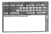
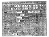
オペレーターからの命令やデータをプロセッサー装置60に伝達するのに,グラフィカルなユーザーインターフェースを用いてもよい。図11に,このグラフィカルユーザーインターフェースのメインウインドー,システム内のプロセッサー基板に対するシングルスクリーンコントロール機構が示されているが,このスクリーンは,ホストコンピューター,好ましくはサン(Sun) ホストコンピューターへの一つの命令,すなわちmachinename% ipmgr& の入力によって即時出現させるのが好ましい。このスクリーンのターミナルによれば,ホストコンピューターのウインドー環境にウインドーを増減させることが可能になる。ipmgrウインドー頂部の ”terminals”ボタンを選択すると,図12に示されているように新しいウインドーが現れる。そしてこのウインドーによれば,オペレーターが各イメージプロセッサー基板それぞれに対してホストウインドーをオープンさせることができるようになる。それぞれのターミナルウインドーを開くと言うことは,選定された各プロセッサー基板それぞれに対してダムターミナルを接続するようなものであり,パレットの合格/不合格報告やデバッギングあるいは試験的状況に対して利用するとよい。
【0042】
当然のことながら,サブシステム20には上記以外の入出力装置を追加してオペレーターや分析者がプロセッサー基板やコントローラー24と連携できるようにすることができる。例えばプロセッサー基板にプリンターを接続することにより,プロセッサー基板からこれに送られてくる特定データやレポートをプリントさせることができる。
【0043】
ただしホストオペレーティングシステムを介した幾つかの方法によってプリントアウトさせるのが好ましい。マスタープロセッサーからのスクリーンレポートは,ファイルすべきスクリーン情報を先ず保存したあと,後刻これをプリントアウトすることにより,プリントするとよい。すなわちプリンターは,情報がスクリーンからスクロールオフされるときにこれをプリントするのに使用することができる。レンズの性情に関するすべての情報が一斉に監視用コンピューターに送られるが,このコンピューターは,データを消化して生産レポートをアウトプット可能なものであることが好ましい。
【0044】
図9では,好ましい様式としてイメージ処理用の全ハードウエア,ホストコンピューター,モニターおよび無停電電源装置がシングルキャビネットの中に収容されている。外部からキャビネット内に引き込まれるシステム内のすべての配線は,先ず仕切り板を通り抜ける。
【0045】
前述したように,レンズ74が検査位置72を通過するたびに光線がレンズを透過してピクセルアレー52に入射され,このアレーの各ピクセルがピクセル上の光の強さに対応した電流を発生する。そしてこれらの電流がデジタルデータ値に変換されるが,これらのデータを先ずプロセッサー装置60内に記憶させたあと処理し,当該レンズが使用に適するか否かを判定するのが好ましい。この検査プロセスの好ましい実施例では,レンズの不在,エッジの欠損,エッジの傷,表面の傷,はみ出し,穴,凹み,偏心やざらつきが検出され,かつこれらの態様を分析して当該レンズをはねるべきか否かが判定される。
【0046】
図13には,好ましいレンズ検査プロセスの主要ステップが示されている。これの第1ステップでは,レンズがピクセルアレー上部の映写位置に配置され,不良レンズがテストされ,かつレンズの外縁が型とりされる。レンズがこれら最初の3ステップのいずれか一つでも落第すると,当該レンズは自動的に拒絶されるが,これら3ステップで合格すると,アルゴリズムがレンズの偏心を判定し,パッケージの合いマークを処理したあと,レンズの周辺ゾーンに引き続き中心ゾーンそれぞれの欠陥が探索される。そしてこのステップにおいてなんらかの欠陥が検知されると,当該レンズを受け入れるべきか,それとも拒絶すべきかが,アルゴリズムによって判定される。
【0047】
イメージ内へのレンズの配置
このあと,引き続きレンズの生イメージがインプットされるレンズ検査プロセスの初期ステップでは,視野の中へのレンズの位置決めが行われなければならない。しかし従来のやり方での問題点の一つとして,傷ついたり,破損したレンズがレンズ不在として誤分類されることが挙げられる。そしてレンズの破片がレンズ不在として分類されると,レンズの検査が終わったあと,キャリアの窪み86から脱イオン水を排出させるときに問題が惹起される恐れがある。例えば窪み86内にレンズの大きな破片が存在することが認識されなかったら,この破片が排水ノズルの排出弁を閉塞し,工程の進捗を妨げる恐れがある。
【0048】
しかしこのシステム10によれば,レンズ本体だけではなく,レンズの破片も発見されて破片として分類され,これが存在するパッケージを手で取り除くことができるようになるので,上記のような問題が解決される。もしパッケージの中にレンズの大きな破片が存在していれば,この検査システムは制御PCL24に信号を送って搬送サブシステム12を停止させるとともに,オペレーターに対して当該パッケージからレンズの破片を取り除くように警告する。
【0049】
一般にピクセルアレー52上に結ばれる映像は,レンズそのものであったり,あるいはその破片であり得るが,これが水平ならびに垂直の各探索ベクトルを用いて探索される。これらの探索ベクトルにより,イメージ勾配が下式(1)に従って分析される。
【数1】

この勾配Gは,探索ベクトル沿いの各ピクセルについて計算されるが,この勾配計算値の大きさが,パラメーター ” E_findThr”で定まる特定しきい値を超えたら,レンズが発見されたらしいことを意味する。この式(1)は,XおよびYの各 Sobelオペレーターの絶対値を取り入れることによって形成されるが,総合イメージコンボリューションを包含した通常のオペレーションとは異なり,この変形Sobelは,探索ベクトル方向にのみ進行する。すなわち傾斜の大きさGは,式(1)によって定まる総量となり,また勾配の方向,すなわち符号によって影響されない。この結果,正負いずれのエッジ勾配も検出可能となるので,より敏感にエッジが検出されることになる。しかも式(1)は,水平および垂直両方向のエッジ検出探索ベクトルに対して使用可能であるが,これらのベクトルが,イメージエリアの少なくとも50%をカバーすることが好ましい。
【0051】
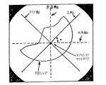
図14と15では,水平および垂直それぞれ10本の一連の探索ベクトルがエリアを潜在的に横断しているが,これら各ベクトルは,互いに等距離を隔てており,かつイメージの4隅にそれぞれ存在するダークエリアに引っ掛からないように配列されている。これらの図には,探索ベクトルの方向が矢印で,また掃引順番が数字で,それぞれ示されている。
【0052】
これらのベクトルはこの所定の秩序に従い,レンズが特定されるまで,すなわち全ベクトルの掃引が完了するまで探索される。そして当該レンズが特定されたら,探索ベクトル沿いの探索を打ち切るのが好ましい。例えば,正常なレンズは最初の探索ベクトル沿いの探索期間中に発見されるのに対し,不良レンズを発見するためには,殆どすべての探索ベクトル沿いに探索する必要があり得る。
【0053】
先ず対象物を特定したあと,次にレンズ検出を確認するためのテストが実行される。この確認テストでは,発見済対象物の輪郭がなぞられるが,これには,これに関連した適当な任意のやり方を用いればよい。例えば8個の結びつき分析とでも言うべき技法を用いてエッジを追跡すればよい。この技法では,特定対象物のエッジ上に存在する最初のピクセルが発見されたら,このピクセルに隣接する8個のピクセルを,2番目のエッジピクセルに向かって均一方向に探索する。そしてこの2番目のエッジピクセルが発見されたら,これが当該対象物のエッジ上に存在するものと見なされる。そしてこのプロセスが繰り返され,この2番目のエッジピクセルに隣接する8個のピクセルが,第3エッジピクセルに向かって均一方向に探索される。エッジ追跡もしくはオブジェクト追跡とも言うべきこのプロセスは,エッジの終端が発見され,このエッジがそのオリジナルピクセルに戻る前に所定個数のエッジピクセルが発見されるまで,すなわち識別されたこれらのエッジピクセルによって形成されたエッジが閉じたループを描くようになるまで,より特定的には,このエッジが当該対象物の最初のエッジピクセルに戻るまで,繰り返される。
【0054】
図16Aと16Bに,この8個の結びつき分析の詳細が描かれているが,ここでは周囲の各ピクセルの探索をより良く図示するため,各ピクセルが点で表現されている。図16Aには,対象物のエッジ上に存在することが識別された最初のピクセルが,Pi,j で示されている。そして所定のしきい値を上回るいるグレーレベルを有するピクセルに対し,このPi,j 直上のピクセルを始点として反時計回り方向に8個の隣接ピクセルが探索される。このテストにミートして発見された最初のピクセルが次のエッジピクセルであると考えられるが,図16Aの例では,ピクセルPi,j+1 がこれに相当する。
【0055】
次のステップが図16Bに描かれているが,ここでは,所定のしきい値を上回るグレーレベルを有し,かつこの直前に実行された探索では中心になっていなかったピクセルに対し,Pi,j+1 の直上のピクセルを始点にしてPi,j+1 に隣接する8個のピクセルが反時計回りに探索される。そしてこのテストにミートして発見された最初のピクセルが次のエッジピクセルと見なされるが,これが図16Bの例では,Pi,j+2 で示されている。そしてこの追跡プロセスが,この探索がピクセルPi,j に戻り,かつ輪郭がその原点位置にまで戻る前に所定個数の輪郭ピクセルが出現するまで,もしくは所定ピクセル周りの探索が,なんらかの次のエッジピクセルの識別に失敗するまで,継続される。
【0056】
この追跡手順の期間中,これらのピクセルが対象物の輪郭の上またはその外側かを判定するのに勾配の大きさを利用するのが好ましい。勾配の大きさの計算法は,探索ベクトルルーチンに際して用いられるそれと同一で,やはり式(1)によって求められる。またこの追跡期間中に用いられるしきい値も,探索ベクトルによって用いられるそれと同一であり,パラメーター ”E_findThr”によって特定される。
【0057】
対象物追跡期間中,特定個数の輪郭ピクセルが追跡され終わるまで,その輪郭の始点位置に遭遇しなければ,当該対象物はレンズに間違いないと見なされる。しかし輪郭ピクセルが所定個数に達するまでに始点に出会うと,当該対象物はレンズと見なされず,ノイズと解釈される。この実証テスト期間中に適用されるレンズ輪郭の最小長さは, パラメーター”B_cont_cnt”で与えられる。もし1本のベクトル沿いの探索期間中にノイズオブジェクトに出会ったら,このベクトル沿いの探索は打ち切られ,次のベクトル沿いの探索に引き継がれる。そしてレンズが発見されるまで,もしくはすべてのベクトルがトライされ終わるまで,この手順が繰り返される。図17Aに,仮想レンズ検出の探索例が示されているが,ここではレンズが特定される前にノイズオブジェクトが発見されている。また図17Bに示されている仮想レンズ検出の探索例では,損傷レンズ特定前に,二つのノイズオブジェクトが発見されている。
【0058】
全探索ベクトルがトライされ終わってもレンズが発見されなければ,レンズは喪失されたものと判定される。そしてこの結果が報告され,プロセスが中断される。しかしレンズが発見された場合には,最初にレンズが検出されたイメージ座標が保持され,プロセスが更に続行される。
対象物の形態的性状を分析してこれが不良レンズであるか否かを判定するのに先立ち,更に次の二つテストを実行するとよい。先ず,対象物周囲を追跡中,このトラッキングがイメージメモリーの外側境界からはみ出すようなら,この被験レンズはその一部が視野から外れ,不合格になる。このような場合には,当該イメージに関するプロセスは打ち切られる。次に,対象物周囲を追跡中,輪郭ピクセルの個数が最大値を超えたら,当該被験レンズは1個のレンズとしては大きすぎることになり,このレンズも不合格となる。
【0059】
破損したり傷ついたレンズに対するテスト
このテストにおいてプロセスが継続されたら,当該被験レンズは傷ついているか,もしくは健全かのいずれかに仕分けられる。トラッキング途中でレンズのスターティング箇所に出会ったら,当該対象物はその外形全体にわたって横切られたものと見なされる。傷ついたレンズに対する形態テストは,スターティングピクセルに出会うか,もしくは輪郭ピクセルの個数が許容最大値を超えるか,のいずれかの条件によって始動される。
【0060】
このアルゴリズムの好適実施例では,当該対象物が傷つけられているか否かを判定するのに,いわゆるエロンゲーションおよびボックスサイズの限定と言う二つの主要なテストが実行される。エロンゲーションテストは,大きな破片が脱落ないし喪失されてもはやユニタリ離心率を有する円形の対象物とはほど遠くなってしまったレンズを識別ことに主体を置いて設計される。またボックス限定テストでは,エロンゲーションに関するチェックが行われるが,特に,ともかく円形ではあるが傷つけられたレンズを識別するのに適用される。
【0061】
上記二つのテストでは,いずれもレンズの輪郭全体のトラッキングによって得られた座標情報が利用されるが,このトラッキング技法は,レンズ検出を実証するのに用いられる技法と同一である。このトラッキングプロセスでは,式(1)で求められる勾配値を用いることにより,当該ピクセルがレンズ輪郭の上またはその外側のいずれに存在するかが判定される。またレンズの輪郭沿いの追跡には8個の結びつき分析法が用いられ,またパラメーター”C_findThr”によって勾配値が特定される。
【0062】
トラッキングの実行に際しては,輪郭内の各ピクセルの行および列の各位置の一連の記録が保存されるが,この輪郭トラッキングは,1)トラッキングがイメージメモリーからはみ出す,2)輪郭ピクセルの個数が許容最大値を超過する,あるいは3)レンズ輪郭の始点に出会う,と言う三つの事象の一つが発生するまで継続される。
【0063】
トラッキングがイメージメモリーからはみ出したら,当該レンズは,その一部がイメージ視野の外側にあるものと見なされ,失格する。そしてこの結果が報告されてプロセスが打ち切られる。レンズの始点と出会ったり,あるいは輪郭ピクセルの個数が許容最大値を超えた場合には,エゲーションや境界エリアすなわちボックス限定に関連した形態的性状が抽出され,傷ついたレンズの存在の有無が判定される。
【0064】
エロンゲーション値は,下式(2)によって与えられる:
【数2】
このエロンゲーションテストでは,対象物の最小慣性モーメントに対する最大慣性モーメントの比の測定値が求められる。当該対象物の最小寸法に対する最大寸法の比が大になるにつれ,このエロンゲーションの値が大になり,またコンパクトになればなるほど,この値が小になる。例えば対象物が円形であれば,理論的にエロンゲーションの値が最小になるのに対し,棒状ないし線状であれば,エロンゲーション値がこれよりも大になる。
【0066】
このエロンゲーションを計算するため,輪郭の全ピクセルに対する座標データについてパスが作成され,このパスによって水平および垂直の各慣性モーメントが計算される。下式(3)と(4)にこの計算式を示す。
【数3】
【数4】
これら二つの情報から,対象物の主軸の成す角度が,下式(5)によって求められる。
【数5】
決定されたこの主軸の角度を用い,全ピクセルの座標データにまたがる最終パスを作成することにより,主軸ならびに下位軸まわりの慣性が下式(6)および(7)を用いて計算される。
【0070】
【数6】
yi =レンズ外郭沿いに発見されたi 番目のピクセルの行座標で,レンズ輪郭上の全ピクセルについて合計値が求められる
x’avg =主軸沿いの対象物セントロイド
【数7】
yi =レンズ外郭沿いに発見されたi 番目のピクセルの行座標で,レンズ輪郭上の全ピクセルについて合計値が求められる
y’avg =下位軸沿いの対象物セントロイド
【0071】
そして前掲の式(2)によってエロンゲーションが計算されるが,この計算値をパラメーター”C_elong”によって特定される値と比較することにより,当該レンズの傷の有無が判定される。例えばエロンゲーション計算値が”C elong”よりも大であれば,当該レンズには傷があると見なされ,プロセスの進行は打ち切られる。
【0072】
図18に,エロンゲーションの特色に関する幾つかの専門用語を示す。
レンズ対象物に対してボックス限定の特色が計算されるが,ボックス限定とは,ボックスを,対象物の最大と最小の垂直ならびに水平の各軸をベースにして被験レンズを保持するのに丁度よい大きさに合わせることである。このようなボックスは,被験レンズの実対象エリアに対して極めて近似的に作用することが発見されている。このテストは,エロンゲーションテストでは識別されない恐れのあるような,傷ついたレンズを識別するために実施される。詳述すれば,傷ついたレンズは,一見,円形であるかのように見受けられかねないように変形されていてるため,エロンゲーションテストでは識別不能なこともあり得るであろう。このボックス限定テストは,傷ついてはいるがともかく円形なレンズは,正常サイズのレンズよりも一般に小であると言う特徴を利用したものである。このボックスは,対象物のセントロイドを通過する水平および垂直の各軸沿いにオリエンテーションされる。図19にこのテストのコンセプトを示すが,このテストは下式(8)で定義される。
【数8】
そしてこのボックス制限計算値が,パラメーター”Cーbdbox”によって特定された値と比較されるが,例えば計算値が”c−bdbox”よりも小なら,当該レンズには傷があると見なされて失格し,プロセスの進行は打ち切られる。
【0074】
モデルレンズの外縁
被験レンズがエロンゲーションとボックス制限の両テストに合格したら,傷ついたレンズ検出用の2番目の技法が実行される。図20においては,対象物のエッジ上の約60°の間隔を隔てた6個のデータポイントを用い,対象物トラッキングデータから6個の円形モデルが定義される。すなわち,連続した3個のデータの各セットを用いてそれぞれ独自の円が定義されるが,データポイント〔1,2,3〕,〔2,3,4〕,〔3,4,5〕,〔4,5,6〕,〔5,6,7〕,〔5,6,1〕および〔6,1,2〕がそれぞれセットになる。この円形モデルは,パラメーター”B lens dia”によって特定される半径に最も密接にマッチした半径を持ち,レンズ外縁モデルとして使用される。
【0075】
これら各円形モデルについて,円を定義するのに用いたデータポイントを最初にチェックし,これらが互いに接近し過ぎていないことを確かめることが好ましい。と言うのも,レンズにその輪郭の全周360°の連続性を損なうような傷が含まれていると,このようなことが起こりうるからである。互いが余りに接近し過ぎたデータポイントを含んだデータセットによれば,誤ったモデルがもたらされる恐れがあるので,このようなデータは無視するのが好ましい。
【0076】
被験レンズの輪郭沿いの各ピクセルを,レンズエッジとして用いられる理論モデルと対照する。そして極座標探索表を用い,各輪郭ピクセルの位置を当該エッジを中心とした半径と角変位量で書き換える。もし任意のピクセルの距離が,レンズエッジとして用いた円形モデルの半径の90%よりも小であれば,当該ピクセルは大きな傷の一部あると見なされる。そして,同じ傷の一部であると見なされた各ピクセルグループの測定値が角度で表現されるが,この傷の始点と終点とによってこれがパラメーター”C_badtear”よりも大であることが判明したら,当該レンズは傷があると見なされ,失格する。図21には,レンズの傷の広がりを判定する技法として,距離変位量を利用するコンセプトが描かれている。
【0077】
レンズを巡る輪郭が途中で途切れている場合,この輪郭トラッキングが反対方向,すなわち−a方向へ,いわゆる折り返し状態になったとき,当該傷の始点と終点とがアルゴリズムによってマークされる。すなわち初回の折り返しに際して検知された箇所が,傷の始点としてマークされる。このポイントでトラッキングは逆行状態になり,レンズ輪郭の内側をフォローするようになる。しかしレンズの他の側からは,途切れのオリジナルポイントに再度遭遇することはあり得ないので,次の折り返し状態では,途切れの原因となった傷の反対側が検出されるものと推論して差し支えない。
この技法は,レンズの中で途切れの原因となった傷のひどさの程度を判定すると言う課題を解決するのに利用される。図22にはアルゴリズムのこの部分のコンセプトが図示されている。途切れが傷の中に発生している場合には,この傷の区間が,レンズの傷の始点と途切れ箇所との間の部分を含むように調整されるので,傷の程度がより正確に表現されるようになる。
【0078】
当該レンズがトラッキングの途中でイメージメモリースペースからはみ出したり,輪郭ピクセル個数,エロンゲーションやボックスサイズ制限を超えて失格しなければ,当該レンズは健全であると見なされる。しかし図13に示すように,このレンズはまだ合格に分類されず,この時点でレンズであることが判明し,イメージ検査のこれ以降のプロセスに受入れ可能であると,識別される。次のステップが心ずれ(ディセントレーション)のテストである。
【0079】
ディセントレーション
周辺ゾーンに対しては,例えば0.270mmもしくはそれ以下の幅が許容される心ずれを伴ったレンズは,不合格と見なされることがある。レンズはパッキング用塩類溶液の代わりに脱イオン水の中で検査されるので,レンズはまだその最終的フルサイズにまで膨張していない。従って先ず近似的には,これの周辺ゾーンを等方性の媒体の一部と見なして差し支えないが,このことは,脱イオン水がパッキング用塩類溶液に置き換えられてレンズが膨張するとき,レンズは径方向に膨張して環状帯域の幅が増加するが,これはレンズ全体の直径が増加したのと同様であるとの事実に立脚する。
【0080】
パッキング溶液中でのレンズ周辺ゾーンの最終的幅と,脱イオン水中での定常状態におけるこのゾーンの幅との相互関係は,下式(9)で表される。
【数9】
レンズの最終直径Df を,例えば1−200mmに,また脱イオン水中での定常状態の直径Dw を895ピクセル,すなわち1+670mmに設計したとすれば,このレンズの線膨張係数ζは,上式(10)により0.12076になる。この値を式(9)に代入すると,下式が得られる。
PZf =PZw (1.12076) ・・・(11)
【0082】
システム10に使用したあるタイプのレンズの外径が1−200mm,またレンズ背面の光学ゾーンの直径が1,000mmであると,周辺カーブ沿いの全体の線間距離はこの二つの値の差,すなわち*200mmに,またレンズの周辺ゾーンの幅PZf はその半分,すなわち600ミクロンになる。このPZf の値を式(11)に代入すると,PZw の値が下式(12)で,次のように求められる。
【数10】
このように先ず近似的には,周辺ゾーンの幅PZw は535μmと見積もられるが,実際の値は580μmである。つまりモデルでは周辺ゾーンの幅が8%程度過小評価されるが,このことは,例えばパッキング溶液中ではレンズが非線形に膨張するか,あるいは眼科用レンズ作成用モデルは,光学ゾーンの直径に対して異なったターゲット寸法を持つと言う事実に起因するものと思われる。
このシステム10に用いられるアルゴリズムの優先的実施例では,周辺ゾーンの幅が332μm未満のいずれのレンズも拒絶される。周辺ゾーンの最小幅に関するパラメーター”C_minPZdist”の値は332である。
【0084】
レンズの心ずれを判定するため,レンズの外縁と周辺ゾーン/中心ゾーンのエッジとの間で比較が行われ,両エッジが円形であり,かつ各エッジに局限された偏差は,心ずれの最終判断にとって重要なものではないことが確かめられる。そしてレンズ発見動作期間中に決定される円形モデルを利用してレンズ外縁の特徴が把握される。そしてこのレンズ外縁モデル上でほぼ0°,180°および270°の3か所のデータポイントを選出し,これを三つのウインドーの基準位置として利用する。これらのウインドーはレンズ外縁モデルの内部に配置され,周辺ゾーン/中心ゾーンの境界を発見するのに利用される。図23にこれらのウインドーの配置を示す。
【0085】
各ウインドーそれぞれの内側では大型の一次元エッジオペレーターが操作されるが,図24と25に,垂直ならびに水平の各エッジをそれぞれ拡大するのに用いる勾配(グラジエント)マスクを示す。0°と180°の各ウインドーには図24の垂直エッジマスクが,また270°のウインドーには図24の水平エッジマスクが,それぞれ使用される。
【0086】
次に各ウインドーの長手方向沿いにエッジの濃淡が測定されるが,0°と180°の各ウインドーに対しては,各列がそれに関係したエッジの濃さを持つ。そして処理中の列とこの列の両側の列との各勾配値の和が,当該ウインドー内の各列用にコンパイルされる。そしてどの列に最も濃いエッジが含まれているかを判定するため,これらすべてのエッジの値にまたがるパスが作成される。図26に処理済ウインドーの代表と,得られたエッジ濃淡のヒストグラムとを示す。
0°および180°の各ウインドーについては,このヒストグラムから得られた上記ピーク列によって周辺ゾーンと中心ゾーンとの境界が定義されるものと見なされる。各ウインドーの行の中心が,この周辺ゾーンと中心ゾーンとの境界上の二つのデータポイントを定義する行座標に対応する。式(11)と(12)にこのヒストグラムのコンパイレーションと分析とを式の形態で示す。
【0087】
【数11】
このコンセプトによれば,270°のウインドー内の処理は,他の二つのウインドーのそれと同様であるが,このウインドーに対しては,処理対象エッジが垂直ではなくて水平なので,すべての操作が90°捩回される。ウインドーの次元を旋回させ,水平エッジマスクを使用して行から行へとエッジ濃淡のヒストグラムをコンパイルし,最終的に周辺ゾーンと中心ゾーンの境界の行の値が求められる。このウインドーの列の中心が,周辺ゾーンと中心ゾーンの境界上のデータポイントを定義する列座標に対応する。式(13)と(14)にこの分析を式の形態で示す。
【0089】
【数12】
この周辺ゾーンと中心ゾーンの境界の三つのデータポイントによって円形モデルが計算される。
最小ならびに最大の心ずれを発生させる軸の角度が,レンズの外縁エッジモデルの中心と周辺ゾーン/中心ゾーンモデルの中心との変位量から計算されるが,この相互関係を式(15)に示す。
【数13】
この角度が決まりさえすれば,この角度における周辺ゾーン/中心ゾーンのモデルとレンズ外縁モデルの各ポイントの行と列とが計算される。そしてこの二つの距離の差が最小心ずれ値になる。もしこの値が,パラメーター”C minPZdist”よりも小にならなければ,当該レンズは心ずれのために失格する。図27にこの心ずれ計算の幾何学的相互関係を示す。
【0092】
チック・マ−ク
レンズが分散試験を通過すると、水分除去中に摩擦接着に使用されているチック・マ−ク帯域、すなわちTMZとして知られるパッケ−ジ領域が処理される。TMZ処理の目的はTMZの総体的に低い強度を中心帯域、すなわちCZを取り囲む平均的強度輪郭に配合させることにある。TMZがCZに一度配合されるとCZ全体が不均一性の処理を受けることができる。TMをCZに配合する手法は対象情報をTMZ内に保持するようにして行なわれることが好ましい。あるいは、TMZはTMZに欠陥が存在することを示す不均一性のためにCZの残りの部分とは区別して評価できるだろう。それでも、TMZをCZに配合することは好ましいし、そのときCZ全体を一つの共通した欠陥の強度のしきい値で検査することが好ましい。
【0093】
パッケ−ジ中心とレンズの中心とは映像視野内で同一でなければならないことはない。しかしながら、これらの中心が一致しなくても、パッケ−ジ・チック・マ−クは映像内の正規のパタ−ンに現われる。一般的には、これらのチック・マ−クの位置の違いは映像から映像への数画素だけの変化でしかなく、たとえば28図は一つの映像内のチック・マ−ク・パタ−ンの概略の位置を示している。これらのチック・マ−クの位置が非常に近いため、TMZを見付けるための好ましいサ−チ・ル−チンはサ−チの範囲を映像内に比較的小さい領域に限定してしまう。特に、映像の総計は1,048,576個の画素を含むことができ、他方最初のチック・マ−ク用の典型的サ−チ領域は約3,000個の画素を持つことができる。
【0094】
一つの好ましい実施態様を用いると、最初のTMZは当該TMZが位置すると期待される比較的大きい領域をサ−チすることにより見付けられる。たとえば、29図は最初のチック・マ−クをサ−チするサ−チ領域を図示している。一度TMZが一つ見つかると、そのTMDの位置は他のTMZを見付けるために役立つ。特に、より小さいがもっと正確にサ−チ領域の他のTMZを探すための最初のTMZの位置に対する相対位置が確認される。たとえば、第二、第三、および第四番目のチック・マ−クに対するサ−チ領域面積的には400画素にすぎない。図30はTMZの面積を定めるために使ってよいサ−チ領域の一例を示している。
【0095】
さらに詳しく述べると、好ましいチック・マ−クの取り扱いは左側の水平チック・マ−クを位置させるためのかなり大きい矩形領域をサ−チすることにより始まる。そのサ−チ領域の場所を決める行および列の基準点はバラメ−タ”C_r_tickofst”および”C_c_tickofst”によりそれぞれ指定される。おびただしい数の等間隔に置かれたの列サ−チ・ベクトルがそのサ−チ領域を横切る。サ−チ・ベクトルは一次元勾配の大きさがチック・マ−ク境界の存在を示すまで頂上から麓まで横切る。勾配の計算は(16)式で定義される。
チック・マ−ク・サ−チ勾配=abs(Pi−1 , j−Pi,j) (16)
【0096】
勾配の大きさはパラメ−タ”C_tickhthr”見つかったしきい値と比較される。もし、ある特定のサ−チ・ベクトルに沿ってサ−チされながら、計算された勾配がそのしきい値より大きいか等しい場合、チック・マ−クの頂上境界がそのサ−チ・ベクトルに沿って見つかる。もし頂上境界が見つかると、サ−チは同じ列に沿って麓から頂上に向かってそのチック・マ−クの麓の境界を位置させるために行なわれる。このサ−チ・ベクトル・サイクルはそのサ−チ領域内のすべてのサ−チ・ベクトルに対して行なわれ、たとえば図31は左水平チック・マ−クを位置させるために使ってもよいサ−チ領域サ−チ・ベクトルを示す。
【0097】
一つのチック・マ−クの領域にあるすへてのサ−チ・ベクトルから得られたチック・マ−クについての境界情報は解析されそのチック・マ−クの行方向重心が得られる。チック・マ−クとしては幅が大き過ぎ厚みが薄過ぎる対象境界を検出したサ−チ・ベクトルは捨てることが望ましい。好ましくは、何の対象も見付けなかったこれらのサ−チ・ベクトルも捨てることである。次に、残りのベクトルがチェックされ潜在的チック・マ−ク対象を確認した連続サ−チ・ベクトルの最長セグメントを決定し、確認された最長対象がそのチック・マ−クとみなされる。この手順はチック・マ−クをより小さい対象あるいは項目をノイズとみなして後者と区別したり、サ−チ領域内で出くわすかもしれないレンズの欠陥と区別するように設計される。行重心は最長確認セグメントのサ−チ・ベクトル境界から計算され、そして図31はまたこのサ−チ・ベクトル・プロセスおよびサ−チ・ベクトルと行重心決定との関係も示している。
【0098】
次の段階はそのチック・マ−クの列境界を確認することである。これを行なうために、二つのサ−チ・ベクトルがそのチック・マ−クのすでに決定された行重心に沿ってサ−チ、あるいは横断される。これらの二つのベクトル最長確認セグメントの列平均から外側に向かってサ−チされる。これらのベクトルの一つはそのチック・マ−クの左側の境界を見付けるため左方向へサ−チされ、片方のベクトルはそのチック・マ−クの右側の境界を見付けるため右方向へサ−チされる。グレイレベルのしきいはチック・マ−クに見つかった欠陥が原因で勾配情報を誤らせるかもしれないためそれらのチック・マ−クの列境界を確認する目的のために使うことが望ましい。さらに、一つのチック・マ−クにある複数個の欠陥はそのチック・マ−クの残りの部分より暗く見える。そのために、グレイレベルのしきい手順を使ってサ−チを行なうとそのチック・マ−ク内部の欠陥をそのチック・マ−クの境界と誤解し、グレイレベルのしきいは一つのチック・マ−クをより明るい取り囲んだ領域と区別することができる。
【0099】
好ましくは、一つのチック・マ−クの行境界を確認するために使うグレイレベルのしきい値をそのチック・マ−クを取り囲む二つの領域の平均グレイレベルの固定割合として計算することである。一例として、図32はグレイレベルのしきい値の計算に使えるチック・マ−クの二つの近傍の領域を示している。一つの画素がこのしきい値より大きいかまたは等しい列サ−チ・ベクトルに沿って出くわすと、境界が確認される。そのとき、そのチック・マ−クの列重心はこれらの二つの境界から計算される。
【0100】
あるいは、勾配計算はチック・マ−クの左右の境界確認に使うことが可能であろう。これを行なうには、たとえば、そのチック・マ−クの右端を見付けるために境界領域の右側からサ−チ・ベクトルを左方向に横切ってもよい。勾配の大きさは(1)式にしたがって計算してもよく、また勾配がパラメ−タの”C_tickwthr”で指定したしきい値より大か等しい場合、そのチック・マ−クの右側の境界が見つかる。そのとき、同様に境界領域の左側から右方向にサ−チ・ベクトルを横切ってチック・マ−クの左側の境界を見付けてもよい。図33は一つのチック・マ−クが行ベ−スでどのように処理されるかを概念的に示している。
【0101】
一度TMZが決められると、それはオフセット変換と呼ぶ手順を使って周囲の映像情報と配合される。この変換は本質的にはそのチック・マ−クのグレイレベルを行ベ−スで近傍の領域と配合して取り込まれるレベルへ昇格させる。この手順を使うと、欠陥情報は維持され、欠陥のための変換された領域の解析は後でレンズの中心地帯のすべての他の部分に対して使われた同じ手法で行なわれる。
【0102】
さらに詳細に述べると、この手順では、TMZに近い二つの地域に対するグレイレベルは平均される。これらの二つの領域はたとえば図32に示されるチック・マ−クの重心決定中に使われた領域と同じてもよい。差の△row はTMZの外側の平均グレイレベルとチック・マ−ク行の各々との間で計算され、そのTMZの内部の各々の行に対しては△row の値が当該列に沿って各々の画素の値に加えられる。ある欠陥を含んだ一つのTMZ行に対するこのオフセット変換の結果は図34に示されている。この図が示すように、レンズのピンホ−ルの欠陥の映像は残されるが、TMZそれ自身はそのTMZを囲んだ映像の近傍領域に取り込まれている。変換プロセスのこの属性のため、そのTMZをCZ検査手法によりCZの一部分として画一的に調べてもよい。
【0103】
あるいは、一つのTMZを、線形オフセット変換を使うだけでなく、このような変換の前にそのTMZ内の画素の利得を増加させるように処理してもよい。この方法はTMZ内の欠陥を検出する検査手法の能力を改善につながるかもしれない。TMZにある利得要因をオフセット値△row を決定する前に掛けるとTMZ内の欠陥対象の勾配を増加させるだろう。しかしながら、これはTMZをより問題化する逆効果を招くかもしれない。
一度行と列重心が見つかると、変換は当該”チック・マ−ク”に関して行なわれる。その変換はその当該”チック・マ−ク”を取り囲んだ小さい矩形領域に限定されその当該”チック・マ−ク”の重心に集中される。境界領域の高さ(短寸)と幅(長寸)とはそれぞれ”C_tickhgt”および”C_tickwid”で指定される。
【0104】
他の三つのチック・マ−クは同様の方法で見つかり処理されるかもしれない。好ましくは、こられの三つのチック・マ−クはこれらの始まり位置が左水平チック・マ−ク重心から参照されるからこれらのサ−チ領域はそれぞれ最初のチック・マ−クに対するサ−チ領域よりいくぶん小さいことである。また、上下方向のチック・マ−クに対して、操作はチック・マ−クの長寸は列方向の代わりに行方向に向いているから90度回転される。たとえば、図30は他の三つのチック・マ−クを見付けるために使ってもよいサ−チ領域を示している。
【0105】
左水平チック・マークを使った場合、そのチック・マークのグレイ値は欠陥を検出しない。チック・マ−クはこれらをレンズ中心領域解析で使った手法で正しく取り扱うことができる一点に対して前処理される。この方法では、チック・マーク彼ら自身欠陥とはみなされず、一つのチック・マ−ク内に重なるか横たわっている本当の欠陥とみなされる。
【0106】
中心領域におけるホ−ルおよびマ−ク
コンタクト・レンズのホ−ルおよびマ−クの典型はコンタクト・レンズの映像の中心領域内に暗い斑点として現われる。そのような特徴は勾配サ−チ手法を使って白色背景とは見分けがつくかもしれない。しかしながら、CZにおける対象を定義するための勾配サ−チは実行に比較的多くの時間を取るだろう。映像全体が1,048,576画素からなっているために、約2千万回の操作が映像全体をテストために必要だろう。
【0107】
レンズの中心領域は周辺領域に対して内部にあるレンズのすべての部分とみなされており、図35はこの領域の位置を示している。この領域に対する実際の境界は好ましくは分散計算中に導かれた周辺領域/中心領域エッジのモデルから定義されることである。
【0108】
しみの分析の変更版が欠陥検出の手段として使われている。以下に論じる周辺領域の分析のように、中心領域のしみ分析はセグメント対象に対して八連結分析を使っている。しかしながら、周辺および中心領域におけるしみ分析を実施する場合には二つの重要な違いが存在する。中心領域では、前景対象を背景から区別するために使う画素特性は厳密に勾配の大きさである。この大きさは(17)式で定義される。
【数14】
もし画素の勾配の大きさがパラメ−タ”C_czbinthr”で指定されたしきい値より大きいか等しい場合、その対象は前景とみなされる。
【0110】
第二の違いは中心領域ではしみ分析は処理された領域が疑似サンプリング方法を使う。一つ置きの行と一つ置きの列の画素はしみ連結分析で使われる。勾配計算は、しかしながら、上記の(17)式で述べたように、処理されつつある画素の実際の隣にある物を使う。図36はサンプリングと勾配計算に使われる近傍を示している。
【0111】
一度映像にフルパスを行うと、見つかったそれらの対象の寸法が計算される。パラメ−タ”C_czminblob”で指定された対象寸法を超えたそれらの対象は非常に厳しいためレンズとしては使えないとみなされる。もしこれらの対象の一個あるいはそれ以上見つかった場合、そのレンズは使えなくなり、それ以上の処理は中止される。
【0112】
サンプリング方法を使うことにより、同じ領域をより少ない操作で処理できる。図36は必要な計算回数を1,310,720以下に減らすように選んだ画素二段抽出パタ−ンの基本形状を示す。視覚的には、このサ−チ形状は一つの修正された碁盤縞デザインのように見える。対象の分析中に行と列が一つ置きにスキップしている。
【0113】
サンプリングされた画素毎に、取り巻き画素が(18)式の双方向勾配操作で解析され対象の画素の近くに大きい勾配があるかどうかを決定する。
【数15】
もしパラメ−タC_czbinthrより大きい勾配があれば、当該画素は前景と呼ばれる処理メモリの指定部分に配置かれる。これが起きると直ぐ、画素はしみ分析を使ってテストされその画素が属する前景空処に対象を決定する、すなわちこの分析は対象の画素が属する近くになにか対象があるかどうかを決定する。もし対象の画素がどの既存の対象にも属さない場合は、新しい対象が確認される。しかしながら、対象の画素が一つの既存の対象に属する場合は、その対象は寸法しきいに対してテストされる。対象の画素を当該対象に加えることによってその当該対象が全前景画素寸法しきいのC_czminblobに重なった場合、その当該対象は大きすぎるとみなされ、レンズは使えない。
【0115】
このように、映像全体をCZの境界内に評価することが必要である。もし最大寸法に対してしきいC_czminblobを超える一つの対象が見つかった場合それ以上の処理は中止される。
【0116】
CZのサンプリングサ−チに出くわしたいかなる対象ももしその対象が十分に大きい場合は欠陥として検出される。たとえば、しきいC_czminblobが面積で25画素あってもよい。それはサンプリングされた画素の単位であるから、対象スペースを用いると面積的に実際は9x9すなわち81画素を表している。システム10の一つの実施態様では、9画素は長さでは127ミクロンであり、したがって5画素は71ミクロンを包含する。それゆえに、この手順を使うと、最長可能な許容CZ欠陥は9x2=18画素の面積を包含し最大寸法127ミクロンを有する。しかしながら、画素の重なりと勾配計算が有効に対象の幅に加わるので、より小さい欠陥は好ましい検査手法により簡単に検出される。
【0117】
たとえば、完全に丸い対象は実際の対象より大きい前景対象として現われる。具体的には、較正標準欠陥上の直径0.080mmは現代の実質的に100%の手法で検出される。80ミクロンの点は実際には6画素まで広がるので、それはサンプリングされた画素の勾配計算で見つかり事実上9画素、前景空間で5画素におよぶ前景対象としてそれ自身作り上げる。このために手法は欠陥がC_czminblobパラメ−タを超えるという根拠でレンズを不合格にする。これは最低の不合格中心欠陥を前景空間で25画素に等しいC_czminblobパラメ−タに対し80ミクロンに設定していることを意味している。もしC_czminblobパラメ−タを16に設定していたならば、この寸法は45ミクロンの最低の不合格中心欠陥へ縮まってしまうだろう。しかしながら、C_czminblobを25に設定するとすばらしい結果が得られるかもしれないということがわかっている。
【0118】
パドル
化粧欠陥であるパドルはレンズの表面上にわずかなくぼみを作る、図37は典型的なパドルの断面を示す。くぼみだけでレンズ表面の一つを形成しているが、ホ−ルとして知られる他の欠陥と違って、このくぼみはレンズ全体に影響する。くぼみは非常にゆっくりと進行するので、一般に白色燈システムでは見つかりにくい。修正されたシュリ−レン・システムのような位相差顕微鏡システムはパドルのエッジをよりよく際立たせる。システム10で使われるような白色燈システムでは、最も深い極端なパドルしか普通は見えない。位相差顕微鏡システムでは、指の熱が原因の屈折歪み率でさえ見分けられる。位相差超感度の結果は重大性の寄り低い化粧欠陥も際立たせ不必要にレンズを不合格にするようにくぼみを示す。位相差システム燈では、非常に浅いパドルでも深い欠陥であるように現われる。
【0119】
パドルは主としてレンズの外側領域に発生する傾向がありSSMプロセスにおける微妙な変化の結果である。レンズ・パドルは養生プロセス中に形成する。パドルの中にはレンズが水和したときに消えたり仮想的に見えなくなるものがあり、その場合パドルは水和していると言われる。実際に何が起きたのかと言うと、水和プロセスによりほとんど見えなくなったパドルのエッジがなめらかになって不可視表面の不規則が起きたことによる。
【0120】
アルゴリズムの好ましい実施態様はパドルを中心領域CZと周辺領域PZの二つの領域で検査する。これらの異なった二つの領域でパドルを見付ける方法はこれらの領域におけるパドルの実際の姿から始まる。CZでは、パドルは白色背景上に暗い線として現われ、PZではパドルは映像ノイズにより部分的に蔽い隠され白色ハロゲン・アクセントを持つて現われる。
【0121】
中心領域におけるパドル
CZに深刻に暗い線を投じるパドルはどんな他のマ−クと同じ方法で不合格となる。好ましくは、手法は個々の欠陥の間の区別をしないことである。どのCZの欠陥が原因で映像処理がレンズを駄目にするかは重要ではない。元のレンズが通過し、パドルを持ったレンズ、あるいはCZでのどんな種類の欠陥も失敗となり当然の結果として検査システムにより不合格となる。
CZに入ったパドルは普通は非常に大きい。さらに、そのようなパドルは普通はPZとCZの境界を横切る。この境界を横切ったパドルはCZよりPZ領域で検出することははるかに難しい。深さもより浅くより弱い線のそれほど深刻ではないパドルはPZよりCZでもっとよく見える。
【0122】
周辺領域のパドル
周辺領域はレンズの外側エッジで囲まれたレンズの周辺領域と中心領域の間にあると環状領域で、図38はレンズのこの領域を示している。PZでのパドルはレンズの中心の正常な鮮明度内には落ち込まない。にもかかわらず、このましくは、検査手法はPZにおけるパドルを見付けられることである。
【0123】
周辺領域は中心領域とは切り離して処理される保証に関連するある特別な特徴を持っている。周辺領域のグレイレベルは一つの領域から他の領域へ通過するとき際立った勾配を起こす中心領域より実質的に低い。もししきいテストが補償の手段として使われるならば、これらの結果生じた勾配の大きさが欠陥を作りやすいであろうし、検出感度を低下させるだろう。周辺領域におけるより低いグレイレベルはまた組織に関係し、これらはともに欠陥をより小さくするであろう。また、PZ境界は不規則に形成され、あるいは荒く、そしてその環状領域内に勾配を持っているから、これらの問題となる映像特徴の多くは欠陥に似ている。最終的に、周辺領域はパドルが典型的に位置している領域である。上に述べたように、パドルはレンズの外側エッジの曲りに平行または直交する傾向のある微妙なエッジにより特徴づけられる。
【0124】
しみ分析の修正バ−ジョンは前景対象を背景対象から分離する手段として使われる。もし前景対象が確定寸法と強度判定基準に合っている場合、それらは欠陥とみなされる。個々の画素を前景として背景と区別するために使われる強度判定基準はパラメ−タ”C_pztanthr”により指定される。寸法判定基準はパラメ−タ”C_pzminblob”により指定される。
【0125】
しみ分析は映像にラスタ−・スキャン・パスを行ない、各新しい画素の連結性を既存の対象を使って決定し、すべての出くわした対象に一義的ラベルを配分する。連結リストは映像に見付けられたすべての対象の軌道を維持し、初めに分けるように決められた対象が後でその映像に接続されるとき更新される。連結性は好ましくはもし対象の画素が前景画素でありその8個の近傍のいずれかが特定の対象に属している場合、その見所のある画素が特定の対象に割り当てられることである。言い換えると、しみの分割分析は8個連結性分析に基づいている。
【0126】
PZ環状領域での各画素は大きく修正されたしみ分析において映像前景にふくまれるためにあるとみなされる。すべての前景画素は対象の一部がもしそれらが寸法限界を超えた場合、レンズの不合格の原因となるという対象の一部として分類される。
【0127】
従来のしみ分析は各画素がゼロか1かのいずれかの値、つまり前景か背景かという二値映像を必要とする。システム10に使われた好ましいアルゴリズムでは、前景から背景への画素を区別する特性は画素勾配値ベクトルと正接方向のベクトルのスカラ−・ドット積である。もしドット積の結果がC_pztanthrより大きい場合、その画素は前景の一部分とみなされる。
【0128】
しみ分析は典型的にはセグメンテ−ション(分節)が0sと1sの画素値に基づいている二値映像上に実行することである。周辺領域におけるしみ分析の実行は前景対象を背景と区別するために使われる画素特性が画素勾配値ベクトルと正接方向のベクトルとのベクトル・ドット積であるという特徴に関して一義的である。画素の勾配値ベクトルはその水平および垂直方向の勾配の構成成分からなっている。画素の正接方向のベクトルはレンズの外側エッジに接するベクトルの水平および垂直方向の構成成分に基づいた重さからなっている。正接がとられた外側エッジ上の点はレンズの見所のある画素とレンズの中心が交差する線により定義される。図39は両ベクトルの関係を示している。
【0129】
一般に、もし勾配ベクトルG(f(x,y))の方向がレンズエッジ上の正接ベクトルに平行な場合、結果のドット積は大きくなる。この事情はPZ内部のパドルエッジがレンズエッジに平行になるように延長したときに発生する。
【0130】
レンズエッジ上の勾配ベクトルと正接ベクトル間のドット積が(19)式で定義される。
【数16】
正接方向のベクトルと勾配値ベクトルの構成成分が周辺領域に見つかったすべての画素に対するフライに関すると呼ばれる方法で計算される。正接方向のベクトルとその構成成分は(20)式と(21)式に述べられている。
【数17】
POI=対象の画素の座標位置
lens=レンズ中心の座標位置
および
スケ−ル・ファクタはパラメ−タ”C_pzscale”により指定される。
【数18】
tan=正接方向のベクトルに関連する構成成分
POI=対象の画素の座標位置
lens=レンズ中心の座標位置
および
スケ−ル・ファクタはパラメ−タ”C_pzscale”により指定される。
【0132】
(20)式と(21)式が示すように、強化は正接ベクトルに平行であるこれらの勾配に対して与えられる。強化は正接ベクトルに正確に平行である場合に最大となり勾配が正接ベクトルに直交になるにつれて最小に減少する。
【0133】
正接ベクトルに平行であることは言うまでもなく直交に近いこれらの勾配を強化することは実際には望ましいことであるから、いずれの場合に勾配が最も接近するかを決定するためにチェックが行なわれ調整が潜在的に行なわれて(20)式と(21)式の結果になる。勾配が平行に近付くか直交に近付くかを決めるために、正接方向ベクトルの支配的構成成分と勾配値ベクトルの支配的構成成分との比較が行なわれる。支配的勾配値方向ベクトル構成成分が支配的正接方向ベクトル構成成分と異なる場合、勾配は平行より直交に近くなる。たとえば、勾配値ベクトルの垂直成分がその水平成分より大きく正接方向ベクトルの水平成分がその垂直成分より大きい場合、勾配は平行より直交に近くなる。(22)式はこれが事実かどうかを行なった調整を示している。
【0134】
勾配が正接ベクトルに平行であるより垂直であることにより近い場合、正接ベクトル構成成分を交換する。
【数19】
(23)式と(24)式は正接ベクトルに正確に平行または垂直であるこれらの勾配に最大重量を与える。重量は平行または垂直から±45度傾いたときに最小になる。その結果生じる正接方向ベクトルは(23)式に示されている。
【数20】
画素の勾配値ベクトルと構成成分は(24)式、(25)式、および(26)式に詳述されている。
【数21】
horizontalgm =勾配値ベクトルの水平方向構成成分
【数22】
verticalgm =勾配値ベクトルの垂直方向構成成分
【数23】
【数24】
ここに開示した発明が十分に計算され、前述の対象を満足させることは明らかであり、他方多くの変更と実施態様が当業者により実行され、添付された請求の範囲は本発明の真の精神と範囲内に入るすべての変更と実施態様を包含するものであることを意図するものである。
【0138】
本発明の具体的な実施態様は以下の通りである。
1)レンズアセンブリーに,光源と検査位置との中間に直列配置したダブレットンズと視野レンズとが含まれている請求項1記載のシステム。
2)ダブレットレンズが,ディフューザー内の第1焦点と,映像面正面内の第2焦点とを有する実施態様1記載のシステム。
3)眼科用レンズが,光学活性(オプティカルパワー)を有するパッケージの中にあり,かつ視野レンズがパッケージの光学活性を補償する実施態様2記載のシステム。
4)光学活性を有するパッケージの中にレンズを配置するとともに,光ビームの一部を映像面上に集光するステップに,前記パッケージの光学活性を補償するために検査位置の下に視野レンズを配置するステップが含まれ,また光ビームの一部を映像板正面内の焦点に集光するステップに,視野レンズの下にダブレットレンズを配置するステップが含まれる請求項2記載の方法。
5)光ビームを最初の方向に指向させるステップに,前記最初の方向を横切る面上での光の強さが全般的に均一になるように光ビームを散乱させるステップが含まれる実施態様4記載の方法。
6)散乱ステップに,光ビームの通路内にディフューザーを配置するステップが含まれ,かつダブレットレンズを配置するステップに,ディフューザー上に第1焦点を結ぶようにダブレットレンズを位置づけるステップが含まれる実施態様4記載の方法。
7)眼科用レンズが,中心と周辺の各ゾーンならびにこれら各ゾーン間の境界を有し,かつ照明サブシステムが,レンズの中心,周辺の各ゾーン間の境界のピクセルアレー上に映像を生成するのに適するようにされている請求項3記載のシステム。
8)レンズアセンブリーに,光源と検査位置との間に配置された視野レンズと,光源と検査位置との間に配置されたダブレットレンズとが含まれている実施態様7記載のシステム。
9)ダブレットレンズが,ディフューザー上に第1焦点を持つ実施態様8記載のシステム。
10)各レンズが,中心と周辺の各ゾーンならびにこれら各ゾーン間の境界を有し,かつ光指向ステップに,レンズの中心と周辺の各ゾーン間の境界のピクセルアレー上に映像を生成させるステップを含んだ請求項4記載の方法。
11)各レンズが,光学活性を備えたパッケージの中に所在し,かつ視野レンズ位置決めステップに,レンズパッケージの光学活性に対する補償ステップが含まれる実施態様10記載の方法。
12)視野レンズ位置決めステップに,ダブレットレンズと検査位置との中間に視野レンズを位置決めするステップが含まれる実施態様10記載の方法。
【図面の簡単な説明】
【図1】本発明を具体化するレンズ検査システムを示すブロック図である。
【図2】図1に示した検査システムの照明および映像サブシステムを示す図である。
【図3】図1のシステムで検査される眼科用レンズの平面図である。
【図4】図4は、図3の眼科用レンズの側面図、図4Aは、眼科用レンズの外側環状部の拡大図である。
【図5】眼科用レンズを保持するのに使用するパッケージの上部斜視図である。
【図6】図5に示したパッケージの側面図である。
【図7】図1を介して1グループのパッケージを搬送するのに使用するパレットを示す図である。
【図8】映像サブシステムの画素アレイの一部および該アレイを言及するのに使用する表記を概略的に示す図である。
【図9】図1の検査システムの処理サブシステムの種々の部材を収納するキャビネットを示す図である。
【図10】検査システムのモニタ上のレンズの映像を示す図である。
【図11】検査システムのプロセッサ手段にデータを送るのに使用するグラフィック・ユーザー・インターフェイスの主ウィンドウを示す図である。
【図12】プロセッサ手段にデータを送るのに使用するグラフィック表示ウィンドウを示す図である。
【図13】図1の検査システムとともに使用する好適なレンズ検査処理の主要部材の概略を示す図である。
【図14】レンズを映像から見つけるため検索されるベクトルを示す図である。
【図15】レンズを映像から見つけるため検索されるベクトルを示す図である。
【図16】図16Aは、好適な処理手順に使用する画素検索方法を示す図、図16Bは、好適な処理手順に使用する画素検索方法を示す図である。
【図17】図17Aは、レンズを探す前にノイズとなる対象物を探すレンズ検索の例を示す図、図17Bは、レンズを探す前にノイズとなる対象物を探すレンズ検索の例を示す図である。
【図18】レンズが傷ついているかどうかを決定するのに使用する特徴を示す図である。
【図19】レンズが傷ついているかどうかを決定するのに使用する特徴を示す図である。
【図20】レンズの縁部のモデルを決定するのに使用するレンズの縁上の点を示す図である。
【図21】レンズの角度的な傷の大きさを決定する方法として半径方向のずれを使用する概念図である。
【図22】非連続の輪郭を有するレンズの傷の限度を決定する方法を示す図である。
【図23】レンズの周囲および光学部分の間の接合を識別するのに使用する三個のウィンドウを示す図である。
【図24】レンズの周囲および光学部分の間の接合を識別を補助するのに使用する二個のオペレータを示す図である。
【図25】レンズの周囲および光学部分の間の接合を識別を補助するのに使用する二個のオペレータを示す図である。
【図26】レンズの周囲および光学部分の間の接合を識別するのに使用する勾配ヒストグラムを示す図である。
【図27】偏心計算に使用する幾何学的関係を示す図である。
【図28】映像内のレンズパッケージのチック・マークの近似位置を示す図である。
【図29】映像内のチック・マークの第一番目を探すのに使用する検索領域を示す図である。
【図30】追加のチック・マークを見つけるのに使用する検索領域を示す図である。
【図31】チック・マーク・ゾーン内のチック・マークを識別するのに使用可能な検索ベクトルを示す図である。
【図32】チック・マークのグレイレベルを調整するのに使用する映像内の二個の領域を示す図である。
【図33】チック・マークの変換方法を示す図である。
【図34】チック・マークの単一列の変換結果を示す図である。
【図35】レンズの中心ゾーン領域を示す図である。
【図36】サブサンプリングおよび勾配計算に使用する画素近傍を示す図である。
【図37】典型的なレンズパドルを示す図である。
【図38】レンズの周辺ゾーンを示す図である。
【図39】勾配強度ベクトルとタンジェント方向ベクトルとの関係を示す図である。[0001]
[Industrial applications]
The present invention relates generally to an ophthalmic lens inspection system, and more particularly to a system for rapidly and automatically inspecting contact lenses.
[0002]
[Prior art]
Recently, several automated systems for producing ophthalmic lenses, especially contact lenses, have been developed, an example of which is disclosed in US Pat. No. 5,080,839. This system realizes a very high degree of automation. For example, after molding a lens, removing the lens from the mold, and further processing, the packaging can be directly performed without any trouble.
[0003]
Moreover, with this automated system, contact lenses and the like are manufactured extremely precisely and accurately. However, in the rare case that individual lenses can be out of order, contact lenses are tested to see if they can be used by the customer before selling it to the customer.
[0004]
It is also possible to automatically inspect ophthalmic lenses, and very reliable and accurate automated lens inspection systems are known. Some of these automated systems are exclusively systems that inspect the periphery of the lens, that is, the shell, but such systems can be further improved by providing a procedure for better inspection of the central part of the lens. Is believed to be possible.
[0005]
[Problems to be solved by the invention]
It is an object of the present invention to improve a system for ophthalmic lens inspection.
[0006]
Another object of the present invention is to provide an automated lens inspection system with an illumination system for generating an image of a lens in which a defect at the center of the lens is enlarged.
[0007]
It is another object of the present invention to make an image of a contact lens visually recognizable around the lens.
[0008]
It is a further object of the present invention to provide an automated system for detecting very small deviations in the center of a contact lens.
[0009]
[Means for Solving the Problems]
Each of the above objectives is accomplished by a system and method for ophthalmic lens inspection, which includes a transport subsystem for moving the lens to an inspection position, a light beam for transmission through the lens. It includes an illumination subsystem for directing, an imaging subsystem for generating a group of signals corresponding to the light beam transmitted through the lens, and a subsystem for processing these signals. Also, the illumination subsystem generally includes a diffuser for generating a light beam having a non-uniform light intensity across the light beam.
[0010]
【Example】
FIG. 1 depicts a
[0011]
1 and 2, the
[0012]
Generally, a number of ophthalmic lenses are transported by the
[0013]
Although this
[0014]
In the preferred operating state of the
[0015]
The
[0016]
In the
In the
[0017]
The
[0018]
According to the embodiment of the
[0019]
In FIG. 1, a
[0020]
More particularly, the
[0021]
The
[0022]
According to FIGS. 1 and 2, the
[0023]
In order to be able to inspect the center of the lens 74 as desired, it is preferred that the lens illumination be capable of uniformly illuminating the entire lens center at 160 or more gray levels on a scale of 0 to 255. As described below, camera sensor 52 is responsive to a gray level range of 0 to 250. However, as will be described in more detail below, in order to allow the center of the lens to be inspected as desired, the difference between the gray level in the lens peripheral zone and that of the optical back curve is used to distinguish between the peripheral curve and the back curve. The connection boundary between them is made visible. This boundary describes the inner circle of the peripheral zone and is used for inspection of misalignment due to misplacement of the curved molds on the back and front surfaces used for molding the lens 74.
[0024]
The light source is preferably a strobe lamp capable of emitting a 5 Joule, 10 microsecond light pulse, and each time the light pulse is emitted, the
[0025]
According to an embodiment of the present invention, this is actually embodied, and the
[0026]
The
[0027]
The light beam transmitted through the lens 74 located at the
[0028]
Preferably, the capabilities of the
[0029]
In operation of the
[0030]
As will be appreciated by those of ordinary skill in the art, any suitable camera may be used for this
[0031]
The lens aperture of this camera was set at f / 4 and the field of view was 1-495 mm (diameter of lens 74 in deionized water was about 1 + 2 mm). At the end of the camera lens was mounted an Andover bandpass filter with a 10 nm full wave half height window, which was centered at a wavelength of 550 nm. All possible chromatic aberrations are then eliminated by this filter, so that the stereoscopic resolution is generally improved and the optical response to the lens inspection is close to the inspector's visual response. Infrared rays at the CCD detector are also removed, which is advantageous because infrared rays can degrade the modulation transfer function of the entire system.
[0032]
The
[0033]
Preferably, the
[0034]
Upon receipt of the package detection signal, the image processing hardware starts grasping the image and processes the image to determine pass / fail. A flash is emitted and the lens is illuminated as part of grasping the image. Lens pass / fail information is stored until the next pallet is started, at which point the results are reported. However, if possible, if such a report is not received, for example if the sensor does not detect the pallet correctly, further pallet delivery is not allowed. A package detection sensor signal is emitted each time eight packages are found on each side of the pallet.
[0035]
The image processing board also determines when the lens should be projected. As the pallet passes under the camera, the edges of each package are detected by a fiber optic sensor, which triggers a strobe and shoots the contact lens with the camera. This photographing is started by the image processing board by transmitting a photographing signal to the camera. Then, after the strobe light is emitted, the image stored in the storage device of the camera is transmitted to one of the processor boards, that is, the memory of the processor board serving as a master processor. The master processor then determines which of the other two processor boards serving as subordinate processors is in a position to check the image currently being received. The master processor then issues a command to the subordinate processor board that is to process the image and informs it that it should receive image data from the video bus. That is, the master processor monitors the inspection of each image and reports the results.
[0036]
When the lens image is processed and the defect inspection of the center is completed, the two subordinate processors report this to the master processor. The master processor then gathers this information and transmits two reports, one of which is sent to the PLC which controls the movement of the accept / reject robot. The PLC tracks each pallet in a first-in first-out manner, but immediately determines each package on the inspection-completed pallet. The second report is sent to a monitoring computer where the data is collected and analyzed by the production control program and the production planner.
[0037]
Although any suitable processing unit may be used in the
[0038]
Preferably, a
[0039]
The operator interface of this system includes a
[0040]
In FIG. 10, the lens is projected every time, and this appears on the high-resolution monitor for a short time with the inspection report of the pallet. However, an arbitrary error message may be displayed if necessary. The image on the monitor is widely transmitted to various places by a high resolution display board, HRD, which controls a video bus. It receives images from the image processor board, IP-940, and displays each image from the edge or center camera according to the operator's choice. That is, the HRD board monitors the image being processed and displays it on the monitor in real time, but does not interfere with the processing of the image itself.
[0041]
A graphical user interface may be used to transmit commands and data from the operator to the
[0042]
Of course, additional input / output devices can be added to the
[0043]
However, it is preferable to print out by some method via the host operating system. The screen report from the master processor may be printed by first saving the screen information to be filed and then printing it out later. That is, the printer can be used to print information as it scrolls off the screen. All information about the lens characteristics is sent simultaneously to the monitoring computer, which is preferably capable of digesting the data and outputting a production report.
[0044]
In FIG. 9, all hardware for image processing, a host computer, a monitor, and an uninterruptible power supply are housed in a single cabinet in a preferred manner. All wiring in the system, which is drawn into the cabinet from the outside, first passes through the divider.
[0045]
As described above, each time the lens 74 passes through the
[0046]
FIG. 13 shows the main steps of the preferred lens inspection process. In the first step of this, the lens is placed at the projection position above the pixel array, the defective lens is tested, and the outer edge of the lens is modeled. If the lens fails any of these first three steps, the lens is automatically rejected, but if these three steps pass, the algorithm determines the eccentricity of the lens and has processed the mating marks on the package. After that, defects in each of the center zones are searched for following the peripheral zone of the lens. If any defects are detected in this step, the algorithm determines whether the lens should be accepted or rejected.
[0047]
Positioning the lens in the image
Thereafter, in the initial step of the lens inspection process, in which the raw image of the lens is subsequently input, the positioning of the lens in the field of view must be performed. However, one of the problems with the conventional approach is that a damaged or damaged lens is misclassified as missing. If the lens debris is classified as absent, problems may arise when draining deionized water from the
[0048]
However, according to the
[0049]
In general, the image formed on the pixel array 52 may be a lens itself or a fragment thereof, which is searched using horizontal and vertical search vectors. With these search vectors, the image gradient is analyzed according to the following equation (1).
(Equation 1)
The gradient G is calculated for each pixel along the search vector. If the magnitude of the calculated gradient exceeds a specific threshold value determined by the parameter “E_findThr”, it means that a lens has been found. This equation (1) is formed by taking the absolute values of the X and Y Sobel operators, but unlike the normal operation involving the comprehensive image convolution, this modified Sobel is only applied in the search vector direction. proceed. That is, the magnitude G of the gradient is the total amount determined by the equation (1), and is not affected by the direction of the gradient, that is, the sign. As a result, both positive and negative edge gradients can be detected, so that edges are detected more sensitively. Moreover, although equation (1) can be used for both horizontal and vertical edge detection search vectors, it is preferred that these vectors cover at least 50% of the image area.
[0051]
In FIGS. 14 and 15, a series of 10 search vectors, each horizontal and vertical, potentially traverse the area, each of which is equidistant from each other and located at each of the four corners of the image. Are arranged so as not to be caught in the dark area. In these figures, the direction of the search vector is indicated by an arrow, and the sweep order is indicated by a number.
[0052]
These vectors are searched according to this predetermined order until the lens is specified, that is, until the sweep of all vectors is completed. When the lens is specified, it is preferable to terminate the search along the search vector. For example, a good lens may be found during a search along the first search vector, whereas finding a bad lens may require searching along almost all search vectors.
[0053]
After specifying the object first, a test for confirming the lens detection is performed. In this verification test, the contour of the found object is traced, and any appropriate method related to this may be used. For example, an edge may be tracked using a technique that can be called an eight-connection analysis. In this technique, when the first pixel present on the edge of a specific object is found, eight pixels adjacent to the pixel are searched in a uniform direction toward the second edge pixel. If this second edge pixel is found, it is considered to be on the edge of the object. The process is then repeated and eight pixels adjacent to the second edge pixel are searched in a uniform direction toward the third edge pixel. This process, also referred to as edge tracking or object tracking, consists in finding the end of an edge and forming a predetermined number of edge pixels before the edge returns to its original pixel, that is, by identifying these edge pixels. It is repeated until the drawn edge becomes a closed loop, more particularly until it returns to the first edge pixel of the object.
[0054]
FIGS. 16A and 16B depict details of the eight connection analyses, where each pixel is represented by a dot to better illustrate the search for surrounding pixels. FIG. 16A shows that the first pixel identified to be on the edge of the object is P i, j Indicated by And for pixels having a gray level above a predetermined threshold, i, j Eight adjacent pixels are searched counterclockwise starting from the pixel immediately above. The first pixel found by meeting this test is considered to be the next edge pixel, but in the example of FIG. i, j + 1 Corresponds to this.
[0055]
The next step is depicted in FIG. 16B, where a pixel having a gray level above a predetermined threshold and which was not centered in a search performed immediately before, i, j + 1 Starting from the pixel immediately above i, j + 1 Are searched in a counterclockwise direction. Then, the first pixel found by meeting this test is regarded as the next edge pixel. In the example of FIG. i, j + 2 Indicated by The tracking process determines that the search is pixel P i, j And until a predetermined number of contour pixels appear before the contour returns to its origin position, or until a search around the predetermined pixel fails to identify any next edge pixel.
[0056]
Preferably, during this tracking procedure, the magnitude of the gradient is used to determine whether these pixels are above or outside the contour of the object. The method of calculating the magnitude of the gradient is the same as that used in the search vector routine, and is also obtained by equation (1). The threshold used during this tracking period is also the same as that used by the search vector, and is specified by the parameter “E_findThr”.
[0057]
During the object tracking period, the object is considered to be a lens if it does not encounter the starting point of the contour until a certain number of contour pixels have been tracked. However, if the starting point is encountered before the number of contour pixels reaches a predetermined number, the object is not regarded as a lens but interpreted as noise. The minimum length of the lens contour applied during this demonstration test is given by the parameter “B_cont_cnt”. If a noise object is encountered during a search along one vector, the search along this vector is aborted and the search along the next vector is taken over. This procedure is repeated until the lens is found or all vectors have been tried. FIG. 17A shows a search example of virtual lens detection, in which a noise object is found before a lens is specified. In the search example of virtual lens detection shown in FIG. 17B, two noise objects are found before the damaged lens is specified.
[0058]
If no lens is found after all search vectors have been tried, the lens is determined to have been lost. This result is reported and the process is interrupted. However, if a lens is found, the image coordinates at which the lens was first detected are retained and the process continues.
Prior to analyzing the morphological properties of the object and determining whether or not this is a defective lens, the following two tests may be further performed. First, during tracking around the object, if the tracking goes outside the outer boundary of the image memory, the test lens is partially out of the field of view and is rejected. In such a case, the process for the image is aborted. Next, if the number of contour pixels exceeds the maximum value while tracking around the object, the test lens is too large for one lens, and this lens is also rejected.
[0059]
Test for broken or damaged lenses
If the process continues in this test, the test lens is classified as either damaged or healthy. If the starting point of the lens is encountered during tracking, the object is considered to have traversed over its entire outer shape. The morphological test for a damaged lens is triggered by either the starting pixel being encountered or the number of contour pixels exceeding an allowable maximum.
[0060]
In the preferred embodiment of the algorithm, two main tests are performed to determine if the object is damaged, so-called elongation and box size limitation. The elongation test is designed primarily to identify lenses where large pieces have fallen or been lost and are no longer far from circular objects with unitary eccentricity. The box-only test also checks for elongation, especially when it comes to identifying damaged lenses that are circular anyway.
[0061]
Both of these tests use coordinate information obtained by tracking the entire contour of the lens, but this tracking technique is identical to the technique used to demonstrate lens detection. In this tracking process, it is determined whether the pixel exists on or outside the lens contour by using the gradient value obtained by Expression (1). For tracking along the contour of the lens, eight connection analysis methods are used, and a gradient value is specified by the parameter “C_findThr”.
[0062]
When performing the tracking, a series of records of each row and column position of each pixel in the contour are stored, and the contour tracking is 1) the tracking is out of the image memory, and 2) the number of contour pixels is allowed. Continue until one of three events occurs: exceeding the maximum, or 3) encountering the beginning of the lens contour.
[0063]
If the tracking goes out of the image memory, the lens is disqualified as part of it outside the image field of view. This result is reported and the process is terminated. If the starting point of the lens is encountered or the number of contour pixels exceeds the maximum allowed, the morphological properties associated with the imagination and bounding area, ie box limitation, are extracted and the presence or absence of a damaged lens is determined. You.
[0064]
The elongation value is given by the following equation (2):
(Equation 2)
In this elongation test, a measured value of the ratio of the maximum moment of inertia to the minimum moment of inertia of the object is obtained. As the ratio of the largest dimension to the smallest dimension of the object becomes larger, the value of this elongation becomes larger, and the smaller the object becomes, the smaller the value becomes. For example, if the object is circular, the value of the elongation is theoretically the minimum, whereas if the object is rod-shaped or linear, the elongation value is larger.
[0066]
To calculate this elongation, a path is created for the coordinate data for all pixels of the contour, and the horizontal and vertical moments of inertia are calculated by this path. The following equations (3) and (4) show this calculation equation.
(Equation 3)
(Equation 4)
From these two pieces of information, the angle formed by the main axis of the object is obtained by the following equation (5).
(Equation 5)
By using the determined main axis angle and creating a final path that spans the coordinate data of all pixels, the inertia around the main axis and the lower axis is calculated using the following equations (6) and (7).
[0070]
(Equation 6)
y i = The row coordinate of the ith pixel found along the lens outline, and the sum is calculated for all pixels on the lens outline
x ' avg = Object centroid along the main axis
(Equation 7)
y i = The row coordinate of the ith pixel found along the lens outline, and the sum is calculated for all pixels on the lens outline
y ' avg = Object centroid along the lower axis
[0071]
Then, the elongation is calculated by the above equation (2). By comparing the calculated value with a value specified by the parameter “C_elong”, it is determined whether or not the lens is flawed. For example, if the elongation calculation value is larger than "Celong", the lens is considered to be flawed, and the progress of the process is terminated.
[0072]
FIG. 18 shows some terminology related to the characteristics of elongation.
A box-limited trait is calculated for the lens object, which is just a matter of holding the test lens on the basis of the object's maximum and minimum vertical and horizontal axes. It is to match the size. Such a box has been found to act very closely to the actual target area of the test lens. This test is performed to identify damaged lenses that may not be identified by the elongation test. In particular, the damaged lens may be indistinguishable in the elongation test because it has been deformed so that it may appear as if it were a circle. This box-only test takes advantage of the fact that a damaged but anyway circular lens is generally smaller than a normal size lens. This box is oriented along each of the horizontal and vertical axes that pass through the centroid of the object. FIG. 19 shows the concept of this test. This test is defined by the following equation (8).
(Equation 8)
Then, the calculated box limit value is compared with the value specified by the parameter “C-bdbox”. For example, if the calculated value is smaller than “c-bdbox”, the lens is regarded as having a flaw. You will be disqualified and the process will be aborted.
[0074]
Outer edge of model lens
If the test lens passes both elongation and box restriction tests, a second technique for detecting damaged lenses is performed. In FIG. 20, six circular models are defined from the object tracking data using six data points spaced about 60 ° apart on the edge of the object. That is, each unique circle is defined using each set of three consecutive data, but the data points [1, 2, 3], [2, 3, 4], [3, 4, 5], [4,5,6], [5,6,7], [5,6,1] and [6,1,2] are each set. This circular model has a radius that most closely matches the radius specified by the parameter “B lens dia” and is used as the lens outer edge model.
[0075]
For each of these circular models, it is preferable to first check the data points used to define the circle to make sure that they are not too close together. This is because such a phenomenon can occur if the lens contains a flaw that impairs the continuity of the entire 360 ° of the contour of the lens. Data sets containing data points that are too close together will preferably result in an erroneous model and such data should be ignored.
[0076]
Each pixel along the contour of the test lens is contrasted with a theoretical model used as a lens edge. Then, using the polar coordinate search table, the position of each contour pixel is rewritten with the radius and the amount of angular displacement around the edge. If the distance of any pixel is less than 90% of the radius of the circular model used as the lens edge, the pixel is considered to be part of a large flaw. Then, the measured value of each pixel group considered to be part of the same flaw is represented by an angle, and if the start and end points of this flaw indicate that this is greater than the parameter "C_badtear", The lens is considered flawed and will be disqualified. FIG. 21 illustrates a concept of using a distance displacement amount as a technique for determining the spread of a lens flaw.
[0077]
If the contour around the lens is interrupted on the way, the start and end points of the flaw are marked by the algorithm when the contour tracking is in the opposite direction, that is, in the -a direction, that is, in the folded state. That is, the location detected at the time of the first turn is marked as the starting point of the scratch. At this point, tracking is reversed and follows the inside of the lens contour. However, from the other side of the lens, it is unlikely that the broken original point will be encountered again, so it may be inferred that in the next folded state, the opposite side of the wound that caused the broken will be detected. .
This technique is used to solve the problem of determining the severity of the flaw that caused the break in the lens. FIG. 22 illustrates the concept of this part of the algorithm. If the break occurs in the flaw, the extent of the flaw is more accurately represented because the section of the flaw is adjusted to include the part between the start of the flaw of the lens and the break. Will be done.
[0078]
A lens is considered healthy if it does not protrude from the image memory space during tracking or exceed the contour pixel count, elongation, or box size limits. However, as shown in FIG. 13, this lens has not yet been classified as acceptable and is now identified as a lens and identified as acceptable for further processing of the image inspection. The next step is to test for decentration.
[0079]
Decentration
For the peripheral zone, for example, a lens with a misalignment that allows a width of 0.270 mm or less may be considered rejected. Since the lens is tested in deionized water instead of the packing saline solution, the lens has not yet expanded to its final full size. Thus, at first approximation, it can be considered that this peripheral zone is part of an isotropic medium, which means that when the deionized water is replaced by a packing salt solution and the lens expands, the lens expands. Expands radially to increase the width of the annular zone, based on the fact that it is similar to increasing the diameter of the entire lens.
[0080]
The interrelationship between the final width of the lens peripheral zone in the packing solution and the width of this zone in a steady state in deionized water is given by equation (9) below.
(Equation 9)
Assuming that the final diameter Df of the lens is designed to be, for example, 1-200 mm and the steady-state diameter Dw in deionized water is 895 pixels, that is, 1 + 670 mm, the linear expansion coefficient 膨 張 of the lens is given by the above equation (10). ). By substituting this value into equation (9), the following equation is obtained.
PZ f = PZ w (1.12076) (11)
[0082]
If the outside diameter of one type of lens used in the
(Equation 10)
Thus, first, approximately, the width PZw of the peripheral zone is estimated to be 535 μm, but the actual value is 580 μm. In other words, the width of the peripheral zone is underestimated by about 8% in the model, which means that, for example, the lens expands non-linearly in the packing solution, or the model for making ophthalmic lenses has This may be due to the fact that they have different target dimensions.
In a preferred embodiment of the algorithm used in this
[0084]
To determine the misalignment of the lens, a comparison is made between the outer edge of the lens and the edges of the peripheral zone / center zone, both edges being circular, and the deviation localized at each edge is the final deviation of the misalignment. This confirms that it is not important for judgment. Then, the features of the outer edge of the lens are grasped using the circular model determined during the lens finding operation. Then, three data points of approximately 0 °, 180 ° and 270 ° are selected on the lens outer edge model, and these are used as reference positions of three windows. These windows are located inside the lens outer edge model and are used to find the peripheral / central zone boundaries. FIG. 23 shows the arrangement of these windows.
[0085]
Inside each window, a large one-dimensional edge operator is operated, and FIGS. 24 and 25 show the gradient masks used to enlarge the vertical and horizontal edges respectively. The vertical edge mask of FIG. 24 is used for the windows of 0 ° and 180 °, and the horizontal edge mask of FIG. 24 is used for the window of 270 °.
[0086]
The edge shading is then measured along the length of each window, and for each of the 0 ° and 180 ° windows, each row has an associated edge shading. The sum of the gradient values of the column being processed and the columns on either side of this column is then compiled for each column in the window. Then, to determine which column contains the darkest edge, a path is created that spans all these edge values. FIG. 26 shows a representative of the processed window and the obtained histogram of the edge shading.
For each of the 0 ° and 180 ° windows, it is assumed that the boundary between the peripheral zone and the central zone is defined by the peak sequence obtained from this histogram. The center of the row in each window corresponds to the row coordinates that define two data points on the boundary between this peripheral zone and the central zone. Equations (11) and (12) show the compilation and analysis of this histogram in the form of equations.
[0087]
(Equation 11)
According to this concept, the processing within a 270 ° window is similar to that of the other two windows, except that for this window the processing edge is not vertical but horizontal, so all operations are 90 operations. ° Twisted. The window dimensions are swirled and a horizontal edge mask is used to compile a histogram of the edge shading from row to row, and finally the row values at the border between the peripheral zone and the central zone are determined. The center of this window column corresponds to the column coordinates that define the data points on the boundary between the peripheral zone and the central zone. Equations (13) and (14) illustrate this analysis in the form of equations.
[0089]
(Equation 12)
A circular model is calculated from the three data points at the boundary between the peripheral zone and the central zone.
The angle of the axis that generates the minimum and maximum misalignment is calculated from the displacement between the center of the outer edge model of the lens and the center of the peripheral zone / center zone model. .
(Equation 13)
As long as this angle is determined, the model of the peripheral zone / center zone at this angle and the row and column of each point of the lens outer edge model are calculated. The difference between these two distances is the minimum misalignment value. If this value is not less than the parameter "C minPZdist", the lens will be disqualified due to misalignment. FIG. 27 shows the geometric correlation of the misalignment calculation.
[0092]
Chick Mark
As the lens passes the dispersion test, the tic mark zone used for friction bonding during moisture removal, the package area known as TMZ, is treated. The purpose of the TMZ process is to blend the overall low intensity of the TMZ into the central zone, the average intensity profile surrounding the CZ. Once TMZ is blended into CZ, the entire CZ can undergo non-uniformity treatment. It is preferable that the method of blending the TM into the CZ is performed by holding the target information in the TMZ. Alternatively, the TMZ could be evaluated differently from the rest of the CZ due to non-uniformities indicating the presence of defects in the TMZ. Nevertheless, it is preferable to mix TMZ with CZ, and then it is preferable to inspect the entire CZ at one common defect intensity threshold.
[0093]
The center of the package and the center of the lens need not be the same in the field of view. However, even if these centers do not match, the package tick mark will appear in the regular pattern in the image. In general, the difference in the position of these tic marks is only a few pixels change from image to image. For example, FIG. 28 shows the tic mark pattern in one image. The schematic position is shown. Because of the very close location of these tic marks, the preferred search routine for finding the TMZ limits the search to a relatively small area in the image. In particular, the total of the image can include 1,048,576 pixels, while a typical search area for the first tick mark can have about 3,000 pixels.
[0094]
Using one preferred embodiment, the initial TMZ is found by searching a relatively large area where the TMZ is expected to be located. For example, FIG. 29 illustrates a search area that searches for the first tick mark. Once one TMZ is found, its location helps to find another TMZ. In particular, the relative position with respect to the initial TMZ position for finding the smaller but more accurate other TMZs of the search area is ascertained. For example, the search area for the second, third, and fourth tic marks is only 400 pixels in area. FIG. 30 shows an example of a search region that can be used to determine the area of the TMZ.
[0095]
More specifically, preferred tic mark handling begins by searching for a fairly large rectangular area to locate the left horizontal tic mark. The reference points of the rows and columns that determine the location of the search area are specified by the parameters "C_r_tickofst" and "C_c_tickofst", respectively. Numerous equally spaced column search vectors traverse the search area. The search vector traverses from top to bottom until the magnitude of the one-dimensional gradient indicates the presence of a tick mark boundary. The calculation of the gradient is defined by equation (16).
Tick mark search gradient = abs (P i-1 , j −P i, j ) (16)
[0096]
The magnitude of the gradient is compared to the threshold value found for the parameter "C_tickthr". If, while being searched along a particular search vector, the calculated slope is greater than or equal to that threshold, the tick mark top boundary will be Found along. If a top boundary is found, a search is performed to locate the bottom boundary of the tic mark along the same row from the foot to the top. This search vector cycle is performed for all search vectors in the search area, for example FIG. 31 may be used to locate the left horizontal tick mark. -Indicates the search area search vector.
[0097]
Boundary information about the tic mark obtained from all search vectors in the area of one tic mark is analyzed to obtain the row-wise center of gravity of the tic mark. It is desirable to discard search vectors that have detected a target boundary that is too wide and too thin as a tic mark. Preferably, those search vectors that did not find any object are also discarded. The remaining vectors are then checked to determine the longest segment of the continuous search vector that has identified the potential tick mark object, and the identified longest object is considered to be the tick mark. This procedure is designed to distinguish tic marks from the latter by treating smaller objects or items as noise and to distinguish them from lens defects that may be encountered in the search area. The row centroid is calculated from the search vector boundary of the longest identified segment, and FIG. 31 also shows the search vector process and the relationship between the search vector and row centroid determination.
[0098]
The next step is to identify the column boundaries of the tick mark. To do this, two search vectors are searched or traversed along the already determined row centroid of the tick mark. These two vectors are searched outward from the column average of the longest identified segment. One of these vectors is searched left to find the left boundary of the tick mark and one vector is searched right to find the right boundary of the tick mark. Be touched. Gray level thresholds are desirably used for the purpose of identifying the column boundaries of those tic marks, as defects found in the tic marks may mislead the gradient information. In addition, the defects in one tick mark appear darker than the rest of the tick mark. Therefore, when a search is performed using the gray-level threshold procedure, the defect inside the tic mark is misunderstood as the boundary of the tic mark, and the gray-level threshold is defined as one tic mark. The mark can be distinguished from the brighter surrounding area.
[0099]
Preferably, the gray level threshold used to identify the row boundaries of a tick mark is calculated as a fixed percentage of the average gray level of the two regions surrounding the tick mark. . As an example, FIG. 32 shows two neighboring regions of a tick mark that can be used to calculate the gray level threshold. When a pixel is encountered along a column search vector greater than or equal to this threshold, a boundary is identified. Then the column centroid of the tick mark is calculated from these two boundaries.
[0100]
Alternatively, the gradient calculation could be used to identify the left and right boundaries of the tick mark. This can be done, for example, by traversing the search vector to the left from the right side of the boundary region to find the right edge of the tick mark. The magnitude of the gradient may be calculated according to equation (1), and if the gradient is greater than or equal to the threshold specified by the parameter "C_tickwthr", the right boundary of the tick mark will be Can be found. At that time, similarly, the left boundary of the tick mark may be found across the search vector from the left side of the boundary region to the right. FIG. 33 conceptually illustrates how one tick mark is processed on a row basis.
[0101]
Once the TMZ is determined, it is blended with the surrounding video information using a procedure called offset conversion. This conversion essentially promotes the gray level of the tic mark to a level that is blended on a row basis with nearby regions. Using this procedure, the defect information is maintained, and the analysis of the transformed area for the defect is performed in the same manner that was later used for all other parts of the lens zonal zone.
[0102]
More specifically, in this procedure, the gray levels for two regions near the TMZ are averaged. These two regions may be, for example, the same regions used during the tick mark centroid determination shown in FIG. The difference △ row is calculated between the average gray level outside the TMZ and each of the tick mark rows, and for each row inside the TMZ the value of △ row along the column is Added to the value of each pixel. The result of this offset conversion for one TMZ row containing a defect is shown in FIG. As shown in this figure, the image of the defect of the pinhole of the lens is left, but the TMZ itself is taken in the vicinity of the image surrounding the TMZ. Because of this attribute of the conversion process, the TMZ may be uniformly examined as part of the CZ by CZ inspection techniques.
[0103]
Alternatively, a single TMZ may be processed to increase the gain of the pixels in the TMZ prior to such conversion, rather than using a linear offset transform. This method may improve the ability of the inspection technique to detect defects in the TMZ. Multiplying the gain factor in the TMZ before determining the offset value △ row will increase the slope of the defective object in the TMZ. However, this may have the adverse effect of making the TMZ more problematic.
Once the row and column centroids are found, a transformation is performed on the "tick mark". The transformation is confined to a small rectangular area surrounding the "tic mark" and centered on the centroid of the "tic mark". The height (short dimension) and width (long dimension) of the boundary area are designated by “C_tickhgt” and “C_tickwid”, respectively.
[0104]
The other three tic marks may be found and processed in a similar manner. Preferably, these three tic marks have their starting positions referenced from the left horizontal tic mark centroid, so that each of these search regions is a search for the first tick mark. Is somewhat smaller than the In addition, the operation of the tick mark is rotated 90 degrees with respect to the vertical tick mark because the length of the tick mark is in the row direction instead of the column direction. For example, FIG. 30 shows a search area that may be used to find the other three tic marks.
[0105]
If a left horizontal tick mark is used, the gray value of the tick mark will not detect a defect. The tic marks are preprocessed to a point where they can be handled correctly in the manner used in the lens center area analysis. In this way, the tic marks are not considered defects themselves, but as genuine defects that overlap or lie within a single tic mark.
[0106]
Hall and mark in central area
The halls and marks typical of contact lenses appear as dark spots in the central area of the contact lens image. Such features may be distinguished from a white background using a gradient search approach. However, a gradient search for defining an object in CZ will take a relatively long time to execute. Since the entire image consists of 1048,576 pixels, about 20 million operations would be required to test the entire image.
[0107]
The central region of the lens is considered to be all the parts of the lens that are inside the peripheral region, and FIG. 35 shows the position of this region. The actual boundaries for this region are preferably defined from the peripheral / center region edge model derived during the variance calculation.
[0108]
A modified version of the blot analysis is used as a means of defect detection. As with the analysis of the peripheral area discussed below, the spot analysis of the central area uses an octant analysis for the segment objects. However, there are two important differences when performing stain analysis in the peripheral and central regions. In the central region, the pixel characteristics used to distinguish the foreground object from the background are exactly the magnitude of the gradient. This size is defined by equation (17).
[Equation 14]
If the magnitude of the pixel gradient is greater than or equal to the threshold specified by the parameter "C_czbinthr", the object is considered to be foreground.
[0110]
The second difference is that in the central region the blot analysis uses a pseudo-sampling method where the processed region is. Pixels in every other row and every other column are used in the stain connection analysis. The gradient calculation, however, uses what is actually next to the pixel being processed, as described in equation (17) above. FIG. 36 shows the neighborhood used for sampling and gradient calculation.
[0111]
Once a full pass has been made to the image, the dimensions of those objects found are calculated. Those objects that exceed the object dimensions specified by the parameter "C_czminblob" are considered too severe to be useable as lenses. If one or more of these objects is found, the lens becomes unusable and further processing is halted.
[0112]
By using the sampling method, the same area can be processed with less operations. FIG. 36 shows the basic shape of the pixel two-stage extraction pattern selected so as to reduce the required number of calculations to 1,310,720 or less. Visually, this search shape looks like a modified checkerboard design. Every other row and column are skipped during the analysis of the target.
[0113]
For each sampled pixel, the surrounding pixels are analyzed by the bidirectional gradient operation of equation (18) to determine if there is a large gradient near the pixel of interest.
(Equation 15)
If there is a gradient greater than the parameter C_czbinthr, the pixel is placed in a designated portion of the processing memory called the foreground. As soon as this occurs, the pixel is tested using blot analysis to determine the object in the foreground sky to which the pixel belongs, ie, this analysis determines whether there is any object near the pixel of interest. If the pixel of interest does not belong to any existing object, a new object is identified. However, if the pixel of interest belongs to an existing object, the object is tested for a dimensional threshold. If adding the pixel of interest to the object causes the object to overlap the full foreground pixel size threshold, C_czminblob, the object is considered too large and the lens cannot be used.
[0115]
Thus, it is necessary to evaluate the entire image within the boundaries of the CZ. If one object is found that exceeds the threshold C_czminblob for the largest dimension, further processing is stopped.
[0116]
Any object encountered in the CZ sampling search is detected as a defect if the object is large enough. For example, the threshold C_czminblob may have 25 pixels in area. Since it is a unit of a sampled pixel, the area is actually 9 × 9, that is, 81 pixels when the target space is used. In one embodiment of
[0117]
For example, a perfectly round object will appear as a foreground object that is larger than the actual object. Specifically, a diameter of 0.080 mm on the calibration standard defect is detected in a practically 100% modern way. Since the 80 micron point actually extends up to 6 pixels, it is found in the gradient calculation of the sampled pixels, creating itself as a foreground object, effectively 9 pixels, up to 5 pixels in foreground space. To this end, the approach rejects the lens on the ground that the defect exceeds the C_czminblob parameter. This means that the lowest reject center defect is set to 80 microns for the C_czminblob parameter equal to 25 pixels in foreground space. If the C_czminblob parameter was set to 16, this dimension would shrink to the lowest rejected center defect of 45 microns. However, it has been found that setting C_czminblob to 25 may provide excellent results.
[0118]
paddle
The paddle, which is a cosmetic defect, creates a slight depression on the surface of the lens, and FIG. 37 shows a cross section of a typical paddle. The depression alone forms one of the lens surfaces, but unlike other defects known as holes, this depression affects the entire lens. The depressions travel so slowly that they are generally hard to find in white light systems. Phase contrast microscopy systems, such as the modified Schlieren system, make the edges of the paddle better stand out. In a white light system such as that used in
[0119]
Paddles tend to occur primarily in the outer regions of the lens and are the result of subtle changes in the SSM process. Lens paddles form during the curing process. Some paddles disappear or become virtually invisible when the lens hydrates, in which case the paddle is said to be hydrated. What actually happened was that the edges of the paddles, which were almost invisible due to the hydration process, were smoothed and irregularities of the invisible surface occurred.
[0120]
The preferred embodiment of the algorithm examines the paddle in two regions, a central region CZ and a peripheral region PZ. The way to find paddles in these two different areas starts with the actual appearance of the paddles in these areas. In the CZ, the paddle appears as a dark line on a white background, and in the PZ the paddle appears partially obscured by image noise with a white halogen accent.
[0121]
Paddle in central area
A paddle that casts a very dark line on the CZ will fail in the same way as any other mark. Preferably, the approach is to make no distinction between individual defects. It does not matter which CZ defect causes the image processing to spoil the lens. The original lens will pass, and the lens with paddles, or any kind of defect in the CZ, will fail and of course be rejected by the inspection system.
Paddles in the CZ are usually very large. Moreover, such paddles typically cross the PZ and CZ boundaries. Paddles that cross this boundary are much more difficult to detect in the PZ region than in the CZ. A less serious paddle, which is also shallower and weaker in the line, looks better in CZ than in PZ.
[0122]
Paddle in the surrounding area
The peripheral region is an annular region between the peripheral region and the central region of the lens surrounded by the outer edge of the lens, and FIG. 38 shows this region of the lens. The paddle at the PZ does not fall within the normal sharpness of the center of the lens. Nevertheless, preferably, the inspection technique is to find paddles in the PZ.
[0123]
The peripheral area has certain special features related to assurance that it is processed separately from the central area. The gray level of the peripheral area is substantially lower than the central area, which causes a noticeable gradient when passing from one area to another. If the threshold test is used as a means of compensation, the magnitude of these resulting gradients will likely create defects and reduce the sensitivity of detection. The lower gray levels in the peripheral area are also related to the texture, both of which will make the defects smaller. Also, many of these problematic image features resemble defects because the PZ boundaries are irregularly formed or rough and have gradients within their annular area. Finally, the peripheral area is the area where the paddle is typically located. As mentioned above, the paddle is characterized by subtle edges that tend to be parallel or perpendicular to the curvature of the outer edge of the lens.
[0124]
The modified version of the blot analysis is used as a means to separate foreground objects from background objects. If the foreground objects meet the defined dimensions and intensity criteria, they are considered as defects. The intensity criterion used to distinguish individual pixels from the background as the foreground is specified by the parameter "C_pzanthr". The dimension determination standard is designated by the parameter "C_pzminblob".
[0125]
Blot analysis performs a raster scan pass on the image, determines the connectivity of each new pixel using existing objects, and assigns a unique label to all encountered objects. The linked list maintains the trajectory of all objects found in the video, and is updated when the objects initially determined to be split are later connected to the video. Connectivity is preferably that if the pixel of interest is a foreground pixel and any of its eight neighbors belong to a particular object, the pixel of interest is assigned to the particular object. In other words, the spot splitting analysis is based on an eight piece connectivity analysis.
[0126]
Each pixel in the PZ ring region is considered to be in the foreground of the image in the greatly modified blot analysis. All foreground pixels are categorized as part of the object where some of the objects will cause the lens to fail if they exceed dimensional limits.
[0127]
Conventional blot analysis requires a binary image where each pixel is either zero or one, ie, foreground or background. In the preferred algorithm used in
[0128]
Blot analysis is typically performed on a binary image where the segmentation is based on pixel values of 0s and 1s. The execution of the blot analysis in the peripheral area is unique with respect to the feature that the pixel characteristic used to distinguish the foreground object from the background is a vector-dot product of a pixel gradient value vector and a tangent vector. The gradient value vector of a pixel consists of its horizontal and vertical gradient components. The tangent vector of a pixel comprises a weight based on the horizontal and vertical components of the vector tangent to the outer edge of the lens. The point on the tangent outer edge is defined by the line where the center of the lens intersects the pixel of interest of the lens. FIG. 39 shows the relationship between the two vectors.
[0129]
In general, if the direction of the gradient vector G (f (x, y)) is parallel to the tangent vector on the lens edge, the resulting dot product will be large. This situation occurs when the paddle edge inside the PZ is extended so as to be parallel to the lens edge.
[0130]
The dot product between the gradient vector and the tangent vector on the lens edge is defined by equation (19).
(Equation 16)
The components of the tangent vector and the gradient value vector are calculated in a manner referred to as fly for all pixels found in the surrounding area. The tangent vector and its components are described in equations (20) and (21).
[Equation 17]
POI = coordinate position of target pixel
lens = coordinate position of lens center
and
The scale factor is specified by the parameter "C_pzscale".
(Equation 18)
tan = component related to tangent direction vector
POI = coordinate position of target pixel
lens = coordinate position of lens center
and
The scale factor is specified by the parameter "C_pzscale".
[0132]
As Equations (20) and (21) show, enhancement is provided for those gradients that are parallel to the tangent vector. The enhancement is maximum when exactly parallel to the tangent vector and decreases to a minimum as the slope is orthogonal to the tangent vector.
[0133]
It is actually desirable to enhance these gradients that are close to orthogonal, not to mention parallel to the tangent vector, so checks and adjustments are made to determine in which case the gradient is closest. Is potentially performed, resulting in equations (20) and (21). A comparison is made between the dominant component of the tangent direction vector and the dominant component of the gradient value vector to determine whether the gradient approaches parallel or orthogonal. If the dominant gradient value direction vector component is different from the dominant tangent direction vector component, the gradient will be closer to orthogonal than parallel. For example, if the vertical component of the gradient value vector is greater than its horizontal component and the horizontal component of the tangent direction vector is greater than its vertical component, the gradient will be closer to orthogonal than parallel. Equation (22) shows the adjustment that made whether this was the case.
[0134]
If the gradient is closer to being perpendicular than being parallel to the tangent vector, the tangent vector component is swapped.
[Equation 19]
Equations (23) and (24) give maximum weight to those gradients that are exactly parallel or perpendicular to the tangent vector. Weight is minimal when tilted ± 45 degrees from parallel or vertical. The resulting tangent direction vector is shown in equation (23).
(Equation 20)
The gradient value vector and the component of the pixel are described in detail in equations (24), (25), and (26).
(Equation 21)
horizontal gm = Horizontal component of gradient value vector
(Equation 22)
vertical gm = Vertical component of gradient value vector
(Equation 23)
(Equation 24)
Obviously, the invention disclosed herein is well-calculated and satisfies the objects set forth above, while many modifications and embodiments may be made by those skilled in the art and the appended claims are intended to cover the true spirit of the invention. It is intended to cover all modifications and embodiments falling within the scope.
[0138]
Specific embodiments of the present invention are as follows.
1) The system of
2) The system of
3) The system of
4) arranging a lens in a package having optical activity and converging a part of the light beam on an image plane, wherein a field lens is provided under an inspection position to compensate for optical activity of the package; 3. The method of
5. The embodiment of
6) An embodiment wherein the step of scattering includes positioning the diffuser in the path of the light beam, and the step of positioning the doublet lens includes the step of positioning the doublet lens so as to have a first focus on the diffuser. 4. The method according to 4.
7) The ophthalmic lens has a center and peripheral zones and boundaries between these zones, and the illumination subsystem generates an image on the pixel array at the boundary between the center and peripheral zones of the lens. 4. The system of
8) The system of
9) The system of
10) each lens having a center and a peripheral zone and a boundary between these zones, and causing the light directing step to generate an image on a pixel array at a boundary between the central and peripheral zones of the lens; 5. The method of
11) The method of
12. The method of
[Brief description of the drawings]
FIG. 1 is a block diagram showing a lens inspection system embodying the present invention.
FIG. 2 is a diagram showing a lighting and image subsystem of the inspection system shown in FIG. 1;
FIG. 3 is a plan view of an ophthalmic lens inspected by the system of FIG. 1;
FIG. 4 is a side view of the ophthalmic lens of FIG. 3, and FIG. 4A is an enlarged view of an outer annular portion of the ophthalmic lens.
FIG. 5 is a top perspective view of a package used to hold an ophthalmic lens.
FIG. 6 is a side view of the package shown in FIG. 5;
FIG. 7 is a diagram illustrating a pallet used to transport a group of packages via FIG. 1;
FIG. 8 schematically illustrates a portion of a pixel array of a video subsystem and the notation used to refer to the array.
FIG. 9 is a diagram showing a cabinet for storing various members of the processing subsystem of the inspection system of FIG. 1;
FIG. 10 is a diagram showing an image of a lens on a monitor of the inspection system.
FIG. 11 shows a main window of a graphic user interface used to send data to the processor means of the inspection system.
FIG. 12 shows a graphic display window used to send data to the processor means.
FIG. 13 is a diagram schematically illustrating main components of a preferred lens inspection process used with the inspection system of FIG. 1;
FIG. 14 is a diagram showing vectors searched for finding a lens from an image.
FIG. 15 is a diagram showing a vector searched for finding a lens from an image.
FIG. 16A is a diagram illustrating a pixel search method used in a preferred processing procedure, and FIG. 16B is a diagram illustrating a pixel search method used in a preferred processing procedure.
FIG. 17A is a diagram showing an example of a lens search for searching for an object that becomes a noise before searching for a lens, and FIG. 17B is an example of a lens search for searching for an object that becomes a noise before searching for a lens. FIG.
FIG. 18 illustrates features used to determine whether a lens is damaged.
FIG. 19 illustrates features used to determine whether a lens is damaged.
FIG. 20 illustrates points on the edge of the lens used to determine a model of the edge of the lens.
FIG. 21 is a conceptual diagram using radial displacement as a method of determining the size of an angular flaw of a lens.
FIG. 22 is a diagram illustrating a method for determining a flaw limit of a lens having a discontinuous contour.
FIG. 23 shows three windows used to identify the junction between the periphery of the lens and the optical part.
FIG. 24 shows two operators used to assist in identifying the junction between the periphery of the lens and the optic.
FIG. 25 illustrates two operators used to assist in identifying the junction between the periphery of the lens and the optic.
FIG. 26 shows a gradient histogram used to identify the junction between the periphery of the lens and the optical portion.
FIG. 27 is a diagram illustrating a geometric relationship used for eccentricity calculation.
FIG. 28 is a diagram showing an approximate position of a tick mark of a lens package in an image.
FIG. 29 is a diagram showing a search area used to search for the first tick mark in a video.
FIG. 30 illustrates a search area used to find additional tick marks.
FIG. 31 illustrates search vectors that can be used to identify tick marks within a tick mark zone.
FIG. 32 illustrates two regions in an image used to adjust the gray level of a tick mark.
FIG. 33 is a diagram showing a tick mark conversion method.
FIG. 34 is a diagram showing a conversion result of a single column of tick marks.
FIG. 35 is a diagram showing a central zone region of a lens.
FIG. 36 is a diagram showing the vicinity of a pixel used for subsampling and gradient calculation.
FIG. 37 is a diagram showing a typical lens paddle.
FIG. 38 is a diagram showing peripheral zones of a lens.
FIG. 39 is a diagram illustrating a relationship between a gradient intensity vector and a tangent direction vector.
Claims (4)
a)レンズを検査位置に移動させる輸送サブシステム,
b)光ビームを発生させ,この光ビームを,検査位置のレンズを透過するように指向させる照明サブシステム,
c)レンズを透過して伝達されるように選定された光ビームの部分を代表する1組の信号を発生するイメージングサブシステム,および
d)イメージングサブシステムから前記信号を受信しかつ予め定められたプログラムに従って前記信号を処理することにより,前記各レンズそれぞれの少なくとも一つの状態を識別するイメージ処理サブシステム,
を包含するシステムにおいて,前記照明サブシステムに,
i)光ビームを発生する光源,
ii) 光ビームを全般的に最初の方向に,次に検査位置内のレンズを透過するように指向する手段,
iii)光ビームの横断面を全般的に均一な強さで横切る光ビームを形成させるために光ビームの光路上に配置したディフューザー,
iv) レンズを透過して映像面上に入射される光ビームの部分を集光し, かつ光ビームの一部を映像面前面の焦点に焦点を結ばせて散乱背景パターンを形成するためのレンズアセンブリー,
が含まれているシステム。A system for inspecting an ophthalmic lens, comprising:
a) a transport subsystem that moves the lens to the inspection position,
b) an illumination subsystem that generates a light beam and directs the light beam through a lens at the inspection location;
c) an imaging subsystem for generating a set of signals representative of a portion of the light beam selected to be transmitted through the lens; and d) receiving said signals from the imaging subsystem and a predetermined signal. An image processing subsystem that identifies at least one state of each of the lenses by processing the signals according to a program;
Wherein the lighting subsystem comprises:
i) a light source for generating a light beam,
ii) means for directing the light beam generally in a first direction and then through a lens in the inspection position;
iii) a diffuser arranged on the optical path of the light beam to form a light beam that traverses the cross section of the light beam with generally uniform intensity;
iv) A lens for forming a scattering background pattern by condensing a part of the light beam which is transmitted through the lens and incident on the image plane, and focuses a part of the light beam on a focal point in front of the image plane. Assembly,
The system that contains.
a)レンズを検査位置に移動させること,
b)光ビームを発生させること,
c)光ビームを全般的に最初の方向に,次にレンズを通過して検査位置内のレンズに指向させること,
d)レンズを通過した光ビームの部分を映像板上に集光させることにより,この板上にレンズの映像を形成させること,
e)レンズを通過した光ビームの部分を映像板上に集光させることにより,この映像板上に散乱背景パターンを形成すること,
f)映像板上に形成されるレンズ映像に呼応して1組の信号を発生させること,
g)前記信号を所定プログラムに従って処理し,各レンズそれぞれの少なくとも一つの状態を識別すること,
を包含した方法。A method for examining an ophthalmic lens, comprising:
a) moving the lens to the inspection position;
b) generating a light beam;
c) directing the light beam generally in the first direction and then through the lens to the lens in the inspection position;
d) converging a portion of the light beam that has passed through the lens on an image plate to form an image of the lens on the plate;
e) forming a scattered background pattern on the image plate by condensing a portion of the light beam passing through the lens on the image plate;
f) generating a set of signals in response to the lens image formed on the image plate;
g) processing the signal according to a predetermined program to identify at least one state of each lens;
Method.
a)検査位置内にレンズを保持するためのレンズホルダー,
b)ピクセルのアレー,
c)光ビームを発生し,かつこれを検査位置内のレンズを通過してピクセルアレーに指向させ,かつ
i)光ビームを発生する光源,
ii) 光ビームを散乱させるために光ビームの光路内に配置したディフューザー,
iii)レンズを通過した光ビームの部分をピクセルアレー上に集光し,かつ光ビームの一部をピクセルアレー正面の焦点に集光してピクセルアレー上に散乱背景パターンを形成するため,光ビームの光路内に配置したレンズアセンブリ,
を備えた照明サブシステム,
d)ピクセルアレー上への光ビームの入射に呼応して1組の信号を生成するイメージングサブシステム,および
e)イメージングサブシステムから前記信号を受領しかつこれを所定プログラムに従って処理することにより,各レンズそれぞれの少なくとも一つの状態を識別するイメージ処理サブシステム,
を包含したシステム。A system for inspecting an ophthalmic lens, comprising:
a) a lens holder for holding the lens in the inspection position,
b) an array of pixels,
c) a light source for generating a light beam and directing it through a lens in the inspection position to a pixel array, and i) generating a light beam;
ii) a diffuser arranged in the optical path of the light beam to scatter the light beam;
iii) a light beam for converging a part of the light beam passing through the lens onto the pixel array and condensing a part of the light beam at a focal point in front of the pixel array to form a scattered background pattern on the pixel array; Lens assembly placed in the optical path of
Lighting subsystem with
d) an imaging subsystem that generates a set of signals in response to the incidence of the light beam on the pixel array; and e) receiving the signals from the imaging subsystem and processing them in accordance with a predetermined program to provide each signal. An image processing subsystem that identifies at least one state of each lens;
A system that includes
a)検査位置にレンズを置くこと,
b)光ビームを発生させること,
c)ピクセルアレー上にレンズの映像を形成させるため,光ビームを,レンズを通過してピクセルアレーに指向させること,
d)光ビームを散乱させるため,光ビームの光路内にディフューザーを配置すること,
e)ピクセルアレー前方の焦点に光ビームが焦点を結ぶように,光ビームの光路内にダブレットレンズを位置決めすること,
f)レンズを通過した光ビームの部分がピクセルアレー上に焦点を結ぶように,光ビームの光路内に視野レンズを位置決めすること,
g)ピクセルアレー上に形成されるレンズの映像に呼応して1組の信号を発生させること,
h)前記信号を所定のプログラムに従って処理することにより,各レンズそれぞれの少なくとも一つの状態を識別すること,
を包含した方法。A method for examining an ophthalmic lens, comprising:
a) placing the lens at the inspection position;
b) generating a light beam;
c) directing a light beam through the lens to the pixel array to form an image of the lens on the pixel array;
d) placing a diffuser in the optical path of the light beam to scatter the light beam;
e) positioning the doublet lens in the optical path of the light beam so that the light beam is focused on the focal point in front of the pixel array;
f) positioning the field lens in the optical path of the light beam such that the portion of the light beam that has passed through the lens is focused on the pixel array;
g) generating a set of signals in response to the image of the lens formed on the pixel array;
h) identifying at least one state of each lens by processing the signals according to a predetermined program;
Method.
Applications Claiming Priority (2)
| Application Number | Priority Date | Filing Date | Title |
|---|---|---|---|
| US257857 | 1994-06-10 | ||
| US08/257,857 US5500732A (en) | 1994-06-10 | 1994-06-10 | Lens inspection system and method |
Publications (2)
| Publication Number | Publication Date |
|---|---|
| JPH0850081A JPH0850081A (en) | 1996-02-20 |
| JP3560694B2 true JP3560694B2 (en) | 2004-09-02 |
Family
ID=22978067
Family Applications (1)
| Application Number | Title | Priority Date | Filing Date |
|---|---|---|---|
| JP16813195A Expired - Lifetime JP3560694B2 (en) | 1994-06-10 | 1995-06-10 | Lens inspection system and method |
Country Status (11)
| Country | Link |
|---|---|
| US (1) | US5500732A (en) |
| EP (1) | EP0686842B1 (en) |
| JP (1) | JP3560694B2 (en) |
| AT (1) | ATE250756T1 (en) |
| AU (1) | AU706790B2 (en) |
| BR (1) | BR9502751A (en) |
| CA (1) | CA2151344C (en) |
| CZ (1) | CZ146095A3 (en) |
| DE (1) | DE69531805T2 (en) |
| IL (1) | IL113946A0 (en) |
| ZA (1) | ZA954809B (en) |
Cited By (1)
| Publication number | Priority date | Publication date | Assignee | Title |
|---|---|---|---|---|
| CN104034512A (en) * | 2013-10-18 | 2014-09-10 | 武汉科技大学 | Multifunctional machine vision imaging platform |
Families Citing this family (84)
| Publication number | Priority date | Publication date | Assignee | Title |
|---|---|---|---|---|
| TW325744U (en) * | 1993-07-21 | 1998-01-21 | Ciba Geigy Ag | Two-sided contact lens mold |
| AU7473894A (en) | 1993-07-29 | 1995-02-28 | Wesley-Jessen Corporation | Inspection system for optical components |
| US6148097A (en) * | 1995-06-07 | 2000-11-14 | Asahi Kogaku Kogyo Kabushiki Kaisha | Optical member inspecting apparatus and method of inspection thereof |
| US5675495A (en) * | 1995-05-18 | 1997-10-07 | Hella K.G. Hueck & Co. | Process for the design of free form reflectors which accounts for manufacturing tolerances |
| AU712870B2 (en) | 1995-09-29 | 1999-11-18 | Johnson & Johnson Vision Products, Inc. | Automated apparatus and method for consolidating products for packaging |
| JPH09257644A (en) * | 1996-03-26 | 1997-10-03 | Topcon Corp | Lens meter |
| US5818443A (en) * | 1996-05-06 | 1998-10-06 | Cognex Corporation | Single step coarse registration and inspection of circular objects |
| US5801822A (en) * | 1997-02-06 | 1998-09-01 | Pbh, Inc. | Ophthalmic lens inspection system |
| US5818573A (en) * | 1997-02-06 | 1998-10-06 | Pbh, Inc. | Opthalmic lens inspection system |
| US5767959A (en) * | 1997-03-28 | 1998-06-16 | Nikon Corporation | Lens distortion measurement using moire fringes |
| US6072570A (en) * | 1997-07-24 | 2000-06-06 | Innotech | Image quality mapper for progressive eyeglasses |
| US6201600B1 (en) * | 1997-12-19 | 2001-03-13 | Northrop Grumman Corporation | Method and apparatus for the automatic inspection of optically transmissive objects having a lens portion |
| US6259518B1 (en) * | 1999-08-10 | 2001-07-10 | Novartis Ag | Wetcell device for inspection |
| US6124594A (en) * | 1998-09-11 | 2000-09-26 | Bausch & Lomb Incorporated | Method and apparatus for detecting contact lenses |
| US6246062B1 (en) | 1998-11-05 | 2001-06-12 | Johnson & Johnson Vision Care, Inc. | Missing lens detection system and method |
| SG87848A1 (en) | 1998-11-05 | 2002-04-16 | Johnson & Johnson Vision Prod | Missing lens detection system and method |
| DE29901791U1 (en) * | 1999-02-02 | 2000-07-06 | Novartis Ag | Lens measuring device |
| US6609041B1 (en) | 1999-05-05 | 2003-08-19 | Johnson & Johnson Vision Care, Inc. | Method and system for SKU tracking and changeover |
| US6586740B1 (en) | 1999-12-15 | 2003-07-01 | Bausch & Lomb Incorporated | Method and apparatus for detecting lenses in package |
| EP1151806B1 (en) * | 2000-05-01 | 2007-08-22 | FUJIFILM Corporation | Fluid dispenser |
| US6577387B2 (en) | 2000-12-29 | 2003-06-10 | Johnson & Johnson Vision Care, Inc. | Inspection of ophthalmic lenses using absorption |
| US6765661B2 (en) * | 2001-03-09 | 2004-07-20 | Novartis Ag | Lens inspection |
| US6788399B2 (en) * | 2001-11-30 | 2004-09-07 | Bausch & Lomb Incorporated | Ophthalmic article inspection system |
| US9092841B2 (en) * | 2004-06-09 | 2015-07-28 | Cognex Technology And Investment Llc | Method and apparatus for visual detection and inspection of objects |
| US7256881B2 (en) * | 2002-02-15 | 2007-08-14 | Coopervision, Inc. | Systems and methods for inspection of ophthalmic lenses |
| EP1493009B1 (en) * | 2002-02-21 | 2007-11-14 | Johnson & Johnson Vision Care, Inc. | Dual inspection of ophthalmic lenses |
| CN1279341C (en) * | 2002-02-21 | 2006-10-11 | 庄臣及庄臣视力保护公司 | Method and system for inspecting optical devices |
| US6879389B2 (en) * | 2002-06-03 | 2005-04-12 | Innoventor Engineering, Inc. | Methods and systems for small parts inspection |
| US7330579B2 (en) | 2002-11-13 | 2008-02-12 | Johnson & Johnson Vision Care, Inc. | Automated inspection of tinted ophthalmic parts |
| US8127247B2 (en) | 2004-06-09 | 2012-02-28 | Cognex Corporation | Human-machine-interface and method for manipulating data in a machine vision system |
| US8891852B2 (en) | 2004-06-09 | 2014-11-18 | Cognex Technology And Investment Corporation | Method and apparatus for configuring and testing a machine vision detector |
| WO2006012551A1 (en) * | 2004-07-23 | 2006-02-02 | Nextech Solutions, Inc. | Large substrate flat panel inspection system |
| US9292187B2 (en) | 2004-11-12 | 2016-03-22 | Cognex Corporation | System, method and graphical user interface for displaying and controlling vision system operating parameters |
| US7433027B2 (en) * | 2004-12-22 | 2008-10-07 | Novartis Ag | Apparatus and method for detecting lens thickness |
| JP4764040B2 (en) * | 2005-03-18 | 2011-08-31 | キヤノン株式会社 | A method for measuring the eccentricity of the aspherical axis of a lens |
| US20060232766A1 (en) * | 2005-03-31 | 2006-10-19 | Watterson Robert J Jr | Methods of inspecting ophthalmic lenses |
| JP4640055B2 (en) * | 2005-09-08 | 2011-03-02 | 富士フイルム株式会社 | Lens pass / fail display device |
| US7663742B2 (en) * | 2005-11-24 | 2010-02-16 | Novartis Ag | Lens inspection system using phase contrast imaging |
| ES2257978B1 (en) * | 2006-03-09 | 2007-05-01 | Indo Internacional S.A. | CONTOUR CAPTURE EQUIPMENT, BRANDS, DRILLS, MILLING AND ENGRAVING OF AN OPHTHALMIC LENS OR A GLASS TAPE. |
| CN101191995A (en) * | 2006-11-27 | 2008-06-04 | 鸿富锦精密工业(深圳)有限公司 | Optical lens test device |
| US7477366B2 (en) * | 2006-12-07 | 2009-01-13 | Coopervision International Holding Company, Lp | Contact lens blister packages and methods for automated inspection of hydrated contact lenses |
| JP5009663B2 (en) * | 2007-03-30 | 2012-08-22 | 富士フイルム株式会社 | Appearance inspection system |
| WO2009006361A1 (en) * | 2007-06-29 | 2009-01-08 | Johnson & Johnson Vision Care, Inc. | Method of detecting the orientation of an ophthalmic lens in its package |
| JP5076744B2 (en) * | 2007-08-30 | 2012-11-21 | セイコーエプソン株式会社 | Image processing device |
| US8103085B1 (en) * | 2007-09-25 | 2012-01-24 | Cognex Corporation | System and method for detecting flaws in objects using machine vision |
| US7990531B2 (en) * | 2008-06-05 | 2011-08-02 | Coopervision International Holding Company, Lp | Multi-imaging automated inspection methods and systems for wet ophthalmic lenses |
| DE102010009060A1 (en) | 2009-02-24 | 2010-10-21 | Visionxtreme Pte. Ltd. | Lens inspection system, is determining optical property of lens upon absence of defect on lens and when quality of defect is determined as acceptable |
| JP5240101B2 (en) * | 2009-06-30 | 2013-07-17 | コニカミノルタアドバンストレイヤー株式会社 | Optical element inspection method and optical element inspection jig |
| KR102139022B1 (en) | 2010-07-30 | 2020-07-29 | 알콘 인코포레이티드 | A silicone hydrogel lens with a crosslinked hydrophilic coating |
| US20120133958A1 (en) | 2010-11-30 | 2012-05-31 | Widman Michael F | Laser confocal sensor metrology system |
| US8969830B2 (en) | 2010-12-07 | 2015-03-03 | Johnson & Johnson Vision Care, Inc. | Ophthalmic lens disinfecting base unit with programmable and communication elements |
| CA2837969C (en) | 2011-06-03 | 2019-01-08 | Johnson & Johnson Vision Care, Inc. | Multiple radiation inspection of ophthalmic lenses |
| US8634068B2 (en) | 2011-06-16 | 2014-01-21 | Johnson & Johnson Vision Care, Inc. | Method of determining the optimal wavelength for inspecting ophthalmic lenses |
| US20120320374A1 (en) | 2011-06-17 | 2012-12-20 | Sites Peter W | Method of imaging and inspecting the edge of an ophthalmic lens |
| HUE029018T2 (en) | 2011-10-12 | 2017-02-28 | Novartis Ag | Method for making uv-absorbing ophthalmic lenses by coating |
| US9057595B2 (en) | 2011-11-30 | 2015-06-16 | Novartis Ag | Combination of mirror images to improve signal quality for contact lenses |
| US8942841B2 (en) * | 2011-12-06 | 2015-01-27 | Johnson & Johnson Vision Care, Inc | Lens storage unit with programmable and communication elements for monitoring the condition of lenses and their response to geo-social phenomena |
| US9651499B2 (en) | 2011-12-20 | 2017-05-16 | Cognex Corporation | Configurable image trigger for a vision system and method for using the same |
| US9253448B1 (en) | 2011-12-28 | 2016-02-02 | Cognex Corporation | System and method for determination of contact lens orientation |
| BR112014019813A8 (en) * | 2012-02-10 | 2017-07-11 | Johnson & Johnson Vision Care | OPHTHALMIC DEVICE WAVEFRONT MEASUREMENT METHOD |
| WO2013119775A1 (en) | 2012-02-10 | 2013-08-15 | Johnson & Johnson Vision Care, Inc. | Method and apparatus for determining a thickness profile of an ophthalmic lens using a single point thickness and refractive index measurements |
| EP2812826A1 (en) * | 2012-02-10 | 2014-12-17 | Johnson & Johnson Vision Care Inc. | A lens storage unit with programmable and communication elements for monitoring the condition of lenses and their response to geo-social phenomena |
| EP2631593A1 (en) * | 2012-02-24 | 2013-08-28 | Fraunhofer Gesellschaft zur Förderung der angewandten Wissenschaft E.V. | Method for detecting surface defects of a level surface |
| CN104662402B (en) * | 2012-09-28 | 2018-10-02 | 诺华股份有限公司 | The method determined in the automation line of refractive power for eyelens |
| SG10201702435UA (en) | 2012-09-28 | 2017-04-27 | Novartis Ag | Method for automated in-line determination of center thickness of an ophthalmic lens |
| WO2014095690A1 (en) | 2012-12-17 | 2014-06-26 | Novartis Ag | Method for making improved uv-absorbing ophthalmic lenses |
| JP5776716B2 (en) * | 2013-03-15 | 2015-09-09 | 株式会社安川電機 | Robot system and workpiece manufacturing method |
| CN103245676B (en) * | 2013-03-23 | 2015-05-20 | 明基材料有限公司 | Optics lens smudge detecting method |
| JP2014199293A (en) * | 2013-03-29 | 2014-10-23 | Hoya株式会社 | Spectacle lens evaluation method and production method |
| SG11201602776PA (en) | 2013-10-08 | 2016-05-30 | Emage Vision Pte Ltd | System and method for inspection of wet ophthalmic lens |
| US9708087B2 (en) | 2013-12-17 | 2017-07-18 | Novartis Ag | Silicone hydrogel lens with a crosslinked hydrophilic coating |
| US20150253257A1 (en) * | 2014-03-05 | 2015-09-10 | Novartis Ag | Method for automatic inspect of contact lenses |
| WO2015174927A1 (en) | 2014-05-15 | 2015-11-19 | Emage Vision Pte. Ltd. | System and method for inspecting opthalmic lenses |
| CN106715101B (en) | 2014-08-26 | 2019-11-05 | 诺华股份有限公司 | Method for applying stable coating in silicone hydrogel contact lens on piece |
| EP3391101B1 (en) | 2015-12-15 | 2020-07-08 | Alcon Inc. | Method for applying stable coating on silicone hydrogel contact lenses |
| FR3057060B1 (en) * | 2016-10-03 | 2019-12-20 | Tpl Vision Uk Ltd | CONTROL INTERFACE FOR INDUSTRIAL VISION LIGHTING DEVICE |
| US10113973B2 (en) * | 2017-01-20 | 2018-10-30 | Microsoft Technology Licensing, Llc | Infrared ink print testing for manufacturing |
| SG10201701099XA (en) | 2017-02-10 | 2018-09-27 | Emage Vision Pte Ltd | Contact lens inspection in a plastic shell |
| EP3679340B1 (en) * | 2017-09-07 | 2022-12-07 | Alcon Inc. | Contact lens inspection method and system |
| WO2019049065A1 (en) * | 2017-09-07 | 2019-03-14 | Novartis Ag | Contact lens inspection system and method |
| CN108036749B (en) * | 2017-12-01 | 2021-07-09 | 苏州晓创光电科技有限公司 | Size measuring device and method |
| CN111386478B (en) | 2017-12-13 | 2023-11-14 | 爱尔康公司 | Zhou Pao and month polishing gradient contact lens |
| DE102018114005A1 (en) | 2018-06-12 | 2019-12-12 | Carl Zeiss Jena Gmbh | Material testing of optical specimens |
| CN110954553B (en) * | 2019-10-10 | 2022-02-18 | 段美华 | Lens optical detection system |
Family Cites Families (10)
| Publication number | Priority date | Publication date | Assignee | Title |
|---|---|---|---|---|
| US3770969A (en) * | 1972-03-09 | 1973-11-06 | Owens Illinois Inc | Inspecting the bottom wall of hollow open-ended containers |
| US3822096A (en) * | 1972-08-01 | 1974-07-02 | Rodenstock Optik G | Method and apparatus for the enlarged representation of the cross-section of non-destructed contact lenses or the like |
| US4002823A (en) * | 1974-11-01 | 1977-01-11 | Ball Corporation | Method and apparatus for video inspection of articles of manufacture |
| JPS55134339A (en) * | 1979-04-06 | 1980-10-20 | Canon Inc | Inspecting device of lens |
| DD145805B1 (en) * | 1979-08-27 | 1982-06-30 | Johannes Grosser | LIGHTING ARRANGEMENT FOR MICROSCOPES |
| JPS60177239A (en) * | 1984-02-24 | 1985-09-11 | Canon Inc | Detector for axis shift of optical system |
| US4691231A (en) * | 1985-10-01 | 1987-09-01 | Vistech Corporation | Bottle inspection system |
| US5080839A (en) * | 1990-04-17 | 1992-01-14 | Johnson & Johnson Vision Products, Inc. | Process for hydrating soft contact lenses |
| AU649291B2 (en) * | 1990-12-19 | 1994-05-19 | Bodenseewerk Geratetechnik Gmbh | Process and apparatus for examining optical components, especially optical components for the eye and device for illuminating clear-transparent test-objects |
| DE4236928A1 (en) * | 1992-10-31 | 1994-05-05 | Bodenseewerk Geraetetech | Sequential testing of image information - involves evaluation of image information, optimising image representation, and testing and classifying optimised information |
-
1994
- 1994-06-10 US US08/257,857 patent/US5500732A/en not_active Expired - Lifetime
-
1995
- 1995-05-31 IL IL11394695A patent/IL113946A0/en unknown
- 1995-06-07 CZ CZ951460A patent/CZ146095A3/en unknown
- 1995-06-08 CA CA002151344A patent/CA2151344C/en not_active Expired - Lifetime
- 1995-06-09 AU AU20577/95A patent/AU706790B2/en not_active Expired
- 1995-06-09 DE DE69531805T patent/DE69531805T2/en not_active Expired - Lifetime
- 1995-06-09 AT AT95304006T patent/ATE250756T1/en not_active IP Right Cessation
- 1995-06-09 ZA ZA954809A patent/ZA954809B/en unknown
- 1995-06-09 BR BR9502751A patent/BR9502751A/en not_active IP Right Cessation
- 1995-06-09 EP EP95304006A patent/EP0686842B1/en not_active Expired - Lifetime
- 1995-06-10 JP JP16813195A patent/JP3560694B2/en not_active Expired - Lifetime
Cited By (2)
| Publication number | Priority date | Publication date | Assignee | Title |
|---|---|---|---|---|
| CN104034512A (en) * | 2013-10-18 | 2014-09-10 | 武汉科技大学 | Multifunctional machine vision imaging platform |
| CN104034512B (en) * | 2013-10-18 | 2016-06-08 | 武汉科技大学 | A kind of multi-purpose machine visual imaging platform |
Also Published As
| Publication number | Publication date |
|---|---|
| JPH0850081A (en) | 1996-02-20 |
| DE69531805T2 (en) | 2004-07-01 |
| US5500732A (en) | 1996-03-19 |
| DE69531805D1 (en) | 2003-10-30 |
| CA2151344C (en) | 2006-08-29 |
| IL113946A0 (en) | 1995-08-31 |
| EP0686842A2 (en) | 1995-12-13 |
| AU706790B2 (en) | 1999-06-24 |
| EP0686842A3 (en) | 1997-05-07 |
| EP0686842B1 (en) | 2003-09-24 |
| ZA954809B (en) | 1996-12-09 |
| CZ146095A3 (en) | 1997-04-16 |
| ATE250756T1 (en) | 2003-10-15 |
| AU2057795A (en) | 1995-12-21 |
| BR9502751A (en) | 1996-01-16 |
| CA2151344A1 (en) | 1995-12-11 |
Similar Documents
| Publication | Publication Date | Title |
|---|---|---|
| JP3560694B2 (en) | Lens inspection system and method | |
| JP3748919B2 (en) | Package inspection method and apparatus | |
| JP3581314B2 (en) | Automatic lens inspection system | |
| US6201600B1 (en) | Method and apparatus for the automatic inspection of optically transmissive objects having a lens portion | |
| CZ278293A3 (en) | Method of checking eye lenses and apparatus for making the same | |
| GB2284048A (en) | Method for examining the surface of a workpiece | |
| JPH0886716A (en) | System and method of lens inspection | |
| WO2018031639A1 (en) | Optical measurement of opening dimensions in a wafer | |
| JP4523310B2 (en) | Foreign matter identification method and foreign matter identification device | |
| JP2004037399A (en) | Method and apparatus for inspecting image | |
| WO2020051779A1 (en) | Defect detection method and detection system for curved surface object | |
| JPH0862155A (en) | Object 0bserving apparatus | |
| JPH04216445A (en) | Device for inspecting bottle | |
| KR0183713B1 (en) | Apparatus for detecting the fault of crt panel | |
| KR0147600B1 (en) | Inspection apparatus for the defect in the panel of cathode ray tube | |
| JP3666826B2 (en) | Appearance inspection method of transparent circular body | |
| KR102433319B1 (en) | Vision inspection method of diffusing lens for led light source | |
| JPH10242227A (en) | Method and apparatus for automated macro test of wafer | |
| JPS6232345A (en) | Defect detecting device | |
| JP2955686B2 (en) | Surface defect inspection equipment | |
| JPH0783638A (en) | Detecting apparatus for gate position of lens | |
| JP2003215062A (en) | Optical member inspection method | |
| JP2001066128A (en) | Surface inspecting device and its method | |
| JP3168864B2 (en) | Surface defect inspection equipment | |
| JPH05209734A (en) | Surface-state inspecting apparatus |
Legal Events
| Date | Code | Title | Description |
|---|---|---|---|
| A977 | Report on retrieval |
Free format text: JAPANESE INTERMEDIATE CODE: A971007 Effective date: 20040412 |
|
| TRDD | Decision of grant or rejection written | ||
| A01 | Written decision to grant a patent or to grant a registration (utility model) |
Free format text: JAPANESE INTERMEDIATE CODE: A01 Effective date: 20040427 |
|
| A61 | First payment of annual fees (during grant procedure) |
Free format text: JAPANESE INTERMEDIATE CODE: A61 Effective date: 20040526 |
|
| R150 | Certificate of patent or registration of utility model |
Free format text: JAPANESE INTERMEDIATE CODE: R150 |
|
| R250 | Receipt of annual fees |
Free format text: JAPANESE INTERMEDIATE CODE: R250 |
|
| FPAY | Renewal fee payment (event date is renewal date of database) |
Free format text: PAYMENT UNTIL: 20090604 Year of fee payment: 5 |
|
| FPAY | Renewal fee payment (event date is renewal date of database) |
Free format text: PAYMENT UNTIL: 20100604 Year of fee payment: 6 |
|
| FPAY | Renewal fee payment (event date is renewal date of database) |
Free format text: PAYMENT UNTIL: 20110604 Year of fee payment: 7 |
|
| FPAY | Renewal fee payment (event date is renewal date of database) |
Free format text: PAYMENT UNTIL: 20110604 Year of fee payment: 7 |
|
| FPAY | Renewal fee payment (event date is renewal date of database) |
Free format text: PAYMENT UNTIL: 20120604 Year of fee payment: 8 |
|
| FPAY | Renewal fee payment (event date is renewal date of database) |
Free format text: PAYMENT UNTIL: 20120604 Year of fee payment: 8 |
|
| FPAY | Renewal fee payment (event date is renewal date of database) |
Free format text: PAYMENT UNTIL: 20130604 Year of fee payment: 9 |
|
| R250 | Receipt of annual fees |
Free format text: JAPANESE INTERMEDIATE CODE: R250 |
|
| R250 | Receipt of annual fees |
Free format text: JAPANESE INTERMEDIATE CODE: R250 |
|
| EXPY | Cancellation because of completion of term |