JP2025041222A - Solid electrolyte substrate, solid electrolyte, secondary battery, and method for producing solid electrolyte substrate - Google Patents
Solid electrolyte substrate, solid electrolyte, secondary battery, and method for producing solid electrolyte substrate Download PDFInfo
- Publication number
- JP2025041222A JP2025041222A JP2023148390A JP2023148390A JP2025041222A JP 2025041222 A JP2025041222 A JP 2025041222A JP 2023148390 A JP2023148390 A JP 2023148390A JP 2023148390 A JP2023148390 A JP 2023148390A JP 2025041222 A JP2025041222 A JP 2025041222A
- Authority
- JP
- Japan
- Prior art keywords
- solid electrolyte
- particles
- adhesive
- base
- particle portion
- Prior art date
- Legal status (The legal status is an assumption and is not a legal conclusion. Google has not performed a legal analysis and makes no representation as to the accuracy of the status listed.)
- Pending
Links
Images


Classifications
-
- H—ELECTRICITY
- H01—ELECTRIC ELEMENTS
- H01M—PROCESSES OR MEANS, e.g. BATTERIES, FOR THE DIRECT CONVERSION OF CHEMICAL ENERGY INTO ELECTRICAL ENERGY
- H01M10/00—Secondary cells; Manufacture thereof
- H01M10/05—Accumulators with non-aqueous electrolyte
- H01M10/052—Li-accumulators
-
- H—ELECTRICITY
- H01—ELECTRIC ELEMENTS
- H01M—PROCESSES OR MEANS, e.g. BATTERIES, FOR THE DIRECT CONVERSION OF CHEMICAL ENERGY INTO ELECTRICAL ENERGY
- H01M10/00—Secondary cells; Manufacture thereof
- H01M10/05—Accumulators with non-aqueous electrolyte
- H01M10/056—Accumulators with non-aqueous electrolyte characterised by the materials used as electrolytes, e.g. mixed inorganic/organic electrolytes
- H01M10/0561—Accumulators with non-aqueous electrolyte characterised by the materials used as electrolytes, e.g. mixed inorganic/organic electrolytes the electrolyte being constituted of inorganic materials only
- H01M10/0562—Solid materials
-
- Y—GENERAL TAGGING OF NEW TECHNOLOGICAL DEVELOPMENTS; GENERAL TAGGING OF CROSS-SECTIONAL TECHNOLOGIES SPANNING OVER SEVERAL SECTIONS OF THE IPC; TECHNICAL SUBJECTS COVERED BY FORMER USPC CROSS-REFERENCE ART COLLECTIONS [XRACs] AND DIGESTS
- Y02—TECHNOLOGIES OR APPLICATIONS FOR MITIGATION OR ADAPTATION AGAINST CLIMATE CHANGE
- Y02E—REDUCTION OF GREENHOUSE GAS [GHG] EMISSIONS, RELATED TO ENERGY GENERATION, TRANSMISSION OR DISTRIBUTION
- Y02E60/00—Enabling technologies; Technologies with a potential or indirect contribution to GHG emissions mitigation
- Y02E60/10—Energy storage using batteries
Landscapes
- Chemical & Material Sciences (AREA)
- Engineering & Computer Science (AREA)
- Manufacturing & Machinery (AREA)
- Chemical Kinetics & Catalysis (AREA)
- Electrochemistry (AREA)
- General Chemical & Material Sciences (AREA)
- Physics & Mathematics (AREA)
- Condensed Matter Physics & Semiconductors (AREA)
- General Physics & Mathematics (AREA)
- Inorganic Chemistry (AREA)
- Secondary Cells (AREA)
Abstract
Description
本開示は、固体電解質基材、固体電解質、二次電池及び固体電解質基材の製造方法に関する。 The present disclosure relates to a solid electrolyte substrate, a solid electrolyte, a secondary battery, and a method for manufacturing a solid electrolyte substrate.
一般に、二次電池は、電極(正極や負極)及び電解質で構成され、電極間で電解質を介したイオンの移動が生じることで、充電や放電を行う。このような二次電池は、携帯電話などの小型機器から電気自動車などの大型機器まで、幅広い用途で使用されている。そのため、二次電池の性能のさらなる向上が求められている。 In general, secondary batteries are composed of electrodes (positive and negative electrodes) and an electrolyte, and are charged and discharged by the movement of ions between the electrodes via the electrolyte. Such secondary batteries are used in a wide range of applications, from small devices such as mobile phones to large devices such as electric vehicles. For this reason, there is a demand for further improvements in the performance of secondary batteries.
近年は電解質に無機の固体電解質を使用した、所謂全固体電池の研究開発が進んでいる。全固体電池は従来の有機電解液を固体電解質に置き換えることにより、二次電池の安全性や高容量高出力化が期待されている。このように二次電池に無機の固体電解質を用いる場合、液体電解質と比べ、接触抵抗が大きいためイオン電導度が低くなる傾向にあり、また短絡が起こりやすかった。 In recent years, research and development of so-called all-solid-state batteries, which use inorganic solid electrolytes as the electrolyte, has progressed. By replacing conventional organic electrolytes with solid electrolytes, all-solid-state batteries are expected to improve the safety and capacity and output of secondary batteries. When inorganic solid electrolytes are used in secondary batteries in this way, there is a tendency for ionic conductivity to be low compared to liquid electrolytes due to the large contact resistance, and short circuits are also more likely to occur.
このような問題点を解決するために特許文献1には固体電解質用スラリーをPETフィルムに塗工して乾燥させた固体電解質シートと、活物質とを積層して得た積層体を、熱処理して得られる全固体電池が開示されている。
また特許文献2には固体電解質粉末を出発材料として任意の厚さに均一に充填、プレスして圧粉状の固体電解質層を形成し得る固体電池材料の製造方法が開示されている。
In order to solve such problems,
Furthermore,
しかしながら、本発明者らの検討によると、特許文献1のように固体電解質用スラリーをPETフィルムに塗工して乾燥させると乾燥後の固体電解質の塗工層の厚みが250μmと厚く、固体電解質のイオン電導度が十分ではなかった。また、特許文献2のように、プレス成型された50μm~60μm程度の厚みの圧粉状の固体電解質層では脆いため取り扱いが難しく実用に耐えられなかった。
したがって、本開示は、イオン電導度が大きく、短絡が抑制された固体電解質を得るための、取り扱いが容易な固体電解質基材を提供することにある。
However, according to the study by the present inventors, when the slurry for the solid electrolyte is applied to a PET film and dried as in
Therefore, an object of the present disclosure is to provide an easy-to-handle solid electrolyte substrate for obtaining a solid electrolyte having high ionic conductivity and suppressed short circuits.
本開示の少なくとも一つの態様によれば、固体電解質の製造に用いられる固体電解質基材であって、
基台と、
接着剤によって前記基台に弾性保持された第一の粒子部と、
前記第一の粒子部に対して積層して保持された、固体電解質粒子の圧粉体を含む第二の粒子部と、
を有する固体電解質基材が提供される。
According to at least one embodiment of the present disclosure, there is provided a solid electrolyte substrate for use in the production of a solid electrolyte, comprising:
The base and
A first particle portion elastically held on the base by an adhesive;
a second particle portion including a compact of solid electrolyte particles stacked and held on the first particle portion;
A solid electrolyte substrate having a
本開示の少なくとも一つの態様によれば、固体電解質の製造に用いられる固体電解質基
材であって、
基台と、
該基台上の接着剤の層と、
該接着剤に分散して保持された第一の粒子部と、
該第一の粒子部に対して積層して保持された、固体電解質粒子の圧粉体を含む第二の粒子部と、
を有する固体電解質基材が提供される。
According to at least one embodiment of the present disclosure, there is provided a solid electrolyte substrate for use in the production of a solid electrolyte, comprising:
The base and
a layer of adhesive on the base;
a first particle portion dispersed and held in the adhesive;
a second particle portion including a compact of solid electrolyte particles stacked and held on the first particle portion;
A solid electrolyte substrate having a
本開示の少なくとも一つの態様によれば、上記固体電解質基材から基台の少なくとも一部を除去した固体電解質が提供される。 According to at least one aspect of the present disclosure, a solid electrolyte is provided in which at least a portion of the base is removed from the solid electrolyte substrate.
本開示の少なくとも一つの態様によれば、固体電解質と前記固体電解質に配された電極と、を備えた二次電池であって、
該固体電解質は上記固体電解質である、二次電池が提供される。
According to at least one embodiment of the present disclosure, there is provided a secondary battery comprising a solid electrolyte and an electrode disposed on the solid electrolyte,
A secondary battery is provided, wherein the solid electrolyte is the above-described solid electrolyte.
また、本開示の少なくとも一つの態様によれば、基台、接着剤、第一の粒子部及び第二の粒子部がこの順に積層された固体電解質基材の製造方法であって、
第二の粒子部が固体電解質粒子を含み、
前記製造方法は、
前記接着剤を備えた前記基台を準備する準備工程と、
前記接着剤の表面に第一の粒子を配置する第1工程と、
前記第一の粒子に対して圧力をかけ前記第一の粒子部を作製する第2工程と、
前記第一の粒子部の表面に第二の粒子を配置する第3工程と、
前記第二の粒子に対して圧力をかけ前記第二の粒子部を作製し前記固体電解質基材を得る第4工程と、
を有する、固体電解質基材の製造方法が提供される。
According to at least one embodiment of the present disclosure, there is provided a method for producing a solid electrolyte substrate in which a base, an adhesive, a first particle portion, and a second particle portion are laminated in this order, the method comprising the steps of:
the second particle portion includes solid electrolyte particles;
The manufacturing method includes:
a preparation step of preparing the base having the adhesive;
a first step of disposing first particles on a surface of the adhesive;
a second step of applying pressure to the first particles to produce the first particle portion;
a third step of disposing second particles on the surfaces of the first particle portions;
a fourth step of applying pressure to the second particles to produce the second particle portion and obtain the solid electrolyte base material;
The present invention provides a method for producing a solid electrolyte substrate, comprising:
また、本開示の少なくとも一つの態様によれば、基台、接着剤、粒子部がこの順に積層された固体電解質基材の製造方法であって、
前記接着剤を備えた前記基台を準備する工程と、
前記接着剤の表面に固体電解質粒子を配置する工程と、
前記固体電解質粒子に対して圧力をかけ、前記粒子部を作製し前記固体電解質基材を得る工程と、
を有する固体電解質基材の製造方法が提供される。
According to at least one embodiment of the present disclosure, there is provided a method for producing a solid electrolyte substrate in which a base, an adhesive, and a particle portion are laminated in this order, the method comprising the steps of:
providing the base with the adhesive;
disposing solid electrolyte particles on a surface of the adhesive;
applying pressure to the solid electrolyte particles to produce the particle portion and obtain the solid electrolyte base material;
A method for producing a solid electrolyte substrate having the following structure is provided.
本開示の少なくとも一つの態様によれば、イオン電導度が大きく、短絡が抑制された固体電解質を得るための、取り扱いが容易な固体電解質基材が提供される。 According to at least one aspect of the present disclosure, an easy-to-handle solid electrolyte substrate is provided for obtaining a solid electrolyte with high ionic conductivity and reduced short circuiting.
本開示において、数値範囲を表す「XX以上YY以下」及び「XX~YY」との記載は、特に断りのない限り、端点である下限及び上限を含む数値範囲を意味する。数値範囲が段階的に記載されているときは、各数値範囲の上限及び下限の任意の組み合わせをも開示しているものである。また、本開示において、例えば「XX、YY及びZZからなる群から選択される少なくとも一つ」のような記載は、XX、YY、ZZ、XXとYYとの組合せ、XXとZZとの組合せ、YYとZZとの組合せ、又はXXとYYとZZとの組合せのいずれかを意味する。 In this disclosure, the descriptions "XX to YY" and "XX to YY" that express a numerical range mean a numerical range including the upper and lower limits, which are the endpoints, unless otherwise specified. When a numerical range is described in stages, any combination of the upper and lower limits of each numerical range is also disclosed. In addition, in this disclosure, a description such as "at least one selected from the group consisting of XX, YY, and ZZ" means any of XX, YY, ZZ, a combination of XX and YY, a combination of XX and ZZ, a combination of YY and ZZ, or a combination of XX, YY, and ZZ.
電解質に無機の固体電解質を使用した場合、電解質が固体状態で接触することとなるため十分な接触面積が得られにくく、界面における伝導パスを構築しにくくなることや、短絡する課題がある。また接触面積を得るために固体電解質量を増やすことで接触面積を増やすこともできるが、厚みが増すことになり、イオン伝導性の低下(抵抗値の増加)がみられた。 When an inorganic solid electrolyte is used as the electrolyte, the electrolyte comes into contact in a solid state, making it difficult to obtain a sufficient contact area, making it difficult to establish a conductive path at the interface and raising the issue of short circuits. In addition, the contact area can be increased by increasing the amount of solid electrolyte to obtain a larger contact area, but this increases the thickness, resulting in a decrease in ionic conductivity (increased resistance value).
上述の課題を解決するにあたり、本発明者らは、固体電解質基材の固体電解質粒子の構成ついて詳細に検討した。検討の結果、以下の構成により、取り扱いが容易であり、短絡が抑制されイオン伝導性を向上した固体電解質層を得ることができることが分かった。すなわち、固体電解質基材は、基台と、接着剤によって基台に弾性保持される第一の粒子部と、第一の粒子部の上に積層して保持される固体電解質の圧粉体を含む第二の粒子部と、を有する。 In order to solve the above-mentioned problems, the inventors have conducted detailed studies on the configuration of the solid electrolyte particles of the solid electrolyte substrate. As a result of the studies, it has been found that the following configuration makes it possible to obtain a solid electrolyte layer that is easy to handle, suppresses short circuits, and has improved ionic conductivity. That is, the solid electrolyte substrate has a base, a first particle portion elastically held to the base by an adhesive, and a second particle portion including a compact of solid electrolyte that is stacked and held on the first particle portion.
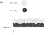
これはつまり、弾性保持されている第一の粒子部と圧粉体の部分である第二の粒子部とで、基材を構成するためそれぞれの役割を持っていることを意味する。これについては、図1を用いて説明する。図1において、接着剤によって基台11に固定されている粒子部(第一の粒子部)には、接着剤による空間がある。すなわち、第一の粒子部は、接着剤に粒子が分散した層構成をとることができる。一方、第一の粒子部の上の圧粉体を構成する粒子部は接着剤が存在することないため空間が少なく密度が高い粒子部(第二の粒子部)となっている。
This means that the first particle portion, which is elastically retained, and the second particle portion, which is part of the green compact, each have their own role in forming the base material. This will be explained using Figure 1. In Figure 1, the particle portion (first particle portion) that is fixed to the
固体電解質基材の作製方法の一つの例として、基台上から粒子部を押し込んで基材を作る方法があり、この場合第一の粒子部に対し第二の粒子部により押し込む力が加わる。また、押し込んで基材を作る方法に限られず、第二の粒子部の質量によっても第一の粒子部に対して押し込む力が加わる。
ここで、接着剤は例えば樹脂を含みうるが、硬化した状態であっても弾性変形可能である。そのため、第二の粒子部により伝えられる上記押し込む力によって、接着剤に固定された第一の粒子部がわずかにバネのように広がり、第一の粒子部は押し込む力に対して動くことができると考えられる。その結果、第一の粒子部が第二の粒子部を噛むように保持できる。そして、第一の粒子部と第二の粒子部との界面において、空間を少なくでき第二の粒子部を強く保持できると考えられる。同時に第二の粒子部は押し込む力により圧粉体の状態になり密度が高い固体電解質の粒子部となると考えられる。
As an example of a method for producing a solid electrolyte substrate, there is a method for producing a substrate by pressing a particle part from above a base, in which case a pressing force is applied by the second particle part to the first particle part. In addition, the method is not limited to a method for producing a substrate by pressing, and a pressing force is also applied by the mass of the second particle part to the first particle part.
Here, the adhesive may contain, for example, a resin, but is elastically deformable even in a cured state. Therefore, it is considered that the first particle part fixed to the adhesive spreads slightly like a spring due to the above-mentioned pushing force transmitted by the second particle part, and the first particle part can move against the pushing force. As a result, the first particle part can hold the second particle part as if biting it. It is considered that the space can be reduced at the interface between the first particle part and the second particle part, and the second particle part can be held firmly. At the same time, it is considered that the second particle part becomes a compressed powder state due to the pushing force, and becomes a particle part of a solid electrolyte with high density.
したがって、本開示における「弾性保持」とは、第一の粒子部が、接着剤に固定され、かつ、上述した第二の粒子部から伝えられる押し込む力によって第二の粒子部に含まれる
粒子を噛むように保持された状態をいう。
Therefore, in the present disclosure, "elastic retention" refers to a state in which the first particle portion is fixed to the adhesive and is held in such a way that it bites into the particles contained in the second particle portion by the pushing force transmitted from the second particle portion described above.
固体電解質基材において、第一の粒子部が「弾性保持」されていることは、例えば、後述するBIB-SEMによる測定において第一の粒子部が接着剤に由来する、例えば炭素C成分に固定されていること。さらにその上に第二の粒子部の圧粉体が形成されていることにより確認しうる。 In the solid electrolyte substrate, the "elastic retention" of the first particle portion can be confirmed, for example, by observing that the first particle portion is fixed to, for example, the carbon C component derived from the adhesive in measurements using a BIB-SEM described below, and further by the formation of a compressed powder body of the second particle portion on top of the first particle portion.
固体電解質基材において、第一の粒子部を「弾性保持」するためには、上述したように、基台に接着剤の層を形成し、該接着剤に分散して保持される第一の粒子部を形成する。そして、第一の粒子部に、固体電解質粒子の圧粉体を含む第二の粒子部を積層することが好ましい。すなわち、本開示の他の態様として、固体電解質基材は、基台と、該基台上の接着剤の層と、該接着剤に分散して保持された第一の粒子部と、該第一の粒子部に対して積層して保持された、固体電解質粒子の圧粉体を含む第二の粒子部と、を有する。 In order to "elastically retain" the first particle portion in the solid electrolyte substrate, as described above, a layer of adhesive is formed on the base, and the first particle portion is formed so as to be dispersed and retained in the adhesive. It is then preferable to laminate a second particle portion including a compact of solid electrolyte particles on the first particle portion. That is, as another aspect of the present disclosure, the solid electrolyte substrate has a base, a layer of adhesive on the base, a first particle portion dispersed and retained in the adhesive, and a second particle portion including a compact of solid electrolyte particles laminated and retained on the first particle portion.
また、固体電解質基材において、第二の粒子部が「圧粉体」になっていることは、後述するBIB-SEMによる断面観察において、面積割合、すなわち密度が高くなっていることで確認することができる。
好ましくは、走査型電子顕微鏡による固体電解質基材の断面観察において、第一の粒子部の面積割合(%)をd1とし、第二の粒子部の面積割合(%)をd2とする。d2が86%以上であることが好ましい。d2は、より好ましくは86~96%であり、さらに好ましくは87~94%である。
なお、d1は、好ましくは80~85%であり、より好ましくは82~85%である。
Furthermore, in the solid electrolyte base material, the fact that the second particle portion is a "compressed powder" can be confirmed by observing a cross section by a BIB-SEM described later, in which the area ratio, i.e., the density, is high.
Preferably, in a cross-sectional observation of the solid electrolyte substrate by a scanning electron microscope, the area ratio (%) of the first particle portion is d1, and the area ratio (%) of the second particle portion is d2. It is preferable that d2 is 86% or more. d2 is more preferably 86 to 96%, and further preferably 87 to 94%.
Incidentally, d1 is preferably 80 to 85%, and more preferably 82 to 85%.
また本開示の固体電解質基材であれば、第一の粒子部を弾性保持するために必要な接着剤は少量でよく、固体電解質層の作製時に、例えば基台を含む樹脂成分を除去する際には低温でよく、除去による密度低下影響を最低限にすることが可能にすることができる。 In addition, with the solid electrolyte substrate of the present disclosure, only a small amount of adhesive is required to maintain the elasticity of the first particle portion, and when producing the solid electrolyte layer, for example, the resin component including the base can be removed at a low temperature, making it possible to minimize the effect of density reduction due to removal.
以上のような固体電解質基材を作製するためには、基台に対して接着剤によって弾性保持される第一の粒子部と圧粉体を構成する第二の粒子部があることが重要であると考えられる。
このような構成とした固体電解質基材は、第一の粒子部及び第二の粒子部、特に第二の粒子部が高密度に充填されたものとなる。そのため、本開示の固体電解質基材を用いて固体電解質層を製造することにより、短絡が発生しにくくイオンが伝導しやすくなる。また、このような固体電解質層を用いた二次電池においては、内部抵抗が低下し、出力の向上ができる。
In order to produce the above-mentioned solid electrolyte substrate, it is considered important to have a first particle portion that is elastically held to the base by an adhesive and a second particle portion that constitutes a powder compact.
In the solid electrolyte substrate having such a configuration, the first particle portion and the second particle portion, especially the second particle portion, are densely packed. Therefore, by manufacturing a solid electrolyte layer using the solid electrolyte substrate of the present disclosure, short circuits are unlikely to occur and ions are easily conducted. Furthermore, in a secondary battery using such a solid electrolyte layer, the internal resistance is reduced and the output can be improved.
本開示では、固体電解質粒子を本開示の特徴を有して基台上に配された固体電解質基材を用いることで、前記形態を実現している。また固体電解質基材は、二次電池の材料として用いることができる。本開示においては、電子電導性及びイオン伝導性を、便宜的に「抵抗値」という指標を用いて評価する。 In the present disclosure, the above-mentioned form is realized by using a solid electrolyte substrate in which solid electrolyte particles are arranged on a base with the characteristics of the present disclosure. The solid electrolyte substrate can also be used as a material for secondary batteries. In the present disclosure, electronic conductivity and ionic conductivity are evaluated using an index called "resistance value" for convenience.
以下に、固体電解質基材、固体電解質層及びそれらを用いた二次電池、並びにその製造方法について詳述する。本開示の固体電解質基材は、固体電解質の製造に用いることができる。固体電解質は、二次電池の製造に用いることができる。以下、固体電解質粒子を用いた固体電解質基材を例に挙げて説明する。 The solid electrolyte substrate, the solid electrolyte layer, and the secondary battery using them, as well as the manufacturing method thereof, are described in detail below. The solid electrolyte substrate of the present disclosure can be used to manufacture a solid electrolyte. The solid electrolyte can be used to manufacture a secondary battery. The following description is given using an example of a solid electrolyte substrate using solid electrolyte particles.
基台は、基本的に固体電解質基材を構成するものであれば何でもよい。好ましくは、基台は樹脂を含む。樹脂などの有機材料で形成された基台を用いることで、後述する固体電解質層の製造工程において加熱による基台の除去を容易にすることができる。 The base may be any material that basically constitutes a solid electrolyte substrate. Preferably, the base contains a resin. By using a base formed of an organic material such as a resin, it is possible to easily remove the base by heating in the manufacturing process of the solid electrolyte layer described below.
基台の材料に含まれる樹脂としては、特に限定されないが、例えばポリエチレン(PE)、ポリプロピレン(PP)及びポリエチレンテレフタレート(PET)などのポリエステル、並びに、ナイロンなどのポリアミドなどを用いることができる。なかでも、分解温度や熱分解時に発生する気体の低有害性の観点から、基台はPETを含むことが好ましい。
基台の厚みは、好ましくは1~50μmであり、より好ましくは1~20μmであり、さらに好ましくは2~10μmである。
The resin contained in the material of the base is not particularly limited, and examples thereof include polyesters such as polyethylene (PE), polypropylene (PP) and polyethylene terephthalate (PET), and polyamides such as nylon. Among these, it is preferable that the base contains PET from the viewpoint of the decomposition temperature and the low harmfulness of the gas generated during thermal decomposition.
The thickness of the base is preferably 1 to 50 μm, more preferably 1 to 20 μm, and further preferably 2 to 10 μm.
接着剤は接着力、粘着力を備えた樹脂が好ましい。基台の表面の一部又は全体に接着剤が設けられていることが好ましい。接着剤によって、基台と第一の粒子部が弾性保持されることを目的としているため特に限定されないが、基台の表面に接着剤を塗布する方法などが好ましい。 The adhesive is preferably a resin with adhesive and tackiness. It is preferable that the adhesive is applied to a part or the entire surface of the base. Since the adhesive is intended to maintain the elasticity of the base and the first particle portion, there is no particular limitation, but a method of applying the adhesive to the surface of the base is preferable.
接着剤としては、特に限定されず、公知のものを用いることができる。接着剤は例えば樹脂を含む。接着剤は粘着性を有することが好ましい。粘着性とは、一時的な接着が可能な性質を示す。粘着性により、第一の粒子をより弾性保持しやすくなる。接着剤は、例えば、アクリル系粘着剤や、ゴム系粘着剤、シリコーン系粘着剤であってもよいし、熱や光などの外乱により粘着力が変化する熱可塑性樹脂や光硬化性樹脂などであってもよい。接着剤は粘着剤であることがより好ましい。接着剤は、アクリル系粘着剤や、ゴム系粘着剤、シリコーン系粘着剤からなる群から選択される少なくとも一であることがさらに好ましい。 The adhesive is not particularly limited, and any known adhesive can be used. The adhesive includes, for example, a resin. The adhesive preferably has adhesiveness. Adhesiveness refers to a property that allows temporary adhesion. Adhesiveness makes it easier to maintain the elasticity of the first particles. The adhesive may be, for example, an acrylic adhesive, a rubber adhesive, or a silicone adhesive, or may be a thermoplastic resin or a photocurable resin whose adhesive strength changes due to disturbances such as heat or light. It is more preferable that the adhesive is an adhesive. It is even more preferable that the adhesive is at least one selected from the group consisting of an acrylic adhesive, a rubber adhesive, and a silicone adhesive.
固体電解質基材は、例えば、基台と、粘着剤によって前記基台に保持された第一の粒子部と、前記第一の粒子部に対して積層して保持された、固体電解質粒子の圧粉体を含む第二の粒子部と、を有する。 The solid electrolyte substrate has, for example, a base, a first particle portion held on the base by an adhesive, and a second particle portion including a compact of solid electrolyte particles stacked and held on the first particle portion.
接着剤の厚み(硬化後の厚み)は特に制限されないが、好ましくは0.1~10μmであり、より好ましくは0.5~5μmであり、さらに好ましくは0.5~3μmである。 The thickness of the adhesive (thickness after curing) is not particularly limited, but is preferably 0.1 to 10 μm, more preferably 0.5 to 5 μm, and even more preferably 0.5 to 3 μm.
第一の粒子部に含まれる粒子は、特に限定されることないが、樹脂粒子及び固体電解質粒子からなる群から選択される少なくとも一の粒子であることが好ましい。
加熱によって消失する粒子である場合、後述する固体電解質層の製造工程において、容易に除去することができる。その際の粒子としては有機材料より形成でされているものがよく、特に限定されないが、第一の粒子部における粒子は樹脂粒子であってもよい。
The particles contained in the first particle portion are not particularly limited, but are preferably at least one particle selected from the group consisting of resin particles and solid electrolyte particles.
In the case where the particles are those that disappear by heating, they can be easily removed in the manufacturing process of the solid electrolyte layer described later. The particles in this case are preferably made of an organic material, and are not particularly limited, but the particles in the first particle portion may be resin particles.
樹脂粒子は、例えばポリエチレン(PE)、ポリプロピレン(PP)、ポリエチレンテレフタレート(PET)などのポリエステル、ポリアクリル樹脂、及びナイロンなどのポリアミドなどからなる群から選択される少なくとも一の樹脂の粒子を用いることができる。 The resin particles may be particles of at least one resin selected from the group consisting of polyesters such as polyethylene (PE), polypropylene (PP), and polyethylene terephthalate (PET), polyacrylic resins, and polyamides such as nylon.
また、第一の粒子部における粒子は、加熱によって消失せずに固体電解質層を形成する固体電解質粒子であってもよい。固体電解質粒子としては、特に限定されず、全固体電池に通常使用されるイオン伝導性固体を用いることができる。
固体電解質粒子は、例えば、Li-B酸化物系の固体電解質粒子、Li-Yb酸化物系の固体電解質粒子、ナシコン型の固体電解質粒子(LiAlTi(PO4)3、LiAlGe(PO4)3など)、Li-P-O系の固体電解質粒子(Li3PO4、LiPON(Li3PO4のOの一部をNで置換した粒子)など)からなる群から選択される少なくとも一の粒子が挙げられる。
The particles in the first particle portion may be solid electrolyte particles that do not disappear when heated and form a solid electrolyte layer. The solid electrolyte particles are not particularly limited, and any ion-conductive solid that is normally used in all-solid-state batteries may be used.
The solid electrolyte particles may be at least one particle selected from the group consisting of Li-B oxide-based solid electrolyte particles, Li-Yb oxide-based solid electrolyte particles, Nasicon-type solid electrolyte particles (LiAlTi(PO 4 ) 3 , LiAlGe(PO 4 ) 3 , etc.), and Li-P-O-based solid electrolyte particles (Li 3 PO 4 , LiPON (particles in which part of the O in Li 3 PO 4 is replaced with N), etc.).
好ましくは、固体電解質粒子は、酸化物系の固体電解質粒子を含む。上記固体電解質粒
子の中でも、Li-B酸化物系の固体電解質粒子、Li-Yb酸化物系の固体電解質粒子は、比較的低温(700℃以下)で焼結することができるため、一体型の電池の作製する際の焼結時の正極活物質粒子との反応を抑制し、イオン伝導性を保ちやすい。このため、固体電解質粒子は、Li-B酸化物系の固体電解質粒子、Li-Yb酸化物系の固体電解質粒子からなる群から選択される少なくとも一の粒子を含むことが好ましい。
Preferably, the solid electrolyte particles include oxide-based solid electrolyte particles. Among the above solid electrolyte particles, Li-B oxide-based solid electrolyte particles and Li-Yb oxide-based solid electrolyte particles can be sintered at a relatively low temperature (700° C. or less), and therefore, they are capable of suppressing the reaction with the positive electrode active material particles during sintering when preparing an integrated battery, and are therefore capable of easily maintaining ionic conductivity. For this reason, it is preferable that the solid electrolyte particles include at least one particle selected from the group consisting of Li-B oxide-based solid electrolyte particles and Li-Yb oxide-based solid electrolyte particles.
固体電解質粒子は、市販品を用いてもよく、材料として別途調製したものを用いてもよい。Li-B酸化物系の固体電解質粒子としては、例えばLi3BO3(株式会社豊島製作所製)や、Li3BO3のOの一部をCで置換した粒子などを用いることができる。また、Li-Yb酸化物系の固体電解質粒子としては、特開2022―130301に記載の化合物が挙げられ、例えばLi5.9Yb0.81La0.09Zr0.1(BO3)3などを用いることができる。これらの固体電解質粒子は事前に遊星ボールミル処理などにより非晶質化しておいてもよい。 The solid electrolyte particles may be commercially available or may be prepared separately as a material. Examples of the Li-B oxide solid electrolyte particles include Li 3 BO 3 (manufactured by Toshima Manufacturing Co., Ltd.) and particles in which part of O in Li 3 BO 3 is replaced with C. Examples of the Li-Yb oxide solid electrolyte particles include compounds described in JP-A-2022-130301, such as Li 5.9 Yb 0.81 La 0.09 Zr 0.1 (BO 3 ) 3. These solid electrolyte particles may be amorphous in advance by planetary ball milling or the like.
第二の粒子部における粒子は、固体電解質粒子を含む。固体電解質粒子としては、特に限定されず、全固体電池に通常使用されるイオン伝導性固体を用いることができる。上記に示す第一の粒子部に使用する固体電解質粒子を使用することができる。 The particles in the second particle portion include solid electrolyte particles. The solid electrolyte particles are not particularly limited, and any ion-conductive solid that is typically used in all-solid-state batteries can be used. The solid electrolyte particles used in the first particle portion described above can be used.
走査型電子顕微鏡による固体電解質基材の断面観察において、第一の粒子部の面積割合(%)の平均をd1とし、第二の粒子部の面積割合(%)の平均をd2としたとき、d1とd2とが異なることが好ましい。また、d1及びd2が、d1<d2を満たすことが好ましい。このようにd1とd2とが異なることで、加熱などによる樹脂の除去の際に接着剤より発生するガスが(好ましくは第一の粒子部を介して)抜けやすい。そのため、固体電解質に亀裂が入りにくく、短絡をより抑制しやすい。 In cross-sectional observation of the solid electrolyte substrate using a scanning electron microscope, when the average area ratio (%) of the first particle portion is d1 and the average area ratio (%) of the second particle portion is d2, it is preferable that d1 and d2 are different. It is also preferable that d1 and d2 satisfy d1<d2. By making d1 and d2 different in this way, gas generated from the adhesive when removing the resin by heating or the like is easily released (preferably via the first particle portion). Therefore, the solid electrolyte is less likely to crack, and short circuits are more easily suppressed.
第一の粒子部や第二の粒子部の面積割合は、Arによるブロードイオンビーム(BIB)で固体電解質基材の基台、第一の粒子部及び第二の粒子部の積層方向の断面を加工し、その断面を走査型電子顕微鏡法で得られる二次元像より求める。また電子線照射により発生する特性X線を検出し分光するEDX法にて接着剤の場所を測定することができる。 The area ratio of the first particle portion and the second particle portion is determined by processing the cross section of the base of the solid electrolyte substrate, the first particle portion, and the second particle portion in the stacking direction with a broad ion beam (BIB) of Ar, and obtaining a two-dimensional image of the cross section using a scanning electron microscope. The location of the adhesive can also be measured using the EDX method, which detects and disperses characteristic X-rays generated by electron beam irradiation.
本明細書において、第一の粒子部はSEM観察と共にEDX法による上記断面観察により接着剤によって保持されている粒子部のことを示している。第一の粒子部は、高さ(画像によるとY方向)方向に分布を持つが、接着剤によって保持されている粒子の最大高さまでの位置を第一の粒子部とする。よって、第二の粒子部はEDX法による上記断面観察により明らかに接着剤の無い部分となる。 In this specification, the first particle portion refers to the particle portion that is held by the adhesive as determined by the above cross-sectional observation using the EDX method together with SEM observation. The first particle portion has a distribution in the height direction (Y direction in the image), but the position up to the maximum height of the particle held by the adhesive is defined as the first particle portion. Therefore, the second particle portion is clearly a portion without adhesive as determined by the above cross-sectional observation using the EDX method.
d1及びd2の差分(好ましくはd2-d1)は、統計的に有意な差があることが好ましい。d1及びd2の差分(好ましくはd2-d1)は、2%以上が好ましい。そうすることにより、第一の粒子部は接着剤により弾性保持されやすく、第二の粒子部は第一の粒子部によってより固定されやすい。その結果、固体電解質粒子である第二の粒子部を十分に高密度で形成することができるため、イオン伝導性をより向上することができる。 The difference between d1 and d2 (preferably d2-d1) is preferably statistically significant. The difference between d1 and d2 (preferably d2-d1) is preferably 2% or more. By doing so, the first particle portion is more likely to be elastically maintained by the adhesive, and the second particle portion is more likely to be fixed by the first particle portion. As a result, the second particle portion, which is a solid electrolyte particle, can be formed with a sufficiently high density, thereby further improving ionic conductivity.
d1及びd2の差分(好ましくはd2-d1)は、好ましくは2~10%であり、より好ましくは3~7%である。
d1及びd2の差分は、接着剤の厚みを増やすことにより大きくすることができる。また、d1及びd2の差分は、接着剤の厚みを薄くすることや、接着剤の圧力に対する変化量を小さくすることにより小さくすることができる。
The difference between d1 and d2 (preferably d2-d1) is preferably 2 to 10%, more preferably 3 to 7%.
The difference between d1 and d2 can be increased by increasing the thickness of the adhesive, and can be decreased by decreasing the thickness of the adhesive or decreasing the amount of change in the adhesive relative to pressure.
第一の粒子部の厚みは、好ましくは1~20μmであり、より好ましくは2~15μmであり、さらに好ましくは3~10μmである。
また、第二の粒子部の厚みは、好ましくは10μm以上100μm未満であり、より好ましくは20~90μmであり、さらに好ましくは25~80μmである。
第一の粒子部及び第二の粒子部の合計の厚みは、100μm未満であることが好ましい。上記範囲であることで、焼結後の固体電解質の抵抗を小さくすることができる。第一の粒子部及び第二の粒子部の合計の厚みは、好ましくは20μm以上100μm未満であり、より好ましくは25~90μmであり、さらに好ましくは30~80μmである。
The thickness of the first particle portion is preferably 1 to 20 μm, more preferably 2 to 15 μm, and further preferably 3 to 10 μm.
The thickness of the second particle portion is preferably 10 μm or more and less than 100 μm, more preferably 20 to 90 μm, and further preferably 25 to 80 μm.
The total thickness of the first particle portion and the second particle portion is preferably less than 100 μm. By being in the above range, the resistance of the solid electrolyte after sintering can be reduced. The total thickness of the first particle portion and the second particle portion is preferably 20 μm or more and less than 100 μm, more preferably 25 to 90 μm, and even more preferably 30 to 80 μm.
固体電解質基材における、接着剤の厚み、第一の粒子部の厚み、第二の粒子部の厚みは、BIB-SEMによる観察にて測定することができる。任意の10点の算術平均値を採用する。 The thickness of the adhesive, the thickness of the first particle portion, and the thickness of the second particle portion in the solid electrolyte substrate can be measured by observation with a BIB-SEM. The arithmetic average value of 10 arbitrary points is used.
<固体電解質基材の製造方法1>
以下、図2を参照して、固体電解質基材の製造方法の一例を詳細に説明する。以下、第一の粒子部と第二の粒子部に固体電解質粒子を用いた固体電解質基材を例に挙げて説明するが、第一の粒子部に樹脂粒子を用いても同様に製造することができる。
<Method of manufacturing
An example of a method for producing a solid electrolyte substrate will be described in detail below with reference to Fig. 2. A solid electrolyte substrate using solid electrolyte particles for the first particle portion and the second particle portion will be described below as an example, but the substrate can be produced in the same manner when resin particles are used for the first particle portion.
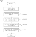
基台、接着剤、第一の粒子部及び第二の粒子部がこの順に積層された固体電解質基材の製造方法は、下記の(1)~(5)の工程を有することが好ましい。
(1)接着剤を備えた基台を準備する準備工程。
(2)接着剤の表面に第一の粒子を配置する第1工程(図2中、S101)。
(3)第一の粒子に対して圧力をかけ第一の粒子部を作製する第2工程(図中、S102)
(4)第一の粒子部の表面に第二の粒子を配置する第3工程(図中、S103)。
(5)第二の粒子に対して圧力をかけ第二の粒子部を作製し固体電解質基材を得る第4工程(図中、S104)
A method for producing a solid electrolyte substrate in which a base, an adhesive, a first particle portion, and a second particle portion are laminated in this order preferably includes the following steps (1) to (5).
(1) A preparation step of preparing a base with an adhesive.
(2) A first step of disposing first particles on the surface of the adhesive (S101 in FIG. 2).
(3) A second step of applying pressure to the first particles to produce a first particle portion (S102 in the figure).
(4) A third step (S103 in the drawing) of arranging second particles on the surfaces of the first particle portion.
(5) A fourth step (S104 in the figure) of applying pressure to the second particles to produce second particle portions and obtain a solid electrolyte substrate.
(準備工程)
準備工程として、接着剤を備えた基台を準備する。なお、本開示において、「接着剤を備えた」とは、基台の表面の一部又は全体に接着剤が設けられていることを示す。
基台としては、上述の基台を用いることができる。接着剤を設ける方法は特に限定されないが、基台の表面に接着剤を塗布する方法などが好ましい。
(Preparation process)
In the preparation step, a base provided with an adhesive is prepared. In the present disclosure, the term "provided with an adhesive" refers to an adhesive being provided on a part or the entire surface of the base.
The base may be any of the bases described above. The method for providing the adhesive is not particularly limited, but a method of coating the surface of the base with adhesive is preferred.
接着剤としては、特に限定されず、公知のものを用いることができる。例えば、アクリル系粘着剤や、ゴム系粘着剤、シリコーン系粘着剤であってもよいし、熱や光などの外乱により粘着力が変化する熱可塑性樹脂や光硬化性樹脂などであってもよい。接着剤は上述した通りであり、粘着剤が好ましい。粘着性を有する接着剤により弾性保持させやすい。 The adhesive is not particularly limited, and any known adhesive can be used. For example, it may be an acrylic adhesive, a rubber adhesive, or a silicone adhesive, or it may be a thermoplastic resin or a photocurable resin whose adhesive strength changes in response to disturbances such as heat or light. The adhesive is as described above, and an adhesive is preferred. An adhesive with tackiness makes it easier to maintain elasticity.
(第1工程及び第2工程、第3工程、第4工程)
第1工程は、基台上の接着剤の表面に第一の粒子を配置する工程である。接着剤の露出がないように粒子を配置することが好ましい。第一の粒子の厚みは、好ましくは1~20μmであり、より好ましくは2~15μmであり、さらに好ましくは3~10μmである。
(
The first step is to arrange the first particles on the surface of the adhesive on the base. It is preferable to arrange the particles so that the adhesive is not exposed. The thickness of the first particles is preferably 1 to 20 μm, more preferably 2 to 15 μm, and even more preferably 3 to 10 μm.
第2工程は、第一の粒子を接着剤によって、弾性保持されるように固定させる工程である。圧力は特に制限されず、第一の粒子を弾性保持可能な程度であればよい。ある程度の力であれば容易に保持させることができる。圧力は、好ましくは5~300kPaであり、より好ましくは100~300kPaである。 The second step is to fix the first particles with an adhesive so that they are elastically retained. There are no particular restrictions on the pressure, and it is sufficient if the pressure is sufficient to retain the elasticity of the first particles. A certain degree of force can easily retain the particles. The pressure is preferably 5 to 300 kPa, and more preferably 100 to 300 kPa.
第3工程は、第一の粒子部の上に第二の粒子を配置する工程である。第二の粒子は、圧粉体を形成可能な程度に配置すればよい。第二の粒子の厚みは、好ましくは10μm以上
100μm未満であり、より好ましくは20~90μmであり、さらに好ましくは25~80μmである。
The third step is a step of disposing the second particles on the first particle portion. The second particles may be disposed to such an extent that a powder compact can be formed. The thickness of the second particles is preferably 10 μm or more and less than 100 μm, more preferably 20 to 90 μm, and even more preferably 25 to 80 μm.
そして、第4工程は第2工程と同様に圧力をかけることにより、第一の粒子部に対して第二の粒子部を積層して保持させ、第二の粒子部からなる圧粉体を作製する工程である。圧粉体となる程度に圧力を加えればよく。第4工程での圧力も特に制限されないが、好ましくは5~300kPaであり、より好ましくは100~300kPaである。 The fourth step is a step in which pressure is applied in the same manner as in the second step to stack and hold the second particle portion against the first particle portion, thereby producing a green compact made of the second particle portion. It is sufficient to apply pressure to the extent that a green compact is formed. There are no particular limitations on the pressure in the fourth step, but it is preferably 5 to 300 kPa, and more preferably 100 to 300 kPa.
<電解質基材の製造方法2>
第一の粒子と第二の粒子を同じ固体電解質粒子を使用する場合は、接着剤部の表面に固体電解質粒子を配置する第1工程の後、第2工程、第3工程がなく、第4の工程を行えばよい。これにより、固体電解質粒子の一部が接着剤によって基台に弾性保持されて第一の粒子部が形成され、さらに第一の粒子部に積層して保持された圧粉体を含む第二の粒子部を形成することができる。
<Method of manufacturing
When the same solid electrolyte particles are used for the first particles and the second particles, after the first step of disposing the solid electrolyte particles on the surface of the adhesive part, the second and third steps are not required, and only the fourth step may be performed. This allows a first particle part to be formed by elastically holding a part of the solid electrolyte particles to the base by the adhesive, and further allows a second particle part to be formed that includes a powder compact stacked and held on the first particle part.
すなわち、基台、接着剤、及び固体電解質粒子がこの順に積層された固体電解質基材の製造方法2は、下記の(1)~(3)の工程を有してもよい。
(1)接着剤を備えた基台を準備する準備工程。
(2)接着剤の表面に固体電解質粒子を配置する工程。
(3)固体電解質粒子に対して圧力をかけ、固体電解質粒子の粒子部を作製し固体電解質基材を得る工程。
That is, the method for producing a
(1) A preparation step of preparing a base with an adhesive.
(2) disposing solid electrolyte particles on the surface of the adhesive;
(3) A step of applying pressure to the solid electrolyte particles to produce particle portions of the solid electrolyte particles and obtain a solid electrolyte substrate.
また、基台、接着剤、及び固体電解質粒子がこの順に積層された固体電解質基材の製造方法2は、下記の(1)~(3)の工程を有することが好ましい。
(1)接着剤を備えた基台を準備する準備工程。
(2)接着剤の表面に固体電解質粒子を配置する工程。
(3)固体電解質粒子に対して圧力をかけ、接着剤に保持された第一の粒子部及び固体電解質粒子の圧粉体を含む第二の粒子部を作製し固体電解質基材を得る工程。
Moreover, the method for producing a
(1) A preparation step of preparing a base with an adhesive.
(2) disposing solid electrolyte particles on the surface of the adhesive;
(3) A step of applying pressure to the solid electrolyte particles to produce a first particle portion held by the adhesive and a second particle portion including a compact of the solid electrolyte particles, thereby obtaining a solid electrolyte substrate.
固体電解質粒子の厚みは、好ましくは10μm以上100μm未満であり、より好ましくは20~90μmであり、さらに好ましくは25~80μmである。(3)の工程での圧力は、好ましくは5~300kPaであり、より好ましくは100~300kPaである。 The thickness of the solid electrolyte particles is preferably 10 μm or more and less than 100 μm, more preferably 20 to 90 μm, and even more preferably 25 to 80 μm. The pressure in step (3) is preferably 5 to 300 kPa, and more preferably 100 to 300 kPa.
第一の粒子の粒径は、特に限定されないが、例えば、一次粒子の体積基準の粒度分布における累積10%粒径(r10)が、0.1~10.0μmであることが好ましく、1.0~7.0μmであることがより好ましい。また、一次粒子の体積基準の粒度分布における累積50%粒径(r50)が、0.5~20.0μmであることが好ましく、2.0~10.0μmであることがより好ましい。さらに、一次粒子の体積基準の粒度分布における累積90%粒径(r90)が、2.0~20.0μmであることが好ましく、3.0~15.0μmであることがより好ましい。 The particle size of the first particles is not particularly limited, but for example, the cumulative 10% particle size (r10) in the volumetric particle size distribution of the primary particles is preferably 0.1 to 10.0 μm, and more preferably 1.0 to 7.0 μm. The cumulative 50% particle size (r50) in the volumetric particle size distribution of the primary particles is preferably 0.5 to 20.0 μm, and more preferably 2.0 to 10.0 μm. Furthermore, the cumulative 90% particle size (r90) in the volumetric particle size distribution of the primary particles is preferably 2.0 to 20.0 μm, and more preferably 3.0 to 15.0 μm.
第二の粒子は固体電解質粒子である。例えば、上述の固体電解質粒子を第二の粒子として用いることができる。 The second particles are solid electrolyte particles. For example, the above-mentioned solid electrolyte particles can be used as the second particles.
第二の粒子の一次粒子の粒径は、特に限定されない。例えば、第二の粒子は、一次粒子の体積基準の粒度分布における累積10%粒径(r10)が、0.1~10.0μmであることが好ましく、1.0~7.0μmであることがより好ましい。また、一次粒子の体積基準の粒度分布における累積50%粒径(r50)が、0.5~20.0μmであることが好ましく、2.0~10.0μmであることがより好ましい。また、一次粒子の体積
基準の粒度分布における累積90%粒径(r90)が、2.0~20.0μmであることが好ましく、3.0~15.0μmであることがより好ましい。
第一の粒径と、第二の粒径の比は、特に限定されない。
The particle size of the primary particles of the second particles is not particularly limited. For example, the cumulative 10% particle size (r10) in the volume-based particle size distribution of the primary particles of the second particles is preferably 0.1 to 10.0 μm, more preferably 1.0 to 7.0 μm. Furthermore, the cumulative 50% particle size (r50) in the volume-based particle size distribution of the primary particles is preferably 0.5 to 20.0 μm, more preferably 2.0 to 10.0 μm. Furthermore, the cumulative 90% particle size (r90) in the volume-based particle size distribution of the primary particles is preferably 2.0 to 20.0 μm, more preferably 3.0 to 15.0 μm.
The ratio of the first particle size to the second particle size is not particularly limited.
[固体電解質基材製造装置1]
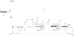
図3は、固体電解質基材製造装置1の構成を模式的に示す図である。固体電解質基材製造装置1は、基台11に第一の粒子部14及び第二の粒子部12を形成する装置である。固体電解質基材製造装置1は、基台11を格納供給する格納容器21と、基台11を搬送するベルト装置22と、を有する。また、固体電解質基材製造装置1は、基台11に接着剤を設けるための液体を配置する液体付与装置201を有している。ベルト装置には、上流側より液体塗布装置201についで、第一の粒子を積層する第一の粒子付与装置202、粒子固定装置25が設けられている。そして、その下流に第二の粒子を積層する第二の粒子付与装置203、粒子固定装置26が設けられている。
[Solid electrolyte base material manufacturing device 1]
3 is a diagram showing a schematic configuration of the solid electrolyte
液体付与装置201としては、インクジェット方式で液体を吐出する装置や液体を塗布する装置を用いることができるが、フレキソ版などの有版方法を用いることもできる。なかでも、液体付与装置としては、インクジェット方式で液体を吐出する装置を用いることが好ましい。
As the
インクジェット方式で液体を吐出する装置は、例えば、サーマルタイプ、ピエゾタイプ、静電タイプ、コンティニュアスタイプなど、さまざまな吐出方法の装置を用いることができる。 Devices that eject liquid using the inkjet method can use devices with a variety of ejection methods, such as thermal type, piezoelectric type, electrostatic type, and continuous type.
液体付与装置201が付与する接着剤を設けるための液体としては、第一の粒子部を形成しうる第一の粒子を保持できる材料を含むものであれば、水性であっても油性であってもよい。第一の粒子と反応しない材料を選択するなど適宜選択される。また、液体付与装置201は、複数種の液体によってパターンを形成してもよい。例えば、液体付与装置201は、基材11で反応させて粘着性を高めるような2種の液体を付与してもよい。第一の粒子を付着できる材料としては、アクリル樹脂などの樹脂が挙げられる。
The liquid applied by the
第一の粒子付与装置202は、接着剤が積層された基台11に、第一の粒子を含む粉末を配置する。これにより、基台11上の材料によって第一の粒子が固定される。
The first
第一の粒子付与装置202による粉末の付与手段は、粉末を基台11に向けて吹き付ける手段や、振りかける手段を用いることができる。第一の粒子付与装置202は、基台11に固定されなかった第一の粒子を、振動、遠心や送風、吸引などの手段で除去する手段をさらに備えていてもよい。
The powder application means of the first
粒子固定装置25は、加圧ローラ223c及び223dを有し、加圧ローラ223dは従動で回転している。加圧ローラ223c、223dの少なくとも一方は、表層に弾性層を有するソフトローラを用いることが好ましく、例えば、ステンレス製の芯金の表面にシリコーンゴムやフッ素ゴムの弾性層を設けたソフトローラを用いることができる。また、加圧ローラ223c、223dの少なくとも一方の内部には、不図示の加熱ヒーターが内蔵されていてもよい。
The
基台11は、ベルト装置により加圧ローラ223c、223d間の加圧部に搬送される。基材11が加圧ローラ223c、223dにより加圧されると、基台上の接着剤の表面に配置された第一の粒子は基台上の接着剤に保持され第一の粒子部が形成される。このとき、上述した加熱ヒーターにより、基台上の接着剤の粒子を再配置しやすくしても構わない。また、基材上の接着剤を加熱するために、粒子固定装置25の上流部に加熱源を設け
ても構わない。加圧ローラによる圧力は上述した範囲が好ましい。
The
第一の粒子部14が乗っている基台11は、ベルト装置により第二の粒子付与装置203まで搬送される。第二の粒子付与装置203は、第一の粒子部14がある基台11に、第二の粒子を含む粉末を配置する。
The base 11 on which the
次に第二の粒子が付与された基台11は、ベルト装置22により加圧ローラ224c、224d間の加圧部に搬送される。粒子固定装置26は、粒子固定装置25同様、加圧ローラ224c及び224dを有し、加圧ローラ224dは従動で回転している。基材11が加圧ローラ224c、224dにより加圧されると、基台上の第一の粒子部14の上に第二の粒子により第二の粒子部12が形成される。
Next, the base 11 to which the second particles have been applied is transported by the
固体電解質基材製造装置1は、液体付与装置201によって付与された液体の少なくとも一部を蒸発させて、基台11上の材料の量や厚さなどを制御する乾燥装置をさらに有していてもよい。この乾燥装置は、液体付与装置201の下流側に設ければよい。乾燥後基台上の材料は、液体、固形分を含む液体又は固形分のみでも構わない。
The solid electrolyte
加圧ローラ223c、加圧ローラ224cは、基台上の粒子と接触するため、粒子の付着を抑制するために、表面をフッ素等の離型性の良い材料でコーティングするのが好ましい。また、加圧ローラ223c、加圧ローラ224cに付着した粒子を除去するクリーニング機構を設けても構わない。また粒子層を保護材(不図示)で被覆した状態で加圧するのがさらに好ましい。
Since the
このとき、使用する保護材は、離型性の良い材料が好ましく、樹脂であればフッ素シート、金属であればニクロム箔などが好ましい。保護材を用いる場合は、粒子固定装置25の下流、且つ第二の粒子付与装置203の上流側に保護材を除去する除去機構(不図示)を設ける。
In this case, the protective material used is preferably a material with good releasability, and if it is resin, a fluorine sheet is preferable, and if it is metal, nichrome foil is preferable. When using a protective material, a removal mechanism (not shown) for removing the protective material is provided downstream of the
[固体電解質基材製造装置2]
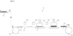
図4は、固体電解質基材製造装置2の構成を模式的に示す図である。固体電解質基材製造装置2は、固体電解質基材製造装置1と同じく基台11に固体電解質層12を形成する装置であって、基台11を格納供給する格納容器21と、基台11を搬送するベルト装置22と、を有する。また、固体電解質基材製造装置2は、基台11に接着部を設けるための液体を配置する液体付与装置201を有している。ベルト装置には、上流側より液体塗布装置201についで、第一の粒子付与装置202、粒子固定装置301、その下流に第2の粒子付与装置203、粒子固定装置302が設けられている。
[Solid electrolyte base material manufacturing device 2]
4 is a diagram showing a schematic configuration of the solid electrolyte
粒子固定をする工程がプレスによって固定することが固体電解質基材製造装置1とは異なっており、その他の構成は同様である。またプレスする際の圧力も上述した範囲が好ましい。圧力は、5kPa以上が好ましく、また基台の強度に依るがPETフィルムを使用する際は破損しないよう300kPa以下が好ましい。より好ましくは100~300kPaである。
The process of fixing the particles is different from that of the solid electrolyte
[そのほかの固体電解質基材製造装置]
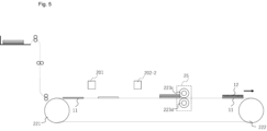
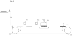
図5、図6では、第一の粒子と第二の粒子とで同じものを使用する際の固体電解質基材製造装置を模した図である。それぞれ、同じ粒子を使用するため、粒子付与装置202-2は一つでよい。また図5では加圧ローラで粒子固定し、図6ではプレスによる粒子固定を行う。
[Other solid electrolyte substrate manufacturing equipment]
5 and 6 are diagrams illustrating a solid electrolyte substrate manufacturing apparatus when the same particles are used for the first particles and the second particles. Since the same particles are used for both, only one particle applying device 202-2 is required. In addition, in FIG. 5, the particles are fixed by a pressure roller, and in FIG. 6, the particles are fixed by a press.
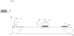
また図7、図8では元々基台に接着剤が塗布されているものを利用した固体電解質基材
製造装置である。基台11に接着剤が事前に塗布されているため、基台には保護フィルムが貼ってある。保護フィルム除去機構401にて保護フィルムを取り除き次工程へと移る。
7 and 8 show a solid electrolyte substrate manufacturing apparatus that utilizes a base that is originally coated with adhesive. Since adhesive is applied to the base 11 in advance, a protective film is attached to the base. The protective film is removed by a protective film removing mechanism 401, and the apparatus moves to the next process.
固体電解質基材において、固体電解質粒子による基台表面のカバー率は、60面積%以上であることが好ましく、70面積%以上であることがより好ましく、80面積%以上であることがさらに好ましい。 In the solid electrolyte substrate, the coverage of the base surface by the solid electrolyte particles is preferably 60 area% or more, more preferably 70 area% or more, and even more preferably 80 area% or more.
本開示において、基台表面のカバー率とは、基台表面の全体の面積に対する、固体電解質粒子により被覆された面積の割合(面積%)を示す。固体電解質粒子による基台表面のカバー率は、粒子層が形成されている領域を基材鉛直方向から光学顕微鏡により撮影し、固体電解質粒子により被覆されている領域の面積の割合を画像処理ソフトによって算出することで測定できる。測定方法の詳細は後述する。 In this disclosure, the coverage rate of the base surface refers to the ratio (area %) of the area covered by solid electrolyte particles to the total area of the base surface. The coverage rate of the base surface by solid electrolyte particles can be measured by photographing the area where the particle layer is formed using an optical microscope from the direction perpendicular to the substrate, and calculating the area ratio of the area covered by solid electrolyte particles using image processing software. The measurement method will be described in detail later.
カバー率の上限は特に限定されないが、99面積%以下であることが好ましく、98面積%以下であることがより好ましい。例えば、固体電解質粒子による樹脂基材表面のカバー率は、好ましくは60~99面積%、70~99面積%、80~99面積%。60~98面積%、70~98面積%、80~98面積%の範囲である。
カバー率が上記範囲であることで、基台上に緻密な粒子層が形成され、固体電解質層内の粒子の緻密性を向上できる。その結果、イオン伝導性をより向上できる。
The upper limit of the coverage is not particularly limited, but is preferably 99% by area or less, and more preferably 98% by area or less. For example, the coverage of the resin substrate surface by the solid electrolyte particles is preferably in the range of 60 to 99% by area, 70 to 99% by area, 80 to 99% by area, 60 to 98% by area, 70 to 98% by area, or 80 to 98% by area.
When the coverage is within the above range, a dense particle layer is formed on the base, and the denseness of the particles in the solid electrolyte layer can be improved, leading to further improved ion conductivity.
<固体電解質層の製造方法>
以下、図9を参照して、固体電解質層の製造方法の一例を詳細に説明する。
固体電解質層の製造方法は、下記の2つの工程(A工程、B工程)を有する。
(A工程)固体電解質基材より、基台を除去し固体電解質一体物を成形するA工程
(B工程)固体電解質一体物を焼結させ固体電解質層を得るB工程
すなわち、基台を除去し、一体物を得る工程と一体物を焼結方法により製造された固体電解質層を固体電解質として用いることができる。
以下、固体電解質層の製造方法の各工程について詳細を説明する。
<Method of Manufacturing Solid Electrolyte Layer>
Hereinafter, an example of a method for manufacturing a solid electrolyte layer will be described in detail with reference to FIG.
The method for producing the solid electrolyte layer includes the following two steps (step A and step B).
(Step A) Step A is to remove the base from the solid electrolyte substrate to form a solid electrolyte integrated body. (Step B) Step B is to sinter the solid electrolyte integrated body to obtain a solid electrolyte layer. In other words, the solid electrolyte layer produced by the step of removing the base to obtain an integrated body and the sintering method of the integrated body can be used as a solid electrolyte.
Each step of the method for producing the solid electrolyte layer will be described in detail below.
(固体電解質層の製造方法-A工程)
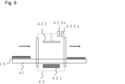
A工程は、固体電解質基材より固体電解質一体物を成形する工程であり、基台を除去する工程である。なお、第1の粒子部に樹脂粒子を用いた場合は当該樹脂粒子の樹脂成分や、接着剤の樹脂成分も基台とともに除去されることが好ましい。そのため、ここで除去する基台とは、基台も含めた樹脂成分である。基台は加熱により除去することが好ましい。図9は、焼結処理装置の構成を模式的に示す図である。焼結処理装置は、固体電解質基材15を搬送する搬送装置41と、積層体15を加熱する加熱炉42と、を有する。
A工程の前に、固体電解質基材を複数積層してもよい。積層数は、特に限定されず、所望の固体電解質の容量に応じて決定すればよい。
(Method for producing solid electrolyte layer - Step A)
Step A is a step of forming a solid electrolyte integral from a solid electrolyte substrate, and is a step of removing the base. When resin particles are used for the first particle portion, it is preferable that the resin components of the resin particles and the resin components of the adhesive are also removed together with the base. Therefore, the base to be removed here is the resin components including the base. It is preferable to remove the base by heating. FIG. 9 is a diagram showing a schematic configuration of a sintering treatment device. The sintering treatment device has a conveying device 41 that conveys the
A plurality of solid electrolyte substrates may be laminated before step A. The number of layers is not particularly limited and may be determined according to the desired capacity of the solid electrolyte.
搬送装置41は、作製された固体電解質基材15を受け取って加熱炉42へと搬送する。搬送装置41は、固体電解質基材15を搬送可能な装置であることが好ましい。固体電解質基材15を搬送可能な装置として、例えば、ベルトコンベア、ローラ、ロボットアームなどが挙げられる。
The conveying device 41 receives the produced
加熱炉42は、固体電解質基材15を加熱する炉である。加熱炉42は、加熱手段421と、加圧手段422と、雰囲気調整手段423と、を有する。加熱炉42としては、セラミックなどの焼成に用いられる焼成炉を用いることができる。加圧手段422は、加熱炉42において加熱されている積層体15を加圧したり、加熱前後の積層体15を加圧したりする。
The heating furnace 42 is a furnace that heats the
なお、加圧手段422は、積層体15を加圧する加圧部が気体を通過させやすい多孔質体で形成されていることが好ましい。雰囲気調整手段423は、雰囲気ガス供給手段423a及び減圧手段423bを有し、加熱炉42の処理空間内の雰囲気ガスの調整を行う。
雰囲気ガスとしては、酸化雰囲気(O2)、不活性雰囲気(Ar、N2等)や還元雰囲気(Ar-H2)を用いることができるが、大気下で焼結を行ってもよい。
In addition, it is preferable that the pressurizing means 422 has a pressurizing portion for pressurizing the laminate 15 formed of a porous material that allows easy passage of gas. The atmosphere adjusting means 423 has an atmosphere gas supplying means 423a and a pressure reducing means 423b, and adjusts the atmosphere gas in the processing space of the heating furnace 42.
The atmospheric gas that can be used includes an oxidizing atmosphere (O 2 ), an inert atmosphere (Ar, N 2 , etc.) and a reducing atmosphere (Ar-H 2 ), but sintering may be performed in air.
焼結処理する際に、固体電解質基材中の基台11の熱分解温度以上の温度で加熱することが好ましく、固体電解質基材中の各粒子層の熱分解温度未満の温度で加熱することが好ましい。固体電解質基材を加熱する温度としては、200℃以上1000℃以下であることが好ましく、400℃以上800℃以下であることがさらに好ましい。焼結温度にて30分以上維持することが好ましく、1時間以上維持することがより好ましい。基台を除去可能な時間加熱すればよく、上限は特に制限されないが、好ましくは3時間以下、より好ましくは2時間以下である。 During the sintering process, it is preferable to heat at a temperature equal to or higher than the thermal decomposition temperature of the base 11 in the solid electrolyte substrate, and it is preferable to heat at a temperature lower than the thermal decomposition temperature of each particle layer in the solid electrolyte substrate. The temperature to which the solid electrolyte substrate is heated is preferably 200°C or higher and 1000°C or lower, and more preferably 400°C or higher and 800°C or lower. It is preferable to maintain the sintering temperature for 30 minutes or more, and more preferably 1 hour or more. It is sufficient to heat for a period of time that allows the base to be removed, and although there is no particular upper limit, it is preferably 3 hours or less, and more preferably 2 hours or less.
熱分解温度とは、焼結処理装置における加熱の際の雰囲気下で温度を徐々に上げていった場合に、その材料の重量減少が始まる温度のことである。したがって、基台の熱分解温度以上の温度で固体電解質基材を加熱することで、固体電解質基材の基台を分解して除去することができる。 The thermal decomposition temperature is the temperature at which the weight of the material begins to decrease when the temperature is gradually increased in the heating atmosphere in the sintering processing device. Therefore, by heating the solid electrolyte substrate at a temperature equal to or higher than the thermal decomposition temperature of the substrate, the substrate of the solid electrolyte substrate can be decomposed and removed.
加熱温度は、基台の熱分解温度以上の温度であることが好ましいが、熱分解温度よりもさらに高い温度で加熱することが好ましい。具体的には、焼結処理装置における加熱の際の雰囲気(典型的には空気)下で室温(25℃)から5℃/分の割合で昇温させて熱重量分析を行った場合に、初期質量の70質量%となるときの温度以上の温度で加熱することが好ましい。具体的には、例えば385℃以上であることが好ましい。 The heating temperature is preferably equal to or higher than the thermal decomposition temperature of the base, but it is preferable to heat at a temperature even higher than the thermal decomposition temperature. Specifically, when the temperature is increased from room temperature (25°C) at a rate of 5°C/min in the atmosphere (typically air) during heating in the sintering treatment device and thermogravimetric analysis is performed, it is preferable to heat at a temperature equal to or higher than the temperature at which the mass becomes 70% of the initial mass. Specifically, for example, 385°C or higher is preferable.
また、同様に熱重量分析を行ったときに、初期質量の50質量%となるときの温度以上の温度で加熱することがより好ましく、初期質量量の20質量%となるときの温度以上の温度で加熱することがさらに好ましい。具体的には、例えば400℃以上であることが好ましく、450℃以上であることがより好ましい。これにより、基台の除去に要する時間を短縮したり、基台の除去率を高めたりすることができる。
このように、焼結処理装置が加熱により基台を除去する場合には、固体電解質粒子が、基台よりも高い熱分解温度を有することが好ましい。
Similarly, when a thermogravimetric analysis is performed, it is more preferable to heat the material at a temperature equal to or higher than the temperature at which the mass is reduced to 50% by mass of the initial mass, and it is even more preferable to heat the material at a temperature equal to or higher than the temperature at which the mass is reduced to 20% by mass of the initial mass. Specifically, for example, the temperature is preferably 400° C. or higher, and more preferably 450° C. or higher. This makes it possible to shorten the time required to remove the base and to increase the removal rate of the base.
In this way, when the sintering apparatus removes the base by heating, it is preferable that the solid electrolyte particles have a higher thermal decomposition temperature than the base.
固体電解質基材を複数積層する場合、焼結処理装置は、加熱により、固体電解質基材中の基台の少なくとも一部を除去し、積層した上下の固体電解質の層の粒子が接触する部分を設けることが好ましい。したがって、固体電解質基材15中の基台は90質量%以上を消失させることが好ましく、95質量%以上を消失させることがより好ましく、97質量%以上を消失させることがさらに好ましい。その際、基台は燃焼又はガス化して気体として外部に放出されることが好ましい。このとき、熱分解によってガス化した気体は装置の外部に放出することが好ましい。
When multiple solid electrolyte substrates are stacked, the sintering apparatus preferably removes at least a portion of the base in the solid electrolyte substrate by heating to provide a portion where the particles of the upper and lower stacked solid electrolyte layers come into contact. Therefore, it is preferable to eliminate 90% by mass or more of the base in the
焼結処理装置は、減圧手段423bによって、放出された気体を加熱炉42の外部に排気することが好ましい。雰囲気ガス供給手段423aなどによって、加熱炉42の内部を酸化雰囲気、すなわち、空気などの酸素ガスを含む雰囲気としておくことで、基台を燃焼させて除去することができる。一方、固体電解質粒子によっては、酸化雰囲気での焼結により分解や組成変化を引き起こす場合がある。このような場合には、不活性雰囲気(Ar、N2等)や還元雰囲気(Ar-H2)で焼結することが好ましい。 The sintering apparatus preferably exhausts the released gas to the outside of the heating furnace 42 by the pressure reducing means 423b. The inside of the heating furnace 42 is kept in an oxidizing atmosphere, i.e., an atmosphere containing oxygen gas such as air, by the atmospheric gas supplying means 423a or the like, so that the base can be burned and removed. On the other hand, depending on the solid electrolyte particles, decomposition or composition change may occur due to sintering in an oxidizing atmosphere. In such cases, sintering in an inert atmosphere (Ar, N2 , etc.) or a reducing atmosphere (Ar- H2 ) is preferable.
固体電解質基材15から基台が熱分解によってガス化して気体として放出されると、固
体電解質基材中の粒子層が押し上げられて形状が変化してしまうことがある。そのため、加熱炉42において加熱を行う際には、加熱の前又は加熱中に、加圧手段422によって固体電解質基材15を加圧してもよい。
When the base is gasified by pyrolysis from the
(固体電解質層の製造方法-B工程)
B工程は、基台を除去し得られた固体電解質一体物を焼結することにより、固体電解質粒子同士を焼結し結着させ固体電解質層を作製する工程である。この際固体電解質の種類に応じたそれぞれの焼結温度まで加熱する工程となる。また基材に高温時の熱安定性の高いものを用いる場合、特段影響はないが、熱に対して不安定になるものを用いる場合、B工程前に固体電解質一体物のみにしたほうが良い。基台に樹脂フィルムを用いる場合はA工程にて、熱分解していると考えているため、B工程にそのまま進めることができる。
(Method for producing solid electrolyte layer - Step B)
In step B, the base is removed and the solid electrolyte integrated body is sintered to sinter and bond the solid electrolyte particles together to produce a solid electrolyte layer. In this step, the solid electrolyte is heated to a sintering temperature according to the type of solid electrolyte. If a material with high thermal stability at high temperatures is used as the base material, there is no particular effect, but if a material that is unstable to heat is used, it is better to leave only the solid electrolyte integrated body before step B. If a resin film is used as the base, it is considered that the resin film is thermally decomposed in step A, so it can proceed directly to step B.
またB工程の前の基台を除去した後に別途加圧装置で加圧してもよい。具体的な加圧方法は、真空脱気、等方圧加圧や、一般的な油圧プレス機やローラ加圧機により行うことが好ましい。なかでも、真空脱気と等方圧加圧を組み合わせて加圧することが好ましい。
加圧は、5MPaから500MPaで行うことが好ましい。これにより、基台が除去された固体電解質一体物内の空隙が埋まり、立体物の緻密性や強度が向上する。
上述の工程を含む製造方法により、固体電解質層を製造することができる。
このような構成とすることで、固体電解質の抵抗値を低下させることができる。
Alternatively, pressure may be applied using a separate pressure device after removing the base before step B. Specific pressure application methods are preferably vacuum degassing, isostatic pressure application, or a general hydraulic press or roller press. Among these, it is preferable to apply pressure using a combination of vacuum degassing and isostatic pressure application.
The pressure is preferably 5 MPa to 500 MPa, which fills the voids in the solid electrolyte unit from which the base has been removed, improving the density and strength of the three-dimensional object.
A solid electrolyte layer can be produced by a production method including the above-mentioned steps.
With this configuration, the resistance value of the solid electrolyte can be reduced.
<二次電池の製造方法>
上記方法により、作製された固体電解質層を用いて、別途集電体又は別手段で成形された正極又は負極を用いて製造することができる。二次電池は少なくとも上述した固体電解質層並びに必要に応じて電極及び集電体を備える。
<Secondary Battery Manufacturing Method>
The secondary battery can be manufactured by using the solid electrolyte layer prepared by the above method and a positive electrode or a negative electrode formed by a separate current collector or a separate means. The secondary battery includes at least the above-mentioned solid electrolyte layer and, if necessary, electrodes and current collectors.
二次電池は、電極、集電体及び固体電解質層の積層体を有する。これらの積層体を、必要に応じてアルミラミネートフィルムなどで梱包し、成形、加圧することにより二次電池を製造してもよい。すなわち、二次電池の製造方法は、電極、集電体及び固体電解質層を積層する工程を含んでもよい。固体電解質としては、上述の固体電解質層を用いることができる。 The secondary battery has a laminate of electrodes, current collectors, and a solid electrolyte layer. If necessary, these laminates may be packaged in an aluminum laminate film or the like, and molded and pressed to produce a secondary battery. That is, the method for producing a secondary battery may include a step of laminating electrodes, current collectors, and a solid electrolyte layer. The above-mentioned solid electrolyte layer can be used as the solid electrolyte.
また、二次電池の製造方法は、固体電解質層の製造方法により固体電解質層を準備する工程と、電極に隣接する上述した固体電解質層を設ける工程とを含んでもよい。また、電極と、電極に隣接する固体電解質層を一括して設ける工程を含んでもよい。すなわち、電極と固体電解質層とは、別の工程でそれぞれを準備してもよく、同一の工程で一括して準備してもよい。 The method for manufacturing a secondary battery may also include a step of preparing a solid electrolyte layer by a method for manufacturing a solid electrolyte layer, and a step of providing the above-mentioned solid electrolyte layer adjacent to an electrode. The method may also include a step of providing an electrode and a solid electrolyte layer adjacent to the electrode together. That is, the electrode and the solid electrolyte layer may be prepared in separate steps, or may be prepared together in the same step.
ここで、電極を成形する別手段とは、公知の手段で、例えば正極材料粒子、負極材料粒子を一軸加圧装置等でペレット成形し、電気炉等で焼結するなどが挙げられる。シートなどを用いてもよい。 Here, the alternative means for forming the electrodes is a known means, such as forming the positive electrode material particles and the negative electrode material particles into pellets using a uniaxial pressurizing device or the like, and sintering them in an electric furnace or the like. Sheets, etc. may also be used.
製造された各部材を正極集電体、正極、固体電解質層、負極、負極集電体の順で積層した二次電池とすることができる。例えば、これらの積層体をラミネートフィルム内に梱包するラミネート型二次電池や、コインケース内に梱包するコイン型二次電池を製造できる。 The manufactured components can be stacked in the following order to make a secondary battery: positive electrode collector, positive electrode, solid electrolyte layer, negative electrode, and negative electrode collector. For example, these stacks can be packed in a laminate film to make a laminated secondary battery, or packed in a coin case to make a coin-type secondary battery.
正極、固体電解質、負極を構成する各粒子は、焼結時に適正な温度や雰囲気が異なる場合がある。このような材料を取り扱う際には、それぞれの部材である正極、固体電解質、負極を別途製造し、電池として組立てることが好ましい。また、負極としてリチウム金属やインジウムを用いる場合は、負極は金属箔として用い、スパッタ等の真空プロセスによ
り、集電体や電解質に成形されることが好ましい。リチウム金属は還元力が強いため、固体電解質種によっては、分解されやすい。その場合、電極と固体電解質間に緩衝層を設けてもよい。緩衝層としては、ポリマー電解質等を使用することが好ましい。
The particles constituting the positive electrode, solid electrolyte, and negative electrode may have different appropriate temperatures and atmospheres during sintering. When handling such materials, it is preferable to separately manufacture the positive electrode, solid electrolyte, and negative electrode, which are the respective components, and assemble them into a battery. When lithium metal or indium is used as the negative electrode, it is preferable to use the negative electrode as a metal foil and form it into a current collector or electrolyte by a vacuum process such as sputtering. Since lithium metal has a strong reducing power, it is easily decomposed depending on the type of solid electrolyte. In that case, a buffer layer may be provided between the electrode and the solid electrolyte. It is preferable to use a polymer electrolyte or the like as the buffer layer.
二次電池は、正極集電体、正極、固体電解質層、負極、負極集電体の2種以上を含む積層体を成形し、立体物として製造することもできる。 The secondary battery can also be manufactured as a three-dimensional object by forming a laminate containing two or more of a positive electrode collector, a positive electrode, a solid electrolyte layer, a negative electrode, and a negative electrode collector.
例えば、それぞれの基材をそれぞれの粒子層により作製する。つまり、正極集電体基材、正極基材、固体電解質基材、負極基材、負極集電体基材である。それぞれの基材は、複数種の粒子(正極基材の場合は正極活物質粒子と固体電解質粒子)を含んでもよく、単種類の粒子のみを含むものでも構わない。 For example, each substrate is made of a respective particle layer. That is, a positive electrode collector substrate, a positive electrode substrate, a solid electrolyte substrate, a negative electrode substrate, and a negative electrode collector substrate. Each substrate may contain multiple types of particles (positive electrode active material particles and solid electrolyte particles in the case of a positive electrode substrate), or may contain only a single type of particle.
負極基材は、少なくとも負極活物質粒子を含む粒子層で形成される。集電体基材は、少なくとも導電粒子を含む粒子層で形成される。これらの基材を積層ユニット等より正極集電体基材、正極基材、固体電解質基材、負極基材、負極集電体基材の順で積層した積層体を作製し、基台などの樹脂成分除去及び後処理により二次電池を製造することができる。さらに、集電体基材の両面側に電極基材を積層したバイポーラ型の二次電池を製造することもできる。 The negative electrode substrate is formed of a particle layer containing at least negative electrode active material particles. The current collector substrate is formed of a particle layer containing at least conductive particles. These substrates are stacked in the order of positive electrode current collector substrate, positive electrode substrate, solid electrolyte substrate, negative electrode substrate, and negative electrode current collector substrate using a stacking unit or the like to produce a laminate, and a secondary battery can be manufactured by removing resin components from the base and carrying out post-treatment. Furthermore, a bipolar type secondary battery can also be manufactured by stacking electrode substrates on both sides of the current collector substrate.
以下に、実施例を用いて本発明をより詳細に説明するが、本発明はこれら実施例に限定されるものではない。以下の実施例において、特に断りのない限り、部数は質量部基準である。 The present invention will be described in more detail below using examples, but the present invention is not limited to these examples. In the following examples, the number of parts is based on parts by weight unless otherwise specified.
具体的には、図4、図8に示すシステムを用いて、固体電解質基材を作製した。 Specifically, the solid electrolyte substrate was produced using the systems shown in Figures 4 and 8.
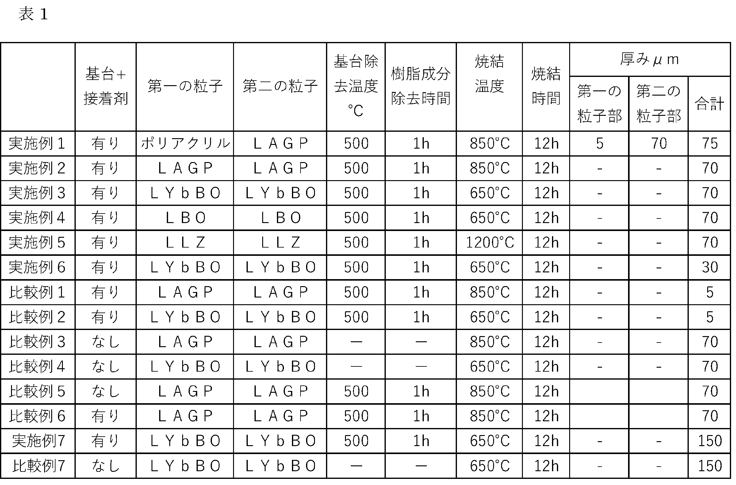
(実施例1)
実施例1は図4に示すシステムを使用した。基台としては、3μmのポリエステル(PET)製のシート(ルミラー東レ製)を用いた。乾燥後1μmになるように接着剤としてアクリル系粘着剤(T-50、東亞合成株式会社製)を基台に塗布したものを使用した。
また第一の粒子は2μmのポリアクリル樹脂粒子(MV1002日本触媒製)を使用し、第一の粒子部の厚みが5μmになるように塗工した。第一の粒子を塗工したのちのプレスの条件は、250kPaになるようにした。
また第二の粒子はLi1.5Al0.5Ge1.5P3O12(以下、LAGPとも表記する)粉末を用いて第二の粒子部の厚み70μmになるように塗工した。第二の粒子を塗工したのちのプレスの条件は、250kPaとして固体電解質基材を得た。
その後、図9に示すシステムを用いて、得られた固体電解質基材から樹脂成分である基台、粘着剤及び樹脂粒子を加熱により除去し固体電解質一体物を作製し、加圧した後に再度焼結し固体電解質層を得た。なお、基台の除去の加熱は、焼結雰囲気はAir、温度(1h維持)は500℃とした。また固体電解質層にするための焼結は850℃で行った。
Example 1
In Example 1, the system shown in Fig. 4 was used. A 3 μm polyester (PET) sheet (Lumirror, Toray) was used as the base. An acrylic adhesive (T-50, Toagosei Co., Ltd.) was applied to the base as the adhesive so that the thickness would be 1 μm after drying.
The first particles were polyacrylic resin particles (MV1002, manufactured by Nippon Shokubai) of 2 μm in size, and were applied so that the thickness of the first particle portion was 5 μm. The pressing condition after applying the first particles was set to 250 kPa.
The second particles were formed by coating with Li1.5Al0.5Ge1.5P3O12 (hereinafter also referred to as LAGP) powder so that the thickness of the second particle portion was 70 μm. After coating the second particles, the pressing condition was 250 kPa to obtain a solid electrolyte substrate.
Then, using the system shown in Fig. 9, the base, adhesive, and resin particles, which are resin components, were removed from the obtained solid electrolyte substrate by heating to produce a solid electrolyte integrated body, which was then pressed and sintered again to obtain a solid electrolyte layer. Note that the heating for removing the base was performed in an air sintering atmosphere at a temperature of 500°C (maintained for 1 h). Sintering to produce a solid electrolyte layer was performed at 850°C.
(実施例2)
基台と接着剤は実施例1と同じものを使用した。第一の粒子と第二の粒子は同じLAGPを用いた。そのため固体電解質基材は図8のシステムを用いて作製した。プレスの条件は、250kPaになるようにした。また、第一の粒子部及び第二の粒子部の合計厚みが表1に記載の値になるようにした。そのほかの条件は実施例1と同じにした。
Example 2
The base and adhesive were the same as those in Example 1. The first particles and the second particles used the same LAGP. Therefore, the solid electrolyte substrate was produced using the system of FIG. 8. The pressing conditions were set to 250 kPa. In addition, the total thickness of the first particle portion and the second particle portion was set to the value shown in Table 1. The other conditions were the same as those in Example 1.
(実施例3)
基台と接着剤は実施例1と同じものを使用した。第一の粒子と第二の粒子はLi5.9Yb0.81La0.09Zr0.1(BO3)3(キヤノン株式会社製。以下、LYb
BOとも表記する)を用いた。そのほかの条件は実施例2と同じにした。基台除去の条件等は表1に示す。
Example 3
The base and adhesive used were the same as those in Example 1. The first particles and the second particles were made of Li5.9Yb0.81La0.09Zr0.1 ( BO3 ) 3 (manufactured by Canon Inc.; hereinafter , referred to as LYb
The other conditions were the same as in Example 2. The conditions for removing the base are shown in Table 1.
(実施例4)
基台と接着剤は実施例1と同じものを使用した。第一の粒子と第二の粒子はLi3BO3(以下、LBOとも表記する)を用いた。そのほかの条件は実施例2と同じにした。基台除去の条件等は表1に示す。
Example 4
The base and adhesive used were the same as those in Example 1. The first particles and the second particles used were Li 3 BO 3 (hereinafter also referred to as LBO). The other conditions were the same as those in Example 2. The conditions for removing the base are shown in Table 1.
(実施例5)
基台と接着剤は実施例1と同じものを使用した。第一の粒子と第二の粒子はLi7La3Zr2O13(以下、LLZとも表記する)を用いた。そのほかの条件は実施例2と同じにした。基台除去の条件等は表1に示す。
Example 5
The base and adhesive used were the same as those in Example 1. The first particles and the second particles used were Li 7 La 3 Zr 2 O 13 (hereinafter also referred to as LLZ). The other conditions were the same as those in Example 2. The conditions for removing the base are shown in Table 1.
(実施例6)
基台と接着剤は実施例1と同じものを使用した。第一の粒子と第二の粒子はLYbBOを用いた。実施例3とは異なり第一の粒子部及び第二の粒子部の合計厚みが30μmになるように調整した。そのほかの条件は実施例2と同じにした。基台除去の条件等は表1に示す。
(Example 6)
The same base and adhesive as those in Example 1 were used. LYbBO was used for the first and second particles. Unlike Example 3, the total thickness of the first and second particle portions was adjusted to 30 μm. The other conditions were the same as those in Example 2. The conditions for removing the base are shown in Table 1.
(比較例1)
基台と接着剤は実施例1と同じものを使用した。第一の粒子と第二の粒子はLAGPを用いた。粒子部の合計厚み5μmになるように調整した。そのほかの条件は実施例2と同じにした。基台除去の条件等は表1に示す。
比較例1では、粒子部が薄いため、第二の粒子部が形成されなかった。
(Comparative Example 1)
The base and adhesive were the same as those in Example 1. LAGP was used for the first and second particles. The total thickness of the particle portion was adjusted to 5 μm. The other conditions were the same as those in Example 2. The conditions for removing the base are shown in Table 1.
In Comparative Example 1, the particle portion was thin, so that the second particle portion was not formed.
(比較例2)
基台と接着剤は実施例1と同じものを使用した。第一の粒子と第二の粒子はLYbBOを用いた。粒子部の合計厚み5μmになるように調整した。そのほかの条件は実施例2と同じにした。基台除去の条件等は表1に示す。
比較例2では、粒子部が薄いため、第二の粒子部が形成されなかった。
(Comparative Example 2)
The base and adhesive were the same as those in Example 1. LYbBO was used for the first and second particles. The total thickness of the particle portion was adjusted to 5 μm. The other conditions were the same as those in Example 2. The conditions for removing the base are shown in Table 1.
In Comparative Example 2, the particle portion was thin, so that the second particle portion was not formed.
(比較例3)
基台と接着剤を使用せず、LAGPのみで粒子部の合計厚み70μmになるように調整し固体電解質基材を得た。プレスの条件は、12000kPaになるようにした。そのほかは実施例2と同様にした。
(Comparative Example 3)
A solid electrolyte substrate was obtained by adjusting the total thickness of the particles to 70 μm using only LAGP without using a base or adhesive. The pressing conditions were set to 12000 kPa. The rest were the same as in Example 2.
(比較例4)
基台と接着剤を使用せず、LYbBOのみで粒子部の合計厚み70μmになるように調整した。プレスの条件は、12000kPaになるようにした。そのほかは実施例3と同様にした。
(Comparative Example 4)
The total thickness of the particle part was adjusted to 70 μm using only LYbBO without using a base or adhesive. The pressing conditions were set to 12000 kPa. The rest were the same as in Example 3.
(比較例5)
基台は実施例2と同じものを使用したが、接着剤は使用しなかった。粒子はLAGPを用いた。プレスの条件は、250kPaになるようにした。そのほかの条件は実施例2と同じにした。したがって、比較例5では、第一の粒子部が形成されず、LAGPによる圧粉体のみが基台に形成された。
(Comparative Example 5)
The same base as in Example 2 was used, but no adhesive was used. LAGP was used as particles. The pressing conditions were set to 250 kPa. The other conditions were the same as in Example 2. Therefore, in Comparative Example 5, the first particle portion was not formed, and only a compact made of LAGP was formed on the base.
(比較例6)
基台及び接着剤は実施例2と同じものを使用した。粒子はLAGPを用いた。第二の粒子は使用せず、第一の粒子部が分散した接着剤の厚みが70μmになるように、250k
Paでプレスした。そのほかの条件は実施例2と同じにした。したがって、比較例6では、第二の粒子部が形成されなかった。
(Comparative Example 6)
The base and adhesive were the same as those in Example 2. LAGP particles were used. No second particles were used, and the adhesive was heated at 250 kPa so that the thickness of the adhesive in which the first particles were dispersed was 70 μm.
The pressing was performed at 10 Pa. The other conditions were the same as those in Example 2. Therefore, in Comparative Example 6, the second particle portion was not formed.
(実施例7)
基台と接着剤は実施例1と同じものを使用した。粒子はLYbBOを用いた。第一の粒子部及び第二の粒子部の合計厚み150μmになるように調整した。基台除去の条件等は表1に示す。そのほかの条件は実施例2と同じにした。
(Example 7)
The same base and adhesive as those in Example 1 were used. LYbBO was used as particles. The total thickness of the first particle portion and the second particle portion was adjusted to 150 μm. The conditions for removing the base are shown in Table 1. The other conditions were the same as those in Example 2.
(比較例7)
基台と接着剤を使用せずに、第一の粒子と第二の粒子はLYbBOを用いた。粒子部の合計厚み150μmになるように調整し固体電解質基材を得た。焼結などの条件等は表1に示す。プレスの条件は、12000kPaになるようにした。そのほかは実施例3と同様にした。
(Comparative Example 7)
The first and second particles were made of LYbBO without using a base and an adhesive. The total thickness of the particle portion was adjusted to 150 μm to obtain a solid electrolyte substrate. The sintering conditions are shown in Table 1. The pressing conditions were set to 12000 kPa. The rest were the same as in Example 3.
厚みに関しては、図8のシステムを用いて作製した例は、合計の厚みのみ記載する。
Regarding thickness, only the total thickness is shown for the examples produced using the system of FIG.
表2に実施例、比較例、参考例の評価結果を示す。また評価方法について説明する。 Table 2 shows the evaluation results for the Examples, Comparative Examples, and Reference Examples. The evaluation method is also explained.
・取扱性
基台除去前(焼成前)で得られた平板形状の固体電解質基材(10mm角)の真ん中をピンセットでつかみ亀裂が入るかどうかで評価を行った。亀裂の入らないものをAとし、亀裂が入らないが、そりが出たものをBとし、亀裂の入ったものをCとした。
Handling: The center of the plate-shaped solid electrolyte substrate (10 mm square) obtained before removing the base (before firing) was held with tweezers and evaluated for cracks. Those without cracks were rated as A, those without cracks but with warping were rated as B, and those with cracks were rated as C.
・抵抗値の測定
基台除去後、焼結で得られた平板形状の焼結体の上下面に、(株)真空デバイス製マグネトロンスパッタ装置MSP-10を用いて、Φ3で金の電極を成膜し、交流インピーダンス測定を行うための試料とした。測定にはSolartronAnalytical社製のポテンショ/ガルバノスタットSI1287A及び周波数応答アナライザー1255
Bを使用した。
測定条件は、室温、周波数1MHz~0.1Hzとした。抵抗値は、インピーダンス測定で得られた複素インピーダンスプロットから算出した。Z並列回路で求めた抵抗値(Ω)10000以下をA、抵抗値10000を超えるものをB、リークし測定できなかったものをCとした。また亀裂の入ったものについては測定できないためCとした。
Measurement of resistance value After removing the base, gold electrodes of Φ3 were formed on the top and bottom surfaces of the flat sintered body obtained by sintering using a magnetron sputtering device MSP-10 manufactured by Vacuum Device Co., Ltd., to prepare a sample for measuring AC impedance. For the measurement, a potentio/galvanostat SI1287A and a frequency response analyzer 1255 manufactured by Solartron Analytical Co., Ltd. were used.
B was used.
The measurement conditions were room temperature and a frequency of 1 MHz to 0.1 Hz. The resistance value was calculated from a complex impedance plot obtained by impedance measurement. A resistance value (Ω) of 10,000 or less obtained in a Z-parallel circuit was rated A, a resistance value exceeding 10,000 was rated B, and a leak that could not be measured was rated C. In addition, a cracked specimen was rated C because it could not be measured.
・第一の粒子層と第二の粒子層の面積割合の差
BIB-SEMの撮影と画像処理により求めた。
<BIB-SEMの撮影方法>
固体電解質基材中の面積割合の判定においては、BIB-SEM画像を用いた。以下にBIB-SEMの撮影条件について説明する。
基盤(Al箔)上に作製した固体電解質基材を真空包装及び等方圧加圧したサンプルを準備した。サンプルをワイヤーソー(DWS3400/ワイヤー径170μm・ダイヤモンド径30μm)で基台、第1の粒子部及び第二の粒子部の積層方向に切断し、切断面に対してArによるブロードイオンビームで断面加工(JEOL製SM-09010 Cross Section Polisher)した。断面加工の条件は、電圧6kV、電流150~200mAとした。BIB-SEM画像として、積層方向の断面を得て、断面観察を行う。
Difference in area ratio between the first particle layer and the second particle layer was determined by photographing with a BIB-SEM and processing the image.
<BIB-SEM photography method>
The area ratio in the solid electrolyte substrate was determined using BIB-SEM images. The photographing conditions for the BIB-SEM are explained below.
A sample was prepared by vacuum packaging and isostatically pressing a solid electrolyte substrate prepared on a base (Al foil). The sample was cut in the stacking direction of the base, the first particle portion, and the second particle portion with a wire saw (DWS3400/wire diameter 170 μm,
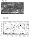
断面部を電子顕微鏡(ULTRA55)により以下の条件で撮影した。撮影した画像の例(実施例2)を図10A及び10Bに示す。
検出器:ESB(反射電子像)
観察条件:加速電圧3kV
倍率:1000倍
フィルター:ESBフィルターに1500Vのバイアス印加
The cross-section was photographed using an electron microscope (ULTRA55) under the following conditions. Examples of the photographed images (Example 2) are shown in Figures 10A and 10B.
Detector: ESB (backscattered electron beam)
Observation conditions:
Magnification: 1000x Filter: ESB filter with 1500V bias applied
次に、SEM―EDX(Bruker社製 XFlash Detector 630M)により、基台上の各粒子の元素、組成分析を行い、接着剤成分と、固体電解質粒子とを識別した。
基台、接着剤成分及び固体電解質粒子の識別は、具体的には、基台、接着剤成分をX線回折(XRD)等で分析し、基台、接着剤成分を構成する物質の同定を行う。その後、固体電解質粒子に含まれる特有の元素をそれぞれSEM―EDXで検出し、識別する。
Next, the elements and composition of each particle on the base were analyzed by SEM-EDX (XFlash Detector 630M manufactured by Bruker Corporation) to distinguish between adhesive components and solid electrolyte particles.
Specifically, the base, adhesive components, and solid electrolyte particles are identified by analyzing the base and adhesive components using X-ray diffraction (XRD) or the like to identify the materials that make up the base and adhesive components. Then, the specific elements contained in the solid electrolyte particles are detected and identified using SEM-EDX.
なお、第一の粒子部と第二の粒子部は以下のようにして分ける。上述した通り、接着剤によって保持されている粒子の最大高さまでの位置を第一の粒子部とする。したがって、SEM―EDXにより、接着剤に含まれる特有の元素、具体的には炭素C成分を観測することにより、接着剤の位置を確認する。そして、接着剤によって保持されている粒子を選択し、これらの最大高さまでの位置を第一の粒子部とする。さらに、第一の粒子部の上の接着剤に接していない粒子の群を第二の粒子部とする。 The first particle portion and the second particle portion are divided as follows. As mentioned above, the position of the particles held by the adhesive up to their maximum height is defined as the first particle portion. Therefore, the position of the adhesive is confirmed by observing the specific elements contained in the adhesive, specifically the carbon C component, using SEM-EDX. Then, the particles held by the adhesive are selected, and the position of these up to their maximum height is defined as the first particle portion. Furthermore, the group of particles above the first particle portion that are not in contact with the adhesive is defined as the second particle portion.
<単位深さあたりの固体電解質粒子の割合の算出方法>
上述の条件により撮影したBIB-SEM画像から、固体電解質粒子の占める面積割合を検出した。
はじめにBIB-SEM画像を平均明度100、標準偏差±30となるように正規化した。基台上の固体電解質粒子をカウントするために、上記正規化した画像から基台上の粒子層のみを表す画像を、画像中の全粒子を含むように切り出す。切り出した画像の例を、図10Aに示す。
<Method of calculating the ratio of solid electrolyte particles per unit depth>
The area ratio of the solid electrolyte particles was detected from the BIB-SEM images taken under the above conditions.
First, the BIB-SEM image was normalized to have an average brightness of 100 and a standard deviation of ±30. In order to count the solid electrolyte particles on the base, an image showing only the particle layer on the base was cut out from the normalized image so as to include all particles in the image. An example of the cut-out image is shown in FIG. 10A.
切り出した画像を、明度70を閾値として2値化した画像を得た。ノイズ除去の目的で、白画素で囲まれた領域を白で塗りつぶした後、モルフォロジー変換のオープニング処理
をカーネルサイズ3×3画素にて行い、ノイズ除去後の画像を得た。ノイズ除去後の画像の例を図10Bに示す。
The cut-out image was binarized with a threshold value of
続いて、上記で得られた画像図10Bにおける各縦列の白画素の最上部の位置と最下部の位置をそれぞれ求め、記録する。各縦列の白画素の最上部の位置は固体電解質層の最上面の位置を示す値であり、各縦列の白画素の最下部の位置は固体電解質層の最下面の位置を示す値である。またSEM画像より固体電解質層の厚みは70μmと分かっており、厚みに対し5μm刻みで固体電解質が占める面積割合を計算した。
具体的な計算方法は、図10Bに示されるように、横300μm、縦70μmの固体電解質層において、横300μm、縦5μm刻みで、白部(粒子部)の面積割合を算出した。なお、d1及びd2は、横300μm、縦5μm刻みで測定した面積割合の平均値を採用する。
その結果が図11になる。これより、第一の粒子部と第二の粒子部の面積割合の差を求めることができる。なお、図10Bの70μmの位置(下から5μm)が第一の粒子部であり、その他が第二の粒子部である。また、図11の縦列の面積割合の値に100を乗じた数値がd1及びd2となる面積%の数値になる。図11ではd1は84%であり、d2は88%であり、面積割合の差(第二の粒子部-第一の粒子部)は4%であった。
Next, the top and bottom positions of the white pixels in each vertical column in the image (FIG. 10B) obtained above are determined and recorded. The top position of the white pixels in each vertical column is a value indicating the position of the top surface of the solid electrolyte layer, and the bottom position of the white pixels in each vertical column is a value indicating the position of the bottom surface of the solid electrolyte layer. The thickness of the solid electrolyte layer was found to be 70 μm from the SEM image, and the area ratio of the solid electrolyte to the thickness was calculated in 5 μm increments.
Specifically, the area ratio of the white portion (particle portion) was calculated in increments of 300 μm horizontally and 5 μm vertically in a solid electrolyte layer of 300 μm horizontally and 70 μm vertically as shown in FIG. 10B. Note that d1 and d2 are the average values of the area ratios measured in increments of 300 μm horizontally and 5 μm vertically.
The results are shown in FIG. 11. From this, the difference in area ratio between the first particle portion and the second particle portion can be obtained. The position at 70 μm (5 μm from the bottom) in FIG. 10B is the first particle portion, and the rest is the second particle portion. The area ratio values in the vertical columns in FIG. 11 multiplied by 100 are the area percentage values for d1 and d2. In FIG. 11, d1 is 84%, d2 is 88%, and the difference in area ratio (second particle portion - first particle portion) was 4%.

面積割合の差は、d2-d1を示す。
The difference in area ratio is d2-d1.
(実施例8)
実施例2で作製した固体電解質層を用いて、二次電池を作製した。特開2019-137060に基づきLCOとLAGPを使用した正極電極を作製した。また負極は、インジウム箔(厚み50μm)を用いた。正極集電体として、アルミニウム箔(厚み20μm)
を用いた。また、負極集電体として、銅箔(厚み20μm)を用いた。
上述の材料を、正極集電体、正極、固体電解質層、負極、負極集電体の順で積層し、予め集電体に溶接した取出し電極用のタブリードをラミネート外部に配置するように、アルミラミネートフィルム内に梱包した。そして、真空包装機によりラミネートセル型に成形し、等方圧加圧装置で加圧(196MPa)して全固体二次電池を作製した。室温で電池の駆動できることを確認した。
(Example 8)
A secondary battery was produced using the solid electrolyte layer produced in Example 2. A positive electrode was produced using LCO and LAGP based on JP 2019-137060. Indium foil (
In addition, a copper foil (thickness: 20 μm) was used as a negative electrode current collector.
The above-mentioned materials were laminated in the order of a positive electrode collector, a positive electrode, a solid electrolyte layer, a negative electrode, and a negative electrode collector, and packaged in an aluminum laminate film so that a tab lead for an extraction electrode previously welded to the current collector was placed outside the laminate. Then, the laminate was formed into a laminate cell type using a vacuum packaging machine, and pressurized (196 MPa) using an isostatic pressure pressurizing device to produce an all-solid-state secondary battery. It was confirmed that the battery could be operated at room temperature.
(実施例9)
実施例3で作製した固体電解質層を用いて、二次電池を作製した。特開2019-137060に基づきLCOとLYbBOを使用した正極電極を作製した。そのほかは実施例7と同様に全固体二次電池を作製し、室温で電池の駆動できることを確認した。
Example 9
A secondary battery was produced using the solid electrolyte layer produced in Example 3. A positive electrode using LCO and LYbBO was produced based on JP 2019-137060 A solid-state secondary battery was otherwise produced in the same manner as in Example 7, and it was confirmed that the battery could be operated at room temperature.
本開示は以下の構成又は方法に関する。
(構成1)
固体電解質の製造に用いられる固体電解質基材であって、
基台と、
接着剤によって前記基台に弾性保持された第一の粒子部と、
前記第一の粒子部に対して積層して保持された、固体電解質粒子の圧粉体を含む第二の粒子部と、
を有する固体電解質基材。
(構成2)
前記固体電解質粒子が酸化物系の固体電解質粒子を含有する、構成1に記載の固体電解質基材。
(構成3)
前記第一の粒子部及び前記第二の粒子部の合計の厚みが100μm未満である、構成1又は2に記載の固体電解質基材。
(構成4)
前記第一の粒子部が固体電解質粒子を含む、構成1~3のいずれかに記載の固体電解質基材。
(構成5)
走査型電子顕微鏡による前記固体電解質基材の断面観察において、
前記第一の粒子部の面積割合(%)をd1とし、前記第二の粒子部の面積割合(%)をd2としたとき、d1とd2とが異なる、構成1~4のいずれかに記載の固体電解質基材。
(構成6)
前記d1及び前記d2が、d1<d2を満たす、構成5に記載の固体電解質基材。
(構成7)
前記d1及び前記d2の差分が、2%以上である、構成5又は6に記載の固体電解質基材。
(構成8)
前記接着剤は粘着性を有する、構成1~7のいずれかに記載の固体電解質基材。
(構成9)
前記接着剤の厚みが0.5~5μmである、構成1~8のいずれかに記載の固体電解質基材。
(構成10)
固体電解質の製造に用いられる固体電解質基材であって、
基台と、
該基台上の接着剤の層と、
該接着剤に分散して保持された第一の粒子部と、
該第一の粒子部に対して積層して保持された、固体電解質粒子の圧粉体を含む第二の
粒子部と、
を有する固体電解質基材。
(構成11)
構成1~10のいずれかに記載の固体電解質基材から前記基台の少なくとも一部を除去した固体電解質。
(構成12)
固体電解質と前記固体電解質に配された電極と、を備えた二次電池であって、
該固体電解質は構成11に記載の固体電解質である、二次電池。
(方法13)
基台、接着剤、第一の粒子部及び第二の粒子部がこの順に積層された固体電解質基材の製造方法であって、
第二の粒子部が固体電解質粒子を含み、
前記製造方法は、
前記接着剤を備えた前記基台を準備する準備工程と、
前記接着剤の表面に第一の粒子を配置する第1工程と、
前記第一の粒子に対して圧力をかけ前記第一の粒子部を作製する第2工程と、
前記第一の粒子部の表面に第二の粒子を配置する第3工程と、
前記第二の粒子に対して圧力をかけ前記第二の粒子部を作製し前記固体電解質基材を得る第4工程と、
を有する、固体電解質基材の製造方法。
(方法14)
基台、接着剤、粒子部がこの順に積層された固体電解質基材の製造方法であって、
前記接着剤を備えた前記基台を準備する工程と、
前記接着剤の表面に固体電解質粒子を配置する工程と、
前記固体電解質粒子に対して圧力をかけ、前記粒子部を作製し前記固体電解質基材を得る工程と、
を有する固体電解質基材の製造方法。
(方法15)
前記接着剤が粘着性を有する、方法13又は14に記載の固体電解質基材の製造方法。
The present disclosure relates to the following configurations or methods.
(Configuration 1)
A solid electrolyte substrate used in the production of a solid electrolyte, comprising:
The base and
A first particle portion elastically held on the base by an adhesive;
a second particle portion including a compact of solid electrolyte particles stacked and held on the first particle portion;
A solid electrolyte substrate having
(Configuration 2)
2. The solid electrolyte substrate according to
(Configuration 3)
3. The solid electrolyte substrate according to
(Configuration 4)
4. The solid electrolyte substrate according to any one of
(Configuration 5)
In observing a cross section of the solid electrolyte substrate using a scanning electron microscope,
5. The solid electrolyte base material according to any one of
(Configuration 6)
The solid electrolyte substrate according to aspect 5, wherein d1 and d2 satisfy d1<d2.
(Configuration 7)
The solid electrolyte substrate according to aspect 5 or 6, wherein the difference between d1 and d2 is 2% or more.
(Configuration 8)
The solid electrolyte substrate according to any one of
(Configuration 9)
9. The solid electrolyte substrate according to any one of
(Configuration 10)
A solid electrolyte substrate used in the production of a solid electrolyte, comprising:
The base and
a layer of adhesive on the base;
a first particle portion dispersed and held in the adhesive;
a second particle portion including a compact of solid electrolyte particles stacked and held on the first particle portion;
A solid electrolyte substrate having
(Configuration 11)
A solid electrolyte obtained by removing at least a portion of the base from the solid electrolyte substrate according to any one of
(Configuration 12)
A secondary battery comprising a solid electrolyte and an electrode disposed on the solid electrolyte,
12. A secondary battery, wherein the solid electrolyte is the solid electrolyte according to
(Method 13)
A method for producing a solid electrolyte substrate in which a base, an adhesive, a first particle portion, and a second particle portion are laminated in this order, comprising the steps of:
the second particle portion includes solid electrolyte particles;
The manufacturing method includes:
a preparation step of preparing the base having the adhesive;
a first step of disposing first particles on a surface of the adhesive;
a second step of applying pressure to the first particles to produce the first particle portion;
a third step of disposing second particles on the surfaces of the first particle portions;
a fourth step of applying pressure to the second particles to produce the second particle portion and obtain the solid electrolyte base material;
The method for producing a solid electrolyte substrate comprising the steps of:
(Method 14)
A method for producing a solid electrolyte substrate in which a base, an adhesive, and a particle portion are laminated in this order, comprising the steps of:
providing the base with the adhesive;
disposing solid electrolyte particles on a surface of the adhesive;
applying pressure to the solid electrolyte particles to produce the particle portion and obtain the solid electrolyte base material;
The method for producing a solid electrolyte substrate comprising the steps of:
(Method 15)
15. The method for producing a solid electrolyte substrate according to
Claims (15)
基台と、
接着剤によって前記基台に弾性保持された第一の粒子部と、
前記第一の粒子部に対して積層して保持された、固体電解質粒子の圧粉体を含む第二の粒子部と、
を有する固体電解質基材。 A solid electrolyte substrate used in the production of a solid electrolyte, comprising:
The base and
A first particle portion elastically held to the base by an adhesive;
a second particle portion including a compact of solid electrolyte particles stacked and held on the first particle portion;
A solid electrolyte substrate having
前記第一の粒子部の面積割合(%)をd1とし、前記第二の粒子部の面積割合(%)をd2としたとき、d1とd2とが異なる、請求項1に記載の固体電解質基材。 In observing a cross section of the solid electrolyte substrate using a scanning electron microscope,
2. The solid electrolyte base material according to claim 1, wherein d1 is an area ratio (%) of the first particle portion and d2 is an area ratio (%) of the second particle portion, and d1 and d2 are different from each other.
基台と、
該基台上の接着剤の層と、
該接着剤に分散して保持された第一の粒子部と、
該第一の粒子部に対して積層して保持された、固体電解質粒子の圧粉体を含む第二の粒子部と、
を有する固体電解質基材。 A solid electrolyte substrate used in the production of a solid electrolyte, comprising:
The base and
a layer of adhesive on the base;
a first particle portion dispersed and held in the adhesive;
a second particle portion including a compact of solid electrolyte particles stacked and held on the first particle portion;
A solid electrolyte substrate having
該固体電解質は請求項11に記載の固体電解質である、二次電池。 A secondary battery comprising a solid electrolyte and an electrode disposed on the solid electrolyte,
A secondary battery, wherein the solid electrolyte is the solid electrolyte according to claim 11.
第二の粒子部が固体電解質粒子を含み、
前記製造方法は、
前記接着剤を備えた前記基台を準備する準備工程と、
前記接着剤の表面に第一の粒子を配置する第1工程と、
前記第一の粒子に対して圧力をかけ前記第一の粒子部を作製する第2工程と、
前記第一の粒子部の表面に第二の粒子を配置する第3工程と、
前記第二の粒子に対して圧力をかけ前記第二の粒子部を作製し前記固体電解質基材を得る第4工程と、
を有する、固体電解質基材の製造方法。 A method for producing a solid electrolyte substrate in which a base, an adhesive, a first particle portion, and a second particle portion are laminated in this order, comprising the steps of:
the second particle portion includes solid electrolyte particles;
The manufacturing method includes:
a preparation step of preparing the base having the adhesive;
a first step of disposing first particles on a surface of the adhesive;
a second step of applying pressure to the first particles to produce the first particle portion;
a third step of disposing second particles on the surfaces of the first particle portions;
a fourth step of applying pressure to the second particles to produce the second particle portion and obtain the solid electrolyte base material;
The method for producing a solid electrolyte substrate comprising the steps of:
前記接着剤を備えた前記基台を準備する工程と、
前記接着剤の表面に固体電解質粒子を配置する工程と、
前記固体電解質粒子に対して圧力をかけ、前記粒子部を作製し前記固体電解質基材を得る工程と、
を有する固体電解質基材の製造方法。 A method for producing a solid electrolyte substrate in which a base, an adhesive, and a particle portion are laminated in this order, comprising the steps of:
providing the base with the adhesive;
disposing solid electrolyte particles on a surface of the adhesive;
applying pressure to the solid electrolyte particles to produce the particle portion and obtain the solid electrolyte base material;
The method for producing a solid electrolyte substrate comprising the steps of:
Priority Applications (3)
| Application Number | Priority Date | Filing Date | Title |
|---|---|---|---|
| JP2023148390A JP2025041222A (en) | 2023-09-13 | 2023-09-13 | Solid electrolyte substrate, solid electrolyte, secondary battery, and method for producing solid electrolyte substrate |
| PCT/JP2024/030247 WO2025057710A1 (en) | 2023-09-13 | 2024-08-26 | Solid electrolyte base material, solid electrolyte, secondary battery, and method for manufacturing solid electrolyte base material |
| CN202480058119.6A CN121844423A (en) | 2023-09-13 | 2024-08-26 | Solid electrolyte substrate, solid electrolyte, secondary battery, and method for manufacturing solid electrolyte substrate. |
Applications Claiming Priority (1)
| Application Number | Priority Date | Filing Date | Title |
|---|---|---|---|
| JP2023148390A JP2025041222A (en) | 2023-09-13 | 2023-09-13 | Solid electrolyte substrate, solid electrolyte, secondary battery, and method for producing solid electrolyte substrate |
Publications (1)
| Publication Number | Publication Date |
|---|---|
| JP2025041222A true JP2025041222A (en) | 2025-03-26 |
Family
ID=95022168
Family Applications (1)
| Application Number | Title | Priority Date | Filing Date |
|---|---|---|---|
| JP2023148390A Pending JP2025041222A (en) | 2023-09-13 | 2023-09-13 | Solid electrolyte substrate, solid electrolyte, secondary battery, and method for producing solid electrolyte substrate |
Country Status (3)
| Country | Link |
|---|---|
| JP (1) | JP2025041222A (en) |
| CN (1) | CN121844423A (en) |
| WO (1) | WO2025057710A1 (en) |
Family Cites Families (9)
| Publication number | Priority date | Publication date | Assignee | Title |
|---|---|---|---|---|
| JP2012221887A (en) | 2011-04-13 | 2012-11-12 | Toyota Motor Corp | Method for producing solid state battery material |
| JP6088896B2 (en) | 2013-04-18 | 2017-03-01 | 積水化学工業株式会社 | Manufacturing method of all solid state battery |
| JP6310717B2 (en) * | 2014-02-10 | 2018-04-11 | 古河機械金属株式会社 | Solid electrolyte sheet and all solid-state lithium ion battery |
| JP7301548B2 (en) * | 2018-02-14 | 2023-07-03 | キヤノン株式会社 | Electrode sheet manufacturing method and solid electrolyte sheet manufacturing method |
| JP7277163B2 (en) | 2018-02-14 | 2023-05-18 | キヤノン株式会社 | Material layer manufacturing method, three-dimensional object manufacturing method, material layer, laminate, material layer forming apparatus, and layered manufacturing system |
| CN111900310B (en) * | 2020-08-07 | 2021-11-12 | 北京科技大学 | Preparation method of high-density high-ionic conductivity electrolyte diaphragm for all-solid-state battery |
| JP2022130301A (en) | 2021-02-25 | 2022-09-06 | キヤノン株式会社 | Solid electrolyte, active material layer, electrolyte layer and secondary battery |
| CN113314767B (en) * | 2021-05-28 | 2022-04-15 | 中南大学 | All-solid-state battery preparation method and all-solid-state battery |
| JP2023148390A (en) | 2022-03-30 | 2023-10-13 | 株式会社アドバンスト・メディア | Voice recognition device, voice recognition method and program |
-
2023
- 2023-09-13 JP JP2023148390A patent/JP2025041222A/en active Pending
-
2024
- 2024-08-26 CN CN202480058119.6A patent/CN121844423A/en active Pending
- 2024-08-26 WO PCT/JP2024/030247 patent/WO2025057710A1/en active Pending
Also Published As
| Publication number | Publication date |
|---|---|
| CN121844423A (en) | 2026-04-10 |
| WO2025057710A1 (en) | 2025-03-20 |
Similar Documents
| Publication | Publication Date | Title |
|---|---|---|
| US10164287B2 (en) | All-solid battery and manufacturing method therefor | |
| JP5803700B2 (en) | Inorganic all-solid secondary battery | |
| JP5741689B2 (en) | All-solid battery and method for manufacturing the same | |
| KR102478029B1 (en) | Garnet materials for li secondary batteries | |
| WO2018123479A1 (en) | Lithium ion cell and method for manufacturing same | |
| US12080847B2 (en) | All-solid-state battery | |
| JP5144846B2 (en) | Method for producing green sheet laminate | |
| JPWO2013008677A1 (en) | All-solid battery and method for manufacturing the same | |
| KR20090081438A (en) | A negative electrode for a lithium secondary battery, a lithium secondary battery using the negative electrode, a film forming material used for forming the negative electrode, and a method for producing the negative electrode | |
| WO2013038880A1 (en) | All-solid-state cell and method for producing same | |
| WO2013100000A1 (en) | All-solid-state battery, and manufacturing method therefor | |
| US20220021022A1 (en) | All-solid-state secondary battery | |
| WO2013100001A1 (en) | All-solid cell and method for manufacturing same | |
| JP2010170854A (en) | Method of manufacturing positive electrode for nonaqueous electrolyte battery, positive electrode for nonaqueous electrolyte battery, and nonaqueous electrolyte battery | |
| JP2025041222A (en) | Solid electrolyte substrate, solid electrolyte, secondary battery, and method for producing solid electrolyte substrate | |
| KR20180041474A (en) | A method of manufacturing solide eflectolyte thin using tape casting | |
| JP6192540B2 (en) | All-solid battery and method for manufacturing the same | |
| JP2009181876A (en) | Method of manufacturing laminate for lithium ion secondary battery | |
| JPWO2019004001A1 (en) | Ion-conductive composite body, all-solid-state battery, and methods for producing the same | |
| JP2012221887A (en) | Method for producing solid state battery material | |
| US20260094865A1 (en) | Electrode base material, electrode base material laminate, electrode, secondary battery, and methods for manufacturing same | |
| KR102801530B1 (en) | Method for manufacturing an oxide-based multilayer all-solid-state battery | |
| JP2025030898A (en) | Electrode substrate, electrode substrate laminate, electrode and secondary battery, and method for producing same | |
| JP2025151669A (en) | Solid electrolyte membrane, lithium ion secondary battery, and lithium ion secondary battery module | |
| JP2025151670A (en) | Method for manufacturing a solid electrolyte membrane and method for manufacturing a lithium-ion secondary battery |