JP2021081081A - Heat transfer pipe and heat exchanger - Google Patents
Heat transfer pipe and heat exchanger Download PDFInfo
- Publication number
- JP2021081081A JP2021081081A JP2019205903A JP2019205903A JP2021081081A JP 2021081081 A JP2021081081 A JP 2021081081A JP 2019205903 A JP2019205903 A JP 2019205903A JP 2019205903 A JP2019205903 A JP 2019205903A JP 2021081081 A JP2021081081 A JP 2021081081A
- Authority
- JP
- Japan
- Prior art keywords
- flow path
- heat transfer
- transfer tube
- heat exchanger
- cross
- Prior art date
- Legal status (The legal status is an assumption and is not a legal conclusion. Google has not performed a legal analysis and makes no representation as to the accuracy of the status listed.)
- Pending
Links
Images


Classifications
-
- F—MECHANICAL ENGINEERING; LIGHTING; HEATING; WEAPONS; BLASTING
- F28—HEAT EXCHANGE IN GENERAL
- F28D—HEAT-EXCHANGE APPARATUS, NOT PROVIDED FOR IN ANOTHER SUBCLASS, IN WHICH THE HEAT-EXCHANGE MEDIA DO NOT COME INTO DIRECT CONTACT
- F28D1/00—Heat-exchange apparatus having stationary conduit assemblies for one heat-exchange medium only, the media being in contact with different sides of the conduit wall, in which the other heat-exchange medium is a large body of fluid, e.g. domestic or motor car radiators
- F28D1/02—Heat-exchange apparatus having stationary conduit assemblies for one heat-exchange medium only, the media being in contact with different sides of the conduit wall, in which the other heat-exchange medium is a large body of fluid, e.g. domestic or motor car radiators with heat-exchange conduits immersed in the body of fluid
- F28D1/04—Heat-exchange apparatus having stationary conduit assemblies for one heat-exchange medium only, the media being in contact with different sides of the conduit wall, in which the other heat-exchange medium is a large body of fluid, e.g. domestic or motor car radiators with heat-exchange conduits immersed in the body of fluid with tubular conduits
- F28D1/053—Heat-exchange apparatus having stationary conduit assemblies for one heat-exchange medium only, the media being in contact with different sides of the conduit wall, in which the other heat-exchange medium is a large body of fluid, e.g. domestic or motor car radiators with heat-exchange conduits immersed in the body of fluid with tubular conduits the conduits being straight
-
- F—MECHANICAL ENGINEERING; LIGHTING; HEATING; WEAPONS; BLASTING
- F28—HEAT EXCHANGE IN GENERAL
- F28F—DETAILS OF HEAT-EXCHANGE AND HEAT-TRANSFER APPARATUS, OF GENERAL APPLICATION
- F28F1/00—Tubular elements; Assemblies of tubular elements
- F28F1/10—Tubular elements and assemblies thereof with means for increasing heat-transfer area, e.g. with fins, with projections, with recesses
- F28F1/40—Tubular elements and assemblies thereof with means for increasing heat-transfer area, e.g. with fins, with projections, with recesses the means being only inside the tubular element
-
- F—MECHANICAL ENGINEERING; LIGHTING; HEATING; WEAPONS; BLASTING
- F25—REFRIGERATION OR COOLING; COMBINED HEATING AND REFRIGERATION SYSTEMS; HEAT PUMP SYSTEMS; MANUFACTURE OR STORAGE OF ICE; LIQUEFACTION SOLIDIFICATION OF GASES
- F25B—REFRIGERATION MACHINES, PLANTS OR SYSTEMS; COMBINED HEATING AND REFRIGERATION SYSTEMS; HEAT PUMP SYSTEMS
- F25B13/00—Compression machines, plants or systems, with reversible cycle
-
- F—MECHANICAL ENGINEERING; LIGHTING; HEATING; WEAPONS; BLASTING
- F25—REFRIGERATION OR COOLING; COMBINED HEATING AND REFRIGERATION SYSTEMS; HEAT PUMP SYSTEMS; MANUFACTURE OR STORAGE OF ICE; LIQUEFACTION SOLIDIFICATION OF GASES
- F25B—REFRIGERATION MACHINES, PLANTS OR SYSTEMS; COMBINED HEATING AND REFRIGERATION SYSTEMS; HEAT PUMP SYSTEMS
- F25B39/00—Evaporators; Condensers
- F25B39/02—Evaporators
- F25B39/028—Evaporators having distributing means
-
- F—MECHANICAL ENGINEERING; LIGHTING; HEATING; WEAPONS; BLASTING
- F25—REFRIGERATION OR COOLING; COMBINED HEATING AND REFRIGERATION SYSTEMS; HEAT PUMP SYSTEMS; MANUFACTURE OR STORAGE OF ICE; LIQUEFACTION SOLIDIFICATION OF GASES
- F25B—REFRIGERATION MACHINES, PLANTS OR SYSTEMS; COMBINED HEATING AND REFRIGERATION SYSTEMS; HEAT PUMP SYSTEMS
- F25B41/00—Fluid-circulation arrangements
- F25B41/20—Disposition of valves, e.g. of on-off valves or flow control valves
- F25B41/24—Arrangement of shut-off valves for disconnecting a part of the refrigerant cycle, e.g. an outdoor part
-
- F—MECHANICAL ENGINEERING; LIGHTING; HEATING; WEAPONS; BLASTING
- F28—HEAT EXCHANGE IN GENERAL
- F28D—HEAT-EXCHANGE APPARATUS, NOT PROVIDED FOR IN ANOTHER SUBCLASS, IN WHICH THE HEAT-EXCHANGE MEDIA DO NOT COME INTO DIRECT CONTACT
- F28D1/00—Heat-exchange apparatus having stationary conduit assemblies for one heat-exchange medium only, the media being in contact with different sides of the conduit wall, in which the other heat-exchange medium is a large body of fluid, e.g. domestic or motor car radiators
- F28D1/02—Heat-exchange apparatus having stationary conduit assemblies for one heat-exchange medium only, the media being in contact with different sides of the conduit wall, in which the other heat-exchange medium is a large body of fluid, e.g. domestic or motor car radiators with heat-exchange conduits immersed in the body of fluid
- F28D1/04—Heat-exchange apparatus having stationary conduit assemblies for one heat-exchange medium only, the media being in contact with different sides of the conduit wall, in which the other heat-exchange medium is a large body of fluid, e.g. domestic or motor car radiators with heat-exchange conduits immersed in the body of fluid with tubular conduits
- F28D1/053—Heat-exchange apparatus having stationary conduit assemblies for one heat-exchange medium only, the media being in contact with different sides of the conduit wall, in which the other heat-exchange medium is a large body of fluid, e.g. domestic or motor car radiators with heat-exchange conduits immersed in the body of fluid with tubular conduits the conduits being straight
- F28D1/0535—Heat-exchange apparatus having stationary conduit assemblies for one heat-exchange medium only, the media being in contact with different sides of the conduit wall, in which the other heat-exchange medium is a large body of fluid, e.g. domestic or motor car radiators with heat-exchange conduits immersed in the body of fluid with tubular conduits the conduits being straight the conduits having a non-circular cross-section
- F28D1/05366—Assemblies of conduits connected to common headers, e.g. core type radiators
- F28D1/05391—Assemblies of conduits connected to common headers, e.g. core type radiators with multiple rows of conduits or with multi-channel conduits combined with a particular flow pattern, e.g. multi-row multi-stage radiators
-
- F—MECHANICAL ENGINEERING; LIGHTING; HEATING; WEAPONS; BLASTING
- F28—HEAT EXCHANGE IN GENERAL
- F28D—HEAT-EXCHANGE APPARATUS, NOT PROVIDED FOR IN ANOTHER SUBCLASS, IN WHICH THE HEAT-EXCHANGE MEDIA DO NOT COME INTO DIRECT CONTACT
- F28D21/00—Heat-exchange apparatus not covered by any of the groups F28D1/00 - F28D20/00
-
- F—MECHANICAL ENGINEERING; LIGHTING; HEATING; WEAPONS; BLASTING
- F28—HEAT EXCHANGE IN GENERAL
- F28F—DETAILS OF HEAT-EXCHANGE AND HEAT-TRANSFER APPARATUS, OF GENERAL APPLICATION
- F28F1/00—Tubular elements; Assemblies of tubular elements
- F28F1/02—Tubular elements of cross-section which is non-circular
- F28F1/022—Tubular elements of cross-section which is non-circular with multiple channels
-
- F—MECHANICAL ENGINEERING; LIGHTING; HEATING; WEAPONS; BLASTING
- F28—HEAT EXCHANGE IN GENERAL
- F28F—DETAILS OF HEAT-EXCHANGE AND HEAT-TRANSFER APPARATUS, OF GENERAL APPLICATION
- F28F1/00—Tubular elements; Assemblies of tubular elements
- F28F1/10—Tubular elements and assemblies thereof with means for increasing heat-transfer area, e.g. with fins, with projections, with recesses
- F28F1/12—Tubular elements and assemblies thereof with means for increasing heat-transfer area, e.g. with fins, with projections, with recesses the means being only outside the tubular element
- F28F1/126—Tubular elements and assemblies thereof with means for increasing heat-transfer area, e.g. with fins, with projections, with recesses the means being only outside the tubular element consisting of zig-zag shaped fins
- F28F1/128—Fins with openings, e.g. louvered fins
-
- F—MECHANICAL ENGINEERING; LIGHTING; HEATING; WEAPONS; BLASTING
- F28—HEAT EXCHANGE IN GENERAL
- F28F—DETAILS OF HEAT-EXCHANGE AND HEAT-TRANSFER APPARATUS, OF GENERAL APPLICATION
- F28F1/00—Tubular elements; Assemblies of tubular elements
- F28F1/10—Tubular elements and assemblies thereof with means for increasing heat-transfer area, e.g. with fins, with projections, with recesses
- F28F1/12—Tubular elements and assemblies thereof with means for increasing heat-transfer area, e.g. with fins, with projections, with recesses the means being only outside the tubular element
- F28F1/24—Tubular elements and assemblies thereof with means for increasing heat-transfer area, e.g. with fins, with projections, with recesses the means being only outside the tubular element and extending transversely
- F28F1/32—Tubular elements and assemblies thereof with means for increasing heat-transfer area, e.g. with fins, with projections, with recesses the means being only outside the tubular element and extending transversely the means having portions engaging further tubular elements
- F28F1/325—Fins with openings
-
- F—MECHANICAL ENGINEERING; LIGHTING; HEATING; WEAPONS; BLASTING
- F28—HEAT EXCHANGE IN GENERAL
- F28F—DETAILS OF HEAT-EXCHANGE AND HEAT-TRANSFER APPARATUS, OF GENERAL APPLICATION
- F28F13/00—Arrangements for modifying heat-transfer, e.g. increasing, decreasing
- F28F13/06—Arrangements for modifying heat-transfer, e.g. increasing, decreasing by affecting the pattern of flow of the heat-exchange media
-
- F—MECHANICAL ENGINEERING; LIGHTING; HEATING; WEAPONS; BLASTING
- F28—HEAT EXCHANGE IN GENERAL
- F28D—HEAT-EXCHANGE APPARATUS, NOT PROVIDED FOR IN ANOTHER SUBCLASS, IN WHICH THE HEAT-EXCHANGE MEDIA DO NOT COME INTO DIRECT CONTACT
- F28D21/00—Heat-exchange apparatus not covered by any of the groups F28D1/00 - F28D20/00
- F28D2021/0019—Other heat exchangers for particular applications; Heat exchange systems not otherwise provided for
- F28D2021/0068—Other heat exchangers for particular applications; Heat exchange systems not otherwise provided for for refrigerant cycles
-
- F—MECHANICAL ENGINEERING; LIGHTING; HEATING; WEAPONS; BLASTING
- F28—HEAT EXCHANGE IN GENERAL
- F28F—DETAILS OF HEAT-EXCHANGE AND HEAT-TRANSFER APPARATUS, OF GENERAL APPLICATION
- F28F2215/00—Fins
- F28F2215/12—Fins with U-shaped slots for laterally inserting conduits
Abstract
Description
本開示は、伝熱管、及び、熱交換器に関する。 The present disclosure relates to heat transfer tubes and heat exchangers.
近年、空気調和機の熱交換器として、熱交換効率が高く、小形化・軽量化が可能なマイクロチャネル式の熱交換器が用いられることがある。このマイクロチャネル式の熱交換器は、内部に複数の流路が並べて形成された多穴管と呼ばれる伝熱管を備えている(例えば、特許文献1参照)。この伝熱管においては、各流路を流れる冷媒と、複数の流路の並び方向に沿って伝熱管の周囲を流れる空気との間で熱交換が行われる。特許文献1記載の伝熱管においては、各流路の内面には複数の突起が設けられ、この突起によって冷媒との接触面積が拡大されている。 In recent years, as a heat exchanger of an air conditioner, a microchannel type heat exchanger having high heat exchange efficiency and capable of miniaturization and weight reduction may be used. This microchannel heat exchanger includes a heat transfer tube called a multi-hole tube formed by arranging a plurality of flow paths inside (see, for example, Patent Document 1). In this heat transfer tube, heat exchange is performed between the refrigerant flowing through each flow path and the air flowing around the heat transfer tube along the arrangement direction of the plurality of flow paths. In the heat transfer tube described in Patent Document 1, a plurality of protrusions are provided on the inner surface of each flow path, and the contact area with the refrigerant is expanded by these protrusions.
特許文献1記載の伝熱管は、各流路の断面形状が、複数の流路の並び方向に長い長方形に形成されている。そのため、各流路の内面に多くの突起を形成して冷媒との接触面積をより拡大することができ、さらに、伝熱管内部の流路の数が少なくなるので、複数の流路の並び方向に沿った空気流の上流側と下流側との間で熱交換効率の差を小さくすることができるという利点がある。しかし、流路の断面形状における長方形の長辺が長くなるほど、各流路内を流れる冷媒の速度が低くなるため、熱交換性能が却って悪化する場合もある。したがって、熱交換性能を向上させるために各流路の寸法を適切に設定する必要がある。 In the heat transfer tube described in Patent Document 1, the cross-sectional shape of each flow path is formed in a rectangular shape that is long in the arrangement direction of the plurality of flow paths. Therefore, many protrusions can be formed on the inner surface of each flow path to further expand the contact area with the refrigerant, and the number of flow paths inside the heat transfer tube is reduced, so that the arrangement directions of the plurality of flow paths are reduced. There is an advantage that the difference in heat exchange efficiency between the upstream side and the downstream side of the air flow along the can be reduced. However, as the long side of the rectangle in the cross-sectional shape of the flow path becomes longer, the speed of the refrigerant flowing in each flow path becomes lower, so that the heat exchange performance may be deteriorated. Therefore, it is necessary to appropriately set the dimensions of each flow path in order to improve the heat exchange performance.
本開示は、熱交換性能を向上させることができる伝熱管、及び、熱交換器を提供することを目的とする。 It is an object of the present disclosure to provide a heat transfer tube and a heat exchanger capable of improving heat exchange performance.
(1)本開示の伝熱管は、
内部に、複数の第1流路が並べて形成され、
前記各第1流路の断面形状が、複数の前記第1流路の並び方向である第1方向に長い長方形であり、
前記第1流路の内面に複数の突起が形成され、
前記第1流路の断面形状における長辺の長さと短辺の長さとの比率が、1.1以上1.5以下である。
(1) The heat transfer tube of the present disclosure is
A plurality of first flow paths are formed side by side inside.
The cross-sectional shape of each of the first flow paths is a rectangle long in the first direction, which is the arrangement direction of the plurality of first flow paths.
A plurality of protrusions are formed on the inner surface of the first flow path,
The ratio of the length of the long side to the length of the short side in the cross-sectional shape of the first flow path is 1.1 or more and 1.5 or less.
以上の構成によれば、第1流路の断面形状における長辺と短辺の比率を適切に設定し、熱交換性能を向上させることができる。 According to the above configuration, the ratio of the long side to the short side in the cross-sectional shape of the first flow path can be appropriately set, and the heat exchange performance can be improved.
(2) 好ましくは、隣接する前記第1流路の間の距離が、0.5mm以上0.6mm以下である。 (2) Preferably, the distance between the adjacent first flow paths is 0.5 mm or more and 0.6 mm or less.
(3) 好ましくは、前記伝熱管の内部における前記第1方向の端部には、第2流路が形成され、
前記第2流路の断面積が、前記第1流路の断面積よりも小さい。
この構成によれば、第1方向における伝熱管の端面では、着霜が生じやすいため、第2流路の断面積を第1流路の断面積よりも小さくし、第2流路の冷媒流量を第1流路よりも少なくすることによって着霜を抑制することができる。
(3) Preferably, a second flow path is formed at the end of the heat transfer tube in the first direction.
The cross-sectional area of the second flow path is smaller than the cross-sectional area of the first flow path.
According to this configuration, frost formation is likely to occur at the end face of the heat transfer tube in the first direction, so that the cross-sectional area of the second flow path is made smaller than the cross-sectional area of the first flow path, and the flow rate of the refrigerant in the second flow path. Frost formation can be suppressed by making the amount less than that of the first flow path.
(4) 好ましくは、前記伝熱管の内部における前記第1方向の両端部に、前記第2流路が形成されている。 (4) Preferably, the second flow path is formed at both ends of the first direction inside the heat transfer tube.
(5) 好ましくは、前記第2流路と、この第2流路に最も近い前記第1方向における前記伝熱管の端面との間の前記第1方向の最大距離が、隣接する2つの第1流路の間の前記第1方向の距離よりも大きい。
この構成によれば、第1方向における伝熱管の端面では、着霜が生じやすいため、第2流路と伝熱管の端面との間の第1方向の最大距離を、隣接する第1流路間の第1方向の距離よりも長くすることによって、第2流路を流れる冷媒の熱が、伝熱管の端面に伝わりにくくすることができ、当該端面における着霜を抑制することができる。
(5) Preferably, the maximum distance in the first direction between the second flow path and the end surface of the heat transfer tube in the first direction closest to the second flow path is the two first adjacent ones. It is greater than the distance between the flow paths in the first direction.
According to this configuration, frost formation is likely to occur on the end face of the heat transfer tube in the first direction, so that the maximum distance in the first direction between the second flow path and the end face of the heat transfer tube is set to the adjacent first flow path. By making the distance longer than the distance in the first direction between them, the heat of the refrigerant flowing through the second flow path can be made difficult to be transferred to the end face of the heat transfer tube, and frost formation on the end face can be suppressed.
(6) 本開示の熱交換器は、
ヘッダと、
ヘッダの長手方向に並べて配置され、前記ヘッダに端部が接続される上記(1)〜(4)のいずれか1つに記載の複数の伝熱管と、を備えている。
(6) The heat exchanger of the present disclosure is
Header and
The plurality of heat transfer tubes according to any one of (1) to (4) above, which are arranged side by side in the longitudinal direction of the header and whose ends are connected to the header, are provided.
(7) 本開示の熱交換器は、
ヘッダと、
前記ヘッダの長手方向に並べて配置され、前記ヘッダに端部が接続される上記の(2)〜(4)のいずれか1つに記載の複数の伝熱管と、
フィンと、を備え、
前記フィンが、前記第1方向における前記伝熱管の一方側の端面を除いて、前記伝熱管の外周面に接触しており、
前記伝熱管の内部における前記一方側の端部に、前記第2流路が形成されている。
(7) The heat exchanger of the present disclosure is
Header and
The plurality of heat transfer tubes according to any one of (2) to (4) above, which are arranged side by side in the longitudinal direction of the header and whose ends are connected to the header.
With fins,
The fins are in contact with the outer peripheral surface of the heat transfer tube except for one end surface of the heat transfer tube in the first direction.
The second flow path is formed at one end of the heat transfer tube on one side.
以上の構成によれば、フィンが接触していない伝熱管の一方側の端面は、フィンが接触している他の面よりも低温となり、着霜しやすくなるため、伝熱管の内部の一方側に端部に第2流路を形成することで、伝熱管の一方側の端面付近の冷媒流量を少なくし、着霜を抑制することができる。 According to the above configuration, one end surface of the heat transfer tube with which the fins are not in contact has a lower temperature than the other surface with which the fins are in contact, and frost is likely to form on one side of the inside of the heat transfer tube. By forming the second flow path at the end portion, the flow rate of the refrigerant near the end face on one side of the heat transfer tube can be reduced and frost formation can be suppressed.
以下、添付図面を参照しつつ、本開示の実施形態を詳細に説明する。
図1は、本開示の一実施の形態に係る空気調和機の概略構成図である。
冷凍装置としての空気調和機1は、室外に設置される室外機2と、室内に設置される室内機3とを備えている。室外機2と室内機3とは、連絡配管によって互いに接続されている。空気調和機1は、蒸気圧縮式の冷凍サイクル運転を行う冷媒回路4を備えている。冷媒回路4には、室内熱交換器11、圧縮機12、油分離器13、室外熱交換器14、膨張弁(膨張機構)15、アキュムレータ16、四方切換弁17等が設けられており、これらが冷媒配管10によって接続されている。冷媒配管10は、液配管10Lとガス配管10Gとを含む。
Hereinafter, embodiments of the present disclosure will be described in detail with reference to the accompanying drawings.
FIG. 1 is a schematic configuration diagram of an air conditioner according to an embodiment of the present disclosure.
The air conditioner 1 as a refrigerating device includes an outdoor unit 2 installed outdoors and an indoor unit 3 installed indoors. The outdoor unit 2 and the indoor unit 3 are connected to each other by a connecting pipe. The air conditioner 1 includes a
室内熱交換器11は、冷媒を室内空気と熱交換させるための熱交換器であり、室内機3に設けられている。室内熱交換器11としては、例えばクロスフィン型のフィン・アンド・チューブ熱交換器やマイクロチャネル型熱交換器等を採用することができる。室内熱交換器11の近傍には、室内空気を室内熱交換器11へ送風するための室内ファン(図示省略)が設けられている。
The
圧縮機12、油分離器13、室外熱交換器14、膨張弁15、アキュムレータ16及び四方切換弁17は、室外機2に設けられている。
圧縮機12は、吸入ポートから吸入した冷媒を圧縮して吐出ポートから吐出するものである。圧縮機12としては、例えば、スクロール圧縮機等の種々の圧縮機を採用することができる。
The
The
油分離器13は、圧縮機12から吐出された潤滑油及び冷媒の混合流体から潤滑油を分離するためのものである。分離された冷媒は四方切換弁17へ送られ、潤滑油は圧縮機12に戻される。
室外熱交換器14は、冷媒を室外空気と熱交換させるためのものである。本実施形態の室外熱交換器14は、マイクロチャネル型熱交換器である。室外熱交換器14の近傍には、室外空気を室外熱交換器14へ送風するための室外ファン18が設けられている。室外熱交換器14の液側端には、キャピラリ管を有する冷媒分流器19が接続されている。
The
The
膨張弁15は、冷媒回路4において室外熱交換器14と室内熱交換器11との間に配設され、流入した冷媒を膨張させて、所定の圧力に減圧させる。膨張弁15として、例えば開度可変の電子膨張弁を採用することができる。
The
アキュムレータ16は、流入した冷媒を気液分離するものであり、冷媒回路4において圧縮機12の吸入ポートと四方切換弁17との間に配設されている。アキュムレータ16で分離されたガス冷媒は、圧縮機12に吸入される。
The
四方切換弁17は、図1において実線で示す第1の状態と、破線で示す第2の状態とに切換可能である。空気調和機1が冷房運転を行うときには、四方切換弁17は第1の状態に切り換えられ、暖房運転を行うときには、四方切換弁17は第2の状態に切り換えられる。
The four-
空気調和機1が冷房運転を行う場合、室外熱交換器14が冷媒の凝縮器(放熱器)として機能し、室内熱交換器11が冷媒の蒸発器として機能する。圧縮機12から吐出されたガス状冷媒は室外熱交換器14で凝縮し、その後、膨張弁15で減圧された冷媒が室内熱交換器11で蒸発し、圧縮機12に吸引される。暖房運転の際に室外熱交換器14に付着した霜を取り除く除霜運転を行う場合にも、冷房運転と同様に、室外熱交換器14が冷媒の凝縮器として機能し、室内熱交換器11が冷媒の蒸発器として機能する。
When the air conditioner 1 performs the cooling operation, the
空気調和機1が暖房運転を行う場合、室外熱交換器14が冷媒の蒸発器として機能し、室内熱交換器11が冷媒の凝縮器として機能する。圧縮機12から吐出されたガス状冷媒は室内熱交換器11で凝縮し、その後、膨張弁15で減圧された冷媒が室外熱交換器14で蒸発し、圧縮機12に吸引される。
When the air conditioner 1 performs the heating operation, the
[室外熱交換器の構成]
図2は、空気調和機の室外熱交換器を示す斜視図である。図3は、室外熱交換器を展開して示す概略図である。図4は、図3のA−A矢視断面図である。
以下の説明において、向きや位置を説明するために、「上」、「下」、「左」、「右」、「前(前面)」、「後(背面)」等の表現を用いる場合がある。これらの表現は、特に断りの無い限り、図2中に描画した矢印の方向に従う。具体的に以下の説明では、図2中の矢印Xの方向を左右方向、矢印Yの方向を前後方法、矢印Zの方向を上下方向とする。なお、これらの方向や位置を表す表現は、説明の便宜上用いられるものであって、特記無き場合、室外熱交換器14全体や室外熱交換器14の各構成の向きや位置を記載の表現の向きや位置に特定するものではない。
[Outdoor heat exchanger configuration]
FIG. 2 is a perspective view showing an outdoor heat exchanger of an air conditioner. FIG. 3 is a schematic view showing the outdoor heat exchanger in an unfolded manner. FIG. 4 is a cross-sectional view taken along the line AA of FIG.
In the following explanation, expressions such as "top", "bottom", "left", "right", "front (front)", and "rear (back)" may be used to explain the orientation and position. is there. Unless otherwise specified, these expressions follow the directions of the arrows drawn in FIG. Specifically, in the following description, the direction of the arrow X in FIG. 2 is the left-right direction, the direction of the arrow Y is the front-back method, and the direction of the arrow Z is the up-down direction. The expressions indicating these directions and positions are used for convenience of explanation, and unless otherwise specified, the expressions indicating the directions and positions of the entire
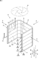
室外熱交換器14は、内部を流れる冷媒と空気との間で熱交換を行わせる機器である。本実施形態の室外熱交換器14は、上面視において略U字形状に形成されている。この室外熱交換器14は、例えば、直方体形状に形成された室外機2のケーシングに収容され、当該ケーシングの3つの側壁に対向するように配置される。本実施形態の室外熱交換器14は、一対のヘッダ21,22と、熱交換器本体23とを有する。一対のヘッダ21,22及び熱交換器本体23は、アルミニウム製又はアルミニウム合金製である。
The
一対のヘッダ21,22は、熱交換器本体23の両端に配置されている。一方のヘッダ21は、液状冷媒(気液二相冷媒)が流れる液ヘッダである。他方のヘッダ22は、ガス状冷媒が流れるガスヘッダである。液ヘッダ21及びガスヘッダ22は、その長手方向を上下方向Zに向けた状態で配置されている。液ヘッダ21には、前述したキャピラリ管37A〜37Fを有する冷媒分流器19が接続されている。ガスヘッダ22には、ガス配管24が接続されている。
The pair of
熱交換器本体23は、内部を流れる冷媒と空気との間で熱交換を行う部分である。空気は、矢印aで示すように、略U字形状に形成された熱交換器本体23の外側から内側へ熱交換器本体23と交差する方向に通過する。
The heat exchanger
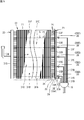
図3に示すように、熱交換器本体23は、複数の伝熱管26と、複数のフィン27とを有する。複数の伝熱管26は、水平に配置されている。複数の伝熱管26は、ヘッダ21,22の長手方向である上下方向に並べて配置されている。各伝熱管26の長手方向の一端部は液ヘッダ21に接続されている。各伝熱管26の長手方向の他端部は、ガスヘッダ22に接続されている。
As shown in FIG. 3, the heat exchanger
図4に示すように、本実施形態の伝熱管26は、複数の冷媒の流路30A,30Bが形成された多穴管である。各流路30A,30Bは、伝熱管26の長手方向に沿って延びている。冷媒は、伝熱管26の各流路30A,30Bを流れている間に空気と熱交換する。複数の流路30A,30Bは、熱交換器本体23に対する空気の流れ方向aに沿って並べて配置されている。空気は、複数の伝熱管26の上下方向の間を通過する。伝熱管26は、複数の流路30A,30Bが並ぶ方向(空気の流れ方向a)の長さよりも上下方向の長さの方が小さい扁平形状に形成されている。複数の流路30A,30Bが並ぶ方向における伝熱管26の両端面26aは、半円弧状に形成されている。
As shown in FIG. 4, the
複数のフィン27は、伝熱管26の長手方向に沿って並べて配置されている。各フィン27は、上下方向に長く形成された薄板材である。フィン27には、空気の流れ方向aの一方側の辺27cから他方側の辺に向けて延びる溝27aが、上下方向に間隔をあけて複数個並べて形成されている。溝27aは、フィン27の一方側の辺27cにおいて開放されている。伝熱管26は、フィン27の各溝27aに挿入された状態でフィン27に取り付けられている。フィン27には、熱伝達を促進するためのルーバー27bと、補強用のリブ27dとが形成されている。
The plurality of
図2及び図3に例示する熱交換器本体23は、複数の熱交換部31A〜31Fを有している。複数の熱交換部31A〜31Fは、上下方向に並べて配置されている。液ヘッダ21の内部は、熱交換部31A〜31Fごとに上下に区画されている。言い換えると、図3に示すように、液ヘッダ21の内部には、熱交換部31A〜31Fごとの流路33A〜33Fが形成されている。
The heat exchanger
液ヘッダ21には、複数の接続管35A〜35Fが接続されている。各接続管35A〜35Fは、各流路33A〜33Fに対応して設けられている。各接続管35A〜35Fには、冷媒分流器19のキャピラリ管37A〜37Fが接続されている。
暖房運転の際に、冷媒分流器19で分流された液状冷媒は、キャピラリ管37A〜37F及び接続管35A〜35Fを流れて液ヘッダ21内の各流路33A〜33Fに流入し、各流路33A〜33Fに接続された1又は複数の伝熱管26を通ってガスヘッダ22へ流れる。逆に、冷房運転又は除霜運転の際に、ガスヘッダ22で各伝熱管26に分流された冷媒は、液ヘッダ21の各流路33A〜33Fに流入し、各流路33A〜33Fから各キャピラリ管37A〜37Fを流れて冷媒分流器19で合流する。
A plurality of connecting
During the heating operation, the liquid refrigerant separated by the
ガスヘッダ22の内部は区画されておらず、全ての熱交換部31A〜31Fにわたって連続している。したがって、1本のガス配管24からガスヘッダ22に流入した冷媒は、全ての伝熱管26に分流され、全ての伝熱管26からガスヘッダ22に流入した冷媒は、ガスヘッダ22で合流されて1本のガス配管24に流入する。
The inside of the
[伝熱管の具体的構造]
図5は、伝熱管の断面図である。図6は、伝熱管の第1流路を拡大して示す断面図である。図7は、伝熱管の第2流路を拡大して示す断面図である。
図5に示すように、伝熱管26には、複数の流路30A,30Bが形成されている。伝熱管26の空気流方向aの両端には、第2流路30Bが形成されている。2個の第2流路30Bの間には、複数の第1流路30Aが並べて形成されている。本実施形態では、7個の第1流路30Aと2個の第2流路30Bとが空気流方向aに一列に並べて形成されている。以下の説明においては、流路30A,30Bの並び方向を「第1方向P」ともいう。
[Specific structure of heat transfer tube]
FIG. 5 is a cross-sectional view of the heat transfer tube. FIG. 6 is an enlarged cross-sectional view showing the first flow path of the heat transfer tube. FIG. 7 is an enlarged cross-sectional view showing the second flow path of the heat transfer tube.
As shown in FIG. 5, a plurality of
図6に示すように、第1流路30Aは、第1方向Pに長い長方形の断面形状を有する。図6には、第1流路30Aの断面形状における長辺の長さ(第1方向Pの長さ)がL1a,短辺の長さ(上下方向の長さ)がL1bで示されている。第1流路30Aの内面には、複数の突起31が形成されている。具体的に、複数の突起31は、第1流路30Aの断面形状における2つの長辺側の内面に形成されている。図6に示す例では、各内面に6個の突起31が形成されている。各突起31は、第1方向Pの長さが先端側ほど小さくなるような先細り形状に形成されている。
As shown in FIG. 6, the
図7に示すように、第2流路30Bは、第1方向Pに長い長方形の断面形状を有する。図7には、第2流路30Bの断面形状における長辺の長さがL2a、短辺の長さがL2bで示されている。第2流路30Bの長辺の長さL2aは、第1流路30Aの長辺の長さL1aよりも短い。第2流路30Bの短辺の長さL2bは、第1流路30Aの短辺の長さL1bと同じである。第2流路30Bの断面積は、第1流路30Aの断面積よりも小さい。
As shown in FIG. 7, the
第2流路30Bの内面には、複数の突起31が形成されている。具体的に、複数の突起31は、第2流路30Bの断面形状における2つの長辺側の内面に形成されている。図7に示す例では、各内面に4個の突起31が形成されている。第2流路30Bの突起31と、第1流路30Aの突起31とは、同一の形状である。第2流路30Bの長辺の長さL2aは、第1流路30Aの長辺の長さL1aよりも短いので、第2流路30Bに形成することができる突起31の数は、第1流路30Aに形成することができる突起31の数よりも少なくなっている。
A plurality of
以上のように第1、第2流路30A,30Bの内面に突起31が形成されることによって各流路の表面積が増大するため、熱交換効率を向上させることができる。
As described above, the surface area of each flow path is increased by forming the
(第1流路30Aの形状について)
第1流路30Aは、断面形状が長方形であり、この長方形の長辺側の長さL1aと、短辺側の長さL1bとの比率であるアスペクト比は、1.1以上1.5以下に設定されている。アスペクト比をこのような値に設定した理由は、次の(1)〜(4)の事項を考慮したことによる。
(About the shape of the
The
(1) 図4に示すように、伝熱管26内の第1流路30A(以下、単に「流路」ともいう)の並び方向に沿って空気が流れると、空気流方向aの上流側(図4の右側)では、流路30A内の冷媒と空気との温度差が大きいため、効率よく熱交換が行われる。一方、空気流方向aの下流側(図4の左側)には、上流側で熱交換された空気が流れてくるため、流路30A内の冷媒と空気との温度差が小さくなる。よって、上流側に比べて熱交換効率が低下する。空気流方向aの上流側の流路30Aを流れる冷媒と、空気流方向aの下流側の流路30Aを流れる冷媒とでは、状態変化するタイミングが異なる。そのため、室外熱交換器14は、下流側の流路30A内の冷媒が適切に状態変化するように設計される。しかし、上流側の流路30Aと下流側の流路30Aとで熱交換効率が大きく異なると、上流側の流路30Aでは、状態変化し終わった冷媒を室外熱交換器14内に流すことになり、能力に無駄が生じてしまう。この現象を抑制するには、流路30Aの総断面積を減らすことなく伝熱管26内の流路30Aの数を少なくすればよいため、流路30Aの断面形状を空気流方向aに長い長方形に形成することが有効である。
(1) As shown in FIG. 4, when air flows along the arrangement direction of the
(2) 上記(1)の考えに基づいて流路30Aの断面形状を長方形とした場合、その長辺を長くするほど(アスペクト比を大きくするほど)、流路30Aの長辺側の内面に多くの突起31を形成することができる。そのため、流路30A内の表面積を大きくすることができ、熱交換効率の向上を期待することができる。
(2) When the cross-sectional shape of the
(3)しかし、流路30Aの断面形状の長辺を長くするほど、伝熱管26内の流路30Aの数が少なくなると同時に流路30Aと流路30Aとを仕切る壁26b(図5参照)の数も少なくなるため、伝熱管26の強度が低下する。そのため、伝熱管26の強度低下を防ぐために壁26bの厚みt1を大きくする必要がある。その結果、流路30Aの断面形状の長辺を長くしても、これに比例して流路30Aの表面積を大きくすることができない。
(3) However, as the long side of the cross-sectional shape of the
(4)さらに、流路30Aの断面形状の長辺を長くするほど、各流路30Aにおける冷媒の流速が低下するため、個々の流路(単一の流路)30Aにおける熱交換性能が低下する可能性がある。また、流路30Aの断面形状の長辺が長くなると、流路30Aの内面のうち、長辺の中心位置付近では冷媒と流路30Aの内面とが接触しない領域が発生し、その内面の冷媒と接触しない領域では冷媒との熱交換ができないため熱交換効率が低下する。
(4) Further, as the long side of the cross-sectional shape of the
図9は、アスペクト比と、流路内の表面積及び単一流路の熱交換性能比との関係を示すグラフである。図9を参照すると、流路のアスペクト比が大きくなるほど流路内の表面積は大きくなるが、アスペクト比が大きくなるほど、個々の流路の熱交換性能比は低下していることがわかる。 FIG. 9 is a graph showing the relationship between the aspect ratio, the surface area in the flow path, and the heat exchange performance ratio of the single flow path. With reference to FIG. 9, it can be seen that the larger the aspect ratio of the flow path, the larger the surface area in the flow path, but the larger the aspect ratio, the lower the heat exchange performance ratio of each flow path.
本出願の発明者は、上記(1)〜(4)の事項及び図9に示す関係に鑑み、次の表1に示すような条件A〜Fで、流路のアスペクト比と伝熱管26の熱交換性能との関係を求めた。
In view of the above items (1) to (4) and the relationship shown in FIG. 9, the inventor of the present application considers the aspect ratio of the flow path and the

表1においては、伝熱管26の上下方向の長さ(厚み)と第1方向Pの長さとを一定にした状態で、A〜Fの6つの条件で流路の数を変化させ、流路の数に応じた壁の厚みとアスペクト比と突起の数(溝の数)とを設定し、熱交換性能比を求めた。熱交換性能比は、条件Aを100%としたときの比率とした。伝熱管26の上下方向の長さは、2.0mm、第1方向Pの長さは、22.2mmである。
In Table 1, the number of flow paths is changed under the six conditions A to F while the length (thickness) of the
図8は、表1に示す流路のアスペクト比と熱交換性能比との関係を示すグラフである。
図8に示すように、熱交換性能比は、アスペクト比が0.7から1.3までの間で上昇するが、それ以降は、低下している。これは、アスペクト比が1.3を超えると、流路内の表面積の増加よりも流路間の壁の厚みの増大及び各流路の個々の性能低下の影響が大きいからであると考えられる。本実施形態の伝熱管26においては、表1及び図8の結果より、適切な熱交換性能を得ることができるアスペクト比として1.1以上1.5以下の値を採用し、第1流路30Aの断面形状における長辺及び短辺の長さLa1、La2を設定している。
FIG. 8 is a graph showing the relationship between the aspect ratio of the flow path shown in Table 1 and the heat exchange performance ratio.
As shown in FIG. 8, the heat exchange performance ratio increases in the aspect ratio between 0.7 and 1.3, but decreases thereafter. It is considered that this is because when the aspect ratio exceeds 1.3, the influence of the increase in the wall thickness between the flow paths and the individual performance deterioration of each flow path is larger than the increase in the surface area in the flow path. .. In the
なお、第1流路30Aと第1流路30Aとの間の距離(壁26bの厚み)t1は、0.5mm以上0.6mm以下とすることが好適である。
The distance (thickness of the
(第2流路30B及び伝熱管26の端面26aの形状について)
図5及び図7に示すように、室外熱交換器14を蒸発器として使用するとき、伝熱管26内には冷却された冷媒が通過するため、伝熱管26の表面の温度も下がり、着霜することがある。特に、図4に示すように、室外熱交換器14の伝熱管26の第1方向Pの一方側の端面26a(右側の端面)は、フィン27と接触していないため、冷媒により冷却された伝熱管26の端面26aからフィン27に伝熱することができない。そのため、フィン27が接触していない伝熱管26の端面26aにおいて伝熱管26の温度低下が著しくなり、より着霜が生じやすくなる。フィン27が接触していない伝熱管26の端面26aは、空気流方向aの上流側に位置しているので、水分を含む空気が接触し、より着霜が生じやすくなる。
(Regarding the shape of the
As shown in FIGS. 5 and 7, when the
本実施形態では、第1方向Pにおける伝熱管26の内部の両端部に、第2流路30Bが形成されている。この第2流路30Bの断面積は、第1流路30Aの断面積よりも小さい。したがって、第2流路30Bを流れる冷媒量は、第1流路30Aを流れる冷媒量よりも少なくなり、伝熱管26の端面26aへの伝熱量が低下する。そのため、伝熱管26の内部における第1方向Pの端部に第2流路30Bを形成することで、伝熱管26の端面26aにおける着霜を抑制することができる。本実施形態における第2流路30Bのアスペクト比は、第1流路30Aのアスペクト比である1.1以上1.5以下の範囲内には含まれておらず、1.1未満とされている。
In the present embodiment, the
図5及び図7に示すように、第2流路30Bと、第2流路30Bに最も近い第1方向Pにおける伝熱管26の端面26aとの間の第1方向Pの最大距離(伝熱管26の端部の厚み)t2は、第1流路30Aと第1流路30Aとの間の第1方向Pの距離(壁26bの厚み)t1よりも大きい。そのため、第2流路30Bを流れる冷媒の熱は、伝熱管26の端面26aに伝わりにくくなっており、着霜をより抑制することができる。第1流路30Aと第2流路30Bとの間の距離(壁26bの厚み)t1も、第1流路30A間の距離t1と同じである。
As shown in FIGS. 5 and 7, the maximum distance (heat transfer tube) of the first direction P between the
図7に示すように、フィン27に形成された溝27aは、伝熱管26の上下方向の長さと略同一の上下方向の長さL3を有する第1部分27a1と、フィン27の第1方向Pの一端側において、第1部分27a1よりも上下方向の長さが拡大された第2部分27a2とを有している。図7には、第2部分27a2の上下方向の最大長さをL4で示し、第2部分27a2の第1方向Pの範囲をWで示している。
As shown in FIG. 7, the
伝熱管26の端面26aは、断面形状が半円弧状に形成されている。伝熱管26の端面26aは、一部が溝27aの第1部分27a1内に配置され、残りの部分が、溝27aの第2部分27a2の第1方向Pの範囲W内に配置されている。伝熱管26の端面26aと溝27aの第1部分27a1とは、隙間Sをあけて接近している。
The
伝熱管26の端面26aの半径は、約1.0mmであり、第2部分27a2に配置された伝熱管26の端面26aの第1方向Pの長さL5は、例えば0.20〜0.24mmであり、より好ましくは、0.22mmである。
The radius of the
[他の実施形態]
第1流路30A及び第2流路30Bに形成された突起31は、第1流路30A及び第2流路30Bの断面形状における短辺側の内面に形成されていてもよいし、長辺側の内面及び短辺側の内面の双方に形成されていてもよい。
上記実施形態では、第2流路30Bの断面形状が長方形状であったが、正方形又は円形状等の他の形状であってもよい。
[Other Embodiments]
The
In the above embodiment, the cross-sectional shape of the
上記実施形態では、伝熱管26の第1方向Pの端面26aは、半円弧状に形成されていたが、上下方向に沿った平坦面であってもよい。
In the above embodiment, the
[実施形態の作用効果]
(1)上記実施形態の伝熱管26は、内部に、複数の第1流路30Aが並べて形成され、各第1流路30Aの断面形状が、複数の第1流路30Aの並び方向である第1方向Pに長い長方形であり、第1流路30Aの内面に複数の突起31が形成され、第1流路30Aの断面形状における長辺の長さL1aと短辺の長さL1bとの比率が、1.1以上1.5以下である。これにより、第1流路30Aの断面形状における長辺と短辺との長さの比率を適切に設定し、熱交換性能を向上させることができる。
[Action and effect of the embodiment]
(1) The
(3)上記実施形態では、伝熱管26の内部における第1方向Pの端部には、第2流路30Bが形成され、第2流路30Bの断面積が、第1流路30Aの断面積よりも小さい。第1方向Pにおける伝熱管26の端部では、着霜が生じやすいため、第2流路30Bの断面積を第1流路30Aの断面積よりも小さくし、第2流路30Bを流れる冷媒の流量を少なくすることによって着霜を抑制することができる。
(3) In the above embodiment, the
(4)上記実施形態では、伝熱管26の内部における第1方向Pの両端部に、第2流路30Bが形成されている。そのため、伝熱管26の第1方向Pの両端部における着霜を抑制することができる。
(4) In the above embodiment, the
(5)上記実施形態では、第2流路30Bと、この第2流路30Bに最も近い第1方向Pにおける伝熱管26の端面26aとの間の第1方向Pの最大距離t2が、隣接する2つの第1流路30Aの間の第1方向Pの距離t1よりも大きい。第1方向Pにおける伝熱管26の端面26aでは、着霜が生じやすいため、第2流路30Bと伝熱管26の端面26aとの最大距離t2を、隣接する第1流路30A間の距離t1よりも長くすることによって、第2流路30Bを流れる冷媒の熱が、伝熱管26の端面26aに伝わりにくくなり、着霜を抑制することができる。
(5) In the above embodiment, the maximum distance t2 of the first direction P between the
(6)上記実施形態の室外熱交換器14は、ヘッダ21,22と、ヘッダ21,22の長手方向に並べて配置され、ヘッダ21,22に端部が接続される複数の伝熱管26と、伝熱管26の外周面に接触するフィン27と、を備え、フィン27が、第1方向Pにおける伝熱管26の一方側の端面26aを除いて、伝熱管26の外周面に接触しており、伝熱管26の内部における前記一方側に、第2流路30Bが形成されている。フィン27が接触していない伝熱管26の一方側の端面26aは、フィン27が接触している他の部分よりも低温となり、着霜しやすくなるため、伝熱管26内の前記一方側の端部に第2流路30Bを形成することで、冷媒流量を少なくし、着霜を抑制することができる。
(6) The
21:液ヘッダ
22:ガスヘッダ
26:伝熱管
26a:端面
27:フィン
30A:第1流路
30B:第2流路
31:突起
21: Liquid header 22: Gas header 26:
(6) 本開示の熱交換器は、
ヘッダと、
ヘッダの長手方向に並べて配置され、前記ヘッダに端部が接続される上記(1)〜(5)のいずれか1つに記載の複数の伝熱管と、を備えている。
(6) The heat exchanger of the present disclosure is
Header and
The plurality of heat transfer tubes according to any one of (1) to (5 ) above, which are arranged side by side in the longitudinal direction of the header and whose ends are connected to the header, are provided.
(7) 本開示の熱交換器は、
ヘッダと、
前記ヘッダの長手方向に並べて配置され、前記ヘッダに端部が接続される上記の(3)〜(5)のいずれか1つに記載の複数の伝熱管と、
フィンと、を備え、
前記フィンが、前記第1方向における前記伝熱管の一方側の端面を除いて、前記伝熱管の外周面に接触しており、
前記伝熱管の内部における前記一方側の端部に、前記第2流路が形成されている。
(7) The heat exchanger of the present disclosure is
Header and
The plurality of heat transfer tubes according to any one of (3 ) to ( 5 ) above, which are arranged side by side in the longitudinal direction of the header and whose ends are connected to the header.
With fins,
The fins are in contact with the outer peripheral surface of the heat transfer tube except for one end surface of the heat transfer tube in the first direction.
The second flow path is formed at one end of the heat transfer tube on one side.
(1)本開示の伝熱管は、
内部に、複数の第1流路が並べて形成され、
前記各第1流路の断面形状が、複数の前記第1流路の並び方向である第1方向に長い長方形であり、
前記第1流路の内面に複数の突起が形成され、
前記第1流路の断面形状における長辺の長さと短辺の長さとの比率が、1.1以上1.5以下であり、
前記第1流路の断面形状における長辺の長さに対する、隣接する前記第1流路の間の距離の比率が、29%〜33%である。
(1) The heat transfer tube of the present disclosure is
A plurality of first flow paths are formed side by side inside.
The cross-sectional shape of each of the first flow paths is a rectangle long in the first direction, which is the arrangement direction of the plurality of first flow paths.
A plurality of protrusions are formed on the inner surface of the first flow path,
The ratio of the length of the short side of the long sides of the cross-sectional shape of the first flow path state, and are 1.1 to 1.5,
To the length of the long sides of the cross-sectional shape of the first flow path, the ratio of the distance between the first flow path adjacent, Ru 29% to 33% der.
Claims (7)
前記各第1流路(30A)の断面形状が、複数の前記第1流路(30A)の並び方向である第1方向(P)に長い長方形であり、
前記第1流路(30A)の内面に複数の突起(31)が形成され、
前記第1流路(30A)の断面形状における長辺の長さ(L1a)と短辺の長さ(L1b)との比率が、1.1以上1.5以下である、伝熱管。 A plurality of first flow paths (30A) are formed side by side inside.
The cross-sectional shape of each of the first flow paths (30A) is a rectangle long in the first direction (P), which is the arrangement direction of the plurality of first flow paths (30A).
A plurality of protrusions (31) are formed on the inner surface of the first flow path (30A).
A heat transfer tube in which the ratio of the length of the long side (L1a) to the length of the short side (L1b) in the cross-sectional shape of the first flow path (30A) is 1.1 or more and 1.5 or less.
前記第2流路(30B)の断面積が、前記第1流路(30A)の断面積よりも小さい、請求項1又は2に記載の伝熱管。 A second flow path (30B) is formed at the end of the first direction (P) inside the heat transfer tube.
The heat transfer tube according to claim 1 or 2, wherein the cross-sectional area of the second flow path (30B) is smaller than the cross-sectional area of the first flow path (30A).
前記ヘッダ(21,22)の長手方向に並べて配置され、前記ヘッダ(21,22)に端部が接続される請求項1〜4のいずれか1項に記載の複数の伝熱管と、を備えている、熱交換器。 Header (21,22) and
The plurality of heat transfer tubes according to any one of claims 1 to 4, which are arranged side by side in the longitudinal direction of the headers (21,22) and whose ends are connected to the headers (21,22). The heat exchanger.
前記ヘッダ(21,22)の長手方向に並べて配置され、前記ヘッダ(21,22)に端部が接続される請求項2〜4のいずれか1項に記載の複数の伝熱管と、
フィン(27)と、を備え、
前記フィン(27)が、前記第1方向(P)における前記伝熱管(26)の一方側の端面(26a)を除いて、前記伝熱管(26)の外周面に接触しており、
前記伝熱管(26)の内部における前記一方側の端部に、前記第2流路(30B)が形成されている、熱交換器。
Header (21,22) and
The plurality of heat transfer tubes according to any one of claims 2 to 4, which are arranged side by side in the longitudinal direction of the headers (21,22) and whose ends are connected to the headers (21,22).
With fins (27),
The fins (27) are in contact with the outer peripheral surface of the heat transfer tube (26) except for one end surface (26a) of the heat transfer tube (26) in the first direction (P).
A heat exchanger in which the second flow path (30B) is formed at one end of the heat transfer tube (26) on one side.
Priority Applications (6)
| Application Number | Priority Date | Filing Date | Title |
|---|---|---|---|
| JP2019205903A JP2021081081A (en) | 2019-11-14 | 2019-11-14 | Heat transfer pipe and heat exchanger |
| PCT/JP2020/040840 WO2021095567A1 (en) | 2019-11-14 | 2020-10-30 | Heat transfer pipe and heat exchanger |
| CN202080079251.7A CN114729793B (en) | 2019-11-14 | 2020-10-30 | Heat transfer tube and heat exchanger |
| EP20887565.8A EP4060252B1 (en) | 2019-11-14 | 2020-10-30 | Heat transfer pipe and heat exchanger |
| JP2021147510A JP7381909B2 (en) | 2019-11-14 | 2021-09-10 | Heat exchanger tubes and heat exchangers |
| US17/743,141 US20220268525A1 (en) | 2019-11-14 | 2022-05-12 | Heat transfer tube and heat exchanger |
Applications Claiming Priority (1)
| Application Number | Priority Date | Filing Date | Title |
|---|---|---|---|
| JP2019205903A JP2021081081A (en) | 2019-11-14 | 2019-11-14 | Heat transfer pipe and heat exchanger |
Related Child Applications (1)
| Application Number | Title | Priority Date | Filing Date |
|---|---|---|---|
| JP2021147510A Division JP7381909B2 (en) | 2019-11-14 | 2021-09-10 | Heat exchanger tubes and heat exchangers |
Publications (1)
| Publication Number | Publication Date |
|---|---|
| JP2021081081A true JP2021081081A (en) | 2021-05-27 |
Family
ID=75912335
Family Applications (2)
| Application Number | Title | Priority Date | Filing Date |
|---|---|---|---|
| JP2019205903A Pending JP2021081081A (en) | 2019-11-14 | 2019-11-14 | Heat transfer pipe and heat exchanger |
| JP2021147510A Active JP7381909B2 (en) | 2019-11-14 | 2021-09-10 | Heat exchanger tubes and heat exchangers |
Family Applications After (1)
| Application Number | Title | Priority Date | Filing Date |
|---|---|---|---|
| JP2021147510A Active JP7381909B2 (en) | 2019-11-14 | 2021-09-10 | Heat exchanger tubes and heat exchangers |
Country Status (5)
| Country | Link |
|---|---|
| US (1) | US20220268525A1 (en) |
| EP (1) | EP4060252B1 (en) |
| JP (2) | JP2021081081A (en) |
| CN (1) | CN114729793B (en) |
| WO (1) | WO2021095567A1 (en) |
Families Citing this family (1)
| Publication number | Priority date | Publication date | Assignee | Title |
|---|---|---|---|---|
| KR20200078936A (en) * | 2018-12-24 | 2020-07-02 | 삼성전자주식회사 | Heat exchanger |
Citations (16)
| Publication number | Priority date | Publication date | Assignee | Title |
|---|---|---|---|---|
| JPS5913877U (en) * | 1982-07-13 | 1984-01-27 | 株式会社デンソー | Heat exchanger |
| JPH02166393A (en) * | 1988-12-16 | 1990-06-27 | Matsushita Refrig Co Ltd | Heat exchanger with fin |
| JPH06185885A (en) * | 1992-07-24 | 1994-07-08 | Furukawa Electric Co Ltd:The | Flat multi-holed condensing and heat transfer pipe |
| JPH06300473A (en) * | 1993-04-19 | 1994-10-28 | Sanden Corp | Flat refrigerant pipe |
| JP2000018867A (en) * | 1998-06-23 | 2000-01-18 | Mitsubishi Heavy Ind Ltd | Tube material for heat exchanger and heat exchanger |
| JP2000154987A (en) * | 1998-11-19 | 2000-06-06 | Daikin Ind Ltd | Air heat exchanger |
| JP2000329487A (en) * | 1999-05-21 | 2000-11-30 | Bosch Automotive Systems Corp | Heat exchanger |
| JP2002318086A (en) * | 2001-04-16 | 2002-10-31 | Japan Climate Systems Corp | Heat exchanger tube |
| JP2005090760A (en) * | 2003-09-12 | 2005-04-07 | Matsushita Electric Ind Co Ltd | Heat exchanger |
| JP2006162085A (en) * | 2004-12-02 | 2006-06-22 | Matsushita Electric Ind Co Ltd | Flat tube for heat exchanger |
| JP2009063228A (en) * | 2007-09-06 | 2009-03-26 | Showa Denko Kk | Flat heat transfer tube |
| JP2013019596A (en) * | 2011-07-11 | 2013-01-31 | Mitsubishi Electric Corp | Heat exchanger, indoor unit, and outdoor unit |
| WO2016103437A1 (en) * | 2014-12-26 | 2016-06-30 | 三菱電機株式会社 | Refrigeration cycle apparatus |
| WO2017073715A1 (en) * | 2015-10-29 | 2017-05-04 | 株式会社Uacj | Aluminum extruded flat perforated tube and heat exchanger |
| WO2017141943A1 (en) * | 2016-02-15 | 2017-08-24 | 株式会社Uacj | Heat exchanger |
| WO2018008134A1 (en) * | 2016-07-07 | 2018-01-11 | 三菱電機株式会社 | Heat exchanger |
Family Cites Families (5)
| Publication number | Priority date | Publication date | Assignee | Title |
|---|---|---|---|---|
| JPH1144498A (en) * | 1997-05-30 | 1999-02-16 | Showa Alum Corp | Flat porous tube for heat exchanger and heat exchanger using the tube |
| JP4328512B2 (en) | 2001-10-23 | 2009-09-09 | 昭和電工株式会社 | Die for extruding fine multi-hole tube, mandrel used for the die, and multi-hole tube manufactured using the die |
| JP2013024472A (en) | 2011-07-20 | 2013-02-04 | Daikin Industries Ltd | Flat tube for heat exchanger |
| JP2014001868A (en) | 2012-06-15 | 2014-01-09 | Sanden Corp | Heat exchanger |
| JP2019011923A (en) | 2017-06-30 | 2019-01-24 | ダイキン工業株式会社 | Heat exchanger |
-
2019
- 2019-11-14 JP JP2019205903A patent/JP2021081081A/en active Pending
-
2020
- 2020-10-30 CN CN202080079251.7A patent/CN114729793B/en active Active
- 2020-10-30 WO PCT/JP2020/040840 patent/WO2021095567A1/en unknown
- 2020-10-30 EP EP20887565.8A patent/EP4060252B1/en active Active
-
2021
- 2021-09-10 JP JP2021147510A patent/JP7381909B2/en active Active
-
2022
- 2022-05-12 US US17/743,141 patent/US20220268525A1/en active Pending
Patent Citations (16)
| Publication number | Priority date | Publication date | Assignee | Title |
|---|---|---|---|---|
| JPS5913877U (en) * | 1982-07-13 | 1984-01-27 | 株式会社デンソー | Heat exchanger |
| JPH02166393A (en) * | 1988-12-16 | 1990-06-27 | Matsushita Refrig Co Ltd | Heat exchanger with fin |
| JPH06185885A (en) * | 1992-07-24 | 1994-07-08 | Furukawa Electric Co Ltd:The | Flat multi-holed condensing and heat transfer pipe |
| JPH06300473A (en) * | 1993-04-19 | 1994-10-28 | Sanden Corp | Flat refrigerant pipe |
| JP2000018867A (en) * | 1998-06-23 | 2000-01-18 | Mitsubishi Heavy Ind Ltd | Tube material for heat exchanger and heat exchanger |
| JP2000154987A (en) * | 1998-11-19 | 2000-06-06 | Daikin Ind Ltd | Air heat exchanger |
| JP2000329487A (en) * | 1999-05-21 | 2000-11-30 | Bosch Automotive Systems Corp | Heat exchanger |
| JP2002318086A (en) * | 2001-04-16 | 2002-10-31 | Japan Climate Systems Corp | Heat exchanger tube |
| JP2005090760A (en) * | 2003-09-12 | 2005-04-07 | Matsushita Electric Ind Co Ltd | Heat exchanger |
| JP2006162085A (en) * | 2004-12-02 | 2006-06-22 | Matsushita Electric Ind Co Ltd | Flat tube for heat exchanger |
| JP2009063228A (en) * | 2007-09-06 | 2009-03-26 | Showa Denko Kk | Flat heat transfer tube |
| JP2013019596A (en) * | 2011-07-11 | 2013-01-31 | Mitsubishi Electric Corp | Heat exchanger, indoor unit, and outdoor unit |
| WO2016103437A1 (en) * | 2014-12-26 | 2016-06-30 | 三菱電機株式会社 | Refrigeration cycle apparatus |
| WO2017073715A1 (en) * | 2015-10-29 | 2017-05-04 | 株式会社Uacj | Aluminum extruded flat perforated tube and heat exchanger |
| WO2017141943A1 (en) * | 2016-02-15 | 2017-08-24 | 株式会社Uacj | Heat exchanger |
| WO2018008134A1 (en) * | 2016-07-07 | 2018-01-11 | 三菱電機株式会社 | Heat exchanger |
Also Published As
| Publication number | Publication date |
|---|---|
| JP2021191996A (en) | 2021-12-16 |
| US20220268525A1 (en) | 2022-08-25 |
| WO2021095567A1 (en) | 2021-05-20 |
| EP4060252A4 (en) | 2022-12-07 |
| JP7381909B2 (en) | 2023-11-16 |
| CN114729793A (en) | 2022-07-08 |
| EP4060252A1 (en) | 2022-09-21 |
| CN114729793B (en) | 2024-04-02 |
| EP4060252B1 (en) | 2023-09-13 |
Similar Documents
| Publication | Publication Date | Title |
|---|---|---|
| US9651317B2 (en) | Heat exchanger and air conditioner | |
| JP6180338B2 (en) | Air conditioner | |
| US10309701B2 (en) | Heat exchanger and air conditioner | |
| EP2868999A2 (en) | Refrigeration cycle of refrigerator | |
| US20140102131A1 (en) | Outdoor unit of refrigeration system | |
| WO2014181400A1 (en) | Heat exchanger and refrigeration cycle device | |
| US11009300B2 (en) | Heat exchanger and air-conditioning apparatus | |
| US10480869B2 (en) | Heat exchanger and refrigeration cycle apparatus including the same | |
| CN114641663A (en) | Heat exchanger and refrigeration cycle device | |
| JP6351875B1 (en) | Heat exchanger and refrigeration cycle apparatus | |
| JP7381909B2 (en) | Heat exchanger tubes and heat exchangers | |
| US20230101157A1 (en) | Heat exchanger and air-conditioning apparatus | |
| US20230168040A1 (en) | Heat exchanger, outdoor unit including heat exchanger, and air-conditioning apparatus including outdoor unit | |
| JP5646257B2 (en) | Refrigeration cycle equipment | |
| US20220268497A1 (en) | Heat exchanger | |
| EP3699538B1 (en) | Heat exchanger and refrigeration cycle device | |
| JP7414845B2 (en) | Refrigeration cycle equipment | |
| JP2017203620A (en) | Air conditioner | |
| JP2014137172A (en) | Heat exchanger and refrigerator | |
| JP4983878B2 (en) | Heat exchanger, refrigerator equipped with this heat exchanger, and air conditioner | |
| JPWO2020178966A1 (en) | Gas header, heat exchanger and refrigeration cycle equipment | |
| JP6415597B2 (en) | Refrigeration cycle equipment | |
| JP7258151B2 (en) | Heat exchanger and refrigeration cycle equipment | |
| WO2023281655A1 (en) | Heat exchanger and refrigeration cycle device | |
| CN115103987A (en) | Heat exchanger for heat source side unit and heat pump device provided with same |
Legal Events
| Date | Code | Title | Description |
|---|---|---|---|
| A521 | Request for written amendment filed |
Free format text: JAPANESE INTERMEDIATE CODE: A523 Effective date: 20201030 |
|
| A621 | Written request for application examination |
Free format text: JAPANESE INTERMEDIATE CODE: A621 Effective date: 20201030 |
|
| A131 | Notification of reasons for refusal |
Free format text: JAPANESE INTERMEDIATE CODE: A131 Effective date: 20201117 |
|
| A521 | Request for written amendment filed |
Free format text: JAPANESE INTERMEDIATE CODE: A523 Effective date: 20210114 |
|
| A02 | Decision of refusal |
Free format text: JAPANESE INTERMEDIATE CODE: A02 Effective date: 20210615 |
|
| C60 | Trial request (containing other claim documents, opposition documents) |
Free format text: JAPANESE INTERMEDIATE CODE: C60 Effective date: 20210910 |
|
| C22 | Notice of designation (change) of administrative judge |
Free format text: JAPANESE INTERMEDIATE CODE: C22 Effective date: 20211214 |
|
| C22 | Notice of designation (change) of administrative judge |
Free format text: JAPANESE INTERMEDIATE CODE: C22 Effective date: 20220412 |
|
| C23 | Notice of termination of proceedings |
Free format text: JAPANESE INTERMEDIATE CODE: C23 Effective date: 20220524 |
|
| C03 | Trial/appeal decision taken |
Free format text: JAPANESE INTERMEDIATE CODE: C03 Effective date: 20220621 |
|
| C30A | Notification sent |
Free format text: JAPANESE INTERMEDIATE CODE: C3012 Effective date: 20220621 |