EP4060252B1 - Heat transfer pipe and heat exchanger - Google Patents
Heat transfer pipe and heat exchanger Download PDFInfo
- Publication number
- EP4060252B1 EP4060252B1 EP20887565.8A EP20887565A EP4060252B1 EP 4060252 B1 EP4060252 B1 EP 4060252B1 EP 20887565 A EP20887565 A EP 20887565A EP 4060252 B1 EP4060252 B1 EP 4060252B1
- Authority
- EP
- European Patent Office
- Prior art keywords
- heat transfer
- flow path
- transfer tube
- flow paths
- flow
- Prior art date
- Legal status (The legal status is an assumption and is not a legal conclusion. Google has not performed a legal analysis and makes no representation as to the accuracy of the status listed.)
- Active
Links
- 239000003507 refrigerant Substances 0.000 description 65
- 239000007788 liquid Substances 0.000 description 16
- 230000005764 inhibitory process Effects 0.000 description 9
- 230000007423 decrease Effects 0.000 description 8
- 238000011144 upstream manufacturing Methods 0.000 description 8
- 230000006872 improvement Effects 0.000 description 5
- 238000001816 cooling Methods 0.000 description 4
- 238000010438 heat treatment Methods 0.000 description 4
- 230000006866 deterioration Effects 0.000 description 3
- 230000014509 gene expression Effects 0.000 description 3
- 239000000314 lubricant Substances 0.000 description 3
- 230000008859 change Effects 0.000 description 2
- 238000010586 diagram Methods 0.000 description 2
- 230000009467 reduction Effects 0.000 description 2
- 238000005057 refrigeration Methods 0.000 description 2
- 238000010257 thawing Methods 0.000 description 2
- 229910000838 Al alloy Inorganic materials 0.000 description 1
- XAGFODPZIPBFFR-UHFFFAOYSA-N aluminium Chemical compound [Al] XAGFODPZIPBFFR-UHFFFAOYSA-N 0.000 description 1
- 229910052782 aluminium Inorganic materials 0.000 description 1
- 230000006835 compression Effects 0.000 description 1
- 238000007906 compression Methods 0.000 description 1
- 239000000470 constituent Substances 0.000 description 1
- 230000000694 effects Effects 0.000 description 1
- 239000012530 fluid Substances 0.000 description 1
- 230000007246 mechanism Effects 0.000 description 1
- 239000000203 mixture Substances 0.000 description 1
- 230000003014 reinforcing effect Effects 0.000 description 1
- 238000000638 solvent extraction Methods 0.000 description 1
- 239000002699 waste material Substances 0.000 description 1
Images


Classifications
-
- F—MECHANICAL ENGINEERING; LIGHTING; HEATING; WEAPONS; BLASTING
- F28—HEAT EXCHANGE IN GENERAL
- F28F—DETAILS OF HEAT-EXCHANGE AND HEAT-TRANSFER APPARATUS, OF GENERAL APPLICATION
- F28F1/00—Tubular elements; Assemblies of tubular elements
- F28F1/10—Tubular elements and assemblies thereof with means for increasing heat-transfer area, e.g. with fins, with projections, with recesses
- F28F1/40—Tubular elements and assemblies thereof with means for increasing heat-transfer area, e.g. with fins, with projections, with recesses the means being only inside the tubular element
-
- F—MECHANICAL ENGINEERING; LIGHTING; HEATING; WEAPONS; BLASTING
- F28—HEAT EXCHANGE IN GENERAL
- F28D—HEAT-EXCHANGE APPARATUS, NOT PROVIDED FOR IN ANOTHER SUBCLASS, IN WHICH THE HEAT-EXCHANGE MEDIA DO NOT COME INTO DIRECT CONTACT
- F28D1/00—Heat-exchange apparatus having stationary conduit assemblies for one heat-exchange medium only, the media being in contact with different sides of the conduit wall, in which the other heat-exchange medium is a large body of fluid, e.g. domestic or motor car radiators
- F28D1/02—Heat-exchange apparatus having stationary conduit assemblies for one heat-exchange medium only, the media being in contact with different sides of the conduit wall, in which the other heat-exchange medium is a large body of fluid, e.g. domestic or motor car radiators with heat-exchange conduits immersed in the body of fluid
- F28D1/04—Heat-exchange apparatus having stationary conduit assemblies for one heat-exchange medium only, the media being in contact with different sides of the conduit wall, in which the other heat-exchange medium is a large body of fluid, e.g. domestic or motor car radiators with heat-exchange conduits immersed in the body of fluid with tubular conduits
- F28D1/053—Heat-exchange apparatus having stationary conduit assemblies for one heat-exchange medium only, the media being in contact with different sides of the conduit wall, in which the other heat-exchange medium is a large body of fluid, e.g. domestic or motor car radiators with heat-exchange conduits immersed in the body of fluid with tubular conduits the conduits being straight
-
- F—MECHANICAL ENGINEERING; LIGHTING; HEATING; WEAPONS; BLASTING
- F25—REFRIGERATION OR COOLING; COMBINED HEATING AND REFRIGERATION SYSTEMS; HEAT PUMP SYSTEMS; MANUFACTURE OR STORAGE OF ICE; LIQUEFACTION SOLIDIFICATION OF GASES
- F25B—REFRIGERATION MACHINES, PLANTS OR SYSTEMS; COMBINED HEATING AND REFRIGERATION SYSTEMS; HEAT PUMP SYSTEMS
- F25B13/00—Compression machines, plants or systems, with reversible cycle
-
- F—MECHANICAL ENGINEERING; LIGHTING; HEATING; WEAPONS; BLASTING
- F25—REFRIGERATION OR COOLING; COMBINED HEATING AND REFRIGERATION SYSTEMS; HEAT PUMP SYSTEMS; MANUFACTURE OR STORAGE OF ICE; LIQUEFACTION SOLIDIFICATION OF GASES
- F25B—REFRIGERATION MACHINES, PLANTS OR SYSTEMS; COMBINED HEATING AND REFRIGERATION SYSTEMS; HEAT PUMP SYSTEMS
- F25B39/00—Evaporators; Condensers
- F25B39/02—Evaporators
- F25B39/028—Evaporators having distributing means
-
- F—MECHANICAL ENGINEERING; LIGHTING; HEATING; WEAPONS; BLASTING
- F25—REFRIGERATION OR COOLING; COMBINED HEATING AND REFRIGERATION SYSTEMS; HEAT PUMP SYSTEMS; MANUFACTURE OR STORAGE OF ICE; LIQUEFACTION SOLIDIFICATION OF GASES
- F25B—REFRIGERATION MACHINES, PLANTS OR SYSTEMS; COMBINED HEATING AND REFRIGERATION SYSTEMS; HEAT PUMP SYSTEMS
- F25B41/00—Fluid-circulation arrangements
- F25B41/20—Disposition of valves, e.g. of on-off valves or flow control valves
- F25B41/24—Arrangement of shut-off valves for disconnecting a part of the refrigerant cycle, e.g. an outdoor part
-
- F—MECHANICAL ENGINEERING; LIGHTING; HEATING; WEAPONS; BLASTING
- F28—HEAT EXCHANGE IN GENERAL
- F28D—HEAT-EXCHANGE APPARATUS, NOT PROVIDED FOR IN ANOTHER SUBCLASS, IN WHICH THE HEAT-EXCHANGE MEDIA DO NOT COME INTO DIRECT CONTACT
- F28D1/00—Heat-exchange apparatus having stationary conduit assemblies for one heat-exchange medium only, the media being in contact with different sides of the conduit wall, in which the other heat-exchange medium is a large body of fluid, e.g. domestic or motor car radiators
- F28D1/02—Heat-exchange apparatus having stationary conduit assemblies for one heat-exchange medium only, the media being in contact with different sides of the conduit wall, in which the other heat-exchange medium is a large body of fluid, e.g. domestic or motor car radiators with heat-exchange conduits immersed in the body of fluid
- F28D1/04—Heat-exchange apparatus having stationary conduit assemblies for one heat-exchange medium only, the media being in contact with different sides of the conduit wall, in which the other heat-exchange medium is a large body of fluid, e.g. domestic or motor car radiators with heat-exchange conduits immersed in the body of fluid with tubular conduits
- F28D1/053—Heat-exchange apparatus having stationary conduit assemblies for one heat-exchange medium only, the media being in contact with different sides of the conduit wall, in which the other heat-exchange medium is a large body of fluid, e.g. domestic or motor car radiators with heat-exchange conduits immersed in the body of fluid with tubular conduits the conduits being straight
- F28D1/0535—Heat-exchange apparatus having stationary conduit assemblies for one heat-exchange medium only, the media being in contact with different sides of the conduit wall, in which the other heat-exchange medium is a large body of fluid, e.g. domestic or motor car radiators with heat-exchange conduits immersed in the body of fluid with tubular conduits the conduits being straight the conduits having a non-circular cross-section
- F28D1/05366—Assemblies of conduits connected to common headers, e.g. core type radiators
- F28D1/05391—Assemblies of conduits connected to common headers, e.g. core type radiators with multiple rows of conduits or with multi-channel conduits combined with a particular flow pattern, e.g. multi-row multi-stage radiators
-
- F—MECHANICAL ENGINEERING; LIGHTING; HEATING; WEAPONS; BLASTING
- F28—HEAT EXCHANGE IN GENERAL
- F28D—HEAT-EXCHANGE APPARATUS, NOT PROVIDED FOR IN ANOTHER SUBCLASS, IN WHICH THE HEAT-EXCHANGE MEDIA DO NOT COME INTO DIRECT CONTACT
- F28D21/00—Heat-exchange apparatus not covered by any of the groups F28D1/00 - F28D20/00
-
- F—MECHANICAL ENGINEERING; LIGHTING; HEATING; WEAPONS; BLASTING
- F28—HEAT EXCHANGE IN GENERAL
- F28F—DETAILS OF HEAT-EXCHANGE AND HEAT-TRANSFER APPARATUS, OF GENERAL APPLICATION
- F28F1/00—Tubular elements; Assemblies of tubular elements
- F28F1/02—Tubular elements of cross-section which is non-circular
- F28F1/022—Tubular elements of cross-section which is non-circular with multiple channels
-
- F—MECHANICAL ENGINEERING; LIGHTING; HEATING; WEAPONS; BLASTING
- F28—HEAT EXCHANGE IN GENERAL
- F28F—DETAILS OF HEAT-EXCHANGE AND HEAT-TRANSFER APPARATUS, OF GENERAL APPLICATION
- F28F1/00—Tubular elements; Assemblies of tubular elements
- F28F1/10—Tubular elements and assemblies thereof with means for increasing heat-transfer area, e.g. with fins, with projections, with recesses
- F28F1/12—Tubular elements and assemblies thereof with means for increasing heat-transfer area, e.g. with fins, with projections, with recesses the means being only outside the tubular element
- F28F1/126—Tubular elements and assemblies thereof with means for increasing heat-transfer area, e.g. with fins, with projections, with recesses the means being only outside the tubular element consisting of zig-zag shaped fins
- F28F1/128—Fins with openings, e.g. louvered fins
-
- F—MECHANICAL ENGINEERING; LIGHTING; HEATING; WEAPONS; BLASTING
- F28—HEAT EXCHANGE IN GENERAL
- F28F—DETAILS OF HEAT-EXCHANGE AND HEAT-TRANSFER APPARATUS, OF GENERAL APPLICATION
- F28F1/00—Tubular elements; Assemblies of tubular elements
- F28F1/10—Tubular elements and assemblies thereof with means for increasing heat-transfer area, e.g. with fins, with projections, with recesses
- F28F1/12—Tubular elements and assemblies thereof with means for increasing heat-transfer area, e.g. with fins, with projections, with recesses the means being only outside the tubular element
- F28F1/24—Tubular elements and assemblies thereof with means for increasing heat-transfer area, e.g. with fins, with projections, with recesses the means being only outside the tubular element and extending transversely
- F28F1/32—Tubular elements and assemblies thereof with means for increasing heat-transfer area, e.g. with fins, with projections, with recesses the means being only outside the tubular element and extending transversely the means having portions engaging further tubular elements
- F28F1/325—Fins with openings
-
- F—MECHANICAL ENGINEERING; LIGHTING; HEATING; WEAPONS; BLASTING
- F28—HEAT EXCHANGE IN GENERAL
- F28F—DETAILS OF HEAT-EXCHANGE AND HEAT-TRANSFER APPARATUS, OF GENERAL APPLICATION
- F28F13/00—Arrangements for modifying heat-transfer, e.g. increasing, decreasing
- F28F13/06—Arrangements for modifying heat-transfer, e.g. increasing, decreasing by affecting the pattern of flow of the heat-exchange media
-
- F—MECHANICAL ENGINEERING; LIGHTING; HEATING; WEAPONS; BLASTING
- F28—HEAT EXCHANGE IN GENERAL
- F28D—HEAT-EXCHANGE APPARATUS, NOT PROVIDED FOR IN ANOTHER SUBCLASS, IN WHICH THE HEAT-EXCHANGE MEDIA DO NOT COME INTO DIRECT CONTACT
- F28D21/00—Heat-exchange apparatus not covered by any of the groups F28D1/00 - F28D20/00
- F28D2021/0019—Other heat exchangers for particular applications; Heat exchange systems not otherwise provided for
- F28D2021/0068—Other heat exchangers for particular applications; Heat exchange systems not otherwise provided for for refrigerant cycles
-
- F—MECHANICAL ENGINEERING; LIGHTING; HEATING; WEAPONS; BLASTING
- F28—HEAT EXCHANGE IN GENERAL
- F28F—DETAILS OF HEAT-EXCHANGE AND HEAT-TRANSFER APPARATUS, OF GENERAL APPLICATION
- F28F2215/00—Fins
- F28F2215/12—Fins with U-shaped slots for laterally inserting conduits
Definitions
- the present disclosure relates to a heat transfer tube and a heat exchanger.
- Recent air conditioners may include microchannel heat exchangers having high heat exchange efficiency and enabling reduction in size and weight.
- a microchannel heat exchanger includes a heat transfer tube that has a plurality of aligned internal flow paths and is called a porous tube (see Japanese Laid-Open Patent Publication No. 2009-63228 , for example).
- This heat transfer tube has heat exchange between a refrigerant flowing in each of the flow paths and air flowing around the heat transfer tube in an alignment direction of the plurality of flow paths.
- each of the flow paths has an inner surface provided with a plurality of protrusions that increases a contact area with the refrigerant.
- JP 2000 018867 discloses heat transfer tubes according to the preamble of claim 1.
- each of the flow paths has a rectangular section elongated in the alignment direction of the plurality of flow paths.
- the inner surface of each of the flow paths can thus have many protrusions for further increase in contact area with the refrigerant.
- the heat transfer tube has a smaller number of internal flow paths to advantageously decrease a difference in heat exchange efficiency between an upstream side and a downstream side of an air flow in the alignment direction of the plurality of flow paths.
- increase in length of a long side of the rectangular section of the flow path leads to decrease in speed of the refrigerant flowing in each of the flow paths, which may deteriorate heat exchanging performance.
- Each of the flow paths thus needs to have a size set appropriately for improvement in heat exchanging performance.
- a heat transfer tube according to claim 1.
- the above configuration enables appropriate setting of the ratio between the long side and the short side in the section of the first flow paths and improvement in heat exchanging performance.
- the first flow paths adjacent to each other have a distance from 0.5 mm to 0.6 mm.
- the heat transfer tube has an inner end part in the first direction provided with a second flow path, and the second flow path has a sectional area smaller than a sectional area of the first flow paths.
- the heat transfer tube is likely to have frost on an end surface in the first direction.
- the sectional area of the second flow path is thus made smaller than the sectional area of the first flow path such that the second flow path is smaller in refrigerant flow rate than the first flow path for inhibition of frost.
- the second flow path is provided at each inner end part of the heat transfer tube in the first direction.
- a maximum distance in the first direction between the second flow path and an end surface of the heat transfer tube in the first direction closest to the second flow path is larger than a distance in the first direction between two of the first flow paths adjacent to each other.
- the heat transfer tube is likely to have frost on the end surface in the first direction.
- the maximum distance in the first direction between the second flow path and the end surface of the heat transfer tube is thus made longer than the distance in the first direction between the adjacent first flow paths such that heat of the refrigerant flowing in the second flow path is less likely to be transferred to the end surface of the heat transfer tube for inhibition of frost on the end surface.
- the present disclosure provides a heat exchanger including:
- the end surface on the side of the heat transfer tube not in contact with the fin is lower in temperature than the remaining surface in contact with the fin and is thus likely to have frost.
- the second flow path is provided at the end part on the side of the heat transfer tube to reduce the refrigerant flow rate around the end surface on the side of the heat transfer tube, for inhibition of frost.
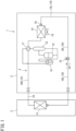
- FIG. 1 is a schematic configuration diagram of an air conditioner according to an embodiment of the present disclosure.
- An air conditioner 1 functioning as a refrigeration apparatus includes an outdoor unit 2 disposed outdoors and an indoor unit 3 disposed indoors.
- the outdoor unit 2 and the indoor unit 3 are connected to each other by a connection pipe.
- the air conditioner 1 includes a refrigerant circuit 4 configured to execute vapor compression refrigeration cycle operation.
- the refrigerant circuit 4 is provided with an indoor heat exchanger 11, a compressor 12, an oil separator 13, an outdoor heat exchanger 14, an expansion valve (expansion mechanism) 15, an accumulator 16, a four-way switching valve 17, and the like, which are connected by a refrigerant pipe 10.
- the refrigerant pipe 10 includes a liquid pipe 10L and a gas pipe 10G.
- the indoor heat exchanger 11 is configured to execute heat exchange between a refrigerant and indoor air, and is provided in the indoor unit 3.
- Examples of the indoor heat exchanger 11 include a fin-and-tube heat exchanger of a cross-fin type and a heat exchanger of a microchannel type.
- the indoor heat exchanger 11 is provided therearound with an indoor fan (not depicted) configured to send indoor air to the indoor heat exchanger 11.
- the compressor 12, the oil separator 13, the outdoor heat exchanger 14, the expansion valve 15, the accumulator 16, and the four-way switching valve 17 are provided in the outdoor unit 2.
- the compressor 12 is configured to compress a refrigerant sucked from a suction port and discharge the compressed refrigerant from a discharge port.
- Examples of the compressor 12 include various compressors such as a scroll compressor.
- the oil separator 13 is configured to separate lubricant from fluid mixture that contains the lubricant and a refrigerant and that is discharged from the compressor 12. The refrigerant thus separated is sent to the four-way switching valve 17 whereas the lubricant is returned to the compressor 12.
- the outdoor heat exchanger 14 is configured to execute heat exchange between a refrigerant and outdoor air.
- the outdoor heat exchanger 14 according to the present embodiment is of the microchannel type.
- the outdoor heat exchanger 14 is provided therearound with an outdoor fan 18 configured to send outdoor air to the outdoor heat exchanger 14.
- the outdoor heat exchanger 14 has a liquid side end connected with a refrigerant flow divider 19 including a capillary tube.
- the expansion valve 15 is disposed between the outdoor heat exchanger 14 and the indoor heat exchanger 11 in the refrigerant circuit 4, and expands an incoming refrigerant to be decompressed to have predetermined pressure.
- Examples of the expansion valve 15 include an electronic expansion valve having a variable opening degree.
- the accumulator 16 is configured to separate an incoming refrigerant into a gas refrigerant and a liquid refrigerant, and is disposed between the suction port of the compressor 12 and the four-way switching valve 17 in the refrigerant circuit 4. The gas refrigerant thus separated by the accumulator 16 is sucked into the compressor 12.
- the four-way switching valve 17 is configured to be switchable between a first state indicated by solid lines in FIG. 1 and a second state indicated by broken lines.
- the four-way switching valve 17 is switched into the first state while the air conditioner 1 executes cooling operation, and the four-way switching valve 17 is switched into the second state while the air conditioner 1 executes heating operation.
- the outdoor heat exchanger 14 When the air conditioner 1 executes cooling operation, the outdoor heat exchanger 14 functions as a refrigerant condenser (radiator) and the indoor heat exchanger 11 functions as a refrigerant evaporator.
- the outdoor heat exchanger 14 functions as a refrigerant condenser and the indoor heat exchanger 11 functions as a refrigerant evaporator.
- the outdoor heat exchanger 14 functions as a refrigerant evaporator and the indoor heat exchanger 11 functions as a refrigerant condenser.
- the gas refrigerant discharged from the compressor 12 condenses at the indoor heat exchanger 11, is then decompressed at the expansion valve 15, and evaporates at the outdoor heat exchanger 14 to be sucked into the compressor 12.
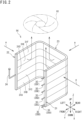
- FIG. 2 is a perspective view depicting the outdoor heat exchanger of the air conditioner.
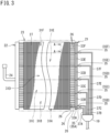
- FIG. 3 is a schematic developed view depicting the outdoor heat exchanger.
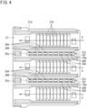
- FIG. 4 is a sectional view taken along arrow A-A indicated in FIG. 3 .
- the following description may include expressions such as “up”, “down”, “left”, “right”, “front (before)”, and “rear (behind)", for indication of directions and positions. These expressions follow directions indicated by arrows in FIG. 2 , unless otherwise specified. Specifically, the following description assumes that a direction indicated by arrow X in FIG. 2 is a lateral direction, a direction indicated by arrow Y is an anteroposterior direction, and a direction indicated by arrow Z is a vertical direction. These expressions describing the directions and the positions are adopted for convenience of description, and do not limit, unless otherwise specified, directions or positions of the entire outdoor heat exchanger 14 and various constituents of the outdoor heat exchanger 14 to the directions or the positions described herein.
- the outdoor heat exchanger 14 is configured to cause heat exchange between a refrigerant flowing inside and air.
- the outdoor heat exchanger 14 according to the present embodiment has a substantially U shape in a top view.
- the outdoor heat exchanger 14 is exemplarily accommodated in a casing of the outdoor unit 2 having a rectangular parallelepiped shape, and is disposed to face three side walls of the casing.
- the outdoor heat exchanger 14 according to the present embodiment includes a pair of headers 21 and 22, and a heat exchanger body 23.
- the pair of headers 21 and 22 and the heat exchanger body 23 are made of aluminum or an aluminum alloy.
- the pair of headers 21 and 22 is disposed at respective ends of the heat exchanger body 23.
- the header 21 is a liquid header configured to allow a liquid refrigerant (gas-liquid two-phase refrigerant) to flow therein.
- the header 22 is a gas header configured to allow a gas refrigerant to flow therein.
- the liquid header 21 and the gas header 22 are each disposed to have a longitudinal direction aligned to a vertical direction Z.
- the liquid header 21 is connected with the refrigerant flow divider 19 including capillary tubes 37A to 37F.
- the gas header 22 is connected with a gas pipe 24.
- the heat exchanger body 23 is configured to execute heat exchange between a refrigerant flowing inside and air. Air passes along arrow a from outside to inside the heat exchanger body 23 having the substantially U shape so as to cross the heat exchanger body 23.
- the heat exchanger body 23 includes a plurality of heat transfer tubes 26 and a plurality of fins 27.
- the plurality of heat transfer tubes 26 is disposed horizontally.
- the plurality of heat transfer tubes 26 is aligned in the vertical direction in parallel with the longitudinal direction of the headers 21 and 22.
- Each of the heat transfer tubes 26 has a first longitudinal end part connected to the liquid header 21.
- Each of the heat transfer tubes 26 has a second longitudinal end part connected to the gas header 22.
- each of the heat transfer tubes 26 is a porous tube provided with a plurality of refrigerant flow paths 30A and 30B.
- the flow paths 30A and 30B extend in a longitudinal direction of the heat transfer tube 26.
- a refrigerant flowing in each of the flow paths 30A and 30B of the heat transfer tube 26 has heat exchange with air.
- the plurality of flow paths 30A and 30B is aligned in an air flow direction a with respect to the heat exchanger body 23. Air passes through a vertical space between the plurality of heat transfer tubes 26.
- the heat transfer tubes 26 each have a flat shape having a vertical length less than a length in an alignment direction of the plurality of flow paths 30A and 30B (the air flow direction a).
- the heat transfer tubes 26 each have respective end surfaces 26a in the alignment direction of the plurality of flow paths 30A and 30B, and the end surfaces 26a each have a semiarcuate shape.
- the plurality of fins 27 is aligned in the longitudinal direction of the heat transfer tubes 26.
- the fins 27 are vertically elongated thin plates.
- the fins 27 are each provided with a plurality of grooves 27a extending from a first side 27c toward a second side in the air flow direction a and aligned to be vertically spaced apart from each other.
- the grooves 27a are opened at the first side 27c of the fin 27.
- the heat transfer tubes 26 are inserted to the grooves 27a of the fins 27 to be attached to the fins 27.
- the fins 27 are each provided with a louver 27b for promotion of heat transfer, and a reinforcing rib 27d.
- the heat exchanger body 23 exemplarily depicted in FIG. 2 and FIG. 3 includes a plurality of heat exchange units 31A to 31F.
- the plurality of heat exchange units 31A to 31F is aligned in the vertical direction.
- the liquid header 21 has an interior vertically zoned respectively for the heat exchange units 31A to 31F.
- the interior of the liquid header 21 is provided with flow paths 33A to 33F respectively for the heat exchange units 31A to 31F.
- the liquid header 21 is connected with a plurality of connecting tubes 35A to 35F.
- the connecting tubes 35Ato 35F are provided correspondingly to the flow paths 33Ato 33F.
- the connecting tubes 35A to 35F are connected with the capillary tubes 37Ato 37F of the refrigerant flow divider 19.
- a liquid refrigerant obtained through dividing by the refrigerant flow divider 19 flows through the capillary tubes 37A to 37F and the connecting tubes 35Ato 35F, flows into the flow paths 33Ato 33F in the liquid header 21, and flows through one or some of the heat transfer tubes 26 connected to the flow paths 33A to 33F to reach the gas header 22.
- a refrigerant divided into the heat transfer tubes 26 at the gas header 22 flows into the flow paths 33A to 33F of the liquid header 21, and flows from the flow paths 33A to 33F to the capillary tubes 37A to 37F to join at the refrigerant flow divider 19.
- the gas header 22 has an interior not zoned but provided continuously for all the heat exchange units 31A to 31F.
- the refrigerant flowing from the single gas pipe 24 into the gas header 22 is accordingly divided into all the heat transfer tubes 26, and the refrigerant flowing from all the heat transfer tubes 26 into the gas header 22 is joined at the gas header 22 to flow into the single gas pipe 24.
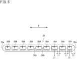
- FIG. 5 is a sectional view of the heat transfer tube.
- FIG. 6 is an enlarged sectional view depicting a first flow path of the heat transfer tube.
- FIG. 7 is an enlarged sectional view depicting a second flow path of the heat transfer tube.
- the heat transfer tube 26 is provided with the plurality of flow paths 30A and 30B.
- the heat transfer tube 26 has respective ends in the air flow direction a each provided with a second flow path 30B.
- the two second flow paths 30B interpose a plurality of aligned first flow paths 30A.
- the present embodiment provides seven first flow paths 30A and the two second flow paths 30B aligned linearly in the air flow direction a.
- an alignment direction of the flow paths 30A and 30B will be also called a "first direction P".
- the first flow path 30A has a rectangular section elongated in the first direction P.
- the section of the first flow path 30A has a long side having a length (length in the first direction P) denoted by L1a, and a short side having a length (length in the vertical direction) denoted by L1b.
- the first flow path 30A has an inner surface provided with a plurality of protrusions 31.
- the plurality of protrusions 31 is provided on inner surfaces located on two long sides in the section of the first flow path 30A.
- FIG. 6 exemplifies a case where the inner surfaces each have six protrusions 31.
- the protrusions 31 are tapered to be gradually reduced in length in the first direction P toward tip ends.
- the second flow path 30B has a rectangular section elongated in the first direction P.
- the section of the second flow path 30B has a long side having a length denoted by L2a, and a short side having a length denoted by L2b.
- the length L2a of the long side of the second flow path 30B is shorter than the length L1a of the long side of the first flow path 30A.
- the length L2b of the short side of the second flow path 30B is equal to the length L1b of the short side of the first flow path 30A.
- the second flow path 30B is smaller in sectional area than the first flow path 30A.
- the second flow path 30B has an inner surface provided with a plurality of protrusions 31.
- the plurality of protrusions 31 is provided on inner surfaces located on two long sides in the section of the second flow path 30B.
- FIG. 7 exemplifies a case where the inner surfaces each have four protrusions 31.
- the protrusions 31 of the second flow path 30B are equal in shape to the protrusions 31 of the first flow path 30A.
- the length L2a of the long side of the second flow path 30B is shorter than the length L1a of the long side of the first flow path 30A, so that the protrusions 31 formable at the second flow path 30B are smaller in the number than the protrusions 31 formable at the first flow path 30A.
- the first flow path 30A has the rectangular section, and the length L1a of the long side and the length L1b of the short side of the rectangular shape have a ratio as an aspect ratio set from 1.1 to 1.5.
- the aspect ratio is set to such a value in consideration of the following matters (1) to (4).
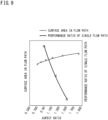
- FIG. 9 is a graph indicating a relation among the aspect ratio, the surface area in the flow path, and a heat exchanging performance ratio of the single flow path. According to FIG. 9 , the surface area in the flow path increases as the aspect ratio of the flow path increases, whereas the heat exchanging performance ratio of each of the flow paths decreases as the aspect ratio increases.
- the inventor of the present application has obtained a relation between the aspect ratio of the flow paths and heat exchanging performance of the heat transfer tube 26 under conditions A to F indicated in Table 1, in consideration of the matters (1) to (4) and the relation indicated in FIG. 9 .
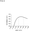
- Table 1 A B C D E F Number of flow paths 16 14 12 10 8 6 Wall thickness (mm) 0.291 0.339 0.405 0.499 0.646 0.899 Length of flow path in first direction (mm) 1.36 1.36 1.36 1.36 1.36 1.36 Length of flow path in vertical direction (mm) 0.972 1.104 1.279 1.521 1.879 2.468 Aspect ratio 0.715 0.812 0.940 1.118 1.382 1.814 Number of grooves between protrusions 1 2 3 4 6 9 Surface area in flow path (mm 2 ) 38.592 40.745 42.833 44.831 46.696 48.340 Heat exchanging performance ratio 100% 103% 106% 107% 107% 106%
- the number of the flow paths is changed under the six conditions A to F in a state where the heat transfer tube 26 has a fixed vertical length (thickness) and a fixed length in the first direction P, to set the thickness of the walls, the aspect ratio, and the number of the protrusions (the number of the grooves) in accordance with the number of the flow paths and obtain the heat exchanging performance ratio.
- the heat exchanging performance ratio is obtained with respect to a ratio assumed to 100% under the condition A.
- the heat transfer tube 26 has the vertical length of 2.0 mm and the length in the first direction P of 22.2 mm.
- FIG. 8 is a graph indicating a relation between the aspect ratio of the flow path indicated in Table 1 and the heat exchanging performance ratio.
- the heat exchanging performance ratio increases while the aspect ratio is from 0.7 to 1.3, and then decreases.
- the aspect ratio exceeds 1.3, the heat exchanging performance ratio will be influenced more largely by increase in thickness of the walls between the flow paths and deterioration in performance of each of the flow paths rather than increase in surface area in the flow paths.
- the heat transfer tube 26 adopts a value from 1.1 to 1.5 as the aspect ratio achieving appropriate heat exchanging performance on the basis of results of Table 1 and FIG. 8 , to set the lengths La1 and La2 of the long side and the short side in the section of the first flow path 30A.
- the first flow paths 30A have a distance (the thickness of the wall 26b) t1 that is appropriately set to be from 0.5 mm to 0.6 mm.
- a cooled refrigerant passes through the heat transfer tube 26 when the outdoor heat exchanger 14 is used as an evaporator, so that the heat transfer tube 26 has lower surface temperature and may have frost.
- the end surface 26a on one side in the first direction P (right end surface) of the heat transfer tube 26 in the outdoor heat exchanger 14 is not in contact with the fin 27, so that heat does not transfer from the end surface 26a of the heat transfer tube 26 cooled by the refrigerant to the fin 27.
- the end surface 26a of the heat transfer tube 26 not in contact with the fin 27 accordingly has significant temperature decrease of the heat transfer tube 26 to be more likely to have frost.
- the end surface 26a of the heat transfer tube 26 not in contact with the fin 27 is positioned upstream in the air flow direction a and is thus in contact with air containing moisture to be more likely to have frost.
- the second flow path 30B is provided at each of the end parts in the heat transfer tube 26 in the first direction P.
- the second flow path 30B is smaller in sectional area than the first flow path 30A.
- the second flow path 30B is thus smaller in volume of the refrigerant flowing therein than the first flow path 30A, and has smaller volume of heat transfer to the end surface 26a of the heat transfer tube 26.
- Provision of the second flow path 30B at each of the end parts in the first direction P in the heat transfer tube 26 can thus achieve inhibition of frost on the end surface 26a of the heat transfer tube 26.
- the second flow path 30B has an aspect ratio that is set to be less than 1.1, not within the range from 1.1 to 1.5 as the aspect ratio of the first flow path 30A.
- a maximum distance (thickness at the end part of the heat transfer tube 26) t2 in the first direction P between the second flow path 30B and the end surface 26a of the heat transfer tube 26 in the first direction P closest to the second flow path 30B is larger than the distance (thickness of the wall 26b) t1 in the first direction P between the first flow path 30A and the first flow path 30A.
- Heat of the refrigerant flowing in the second flow path 30B is thus less likely to be transferred to the end surface 26a of the heat transfer tube 26 for further inhibition of frost.
- the distance (the thickness of the wall 26b) t1 between the first flow path 30A and the second flow path 30B is also equal to the distance t1 between the first flow paths 30A.
- the groove 27a provided in the fin 27 has a first portion 27a1 having a vertical length L3 substantially equal to the vertical length of the heat transfer tube 26, and a second portion 27a2 disposed in an end part of the fin 27 in the first direction P and having a larger vertical length than the first portion 27a1.
- FIG. 7 includes L4 denoting a maximum vertical length in the second portion 27a2, and W denoting a range of the second portion 27a2 in the first direction P.
- the end surface 26a of the heat transfer tube 26 has the semiarcuate section.
- the end surface 26a of the heat transfer tube 26 has a part disposed in the first portion 27a1 of the groove 27a, and a remaining part disposed in the range W in the first direction P of the second portion 27a2 of the groove 27a.
- the end surface 26a of the heat transfer tube 26 and the first portion 27a1 of the groove 27a are disposed close to each other with a space S provided therebetween.
- the end surface 26a of the heat transfer tube 26 has a radius of about 1.0 mm, and the end surface 26a of the heat transfer tube 26 disposed in the second portion 27a2 has a length L5 in the first direction P, and the length L5 is exemplarily from 0.20 mm to 0.24 mm, and is more preferably 0.22 mm.
- the protrusions 31 provided at the first flow path 30A and the second flow path 30B may alternatively be provided on the inner surfaces located on the short sides in the sections of the first flow path 30A and the second flow path 30B, or may still alternatively be provided on both the inner surfaces located on the long sides and the inner surfaces located on the short sides.
- the second flow path 30B has the rectangular section.
- the section may have a square shape.
- the end surface 26a in the first direction P of the heat transfer tube 26 has the semiarcuate shape.
- the end surface 26a may alternatively have a flat surface extending in the vertical direction.
Description
- The present disclosure relates to a heat transfer tube and a heat exchanger.
- Recent air conditioners may include microchannel heat exchangers having high heat exchange efficiency and enabling reduction in size and weight. Such a microchannel heat exchanger includes a heat transfer tube that has a plurality of aligned internal flow paths and is called a porous tube (see
Japanese Laid-Open Patent Publication No. 2009-63228 Japanese Laid-Open Patent Publication No. 2009-63228 JP 2000 018867 - In the heat transfer tube of
JP 2009-63228 - It is an object of the present disclosure to provide a heat transfer tube and a heat exchanger that can improve heat exchanging performance.
- According to a first aspect, there is provided a heat transfer tube according to claim 1.
- The above configuration enables appropriate setting of the ratio between the long side and the short side in the section of the first flow paths and improvement in heat exchanging performance.
- (2) Preferably, the first flow paths adjacent to each other have a distance from 0.5 mm to 0.6 mm.
- The heat transfer tube has an inner end part in the first direction provided with a second flow path, and
the second flow path has a sectional area smaller than a sectional area of the first flow paths. - According to this configuration, the heat transfer tube is likely to have frost on an end surface in the first direction. The sectional area of the second flow path is thus made smaller than the sectional area of the first flow path such that the second flow path is smaller in refrigerant flow rate than the first flow path for inhibition of frost.
- (4) Preferably, the second flow path is provided at each inner end part of the heat transfer tube in the first direction.
- (5) Preferably, a maximum distance in the first direction between the second flow path and an end surface of the heat transfer tube in the first direction closest to the second flow path is larger than a distance in the first direction between two of the first flow paths adjacent to each other.
- According to this configuration, the heat transfer tube is likely to have frost on the end surface in the first direction. The maximum distance in the first direction between the second flow path and the end surface of the heat transfer tube is thus made longer than the distance in the first direction between the adjacent first flow paths such that heat of the refrigerant flowing in the second flow path is less likely to be transferred to the end surface of the heat transfer tube for inhibition of frost on the end surface.
- (6) The present disclosure provides a heat exchanger including:
- headers;
- a plurality of heat transfer tubes according to any one of the (1) to (5), the heat transfer tubes aligned in a longitudinal direction of the headers and having the end parts connected to the headers.
- According to a second aspect, there is provided a heat exchanger according to claim 6.
- According to the above configuration, the end surface on the side of the heat transfer tube not in contact with the fin is lower in temperature than the remaining surface in contact with the fin and is thus likely to have frost. The second flow path is provided at the end part on the side of the heat transfer tube to reduce the refrigerant flow rate around the end surface on the side of the heat transfer tube, for inhibition of frost.
-
-
FIG. 1 is a schematic configuration diagram of an air conditioner according to an embodiment of the present disclosure. -
FIG. 2 is a perspective view depicting an outdoor heat exchanger of the air conditioner. -
FIG. 3 is a schematic developed view depicting the outdoor heat exchanger. -
FIG. 4 is a sectional view taken along arrow A-A indicated inFIG. 3 . -
FIG. 5 is a sectional view of a heat transfer tube. -
FIG. 6 is an enlarged sectional view depicting a first flow path of the heat transfer tube. -
FIG. 7 is an enlarged sectional view depicting a second flow path of the heat transfer tube. -
FIG. 8 is a graph indicating a relation between an aspect ratio and a heat exchanging performance ratio. -
FIG. 9 is a graph indicating a relation among the aspect ratio, a surface area in a flow path, and the heat exchanging performance ratio of a single flow path. - Embodiments of the present disclosure will be described in detail hereinafter with reference to the accompanying drawings.
-
FIG. 1 is a schematic configuration diagram of an air conditioner according to an embodiment of the present disclosure. - An air conditioner 1 functioning as a refrigeration apparatus includes an
outdoor unit 2 disposed outdoors and anindoor unit 3 disposed indoors. Theoutdoor unit 2 and theindoor unit 3 are connected to each other by a connection pipe. The air conditioner 1 includes arefrigerant circuit 4 configured to execute vapor compression refrigeration cycle operation. Therefrigerant circuit 4 is provided with anindoor heat exchanger 11, acompressor 12, anoil separator 13, anoutdoor heat exchanger 14, an expansion valve (expansion mechanism) 15, anaccumulator 16, a four-way switching valve 17, and the like, which are connected by arefrigerant pipe 10. Therefrigerant pipe 10 includes aliquid pipe 10L and agas pipe 10G. - The
indoor heat exchanger 11 is configured to execute heat exchange between a refrigerant and indoor air, and is provided in theindoor unit 3. Examples of theindoor heat exchanger 11 include a fin-and-tube heat exchanger of a cross-fin type and a heat exchanger of a microchannel type. Theindoor heat exchanger 11 is provided therearound with an indoor fan (not depicted) configured to send indoor air to theindoor heat exchanger 11. - The
compressor 12, theoil separator 13, theoutdoor heat exchanger 14, theexpansion valve 15, theaccumulator 16, and the four-way switching valve 17 are provided in theoutdoor unit 2. - The
compressor 12 is configured to compress a refrigerant sucked from a suction port and discharge the compressed refrigerant from a discharge port. Examples of thecompressor 12 include various compressors such as a scroll compressor. - The
oil separator 13 is configured to separate lubricant from fluid mixture that contains the lubricant and a refrigerant and that is discharged from thecompressor 12. The refrigerant thus separated is sent to the four-way switching valve 17 whereas the lubricant is returned to thecompressor 12. - The
outdoor heat exchanger 14 is configured to execute heat exchange between a refrigerant and outdoor air. Theoutdoor heat exchanger 14 according to the present embodiment is of the microchannel type. Theoutdoor heat exchanger 14 is provided therearound with anoutdoor fan 18 configured to send outdoor air to theoutdoor heat exchanger 14. Theoutdoor heat exchanger 14 has a liquid side end connected with arefrigerant flow divider 19 including a capillary tube. - The
expansion valve 15 is disposed between theoutdoor heat exchanger 14 and theindoor heat exchanger 11 in therefrigerant circuit 4, and expands an incoming refrigerant to be decompressed to have predetermined pressure. Examples of theexpansion valve 15 include an electronic expansion valve having a variable opening degree. - The
accumulator 16 is configured to separate an incoming refrigerant into a gas refrigerant and a liquid refrigerant, and is disposed between the suction port of thecompressor 12 and the four-way switching valve 17 in therefrigerant circuit 4. The gas refrigerant thus separated by theaccumulator 16 is sucked into thecompressor 12. - The four-
way switching valve 17 is configured to be switchable between a first state indicated by solid lines inFIG. 1 and a second state indicated by broken lines. The four-way switching valve 17 is switched into the first state while the air conditioner 1 executes cooling operation, and the four-way switching valve 17 is switched into the second state while the air conditioner 1 executes heating operation. - When the air conditioner 1 executes cooling operation, the
outdoor heat exchanger 14 functions as a refrigerant condenser (radiator) and theindoor heat exchanger 11 functions as a refrigerant evaporator. A gas refrigerant discharged from thecompressor 12 condenses at theoutdoor heat exchanger 14, is then decompressed at theexpansion valve 15, and evaporates at theindoor heat exchanger 11 to be sucked into thecompressor 12. Also during defrosting operation of removing frost adhering to theoutdoor heat exchanger 14 due to heating operation, as in cooling operation, theoutdoor heat exchanger 14 functions as a refrigerant condenser and theindoor heat exchanger 11 functions as a refrigerant evaporator. - When the air conditioner 1 executes heating operation, the
outdoor heat exchanger 14 functions as a refrigerant evaporator and theindoor heat exchanger 11 functions as a refrigerant condenser. The gas refrigerant discharged from thecompressor 12 condenses at theindoor heat exchanger 11, is then decompressed at theexpansion valve 15, and evaporates at theoutdoor heat exchanger 14 to be sucked into thecompressor 12. -
FIG. 2 is a perspective view depicting the outdoor heat exchanger of the air conditioner.FIG. 3 is a schematic developed view depicting the outdoor heat exchanger.FIG. 4 is a sectional view taken along arrow A-A indicated inFIG. 3 . - The following description may include expressions such as "up", "down", "left", "right", "front (before)", and "rear (behind)", for indication of directions and positions. These expressions follow directions indicated by arrows in
FIG. 2 , unless otherwise specified. Specifically, the following description assumes that a direction indicated by arrow X inFIG. 2 is a lateral direction, a direction indicated by arrow Y is an anteroposterior direction, and a direction indicated by arrow Z is a vertical direction. These expressions describing the directions and the positions are adopted for convenience of description, and do not limit, unless otherwise specified, directions or positions of the entireoutdoor heat exchanger 14 and various constituents of theoutdoor heat exchanger 14 to the directions or the positions described herein. - The
outdoor heat exchanger 14 is configured to cause heat exchange between a refrigerant flowing inside and air. Theoutdoor heat exchanger 14 according to the present embodiment has a substantially U shape in a top view. Theoutdoor heat exchanger 14 is exemplarily accommodated in a casing of theoutdoor unit 2 having a rectangular parallelepiped shape, and is disposed to face three side walls of the casing. Theoutdoor heat exchanger 14 according to the present embodiment includes a pair ofheaders heat exchanger body 23. The pair ofheaders heat exchanger body 23 are made of aluminum or an aluminum alloy. - The pair of
headers heat exchanger body 23. Theheader 21 is a liquid header configured to allow a liquid refrigerant (gas-liquid two-phase refrigerant) to flow therein. Theheader 22 is a gas header configured to allow a gas refrigerant to flow therein. Theliquid header 21 and thegas header 22 are each disposed to have a longitudinal direction aligned to a vertical direction Z. Theliquid header 21 is connected with therefrigerant flow divider 19 includingcapillary tubes 37A to 37F. Thegas header 22 is connected with agas pipe 24. - The
heat exchanger body 23 is configured to execute heat exchange between a refrigerant flowing inside and air. Air passes along arrow a from outside to inside theheat exchanger body 23 having the substantially U shape so as to cross theheat exchanger body 23. - As depicted in
FIG. 3 , theheat exchanger body 23 includes a plurality ofheat transfer tubes 26 and a plurality offins 27. The plurality ofheat transfer tubes 26 is disposed horizontally. The plurality ofheat transfer tubes 26 is aligned in the vertical direction in parallel with the longitudinal direction of theheaders heat transfer tubes 26 has a first longitudinal end part connected to theliquid header 21. Each of theheat transfer tubes 26 has a second longitudinal end part connected to thegas header 22. - As depicted in
FIG. 4 , each of theheat transfer tubes 26 according to the present embodiment is a porous tube provided with a plurality ofrefrigerant flow paths flow paths heat transfer tube 26. A refrigerant flowing in each of theflow paths heat transfer tube 26 has heat exchange with air. The plurality offlow paths heat exchanger body 23. Air passes through a vertical space between the plurality ofheat transfer tubes 26. Theheat transfer tubes 26 each have a flat shape having a vertical length less than a length in an alignment direction of the plurality offlow paths heat transfer tubes 26 each haverespective end surfaces 26a in the alignment direction of the plurality offlow paths - The plurality of
fins 27 is aligned in the longitudinal direction of theheat transfer tubes 26. Thefins 27 are vertically elongated thin plates. Thefins 27 are each provided with a plurality ofgrooves 27a extending from afirst side 27c toward a second side in the air flow direction a and aligned to be vertically spaced apart from each other. Thegrooves 27a are opened at thefirst side 27c of thefin 27. Theheat transfer tubes 26 are inserted to thegrooves 27a of thefins 27 to be attached to thefins 27. Thefins 27 are each provided with alouver 27b for promotion of heat transfer, and a reinforcingrib 27d. - The
heat exchanger body 23 exemplarily depicted inFIG. 2 andFIG. 3 includes a plurality ofheat exchange units 31A to 31F. The plurality ofheat exchange units 31A to 31F is aligned in the vertical direction. Theliquid header 21 has an interior vertically zoned respectively for theheat exchange units 31A to 31F. In other words, as depicted inFIG. 3 , the interior of theliquid header 21 is provided withflow paths 33A to 33F respectively for theheat exchange units 31A to 31F. - The
liquid header 21 is connected with a plurality of connectingtubes 35A to 35F. The connectingtubes 35Ato 35F are provided correspondingly to theflow paths 33Ato 33F. The connectingtubes 35A to 35F are connected with thecapillary tubes 37Ato 37F of therefrigerant flow divider 19. - During heating operation, a liquid refrigerant obtained through dividing by the
refrigerant flow divider 19 flows through thecapillary tubes 37A to 37F and the connectingtubes 35Ato 35F, flows into theflow paths 33Ato 33F in theliquid header 21, and flows through one or some of theheat transfer tubes 26 connected to theflow paths 33A to 33F to reach thegas header 22. In contrast, during cooling operation or defrosting operation, a refrigerant divided into theheat transfer tubes 26 at thegas header 22 flows into theflow paths 33A to 33F of theliquid header 21, and flows from theflow paths 33A to 33F to thecapillary tubes 37A to 37F to join at therefrigerant flow divider 19. - The
gas header 22 has an interior not zoned but provided continuously for all theheat exchange units 31A to 31F. The refrigerant flowing from thesingle gas pipe 24 into thegas header 22 is accordingly divided into all theheat transfer tubes 26, and the refrigerant flowing from all theheat transfer tubes 26 into thegas header 22 is joined at thegas header 22 to flow into thesingle gas pipe 24. -
FIG. 5 is a sectional view of the heat transfer tube.FIG. 6 is an enlarged sectional view depicting a first flow path of the heat transfer tube.FIG. 7 is an enlarged sectional view depicting a second flow path of the heat transfer tube. - As depicted in
FIG. 5 , theheat transfer tube 26 is provided with the plurality offlow paths heat transfer tube 26 has respective ends in the air flow direction a each provided with asecond flow path 30B. The twosecond flow paths 30B interpose a plurality of alignedfirst flow paths 30A. The present embodiment provides sevenfirst flow paths 30A and the twosecond flow paths 30B aligned linearly in the air flow direction a. Hereinafter, an alignment direction of theflow paths - As depicted in
FIG. 6 , thefirst flow path 30A has a rectangular section elongated in the first direction P. InFIG. 6 , the section of thefirst flow path 30A has a long side having a length (length in the first direction P) denoted by L1a, and a short side having a length (length in the vertical direction) denoted by L1b. Thefirst flow path 30A has an inner surface provided with a plurality ofprotrusions 31. Specifically, the plurality ofprotrusions 31 is provided on inner surfaces located on two long sides in the section of thefirst flow path 30A.FIG. 6 exemplifies a case where the inner surfaces each have sixprotrusions 31. Theprotrusions 31 are tapered to be gradually reduced in length in the first direction P toward tip ends. - As depicted in
FIG. 7 , thesecond flow path 30B has a rectangular section elongated in the first direction P. InFIG. 7 , the section of thesecond flow path 30B has a long side having a length denoted by L2a, and a short side having a length denoted by L2b. The length L2a of the long side of thesecond flow path 30B is shorter than the length L1a of the long side of thefirst flow path 30A. The length L2b of the short side of thesecond flow path 30B is equal to the length L1b of the short side of thefirst flow path 30A. Thesecond flow path 30B is smaller in sectional area than thefirst flow path 30A. - The
second flow path 30B has an inner surface provided with a plurality ofprotrusions 31. Specifically, the plurality ofprotrusions 31 is provided on inner surfaces located on two long sides in the section of thesecond flow path 30B.FIG. 7 exemplifies a case where the inner surfaces each have fourprotrusions 31. Theprotrusions 31 of thesecond flow path 30B are equal in shape to theprotrusions 31 of thefirst flow path 30A. The length L2a of the long side of thesecond flow path 30B is shorter than the length L1a of the long side of thefirst flow path 30A, so that theprotrusions 31 formable at thesecond flow path 30B are smaller in the number than theprotrusions 31 formable at thefirst flow path 30A. - Provision of the
protrusions 31 on the inner surfaces of the first andsecond flow paths - The first flow path 30Ahas the rectangular section, and the length L1a of the long side and the length L1b of the short side of the rectangular shape have a ratio as an aspect ratio set from 1.1 to 1.5. The aspect ratio is set to such a value in consideration of the following matters (1) to (4).
- (1) As depicted in
FIG. 4 , when air flows in the alignment direction of thefirst flow paths 30A (hereinafter, also simply called "flow paths") in theheat transfer tube 26, the refrigerant in theflow paths 30A and air have a large temperature difference on an upstream side in the air flow direction a (right side inFIG. 4 ) to achieve efficient heat exchange. In contrast, air having had heat exchange on the upstream side flows to a downstream side in the air flow direction a (left side inFIG. 4 ), so that the refrigerant in theflow paths 30A and such air have a small temperature difference. The downstream side thus has lower heat exchange efficiency than the upstream side. The refrigerant flowing in theflow path 30A disposed upstream in the air flow direction a and the refrigerant flowing in theflow path 30A disposed downstream in the air flow direction a are different from each other in terms of timing of state change. Theoutdoor heat exchanger 14 is thus designed to cause appropriate state change of the refrigerant in thedownstream flow path 30A. However, if theupstream flow path 30A and thedownstream flow path 30A have a large difference in heat exchange efficiency, theupstream flow path 30A has a flow of the refrigerant having been changed in state into theoutdoor heat exchanger 14 with waste of performance. This phenomenon is inhibited when theflow paths 30A in theheat transfer tube 26 are reduced in the number without reduction in total sectional area of theflow paths 30A. The section of each of the flow paths 30Ais thus usefully formed into the rectangular shape elongated in the air flow direction a. - (2) When the section of the
flow path 30A is formed into the rectangular shape on the basis of the idea of the above (1), themore protrusions 31 can be provided on the inner surface of the long side of the flow path 30Aas the long side is made longer (as the aspect ratio is increased). Theflow path 30A can thus be increased in surface area, to expect improvement in heat exchange efficiency. - (3) However, increase in length of the long side in the section of the
flow path 30A leads to decrease in the number of theflow paths 30A in theheat transfer tube 26 and decrease in the number ofwalls 26b (seeFIG. 5 ) partitioning between theflow path 30A and theflow path 30A, which deteriorates strength of theheat transfer tube 26. Thewalls 26b need to be increased in thickness t1 to prevent deterioration in strength of theheat transfer tube 26. Accordingly, increase in length of the long side in the section of theflow path 30A does not proportionally lead to increase in surface area of theflow path 30A. - (4) Increase in length of the long side in the section of each of the
flow paths 30A leads to decrease in flow speed of the refrigerant in theflow path 30A, so that each of the flow paths (single flow path) 30A may have deteriorated heat exchanging performance. Furthermore, increase in length of the long side in the section of theflow path 30A generates a region where the refrigerant is not in contact with the inner surface of theflow path 30A around a center of the long side in the inner surface of theflow path 30A. The region in the inner surface not in contact with the refrigerant cannot achieve heat exchange with the refrigerant, which leads to deterioration in heat exchange efficiency. -
FIG. 9 is a graph indicating a relation among the aspect ratio, the surface area in the flow path, and a heat exchanging performance ratio of the single flow path. According toFIG. 9 , the surface area in the flow path increases as the aspect ratio of the flow path increases, whereas the heat exchanging performance ratio of each of the flow paths decreases as the aspect ratio increases. - The inventor of the present application has obtained a relation between the aspect ratio of the flow paths and heat exchanging performance of the
heat transfer tube 26 under conditions A to F indicated in Table 1, in consideration of the matters (1) to (4) and the relation indicated inFIG. 9 .[Table 1] A B C D E F Number of flow paths 16 14 12 10 8 6 Wall thickness (mm) 0.291 0.339 0.405 0.499 0.646 0.899 Length of flow path in first direction (mm) 1.36 1.36 1.36 1.36 1.36 1.36 Length of flow path in vertical direction (mm) 0.972 1.104 1.279 1.521 1.879 2.468 Aspect ratio 0.715 0.812 0.940 1.118 1.382 1.814 Number of grooves between protrusions 1 2 3 4 6 9 Surface area in flow path (mm2) 38.592 40.745 42.833 44.831 46.696 48.340 Heat exchanging performance ratio 100% 103% 106% 107% 107% 106% - In Table 1, the number of the flow paths is changed under the six conditions A to F in a state where the
heat transfer tube 26 has a fixed vertical length (thickness) and a fixed length in the first direction P, to set the thickness of the walls, the aspect ratio, and the number of the protrusions (the number of the grooves) in accordance with the number of the flow paths and obtain the heat exchanging performance ratio. The heat exchanging performance ratio is obtained with respect to a ratio assumed to 100% under the condition A. Theheat transfer tube 26 has the vertical length of 2.0 mm and the length in the first direction P of 22.2 mm. -
FIG. 8 is a graph indicating a relation between the aspect ratio of the flow path indicated in Table 1 and the heat exchanging performance ratio. - As indicated in
FIG. 8 , the heat exchanging performance ratio increases while the aspect ratio is from 0.7 to 1.3, and then decreases. When the aspect ratio exceeds 1.3, the heat exchanging performance ratio will be influenced more largely by increase in thickness of the walls between the flow paths and deterioration in performance of each of the flow paths rather than increase in surface area in the flow paths. Theheat transfer tube 26 according to the present embodiment adopts a value from 1.1 to 1.5 as the aspect ratio achieving appropriate heat exchanging performance on the basis of results of Table 1 andFIG. 8 , to set the lengths La1 and La2 of the long side and the short side in the section of thefirst flow path 30A. - The
first flow paths 30A have a distance (the thickness of thewall 26b) t1 that is appropriately set to be from 0.5 mm to 0.6 mm. - As depicted in
FIG. 5 andFIG. 7 , a cooled refrigerant passes through theheat transfer tube 26 when theoutdoor heat exchanger 14 is used as an evaporator, so that theheat transfer tube 26 has lower surface temperature and may have frost. Particularly, as depicted inFIG. 4 , theend surface 26a on one side in the first direction P (right end surface) of theheat transfer tube 26 in theoutdoor heat exchanger 14 is not in contact with thefin 27, so that heat does not transfer from theend surface 26a of theheat transfer tube 26 cooled by the refrigerant to thefin 27. Theend surface 26a of theheat transfer tube 26 not in contact with thefin 27 accordingly has significant temperature decrease of theheat transfer tube 26 to be more likely to have frost. Theend surface 26a of theheat transfer tube 26 not in contact with thefin 27 is positioned upstream in the air flow direction a and is thus in contact with air containing moisture to be more likely to have frost. - According to the present embodiment, the
second flow path 30B is provided at each of the end parts in theheat transfer tube 26 in the first direction P. Thesecond flow path 30B is smaller in sectional area than thefirst flow path 30A. Thesecond flow path 30B is thus smaller in volume of the refrigerant flowing therein than thefirst flow path 30A, and has smaller volume of heat transfer to theend surface 26a of theheat transfer tube 26. Provision of thesecond flow path 30B at each of the end parts in the first direction P in theheat transfer tube 26 can thus achieve inhibition of frost on theend surface 26a of theheat transfer tube 26. Thesecond flow path 30B has an aspect ratio that is set to be less than 1.1, not within the range from 1.1 to 1.5 as the aspect ratio of thefirst flow path 30A. - As depicted in
FIG. 5 andFIG. 7 , a maximum distance (thickness at the end part of the heat transfer tube 26) t2 in the first direction P between thesecond flow path 30B and theend surface 26a of theheat transfer tube 26 in the first direction P closest to thesecond flow path 30B is larger than the distance (thickness of thewall 26b) t1 in the first direction P between thefirst flow path 30A and thefirst flow path 30A. Heat of the refrigerant flowing in thesecond flow path 30B is thus less likely to be transferred to theend surface 26a of theheat transfer tube 26 for further inhibition of frost. The distance (the thickness of thewall 26b) t1 between thefirst flow path 30A and thesecond flow path 30B is also equal to the distance t1 between thefirst flow paths 30A. - As depicted in
FIG. 7 , thegroove 27a provided in thefin 27 has a first portion 27a1 having a vertical length L3 substantially equal to the vertical length of theheat transfer tube 26, and a second portion 27a2 disposed in an end part of thefin 27 in the first direction P and having a larger vertical length than the first portion 27a1.FIG. 7 includes L4 denoting a maximum vertical length in the second portion 27a2, and W denoting a range of the second portion 27a2 in the first direction P. - The
end surface 26a of theheat transfer tube 26 has the semiarcuate section. Theend surface 26a of theheat transfer tube 26 has a part disposed in the first portion 27a1 of thegroove 27a, and a remaining part disposed in the range W in the first direction P of the second portion 27a2 of thegroove 27a. Theend surface 26a of theheat transfer tube 26 and the first portion 27a1 of thegroove 27a are disposed close to each other with a space S provided therebetween. - The
end surface 26a of theheat transfer tube 26 has a radius of about 1.0 mm, and theend surface 26a of theheat transfer tube 26 disposed in the second portion 27a2 has a length L5 in the first direction P, and the length L5 is exemplarily from 0.20 mm to 0.24 mm, and is more preferably 0.22 mm. - The
protrusions 31 provided at thefirst flow path 30A and thesecond flow path 30B may alternatively be provided on the inner surfaces located on the short sides in the sections of thefirst flow path 30A and thesecond flow path 30B, or may still alternatively be provided on both the inner surfaces located on the long sides and the inner surfaces located on the short sides. - The
second flow path 30B according to the above embodiment has the rectangular section. The section may have a square shape. - The
end surface 26a in the first direction P of theheat transfer tube 26 according to the above embodiment has the semiarcuate shape. Theend surface 26a may alternatively have a flat surface extending in the vertical direction. -
- (1) The
heat transfer tube 26 according to the above embodiment includes the plurality offirst flow paths 30A aligned in the heat transfer tube, in which thefirst flow paths 30A each have the section in the rectangular shape elongated in the first direction P in parallel with the alignment direction of the plurality offirst flow paths 30A, thefirst flow paths 30A each have the inner surface provided with the plurality ofprotrusions 31, and the section of each of thefirst flow paths 30A has the long side having the length L1a and the short side having the length L1b, the lengths having the ratio from 1.1 to 1.5. This enables appropriate setting of the ratio in length between the long side and the short side in the section of thefirst flow paths 30A and improvement in heat exchanging performance. - (3) According to the above embodiment, the
heat transfer tube 26 has the inner end part in the first direction P provided with thesecond flow path 30B, and thesecond flow path 30B has the sectional area smaller than the sectional area of thefirst flow paths 30A. Theheat transfer tube 26 is likely to have frost at the end part in the first direction P. The sectional area of thesecond flow path 30B is thus made smaller than the sectional area of thefirst flow path 30A such that thesecond flow path 30B is made small in refrigerant flow rate for inhibition of frost. - (4) According to the above embodiment, the
second flow path 30B is provided at each inner end part of theheat transfer tube 26 in the first direction P. This can thus achieve inhibition of frost at the respective end parts of theheat transfer tube 26 in the first direction P. - (5) According to the above embodiment, the maximum distance t2 in the first direction P between the
second flow path 30B and theend surface 26a of theheat transfer tube 26 in the first direction P closest to thesecond flow path 30B is larger than the distance t1 in the first direction P between two of thefirst flow paths 30A adjacent to each other. Theheat transfer tube 26 is likely to have frost on theend surface 26a in the first direction P. The maximum distance t2 between thesecond flow path 30B and theend surface 26a of theheat transfer tube 26 is thus made longer than the distance t1 between the adjacentfirst flow paths 30A such that heat of the refrigerant flowing in thesecond flow path 30B is less likely to be transferred to theend surface 26a of theheat transfer tube 26 for inhibition of frost. - (6) The
outdoor heat exchanger 14 according to the above embodiment includes theheaders heat transfer tubes 26 aligned in the longitudinal direction of theheaders headers fin 27 in contact with the outer circumferential surface of each of theheat transfer tubes 26, in which thefin 27 is in contact with the outer circumferential surface of theheat transfer tube 26 except theend surface 26a on the side of theheat transfer tube 26 in the first direction P, and thesecond flow path 30B is provided on the side in theheat transfer tube 26. Theend surface 26a on the side of theheat transfer tube 26 not in contact with thefin 27 is lower in temperature than the remaining portion in contact with thefin 27 and is thus likely to have frost. Thesecond flow path 30B is provided at the end part on the side in theheat transfer tube 26 to reduce the refrigerant flow rate for inhibition of frost. -
- 21
- liquid header
- 22
- gas header
- 26
- heat transfer tube
- 26a
- end surface
- 27
- fin
- 30A
- first flow path
- 30B
- second flow path
- 31
- protrusion
Claims (6)
- A heat transfer tube comprising:a plurality of first flow paths (30A) aligned in the heat transfer tube, whereinthe first flow paths (30A) each have a section in a rectangular shape elongated in a first direction (P) in parallel with an alignment direction of the plurality of first flow paths (30A),the first flow paths (30A) each have an inner surface provided with a plurality of protrusions (31), andthe section of each of the first flow paths (30A) has a long side having a length (L1a) and a short side having a length (L1b), the lengths having a ratio from 1.1 to 1.5;wherein the heat transfer tube has an inner end part in the first direction (P) provided with a second flow path (30B) at each end of heat transfer tube (26) in the first direction (P), the heat transfer tube being characterized in that the second flow path has a rectangular section elongated in the first direction (P), andthe second flow path (30B) has a sectional area smaller than a sectional area of the first flow paths (30A), and wherein an aspect ratio of the second flow path is less than 1.1.
- The heat transfer tube according to claim 1, wherein the first flow paths (30A) adjacent to each other have a distance (t1) from 0.5 mm to 0.6 mm.
- The heat transfer tube according to claim 1, wherein the second flow path (30B) is provided at each inner end part of the heat transfer tube in the first direction (P).
- The heat transfer tube according to claim 3, wherein a maximum distance (t2) in the first direction (P) between the second flow path (30B) and an end surface of the heat transfer tube in the first direction (P) closest to the second flow path (30B) is larger than a distance (t1) in the first direction (P) between two of the first flow paths (30A) adjacent to each other.
- A heat exchanger comprising:headers (21, 22);a plurality of heat transfer tubes according to any one of claims 1 to 4, the heat transfer tubes aligned in a longitudinal direction of the headers (21, 22) and having the end parts connected to the headers (21, 22).
- A heat exchanger comprising:headers (21, 22);a plurality of heat transfer tubes according to any one of claims 1 to 4, the heat transfer tubes aligned in a longitudinal direction of the headers (21, 22) and having the end parts connected to the headers (21, 22); anda fin (27); whereinthe fin (27) is in contact with an outer circumferential surface of each of the heat transfer tubes (26) except an end surface (26a) on a side of the heat transfer tube (26) in the first direction (P).
Applications Claiming Priority (2)
| Application Number | Priority Date | Filing Date | Title |
|---|---|---|---|
| JP2019205903A JP2021081081A (en) | 2019-11-14 | 2019-11-14 | Heat transfer pipe and heat exchanger |
| PCT/JP2020/040840 WO2021095567A1 (en) | 2019-11-14 | 2020-10-30 | Heat transfer pipe and heat exchanger |
Publications (3)
| Publication Number | Publication Date |
|---|---|
| EP4060252A1 EP4060252A1 (en) | 2022-09-21 |
| EP4060252A4 EP4060252A4 (en) | 2022-12-07 |
| EP4060252B1 true EP4060252B1 (en) | 2023-09-13 |
Family
ID=75912335
Family Applications (1)
| Application Number | Title | Priority Date | Filing Date |
|---|---|---|---|
| EP20887565.8A Active EP4060252B1 (en) | 2019-11-14 | 2020-10-30 | Heat transfer pipe and heat exchanger |
Country Status (5)
| Country | Link |
|---|---|
| US (1) | US20220268525A1 (en) |
| EP (1) | EP4060252B1 (en) |
| JP (2) | JP2021081081A (en) |
| CN (1) | CN114729793B (en) |
| WO (1) | WO2021095567A1 (en) |
Families Citing this family (1)
| Publication number | Priority date | Publication date | Assignee | Title |
|---|---|---|---|---|
| KR20200078936A (en) * | 2018-12-24 | 2020-07-02 | 삼성전자주식회사 | Heat exchanger |
Family Cites Families (21)
| Publication number | Priority date | Publication date | Assignee | Title |
|---|---|---|---|---|
| JPS5913877U (en) * | 1982-07-13 | 1984-01-27 | 株式会社デンソー | Heat exchanger |
| JPH02166393A (en) * | 1988-12-16 | 1990-06-27 | Matsushita Refrig Co Ltd | Heat exchanger with fin |
| JPH06185885A (en) * | 1992-07-24 | 1994-07-08 | Furukawa Electric Co Ltd:The | Flat multi-holed condensing and heat transfer pipe |
| JPH06300473A (en) * | 1993-04-19 | 1994-10-28 | Sanden Corp | Flat refrigerant pipe |
| JPH1144498A (en) * | 1997-05-30 | 1999-02-16 | Showa Alum Corp | Flat porous tube for heat exchanger and heat exchanger using the tube |
| JP2000018867A (en) * | 1998-06-23 | 2000-01-18 | Mitsubishi Heavy Ind Ltd | Tube material for heat exchanger and heat exchanger |
| JP2000154987A (en) * | 1998-11-19 | 2000-06-06 | Daikin Ind Ltd | Air heat exchanger |
| JP2000329487A (en) * | 1999-05-21 | 2000-11-30 | Bosch Automotive Systems Corp | Heat exchanger |
| JP2002318086A (en) * | 2001-04-16 | 2002-10-31 | Japan Climate Systems Corp | Heat exchanger tube |
| JP4328512B2 (en) | 2001-10-23 | 2009-09-09 | 昭和電工株式会社 | Die for extruding fine multi-hole tube, mandrel used for the die, and multi-hole tube manufactured using the die |
| JP2005090760A (en) * | 2003-09-12 | 2005-04-07 | Matsushita Electric Ind Co Ltd | Heat exchanger |
| JP2006162085A (en) * | 2004-12-02 | 2006-06-22 | Matsushita Electric Ind Co Ltd | Flat tube for heat exchanger |
| JP2009063228A (en) * | 2007-09-06 | 2009-03-26 | Showa Denko Kk | Flat heat transfer tube |
| JP5579134B2 (en) * | 2011-07-11 | 2014-08-27 | 三菱電機株式会社 | Indoor unit |
| JP2013024472A (en) | 2011-07-20 | 2013-02-04 | Daikin Industries Ltd | Flat tube for heat exchanger |
| JP2014001868A (en) | 2012-06-15 | 2014-01-09 | Sanden Corp | Heat exchanger |
| WO2016103437A1 (en) * | 2014-12-26 | 2016-06-30 | 三菱電機株式会社 | Refrigeration cycle apparatus |
| EP3370027B1 (en) * | 2015-10-29 | 2021-01-27 | UACJ Corporation | Extruded aluminum flat multi-hole tube and heat exchanger |
| JPWO2017141943A1 (en) * | 2016-02-15 | 2018-12-06 | 株式会社Uacj | Heat exchanger |
| EP3483544B1 (en) * | 2016-07-07 | 2023-07-26 | Mitsubishi Electric Corporation | Heat exchanger |
| JP2019011923A (en) | 2017-06-30 | 2019-01-24 | ダイキン工業株式会社 | Heat exchanger |
-
2019
- 2019-11-14 JP JP2019205903A patent/JP2021081081A/en active Pending
-
2020
- 2020-10-30 CN CN202080079251.7A patent/CN114729793B/en active Active
- 2020-10-30 WO PCT/JP2020/040840 patent/WO2021095567A1/en unknown
- 2020-10-30 EP EP20887565.8A patent/EP4060252B1/en active Active
-
2021
- 2021-09-10 JP JP2021147510A patent/JP7381909B2/en active Active
-
2022
- 2022-05-12 US US17/743,141 patent/US20220268525A1/en active Pending
Also Published As
| Publication number | Publication date |
|---|---|
| JP2021191996A (en) | 2021-12-16 |
| US20220268525A1 (en) | 2022-08-25 |
| WO2021095567A1 (en) | 2021-05-20 |
| EP4060252A4 (en) | 2022-12-07 |
| JP7381909B2 (en) | 2023-11-16 |
| CN114729793A (en) | 2022-07-08 |
| EP4060252A1 (en) | 2022-09-21 |
| JP2021081081A (en) | 2021-05-27 |
| CN114729793B (en) | 2024-04-02 |
Similar Documents
| Publication | Publication Date | Title |
|---|---|---|
| US9651317B2 (en) | Heat exchanger and air conditioner | |
| EP1083395B1 (en) | Combined evaporator/accumulator/suction line heat exchanger | |
| US10309701B2 (en) | Heat exchanger and air conditioner | |
| EP2667134A1 (en) | Heat exchanger and air conditioner | |
| US20140102131A1 (en) | Outdoor unit of refrigeration system | |
| WO2014149389A1 (en) | Heat exchanger for air-cooled chiller | |
| US10544969B2 (en) | Heat exchanger and air conditioner | |
| US11193701B2 (en) | Heat exchanger and refrigeration cycle apparatus | |
| EP4060252B1 (en) | Heat transfer pipe and heat exchanger | |
| US11326815B2 (en) | Heat exchanger and refrigeration cycle apparatus | |
| US20220268497A1 (en) | Heat exchanger | |
| US11384970B2 (en) | Heat exchanger and refrigeration cycle apparatus | |
| US20220260277A1 (en) | Air conditioner | |
| EP4163579A1 (en) | Heat exchanger and air conditioning device in which same is used | |
| US11898781B2 (en) | Gas header, heat exchanger, and refrigeration cycle apparatus | |
| CN218065155U (en) | Heat exchanger and heat exchange system | |
| US20240060659A1 (en) | Air conditioner | |
| CN116255843A (en) | Heat exchanger and refrigerating system |
Legal Events
| Date | Code | Title | Description |
|---|---|---|---|
| STAA | Information on the status of an ep patent application or granted ep patent |
Free format text: STATUS: THE INTERNATIONAL PUBLICATION HAS BEEN MADE |
|
| PUAI | Public reference made under article 153(3) epc to a published international application that has entered the european phase |
Free format text: ORIGINAL CODE: 0009012 |
|
| STAA | Information on the status of an ep patent application or granted ep patent |
Free format text: STATUS: REQUEST FOR EXAMINATION WAS MADE |
|
| 17P | Request for examination filed |
Effective date: 20220603 |
|
| AK | Designated contracting states |
Kind code of ref document: A1 Designated state(s): AL AT BE BG CH CY CZ DE DK EE ES FI FR GB GR HR HU IE IS IT LI LT LU LV MC MK MT NL NO PL PT RO RS SE SI SK SM TR |
|
| A4 | Supplementary search report drawn up and despatched |
Effective date: 20221108 |
|
| RIC1 | Information provided on ipc code assigned before grant |
Ipc: F24F 1/18 20110101ALI20221102BHEP Ipc: F28F 13/06 20060101ALI20221102BHEP Ipc: F28F 1/40 20060101ALI20221102BHEP Ipc: F28F 1/02 20060101ALI20221102BHEP Ipc: F28D 1/053 20060101ALI20221102BHEP Ipc: F25B 39/00 20060101AFI20221102BHEP |
|
| RAP3 | Party data changed (applicant data changed or rights of an application transferred) |
Owner name: DAIKIN INDUSTRIES, LTD. |
|
| DAV | Request for validation of the european patent (deleted) | ||
| DAX | Request for extension of the european patent (deleted) | ||
| GRAP | Despatch of communication of intention to grant a patent |
Free format text: ORIGINAL CODE: EPIDOSNIGR1 |
|
| STAA | Information on the status of an ep patent application or granted ep patent |
Free format text: STATUS: GRANT OF PATENT IS INTENDED |
|
| INTG | Intention to grant announced |
Effective date: 20230525 |
|
| P01 | Opt-out of the competence of the unified patent court (upc) registered |
Effective date: 20230525 |
|
| GRAS | Grant fee paid |
Free format text: ORIGINAL CODE: EPIDOSNIGR3 |
|
| GRAA | (expected) grant |
Free format text: ORIGINAL CODE: 0009210 |
|
| STAA | Information on the status of an ep patent application or granted ep patent |
Free format text: STATUS: THE PATENT HAS BEEN GRANTED |
|
| AK | Designated contracting states |
Kind code of ref document: B1 Designated state(s): AL AT BE BG CH CY CZ DE DK EE ES FI FR GB GR HR HU IE IS IT LI LT LU LV MC MK MT NL NO PL PT RO RS SE SI SK SM TR |
|
| REG | Reference to a national code |
Ref country code: CH Ref legal event code: EP |
|
| REG | Reference to a national code |
Ref country code: DE Ref legal event code: R096 Ref document number: 602020017808 Country of ref document: DE |
|
| REG | Reference to a national code |
Ref country code: IE Ref legal event code: FG4D |
|
| REG | Reference to a national code |
Ref country code: LT Ref legal event code: MG9D |
|
| REG | Reference to a national code |
Ref country code: NL Ref legal event code: MP Effective date: 20230913 |
|
| PG25 | Lapsed in a contracting state [announced via postgrant information from national office to epo] |
Ref country code: GR Free format text: LAPSE BECAUSE OF FAILURE TO SUBMIT A TRANSLATION OF THE DESCRIPTION OR TO PAY THE FEE WITHIN THE PRESCRIBED TIME-LIMIT Effective date: 20231214 |
|
| PG25 | Lapsed in a contracting state [announced via postgrant information from national office to epo] |
Ref country code: SE Free format text: LAPSE BECAUSE OF FAILURE TO SUBMIT A TRANSLATION OF THE DESCRIPTION OR TO PAY THE FEE WITHIN THE PRESCRIBED TIME-LIMIT Effective date: 20230913 Ref country code: RS Free format text: LAPSE BECAUSE OF FAILURE TO SUBMIT A TRANSLATION OF THE DESCRIPTION OR TO PAY THE FEE WITHIN THE PRESCRIBED TIME-LIMIT Effective date: 20230913 Ref country code: NO Free format text: LAPSE BECAUSE OF FAILURE TO SUBMIT A TRANSLATION OF THE DESCRIPTION OR TO PAY THE FEE WITHIN THE PRESCRIBED TIME-LIMIT Effective date: 20231213 Ref country code: LV Free format text: LAPSE BECAUSE OF FAILURE TO SUBMIT A TRANSLATION OF THE DESCRIPTION OR TO PAY THE FEE WITHIN THE PRESCRIBED TIME-LIMIT Effective date: 20230913 Ref country code: LT Free format text: LAPSE BECAUSE OF FAILURE TO SUBMIT A TRANSLATION OF THE DESCRIPTION OR TO PAY THE FEE WITHIN THE PRESCRIBED TIME-LIMIT Effective date: 20230913 Ref country code: HR Free format text: LAPSE BECAUSE OF FAILURE TO SUBMIT A TRANSLATION OF THE DESCRIPTION OR TO PAY THE FEE WITHIN THE PRESCRIBED TIME-LIMIT Effective date: 20230913 Ref country code: GR Free format text: LAPSE BECAUSE OF FAILURE TO SUBMIT A TRANSLATION OF THE DESCRIPTION OR TO PAY THE FEE WITHIN THE PRESCRIBED TIME-LIMIT Effective date: 20231214 Ref country code: FI Free format text: LAPSE BECAUSE OF FAILURE TO SUBMIT A TRANSLATION OF THE DESCRIPTION OR TO PAY THE FEE WITHIN THE PRESCRIBED TIME-LIMIT Effective date: 20230913 |
|
| PGFP | Annual fee paid to national office [announced via postgrant information from national office to epo] |
Ref country code: FR Payment date: 20231107 Year of fee payment: 4 Ref country code: DE Payment date: 20231020 Year of fee payment: 4 |
|
| REG | Reference to a national code |
Ref country code: AT Ref legal event code: MK05 Ref document number: 1611658 Country of ref document: AT Kind code of ref document: T Effective date: 20230913 |
|
| PG25 | Lapsed in a contracting state [announced via postgrant information from national office to epo] |
Ref country code: NL Free format text: LAPSE BECAUSE OF FAILURE TO SUBMIT A TRANSLATION OF THE DESCRIPTION OR TO PAY THE FEE WITHIN THE PRESCRIBED TIME-LIMIT Effective date: 20230913 |
|
| PG25 | Lapsed in a contracting state [announced via postgrant information from national office to epo] |
Ref country code: IS Free format text: LAPSE BECAUSE OF FAILURE TO SUBMIT A TRANSLATION OF THE DESCRIPTION OR TO PAY THE FEE WITHIN THE PRESCRIBED TIME-LIMIT Effective date: 20240113 |