JP2020184847A - 電力変換装置 - Google Patents
電力変換装置 Download PDFInfo
- Publication number
- JP2020184847A JP2020184847A JP2019088746A JP2019088746A JP2020184847A JP 2020184847 A JP2020184847 A JP 2020184847A JP 2019088746 A JP2019088746 A JP 2019088746A JP 2019088746 A JP2019088746 A JP 2019088746A JP 2020184847 A JP2020184847 A JP 2020184847A
- Authority
- JP
- Japan
- Prior art keywords
- capacitor
- main body
- power conversion
- heat
- cooling surface
- Prior art date
- Legal status (The legal status is an assumption and is not a legal conclusion. Google has not performed a legal analysis and makes no representation as to the accuracy of the status listed.)
- Granted
Links
Images
Classifications
-
- H—ELECTRICITY
- H02—GENERATION; CONVERSION OR DISTRIBUTION OF ELECTRIC POWER
- H02M—APPARATUS FOR CONVERSION BETWEEN AC AND AC, BETWEEN AC AND DC, OR BETWEEN DC AND DC, AND FOR USE WITH MAINS OR SIMILAR POWER SUPPLY SYSTEMS; CONVERSION OF DC OR AC INPUT POWER INTO SURGE OUTPUT POWER; CONTROL OR REGULATION THEREOF
- H02M7/00—Conversion of AC power input into DC power output; Conversion of DC power input into AC power output
- H02M7/003—Constructional details, e.g. physical layout, assembly, wiring or busbar connections
-
- H—ELECTRICITY
- H05—ELECTRIC TECHNIQUES NOT OTHERWISE PROVIDED FOR
- H05K—PRINTED CIRCUITS; CASINGS OR CONSTRUCTIONAL DETAILS OF ELECTRIC APPARATUS; MANUFACTURE OF ASSEMBLAGES OF ELECTRICAL COMPONENTS
- H05K7/00—Constructional details common to different types of electric apparatus
- H05K7/20—Modifications to facilitate cooling, ventilating, or heating
- H05K7/2089—Modifications to facilitate cooling, ventilating, or heating for power electronics, e.g. for inverters for controlling motor
- H05K7/20927—Liquid coolant without phase change
-
- H—ELECTRICITY
- H01—ELECTRIC ELEMENTS
- H01G—CAPACITORS; CAPACITORS, RECTIFIERS, DETECTORS, SWITCHING DEVICES, LIGHT-SENSITIVE OR TEMPERATURE-SENSITIVE DEVICES OF THE ELECTROLYTIC TYPE
- H01G2/00—Details of capacitors not covered by a single one of groups H01G4/00-H01G11/00
- H01G2/08—Cooling arrangements; Heating arrangements; Ventilating arrangements
-
- H—ELECTRICITY
- H01—ELECTRIC ELEMENTS
- H01G—CAPACITORS; CAPACITORS, RECTIFIERS, DETECTORS, SWITCHING DEVICES, LIGHT-SENSITIVE OR TEMPERATURE-SENSITIVE DEVICES OF THE ELECTROLYTIC TYPE
- H01G4/00—Fixed capacitors; Processes of their manufacture
- H01G4/002—Details
- H01G4/224—Housing; Encapsulation
-
- H—ELECTRICITY
- H01—ELECTRIC ELEMENTS
- H01G—CAPACITORS; CAPACITORS, RECTIFIERS, DETECTORS, SWITCHING DEVICES, LIGHT-SENSITIVE OR TEMPERATURE-SENSITIVE DEVICES OF THE ELECTROLYTIC TYPE
- H01G4/00—Fixed capacitors; Processes of their manufacture
- H01G4/002—Details
- H01G4/228—Terminals
-
- H—ELECTRICITY
- H02—GENERATION; CONVERSION OR DISTRIBUTION OF ELECTRIC POWER
- H02M—APPARATUS FOR CONVERSION BETWEEN AC AND AC, BETWEEN AC AND DC, OR BETWEEN DC AND DC, AND FOR USE WITH MAINS OR SIMILAR POWER SUPPLY SYSTEMS; CONVERSION OF DC OR AC INPUT POWER INTO SURGE OUTPUT POWER; CONTROL OR REGULATION THEREOF
- H02M7/00—Conversion of AC power input into DC power output; Conversion of DC power input into AC power output
- H02M7/42—Conversion of DC power input into AC power output without possibility of reversal
- H02M7/44—Conversion of DC power input into AC power output without possibility of reversal by static converters
- H02M7/48—Conversion of DC power input into AC power output without possibility of reversal by static converters using discharge tubes with control electrode or semiconductor devices with control electrode
-
- H—ELECTRICITY
- H05—ELECTRIC TECHNIQUES NOT OTHERWISE PROVIDED FOR
- H05K—PRINTED CIRCUITS; CASINGS OR CONSTRUCTIONAL DETAILS OF ELECTRIC APPARATUS; MANUFACTURE OF ASSEMBLAGES OF ELECTRICAL COMPONENTS
- H05K7/00—Constructional details common to different types of electric apparatus
- H05K7/14—Mounting supporting structure in casing or on frame or rack
- H05K7/1422—Printed circuit boards receptacles, e.g. stacked structures, electronic circuit modules or box like frames
- H05K7/1427—Housings
- H05K7/1432—Housings specially adapted for power drive units or power converters
- H05K7/14329—Housings specially adapted for power drive units or power converters specially adapted for the configuration of power bus bars
-
- H—ELECTRICITY
- H05—ELECTRIC TECHNIQUES NOT OTHERWISE PROVIDED FOR
- H05K—PRINTED CIRCUITS; CASINGS OR CONSTRUCTIONAL DETAILS OF ELECTRIC APPARATUS; MANUFACTURE OF ASSEMBLAGES OF ELECTRICAL COMPONENTS
- H05K7/00—Constructional details common to different types of electric apparatus
- H05K7/20—Modifications to facilitate cooling, ventilating, or heating
- H05K7/2089—Modifications to facilitate cooling, ventilating, or heating for power electronics, e.g. for inverters for controlling motor
- H05K7/209—Heat transfer by conduction from internal heat source to heat radiating structure
-
- H—ELECTRICITY
- H05—ELECTRIC TECHNIQUES NOT OTHERWISE PROVIDED FOR
- H05K—PRINTED CIRCUITS; CASINGS OR CONSTRUCTIONAL DETAILS OF ELECTRIC APPARATUS; MANUFACTURE OF ASSEMBLAGES OF ELECTRICAL COMPONENTS
- H05K7/00—Constructional details common to different types of electric apparatus
- H05K7/20—Modifications to facilitate cooling, ventilating, or heating
- H05K7/2089—Modifications to facilitate cooling, ventilating, or heating for power electronics, e.g. for inverters for controlling motor
- H05K7/20909—Forced ventilation, e.g. on heat dissipaters coupled to components
-
- H—ELECTRICITY
- H10—SEMICONDUCTOR DEVICES; ELECTRIC SOLID-STATE DEVICES NOT OTHERWISE PROVIDED FOR
- H10W—GENERIC PACKAGES, INTERCONNECTIONS, CONNECTORS OR OTHER CONSTRUCTIONAL DETAILS OF DEVICES COVERED BY CLASS H10
- H10W40/00—Arrangements for thermal protection or thermal control
- H10W40/20—Arrangements for cooling
- H10W40/25—Arrangements for cooling characterised by their materials
-
- H—ELECTRICITY
- H10—SEMICONDUCTOR DEVICES; ELECTRIC SOLID-STATE DEVICES NOT OTHERWISE PROVIDED FOR
- H10W—GENERIC PACKAGES, INTERCONNECTIONS, CONNECTORS OR OTHER CONSTRUCTIONAL DETAILS OF DEVICES COVERED BY CLASS H10
- H10W40/00—Arrangements for thermal protection or thermal control
- H10W40/40—Arrangements for thermal protection or thermal control involving heat exchange by flowing fluids
- H10W40/47—Arrangements for thermal protection or thermal control involving heat exchange by flowing fluids by flowing liquids, e.g. forced water cooling
-
- H—ELECTRICITY
- H10—SEMICONDUCTOR DEVICES; ELECTRIC SOLID-STATE DEVICES NOT OTHERWISE PROVIDED FOR
- H10W—GENERIC PACKAGES, INTERCONNECTIONS, CONNECTORS OR OTHER CONSTRUCTIONAL DETAILS OF DEVICES COVERED BY CLASS H10
- H10W40/00—Arrangements for thermal protection or thermal control
- H10W40/40—Arrangements for thermal protection or thermal control involving heat exchange by flowing fluids
- H10W40/43—Arrangements for thermal protection or thermal control involving heat exchange by flowing fluids by flowing gases, e.g. forced air cooling
Landscapes
- Engineering & Computer Science (AREA)
- Microelectronics & Electronic Packaging (AREA)
- Power Engineering (AREA)
- Physics & Mathematics (AREA)
- Thermal Sciences (AREA)
- Manufacturing & Machinery (AREA)
- Inverter Devices (AREA)
- Cooling Or The Like Of Electrical Apparatus (AREA)
- Cooling Or The Like Of Semiconductors Or Solid State Devices (AREA)
Abstract
Description
実施の形態1.
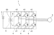
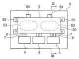
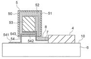
図1は、この発明の実施の形態1による電力変換装置を示す回路図である。また、図2は、図1の電力変換装置を示す上面図である。さらに、図3は、図2のIII−III線に沿った断面図である。電力変換装置1は、電源と負荷との間で電気エネルギを変換する装置である。この例では、ハイブリッド自動車、電気自動車などの車両に搭載される車両用電力変換装置が電力変換装置1として用いられている。
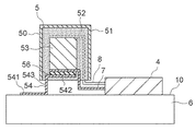
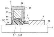
図4は、この発明の実施の形態2による電力変換装置を示す断面図である。N側バスバー7と取付部542との間には、充填部材52とは異なる絶縁部材としての絶縁紙56が介在している。これにより、熱伝導部材54の取付部542は、コンデンサケース51の内部で絶縁紙56を介してN側バスバー7に配置されている。絶縁紙56の熱伝導率は、充填部材52の熱伝導率よりも高くなっている。また、絶縁紙56は、電気絶縁性能を持つ絶縁部材である。絶縁紙56の電気絶縁性能は、充填部材52の電気絶縁性能よりも高くなっている。
図5は、この発明の実施の形態3による電力変換装置を示す断面図である。コンデンサモジュール本体50と冷却面10との間には、断熱部材57が介在している。また、コンデンサモジュール本体50は、断熱部材57を介して冷却面10に支持されている。
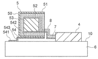
図6は、この発明の実施の形態4による電力変換装置を示す断面図である。熱伝導部材54の取付部542は、コンデンサモジュール本体50の外面に取り付けられている。また、取付部542は、コンデンサモジュール本体50の外面に接触している。取付部542は、コンデンサモジュール本体50の外面に接触することによりコンデンサモジュール本体50の外面に熱的に接続されている。この例では、コンデンサケース51の外面に取付部542が接触している。従って、この例では、熱伝導部材54がコンデンサモジュール本体50の内部に挿入されていない。
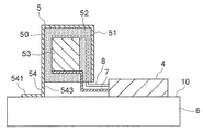
図7は、この発明の実施の形態5による電力変換装置を示す断面図である。熱伝導部材54は、コンデンサケース51と一体に形成されている。また、コンデンサケース51は、熱伝導部材54と同じ材料で構成されている。即ち、同じ材料で構成された単一部材の一部がコンデンサケース51になっており、単一部材の残りの部分が熱伝導部材54になっている。コンデンサケース51及び熱伝導部材54を構成する材料としては、高い熱伝導性能を持つアルミニウムなどの金属が用いられている。コンデンサケース51及び熱伝導部材54が一体となった部材の熱伝導率は、充填部材52の熱伝導率よりも高くなっている。
Claims (10)
- 冷却面が形成された冷却器、
前記冷却面に設けられた半導体モジュール、及び
前記冷却面から離れた状態で前記冷却面に対向しているコンデンサモジュール本体と、前記コンデンサモジュール本体に設けられた熱伝導部材とを有するコンデンサモジュール
を備え、
前記コンデンサモジュール本体は、前記半導体モジュールにバスバーを介して接続されており、
前記熱伝導部材は、放熱部を有しており、
前記放熱部は、前記コンデンサモジュール本体の前記半導体モジュール側の端部よりも前記半導体モジュールから遠い位置で前記冷却面に熱的に接続されている電力変換装置。 - 前記冷却面は、前記冷却器を流れる冷却媒体によって冷却されるようになっており、
前記放熱部は、前記冷却媒体の流れにおいて前記半導体モジュールの位置よりも上流側の位置で前記冷却面に熱的に接続されている請求項1に記載の電力変換装置。 - 前記コンデンサモジュール本体と前記冷却面との間には、前記コンデンサモジュール本体よりも熱伝導率の低い材料で構成された断熱部材が介在している請求項1又は請求項2に記載の電力変換装置。
- 前記熱伝導部材は、前記コンデンサモジュール本体の内部に配置された取付部を有している請求項1から請求項3のいずれか一項に記載の電力変換装置。
- 前記熱伝導部材は、前記コンデンサモジュール本体の外面に接触した取付部を有している請求項1から請求項3のいずれか一項に記載の電力変換装置。
- 前記熱伝導部材は、熱伝導性能を持つ密着部材を介して前記コンデンサモジュール本体の外面に取り付けられた取付部を有しており、
前記密着部材は、前記コンデンサモジュール本体の外面及び前記取付部のそれぞれに密着している請求項1から請求項3のいずれか一項に記載の電力変換装置。 - 前記コンデンサモジュール本体は、コンデンサケースと、前記コンデンサケースの内部に配置されたコンデンサ素子と、前記コンデンサケースの内部で前記コンデンサ素子を覆う樹脂製の充填部材とを有しており、
前記バスバーは、前記充填部材を貫通して前記コンデンサ素子に接続されており、かつ前記充填部材を介して前記コンデンサケースに保持されている請求項1から請求項3のいずれか一項に記載の電力変換装置。 - 前記コンデンサケースは、前記熱伝導部材と同じ材料で構成されており、
前記熱伝導部材は、前記コンデンサケースと一体に形成されている請求項7に記載の電力変換装置。 - 前記コンデンサ素子及び前記バスバーの少なくともいずれかと前記コンデンサケースとの間には、前記充填部材よりも熱伝導率の高い絶縁部材が介在している請求項8に記載の電力変換装置。
- 前記熱伝導部材は、前記充填部材の内部に配置された取付部を有しており、
前記コンデンサ素子及び前記バスバーの少なくともいずれかと前記取付部との間には、前記充填部材よりも熱伝導率の高い絶縁部材が介在している請求項7に記載の電力変換装置。
Priority Applications (4)
| Application Number | Priority Date | Filing Date | Title |
|---|---|---|---|
| JP2019088746A JP6867432B2 (ja) | 2019-05-09 | 2019-05-09 | 電力変換装置 |
| US16/830,511 US11622478B2 (en) | 2019-05-09 | 2020-03-26 | Power converter having improved cooling |
| CN202010331580.8A CN111917311A (zh) | 2019-05-09 | 2020-04-24 | 功率转换装置 |
| DE102020205236.0A DE102020205236B4 (de) | 2019-05-09 | 2020-04-24 | Leistungswandler |
Applications Claiming Priority (1)
| Application Number | Priority Date | Filing Date | Title |
|---|---|---|---|
| JP2019088746A JP6867432B2 (ja) | 2019-05-09 | 2019-05-09 | 電力変換装置 |
Publications (2)
| Publication Number | Publication Date |
|---|---|
| JP2020184847A true JP2020184847A (ja) | 2020-11-12 |
| JP6867432B2 JP6867432B2 (ja) | 2021-04-28 |
Family
ID=72943368
Family Applications (1)
| Application Number | Title | Priority Date | Filing Date |
|---|---|---|---|
| JP2019088746A Active JP6867432B2 (ja) | 2019-05-09 | 2019-05-09 | 電力変換装置 |
Country Status (4)
| Country | Link |
|---|---|
| US (1) | US11622478B2 (ja) |
| JP (1) | JP6867432B2 (ja) |
| CN (1) | CN111917311A (ja) |
| DE (1) | DE102020205236B4 (ja) |
Cited By (2)
| Publication number | Priority date | Publication date | Assignee | Title |
|---|---|---|---|---|
| JPWO2023162051A1 (ja) * | 2022-02-22 | 2023-08-31 | ||
| JP2023141447A (ja) * | 2022-03-24 | 2023-10-05 | 三菱電機株式会社 | 電力変換装置 |
Families Citing this family (5)
| Publication number | Priority date | Publication date | Assignee | Title |
|---|---|---|---|---|
| JP7366077B2 (ja) * | 2021-03-09 | 2023-10-20 | 三菱電機株式会社 | 電力変換装置 |
| JP7183373B1 (ja) * | 2021-11-15 | 2022-12-05 | 三菱電機株式会社 | 電力変換装置 |
| DE102022103760A1 (de) * | 2022-02-17 | 2023-08-17 | Tdk Electronics Ag | Kondensator, Verfahren zur Herstellung und Verwendung |
| JP7391134B2 (ja) * | 2022-04-19 | 2023-12-04 | 三菱電機株式会社 | 電力変換装置 |
| DE102022124194A1 (de) * | 2022-09-21 | 2024-03-21 | Valeo Eautomotive Germany Gmbh | Gleichspannungszwischenkreiskondensator für eine Schaltzelle |
Citations (10)
| Publication number | Priority date | Publication date | Assignee | Title |
|---|---|---|---|---|
| JP2001197753A (ja) * | 2000-01-13 | 2001-07-19 | Mitsubishi Electric Corp | 電力変換装置 |
| JP2008061476A (ja) * | 2006-09-04 | 2008-03-13 | Nissan Motor Co Ltd | 電力変換装置 |
| JP2008067546A (ja) * | 2006-09-08 | 2008-03-21 | Toyota Motor Corp | コンデンサの冷却構造およびその冷却構造を備えたモータ |
| JP2010187504A (ja) * | 2009-02-13 | 2010-08-26 | Mitsubishi Electric Corp | インバータ装置 |
| JP2012199350A (ja) * | 2011-03-22 | 2012-10-18 | Panasonic Corp | ケースモールド型コンデンサ |
| JP2013146179A (ja) * | 2011-12-13 | 2013-07-25 | Denso Corp | 電力変換装置 |
| JP2017108524A (ja) * | 2015-12-09 | 2017-06-15 | 富士電機株式会社 | 電力変換装置 |
| JP2017188998A (ja) * | 2016-04-05 | 2017-10-12 | 三菱電機株式会社 | 電力変換装置 |
| JP2018133889A (ja) * | 2017-02-14 | 2018-08-23 | 株式会社デンソー | 電力変換装置 |
| WO2019021532A1 (ja) * | 2017-07-28 | 2019-01-31 | 株式会社日立製作所 | 電力変換装置 |
Family Cites Families (15)
| Publication number | Priority date | Publication date | Assignee | Title |
|---|---|---|---|---|
| DE10056474B4 (de) * | 2000-11-15 | 2004-10-28 | Epcos Ag | Gehäuse, Gehäuseanordnung, Elektrolyt-Kondensator mit dem Gehäuse und Anordnung des Elektrolyt-Kondensators |
| JP4859443B2 (ja) | 2005-11-17 | 2012-01-25 | 日立オートモティブシステムズ株式会社 | 電力変換装置 |
| US7864506B2 (en) * | 2007-11-30 | 2011-01-04 | Hamilton Sundstrand Corporation | System and method of film capacitor cooling |
| JP5326760B2 (ja) * | 2009-04-14 | 2013-10-30 | 株式会社デンソー | 電力変換装置 |
| JP5550927B2 (ja) * | 2010-01-29 | 2014-07-16 | 本田技研工業株式会社 | 電力変換装置 |
| JP5351107B2 (ja) | 2010-07-23 | 2013-11-27 | 三菱電機株式会社 | コンデンサの冷却構造およびインバータ装置 |
| KR101541181B1 (ko) | 2014-05-16 | 2015-08-03 | 주식회사 이지트로닉스 | 전기자동차용 전력 변환 장치 |
| CN106663677B (zh) * | 2014-08-22 | 2019-07-16 | 三菱电机株式会社 | 电力变换装置 |
| US9756755B2 (en) * | 2014-10-31 | 2017-09-05 | Denso Corporation | Electric power converter |
| JP2016158358A (ja) * | 2015-02-24 | 2016-09-01 | 株式会社デンソー | 半導体モジュール |
| DE102015111541B4 (de) * | 2015-07-16 | 2023-07-20 | Halla Visteon Climate Control Corporation | Verfahren zur Herstellung einer Verbindung zwischen mindestens einem zylindrischen Elektrolytkondensator und einem Kühlkörper |
| WO2017072870A1 (ja) * | 2015-10-28 | 2017-05-04 | 三菱電機株式会社 | 電力変換装置 |
| JP6919348B2 (ja) * | 2017-06-07 | 2021-08-18 | 株式会社デンソー | 電力変換装置 |
| WO2019208406A1 (ja) * | 2018-04-25 | 2019-10-31 | 株式会社デンソー | 電力変換装置 |
| US11282640B2 (en) * | 2019-04-12 | 2022-03-22 | Karma Automotive Llc | DC link capacitor cooling system |
-
2019
- 2019-05-09 JP JP2019088746A patent/JP6867432B2/ja active Active
-
2020
- 2020-03-26 US US16/830,511 patent/US11622478B2/en active Active
- 2020-04-24 CN CN202010331580.8A patent/CN111917311A/zh not_active Withdrawn
- 2020-04-24 DE DE102020205236.0A patent/DE102020205236B4/de active Active
Patent Citations (10)
| Publication number | Priority date | Publication date | Assignee | Title |
|---|---|---|---|---|
| JP2001197753A (ja) * | 2000-01-13 | 2001-07-19 | Mitsubishi Electric Corp | 電力変換装置 |
| JP2008061476A (ja) * | 2006-09-04 | 2008-03-13 | Nissan Motor Co Ltd | 電力変換装置 |
| JP2008067546A (ja) * | 2006-09-08 | 2008-03-21 | Toyota Motor Corp | コンデンサの冷却構造およびその冷却構造を備えたモータ |
| JP2010187504A (ja) * | 2009-02-13 | 2010-08-26 | Mitsubishi Electric Corp | インバータ装置 |
| JP2012199350A (ja) * | 2011-03-22 | 2012-10-18 | Panasonic Corp | ケースモールド型コンデンサ |
| JP2013146179A (ja) * | 2011-12-13 | 2013-07-25 | Denso Corp | 電力変換装置 |
| JP2017108524A (ja) * | 2015-12-09 | 2017-06-15 | 富士電機株式会社 | 電力変換装置 |
| JP2017188998A (ja) * | 2016-04-05 | 2017-10-12 | 三菱電機株式会社 | 電力変換装置 |
| JP2018133889A (ja) * | 2017-02-14 | 2018-08-23 | 株式会社デンソー | 電力変換装置 |
| WO2019021532A1 (ja) * | 2017-07-28 | 2019-01-31 | 株式会社日立製作所 | 電力変換装置 |
Cited By (4)
| Publication number | Priority date | Publication date | Assignee | Title |
|---|---|---|---|---|
| JPWO2023162051A1 (ja) * | 2022-02-22 | 2023-08-31 | ||
| JP7767575B2 (ja) | 2022-02-22 | 2025-11-11 | Astemo株式会社 | 電力変換装置 |
| JP2023141447A (ja) * | 2022-03-24 | 2023-10-05 | 三菱電機株式会社 | 電力変換装置 |
| JP7370408B2 (ja) | 2022-03-24 | 2023-10-27 | 三菱電機株式会社 | 電力変換装置 |
Also Published As
| Publication number | Publication date |
|---|---|
| US11622478B2 (en) | 2023-04-04 |
| DE102020205236B4 (de) | 2025-11-27 |
| US20200359533A1 (en) | 2020-11-12 |
| JP6867432B2 (ja) | 2021-04-28 |
| CN111917311A (zh) | 2020-11-10 |
| DE102020205236A1 (de) | 2020-11-12 |
Similar Documents
| Publication | Publication Date | Title |
|---|---|---|
| JP6867432B2 (ja) | 電力変換装置 | |
| JP6932225B1 (ja) | 電力変換装置 | |
| KR102786035B1 (ko) | 차량, 및 차량용 전력 변환 장치 | |
| JP6887521B2 (ja) | 電力変換装置 | |
| US11956933B2 (en) | Power conversion device and motor-integrated power conversion device | |
| KR102801834B1 (ko) | 냉각 장치를 구비한 펄스 제어 인버터 및 펄스 제어 인버터를 구비한 자동차 | |
| US12249922B2 (en) | Power conversion device | |
| JP7366082B2 (ja) | 電力変換装置 | |
| CN113728546A (zh) | 电力转换装置 | |
| CA3063005A1 (en) | Cooling structure of power conversion device | |
| CN113965049B (zh) | 功率转换装置 | |
| JP5169092B2 (ja) | 電力変換装置 | |
| WO2019142543A1 (ja) | パワー半導体装置 | |
| CN112313869B (zh) | 电力转换装置 | |
| JP7234845B2 (ja) | コンデンサユニット | |
| CN215580872U (zh) | 电容模块、电力转换装置和车辆 | |
| WO2015140944A1 (ja) | パワーモジュール | |
| WO2025109770A1 (ja) | 電力変換装置 | |
| WO2025150090A1 (ja) | 電子機器、およびこの電子機器を備えた電動駆動装置 | |
| CN115528906A (zh) | 功率转换装置 |
Legal Events
| Date | Code | Title | Description |
|---|---|---|---|
| A621 | Written request for application examination |
Free format text: JAPANESE INTERMEDIATE CODE: A621 Effective date: 20190509 |
|
| A131 | Notification of reasons for refusal |
Free format text: JAPANESE INTERMEDIATE CODE: A131 Effective date: 20200519 |
|
| A131 | Notification of reasons for refusal |
Free format text: JAPANESE INTERMEDIATE CODE: A131 Effective date: 20200804 |
|
| A521 | Request for written amendment filed |
Free format text: JAPANESE INTERMEDIATE CODE: A523 Effective date: 20200925 |
|
| A02 | Decision of refusal |
Free format text: JAPANESE INTERMEDIATE CODE: A02 Effective date: 20201208 |
|
| A521 | Request for written amendment filed |
Free format text: JAPANESE INTERMEDIATE CODE: A523 Effective date: 20210302 |
|
| C60 | Trial request (containing other claim documents, opposition documents) |
Free format text: JAPANESE INTERMEDIATE CODE: C60 Effective date: 20210302 |
|
| A911 | Transfer to examiner for re-examination before appeal (zenchi) |
Free format text: JAPANESE INTERMEDIATE CODE: A911 Effective date: 20210315 |
|
| C21 | Notice of transfer of a case for reconsideration by examiners before appeal proceedings |
Free format text: JAPANESE INTERMEDIATE CODE: C21 Effective date: 20210316 |
|
| TRDD | Decision of grant or rejection written | ||
| A01 | Written decision to grant a patent or to grant a registration (utility model) |
Free format text: JAPANESE INTERMEDIATE CODE: A01 Effective date: 20210406 |
|
| A61 | First payment of annual fees (during grant procedure) |
Free format text: JAPANESE INTERMEDIATE CODE: A61 Effective date: 20210408 |
|
| R150 | Certificate of patent or registration of utility model |
Ref document number: 6867432 Country of ref document: JP Free format text: JAPANESE INTERMEDIATE CODE: R150 |
|
| R250 | Receipt of annual fees |
Free format text: JAPANESE INTERMEDIATE CODE: R250 |
|
| S111 | Request for change of ownership or part of ownership |
Free format text: JAPANESE INTERMEDIATE CODE: R313111 |
|
| R350 | Written notification of registration of transfer |
Free format text: JAPANESE INTERMEDIATE CODE: R350 |
|
| R250 | Receipt of annual fees |
Free format text: JAPANESE INTERMEDIATE CODE: R250 |
|
| R250 | Receipt of annual fees |
Free format text: JAPANESE INTERMEDIATE CODE: R250 |