JP2019166028A - Game machine - Google Patents
Game machine Download PDFInfo
- Publication number
- JP2019166028A JP2019166028A JP2018056054A JP2018056054A JP2019166028A JP 2019166028 A JP2019166028 A JP 2019166028A JP 2018056054 A JP2018056054 A JP 2018056054A JP 2018056054 A JP2018056054 A JP 2018056054A JP 2019166028 A JP2019166028 A JP 2019166028A
- Authority
- JP
- Japan
- Prior art keywords
- push button
- effect
- notice
- executed
- state
- Prior art date
- Legal status (The legal status is an assumption and is not a legal conclusion. Google has not performed a legal analysis and makes no representation as to the accuracy of the status listed.)
- Pending
Links
Images


Abstract
Description
本発明は、パチンコ遊技機等の遊技機に関する。 The present invention relates to a gaming machine such as a pachinko gaming machine.
遊技者が操作可能な操作ボタン及び操作レバーと、操作ボタン及び操作レバーの双方に振動を伝達可能な振動発生手段であるバイブレータと、を備える遊技機が提案されている(例えば特許文献1参照)。 A gaming machine has been proposed that includes an operation button and an operation lever that can be operated by a player, and a vibrator that is a vibration generating means capable of transmitting vibration to both the operation button and the operation lever (see, for example, Patent Document 1). .
特許文献1に記載されたような遊技機において、遊技者が操作手段に触れたときに操作手段が振動していることを好適に伝達できないおそれがあった。
In the gaming machine described in
この発明は、上記の実状に鑑みてなされたものであり、操作手段が振動していることを遊技者に好適に伝達できる遊技機を提供することを目的とする。 The present invention has been made in view of the above situation, and an object of the present invention is to provide a gaming machine capable of suitably transmitting to a player that the operating means is vibrating.
(1)上記目的を達成するため、本願発明に係る遊技機は、
遊技者に有利な有利状態(例えば大当り遊技状態)に制御可能な遊技機(例えばパチンコ遊技機1)であって、
遊技者が操作可能な操作手段(例えばプッシュボタン31B)と、
前記操作手段が操作されたことを検出する検出手段(例えばプッシュセンサ35B)と、
少なくとも前記操作手段を振動させることが可能な振動手段(例えば振動モータ304)と、を備え、
前記振動手段は、前記検出手段により操作が検出されているときは、前記検出手段により操作が検出されていないときよりも、前記操作手段を強く振動させる(例えば図16)。
このような構成によれば、好適に遊技者に振動を伝達することができる。
(1) In order to achieve the above object, a gaming machine according to the present invention provides:
A gaming machine (for example, pachinko gaming machine 1) that can be controlled to an advantageous state (for example, a big hit gaming state) advantageous to a player,
Operation means (for example,
Detecting means (for example,
Vibration means (for example, vibration motor 304) capable of vibrating at least the operation means,
The vibration means vibrates the operation means more strongly when the operation is detected by the detection means than when the operation is not detected by the detection means (for example, FIG. 16).
According to such a configuration, vibration can be suitably transmitted to the player.
(2)上記(1)の遊技機において、
前記検出手段により操作が検出されたことに基づいて演出態様を変化可能な操作演出(例えばボタン予告)を実行可能であり、
前記検出手段により操作が検出されていないときに前記操作手段が振動した場合、その後に前記操作演出が実行される場合と前記操作演出が実行されない場合とがある(ボタン予告示唆が実行された後にボタン予告が実行される場合と実行されない場合ある。また、変動開始時振動予告のようにその後にプッシュボタン31Bを操作させる演出を伴わずに振動する場合がある)ようにしてもよい。
このような構成によれば、操作手段が振動した後に操作演出が実行されるか否かに注目させることができる。
(2) In the gaming machine of (1) above,
An operation effect (for example, a button notice) that can change the effect mode based on the operation detected by the detection means can be executed.
When the operation means vibrates when the operation is not detected by the detection means, the operation effect may be executed after that or the operation effect may not be executed (after the button notice suggestion is executed). There may be a case where the button notice is executed or a case where the button notice is not executed, and there may be a case where the button button vibrates without the effect of operating the
According to such a configuration, it can be noted whether or not the operation effect is executed after the operation means vibrates.
(3)上記(1)または(2)の遊技機において、
前記検出手段により操作が検出されたことに基づいて演出態様を変化可能な操作演出(例えばボタン予告)を実行可能であり、
前記操作演出が実行される場合と前記操作演出が実行されない場合とで、前記検出手段により操作が検出されていないときの前記操作手段の振動態様が異なる(例えばボタン予告示唆における振動パターンが異なる)ようにしてもよい。
このような構成によれば、振動態様によって操作演出の有無を示唆することができる。
(3) In the above gaming machine (1) or (2),
An operation effect (for example, a button notice) that can change the effect mode based on the operation detected by the detection means can be executed.
When the operation effect is executed and when the operation effect is not executed, the vibration mode of the operation unit when the operation is not detected by the detection unit is different (for example, the vibration pattern in the button notice suggestion is different). You may do it.
According to such a structure, the presence or absence of the operation effect can be suggested by the vibration mode.
(4)上記(1)から(3)のいずれかの遊技機において、
前記振動手段は、前記検出手段により操作が検出されているときであってその後に前記有利状態に制御される場合(当否煽りの大当り報知時)には、前記操作手段を他のタイミングより強く振動させる(振動強度が最強の振動パターンDで振動させる)ようにしてもよい。
このような構成によれば、振動態様によって有利状態に制御されることを報知でき、興趣が向上する。
(4) In any of the above gaming machines (1) to (3),
The vibration means vibrates the operation means more strongly than other timings when the operation is detected by the detection means and is controlled to the advantageous state after that (when the hit / failure notification is made). (Vibration is performed with the vibration pattern D having the strongest vibration intensity).
According to such a structure, it can alert | report that it is controlled to an advantageous state by a vibration aspect, and an interest improves.
(5)上記(1)から(4)のいずれかの遊技機において、
前記操作手段は、前記操作手段の振動の強度を切り替えるときに、一旦振動を停止させてから振動の強度を切り替える(例えば図16(E))ようにしてもよい。
このような構成によれば、振動の強度が切り替わったことがわかりやすくなる。
(5) In any of the above gaming machines (1) to (4),
When switching the vibration intensity of the operation means, the operation means may stop the vibration and then switch the vibration intensity (for example, FIG. 16E).
According to such a configuration, it becomes easy to understand that the intensity of vibration has been switched.
(6)上記(1)から(5)のいずれかの遊技機において、
前記振動手段による振動が特定部材(例えば各種基板や他の部材)に伝達しにくくするための緩衝手段(ゴムやゲル等の緩衝部材)をさらに備えるようにしてもよい。
このような構成によれば、振動による特定部材への影響を低減できる。
(6) In any of the above gaming machines (1) to (5),
You may make it further provide the buffer means (buffer members, such as rubber | gum and gel) for making it difficult to transmit the vibration by the said vibration means to a specific member (for example, various board | substrates and other members).
According to such a structure, the influence on the specific member by vibration can be reduced.
(7)上記(1)から(6)のいずれかの遊技機において、
遊技者に対して前記操作手段の操作を促すための画像であって、前記操作手段に対応する操作手段対応画像である第1操作手段対応画像(例えば、非突出状態のプッシュボタン31Bの画像)または該第1操作手段対応画像とは異なる第2操作手段対応画像(例えば、突出状態のプッシュボタン31Bの画像)を表示可能な表示手段(例えば演出表示装置5)と、をさらに備え、
前記第1操作手段対応画像の表示中に前記操作手段が操作された場合には、該操作から第1期間が経過したことに基づいて前記第1操作手段対応画像の表示を終了し(例えば、図22(A)に示すように、操作促進画像として非突出状態のプッシュボタン31Bの画像の表示中にプッシュボタン31Bが操作された場合には、該操作から期間L2が経過したタイミングでプッシュボタン31Bの画像を消去する部分)、
前記第2操作手段対応画像の表示中に前記操作手段が操作された場合には、該操作から前記第1期間とは異なる第2期間が経過したことに基づいて前記第2操作手段対応画像の表示を終了する(例えば、図22(B)に示すように、操作促進画像として突出状態のプッシュボタン31Bの画像の表示中にプッシュボタン31Bが操作された場合には、該操作から期間L3が経過したタイミングでプッシュボタン31Bの画像を消去する部分)ようにしてもよい。
このような構成によれば、表示される操作手段対応画像に応じて操作手段が操作されてから操作手段対応画像の表示が終了されるまでの期間を異ならせることにより、遊技興趣を向上できる。
(7) In any of the above gaming machines (1) to (6),
An image for prompting the player to operate the operation means, and an image corresponding to the first operation means corresponding to the operation means (for example, an image of the
When the operation means is operated during the display of the first operation means corresponding image, the display of the first operation means corresponding image is ended based on the elapse of the first period from the operation (for example, As shown in FIG. 22A, when the
When the operation means is operated during the display of the second operation means corresponding image, the second operation means corresponding image is determined based on the fact that a second period different from the first period has elapsed since the operation. The display is terminated (for example, as shown in FIG. 22B, when the
According to such a configuration, it is possible to improve the game entertainment by changing the period from when the operation unit is operated according to the displayed operation unit corresponding image until the display of the operation unit corresponding image is ended.
本発明に係る遊技機を実施するための形態を実施例に基づいて以下に説明する。 A mode for carrying out a gaming machine according to the present invention will be described below based on examples.
まず、遊技機の一例であるパチンコ遊技機1の全体の構成について説明する。尚、以下の説明にて、図1の手前側をパチンコ遊技機1の前方(前面、正面)側、奥側を後方(背面)側として説明する。尚、本実施例でパチンコ遊技機1の前面とは、遊技者側からパチンコ遊技機1を見たときに該遊技者と対向する対向面である。尚、フローチャートの各ステップの説明にて、例えば「ステップS1」と記載する箇所を「S1」と略記する場合がある。また、本実施例で『実行』と『実施』とは同義である。
First, the overall configuration of a
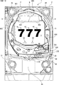
図1は、本実施例のパチンコ遊技機1の正面図であり、主要部材の配置レイアウトを示す。パチンコ遊技機1(以下、遊技機と略記する場合がある)は、大別して、遊技盤面を構成する遊技盤2(ゲージ盤)と、遊技盤2を支持固定する遊技機用枠3(台枠)とから構成されている。遊技盤2には、ガイドレールによって囲まれた、ほぼ円形状の遊技領域が形成されている。遊技領域には、遊技球が打球発射装置から発射されて打ち込まれる。
FIG. 1 is a front view of a
遊技盤2の所定位置(図1に示す例では、遊技領域の右側方)には、第1特別図柄表示器4Aと、第2特別図柄表示器4Bとが設けられている。第1特別図柄表示器4Aと第2特別図柄表示器4Bはそれぞれ、例えば7セグメントやドットマトリクスのLED(発光ダイオード)等から構成され、変動表示ゲームの一例となる特図ゲームにて、各々を識別可能な複数種類の識別情報(特別識別情報)である特別図柄(「特図」ともいう)が、変動可能に表示(変動表示または可変表示ともいう)される。例えば、第1特別図柄表示器4Aと第2特別図柄表示器4Bはそれぞれ、「0」〜「9」を示す数字や「−」を示す記号等から構成される複数種類の特別図柄を変動表示する。尚、第1特別図柄表示器4Aや第2特別図柄表示器4Bにて表示される特別図柄は、「0」〜「9」を示す数字や「−」を示す記号等から構成されるものに限定されず、例えば7セグメントのLEDで点灯させるものと消灯させるものとの組合せを異ならせた複数種類の点灯パターンが、複数種類の特別図柄として予め設定されていればよい。以下では、第1特別図柄表示器4Aにて変動表示される特別図柄を「第1特図」ともいい、第2特別図柄表示器4Bにて変動表示される特別図柄を「第2特図」ともいう。
A first
第1特別図柄表示器4Aと第2特別図柄表示器4Bはともに、例えば方形状に形成されている。尚、第1特図の種類と第2特図の種類は同じ(例えば、ともに「0」〜「9」を示す数字、及び、「−」を示す記号)であってもよいし、種類が異なっていてもよい。また、第1特別図柄表示器4Aと第2特別図柄表示器4Bはそれぞれ、例えば「00」〜「99」を示す数字(あるいは2桁の記号)を変動表示するように構成されていてもよいし、これら「00」〜「99」を示す各セグメントが、「00」〜「99」を視認不能にランダムに配置された表示器により変動表示するように構成されていてもよい。
Both the first
遊技盤2の遊技領域の中央付近には、演出表示装置5が設けられている。演出表示装置5は、例えばLCD(液晶表示装置)等から構成され、各種の演出画像を表示する表示領域を形成している。演出表示装置5の表示領域では、第1特別図柄表示器4Aによる第1特図の変動表示や第2特別図柄表示器4Bによる第2特図の変動表示のそれぞれに対応して、例えば3つといった複数の変動表示部となる演出図柄表示エリアにて、各々を識別可能な複数種類の識別情報(装飾識別情報)である演出図柄(飾り図柄ともいう)が変動表示される。この演出図柄の変動表示も、変動表示ゲームに含まれる。
An
一例として、演出表示装置5の表示領域には、「左」、「中」、「右」の演出図柄表示エリア5L,5C,5Rが配置されている。そして、第1特別図柄表示器4Aでの第1特図の変動と第2特別図柄表示器4Bでの第2特図の変動のうち、いずれかが開始されることに対応して、「左」、「中」、「右」の各演出図柄表示エリア5L,5C,5Rにて演出図柄の変動(例えば上下方向のスクロール表示)が開始される。その後、演出表示装置5の「左」、「中」、「右」の各演出図柄表示エリア5L,5C,5Rにて、確定演出図柄(最終停止図柄)が停止表示される。
As an example, in the display area of the
このように、演出表示装置5の表示領域では、第1特別図柄表示器4Aでの第1特図を用いた特図ゲーム、または、第2特別図柄表示器4Bでの第2特図を用いた特図ゲームと同期して、各々が識別可能な複数種類の演出図柄の変動表示を行い、確定演出図柄を導出表示(あるいは単に「導出」ともいう)する。尚、演出図柄の変動表示中に変動表示が仮停止するようにしても良い。
As described above, in the display area of the
「左」、「中」、「右」の各演出図柄表示エリア5L,5C,5Rにて変動表示される演出図柄には、例えば8種類の図柄(英数字「1」〜「8」あるいは漢数字や、英文字、所定のモチーフに関連する8個のキャラクタ画像、数字や文字あるいは記号とキャラクタ画像との組合せなどであればよく、キャラクタ画像は、例えば人物や動物、これら以外の物体、もしくは、文字などの記号、あるいは、その他の任意の図形を示す飾り画像であればよい)で構成される。演出図柄のそれぞれには、対応する図柄番号が付されている。例えば、「1」〜「8」を示す英数字それぞれに対して、「1」〜「8」の図柄番号が付されている。尚、演出図柄は8種類に限定されず、「大当り」となる組合せや「はずれ」となる組合せなど適当な数の組合せを構成可能であれば、何種類であってもよい(例えば7種類や9種類など)。
For example, eight kinds of symbols (alphanumeric characters “1” to “8” or Chinese characters) are displayed in the “left”, “middle”, and “right” effect
演出図柄の変動表示が開始された後、確定演出図柄が導出表示されるまでには、「左」、「中」、「右」の各演出図柄表示エリア5L,5C,5R、又は、演出図柄表示エリア5L,5C,5Rのうち少なくともいずれか1つ(例えば「左」の演出図柄表示エリア5Lなど)にて、例えば図柄番号が小さいものから大きいものへと順次に上方から下方へと流れるようなスクロール表示が行われ、図柄番号が最大(例えば「8」)である演出図柄が表示されると、続いて図柄番号が最小(例えば「1」)である演出図柄が表示される。
From the start of the variation display of the effect symbols, until the finalized effect symbols are derived and displayed, the “left”, “middle”, and “right” effect
演出表示装置5の表示領域の下部の左右2箇所には、第1保留記憶表示エリア5D、第2保留記憶表示エリア5Uが設定されている。第1保留記憶表示エリア5D、第2保留記憶表示エリア5Uでは、特図ゲームに対応した変動表示の保留記憶数(特図保留記憶数)を特定可能に表示する保留記憶表示が行われる。
A first reserved
ここで、特図ゲームに対応した変動表示の保留は、普通入賞球装置6Aが形成する第1始動入賞口や、普通可変入賞球装置6Bが形成する第2始動入賞口を、遊技球が通過(進入)することによる始動入賞に基づいて発生する。即ち、特図ゲームや演出図柄の変動表示といった変動表示ゲームを実行するための始動条件(「実行条件」ともいう)は成立したが、先に成立した開始条件に基づく変動表示ゲームが実行中であることやパチンコ遊技機1が大当り遊技状態(有利状態)に制御されていることなどにより、変動表示ゲームの開始を許容する開始条件が成立していないときに、成立した始動条件に対応する変動表示の保留が行われる。本実施例では、第1始動入賞口を遊技球が通過(進入)することによる始動入賞に基づいて発生した保留記憶表示と第2始動入賞口を遊技球が通過(進入)することによる始動入賞に基づいて発生した保留記憶表示とを丸型の白色表示とする。
Here, the suspension of the variable display corresponding to the special game is that the game ball passes through the first start winning opening formed by the normal
尚、以下の説明では、第1保留記憶表示エリア5D、第2保留記憶表示エリア5Uでの表示を保留表示と総称することがある。
In the following description, the display in the first hold
図1に示す例では、保留記憶表示エリアとともに、第1特別図柄表示器4A及び第2特別図柄表示器4Bの上部と下部に、特図保留記憶数を特定可能に表示するための第1保留表示器25Aと第2保留表示器25Bとが設けられている。第1保留表示器25Aは、第1特図保留記憶数を特定可能に表示する。第2保留表示器25Bは、第2特図保留記憶数を特定可能に表示する。第1特図保留記憶数と第2特図保留記憶数とを加算した変動表示の保留記憶数は、特に、合計保留記憶数ともいう。
In the example shown in FIG. 1, the first hold for displaying the number of special figure hold memories in an identifiable manner on the upper and lower parts of the first
演出表示装置5の下方には、普通入賞球装置6Aと、普通可変入賞球装置6Bとが設けられている。普通入賞球装置6Aは、例えば所定の玉受部材によって常に一定の開放状態に保たれる第1始動入賞口を形成する。普通可変入賞球装置6Bは、図2に示す普通電動役物用となるソレノイド81によって、垂直位置となる通常開放状態と傾動位置となる拡大開放状態とに変化する一対の可動翼片を有する電動チューリップ型役物(普通電動役物)を備え、第2始動入賞口を形成する。
Below the
一例として、普通可変入賞球装置6Bでは、普通電動役物用のソレノイド81がオフ状態であるときに可動翼片が垂直位置となることにより、遊技球が第2始動入賞口を通過(進入)しがたい通常開放状態となる。その一方で、普通可変入賞球装置6Bでは、普通電動役物用のソレノイド81がオン状態であるときに可動翼片が傾動位置となる傾動制御により、遊技球が第2始動入賞口を通過(進入)しやすい拡大開放状態となる。尚、普通可変入賞球装置6Bは、通常開放状態であるときでも、第2始動入賞口には遊技球が進入可能であるものの、拡大開放状態であるときよりも遊技球が進入する可能性が低くなるように構成してもよい。あるいは、普通可変入賞球装置6Bは、通常開放状態にて、例えば第2始動入賞口を閉鎖することなどにより、第2始動入賞口には遊技球が進入しないように構成してもよい。このように、第2始動入賞口は、遊技球が通過(進入)しやすい拡大開放状態と、遊技球が通過(進入)しにくいまたは通過(進入)できない通常開放状態とに変化する。
As an example, in the normally variable winning
普通入賞球装置6Aに形成された第1始動入賞口を通過(進入)した遊技球は、例えば図2に示す第1始動口スイッチ22Aによって検出される。普通可変入賞球装置6Bに形成された第2始動入賞口を通過(進入)した遊技球は、例えば図2に示す第2始動口スイッチ22Bによって検出される。第1始動口スイッチ22Aによって遊技球が検出されたことに基づき、所定個数(例えば3個)の遊技球が賞球として払い出され、第1特図保留記憶数が所定の上限値(例えば「4」)未満であれば、第1始動条件が成立する。第2始動口スイッチ22Bによって遊技球が検出されたことに基づき、所定個数(例えば3個)の遊技球が賞球として払い出され、第2特図保留記憶数が所定の上限値(例えば「4」)未満であれば、第2始動条件が成立する。尚、第1始動口スイッチ22Aによって遊技球が検出されたことに基づいて払い出される賞球の個数と、第2始動口スイッチ22Bによって遊技球が検出されたことに基づいて払い出される賞球の個数は、互いに同一の個数であってもよいし、異なる個数であってもよい。
A game ball that has passed (entered) the first start winning opening formed in the normal
普通入賞球装置6Aと普通可変入賞球装置6Bの下方位置には、特別可変入賞球装置7が設けられている。特別可変入賞球装置7は、図2に示す大入賞口扉用となるソレノイド82によって開閉駆動される大入賞口扉を備え、その大入賞口扉によって開放状態と閉鎖状態とに変化する所定領域としての大入賞口を形成する。
A special variable winning
一例として、特別可変入賞球装置7では、大入賞口扉用のソレノイド82がオフ状態であるときに大入賞口扉が大入賞口を閉鎖状態として、遊技球が大入賞口を通過(進入)できなくする。その一方で、特別可変入賞球装置7では、大入賞口扉用のソレノイド82がオン状態であるときに大入賞口扉が大入賞口を開放状態として、遊技球が大入賞口を通過(進入)し易くする。このように、大入賞口は、遊技球が通過(進入)し易く遊技者にとって有利な開放状態と、遊技球が通過(進入)できず遊技者にとって不利な閉鎖状態とに変化する。尚、遊技球が大入賞口を通過(進入)できない閉鎖状態に代えて、あるいは閉鎖状態の他に、遊技球が大入賞口を通過(進入)しにくい一部開放状態を設けてもよい。
As an example, in the special variable winning
大入賞口を通過(進入)した遊技球は、例えば図2に示すカウントスイッチ23によって検出される。カウントスイッチ23によって遊技球が検出されたことに基づき、所定個数(例えば15個)の遊技球が賞球として払い出される。こうして、開放状態となった特別可変入賞球装置7の大入賞口を遊技球が通過(進入)したときには、他の入賞口(例えば第1始動入賞口や第2始動入賞口)を遊技球が通過(進入)したときよりも多くの賞球が払い出される。従って、特別可変入賞球装置7の大入賞口が開放状態となれば、その大入賞口に遊技球が進入可能となり、遊技者にとって有利な第1状態となる。その一方で、特別可変入賞球装置7の大入賞口が閉鎖状態となれば、大入賞口に遊技球を通過(進入)させて賞球を得ることが不可能または困難になり、遊技者にとって不利な第2状態となる。
The game ball that has passed (entered) through the big prize opening is detected by, for example, the
また、演出表示装置5の上方には、可動役物400が設けられている。該可動役物400は、可動役物第1駆動モータ301(図2参照)の駆動と図示しない駆動機構によって図1に示す演出表示装置5の上方位置である退避位置と、該退避位置よりも下方であり、パチンコ遊技機1の正面視において演出表示装置5と重畳する演出位置と、の間で垂直移動可能となっている。
A
更に、図1に示すように、可動役物400の左部には第1可動部401が配置されており、可動役物400の右部には第2可動部402が配置されている。第1可動部401は、可動役物400の左右幅方向における中央左部と左端部との間で移動可能に設けられており、第2可動部402は、可動役物400の左右幅方向における中央右部と右端部との間で移動可能に設けられている。特に本実施例の可動役物400は、可動役物第2駆動モータ302(図2参照)の駆動と図示しない駆動機構によって第1可動部401と第2可動部402とが連動して移動することによって、第1可動部401と第2可動部402とが左右幅方向の中央部で近接する近接状態(図1参照)と、第1可動部401と第2可動部402とがそれぞれ可動役物400の左端部と右端部とに移動して離間する離間状態(図25(J)参照)と、に変化可能となっている。尚、本実施例での可動役物400は、退避位置において近接状態にて配置され、演出位置に配置されることによって離間状態に変化するようになっている。
Further, as shown in FIG. 1, the first
遊技盤2の所定位置(図1に示す例では、遊技領域の下方)には、普通図柄表示器20が設けられている。一例として、普通図柄表示器20は、第1特別図柄表示器4Aや第2特別図柄表示器4Bと同様に7セグメントやドットマトリクスのLED等から構成され、特別図柄とは異なる複数種類の識別情報である普通図柄(「普図」あるいは「普通図」ともいう)を変動可能に表示(変動表示)する。このような普通図柄の変動表示は、普図ゲーム(「普通図ゲーム」ともいう)と称される。
A
普通図柄表示器20の側方には、普図保留表示器25Cが設けられている。普図保留表示器25Cは、例えば4個のLEDを含んで構成され、通過ゲート41を通過した有効通過球数としての普図保留記憶数を表示する。
On the side of the
遊技盤2の表面には、上記の構成以外にも、遊技球の流下方向や速度を変化させる風車及び多数の障害釘が設けられている。また、第1始動入賞口、第2始動入賞口及び大入賞口とは異なる入賞口として、例えば所定の玉受部材によって常に一定の開放状態に保たれる単一または複数の一般入賞口が設けられてもよい。この場合には、一般入賞口のいずれかに進入した遊技球が所定の一般入賞球スイッチによって検出されたことに基づき、所定個数(例えば10個)の遊技球が賞球として払い出されればよい。遊技領域の最下方には、いずれの入賞口にも進入しなかった遊技球が取り込まれるアウト口が設けられている。
In addition to the above-described configuration, the surface of the
遊技機用枠3の左右上部位置には、効果音等を再生出力するためのスピーカ8L,8Rが設けられており、更に遊技領域周辺部には、演出用LED9が設けられている。
遊技機用枠3の右下部位置には、遊技球を遊技領域に向けて発射するために遊技者等によって操作される打球操作ハンドル(操作ノブ)が設けられている。例えば、打球操作ハンドルは、遊技者等による操作量(回転量)に応じて遊技球の弾発力を調整する。打球操作ハンドルには、打球発射装置が備える発射モータの駆動を停止させるための単発発射スイッチや、タッチリング(タッチセンサ)が設けられていればよい。
In the lower right position of the
遊技領域下方の遊技機用枠3の所定位置には、賞球として払い出された遊技球や貸し出しによって払い出された遊技球を、打球発射装置へと供給可能に保持(貯留)する上皿(打球供給皿)が設けられている。遊技機用枠3の下部には、上皿から溢れた余剰球などを、パチンコ遊技機1の外部へと排出可能に保持(貯留)する下皿(図示略)が設けられている。
At a predetermined position of the
また、上皿には、遊技機の前方に膨出する膨出部30が形成されており、該膨出部30の上面には、遊技者が操作可能なプッシュボタン31Bが設けられている。本実施例のプッシュボタン31Bは、振動モータ304(図2参照)の駆動により、振動可能に構成されている。また、本実施例のプッシュボタン31Bは、ボタン駆動モータ303(図2参照)の駆動と図示しない駆動機構によって膨出部30内に収納されている非突出状態と該非突出状態よりも膨出部30の上方に向けて突出する突出状態とに変化可能に設けられており、遊技者は、これら非突出状態のプッシュボタン31Bと突出状態のプッシュボタン31Bとを操作可能となっている。プッシュボタン31Bは、遊技者からの押下動作を、機械的、電気的、あるいは、電磁的に、検出できるように構成されていればよい。プッシュボタン31Bの配置位置における上皿の本体内部などには、プッシュボタン31Bに対してなされた遊技者による押下動作を検出するが設けられていればよい。
The upper plate is formed with a bulging
パチンコ遊技機1には、例えば、図2に示すような主基板11、演出制御基板12、音声制御基板13、LED制御基板14といった、各種の制御基板が搭載されている。また、パチンコ遊技機1には、主基板11と演出制御基板12との間で伝送される各種の制御信号を中継するための中継基板15なども搭載されている。その他にも、遊技盤2などの背面には、例えば払出制御基板、情報端子基板、発射制御基板、インタフェース基板、電源基板などといった、各種の基板が配置されている。
The
主基板11は、メイン側の制御基板であり、パチンコ遊技機1での遊技の進行を制御するための各種回路が搭載されている。主基板11は、主として、特図ゲームにて用いる乱数の設定機能、所定位置に配設されたスイッチ等からの出力信号を入力可能とする機能、演出制御基板12などからなるサブ側の制御基板に宛てて、指令情報の一例となる制御コマンドを制御信号として出力して送信する機能、外部に各種情報を出力する機能などを備えている。また、主基板11は、第1特別図柄表示器4Aと第2特別図柄表示器4Bを構成する各LED(例えばセグメントLED)などの点灯/消灯制御を行って第1特図や第2特図の変動表示を制御することや、普通図柄表示器20の点灯/消灯/発色制御などを行って普通図柄表示器20による普通図柄の変動表示を制御することといった、所定の表示図柄の変動表示を制御する機能も備えている。
The main board 11 is a main-side control board on which various circuits for controlling the progress of the game in the
主基板11には、例えば遊技制御用マイクロコンピュータ100や、遊技球検出用の各種スイッチからの検出信号を取り込んで遊技制御用マイクロコンピュータ100に伝送するスイッチ回路110、遊技制御用マイクロコンピュータ100からのソレノイド駆動信号をソレノイド81,82に伝送するソレノイド回路111などが搭載されている。
The main board 11 includes, for example, a
演出制御基板12は、主基板11とは独立したサブ側の制御基板であり、中継基板15を介して主基板11から伝送された制御信号を受信して、演出表示装置5、スピーカ8L,8R及び演出用LED9といった演出用の電気部品による演出動作を制御するための各種回路が搭載されている。即ち、演出制御基板12は、演出表示装置5の表示動作や、可動役物400の動作、スピーカ8L,8Rからの音声出力動作の全部または一部、演出用LED9などの点灯/消灯動作の全部または一部といった、演出用の電気部品に所定の演出動作を実行させるための制御内容を決定する機能を備えている。尚、中継基板15を有しない構成としても良い。
The
音声制御基板13は、演出制御基板12とは別個に設けられた音声出力制御用の制御基板であり、演出制御基板12からの指令や制御データ(音番号や音量レベル等)などに基づき、スピーカ8L,8Rから音声を出力させるための音声信号処理を実行する処理回路などが搭載されている。LED制御基板14は、演出制御基板12とは別個に設けられたLED出力制御用の制御基板であり、演出制御基板12からの指令や制御データなどに基づき、演出用LED9などの点灯/消灯駆動を行うLEDドライバ回路などが搭載されている。
The
図2に示すように、主基板11には、ゲートスイッチ21、第1始動口スイッチ22A、第2始動口スイッチ22B、カウントスイッチ23からの検出信号を伝送する配線が接続されている。尚、ゲートスイッチ21、第1始動口スイッチ22A、第2始動口スイッチ22B、カウントスイッチ23は、例えばセンサと称されるものなどのように、遊技球を検出できる任意の構成を有するものであればよい。また、主基板11には、第1特別図柄表示器4A、第2特別図柄表示器4B、普通図柄表示器20、第1保留表示器25A、第2保留表示器25B、普図保留表示器25Cなどの表示制御を行うための指令信号を伝送する配線が接続されている。
As shown in FIG. 2, wiring for transmitting detection signals from the
主基板11から演出制御基板12に向けて伝送される制御信号は、中継基板15によって中継される。中継基板15を介して主基板11から演出制御基板12に対して伝送される制御コマンドは、例えば電気信号として送受信される演出制御コマンドである。
A control signal transmitted from the main board 11 toward the
図3は、本実施例で用いられる演出制御コマンドの内容の一例を示す説明図である。演出制御コマンドは、例えば2バイト構成であり、1バイト目はMODE(コマンドの分類)を示し、2バイト目はEXT(コマンドの種類)を表す。尚、図3に示されたコマンド形態は一例であって、他のコマンド形態を用いてもよい。ここで、XXHは不特定の16進数であることを示し、演出制御コマンドによる指示内容に応じた値であればよい。 FIG. 3 is an explanatory diagram showing an example of the contents of the effect control command used in the present embodiment. The effect control command has, for example, a 2-byte structure, and the first byte indicates MODE (command classification), and the second byte indicates EXT (command type). Note that the command form shown in FIG. 3 is an example, and other command forms may be used. Here, XXH indicates an unspecified hexadecimal number and may be a value corresponding to the instruction content by the effect control command.
コマンド8001Hは、第1特別図柄表示器4Aでの変動開始を指定する第1変動開始コマンドである。コマンド8002Hは、第2特別図柄表示器4Bでの変動開始を指定する第2変動開始コマンドである。コマンド81XXHは、変動パターン(変動時間)を指定する変動パターン指定コマンドであり、指定する変動パターンなどに応じて、異なるEXTデータが設定される。
The command 8001H is a first change start command that specifies the start of change in the first
コマンド8CXXHは、変動表示結果通知コマンドであり、変動表示結果を指定する演出制御コマンドである。尚、コマンド8C00Hは、「はずれ」となる旨の事前決定結果を示すコマンドである。コマンド8C01Hは、「大当り」で大当り種別が「確変大当りA」となる旨を通知するコマンドである。コマンド8C02Hは、「大当り」で大当り種別が「確変大当りB」となる旨を通知するコマンドである。コマンド8C03Hは、「大当り」で大当り種別が「非確変大当り」となる旨を通知するコマンドである。 The command 8CXXH is a change display result notification command, and is an effect control command for designating the change display result. Note that the command 8C00H is a command indicating a pre-determined result indicating that it is “off”. The command 8C01H is a command for notifying that the big hit type is “big hit big hit A”. The command 8C02H is a command for notifying that “big hit” is the big hit type and “probable big hit B”. The command 8C03H is a command for notifying that the big hit type is “big hit” and the big hit type is “non-probable big hit”.
コマンド8F00Hは、演出図柄の変動停止(確定)を指定する図柄確定コマンドである。コマンド95XXHは、その時点の遊技状態を指定する遊技状態指定コマンドである。 The command 8F00H is a symbol confirmation command for designating the stop of variation (determination) of the effect symbol. The command 95XXH is a gaming state designation command that designates the gaming state at that time.
コマンドA0XXHは、大当り遊技状態の開始を指定する大当り開始指定コマンド(「ファンファーレコマンド」ともいう)である。コマンドA1XXHは、大当り遊技状態にて、大入賞口が開放状態となったこと及び大入賞口が開放状態である期間であることを通知する大入賞口開放中通知コマンドである。コマンドA2XXHは、大当り遊技状態にて、大入賞口が開放状態から閉鎖状態となったこと及び大入賞口が閉鎖状態である期間であることを通知する大入賞口開放後通知コマンドである。コマンドA3XXHは、大当り遊技状態の終了を指定する大当り終了指定コマンドである。 The command A0XXH is a jackpot start designation command (also referred to as a “fanfare command”) that designates the start of a jackpot gaming state. The command A1XXH is a big prize opening open notification command for notifying that the big prize opening is in an open state and that the big prize opening is in an open state in the big hit gaming state. The command A2XXH is a notification command after opening the big prize opening notifying that the big prize opening has been changed from the open state to the closed state and that the big prize opening is in the closed state in the big hit gaming state. Command A3XXH is a jackpot end designation command for designating the end of the jackpot gaming state.
尚、大入賞口開放中通知コマンドや大入賞口開放後通知コマンドでは、例えば通常開放大当り状態や短期開放大当り状態のラウンドの実行回数(例えば「1」〜「16」または「1」〜「5」)に対応したEXTデータが設定される。 It should be noted that the notification command during the opening of the big prize opening or the notification command after the big prize opening is opened, for example, the number of rounds executed in the normal opening big hit state or the short-term opening big hit state (for example, “1” to “16” or “1” to “5”). EXT data corresponding to ")" is set.
コマンドB100Hは、普通入賞球装置6Aが形成する第1始動入賞口への入賞によって第1始動条件が成立したことを通知する第1始動口入賞指定コマンドである。コマンドB200Hは、普通可変入賞球装置6Bが形成する第2始動入賞口への入賞によって第2始動条件が成立したことを通知する第2始動口入賞指定コマンドである。
The command B100H is a first start port winning designation command for notifying that the first start condition has been established by winning a first start winning port formed by the normal
コマンドC1XXHは、第1特図保留記憶数を通知する第1保留記憶数通知コマンドである。コマンドC2XXHは、第2特図保留記憶数を通知する第2保留記憶数通知コマンドである。 The command C1XXH is a first reserved memory count notification command for notifying the first special figure reserved memory count. The command C2XXH is a second reserved memory number notification command for notifying the second special figure reserved memory number.
主基板11に搭載された遊技制御用マイクロコンピュータ100は、例えば1チップのマイクロコンピュータであり、遊技制御用のプログラムや固定データ等を記憶するROM101(Read Only Memory 101)と、遊技制御用のワークエリアを提供するRAM102(Random Access Memory 102)と、遊技制御用のプログラムを実行して制御動作を行うCPU103(Central Processing Unit 103)と、CPU103とは独立して乱数値を示す数値データの更新を行う乱数回路104と、I/O105(Input/Outputport 105)とを備えて構成される。
The
一例として、遊技制御用マイクロコンピュータ100では、CPU103がROM101から読み出したプログラムを実行することにより、遊技の進行を制御するための各種処理が実行される。
As an example, in the
主基板11では、図4に示すように、特図表示結果判定用の乱数値MR1、大当り種別判定用の乱数値MR2、変動パターン判定用の乱数値MR3、普図表示結果判定用の乱数値MR4等の各種乱数値の数値データが、カウント可能に制御される。尚、乱数回路104は、これらの乱数値MR1〜MR4の一部または全部を示す数値データをカウントできるものであればよく、乱数回路104にてカウントしない乱数値については、CPU103が、ソフトウェアによって各種の数値データを更新することでカウントするようにすればよい。
On the main board 11, as shown in FIG. 4, a random value MR1 for determining a special figure display result, a random value MR2 for determining a jackpot type, a random value MR3 for determining a variation pattern, and a random value for determining a normal display result Numerical data of various random values such as MR4 is controlled so as to be countable. The
図5は、本実施例の変動パターンを示している。本実施例では、図5に示すような複数の変動パターンが予め用意されている。具体的に、本実施例では、変動表示結果が「はずれ」となる場合のうち、演出図柄の変動表示態様が「非リーチ」である場合と「リーチ」である場合のそれぞれに対応して、また、変動表示結果が「大当り」となる場合などに対応して、複数の変動パターンが予め用意されている。 FIG. 5 shows the variation pattern of the present embodiment. In this embodiment, a plurality of variation patterns as shown in FIG. 5 are prepared in advance. Specifically, in the present embodiment, among the cases where the variation display result is “out of”, corresponding to each of the case where the variation display mode of the production symbol is “non-reach” and “reach”, A plurality of variation patterns are prepared in advance in response to a case where the variation display result is “big hit”.
変動表示結果が「大当り」である場合に対応した変動パターンである大当り変動パターンや、演出図柄の変動表示態様が「リーチ」である場合のリーチ変動パターンには、ノーマルリーチのリーチ演出が実行されるノーマルリーチ変動パターンと、スーパーリーチα、スーパーリーチβといったスーパーリーチのリーチ演出が実行されるスーパーリーチ変動パターンとがある。尚、本実施例では、ノーマルリーチ変動パターンを1種類のみしか設けていないが、本発明はこれに限定されるものではなく、スーパーリーチと同様に、ノーマルリーチα、ノーマルリーチβ、…のように、複数のノーマルリーチ変動パターンを設けても良い。また、スーパーリーチ変動パターンでも、スーパーリーチαやスーパーリーチβに加えてスーパーリーチγ…といった3以上のスーパーリーチ変動パターンを設けても良い。 The reach effect of normal reach is executed for the jackpot variation pattern, which is a variation pattern corresponding to the case where the variation display result is “big hit”, and the reach variation pattern when the variation display mode of the effect design is “reach”. There are a normal reach fluctuation pattern and a super reach fluctuation pattern in which a reach expression of super reach such as super reach α and super reach β is executed. In this embodiment, only one type of normal reach variation pattern is provided. However, the present invention is not limited to this, and a plurality of normal reach α, normal reach β,... The normal reach fluctuation pattern may be provided. Also, in the super reach variation pattern, three or more super reach variation patterns such as super reach γ... In addition to super reach α and super reach β may be provided.
図5に示すように、本実施例におけるノーマルリーチのリーチ演出が実行されるノーマルリーチ変動パターンの特図変動時間については、スーパーリーチ変動パターンであるスーパーリーチα、スーパーリーチβよりも短く設定されている。また、本実施例におけるスーパーリーチα、スーパーリーチβといったスーパーリーチのリーチ演出が実行されるスーパーリーチ変動パターンの特図変動時間については、スーパーリーチβのスーパーリーチ演出が実行される変動パターンの方が、スーパーリーチαのスーパーリーチ演出が実行される変動パターンよりも特図変動時間が長く設定されている。 As shown in FIG. 5, the special figure fluctuation time of the normal reach fluctuation pattern in which the reach effect of the normal reach in the present embodiment is executed is set shorter than the super reach α and super reach β that are the super reach fluctuation patterns. . In addition, regarding the special figure variation time of the super reach variation pattern in which super reach reach production such as super reach α and super reach β in this embodiment is performed, the variation pattern in which super reach β super reach production is performed. However, the special figure variation time is set longer than the variation pattern in which the super reach production of the super reach α is executed.
尚、本実施例では、前述したようにスーパーリーチβ、スーパーリーチα、ノーマルリーチの順に変動表示結果が「大当り」となる大当り期待度(大当り信頼度)が高くなるように設定されているため、ノーマルリーチ変動パターン及びスーパーリーチ変動パターンにおいては変動時間が長いほど大当り期待度(大当り信頼度)が高くなっている。また、本実施例では、大当りとなる場合に、必ずリーチ状態となってスーパーリーチβ、スーパーリーチα、ノーマルリーチのいずれかが実行されるようになっているが、本発明はこれに限定されるものではなく、非リーチの変動パターンでも大当りとなる場合があるようにしてもよい。 In the present embodiment, as described above, the big hit expectation (big hit reliability) is set so that the fluctuation display result is “big hit” in the order of super reach β, super reach α, and normal reach. In the normal reach variation pattern and the super reach variation pattern, the longer the variation time, the higher the big hit expectation (big hit reliability). Further, in this embodiment, when a big hit is made, the reach state is always set and any one of the super reach β, the super reach α, and the normal reach is executed, but the present invention is limited to this. It may be a big hit even with a non-reach fluctuation pattern.
図2に示す遊技制御用マイクロコンピュータ100が備えるROM101には、ゲーム制御用のプログラムの他にも、遊技の進行を制御するために用いられる各種の選択用データ、テーブルデータなどが格納されている。例えば、ROM101には、CPU103が各種の判定や決定、設定を行うために予め用意された複数の判定テーブルや設定テーブルなどを構成するデータが記憶されている。また、ROM101には、CPU103が主基板11から各種の制御コマンドとなる制御信号を送信するために用いられる複数のコマンドテーブルを構成するテーブルデータや、図5に示すような変動パターンを複数種類格納する変動パターンテーブルを構成するテーブルデータなどが、記憶されている。
In addition to the game control program, the
図6は、ROM101に記憶される表示結果判定テーブルの構成例を示している。本実施例では、表示結果判定テーブルとして、第1特図と第2特図とで共通の表示結果判定テーブルを用いているが、本発明はこれに限定されるものではなく、第1特図と第2特図とで個別の表示結果判定テーブルを用いるようにしても良い。
FIG. 6 shows a configuration example of a display result determination table stored in the
表示結果判定テーブルは、第1特別図柄表示器4Aや第2特別図柄表示器4Bの特図ゲームにおいて確定特別図柄が導出表示される前に、その変動表示結果を「大当り」として大当り遊技状態に制御するか否かを、乱数値MR1に基づいて決定するために参照されるテーブルである。
In the display result determination table, before the fixed special symbol is derived and displayed in the special symbol game of the first
本実施例の表示結果判定テーブルでは、遊技状態が通常状態または時短状態(低確状態)であるか、確変状態(高確状態)であるかに応じて、乱数値MR1と比較される数値(判定値)が、「大当り」や「はずれ」の特図表示結果に割り当てられている。 In the display result determination table of the present embodiment, a numerical value (compared to the random value MR1 depending on whether the gaming state is the normal state, the short time state (low probability state), or the probability variation state (high probability state) ( (Judgment value) is assigned to the special figure display result of “big hit” or “out of place”.
表示結果判定テーブルでは、特図表示結果を「大当り」として大当り遊技状態に制御するか否かの決定結果に対して判定用データが割り当てられている。具体的に、本実施例では、遊技状態が確変状態(高確状態)であるときに、通常状態または時短状態(低確状態)であるときよりも多くの判定値が、「大当り」の特図表示結果に割り当てられている。これにより、確変制御が行われる確変状態(高確状態)では、通常状態または時短状態(低確状態)であるときに特図表示結果を「大当り」として大当り遊技状態に制御すると決定される確率(本実施例では約1/300)に比べて、特図表示結果を「大当り」として大当り遊技状態に制御すると決定される確率が高くなる(本実施例では約1/30)。即ち、表示結果判定テーブルでは、遊技状態が確変状態(高確状態)であるときに、通常状態や時短状態であるときに比べて大当り遊技状態に制御すると決定される確率が高くなるように、判定用データが大当り遊技状態に制御するか否かの決定結果に割り当てられている。 In the display result determination table, determination data is assigned to a determination result as to whether or not to control the big hit gaming state with the special figure display result as “big hit”. Specifically, in the present embodiment, when the gaming state is the probability variation state (high probability state), more judgment values than the normal state or the short time state (low probability state) are characteristic of “big hit”. Assigned to diagram display results. With this, in the probability variation state (high probability state) in which probability variation control is performed, the probability that the special figure display result will be determined to be “big hit” and controlled to the big hit gaming state in the normal state or the short time state (low probability state) Compared to (about 1/300 in the present embodiment), the probability that the special figure display result is determined to be “big hit” and controlled to the big hit gaming state becomes higher (about 1/30 in the present embodiment). That is, in the display result determination table, when the gaming state is a probability change state (high probability state), the probability that it is determined to control to the big hit gaming state is higher than when the gaming state is a normal state or a short time state. The determination data is assigned to the determination result of whether or not to control the big hit gaming state.
尚、ROM101には、大当り遊技状態に制御すると決定されたときに、乱数値MR2に基づき、大当り種別を複数種類のいずれかに決定するために参照される大当り種別判定テーブルや、乱数値MR3に基づいて変動パターンを、前述した図5に示す変動パターンのいずれかに決定するための変動パターン判定テーブルも記憶されている。
In the
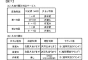
図7は、ROM101に記憶される大当り種別判定テーブルの構成例を示している。本実施例の大当り種別判定テーブルは、特図表示結果を「大当り」として大当り遊技状態に制御すると決定されたときに、大当り種別判定用の乱数値MR2に基づき、大当り種別を複数種類のいずれかに決定するために参照されるテーブルである。大当り種別判定テーブルでは、特図ゲームにおいて変動表示(変動)が行われた特別図柄が第1特図(第1特別図柄表示器4Aによる特図ゲーム)であるか第2特図(第2特別図柄表示器4Bによる特図ゲーム)であるかに応じて、大当り種別判定用の乱数値MR2と比較される数値(判定値)が、「非確変」や「確変大当りA」、「確変大当りB」といった複数種類の大当り種別に割り当てられている。
FIG. 7 shows a configuration example of the jackpot type determination table stored in the
ここで、本実施例における大当り種別について、図7(B)を用いて説明すると、本実施例では、大当り種別として、大当り遊技状態の終了後において高確制御と時短制御とが実行されて高確高ベース状態に移行する確変大当りAや確変大当りBと、大当り遊技状態の終了後において時短制御のみが実行されて低確高ベース状態に移行する非確変大当りとが設定されている。 Here, the jackpot type in this embodiment will be described with reference to FIG. 7B. In this embodiment, as the jackpot type, high-accuracy control and time-shortening control are executed after the jackpot gaming state is finished. The probability variation big hit A and the probability variation big hit B that shift to the accurate base state, and the non-probable big hit that shifts to the low accuracy high base state by executing only the time-shortening control after the big hit gaming state is set.
「確変大当りA」による大当り遊技状態と「非確変大当り」による大当り遊技状態では、前述したように、特別可変入賞球装置7を遊技者にとって有利な第1状態に変化させるラウンドが16回(いわゆる16ラウンド)、繰返し実行される通常開放大当りである。一方、「確変大当りB」による大当り遊技状態では、前述したように、特別可変入賞球装置7を遊技者にとって有利な第1状態に変化させるラウンドが5回(いわゆる5ラウンド)、繰返し実行される短期開放大当りである。よって、「確変大当りA」を16ラウンド(16R)確変大当りと呼称し、「確変大当りB」を5ラウンド(5R)確変大当りと呼称する場合がある。
In the big hit gaming state with “probable big hit A” and the big hit gaming state with “non-probable big hit”, as described above, there are 16 rounds of changing the special variable winning
確変大当りAや確変大当りBの大当り遊技状態の終了後において実行される高確制御と時短制御は、該大当り遊技状態の終了後において再度大当りが発生するまで継続して実行される。よって、再度発生した大当りが確変大当りAや確変大当りBである場合には、大当り遊技状態の終了後に再度、高確制御と時短制御が実行されるので、大当り遊技状態が通常状態を介することなく連続的に発生する、いわゆる連荘状態となる。 The high-accuracy control and the time-shortening control executed after the end of the big hit gaming state of the probability changing big hit A and the probability changing big hit B are continuously executed until the big hit occurs again after the end of the big hit gaming state. Therefore, when the big hit that has occurred again is the probable big hit A or the probable big hit B, the high-precision control and the short-time control are executed again after the big hit gaming state ends, so the big hit gaming state does not go through the normal state. It becomes a so-called consecutive resort state that occurs continuously.
一方、「非確変大当り」による大当り遊技状態の終了後において実行される時短制御は、所定回数(本実施例では100回)の特図ゲームが実行されること、或いは該所定回数の特図ゲームが実行される前に大当り遊技状態となることにより終了する。 On the other hand, the time-shortening control that is executed after the end of the big hit gaming state due to “non-probable big hit” is that a special number game is executed a predetermined number of times (in this embodiment, 100 times) or the predetermined number of special figure games is executed. The game is ended by being in a big hit gaming state before is executed.
図7(A)に示す大当り種別判定テーブルの設定例では、変動特図が第1特図であるか第2特図であるかに応じて、「確変大当りA」と「確変大当りB」の大当り種別に対する判定値の割当てが異なっている。即ち、変動特図が第1特図である場合には、所定範囲の判定値(「81」〜「100」の範囲の値)がラウンド数の少ない「確変大当りB」の大当り種別に割り当てられる一方で、変動特図が第2特図である場合には、「確変大当りB」の大当り種別に対して判定値が割り当てられていない。このような設定により、第1特別図柄表示器4Aによる第1特図を用いた特図ゲームを開始するための第1開始条件が成立したことに基づいて大当り種別を複数種類のいずれかに決定する場合と、第2特別図柄表示器4Bによる第2特図を用いた特図ゲームを開始するための第2開始条件が成立したことに基づいて大当り種別を複数種類のいずれかに決定する場合とで、大当り種別をラウンド数の少ない「確変大当りB」に決定する割合を、異ならせることができる。特に、第2特図を用いた特図ゲームでは大当り種別を「確変大当りB」としてラウンド数の少ない短期開放大当り状態に制御すると決定されることがないので、例えば時短制御に伴う高開放制御により、普通可変入賞球装置6Bが形成する第2始動入賞口に遊技球が進入しやすい遊技状態において、得られる賞球が少ない短期開放大当り状態の頻発を回避して遊技興趣が低下してしまうことを防止できるようになっている。
In the setting example of the big hit type determination table shown in FIG. 7 (A), “probable big hit A” and “probable big hit B” depend on whether the fluctuation special chart is the first special figure or the second special figure. Allocation of judgment value for jackpot type is different. That is, when the variation special chart is the first special chart, a predetermined range of determination values (values in the range of “81” to “100”) are assigned to the big hit type of “probability big hit B” with a small number of rounds. On the other hand, when the fluctuation special chart is the second special chart, the determination value is not assigned to the big hit type of “probability big hit B”. With such a setting, the jackpot type is determined to be one of a plurality of types based on the fact that the first start condition for starting the special figure game using the first special figure by the first
尚、図7(A)に示す大当り種別判定テーブルの設定例では、「非確変」の大当り種別に対する判定値の割当ては、変動特図が第1特図であるか第2特図であるかに係わらず同一とされているので、非確変の大当りとなる確率と確変の大当りとなる確率は、変動特図が第1特図であるか第2特図であるかにかかわらず同一とされている。 In the example of setting the jackpot type determination table shown in FIG. 7A, whether the variation special chart is the first special chart or the second special chart is assigned to the judgment value for the “non-probable variation” jackpot type. Regardless of whether the fluctuation special figure is the first special figure or the second special figure, the probability of being a non-probable big hit and the probability of being a probable big hit are the same. ing.
よって、上記したように、「確変大当りB」に対する判定値の割り当てが、変動特図が第1特図であるか第2特図であるかに応じて異なることに応じて、「確変大当りA」に対する判定値の割り当ても変動特図が第1特図であるか第2特図であるかに応じて異なり、ラウンド数の多い「確変大当りA」については、変動特図が第2特図である場合の方が第1特図である場合よりも決定され易くなるように設定されている。 Therefore, as described above, the allocation of the determination value to “probability variation big hit B” differs depending on whether the fluctuation special chart is the first special figure or the second special figure, and “probability big hit A” The allocation of the judgment value to "" differs depending on whether the fluctuation special chart is the first special figure or the second special figure, and for "probability big hit A" with a large number of rounds, the fluctuation special figure is the second special figure. It is set so that it is easier to determine the case of the case than the case of the first special drawing.
尚、変動特図が第2特図である場合にも、変動特図が第1特図である場合とは異なる所定範囲の判定値が、「確変大当りB」の大当り種別に割り当てられるようにしてもよい。例えば、変動特図が第2特図である場合には、変動特図が第1特図である場合に比べて少ない判定値が、「確変大当りB」の大当り種別に割り当てられてもよい。あるいは、変動特図が第1特図であるか第2特図であるかにかかわらず、共通のテーブルデータを参照して、大当り種別の決定を行うようにしてもよい。 Even when the fluctuation special chart is the second special figure, a predetermined range of judgment values different from those when the fluctuation special figure is the first special figure are assigned to the big hit type of “probability big hit B”. May be. For example, when the fluctuation special chart is the second special figure, a smaller judgment value than the case where the fluctuation special chart is the first special figure may be assigned to the big hit type of “probability big hit B”. Alternatively, regardless of whether the fluctuation special chart is the first special chart or the second special chart, the jackpot type may be determined with reference to the common table data.
また、ROM101に記憶されている変動パターン判定テーブルとしては、「大当り」とすることが事前決定されたときに使用される大当り用変動パターン判定テーブルと、「はずれ」にすることが事前決定されたときに使用されるはずれ用変動パターン判定テーブルとが予め用意されている。尚、本実施例では、はずれのときよりも大当りとなるときの方がリーチの変動パターンが決定されやすくなり、リーチが発生した場合の方が大当りになる可能性(信頼度や期待度)が高くなるとともに、同じリーチの変動パターンであっても、ノーマルリーチよりもスーパーリーチの方が大当りになる可能性(信頼度や期待度)が高く、同じスーパーリーチであってもスーパーリーチβの変動パターンの方が、確変大当りになる可能性(信頼度や期待度)が高くなるように、大当り用変動パターン判定テーブルとはずれ用変動パターン判定テーブルにおいて、各変動パターンに対応する判定値が設定されている。
The variation pattern determination table stored in the
尚、はずれ用変動パターン判定テーブルは、合計保留記憶数や時短状態に対応した複数のテーブルを含んでおり、保留記憶数や時短状態に応じて、合計保留記憶数が2〜4個に対応する短縮の非リーチはずれの変動パターン(PA1−2)や、合計保留記憶数が5〜8個に対応する短縮の非リーチはずれの変動パターン(PA1−3)や、短縮の非リーチはずれの変動パターン(PA1−4)を、合計保留記憶数や遊技状態(時短状態)に応じて決定することで、合計保留記憶数が多くなる程、短い変動パターンが実行され易い、つまり、単位時間当りの変動回数が高まることで、無駄な始動入賞の発生を防ぐことが可能であるとともに、時短制御中(時短状態中)では、時短制御が実行されていないときよりも、短縮の非リーチはずれの変動パターン(PA1−4)が多く決定されて単位時間当りの変動回数が高まることで、次の大当りまでの期間を短縮でき、遊技者の連荘感を向上できるようになっている。 The variation pattern determination table for loss includes a plurality of tables corresponding to the total number of reserved memories and the short time state, and the total number of reserved memories corresponds to 2 to 4 according to the number of reserved memories and the short time state. Short non-reach shift variation pattern (PA1-2), short non-reach shift variation pattern (PA1-3) corresponding to a total number of pending storages of 5 to 8, and short non-reach shift variation pattern By determining (PA1-4) according to the total number of reserved memories and the gaming state (short time state), the larger the total number of reserved memories, the easier the short variation pattern is executed, that is, the fluctuation per unit time By increasing the number of times, it is possible to prevent the occurrence of useless start winnings, and during non-time control (during short-time state), the non-reach deviation of the shortening changes more than when the time control is not executed. Pattern (PA1-4) that is often determined by increasing the number of times of the change per unit time, can reduce the time to the next jackpot, and to be able to improve the extended game player's sense of.
図2に示す遊技制御用マイクロコンピュータ100が備えるRAM102は、その一部または全部が所定の電源基板からのバックアップ電源によってバックアップされているバックアップRAMであればよい。すなわち、パチンコ遊技機1に対する電力供給が停止しても、所定期間(バックアップ電源としてのコンデンサが放電してバックアップ電源が電力供給不能になるまで)は、RAM102の一部または全部の内容は保存され、再度の電源投入にて、遊技状態すなわち遊技制御手段の制御状態に応じたデータ(特図プロセスフラグなど)と未払出賞球数を示すデータ等の遊技の進行状態を示すデータを引き継ぐようにすればよい。
The
このようなRAM102には、遊技の進行などを制御するために用いられる各種のデータを保持する領域として、図示しない遊技制御用データ保持エリアが設けられている。遊技制御用データ保持エリアは、普通入賞球装置6Aが形成する第1始動入賞口を遊技球が通過(進入)して始動入賞(第1始動入賞)が発生したものの未だ開始されていない第1特図を用いた特図ゲームの保留データとして、乱数値MR1、乱数値MR2、乱数値MR3を示す数値データなどを記憶する第1特図保留記憶部と、普通可変入賞球装置6Bが形成する第2始動入賞口を遊技球が通過(進入)して始動入賞(第2始動入賞)が発生したものの未だ開始されていない第2特図を用いた特図ゲームの保留データとして、乱数値MR1、乱数値MR2、乱数値MR3を示す数値データなどを記憶する第2特図保留記憶部と、普図保留記憶部と、特図プロセスフラグ等の遊技の進行状況などに応じて状態を更新可能な複数種類のフラグが設けられている遊技制御フラグ設定部と、遊技の進行を制御するために用いられる各種のタイマが設けられている遊技制御タイマ設定部と、遊技の進行を制御するために用いられるカウント値を計数するための複数種類のカウンタが設けられている遊技制御カウンタ設定部と、遊技の進行を制御するために用いられるデータを一時的に記憶する各種のバッファが設けられている遊技制御バッファ設定部と、を備えている。
In such a
図2に示すように、演出制御基板12には、プログラムに従って制御動作を行う演出制御用CPU120と、演出制御用のプログラムや固定データ等を記憶するROM121と、演出制御用CPU120のワークエリアを提供するRAM122と、演出表示装置5での表示動作の制御内容を決定するための処理などを実行する表示制御部123と、演出制御用CPU120とは独立して乱数値を示す数値データの更新を行う乱数回路124と、I/O125とが搭載されている。
As shown in FIG. 2, the
一例として、演出制御基板12では、演出制御用CPU120がROM121から読み出した演出制御用のプログラムを実行することにより、演出用の電気部品による演出動作を制御するための各種処理が実行される。例えば、これら演出動作を制御するための処理として、演出制御用CPU120がI/O125を介して演出制御基板12の外部から各種信号の入力を受け付ける受信処理、演出制御用CPU120がI/O125を介して演出制御基板12の外部へと各種信号を出力する送信処理なども行われる。
As an example, in the
尚、演出制御基板12の側でも、主基板11と同様に、例えば、各種演出の実行、非実行や、演出の種別等を決定するための各種の乱数値(演出用乱数ともいう)が設定されている。また、ROM121には、演出制御用のプログラムの他にも、可動役物400の演出動作を制御するために用いられる各種のテーブルデータ、例えば、各種演出の実行、非実行や、演出の種別等を決定するための複数の判定テーブルを構成するテーブルデータ、各変動パターンに対応する演出制御パターンを構成するパターンデータなどが記憶されている。
Note that, on the side of the
演出制御パターンのうち、特図変動時演出制御パターンは、各変動パターンに対応して、特別図柄の変動が開始されてから確定特別図柄が導出表示されるまでの期間における、演出図柄の変動表示動作や可動役物400を動作させるリーチ演出等の様々な演出動作の制御内容を示すデータなどから構成されている。
Among the effect control patterns, the effect control pattern at the time of special symbol variation displays the variation of the effect symbol during the period from the start of the variation of the special symbol until the finalized special symbol is derived and displayed corresponding to each variation pattern. It is comprised from the data etc. which show the control content of various production | presentation operation | movements, such as operation | movement and the reach production which operates the
また、RAM122には、演出動作を制御するために用いられる各種データを保持する領域として、例えば図示しない演出制御用データ保持エリアが設けられている。演出制御用データ保持エリアは、演出動作状態や主基板11から送信された演出制御コマンド等に応じて状態を更新可能な複数種類のフラグが設けられている演出制御フラグ設定部と、各種演出動作の進行を制御するために用いられる複数種類のタイマやカウンタが設けられている演出制御タイマ設定部や演出制御カウンタ設定部と、各種演出動作の進行を制御するために用いられるデータを一時的に記憶する各種のバッファが設けられている演出制御バッファ設定部とを備えている。
The
尚、本実施例では、演出制御バッファ設定部の所定領域に、第1特図保留記憶の合計保留記憶数の最大値(例えば「4」)に対応した格納領域(バッファ番号「1−1」〜「1−4」に対応した領域)と、第2特図保留記憶の合計保留記憶数の最大値(例えば「4」)に対応した格納領域(バッファ番号「2−1」〜「2−4」に対応した領域)が設けられ、その時点の保留記憶の状況を特定可能な保留記憶バッファを構成するデータが記憶されており、該保留記憶バッファのデータに基づいて、第1保留記憶表示エリア5Dと第2保留記憶表示エリア5Uの保留表示が表示される。
In the present embodiment, the storage area (buffer number “1-1”) corresponding to the maximum value (for example, “4”) of the total reserved memory number of the first special figure reserved memory is stored in the predetermined area of the production control buffer setting unit. To "1-4") and storage areas (buffer numbers "2-1" to "2-" corresponding to the maximum value (for example, "4") of the total reserved memory number of the second special figure reserved memory). 4 ”is provided, and data constituting a pending storage buffer capable of specifying the status of the pending storage at that time is stored, and the first pending storage display is based on the data in the pending storage buffer. The hold display of the
また、図2に示すように、演出制御基板12には、可動役物400を垂直方向に駆動するための可動役物第1駆動モータ301と、可動役物400を構成する第1駆動部及び第2駆動部(図1参照)を水平方向に駆動するための可動役物第2駆動モータ302と、プッシュボタン31Bを非突出状態から突出状態に変化させるためのボタン駆動モータ303と、プッシュボタン31Bを振動させるための振動モータ304と、が接続されている。振動モータ304は、例えばモータ軸に重心に偏りがある錘が設けられた偏心モータで構成され、プッシュボタン31Bの内部や接近した位置に設けられる。なお、プッシュボタン31Bにおける振動態様を多彩にするために振動モータ304を複数設けるようにしてもよい。演出制御用CPU120は、これら可動役物第1駆動モータ301、可動役物第2駆動モータ302、ボタン駆動モータ303、振動モータ304を個別に制御することで、可動役物400とプッシュボタン31Bとを個別に制御することが可能となっている。
In addition, as shown in FIG. 2, the
次に、本実施例のパチンコ遊技機1の動作(作用)を説明する。主基板11では、所定の電源基板からの電力供給が開始されると、遊技制御用マイクロコンピュータ100が起動し、CPU103によって遊技制御メイン処理となる所定の処理が実行される。遊技制御メイン処理を開始すると、CPU103は、割込み禁止に設定した後、必要な初期設定を行う。この初期設定では、例えばRAM102がクリアされる。また、遊技制御用マイクロコンピュータ100に内蔵されたCTC(カウンタ/タイマ回路)のレジスタ設定を行う。これにより、以後、所定時間(例えば、2ミリ秒)ごとにCTCから割込み要求信号がCPU103へ送出され、CPU103は定期的にタイマ割込み処理を実行することができる。初期設定が終了すると、割込みを許可した後、ループ処理に入る。尚、遊技制御メイン処理では、パチンコ遊技機1の内部状態を前回の電力供給停止時の状態に復帰させるための処理を実行してから、ループ処理に入るようにしてもよい。
Next, the operation (action) of the
こうした遊技制御メイン処理を実行したCPU103は、CTCからの割込み要求信号を受信して割込み要求を受け付けると、図8のフローチャートに示す遊技制御用タイマ割込み処理を実行する。図8に示す遊技制御用タイマ割込み処理を開始すると、CPU103は、まず、所定のスイッチ処理を実行することにより、スイッチ回路110を介してゲートスイッチ21、第1始動口スイッチ22A、第2始動口スイッチ22B、カウントスイッチ23といった各種スイッチから入力される検出信号の状態を判定する(S11)。続いて、所定のメイン側エラー処理を実行することにより、パチンコ遊技機1の異常診断を行い、その診断結果に応じて必要ならば警告を発生可能とする(S12)。この後、所定の情報出力処理を実行する(S13)。
When the
次に、乱数値MR1〜MR4といった遊技用乱数の少なくとも一部をソフトウェアにより更新するための遊技用乱数更新処理を実行する(S14)。この後、図9に示す特別図柄プロセス処理を実行する(S15)。 Next, a game random number update process for updating at least a part of the game random numbers such as the random number values MR1 to MR4 by software is executed (S14). Thereafter, the special symbol process shown in FIG. 9 is executed (S15).
特別図柄プロセス処理に続いて、普通図柄表示器20での表示動作(例えばセグメントLEDの点灯、消灯など)を制御して、普通図柄の変動表示や普通可変入賞球装置6Bの可動翼片の傾動動作設定などを行う普通図柄プロセス処理が実行される(S16)。その後、コマンド制御処理を実行することにより、主基板11から演出制御基板12などのサブ側の制御基板に対して制御コマンドを送信(出力)する(S17)。
Subsequent to the special symbol process, the display operation on the normal symbol display 20 (for example, turning on / off the segment LED) is controlled to display the variation of the normal symbol and the tilt of the movable wing piece of the normal variable winning
図9は、特別図柄プロセス処理の一例を示すフローチャートである。この特別図柄プロセス処理では、まず、始動入賞判定処理を実行する(S21)。その後、遊技制御フラグ設定部152に設けられた特図プロセスフラグの値に応じて、S22〜S29の処理のいずれかを選択して実行する。 FIG. 9 is a flowchart showing an example of the special symbol process. In this special symbol process, first, a start winning determination process is executed (S21). Then, according to the value of the special figure process flag provided in the game control flag setting unit 152, any one of the processes of S22 to S29 is selected and executed.
S21の始動入賞処理では、第1始動口スイッチ22Aや第2始動口スイッチ22Bによる第1始動入賞や第2始動入賞があったか否かを判定し、入賞があった場合には、乱数値MR1、MR2、MR3を抽出して、第1始動入賞である場合には、第1特図保留記憶部の空きエントリの最上位に格納し、第2始動入賞である場合には、第2特図保留記憶部の空きエントリの最上位に格納する。
In the start winning process of S21, it is determined whether or not there is a first start prize or a second start prize by the first
S22の特別図柄通常処理は、特図プロセスフラグの値が“0”のときに実行される。特別図柄通常処理では、保留データの有無などに基づいて特図ゲームを開始するか否かの判定が行われる。また、乱数値MR1を示す数値データに基づき、変動表示結果を「大当り」とするか否かを、その変動表示結果が導出表示される前に決定(事前決定)する。さらに、変動表示結果に対応して確定特別図柄(大当り図柄やはずれ図柄のいずれか)が設定される。そして、特図プロセスフラグの値が“1”に更新される。 The special symbol normal process of S22 is executed when the value of the special symbol process flag is “0”. In the special symbol normal process, it is determined whether or not to start the special symbol game based on the presence / absence of pending data. Further, based on the numerical data indicating the random value MR1, it is determined (predetermined) whether or not the variation display result is “big hit” before the variation display result is derived and displayed. Furthermore, a confirmed special symbol (either a big hit symbol or a missing symbol) is set corresponding to the variation display result. Then, the value of the special figure process flag is updated to “1”.
S23の変動パターン設定処理は、特図プロセスフラグの値が“1”のときに実行される。変動パターン設定処理には、変動表示結果を「大当り」とするか否かの事前決定結果などに基づき、乱数値MR3を示す数値データを用いて変動パターンを複数種類のいずれかに決定する処理などが含まれている。そして、特図プロセスフラグの値が“2”に更新される。 The variation pattern setting process of S23 is executed when the value of the special figure process flag is “1”. The variation pattern setting process includes a process of determining a variation pattern as one of a plurality of types using numerical data indicating the random value MR3 based on a result of prior determination as to whether or not the variation display result is “big hit”. It is included. Then, the value of the special figure process flag is updated to “2”.
S24の特別図柄変動処理は、特図プロセスフラグの値が“2”のときに実行される。特別図柄変動処理には、第1特別図柄表示器4Aや第2特別図柄表示器4Bにて特別図柄を変動させるための設定を行う処理や、その特別図柄が変動を開始してからの経過時間を計測する処理などが含まれている。尚、特別図柄の変動経過時間が特図変動時間に達したときには、特図プロセスフラグの値が“3”に更新される。
The special symbol variation process of S24 is executed when the value of the special symbol process flag is “2”. The special symbol variation process includes a process for setting the special symbol on the first
S25の特別図柄停止処理は、特図プロセスフラグの値が“3”のときに実行される。特別図柄停止処理には、第1特別図柄表示器4Aや第2特別図柄表示器4Bにて特別図柄の変動表示結果となる確定特別図柄を停止表示(導出)させるための設定を行う処理が含まれている。そして、大当りフラグがオンとなっているか否かの判定などが行われ、大当りフラグがオンである場合には特図プロセスフラグの値が“4”に更新される。その一方で、大当りフラグがオフである場合には、特図プロセスフラグの値が“0”に更新される。
The special symbol stop process of S25 is executed when the value of the special symbol process flag is “3”. The special symbol stop process includes a process for performing a setting for stopping and displaying (deriving) a fixed special symbol that is a variation display result of the special symbol on the first
S26の大当り開放前処理は、特図プロセスフラグの値が“4”のときに実行される。大当り開放前処理には、変動表示結果が「大当り」となったことなどに基づき、大当り遊技状態にてラウンドの実行を開始して大入賞口を開放状態とするための設定を行う処理などが含まれている。具体的には、大入賞口を開放状態とする期間の上限を「29秒」に設定するとともに、ラウンドを実行する上限回数となる大入賞口の開放回数を、「非確変大当り」または「確変大当りA」である場合には、「16回」に設定する。一方、大当り種別が「確変大当りB」である場合には、ラウンドを実行する上限回数となる大入賞口の開放回数を「5回」に設定する。このときには、特図プロセスフラグの値が“5”に更新される。 The big hit release pre-processing of S26 is executed when the value of the special figure process flag is “4”. The pre-opening process for the big hit includes a process for starting the execution of the round in the big hit gaming state and setting the big winning opening to the open state based on the fact that the fluctuation display result is “big hit”. include. Specifically, the upper limit of the period during which the winning a prize opening is in the open state is set to “29 seconds”, and the opening number of the winning a prize opening which is the upper limit number of times for executing the round is set to “non-probable big hit” or “probable change If it is a “big hit A”, it is set to “16 times”. On the other hand, when the big hit type is “probability big hit B”, the number of times of opening of the big winning opening that is the upper limit number of times to execute the round is set to “5 times”. At this time, the value of the special figure process flag is updated to “5”.
S27の大当り開放中処理は、特図プロセスフラグの値が“5”のときに実行される。この大当り開放中処理には、大入賞口を開放状態としてからの経過時間を計測する処理や、その計測した経過時間やカウントスイッチ23によって検出された遊技球の個数などに基づいて、大入賞口を開放状態から閉鎖状態に戻すタイミングとなったか否かを判定する処理などが含まれている。そして、大入賞口を閉鎖状態に戻すときには、大入賞口扉用のソレノイド82に対するソレノイド駆動信号の供給を停止させる処理などを実行した後、特図プロセスフラグの値が“6”に更新される。
The big hit release process of S27 is executed when the value of the special figure process flag is “5”. In the big hit opening process, the winning prize opening is based on the process of measuring the elapsed time since the big winning opening is in the open state, the measured elapsed time, the number of game balls detected by the
S28の大当り開放後処理は、特図プロセスフラグの値が“6”のときに実行される。この大当り開放後処理には、大入賞口を開放状態とするラウンドの実行回数が大入賞口開放回数最大値に達したか否かを判定する処理や、大入賞口開放回数最大値に達した場合に大当り終了指定コマンドを送信するための設定を行う処理などが含まれている。そして、ラウンドの実行回数が大入賞口開放回数最大値に達していないときには、特図プロセスフラグの値が“5”に更新される一方、大入賞口開放回数最大値に達したときには、特図プロセスフラグの値が“7”に更新される。 The big hit release post-processing in S28 is executed when the value of the special figure process flag is “6”. In this post-hit opening process, the process of determining whether or not the number of rounds in which the winning opening is in the open state has reached the maximum number of opening of the big winning opening, or the maximum number of opening of the big winning opening has been reached. In some cases, processing for setting to transmit a jackpot end designation command is included. When the number of round executions has not reached the maximum value of the number of times of winning the special winning opening, the value of the special figure process flag is updated to “5”. The value of the process flag is updated to “7”.
S29の大当り終了処理は、特図プロセスフラグの値が“7”のときに実行される。この大当り終了処理には、大当り遊技状態の終了を報知するエンディング演出が実行される期間に対応した待ち時間が経過するまで待機する処理などが含まれている。こうした設定が行われたときには、特図プロセスフラグの値が“0”に更新される。 The big hit end processing of S29 is executed when the value of the special figure process flag is “7”. The jackpot end process includes a process of waiting until a waiting time corresponding to a period in which an ending effect for notifying the end of the jackpot gaming state is executed. When such setting is performed, the value of the special figure process flag is updated to “0”.
尚、大当り終了処理では、遊技制御バッファ設定部に記憶されている大当り種別バッファ値を読み出して、大当り種別が「非確変大当り」、「確変大当りA」、「確変大当りB」のいずれであったかを特定する。そして、特定した大当り種別が「非確変大当り」ではないと判定された場合には、確変制御を開始するための設定(確変フラグのセット)を行う。 In the big hit end process, the big hit type buffer value stored in the game control buffer setting unit is read, and whether the big hit type is “non-probable big hit”, “probable big hit A”, or “probable big hit B”. Identify. If it is determined that the identified big hit type is not “non-probable variation big hit”, setting for starting the probability variation control (setting of the probability variation flag) is performed.
また、特定した大当り種別が「非確変大当り」である場合には、時短制御を開始するための設定(時短フラグのセットと時短制御中に実行可能な特図ゲームの上限値に対応して予め定められたカウント初期値(本実施例では「100」)を時短回数カウンタにセット)を行う。 In addition, when the specified big hit type is “non-probable variable big hit”, the setting for starting the time reduction control (in advance corresponding to the setting of the time reduction flag and the upper limit value of the special game that can be executed during the time reduction control). A predetermined count initial value (“100” in the present embodiment) is set in the short-time counter.
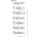
次に、演出制御基板12の動作を説明する。先ず、演出制御用CPU120は、電源が投入されると、図10に示す演出制御メイン処理の実行を開始する。演出制御メイン処理では、まず、RAM領域のクリアや各種初期値の設定、また演出制御の起動間隔(例えば、2ms)を決めるためのタイマの初期設定等を行うための初期化処理を行う(S51)。その後、演出制御用CPU120は、タイマ割込フラグの監視(S52)を行うループ処理に移行する。タイマ割込が発生すると、演出制御用CPU120は、タイマ割込処理によりタイマ割込フラグをセットする。メイン処理で、タイマ割込フラグがセット(オン)されていたら、演出制御用CPU120は、そのフラグをクリアし(S53)、以下の処理を実行する。
Next, the operation of the
演出制御用CPU120は、まず、コマンド解析処理を行う(S54)。コマンド解析処理では、受信コマンドバッファに格納されている主基板11から送信されてきたコマンドが、どのコマンド(図3参照)であるのか解析する。尚、遊技制御用マイクロコンピュータ100から送信された演出制御コマンドは、演出制御INT信号にもとづく割込処理で受信され、RAMに形成されているバッファ領域に保存されている。そして、受信した演出制御コマンドに応じたフラグをセットする処理等を行う。
The
次いで、演出制御用CPU120は、演出制御プロセス処理を行う(S55)。演出制御プロセス処理では、制御状態に応じた各プロセスのうち、現在の制御状態(演出制御プロセスフラグ)に対応した処理を選択して演出表示装置5の表示制御を実行する。
Next, the
次いで、大当り図柄判定用乱数などの演出用乱数を生成するためのカウンタのカウント値を更新する演出用乱数更新処理を実行し(S56)、その後、S52に移行する。 Next, an effect random number update process for updating the counter value for generating effect random numbers such as jackpot symbol determination random numbers is executed (S56), and then the process proceeds to S52.
図11は、演出制御メイン処理の演出制御プロセス処理(S55)を示すフローチャートである。演出制御プロセス処理では、演出制御用CPU120は、先ず、演出表示装置5の第1保留記憶表示エリア5D及び第2保留記憶表示エリア5Uでの保留記憶表示を、保留記憶バッファの記憶内容に応じた表示に更新する保留表示更新処理を実行する(S72)。
FIG. 11 is a flowchart showing the effect control process (S55) of the effect control main process. In the effect control process, the
その後、演出制御用CPU120は、演出制御プロセスフラグの値に応じてS73〜S79のうちのいずれかの処理を行う。各処理においては、以下のような処理を実行する。
Thereafter, the
変動パターン指定コマンド受信待ち処理(S73):遊技制御用マイクロコンピュータ100から変動パターン指定コマンドを受信しているか否か確認する。具体的には、コマンド解析処理で変動パターン指定コマンドを受信しているか否か確認する。変動パターン指定コマンドを受信していれば、演出制御プロセスフラグの値を演出図柄変動開始処理(S74)に対応した値に変更する。
Fluctuation pattern designation command reception waiting process (S73): It is confirmed whether or not a variation pattern designation command is received from the
演出図柄変動開始処理(S74):演出図柄の変動が開始されるように制御する。そして、演出制御プロセスフラグの値を演出図柄変動中処理(S75)に対応した値に更新する。 Effect symbol variation start processing (S74): Control is performed so that the variation of the effect symbol is started. Then, the value of the effect control process flag is updated to a value corresponding to the effect symbol changing process (S75).
演出図柄変動中処理(S75):変動パターンを構成する各変動状態(変動速度)の切替タイミング等を制御するとともに、変動時間の終了を監視する。そして、変動時間が終了したら、演出制御プロセスフラグの値を演出図柄変動停止処理(S76)に対応した値に更新する。 Production symbol variation processing (S75): Controls the switching timing of each variation state (variation speed) constituting the variation pattern and monitors the end of the variation time. When the variation time ends, the value of the effect control process flag is updated to a value corresponding to the effect symbol variation stop process (S76).
演出図柄変動停止処理(S76):全図柄停止を指示する演出制御コマンド(図柄確定コマンド)を受信したことにもとづいて、演出図柄の変動を停止し表示結果(停止図柄)を導出表示する制御を行う。そして、演出制御プロセスフラグの値を大当り表示処理(S77)または変動パターン指定コマンド受信待ち処理(S73)に対応した値に更新する。 Effect symbol variation stop processing (S76): Based on the reception of the effect control command (symbol confirmation command) for instructing all symbols to stop, control is performed to stop the variation of the effect symbol and derive and display the display result (stop symbol). Do. Then, the value of the effect control process flag is updated to a value corresponding to the jackpot display process (S77) or the variation pattern designation command reception waiting process (S73).
大当り表示処理(S77):変動時間の終了後、演出表示装置5に大当りの発生を報知するための画面を表示する制御を行う。そして、演出制御プロセスフラグの値を大当り遊技中処理(S78)に対応した値に更新する。
Jackpot display process (S77): After the end of the variation time, control is performed to display a screen for notifying the
大当り遊技中処理(S78):大当り遊技中の制御を行う。例えば、大入賞口開放中指定コマンドや大入賞口開放後指定コマンドを受信したら、演出表示装置5におけるラウンド数の表示制御等を行う。そして、演出制御プロセスフラグの値を大当り終了演出処理(S79)に対応した値に更新する。
Big hit game processing (S78): Control during the big hit game is performed. For example, when receiving a special command during opening of the special prize opening or a designation command after opening the special prize opening, display control of the number of rounds in the
大当り終了演出処理(S79):演出表示装置5において、大当り遊技状態が終了したことを遊技者に報知する表示制御を行う。そして、演出制御プロセスフラグの値を変動パターン指定コマンド受信待ち処理(S73)に対応した値に更新する。
Big hit end effect process (S79): In the
図12は、図11に示された演出制御プロセス処理におけるS74の演出図柄変動開始処理内で実行される予告演出設定処理を示すフローチャートである。本実施例のパチンコ遊技機1では、演出表示装置5等の演出装置を用いた演出として、大当り信頼度やスーパーリーチとなる信頼度を予告する複数種類の予告演出が実行可能になっている。予告演出設定処理は、パチンコ遊技機1における各種の予告演出の実行有無や実行する場合の演出態様を決定するための処理である。特に、本実施例の予告演出設定処理では、プッシュボタン31Bを振動させる予告演出に係る決定が行われる。
FIG. 12 is a flowchart showing the notice effect setting process executed in the effect symbol variation start process of S74 in the effect control process shown in FIG. In the
予告演出設定処理において、演出制御用CPU120は、まず、予告演出のうち変動開示振動予告の実行有無を決定する(S501)。変動開示振動予告は、変動の開始時に所定時間プッシュボタン31Bを振動させることで大当り信頼度や、スーパーリーチとなる信頼度が高いことを予告する予告演出である。
In the notice effect setting process, the
予告演出や後述する予告示唆において、プッシュボタン31Bを振動させることで、その振動が遊技機用枠3を伝わって遊技者が操作する打球操作ハンドルに伝達される。そのため、遊技者がプッシュボタン31Bに注目していなくてもプッシュボタン31Bが振動していること(予告演出や予告示唆が実行されていること)を把握することができるようになっている。
When the
S501では、今回の変動表示結果に応じて、例えば図13(A)に示す決定割合で変動開始時振動予告の実行有無が決定される。図13(A)に示すように、変動表示結果が「大当り」である場合は20%の割合で変動開始時振動予告を実行すると決定され、変動表示結果が「スーパーリーチはずれ」である場合は5%の割合で変動開始時振動予告を実行すると決定され、変動表示結果が「その他のはずれ」である場合は必ず変動開始時振動予告を実行しないと決定される。このようにすることで、変動開始時振動予告の有無により大当り信頼度やスーパーリーチ信頼度を予告でき、遊技者が変動開始時振動予告の実行有無に注目するようになる。 In S501, whether or not to execute the fluctuation start vibration notice is determined according to the current fluctuation display result, for example, at the determination ratio shown in FIG. As shown in FIG. 13 (A), when the fluctuation display result is “big hit”, it is determined that the vibration notice at the start of fluctuation is executed at a rate of 20%, and when the fluctuation display result is “super reach out” It is determined that the vibration notice at the start of change is executed at a rate of 5%, and when the change display result is “other deviation”, it is determined that the notice of vibration at the start of change is not always executed. By doing so, the jackpot reliability and the super reach reliability can be notified in advance by the presence or absence of the vibration start notice at the start of change, and the player pays attention to whether or not the vibration notice at the start of change is executed.
なお、変動表示結果が「その他のはずれ」である場合は必ず変動開始時振動予告を実行しないと決定されるため、S501の処理の前に「その他のはずれ」であるか否かを判定して、「その他のはずれ」である場合にはS501の処理をスキップするようにしてもよい。また、「その他のはずれ」である場合でも低確率で変動開始時振動予告を実行するようにしてもよい。 In addition, when the fluctuation display result is “other loss”, it is determined that the vibration notice at the start of change is not necessarily executed, so it is determined whether or not “other loss” before the processing of S501. In the case of “other disconnection”, the processing of S501 may be skipped. Further, even in the case of “other loss”, the vibration notice at the start of change may be executed with a low probability.
続いて、演出制御用CPU120は、予告演出のうちボタン予告の実行有無と実行する場合の演出態様を決定する(S502)。ボタン予告は、プッシュボタン31Bへの操作を促す演出を実行し、プッシュボタン31Bが操作されたことによって大当り信頼度やスーパーリーチとなる信頼度を示す予告演出である。本実施例では、ボタン予告が実行されているときに、振動モータ304を駆動させることでプッシュボタン31Bを振動させるようになっている。また、ボタン予告はリーチが成立する前(左右図柄の停止前)のタイミングで実行されるようになっている。
Subsequently, the
S502では、今回の変動表示結果に応じて、例えば図13(B)に示す決定割合でボタン予告の実行有無やボタン予告の演出態様に対応する予告パターンが決定される。本実施例では、ボタン予告における予告パターンとして予告パターンA〜Cのいずれかに決定されるようになっている。予告パターンA〜Cでは、それぞれ演出態様(プッシュボタン31Bが操作されたときに表示される画像等)が異なっている。
In S502, according to the current variation display result, for example, the presence / absence of the button notice and the notice pattern corresponding to the effect state of the button notice are determined at the determination ratio shown in FIG. In the present embodiment, the notice pattern A to C is determined as the notice pattern in the button notice. In the notice patterns A to C, the effect modes (images displayed when the
図13(B)に示すように、変動表示結果が「大当り」である場合は10%の割合で予告パターンAのボタン予告を実行すると決定され、30%の割合で予告パターンBのボタン予告を実行すると決定され、50%の割合で予告パターンCのボタン予告を実行すると決定され、10%の割合でボタン予告を実行しないと決定される。変動表示結果が「スーパーリーチはずれ」である場合は30%の割合で予告パターンAのボタン予告を実行すると決定され、20%の割合で予告パターンBのボタン予告を実行すると決定され、10%の割合で予告パターンCのボタン予告を実行すると決定され、40%の割合でボタン予告を実行しないと決定される。変動表示結果が「その他のはずれ」である場合は7%の割合で予告パターンAのボタン予告を実行すると決定され、3%の割合で予告パターンBのボタン予告を実行すると決定され、予告パターンCのボタン予告を実行することには決定されず、90%の割合でボタン予告を実行しないと決定される。 As shown in FIG. 13B, when the fluctuation display result is “big hit”, it is determined that the button notice of the notice pattern A is executed at a rate of 10%, and the button notice of the notice pattern B is given at a rate of 30%. It is determined to be executed, it is determined to execute the button notification of the notification pattern C at a rate of 50%, and it is determined not to execute the button notification at a rate of 10%. If the fluctuation display result is “Super-reaching”, it is determined that the button notice of the notice pattern A is executed at a rate of 30%, and the button notice of the notice pattern B is decided to be executed at a ratio of 20%. It is determined that the button notice of the notice pattern C is executed at a rate, and it is decided not to execute the button notice at a rate of 40%. When the fluctuation display result is “other off”, it is determined that the button notice of the notice pattern A is executed at a rate of 7%, the button notice of the notice pattern B is decided to be executed at a rate of 3%, and the notice pattern C is decided. It is decided not to execute the button notice at a rate of 90%.
このように、ボタン予告が実行された場合には実行されない場合よりも信頼度が高く、ボタン予告の信頼度は、予告パターンC>予告パターンB>予告パターンAの順に高くなっている。このようにすることで、ボタン予告の有無や予告パターンにより大当り信頼度やスーパーリーチ信頼度を予告でき、遊技者がボタン予告の有無やいずれのボタン予告が実行されるかに注目するようになる。 Thus, when the button notice is executed, the reliability is higher than when the button notice is not executed, and the reliability of the button notice is higher in the order of the notice pattern C> the notice pattern B> the notice pattern A. By doing this, the jackpot reliability and the super reach reliability can be notified by the presence / absence of the button notification and the notification pattern, and the player will be aware of the presence / absence of the button notification and which button notification is executed. .
次に、演出制御用CPU120は、ボタン予告が実行されることを示唆するボタン予告示唆を実行するか否かと実行する場合の示唆態様(振動パターン)を決定する(S503)。ボタン予告示唆は、ボタン予告の実行タイミング以前にプッシュボタン31Bを所定の振動パターンで振動させることで、ボタン予告が実行されることを示唆する演出である。このようなボタン予告示唆が実行された後に、実際にボタン予告が実行される場合と実行されない場合とがあるようになっている。
Next, the
S503では、ボタン予告の実行有無や予告パターンに応じて、例えば図13(C)に示す決定割合でボタン予告示唆の実行有無や振動パターンが決定される。本実施例では、ボタン予告示唆における振動パターンとして振動パターンAと振動パターンBとのいずれかに決定されるようになっている。振動パターンBの方が振動パターンAよりも振動の強度が強くなっている。 In S503, the presence / absence of button notification suggestion and the vibration pattern are determined according to the determination ratio shown in FIG. In this embodiment, the vibration pattern A or the vibration pattern B is determined as the vibration pattern in the button notice suggestion. The vibration pattern B is stronger in vibration than the vibration pattern A.
図13(C)に示すように、ボタン予告が実行されない場合は5%の割合で振動パターンAのボタン予告示唆を実行すると決定され、振動パターンBのボタン予告示唆を実行することには決定されず、95%の割合でボタン予告示唆を実行しないと決定される。予告パターンAのボタン予告が実行さる場合は30%の割合で振動パターンAのボタン予告示唆を実行すると決定され、5%の割合で振動パターンBのボタン予告示唆を実行すると決定され、65%の割合でボタン予告示唆を実行しないと決定される。予告パターンBのボタン予告が実行さる場合は60%の割合で振動パターンAのボタン予告示唆を実行すると決定され、30%の割合で振動パターンBのボタン予告示唆を実行すると決定され、10%の割合でボタン予告示唆を実行しないと決定される。予告パターンCのボタン予告が実行さる場合は30%の割合で振動パターンAのボタン予告示唆を実行すると決定され、70%の割合で振動パターンBのボタン予告示唆を実行すると決定され、ボタン予告示唆を実行しないことには決定されない。 As shown in FIG. 13C, when the button notice is not executed, it is decided to execute the button notice suggestion of the vibration pattern A at a rate of 5%, and it is decided to execute the button notice suggestion of the vibration pattern B. Therefore, it is determined not to execute the button notice suggestion at a rate of 95%. When the button notice of the notice pattern A is executed, it is decided that the button notice suggestion of the vibration pattern A is executed at a ratio of 30%, and it is decided that the button notice suggestion of the vibration pattern B is executed at a ratio of 5%, and 65% It is decided not to execute the button notice suggestion at a rate. When the button notice of the warning pattern B is executed, it is decided to execute the button notice suggestion of the vibration pattern A at a rate of 60%, and it is decided to execute the button notice suggestion of the vibration pattern B at a rate of 30%. It is decided not to execute the button notice suggestion at a rate. When the button notice of the notice pattern C is executed, it is decided to execute the button notice suggestion of the vibration pattern A at a ratio of 30%, and the button notice suggestion of the vibration pattern B is decided to be executed at a ratio of 70%. It is not decided not to execute.
このように、ボタン予告示唆が実行された場合には実行されない場合よりも信頼度の高いボタン予告が実行されやすくなっており、振動パターンAのボタン予告示唆が実行された場合よりも振動パターンBのボタン予告示唆が実行された場合の方が信頼度の高いボタン予告が実行されやすくなっている。また、ボタン予告が実行されない場合は振動パターンBのボタン予告示唆を実行することには決定されないようになっているため、振動パターンBのボタン予告示唆が実行された場合は必ずその後ボタン予告が実行される。このようにすることで、ボタン予告示唆の有無や振動パターンにより、その後ボタン予告が実行されるか否かや予告パターンを示唆することができ、遊技者がボタン予告に先だってプッシュボタン31Bが振動するかに注目するようになる。また、プッシュボタン31Bが振動した後に、プッシュボタン31Bを使用する演出(ボタン予告)が実行されるかに遊技者が注目するようになる。
As described above, when the button notice suggestion is executed, the button notice with higher reliability is more easily executed than when the button notice suggestion is not executed, and the vibration pattern B is more than when the button notice suggestion of the vibration pattern A is executed. When the button notice suggestion is executed, it is easier to execute the button notice with higher reliability. In addition, when the button notice is not executed, it is not decided to execute the button notice suggestion of the vibration pattern B. Therefore, when the button notice suggestion of the vibration pattern B is executed, the button notice is always executed after that. Is done. By doing so, the presence or absence of the button notice suggestion and the vibration pattern can indicate whether or not the button notice will be executed thereafter and the notice pattern, and the
なお、ボタン予告示唆は、プッシュボタン31Bを振動させる演出の中で、その後にプッシュボタン31Bを使用する演出(ボタン予告)が実行される可能性がある演出となっている。これに対して、変動開始時振動予告や後述する発展報知やカットイン予告示唆が実行された後にプッシュボタン31Bを使用する演出が実行されるわけではない。このように、本実施例では、プッシュボタン31Bを振動させる演出が実行された後に、プッシュボタン31Bを使用する演出が実行される場合と実行されない場合とがあるため、演出が多彩になり、プッシュボタン31Bが振動した後に、プッシュボタン31Bを使用する演出が実行されるかに遊技者が注目するようになる。
In addition, the button notice suggestion is an effect in which an effect (button notice) using the
なお、S503では、ボタン予告の実行有無や予告パターンに応じて、ボタン予告示唆の実行有無や振動パターンの決定割合が異なっていたが、最終的な変動表示結果に応じてボタン予告示唆の実行有無や振動パターンの決定割合を異ならせてもよい。例えば、最終的な変動表示結果が「大当り」、「スーパーリーチはずれ」、「その他のはずれ」のいずれであるかに応じて異なる決定割合が設定されたテーブルを用いてボタン予告示唆の実行有無や振動パターンを決定するようにしてもよい。 In S503, the presence / absence of button notification suggestion and the determination ratio of the vibration pattern differ depending on whether or not the button notification is executed and the notification pattern, but whether or not the button notification suggestion is executed according to the final change display result. Alternatively, the determination ratio of the vibration pattern may be varied. For example, using a table with different decision ratios depending on whether the final fluctuation display result is “big hit”, “super-reaching” or “other”, The vibration pattern may be determined.
本実施例では、ボタン予告の実行有無や予告パターンに応じて、ボタン予告示唆の実行有無や振動パターンの決定割合が異なっていたが、ボタン予告の実行有無や予告パターンに応じて、一意に振動パターンに決定されるようにしてもよい。 In this example, the presence / absence of the button notice suggestion and the determination rate of the vibration pattern differ depending on whether or not the button notice is executed and the notice pattern. The pattern may be determined.
また、本実施例では、ボタン予告が実行されない場合でもボタン予告示唆が実行されることがあるようになっているが、ボタン予告が実行されない場合にはボタン予告示唆が実行しないようにしてもよい。 In this embodiment, the button notice suggestion may be executed even when the button notice is not executed. However, when the button notice is not executed, the button notice suggestion may not be executed. .
続いて、演出制御用CPU120は、予告演出のうちカットイン予告の実行有無と実行する場合の演出態様を決定する(S504)。カットイン予告は、リーチが成立した後、リーチ演出中に予告画像やセリフ画像等をカットイン表示させることで大当り信頼度を予告する予告演出である。
Subsequently, the
S504では、変動表示結果に応じて、例えば図13(D)に示す決定割合でカットイン予告の実行有無やカットイン予告の演出態様に対応する予告パターンが決定される。本実施例では、カットイン予告における予告パターンとして予告パターンX〜Xのいずれかに決定されるようになっている。予告パターンX〜Zでは、それぞれ演出態様(カットイン表示される画像等)が異なっている。 In S504, according to the change display result, for example, the notice pattern corresponding to the presence / absence of the cut-in notice and the effect mode of the cut-in notice is decided at the decision ratio shown in FIG. In this embodiment, the notice pattern X to X is determined as the notice pattern in the cut-in notice. The notice patterns X to Z have different effects (cut-in display images and the like).
図13(D)に示すように、変動表示結果が「大当り」である場合は10%の割合で予告パターンXのカットイン予告を実行すると決定され、30%の割合で予告パターンYのカットイン予告を実行すると決定され、50%の割合で予告パターンZのカットイン予告を実行すると決定され、10%の割合でカットイン予告を実行しないと決定される。変動表示結果が「スーパーリーチはずれ」である場合30%の割合で予告パターンXのカットイン予告を実行すると決定され、20%の割合で予告パターンYのカットイン予告を実行すると決定され、10%の割合で予告パターンZのカットイン予告を実行すると決定され、40%の割合でカットイン予告を実行しないと決定される。変動表示結果が「その他のはずれ」である場合は必ずカットイン予告を実行しないと決定される。 As shown in FIG. 13D, when the variation display result is “big hit”, it is determined that the cut-in notice of the notice pattern X is executed at a rate of 10%, and the cut-in notice of the notice pattern Y at a rate of 30%. It is determined that the advance notice is executed, and it is determined that the cut-in advance notice of the notice pattern Z is executed at a rate of 50%, and it is determined that the cut-in advance notice is not executed at a rate of 10%. When the fluctuation display result is “super-reaching out”, it is determined that the cut-in notice of the notice pattern X is executed at a rate of 30%, and it is decided that the cut-in notice of the notice pattern Y is executed at a ratio of 20%. It is determined that the cut-in notice of the notice pattern Z is executed at the rate of 40%, and it is determined that the cut-in notice is not executed at the rate of 40%. When the fluctuation display result is “other loss”, it is determined that the cut-in notice is not always executed.
このように、カット予告が実行された場合には実行されない場合よりも信頼度が高く、カットイン予告の信頼度は、予告パターンZ>予告パターンY>予告パターンXの順に高くなっている。このようにすることで、カットイン予告の有無や予告パターンにより大当り信頼度を予告でき、遊技者がカットイン予告の有無やいずれのカットイン予告が実行されるかに注目するようになる。 Thus, when the cut notice is executed, the reliability is higher than when the cut notice is not executed, and the reliability of the cut-in notice is higher in the order of the notice pattern Z> the notice pattern Y> the notice pattern X. In this way, the reliability of the big hit can be notified based on the presence / absence of the cut-in notice and the notice pattern, and the player pays attention to the presence / absence of the cut-in notice and which cut-in notice is executed.
なお、変動表示結果が「その他のはずれ」である場合は必ずカットイン予告を実行しないと決定されるため、S504の処理の前に「その他のはずれ」であるか否かを判定して、「その他のはずれ」である場合にはS504の処理をスキップするようにしてもよい。また、「その他のはずれ」である場合でも所定のタイミングでカットイン予告を実行可能にしてもよい。 Note that, when the display result of the variation is “other loss”, it is determined that the cut-in notice is not necessarily executed. Therefore, before the processing of S504, it is determined whether or not “other loss”. In the case of “other mistakes”, the process of S504 may be skipped. Further, even in the case of “other loss”, the cut-in notice may be executed at a predetermined timing.
次に、カットイン予告を実行すると決定されたか否かを判定する(S505)。カットイン予告を実行すると決定された場合(S505;Yes)、演出制御用CPU120は、カットイン予告が実行されることを示唆するカットイン予告示唆を実行するか否かを決定する(S506)。カットイン予告示唆は、カットイン予告の実行タイミング以前にプッシュボタン31Bを所定の振動パターンで振動させることで、カットイン予告が実行されることを示唆する演出である。このようなカットイン予告示唆が実行された後には、カットイン予告が必ず実行されるようになっている。そして、カットイン予告示唆の有無に応じていずれの予告パターンのカットイン予告が実行されるかの割合が異なっている。
Next, it is determined whether or not it is determined to execute the cut-in notice (S505). When it is determined to execute the cut-in notice (S505; Yes), the
S506では、カットイン予告の実行有無や予告パターンに応じて、例えば図13(E)に示す決定割合でカットイン予告示唆の実行有無が決定される。図13(E)に示すように、予告パターンXのカットイン予告が実行さる場合は必ずカットイン予告示唆を実行しないと決定され、予告パターンYのカットイン予告が実行さる場合は70%の割合でカットイン予告示唆を実行すると決定され、予告パターンZのカットイン予告が実行さる場合は90%の割合でカットイン予告示唆を実行すると決定される。 In S506, the presence / absence of the cut-in notice suggestion is determined, for example, at the decision ratio shown in FIG. As shown in FIG. 13E, it is determined that the cut-in notice suggestion is not always executed when the cut-in notice of the notice pattern X is executed, and the ratio of 70% when the cut-in notice of the notice pattern Y is executed. Is determined to execute the cut-in notice suggestion, and when the cut-in notice of the notice pattern Z is executed, it is determined to execute the cut-in notice suggestion at a rate of 90%.
このように、カットイン予告示唆が実行された場合には実行されない場合よりも信頼度の高いボタン予告が実行されやすくなっている。このようにすることで、カットイン予告示唆の有無により、その後カットイン予告が実行されることや予告パターンを示唆することができ、遊技者がカットイン予告に先だってプッシュボタン31Bが振動するかに注目するようになる。
Thus, when the cut-in notice suggestion is executed, the button notice with higher reliability is more easily executed than when the cut-in notice suggestion is not executed. By doing so, it is possible to indicate that a cut-in advance notice is to be executed or a notice pattern depending on the presence or absence of the cut-in advance notice, and whether the player vibrates the
なお、S506では、予告パターンに応じて、カットイン予告示唆の実行有無の決定割合が異なっていたが、最終的な変動表示結果に応じてカットイン予告示唆の実行有無の決定割合を異ならせてもよい。例えば、最終的な変動表示結果が「大当り」、「スーパーリーチはずれ」のいずれであるかに応じて異なる決定割合が設定されたテーブルを用いてカットイン予告示唆の実行有無を決定するようにしてもよい。 In S506, the determination rate of whether or not cut-in notification suggestion is performed differs depending on the notification pattern. However, the determination ratio of whether or not cut-in notification suggestion is performed differs depending on the final change display result. Also good. For example, whether or not to execute the cut-in notice suggestion is determined using a table in which different determination ratios are set depending on whether the final fluctuation display result is “big hit” or “out of super reach”. Also good.
また、本実施例では、カットイン予告が実行されない場合にはカットイン予告示唆が実行されないようになっているが、カットイン予告が実行されない場合にもカットイン予告示唆が実行されることがあるようにしてもよい。 In this embodiment, the cut-in notice suggestion is not executed when the cut-in notice is not executed, but the cut-in notice suggestion may be executed even when the cut-in notice is not executed. You may do it.
カットイン予告を実行しないと決定された場合や(S505;No)、S506の処理を実行した後には、S501〜S504及びS506における決定結果をRAMの所定領域に保存して(S507)、予告演出設定処理を終了する。その後、図11に示す演出図柄変動開始処理や演出図柄変動中処理において、ここで保存された予告演出に係る決定結果が参照されることで、決定結果に対応した予告演出が実行される。 When it is determined not to execute the cut-in notice (S505; No), after the process of S506 is executed, the determination results in S501 to S504 and S506 are stored in a predetermined area of the RAM (S507), and the notice effect is produced. The setting process ends. Thereafter, in the effect symbol variation start process and the effect symbol variation in-process shown in FIG. 11, the notice effect corresponding to the decision result is executed by referring to the determination result related to the notice effect saved here.
なお、図13(A)〜(E)に示した決定割合は、一例であり、各種予告演出や予告示唆によって大当り信頼度、スーパーリーチとなる信頼度、予告演出が実行され得ること等を好適に予告・示唆できればこの割合に限定されない。また、予告演出や予告示唆として他の演出が実行されるようにしてもよい。 The determination ratios shown in FIGS. 13A to 13E are only examples, and it is preferable that the jackpot reliability, the reliability that becomes super reach, the notification effect can be executed by various notification effects and notification suggestions, etc. This ratio is not limited as long as it can be notified and suggested. Further, other effects may be executed as a notice effect or a notice suggestion.
また、変動開始時振動予告やカットイン予告示唆は1パターンのみであったが、振動態様や振動時間が異なる複数パターンの変動開始時振動予告やカットイン予告示唆を実行するようにしてもよい。そして、いずれのパターンであるかによって、大当り信頼度、スーパーリーチとなる信頼度、予告演出の実行割合等が異なるようにしてもよい。 Further, although the vibration start notice and the cut-in notice suggestion are only one pattern, the change start vibration notice and the cut-in notice suggestion of a plurality of patterns having different vibration modes and vibration times may be executed. And depending on which pattern it is, you may make it the big hit reliability, the reliability which becomes the super reach, the execution ratio of the notice production etc. differ.
続いて、本実施例のパチンコ遊技機1において可変表示が実行されているときに、プッシュボタン31Bを振動させるタイミングについて説明する。図14は、演出表示装置5等における演出内容と振動動作のタイミングを示すタイミングチャートである。
Next, the timing at which the
上述したように、本実施例では、予告演出や予告示唆の実行時にプッシュボタン31Bを振動させるようになっている。図14に示すように、変動開始時振動予告を実行することが決定されているときには、変動開始にプッシュボタン31Bを振動させる。また、ボタン予告示唆を実行することが決定されているときには、ボタン予告の実行タイミング以前にプッシュボタン31Bを振動させる。ボタン予告を実行することが決定されているときには、ボタン予告の実行タイミングにおいてプッシュボタン31Bを振動させる。カットイン予告示唆を実行することが決定されているときには、カットイン予告の実行タイミング以前にプッシュボタン31Bを振動させる。
As described above, in this embodiment, the
また、本実施例では、リーチが成立してノーマルリーチのリーチ演出中にスーパーリーチに発展するタイミングにおいて、スーパーリーチに発展したことを報知するため、プッシュボタン31Bを振動させるようになっている。なお、本実施例では、スーパーリーチに発展する場合には必ずこのような発展報知が実行されるようになっているが、変動表示結果が「大当り」となるか否かに応じて、発展報知の実行割合が異なるようにしてもよい。例えば、発展報知が実行された場合の方が実行されない場合よりも大当り信頼度が高くなるようにしてもよい。また、スーパーリーチの種類に応じて発展報知を実行するか否かを異ならせてもよい。例えば、大当り信頼度の高いスーパーリーチである場合に発展報知を実行し(または高い割合で実行し)、大当り信頼度の低いスーパーリーチである場合に発展報知を実行しない(または低い割合で実行する)ようにしてもよい。このようにすることで、スーパーリーチに発展する場合の発展報知の有無によって大当り信頼度やリーチの種類を示唆することができる。
Further, in this embodiment, the
また、本実施例では、スーパーリーチのリーチ演出が実行されたときには、可変表示が終了する直前のタイミングにおいて、変動表示結果が「大当り」となるかを煽る当否煽りが実行されるようになっている。当否煽りでは、演出表示装置5にプッシュボタン31Bへの操作を促す画像を表示する等、プッシュボタン31Bへの操作を促す演出を実行し、表示結果導出以前にプッシュボタン31Bが操作された場合には、変動表示結果(大当りまたははずれ)を報知する画像を表示する。そして、この当否煽りの実行中においてもプッシュボタン31Bを振動させるようになっている。
Further, in this embodiment, when the reach effect of the super reach is executed, at the timing immediately before the end of the variable display, a win / no-go whether or not the variable display result is “big hit” is executed. Yes. In the case of success or failure, an effect that prompts the user to operate the
図14に示すように、本実施例では、変動開始時振動予告、ボタン予告示唆、ボタン予告、カットイン予告示唆、発展報知、当否煽りといった複数のタイミングでプッシュボタン31Bが振動するようになっている。そして、本実施例では、プッシュボタン31Bの振動パターンが複数設けられており、いずれの演出(タイミング)において振動させるかや操作の有無に応じて振動パターンが異ならせている。
As shown in FIG. 14, in this embodiment, the
図15は、プッシュボタン31Bの振動パターンの一覧を示す図である。図15に示すように、プッシュボタン31Bの振動パターンとして、振動パターンA〜Dという4パターンが設けられており、振動の強度は振動パターンD>振動パターンC>振動パターンB振動パターンAの順に強くなっている。例えば、振動モータ304を駆動する際の印加電圧を異ならせることで、プッシュボタン31Bの振動強度を異ならせる。なお、各振動パターンにおける振動の強度の異ならせ方はこれに限定されず、振動駆動モータ304の駆動のオンオフを所定周期で切り替えるようにして、オフの期間を長くすることで振動強度を弱くするようにしてもよい。また、動作させるモータの数を異ならせることで振動の強度を異ならせてもよい。
FIG. 15 is a diagram showing a list of vibration patterns of the
図15に示すように、ボタン予告示唆(振動パターンAに決定時)やボタン予告における遊技者の操作前では、振動パターンAでプッシュボタン31Bを振動させ、ボタン予告示唆(振動パターンBに決定時)やボタン予告における遊技者の操作前、カットイン予告示唆、発展報知では、振動パターンBでプッシュボタン31Bを振動させ、変動開始時振動予告、ボタン予告における遊技者の操作時、当否煽りにおける遊技者の操作前では、振動パターンCでプッシュボタン31Bを振動させ、当否煽りにおける遊技者の操作時(大当り報知時)では、振動パターンDでプッシュボタン31Bを振動させるようになっている。
As shown in FIG. 15, the
このように、演出内容によって振動パターンを異ならせることでプッシュボタン31Bを振動させる演出が多彩になり、演出の興趣が向上する。
In this way, by changing the vibration pattern depending on the contents of the effects, the effects of vibrating the
なお、常に振動強度が最強の振動パターンDでプッシュボタン31Bを振動させると、主基板11、演出制御基板12、電源基板といった各種基板や他の部材に振動が伝達して故障や不具合の原因になるおそれがある。本実施例のように、適宜振動強度を低下させた振動パターンで演出を実行することで、演出が多彩になるとともに、そのような故障や不具合を低減できる。
If the
また、ボタン予告においては、遊技者の操作前には振動パターンAまたはBで振動させ、遊技者の操作時にはより振動強度の強い振動パターンCで振動させる。当否煽り時においては、遊技者の操作前には振動パターンCで振動させ、遊技者の操作時(大当り報知時)にはより振動強度の強い振動パターンDで振動させる。このように、ボタン予告や当否煽りにおいては、遊技者の操作時には操作前よりも振動強度の強い振動パターンでプッシュボタン31Bを振動させるので、遊技者のプッシュボタン31B押下による振動の減退を低減でき、遊技者に振動を好適に伝達することができる。
Further, in the button notice, the player vibrates with the vibration pattern A or B before the player's operation, and vibrates with the vibration pattern C having a stronger vibration intensity when the player operates. At the time of winning or failing, it is vibrated with the vibration pattern C before the player's operation, and is vibrated with the vibration pattern D having a stronger vibration intensity when the player is operating (at the time of big hit notification). As described above, in the button notice or the success or failure of the button, the
図16は、プッシュボタン31Bへの操作の検出有無に応じた振動パターンの変化の具体例を示す図である。図16(A)は、ボタン予告示唆がある場合のボタン予告実行時の振動パターンの変化を示している。図16(A)に示すように、ボタン予告の実行タイミングの所定時間前に、振動パターンAまたはBでプッシュボタン31Bを振動させるボタン予告示唆が実行される。ここでの振動パターンは、図12のS502において決定された振動パターンとなる。その後、演出表示装置5においてプッシュボタン31Bへの操作を促すボタン予告が実行され、プッシュセンサ35Bによりプッシュボタン31Bへの押下操作が検出されると、振動パターンを振動パターンAまたはBよりも強い振動パターンCに切り替える。また、図16(A)に示すように、ボタン予告が開始されてからプッシュボタン31Bへの押下操作が検出されるまでは、ボタン予告示唆における振動パターンを引き継ぐようになっている。このようにすることで、ボタン予告示唆とボタン予告とに連続性を持たせることができる。なお、ボタン予告が開始されてからプッシュボタン31Bへの押下操作が検出されるまでは、固定の振動パターン(例えば振動パターンB)で振動させるようにしてもよい。
FIG. 16 is a diagram illustrating a specific example of a vibration pattern change according to whether or not an operation on the
図16(B)は、ボタン予告示唆がない場合のボタン予告実行時の振動パターンの変化を示している。図16(B)に示すように、ボタン予告の実行タイミングにおいて、振動パターンBでプッシュボタン31Bを振動させる。このように、ボタン予告示唆がない場合、ボタン予告開始時は振動パターンBでプッシュボタン31Bを振動させるようになっている。その後、プッシュセンサ35Bによりプッシュボタン31Bへの押下操作が検出されると、振動パターンを振動パターンBよりも強い振動パターンCに切り替える。
FIG. 16B shows a change in the vibration pattern at the time of executing the button notice when there is no button notice suggestion. As shown in FIG. 16 (B), the
以上のように、ボタン予告では、プッシュボタン31Bへの押下操作が検出前は振動パターンAまたはBでプッシュボタン31Bを振動させ、押下操作が検出されると振動パターンAまたはBよりも強い振動パターンCに切り替える。このようにすることで、遊技者のプッシュボタン31B押下による振動の減退を低減でき、遊技者に振動を好適に伝達することができる。
As described above, in the button notice, the
図16(C)は、変動表示結果が「大当り」の場合の当否煽りの振動パターンの変化を示している。図16(C)に示すように、当否煽りの実行タイミングにおいて、振動パターンCでプッシュボタン31Bを振動させる。その後、プッシュセンサ35Bによりプッシュボタン31Bへの押下操作が検出されると、変動表示結果が「大当り」であることが報知され、振動パターンを振動パターンCよりも強い振動パターンDに切り替える。図15に示すように、振動パターンDは、振動パターンA〜Dの中で最も強い振動をする振動パターンであり、「大当り」の報知時のみ使用されるようになっている。このように、「大当り」となることの報知に最も強くプッシュボタン31Bを振動させることで、振動パターンにより大当りを報知できるとともに、遊技者の喜びに合った報知が実行でき、振動による好適な大当り報知を実行することができる。
FIG. 16C shows a change in the vibration pattern of the success / failure when the fluctuation display result is “big hit”. As shown in FIG. 16C, the
このように、大当り時の当否煽りでは、プッシュボタン31Bへの押下操作が検出前は振動パターンCでプッシュボタン31Bを振動させ、押下操作が検出されると振動パターンCよりも強い振動パターンDに切り替える。このようにすることで、遊技者のプッシュボタン31B押下による振動の減退を低減でき、遊技者に振動を好適に伝達することができる。
As described above, when hitting or not at the time of a big hit, the
図16(D)は、変動表示結果が「はずれ」の場合の当否煽りの振動パターンの変化を示している。図16(D)に示すように、当否煽りの実行タイミングにおいて、振動パターンCでプッシュボタン31Bを振動させる。その後、プッシュセンサ35Bによりプッシュボタン31Bへの押下操作が検出されると、変動表示結果が「はずれ」であることが報知され、プッシュボタン31Bの振動は停止する。このように、変動表示結果が「はずれ」となる場合には、余計な煽りを防止するため、プッシュボタン31Bの振動を停止するようになっている。なお、プッシュボタン31Bの振動を操作検出前より弱くしたり、減退させるようにしてもよい。
FIG. 16D shows a change in the vibration pattern of the success / failure when the fluctuation display result is “out of”. As shown in FIG. 16D, the
なお、図16(A)〜(C)では、振動パターンを切り替える場合、即時振動パターン切り替えるようになっていたが、振動パターンを切り替えるときに無振動期間を挟むようにしてもよい。図16(E)は、振動パターンを切り替えるときに無振動期間を挟むようにした変形例において、ボタン予告示唆がない場合のボタン予告実行時の振動パターンの変化を示している。図16(E)に示すように、ボタン予告の実行タイミングにおいて、振動パターンBでプッシュボタン31Bを振動させる。その後、プッシュセンサ35Bによりプッシュボタン31Bへの押下操作が検出されると、一旦プッシュボタン31Bの振動を停止させ、その後振動パターンを振動パターンBよりも強い振動パターンCに切り替える。このように、振動パターンを切り替えるときに、一旦無振動期間を挟むことで振動パターンが切り替わったことを遊技者が把握しやすくなる。
In FIGS. 16A to 16C, when switching the vibration pattern, the immediate vibration pattern is switched. However, when switching the vibration pattern, a non-vibration period may be interposed. FIG. 16E shows a change in the vibration pattern at the time of button notice execution when there is no button notice suggestion in a modification in which a vibration-free period is sandwiched when changing the vibration pattern. As shown in FIG. 16E, the
図17は、図11に示された演出制御プロセス処理におけるS75の演出図柄変動中処理内で実行される振動モータ駆動処理を示すフローチャートである。ボタン駆動モータ駆動処理は、演出図柄変動中処理における振動モータ304を駆動してプッシュボタン31Bを振動させる部分である。
FIG. 17 is a flowchart showing the vibration motor drive process executed in the effect symbol changing process of S75 in the effect control process shown in FIG. The button drive motor drive process is a part that drives the
ボタン駆動モータ駆動処理において、演出制御用CPU120は、まず、変動開始時振動予告を実行することに決定され、かつその実行タイミングであるか否かを判定する(S511)。変動開始時振動予告を実行することに決定され、かつその実行タイミングであると判定された場合(S511;Yes)、振動パターンCで振動モータ304を振動させる駆動制御を実行する(S512)。なお、各種演出の実行タイミングであるか否かは変動プロセスタイマ、変動時間タイマの値等から判定すればよい。
In the button drive motor driving process, the
次に、演出制御用CPU120は、ボタン予告示唆を実行することに決定され、かつその実行タイミングであるか否かを判定する(S513)。ボタン予告示唆を実行することに決定され、かつその実行タイミングであると判定された場合(S513;Yes)、図12のS502における決定結果に応じて振動パターンAまたはBで振動モータ304を振動させる駆動制御を実行する(S514)。
Next, the
次に、演出制御用CPU120は、ボタン予告を実行することに決定され、かつその実行タイミングであるか否かを判定する(S515)。ボタン予告を実行することに決定され、かつその実行タイミングであると判定された場合(S515;Yes)、図12のS502における決定結果に応じて振動パターンAまたはBで振動モータ304を振動させる駆動制御を実行する(S516)。図12のS502においてボタン予告示唆を実行すると決定された場合には決定された振動パターンで振動させ、ボタン予告示唆を実行しないと決定された場合には振動パターンBで振動させる駆動制御を実行する。
Next, the
次に、演出制御用CPU120は、ボタン予告の実行中であり、かつプッシュセンサ35Bによりプッシュボタン31Bへの押下操作が検出されたか否かを判定する(S517)。ボタン予告の実行中であり、かつ押下操作が検出されたと判定された場合(S517;Yes)、振動パターンCで振動モータ304を振動させる駆動制御を実行する(S518)。
Next, the
次に、演出制御用CPU120は、スーパーリーチの変動パターンでありそのリーチの発展タイミングであるか否かを判定する(S519)。リーチの発展タイミングであると判定された場合(S519;Yes)、振動パターンBで振動モータ304を振動させる駆動制御を実行する(S520)。
Next, the
次に、演出制御用CPU120は、カットイン予告示唆を実行することに決定され、かつその実行タイミングであるか否かを判定する(S521)。カットイン予告示唆を実行することに決定され、かつその実行タイミングであると判定された場合(S521;Yes)、振動パターンBで振動モータ304を振動させる駆動制御を実行する(S522)。
Next, the
次に、演出制御用CPU120は、スーパーリーチの変動パターンであり当否煽りの実行タイミングであるか否かを判定する(S523)。当否煽りの実行タイミングであると判定された場合(S523;Yes)、振動パターンCで振動モータ304を振動させる駆動制御を実行する(S524)。
Next, the
次に、演出制御用CPU120は、当否煽りの実行中であり、かつプッシュセンサ35Bによりプッシュボタン31Bへの押下操作が検出されたか否かを判定する(S525)。当否煽りの実行中であり、かつ押下操作が検出されたと判定された場合(S525;Yes)、今回の変動表示結果が「大当り」であるか否かを判定する(S526)。今回の変動表示結果が「大当り」であると判定された場合(S526;Yes)、振動パターンDで振動モータ304を振動させる駆動制御を実行する(S527)。今回の変動表示結果が「大当り」でないと判定された場合(S526;No)、振動モータ304を停止させる制御を実行する(S529)。
Next, the
最後に、演出制御用CPU120は、振動の停止タイミングであるか否かを判定する(S528)。振動の停止タイミングであるかは、例えば振動の開始時に振動時間に対応したタイマをスタートさせ当該タイマがタイムアウトしたか否かで判定すればよい。振動の停止タイミングであると判定された場合(S528;Yes)、振動モータ304を停止させる制御を実行する(S529)。その後、振動モータ駆動処理を終了する。
Finally, the
振動駆動モータ304による振動が主基板11、演出制御基板12、電源基板といった各種基板や他の部材に伝わって故障や不具合が生じてしまうことを防止するために、振動駆動モータ304を備える機構と、他の基板との間にゴムやゲル等の緩衝部材を設けるようにしてもよい。
A mechanism including the
検出手段(プッシュセンサ35B)により操作が検出されていないときに操作手段(プッシュボタン31B)が振動した場合、その後に操作演出(ボタン予告)が実行される場合と操作演出が実行されない場合(振動後にプッシュボタン31Bを操作させる演出を実行しない場合、他の演出を実行する場合)とがあり、操作手段は振動に伴って発光可能に構成された発光手段(例えばLED)を有し、発光手段が発光した場合、その後に操作演出が実行される場合と操作演出が実行されない場合とがあるようにしてもよい。
When the operation means (push
スーパーリーチのリーチ演出中において遊技者に対してプッシュボタン31Bの操作を促す操作促進画像及び操作促進メッセージを演出表示装置5に表示する演出(ボタン演出)を実行するようにしてもよい。そして、変動表示結果が大当りであれば、プッシュボタン31Bの操作に基づいて可動役物400を動作させて大当りの報知を行うようにしてもよい。また、このときに、プッシュボタン31Bを突出状態に変化させるようにしてもよい。このようなボタン演出は、カットイン予告と重複しないタイミングで実行されればよい。また、ボタン演出とリーチ演出中に実行される他の演出(カットイン予告や当否煽り)とが択一的に実行されるようにしてもよい。当否煽りとして、以下に示すボタン演出を実行するようにしてもよい。
An effect (button effect) for displaying an operation promotion image and an operation promotion message for prompting the player to operate the
以下、スーパーリーチのリーチ演出中において遊技者に対してプッシュボタン31Bの操作を促す操作促進画像及び操作促進メッセージを演出表示装置5に表示する演出を実行する場合の処理や演出動作について説明する。
Hereinafter, a process and an effect operation in the case where an effect of displaying an operation promotion image and an operation promotion message for prompting the player to operate the
図18は、図11に示された演出制御プロセス処理における演出図柄変動開始処理(S74)を示すフローチャートである。演出図柄変動開始処理において、演出制御用CPU120は、まず、S271において第1変動開始コマンド受信フラグがセットされているか否かを判定する(S271)。第1変動開始コマンド受信フラグがセットされている場合は(S271;Y)、バッファ番号「1−1」〜「1−4」に対応した領域に対応付けて格納されている各種コマンドデータと各種フラグを、バッファ番号1個分ずつ上位にシフトする(S272)。尚、バッファ番号「1−1」の内容については、シフトする先が存在しないためにシフトすることはできないので消去される。
FIG. 18 is a flowchart showing the effect symbol variation start process (S74) in the effect control process shown in FIG. In the effect symbol variation start process, the
また、S271において第1変動開始コマンド受信フラグがセットされていない場合は(S271;N)、第2変動開始コマンド受信フラグがセットされているか否かを判定する(S273)。第2変動開始コマンド受信フラグがセットされていない場合は(S273;N)、演出図柄変動開始処理を終了し、第2変動開始コマンド受信フラグがセットされている場合は(S273;Y)、バッファ番号「2−1」〜「2−4」に対応した領域に対応付けて格納されている各種コマンドデータと各種フラグを、バッファ番号1個分ずつ上位にシフトする(S274)。尚、バッファ番号「2−1」の内容については、シフトする先が存在しないためにシフトすることはできないので消去される。 If the first variation start command reception flag is not set in S271 (S271; N), it is determined whether or not the second variation start command reception flag is set (S273). When the second variation start command reception flag is not set (S273; N), the effect symbol variation start process is terminated, and when the second variation start command reception flag is set (S273; Y), the buffer The various command data and various flags stored in association with the areas corresponding to the numbers “2-1” to “2-4” are shifted upward by one buffer number (S274). Note that the contents of the buffer number “2-1” are erased because they cannot be shifted because there is no destination to shift.
S272またはS274の実行後、演出制御用CPU120は、変動パターン指定コマンド格納領域から変動パターン指定コマンドを読み出す(S275)。
After execution of S272 or S274, the
次いで、表示結果指定コマンド格納領域に格納されているデータ(即ち、受信した表示結果指定コマンド)に応じて演出図柄の表示結果(停止図柄)を決定する(S276)。この場合、演出制御用CPU120は、表示結果指定コマンドで指定される表示結果に応じた演出図柄の停止図柄を決定し、決定した演出図柄の停止図柄を示すデータを演出図柄表示結果格納領域に格納する。
Next, the display result of the effect symbol (stop symbol) is determined according to the data stored in the display result specification command storage area (that is, the received display result specification command) (S276). In this case, the
尚、この実施例では、受信した変動表示結果指定コマンドが確変大当りAに該当する第2変動表示結果指定コマンドである場合において、演出制御用CPU120は、例えば、停止図柄として3図柄が「7」で揃った演出図柄の組合せ(大当り図柄)を決定する。また、受信した変動表示結果指定コマンドが確変大当りBに該当する第3変動表示結果指定コマンドである場合においては、停止図柄として、「7」以外の奇数図柄の複数の組合せ(例えば「111」、「333」、「555」、「999」などの演出図柄の組合せ)の中から決定する。また、受信した変動表示結果指定コマンドが非確変大当りに該当する第4変動表示結果指定コマンドである場合において、演出制御用CPU120は、例えば、停止図柄として3図柄が偶数図柄で揃った演出図柄の組合せ(大当り図柄)を決定する。また、受信した変動表示結果指定コマンドが、はずれに該当する第1変動表示結果指定コマンドである場合には、停止図柄として3図柄が不揃いとなる演出図柄の組合せ(はずれ図柄)を決定する。
In this embodiment, when the received variation display result designation command is the second variation display result designation command corresponding to the probability variation big hit A, the
これら停止図柄の決定においては、演出制御用CPU120は、例えば、停止図柄を決定するための乱数を抽出し、演出図柄の組合せを示すデータと数値とが対応付けられている停止図柄判定テーブルを用いて、演出図柄の停止図柄を決定すれば良い。即ち、抽出した乱数に一致する数値に対応する演出図柄の組合せを示すデータを選択することによって停止図柄を決定すれば良い。
In determining these stop symbols, the
次いで、演出制御用CPU120は、S275において読み出した変動パターン指定コマンドから当該変動表示の変動パターンを特定し、該変動パターンがスーパーリーチの変動パターンであるか否かを判定する(S277)。スーパーリーチの変動パターンである場合(S277;Y)は、リーチ演出中において遊技者に対してプッシュボタン31Bの操作を促す操作促進画像及び操作促進メッセージを演出表示装置5に表示する際にプッシュボタン31Bを突出状態に変化させるか否かを、図示しないプッシュボタン突出決定テーブルと変動表示結果及びプッシュボタン突出決定用乱数値に基づいて決定して記憶する(S278)。
Next, the
尚、S278においては、図19に示すように、変動表示結果が「はずれ」である場合は、10%の割合でプッシュボタン31Bの突出(突出状態への変化)の実行を決定し、90%の割合でプッシュボタン31Bの突出の非実行を決定する。また、変動表示結果が「大当り」である場合は、90%の割合でプッシュボタン31Bの突出(突出状態への変化)の実行を決定し、10%の割合でプッシュボタン31Bの突出の非実行を決定する。このように、変動表示結果が「大当り」である場合は、変動表示結果が「はずれ」である場合よりも高い割合でプッシュボタン31Bの突出(突出状態への変化)の実行を決定するので、プッシュボタン31Bの操作を促す操作促進画像及び操作促進メッセージが演出表示装置5に表示される際にプッシュボタン31Bが突出状態に変化するか否かに対して遊技者を注目させることができるので、遊技興趣を向上できる。
In S278, as shown in FIG. 19, when the fluctuation display result is “out of”, execution of the
そして、スーパーリーチの変動パターンでない場合(S277;N)やS278の実行後は、プッシュボタン31Bの突出の有無と変動パターン指定コマンドに応じた演出制御パターン(プロセステーブル)を選択する。そして、選択したプロセステーブルのプロセスデータ1における変動プロセスタイマをスタートさせる(S282)。
If the variation pattern is not a super reach variation pattern (S277; N) or after the execution of S278, the presence / absence of the
尚、プロセステーブルには、演出表示装置5の表示を制御するための表示制御実行データ、各LEDの点灯を制御するためのLED制御実行データ、スピーカ8L,8Rから出力する音の制御するための音制御実行データや、可動役物400の動作を制御するための可動役物制御実行データ、プッシュボタン31Bの操作を制御するための操作部制御実行データ等が、各プロセスデータn(1〜N番まで)に対応付けて時系列に順番配列されている。
In the process table, display control execution data for controlling display of the
次いで、演出制御用CPU120は、変動プロセスデータ1の内容(表示制御実行データ1、LED制御実行データ1、音制御実行データ1、可動役物制御実行データ1、操作部制御実行データ1)に従って演出装置(演出用部品としての演出表示装置5、演出用部品としての各種LED及び演出用部品としてのスピーカ8L,8R、可動役物400、操作部(プッシュボタン31B等))の制御を実行する(S283)。例えば、演出表示装置5において変動パターンに応じた画像を表示させるために、表示制御部123に指令を出力する。また、各種LEDを点灯/消灯制御を行わせるために、LED制御基板14に対して制御信号(LED制御実行データ)を出力する。また、スピーカ8L,8Rからの音声出力を行わせるために、音声制御基板13に対して制御信号(音番号データ)を出力する。
Next, the
尚、この実施例では、演出制御用CPU120は、変動パターン指定コマンドに1対1に対応する変動パターンによる演出図柄の変動表示が行われるように制御するが、演出制御用CPU120は、変動パターン指定コマンドに対応する複数種類の変動パターンから、使用する変動パターンを選択するようにしてもよい。
In this embodiment, the
そして、変動時間タイマに、変動パターン指定コマンドで特定される変動時間に相当する値を設定する(S284)。また、変動制御タイマに所定時間を設定する(S285)。尚、所定時間は例えば30msであり、演出制御用CPU120は、所定時間が経過する毎に左中右の演出図柄の表示状態を示す画像データをVRAMに書き込み、表示制御部123がVRAMに書き込まれた画像データに応じた信号を演出表示装置5に出力し、演出表示装置5が信号に応じた画像を表示することによって演出図柄の変動が実現される。次いで、演出制御プロセスフラグの値を演出図柄変動中処理(S75)に対応した値にする(S286)。
Then, a value corresponding to the variation time specified by the variation pattern designation command is set in the variation time timer (S284). Further, a predetermined time is set in the fluctuation control timer (S285). The predetermined time is, for example, 30 ms, and the
図20は、演出制御プロセス処理における演出図柄変動中処理(S75)を示すフローチャートである。演出図柄変動中処理において、演出制御用CPU120は、変動プロセスタイマ、変動時間タイマ、変動制御タイマのそれぞれの値を−1する(S301,S302,S303)。
FIG. 20 is a flowchart showing the effect symbol variation in-process (S75) in the effect control process. In the effect symbol changing process, the
S304において演出制御用CPU120は、変動プロセスタイマがタイマアウトしたか否か確認する。変動プロセスタイマがタイマアウトしていたら(S304;Y)、変動プロセスデータの切り替えを行う(S305)。即ち、プロセステーブルにおける次に設定されているプロセスタイマ設定値を変動プロセスタイマに設定することによって変動プロセスタイマをあらためてスタートさせる(S306)。また、その次に設定されている表示制御実行データ、LED制御実行データ、音制御実行データ、可動役物制御実行データ、操作部制御実行データ等にもとづいて演出装置(演出用部品)に対する制御状態を変更する(S307)。一方、変動プロセスタイマがタイマアウトしていない場合(S304;N)は、変動プロセスタイマに対応する変動プロセスデータの内容(表示制御実行データ、LED制御実行データ、音制御実行データ、可動役物制御実行データ、操作部制御実行データ等)に従って演出装置(演出用部品)の制御を実行する(S308)。
In S304, the
次に、演出制御用CPU120は、当該変動表示の変動パターンがスーパーリーチの変動パターンであるか否かを判定する(S309)。当該変動表示の変動パターンがスーパーリーチの変動パターンでない場合(S309;N)はS324に進み、当該変動表示の変動パターンがスーパーリーチの変動パターンである場合(S309;Y)は、プッシュボタン31Bの操作が受け付けられたことを示すプッシュボタン操作受付フラグがセットされているか否かを判定する(S310)。プッシュボタン操作受付フラグがセットされている場合(S310;Y)はS323に進み、プッシュボタン操作受付フラグがセットされていない場合は、プッシュボタン31Bの突出状態への変化が決定されているか否かを判定する(S311)。
Next, the
プッシュボタン31Bの突出状態への変化が決定されていない場合(S311;N)はS314に進み、プッシュボタン31Bの突出状態への変化が決定されている場合(S311;Y)は、変動プロセスデータを参照してボタン駆動モータ303の駆動期間中であるか否かを判定する(S312)。ボタン駆動モータ303の駆動期間中でない場合(S312;N)はS314に進み、ボタン駆動モータ303の駆動期間中である場合(S312;Y)は、ボタン駆動モータ303を駆動させてS314に進む(S313)。
When the change to the protruding state of the
S314において演出制御用CPU120は、変動プロセスデータを参照してプッシュボタン31Bの操作受付開始タイミングであるか否かを判定する。プッシュボタン31Bの操作受付開始タイミングでない場合(S314;N)はS316に進み、プッシュボタン31Bの操作受付開始タイミングである場合(S314;Y)は、プッシュボタン31Bの突出の有無(プッシュボタン31Bを突出状態に変化させるか否かの決定)に応じた操作促進画像の表示を演出表示装置5にて開始する(S315a)。また、遊技者に対してプッシュボタン31Bの操作を促す操作促進メッセージの表示を演出表示装置5にて開始する(S315b)。そして、S316に進む。
In S314, the
S316において演出制御用CPU120は、変動プロセスデータを参照してプッシュボタン31Bの操作受付期間中であるか否かを判定する。プッシュボタン31Bの操作受付期間中でない場合(S316;N)はS324に進み、プッシュボタン31Bの操作受付期間中である場合(S316;Y)は、更に、プッシュボタン31Bの操作受付有りか否か(プッシュボタン31Bが操作されたか否か)を判定する(S317)。尚、本実施例においてプッシュボタン31Bが操作されたことを判定するタイミングは、プッシュセンサ35が遊技者によるプッシュボタン31Bの操作終了を検出したタイミングであるが、本発明はこれに限定されるものではなく、プッシュボタン31Bが操作されたことを判定するタイミングは、プッシュセンサ35が遊技者によるプッシュボタン31Bの操作開始を検出したタイミングであってもよい。
In S316, the
また、本実施例では、後述するように、遊技者によるプッシュボタン31Bの操作に基づいて可動役物400が退避位置から演出位置に移動(落下)することにより変動表示結果が大当りとなることを報知する形態を例示しているが、本発明はこれに限定されるものではなく、遊技者によるプッシュボタン31Bの操作態様は、短期間での1回操作(単発押し)の他、継続操作(長押し)や複数回操作(連打)等のうち、いずれか1の操作態様のみを設けてもよいし、複数の操作態様を設けてもよい。
Further, in this embodiment, as will be described later, when the
プッシュボタン31Bの操作受付有りの場合(S317;Y)はS321aに進み、プッシュボタン31Bの操作受付無しの場合(S317;N)は、更にプッシュボタン31Bの操作受付終了タイミングであるか否かを判定する(S319)。プッシュボタン31Bの操作受付終了タイミングである場合(S319;Y)はS321aに進み、プッシュボタン31Bの操作受付終了タイミングでない場合(S319;N)はS322に進む。
If the
S321aにおいて演出制御用CPU120は、プッシュボタン31Bの操作受付期間中にプッシュボタン31Bが操作されたこと、または、プッシュボタン31Bが操作されることなくプッシュボタン31Bの操作受付期間が終了したことに基づいてプッシュボタン操作受付フラグをセットする。また、演出表示装置5における操作促進画像の表示を維持しつつ操作促進メッセージの表示を終了してS322に進む(S321b)。
In S321a, the
S322において演出制御用CPU120は、プッシュボタン操作受付フラグがセットされているか否かを判定する。プッシュボタン操作受付フラグがセットされている場合(S322;Y)はS323に進み、プッシュボタン操作受付フラグがセットされていない場合はS324に進む。尚、S323において演出制御用CPU120は、プッシュボタン31Bの操作受付期間中にプッシュボタン31Bが操作されたこと、または、プッシュボタン31Bが操作されることなくプッシュボタン31Bの操作受付期間が終了したことに基づいて操作後演出を実行するための操作後演出実行処理を実行してS324に進む。
In S322, the
次に、変動制御タイマがタイマアウトしているか否かを確認する(S324)。変動制御タイマがタイマアウトしている場合には(S324;Y)、演出制御用CPU120は、左中右の演出図柄の次表示画面(前回の演出図柄の表示切り替え時点から30ms経過後に表示されるべき画面)の画像データを作成し、VRAMの所定領域に書き込む(S325)。そのようにして、演出表示装置5において、演出図柄の変動制御が実現される。表示制御部123は、設定されている背景画像等の所定領域の画像データと、プロセステーブルに設定されている表示制御実行データにもとづく画像データとを重畳したデータに基づく信号を演出表示装置5に出力する。そのようにして、演出表示装置5において、演出図柄の変動における背景画像、キャラクタ画像及び演出図柄が表示される。また、変動制御タイマに所定値を再セットする(S326)。
Next, it is confirmed whether or not the fluctuation control timer has expired (S324). When the variation control timer has timed out (S324; Y), the
また、変動制御タイマがタイマアウトしていない場合(S324;N)、S326の実行後、演出制御用CPU120は、変動時間タイマがタイマアウトしているか否か確認する(S327)。変動時間タイマがタイマアウトしていれば、演出制御プロセスフラグの値を演出図柄変動停止処理(S76)に応じた値に更新する(S329)。変動時間タイマがタイマアウトしていなくても、図柄確定指定コマンドを受信したことを示す確定コマンド受信フラグがセットされていたら(S328;Y)、演出制御プロセスフラグの値を演出図柄変動停止処理(S76)に応じた値に更新する(S329)。変動時間タイマがタイマアウトしていなくても図柄確定指定コマンドを受信したら変動を停止させる制御に移行するので、例えば、基板間でのノイズ等に起因して長い変動時間を示す変動パターン指定コマンドを受信したような場合でも、正規の変動時間経過時(特別図柄の変動終了時)に、演出図柄の変動を終了させることができる。
If the variation control timer has not timed out (S324; N), after executing S326, the
尚、演出図柄の変動制御に用いられているプロセステーブルには、演出図柄の変動表示中のプロセスデータが設定されている。つまり、プロセステーブルにおけるプロセスデータ1〜nのプロセスタイマ設定値の和は演出図柄の変動時間に相当する。よって、S304の処理において最後のプロセスデータnのプロセスタイマがタイマアウトしたときには、切り替えるべきプロセスデータ(表示制御実行データやLED制御実行データ等)はなく、プロセステーブルにもとづく演出図柄の演出制御は終了する。
In the process table used for the variation control of the effect symbol, process data during the effect symbol variation display is set. That is, the sum of the process timer setting values of the
図21は、演出図柄変動中処理における操作後演出実行処理(S323)を示すフローチャートである。操作後演出実行処理において、演出制御用CPU120は、先ず、操作後演出プロセスタイマが動作中であるか否かを判定する(S401)。操作後演出プロセスタイマが動作中である場合(S401;Y)はS408に進み、操作後演出プロセスタイマが動作中でない場合(S401;N)は、変動表示結果が大当りであるか否かを判定する(S402)。変動表示結果が大当りである場合(S402;Y)は大当り用の操作後演出プロセステーブルを選択し(S403)、変動表示結果がはずれである場合(S402;N)ははずれ用の操作後演出プロセステーブルを選択する(S404)。
FIG. 21 is a flowchart showing post-operation effect execution processing (S323) in effect symbol variation processing. In the post-operation effect execution process, the
そして、S403またはS404の実行後は、選択した操作後演出プロセステーブルのプロセスデータ1における操作後演出プロセスタイマをスタートさせる(S405)。
And after execution of S403 or S404, the post-operation presentation process timer in the
尚、操作後演出プロセステーブルには、演出表示装置5の表示を制御するための表示制御実行データ、各LEDの点灯を制御するためのLED制御実行データ、スピーカ8L,8Rから出力する音の制御するための音制御実行データや、可動役物400の動作を制御するための可動役物制御実行データ等が、各プロセスデータn(1〜N番まで)に対応付けて時系列に順番配列されている。
The post-operation effect process table includes display control execution data for controlling the display of the
次いで、演出制御用CPU120は、操作後演出プロセスデータ1の内容(表示制御実行データ1、LED制御実行データ1、音制御実行データ1、可動役物制御実行データ1、)に従って演出装置(演出用部品としての演出表示装置5、演出用部品としての各種LED及び演出用部品としてのスピーカ8L,8R、可動役物400等))の制御を実行する(S406)。例えば、演出表示装置5において変動表示結果に応じた画像を表示させるために、表示制御部123に指令を出力する。また、各種LEDを点灯/消灯制御を行わせるために、LED制御基板14に対して制御信号(LED制御実行データ)を出力する。また、スピーカ8L,8Rからの音声出力を行わせるために、音声制御基板13に対して制御信号(音番号データ)を出力する。また、可動役物400を動作させるために、可動役物第1駆動モータ301や可動役物第2駆動モータ302を駆動させる。また、演出表示装置5に表示されている操作促進画像を操作後画像として更新を開始して操作後演出実行処理を終了する(S407)。
Next, the
また、S408において演出制御用CPU120は、操作後演出プロセスタイマの値を−1する。そして、操作後演出プロセスタイマがタイマアウトしたか否かを判定する(S409)。操作後演出プロセスタイマがタイマアウトした場合(S409;Y)は、操作後演出プロセスデータの切り替えを行う(S410)。即ち、操作後演出プロセステーブルにおける次に設定されているプロセスタイマ設定値を操作後演出プロセスタイマに設定することによって操作後演出プロセスタイマをあらためてスタートさせる(S411)。また、その次に設定されている表示制御実行データ、LED制御実行データ、音制御実行データ、可動役物制御実行データ等にもとづいて演出装置(演出用部品)に対する制御状態を変更する(S412)。一方、操作後演出プロセスタイマがタイマアウトしていない場合(S409;N)は、操作後演出プロセスタイマに対応する操作後演出プロセスデータの内容(表示制御実行データ、LED制御実行データ、音制御実行データ、可動役物制御実行データ等)に従って演出装置(演出用部品)の制御を実行する(S413)。
In S408, the
そして、S412またはS413の実行後は、演出表示装置5に表示されている操作後画像を更新し(S414)、変動表示結果が大当りであるか否かを判定する(S415)。変動表示結果がはずれである場合(S415;N)は操作後演出実行処理を終了し、変動表示結果が大当りである場合(S415;Y)は、可動役物第1駆動モータ301の正転駆動期間中であるか否か、つまり、可動役物400の退避位置から演出位置に向けての移動期間中であるか否かを判定する(S416)。可動役物第1駆動モータ301の正転駆動期間中である場合(S416;Y)は可動役物第1駆動モータ301を正転駆動させることによって可動役物400を演出位置に向けて移動させ、S418に進む(S417)。また、可動役物第1駆動モータ301の正転駆動期間中でない場合(S416;N)は、S417を経由することなくS418に進む。
Then, after the execution of S412 or S413, the post-operation image displayed on the
S418において演出制御用CPU120は、可動役物第1駆動モータ301の逆転駆動期間中であるか否か、つまり、可動役物400の演出位置から退避位置に向けての移動期間中であるか否かを判定する。可動役物第1駆動モータ301の逆転駆動期間中である場合(S418;Y)は、可動役物第1駆動モータ301を逆転駆動させることによって可動役物400を退避位置に向けて移動させ、S420に進む(S419)。また、可動役物第1駆動モータ301の逆転駆動期間中でない場合(S418;N)は、S419を経由することなくS420に進む。
In S418, the
S420において演出制御用CPU120は、可動役物第2駆動モータ302の正転駆動期間中であるか否か、つまり、可動役物400が演出位置に位置している状態において、可動役物400を第1可動部401と第2可動部402とが近接する近接状態から第1可動部401と第2可動部402とが離間する離間状態に変化させる期間中であるか否かを判定する。可動役物第2駆動モータ302の正転駆動期間中である場合(S420;Y)は、可動役物第2駆動モータ302を正転駆動させることによって可動役物400を離間状態に変化させるとともに(S421)、演出表示装置5に可動役物400が退避位置に移動したことに対応するエフェクト画像を表示してS423に進む(S422)。また、可動役物第2駆動モータ302の正転駆動期間中でない場合(S420;N)は、S421及びS422を経由せず、つまり、演出表示装置5でのプッシュボタン31Bの画像の表示中であれば、該プッシュボタン31Bの画像の表示を継続してS423に進む。
In S420, the
S423において演出制御用CPU120は、可動役物第2駆動モータ302の逆転駆動期間中であるか否か、つまり、可動役物400が演出位置に位置している状態において第1可動部401及び第2可動部402の離間位置から近接位置に向けての移動期間中であるか否かを判定する。可動役物第2駆動モータ302の逆転駆動期間中である場合(S423;Y)は、可動役物第2駆動モータ302を逆転駆動させることによって第1可動部401及び第2可動部402を近接位置に向けて移動させて操作後演出実行処理を終了する(S424)。また、可動役物第2駆動モータ302の逆転駆動期間中でない場合(S423;N)は、S424を経由せずに操作後演出実行処理を終了する。
In S423, the
以上のように演出制御用CPU120によって演出図柄変動開始処理、演出図柄変動中処理、操作後演出実行処理が実行されることによって、スーパーリーチの変動表示においてプッシュボタン31Bを突出させず(演出図柄変動開始処理のS278においてプッシュボタン31Bの非突出状態から突出状態への変化の非実行を決定した場合)変動表示結果が大当りとなる場合は、図22(A)に示すように、変動開始から期間L1が経過したタイミング(リーチ演出実行中のタイミング)から演出表示装置5に操作促進画像としての非突出状態のプッシュボタン31Bの画像と操作促進メッセージの表示が開始される。そして、プッシュボタン31Bの操作受付期間中にプッシュボタン31Bが操作されるかプッシュボタン31Bが操作されることなく該操作受付期間が経過した場合は、プッシュボタン31Bの操作を受け付けたタイミング、または、プッシュボタン31Bの操作受付期間が終了したタイミングにおいて操作促進メッセージの表示が終了する。
As described above, the
また、プッシュボタン31Bの操作を受け付けたタイミング、または、プッシュボタン31Bの操作受付期間が終了したタイミングから期間L2に亘って、操作促進画像(非突出状態のプッシュボタン31Bの画像)である操作後画像が演出表示装置5から消去される。更に、プッシュボタン31Bの操作を受け付けたタイミング、または、プッシュボタン31Bの操作受付期間が終了したタイミングから期間L2よりも長い期間である期間L3に亘って、可動役物400を図1に示す退避位置から演出表示装置5と重畳する演出位置に向けての移動(落下)が実行される。
In addition, after the operation that is the operation promotion image (image of the
可動役物400の演出位置への移動完了後は、第1可動部401及び第2可動部402を移動させることによって演出位置において可動役物400を近接状態から離間状態に変化させた後、可動役物400を離間状態から近接状態に変化させる。そして、再び可動役物400を演出位置から退避位置に移動させ、変動表示が終了する。
After the movement of the
スーパーリーチの変動表示においてプッシュボタン31Bを突出させて(演出図柄変動開始処理のS278においてプッシュボタン31Bの非突出状態から突出状態への変化の実行を決定した場合)変動表示結果が大当りとなる場合は、図22(B)に示すように、変動開始から期間L1が経過したタイミング(リーチ演出実行中のタイミング)から演出表示装置5に操作促進画像としての突出状態のプッシュボタン31Bの画像と操作促進メッセージの表示が開始される。尚、プッシュボタン31Bは、リーチ演出中における操作促進画像や操作促進メッセージの表示開始前タイミングの直前に非突出状態から突出状態に変化する。そして、プッシュボタン31Bの操作受付期間中にプッシュボタン31Bが操作されるかプッシュボタン31Bが操作されることなく該操作受付期間が経過した場合は、プッシュボタン31Bの操作を受け付けたタイミング、または、プッシュボタン31Bの操作受付期間が終了したタイミングにおいて操作促進メッセージの表示が終了する。
When the
また、プッシュボタン31Bの操作を受け付けたタイミング、または、プッシュボタン31Bの操作受付期間が終了したタイミングから期間L3に亘って、可動役物400を図1に示す退避位置から演出表示装置5と重畳する演出位置に向けての移動(落下)が実行される。
Further, the
更に、可動役物400の退避位置から演出位置への移動(落下)期間中は、操作後演出として、操作促進画像(突出状態のプッシュボタン31Bの画像)である操作後画像を、非突出状態のプッシュボタン31Bの画像に更新する。このように、可動役物400の退避位置から演出位置への移動に併せて操作後演出を実行することで、遊技者に対してあたかも落下する可動役物400が突出状態のプッシュボタン31Bの画像を操作して非突出状態に変化させるように見せることができる。
Further, during the movement (falling) period from the retracted position to the effect position of the
尚、本実施例では、操作後画像である突出状態のプッシュボタン31Bの画像を非突出状態のプッシュボタン31Bの画像に更新することによって、落下する可動役物400が突出状態のプッシュボタン31Bの画像を操作して非突出状態に変化させるように見せる形態を例示しているが、本発明はこれに限定されるものではなく、操作後画像である突出状態のプッシュボタン31Bの画像は、可動役物400が突出状態のプッシュボタン31Bの画像を操作するように遊技者に対して見せかけることができるのであれば非突出状態のプッシュボタン31Bの画像とは異なる画像に更新するようにしてもよい。
In the present embodiment, the image of the
操作後演出として操作後画像である非突出状態のプッシュボタン31Bの画像の更新が終了した後は、該非突出状態のプッシュボタン31Bの画像が期間L2に亘って演出表示装置5から消去される。尚、本実施例では、図22(B)に示すように、突出状態から非突出状態に変化した後のプッシュボタン31Bの画像の消去が終了するタイミングが可動役物400の退避位置から演出位置への移動完了タイミングと同一タイミングとなっているが、本発明はこれに限定されるものではなく、突出状態から非突出状態に変化した後のプッシュボタン31Bの画像の消去が終了するタイミングと可動役物400の退避位置から演出位置への移動完了タイミングとは異なるタイミングであってもよい。
After the update of the
可動役物400の演出位置への移動完了後は、第1可動部401及び第2可動部402を移動させることによって演出位置において可動役物400を近接状態から離間状態に変化させる。尚、可動役物400の離間状態への変化が完了したタイミングでは、演出表示装置5に、可動役物400が演出位置において離間状態に変化したことを示すエフェクト画像を表示する。そして、可動役物400を離間状態から近接状態に変化させた後、再び可動役物400を演出位置から退避位置に移動させ、変動表示が終了する。
After the movement of the
スーパーリーチの変動表示においてプッシュボタン31Bを突出させず(演出図柄変動開始処理のS278においてプッシュボタン31Bの非突出状態から突出状態への変化の非実行を決定した場合)変動表示結果がはずれとなる場合は、図23(A)に示すように、変動開始から期間L1が経過したタイミング(リーチ演出実行中のタイミング)から演出表示装置5に操作促進画像としての非突出状態のプッシュボタン31Bの画像と操作促進メッセージの表示が開始される。そして、プッシュボタン31Bの操作受付期間中にプッシュボタン31Bが操作されるかプッシュボタン31Bが操作されることなく該操作受付期間が経過した場合は、プッシュボタン31Bの操作を受け付けたタイミング、または、プッシュボタン31Bの操作受付期間が終了したタイミングにおいて操作促進メッセージの表示が終了する。
In the super reach variation display, the
また、プッシュボタン31Bの操作を受け付けたタイミング、または、プッシュボタン31Bの操作受付期間が終了したタイミングから期間L2に亘って、操作促進画像(非突出状態のプッシュボタン31Bの画像)である操作後画像が演出表示装置5から消去される。そして、可動役物400が退避位置から演出位置に向けて移動(落下することなく)変動表示が終了する。
In addition, after the operation that is the operation promotion image (image of the
スーパーリーチの変動表示においてプッシュボタン31Bを突出させて(演出図柄変動開始処理のS278においてプッシュボタン31Bの非突出状態から突出状態への変化の実行を決定した場合)変動表示結果がはずれとなる場合は、図23(B)に示すように、変動開始から期間L1が経過したタイミング(リーチ演出実行中のタイミング)から演出表示装置5に操作促進画像としての突出状態のプッシュボタン31Bの画像と操作促進メッセージの表示が開始される。尚、プッシュボタン31Bは、リーチ演出中における操作促進画像や操作促進メッセージの表示開始前タイミングの直前に非突出状態から突出状態に変化する。そして、プッシュボタン31Bの操作受付期間中にプッシュボタン31Bが操作されるかプッシュボタン31Bが操作されることなく該操作受付期間が経過した場合は、プッシュボタン31Bの操作を受け付けたタイミング、または、プッシュボタン31Bの操作受付期間が終了したタイミングにおいて操作促進メッセージの表示が終了する。
When the
そして、プッシュボタン31Bの操作を受け付けたタイミング、または、プッシュボタン31Bの操作受付期間が終了したタイミングから期間L2に亘って、操作促進画像(突出状態のプッシュボタン31Bの画像)である操作後画像が演出表示装置5から消去される。そして、可動役物400が退避位置から演出位置に向けて移動(落下)することなく変動表示が終了する。
Then, the post-operation image which is an operation promotion image (image of the
次に、スーパーリーチの変動表示においてプッシュボタン31Bを突出させることが決定されている場合での演出表示装置5の表示態様及び可動役物400の動作態様について図24及び図25に基づいて説明する。
Next, the display mode of the
先ず、図24(A)〜図24(D)に示すように、可動役物400が退避位置に配置されている状態において演出図柄がリーチの組み合わせとなると、演出表示装置5においてリーチ演出(スーパーリーチ演出)が開始される。該スーパーリーチ演出中は、所定時間が経過すると、ボタン駆動モータ303の駆動によって非突出状態のプッシュボタン31Bが突出状態に変化する。そして、図24(E)に示すように、演出表示装置5に操作促進画像として突出状態のプッシュボタン31Bの画像と「押せ!!」等の操作促進メッセージが表示され、プッシュボタン31Bの操作の受け付けが開始される。
First, as shown in FIGS. 24 (A) to 24 (D), when the effect symbol becomes a combination of reach in the state where the
プッシュボタン31Bの操作受付期間中に遊技者がプッシュボタン31Bを操作する、または、遊技者がプッシュボタン31Bを操作することなくプッシュボタン31Bの操作受付期間が終了すると、図25(F)〜図25(H)に示すように、演出表示装置5から操作促進メッセージが消去され、可動役物400が退避位置から演出位置に向けて移動(落下)を開始する。更に、該可動役物400の移動(落下)に連動して、操作後画像としての突出状態のプッシュボタン31Bの画像が非突出状態のプッシュボタン31Bの画像に漸次更新されている。
When the player operates the
そして、図25(I)及び図25(J)に示すように、可動役物400の演出位置への移動(落下)と非突出状態のプッシュボタン31Bの画像への更新が完了すると、演出表示装置5での操作後画像として非突出状態のプッシュボタン31Bの画像の表示が終了され、可動役物400が近接状態から離間状態に変化する。また、演出表示装置5にエフェクト画像を表示する。
Then, as shown in FIGS. 25 (I) and 25 (J), when the movement of the
以上、本実施例のパチンコ遊技機1にあっては、図25に示すように、遊技者が突出状態のプッシュボタン31Bを操作したことに基づいて、操作後演出として可動役物400を落下させるとともに演出表示装置5に表示されている突出状態のプッシュボタン31Bの画像を非突出状態のプッシュボタン31Bの画像に更新する(変化させる)ことによって、可動役物400があたかも突出状態のプッシュボタン31B画像を操作したように見せかけることができるので、これら可動役物400の動作とプッシュボタン31Bの画像の表示態様の変化との対応によって遊技興趣を向上できる。尚、本実施例では、操作促進画像である突出状態のプッシュボタン31Bの画像が変化する例として、非突出状態のプッシュボタン31Bの画像に更新される形態を開示しているが、本発明はこれに限定されるものではなく、操作促進画像である突出状態のプッシュボタン31Bの画像の変化には、該プッシュボタン31Bの画像が非突出状態のプッシュボタン31Bの画像に変化した後、更に演出表示装置5から消去されるまでを含んでもよい。
As described above, in the
尚、本実施例では、可動役物400を落下させることによって可動役物400があたかも突出状態のプッシュボタン31Bの画像を操作したように見せかける形態を例示したが、本発明はこれに限定されるものではなく、突出状態のプッシュボタン31Bの画像を操作したように見せかけることが可能であれば、可動役物400の動作態様は落下以外であってもよい。
In the present embodiment, the form in which the
また、操作後演出では、可動役物400の落下に応じて突出状態のプッシュボタン31Bの画像が非突出状態のプッシュボタン31Bの画像に更新されるので、可動役物400の落下に対応してプッシュボタン31Bの画像の表示態様が変化したことを遊技者が認識し易くなるため、遊技興趣を向上できる。
Further, in the post-operation effect, the image of the
また、操作後演出では、可動役物400の落下に応じて突出状態のプッシュボタン31Bの画像が非突出状態のプッシュボタン31Bの画像に更新された後に、該非突出状態のプッシュボタン31Bの画像を演出表示装置5から消去することで、操作後演出における可動役物400の落下による演出効果を向上できる。
Further, in the post-operation effect, after the image of the
尚、本実施例の操作後演出では、可動役物400の落下に応じて突出状態のプッシュボタン31Bの画像を非突出状態のプッシュボタン31Bの画像に更新した後、該非突出状態のプッシュボタン31Bの画像を演出表示装置5から消去する形態を例示したが、本発明はこれに限定されるものではなく、操作後演出では、可動役物400の落下に応じて突出状態のプッシュボタン31Bの画像を非突出状態のプッシュボタン31Bの画像に更新することなく消去するようにしてもよいし、可動役物400の落下に応じて突出状態のプッシュボタン31Bの画像を非突出状態のプッシュボタン31Bの画像に更新した後に演出表示装置5から消去しないようにしてもよい。つまり、本発明において、『操作体対応画像(突出状態のプッシュボタン31Bの画像)の表示態様を可動体(可動役物400)の動作に対応して変化させることには、突出状態のプッシュボタン31Bの画像を非突出状態のプッシュボタン31Bの画像に更新することと、演出表示装置5からプッシュボタン31Bの画像を消去することの両方が含まれている。
In the post-operation effect of the present embodiment, the image of the
また、本実施例では、操作後演出が開始されてから演出表示装置5から操作後画像であるプッシュボタン31Bの画像を消去するので、可動役物400の落下に対応してプッシュボタン31Bの画像が消去されたことを遊技者が認識し易くなるので、遊技興趣を向上できる。
Further, in the present embodiment, the image of the
また、スーパーリーチの変動表示においてに変動表示結果がはずれとなる、つまり、プッシュボタン31Bの操作に基づいて操作後演出として可動役物400の移動(落下)が実行されない場合は、突出状態のプッシュボタン31Bが操作された場合と非突出状態のプッシュボタン31Bが操作された場合とのいずれにおいても、プッシュボタン31Bの画像が期間L2に亘って演出表示装置5から消去される、つまり、同一タイミングでプッシュボタン31Bの画像が演出表示装置5から消去されるので、突出状態のプッシュボタン31Bが操作された場合と非突出状態のプッシュボタン31Bが操作された場合とで可動役物400の移動(落下)が実行されないときのプッシュボタン31Bの画像の表示期間を共通とすることができ、遊技興趣の低下を防ぐことができる。
Further, in the case of super reach variation display, the variation display result is out of order, that is, when the movement (drop) of the
尚、本実施例では、プッシュボタン31Bの操作に基づいて操作後演出として可動役物400の移動(落下)が実行されない場合は、突出状態のプッシュボタン31Bが操作された場合と非突出状態のプッシュボタン31Bが操作された場合とで共通のタイミングで演出表示装置5からプッシュボタン31Bの画像を消去する形態を例示したが、本発明はこれに限定されるものではなく、プッシュボタン31Bの操作に基づいて操作後演出として可動役物400の移動(落下)が実行されない場合は、突出状態のプッシュボタン31Bが操作された場合と非突出状態のプッシュボタン31Bが操作された場合とで異なるタイミングで演出表示装置5からプッシュボタン31Bの画像を消去してもよい。
In this embodiment, when the
また、スーパーリーチの変動表示においてプッシュボタン31Bを突出させて(演出図柄変動開始処理のS278においてプッシュボタン31Bの非突出状態から突出状態への変化の実行を決定した場合)変動表示結果が大当りとなる場合は、図22(B)に示すように、プッシュボタン31Bの操作に基づいて、該プッシュボタン31Bが操作されてから期間L3が経過したことに基づいてプッシュボタン31Bの画像を消去し、スーパーリーチの変動表示においてプッシュボタン31Bを突出させて(演出図柄変動開始処理のS278においてプッシュボタン31Bの非突出状態から突出状態への変化の実行を決定した場合)変動表示結果がはずれとなる場合は、図23(B)に示すように、プッシュボタン31Bの操作に基づいて、該プッシュボタン31Bが操作されてから期間L2(期間L3>期間L2)が経過したことに基づいてプッシュボタン31Bの画像を消去する、つまり、プッシュボタン31Bが突出状態に変化しても、プッシュボタン31Bが操作されたことに基づいて可動役物400の移動(落下)が実行される場合と実行されない場合とでプッシュボタン31Bの画像の表示を終了する態様が異なるので、遊技興趣を向上できる。
Further, when the
また、スーパーリーチの変動表示においてプッシュボタン31Bを突出させず(演出図柄変動開始処理のS278においてプッシュボタン31Bの非突出状態から突出状態への変化の非実行を決定した場合)変動表示結果が大当りとなる場合は、図22(A)に示すように、プッシュボタン31Bが操作されてから期間L2に亘って操作後画像である非突出状態のプッシュボタン31Bの画像を演出表示装置5から消去し、スーパーリーチの変動表示においてプッシュボタン31Bを突出させて(演出図柄変動開始処理のS278においてプッシュボタン31Bの非突出状態から突出状態への変化の実行を決定した場合)変動表示結果が大当りとなる場合は、図22(B)に示すように、プッシュボタン31Bが操作されてから期間L3(期間L3>期間L2)に亘って、突出状態のプッシュボタン31Bの画像を非突出状態のプッシュボタン31Bの画像への更新と、操作後画像である該非突出状態のプッシュボタン31Bの画像の演出表示装置5からの消去を実行する、つまり、演出表示装置5に表示されるプッシュボタン31Bの表示態様に応じてプッシュボタン31Bが操作されてからプッシュボタン31Bの画像の表示が終了されるまでの期間が異なるとにより、遊技興趣を向上できる。特に、期間L3は、期間L2よりも長い期間であり、該期間L3中に突出状態のプッシュボタン31Bの画像を非突出状態のプッシュボタン31Bの画像に更新することができるので、該プッシュボタン31Bの画像の更新に遊技者を注目させることができ、遊技興趣を向上できる。更に、期間L3中に突出状態のプッシュボタン31Bの画像を非突出状態のプッシュボタン31Bの画像に更新することで、可動役物400の移動(落下)に対応してプッシュボタン31Bの画像が更新されたことを遊技者が認識し易くなるので、遊技興趣を向上できる。
In addition, the
また、スーパーリーチの変動表示において操作促進画像として表示されるプッシュボタン31Bの画像は、非突出状態のプッシュボタン31Bを示す画像と、突出状態のプッシュボタン31Bを示す画像と、であるので、操作促進画像としてプッシュボタン31Bの態様(突出状態または非突出状態)に適したプッシュボタン31Bの画像を演出表示装置5に表示することができる。
Further, the images of the
また、プッシュボタン31Bの突出の実行を決定した場合とプッシュボタン31Bの突出の非実行を決定した場合とでは、図22(A)、図22(B)、図23(A)、図23(B)に示すように、同一タイミング(変動開始から期間L1が経過したタイミング)から、操作促進画像として突出状態のプッシュボタン31Bの画像または非突出状態のプッシュボタン31Bの画像の表示を開始するので、突出状態のプッシュボタン31Bの画像や非突出状態のプッシュボタン31Bの画像の表示が開始されるタイミングを遊技者が認識し易くなるので、遊技興趣を向上できる。尚、本実施例では、本発明における第1操作促進表示を非突出状態のプッシュボタン31Bの画像、第2操作促進表示を突出状態のプッシュボタン31Bの画像とし、これら非突出状態のプッシュボタン31Bの画像と突出状態のプッシュボタン31Bの画像とを、同一タイミング(変動開始から期間L1が経過したタイミング)から操作促進画像として演出表示装置5に表示する形態を例示しているが、本発明はこれに限定されるものではなく、これら非突出状態のプッシュボタン31Bの画像と突出状態のプッシュボタン31Bの画像とは、異なるタイミングから操作促進画像として演出表示装置5に表示してもよい。つまり、第1操作促進表示と第2操作促進表示とは、それぞれプッシュボタン31Bが非突出状態のときの異なるタイミングで表示されるものでもよく、また、それぞれプッシュボタン31Bが突出状態のときの異なるタイミングで表示されるものでもよい。
In addition, when the execution of the
また、操作後演出において可動役物400が退避位置から演出位置に移動(落下)した際には、演出表示装置5に表示されているプッシュボタン31Bの画像を更新しつつ維持する一方で、可動役物400が演出位置に配置されているときに、第1可動部401と第2可動部402とを可動役物400の左右幅方向略中央部に近接配置されている状態から互いが離間するように移動させることによって、可動役物400を近接状態から離間状態に変化させた場合は、演出表示装置5にプッシュボタン31Bの画像とは異なるエフェクト画像を表示することにより、好適に操作後演出を実行することができる。
When the
また、操作後演出は、遊技者によるプッシュボタン31Bの操作に基づいて実行されるので、遊技興趣を向上できる。
Further, since the post-operation effect is executed based on the operation of the
また、演出表示装置5に操作促進画像として表示される突出状態のプッシュボタン31Bの画像は、可動役物400が退避位置から演出位置に向けて移動(落下)したことに連動して、操作後画像として非突出状態のプッシュボタン31Bの画像に更新されるので、遊技興趣を向上できる。
In addition, the image of the
また、操作後演出において可動役物400が退避位置から演出位置に向けて移動(落下)する場合には、操作後画像として、突出状態のプッシュボタン31Bの画像が非突出状態のプッシュボタン31Bの画像に更新されつつ継続して表示されるので、遊技興趣を向上できる。
Further, when the
尚、本実施例では、本発明における所定画像であるプッシュボタン31Bの画像を、可動役物400が演出位置において近接状態から離間状態に変化開始する前のタイミングで演出表示装置5から消去する形態を例示しているが、本発明はこれに限定されるものではなく、プッシュボタン31Bの画像は、可動役物400が演出位置において近接状態から離間状態に変化開始タイミングで演出表示装置5から消去してもよい。このようにすることで、可動役物400の近接状態から離間状態への変化に対応して演出表示装置5にプッシュボタン31Bの画像に替えてエフェクト画像が表示されるので、操作後演出の演出効果を高めることができる。
In this embodiment, the image of the
また、図22(B)に示すように、リーチ演出中にプッシュボタン31Bが遊技者によって操作された場合には、プッシュボタン31Bが操作されたタイミングにおいて本発明における補助画像としての操作促進メッセージを演出表示装置5から消去し、操作後画像であるプッシュボタン31Bの画像は、可動役物400の落下が完了したタイミング(プッシュボタン31Bが操作されてから期間L3が経過したタイミング)にて演出表示装置5から消去されるので、遊技興趣を向上しつつ、プッシュボタン31Bの操作がパチンコ遊技機1(演出制御用CPU120)に認識されたことを遊技者が把握し易くできる。
In addition, as shown in FIG. 22B, when the
以上、本発明の実施例を図面により説明してきたが、具体的な構成はこれら実施例に限られるものではなく、本発明の要旨を逸脱しない範囲における変更や追加があっても本発明に含まれる。 Although the embodiments of the present invention have been described with reference to the drawings, the specific configuration is not limited to these embodiments, and modifications and additions within the scope of the present invention are included in the present invention. It is.
例えば、前記実施例では、操作後演出として、突出状態のプッシュボタン31Bが遊技者によって操作されたことに基づいて可動役物400を退避位置から演出位置に移動(落下)させるとともに、演出表示装置5に表示されている突出状態のプッシュボタン31Bの画像を非突出状態のプッシュボタン31Bの画像に更新することで、あたかも可動役物400がプッシュボタン31Bの画像を操作しているように見せる形態を例示しているが、本発明はこれに限定されるものではなく、変形例1として図26(A)〜図26(C)に示すように、操作後演出では、可動役物400の退避位置から演出位置への移動(落下)に替えて、演出表示装置5に突出状態のプッシュボタン31Bの画像に所定のキャラクタ画像が作用する作用演出を表示するようにしてもよい。このようにすることで、作用演出に対応して突出状態のプッシュボタン31Bの画像が非突出状態のプッシュボタン31Bの画像に更新されるので、該作用演出に遊技者を注目させ、遊技興趣を向上できる。
For example, in the embodiment, as the post-operation effect, the
尚、本変形例1では、作用演出に対応させてプッシュボタン31Bの画像の態様を変化させる形態を例示したが、本発明はこれに限定されるものではなく、プッシュボタン31Bの画像の態様に対応させる演出は、作用演出以外の演出であってもよい。
In addition, in this
また、前記実施例では、図22及び図23に示すように、演出表示装置5に突出状態のプッシュボタン31Bの画像の表示を開始するタイミングと非突出状態のプッシュボタン31Bの画像の表示を開始するタイミングとが同一である(変動開始から期間L1が経過したタイミング)形態を例示しているが、本発明はこれに限定されるものではなく、変形例2として、突出状態のプッシュボタン31Bの画像の表示を開始するタイミングと非突出状態のプッシュボタン31Bの画像の表示を開始するタイミングとが異なるようにしてもよい。
Moreover, in the said Example, as shown in FIG.22 and FIG.23, the timing which starts the display of the image of
尚、このように突出状態のプッシュボタン31Bの画像の表示を開始するタイミングと非突出状態のプッシュボタン31Bの画像の表示を開始するタイミングとが異なる場合は、突出状態のプッシュボタン31Bの画像が表示されているときにプッシュボタン31Bが操作されたことに基づいて該突出状態のプッシュボタン31Bの画像を消去する態様と、非突出状態のプッシュボタン31Bの画像が表示されているときにプッシュボタン31Bが操作されたことに基づいて該非突出状態のプッシュボタン31Bの画像を消去する態様と、が異なるようにし、遊技興趣を向上できるようにしてもよい。
When the timing for starting the display of the image of the
また、前記実施例のリーチ演出中に操作促進画像として突出状態のプッシュボタン31Bの画像が表示される場合は、操作促進画像として非突出状態のプッシュボタン31Bの画像が表示される場合よりも変動表示結果が大当たりとなる割合が高い形態を例示しているが、本発明はこれに限定されるものではなく、演出表示装置5に非突出状態のプッシュボタン31Bの画像を表示した後、該非突出状態のプッシュボタン31Bの画像が突出状態のプッシュボタン31Bの画像に変化する場合を設けてもよい。更に、このように非突出状態のプッシュボタン31Bの画像が突出状態のプッシュボタン31Bの画像に変化する際には、非突出状態のプッシュボタン31Bの画像に特定のキャラクタの画像が作用する作用演出を実行し、該作用演出の実行後に突出状態のプッシュボタン31Bの画像に変化させることによって、非突出状態のプッシュボタン31Bの画像が突出状態のプッシュボタン31Bの画像に変化することを分かり易くし、遊技興趣を向上してもよい。
Moreover, when the image of the
また、前記実施例では、本発明における第1操作体対応画像を非突出状態のプッシュボタン31Bの画像とし、本発明における第2操作体対応画像を突出状態のプッシュボタン31Bの画像とし、可動役物400の退避位置から演出位置に移動(落下)に対応して突出状態のプッシュボタン31Bの画像を非突出状態のプッシュボタン31Bの画像に変化させる形態を例示したが、本発明はこれに限定されるものではなく、本発明における第1操作体対応画像と第2操作体対応画像とは、互いの表示態様が異なる画像であれば、例えば、色や大きさが異なる画像であってもよい。
Moreover, in the said Example, the 1st operation body corresponding | compatible image in this invention is made into the image of the
スーパーリーチのリーチ演出中において遊技者に対してプッシュボタン31Bの操作を促す操作促進画像及び操作促進メッセージを演出表示装置5に表示する演出を実行する場合において、プッシュボタン31Bを振動させて操作促進画像が表示されることや、プッシュボタン31Bが突出することを示唆してもよい。この場合において、プッシュボタン31Bへの操作が検出された場合には、操作が検出される前よりも振動の強度を高めるようにしてもよい。このようにすることで、遊技者のプッシュボタン31B押下による振動の減退を低減でき、遊技者に振動を好適に伝達することができる。
When performing an effect of displaying an operation promotion image and an operation promotion message prompting the player to operate the
また、前記実施例では、遊技機の一例としてパチンコ遊技機1を例示しているが、本発明はこれに限定されるものではなく、例えば、予め定められた球数の遊技球が遊技機内部に循環可能に内封され、遊技者による貸出要求に応じて貸し出された貸出球や、入賞に応じて付与された賞球数が加算される一方、遊技に使用された遊技球数が減算されて記憶される、所謂、封入式遊技機にも本発明を適用可能である。尚、これら封入式遊技機においては遊技球ではなく得点やポイントが遊技者に付与されるので、これら付与される得点やポイントが遊技価値に該当する。
Further, in the above embodiment, the
また、前記実施例では、変動時間及びリーチ演出の種類等の変動態様を示す変動パターンを演出制御用CPU120に通知するために、変動を開始するときに1つの変動パターン指定コマンドを送信する例を示したが、2つ乃至それ以上のコマンドにより変動パターンを演出制御用CPU120に通知するようにしてもよい。具体的には、2つのコマンドにより通知する場合、CPU103は、1つ目のコマンドでは、例えば、リーチとなる以前(リーチとならない場合には所謂第2停止の前)の変動時間や変動態様を示すコマンドを送信し、2つ目のコマンドではリーチの種類や再抽選演出の有無等、リーチとなった以降(リーチとならない場合には所謂第2停止の後)の変動時間や変動態様を示すコマンドを送信するようにしてもよいし、1つ目のコマンドと2つ目のコマンドで変動時間のみを通知し、それぞれのタイミングで実行される具体的な変動態様については演出制御用CPU120の方で選択を行うようにしてもよい。2つのコマンドを送る場合、同一のタイマ割込内で2つのコマンドを送信するようにしてもよく、1つ目のコマンドを送信した後、所定期間が経過してから(例えば次のタイマ割込において)2つ目のコマンドを送信するようにしてもよい。このように2つ乃至それ以上のコマンドにより変動パターンを通知する様にすることで、変動パターン指定コマンドとして記憶しておかなければならないデータ量を削減することができる。
Moreover, in the said Example, in order to notify the variation pattern which shows variation modes, such as variation time and the kind of reach production, to CPU120 for production control, the example which transmits one variation pattern designation | designated command when a variation is started. Although shown, the variation pattern may be notified to the
また、前記実施例では、遊技球を打球発射装置により遊技領域よりも下方から打ち出す形態を例示したが、本発明はこれに限定されるものではなく、例えば、前記打球発射装置をパチンコ遊技機1における遊技領域の上方位置に設けることによって、遊技球を遊技領域の上方位置から打ち出すようにしても良い。
Moreover, in the said Example, although the form which launches a game ball from the downward direction rather than a game area | region with the hitting ball launcher was illustrated, this invention is not limited to this, For example, the said hitting ball launcher is set to the
また、前記実施例では、大当り遊技において大入賞口の開放を実施することで多くの遊技球を獲得できる大当りのみを発生させる形態を例示しているが、本発明はこれに限定されるものではなく、例えば、確変大当りBを、ラウンド遊技における大入賞口の開放時間を著しく短くして、大入賞口が開放したことを遊技者に認識されないようにして、該確変大当りBの発生により、突然に確変状態となったように見せる突確大当りとしても良い。尚、これら確変大当りBを突確大当りとする場合には、該確変大当りBの大当り遊技における大入賞口の開放パターンと同一の開放パターンにて大入賞口を開放する小当りを設けるようにして、確変大当りBや小当りの発生後の遊技状態が、高確状態であるのか、或いは低確状態にあるのかが不明な状態(いわゆる潜伏状態)が発生するようにしても良い。 Further, in the above-described embodiment, an example in which only a big hit that can acquire a large number of game balls is generated by opening a big winning opening in the big hit game, but the present invention is not limited to this. For example, the probability variation jackpot B is suddenly shortened due to the occurrence of the probability variation jackpot B by making the opening time of the big prize opening in the round game extremely short so that the player does not recognize that the big prize opening has been opened. It is good also as a sudden big hit that makes it appear as if it is in a probable state. In addition, when these probability variation big hits B are used as sudden big hits, a small hit that opens the big prize opening with the same opening pattern as the opening pattern of the big prize opening in the big hit game of the probability variation big hit B is provided. A state (so-called latent state) in which it is unknown whether the gaming state after the occurrence of the probable big hit B or the small hit is a high probability state or a low probability state may occur.
また、前記実施例では、始動入賞口を、第1始動入賞口と第2始動入賞口の2つとした形態を例示しているが、本発明はこれに限定されるものではなく、始動入賞口を1つのみとしても良いし、始動入賞口を3以上としても良い。
Moreover, in the said Example, although the form which made the start prize opening two into the 1st start prize opening and the 2nd start prize opening is illustrated, this invention is not limited to this, A start prize opening It is good also as one, and it is good also as a
また、前記実施例では、特別図柄を、第1特図と第2特図の2つとした形態を例示しているが、本発明はこれに限定されるものではなく、特別図柄を1つのみとしても良いし、特別図柄を3以上としても良い。 Moreover, in the said Example, although the form which made the special symbol two types, the 1st special figure and the 2nd special figure, is illustrated, this invention is not limited to this, Only one special symbol is included. The special symbol may be 3 or more.
また、前記実施例では、第1特別図柄表示器4Aと第2特別図柄表示器4Bはそれぞれ表示結果となる最終停止図柄を含む複数種類の特別図柄を変動表示した後に、最終停止図柄を停止表示するようになっているが、本発明はこれに限定されるものではなく、表示結果となる最終停止図柄を含めずに複数種類の特別図柄を変動表示した後に、最終停止図柄を停止表示するものであっても良い。つまり、表示結果となる最終停止図柄は、変動表示に用いられる特別図柄と異なる図柄であっても良い。
In the above embodiment, the first
前記遊技者にとって有利な状態とは、遊技者が多くの遊技媒体を獲得できる遊技者にとって有利な特定遊技状態(大当り等)や、獲得できる遊技媒体の期待値が異なる複数種類の特定遊技状態(ラウンド数が異なる大当り等)や、通常遊技状態よりも賞球払出の条件が成立しやすくなる高ベース状態(時短状態)や、前記特定遊技状態となる確率が高い高確率遊技状態(高確率状態)や高確低ベース状態(潜伏確変状態)、特別リーチ状態(例えば、スーパーリーチ等)、当該変動パターンが大当り変動パターンに基づく変動パターンである状態等が含まれる。 The state advantageous to the player means a specific game state (big hit etc.) advantageous to a player that can acquire a lot of game media, and a plurality of types of specific game states (expected values of game media that can be acquired) ( A big hit with a different number of rounds), a high base state (time-short state) in which a winning ball payout condition is more easily established than in a normal gaming state, or a high-probability gaming state (high probability state) with a high probability of becoming the specific gaming state ), A high probability low base state (latency probability variation state), a special reach state (for example, super reach, etc.), a state in which the variation pattern is a variation pattern based on the jackpot variation pattern, and the like.
また、前記実施例では、遊技機の一例としてパチンコ遊技機が適用されていたが、例えば遊技用価値を用いて1ゲームに対して所定数の賭数を設定することによりゲームが開始可能となるとともに、各々が識別可能な複数種類の図柄を変動表示可能な演出表示装置に変動表示結果が導出されることにより1ゲームが終了し、該演出表示装置に導出された変動表示結果に応じて入賞が発生可能とされたスロットマシンにも適用可能である。 In the embodiment, a pachinko gaming machine is applied as an example of a gaming machine. However, for example, a game can be started by setting a predetermined number of bets for one game using a gaming value. At the same time, one game is completed by deriving a variation display result to an effect display device capable of variably displaying a plurality of types of symbols that can each be identified, and a prize is awarded according to the variation display result derived to the effect display device. This can also be applied to a slot machine that can generate
1 パチンコ遊技機
5 演出表示装置
31B プッシュボタン
120 演出制御用CPU
400 可動役物
401 第1可動部
402 第2可動部
1
400
Claims (1)
遊技者が操作可能な操作手段と、
前記操作手段が操作されたことを検出する検出手段と、
少なくとも前記操作手段を振動させることが可能な振動手段と、を備え、
前記振動手段は、前記検出手段により操作が検出されているときは、前記検出手段により操作が検出されていないときよりも、前記操作手段を強く振動させる
ことを特徴とする遊技機。 A gaming machine that can be controlled to an advantageous state advantageous to a player,
Operation means that can be operated by the player;
Detecting means for detecting that the operating means has been operated;
Vibration means capable of vibrating at least the operation means,
The gaming machine characterized in that when the operation is detected by the detection means, the operation means vibrates more strongly than when the operation is not detected by the detection means.
Priority Applications (1)
| Application Number | Priority Date | Filing Date | Title |
|---|---|---|---|
| JP2018056054A JP2019166028A (en) | 2018-03-23 | 2018-03-23 | Game machine |
Applications Claiming Priority (1)
| Application Number | Priority Date | Filing Date | Title |
|---|---|---|---|
| JP2018056054A JP2019166028A (en) | 2018-03-23 | 2018-03-23 | Game machine |
Publications (2)
| Publication Number | Publication Date |
|---|---|
| JP2019166028A true JP2019166028A (en) | 2019-10-03 |
| JP2019166028A5 JP2019166028A5 (en) | 2019-11-14 |
Family
ID=68105755
Family Applications (1)
| Application Number | Title | Priority Date | Filing Date |
|---|---|---|---|
| JP2018056054A Pending JP2019166028A (en) | 2018-03-23 | 2018-03-23 | Game machine |
Country Status (1)
| Country | Link |
|---|---|
| JP (1) | JP2019166028A (en) |
Cited By (59)
| Publication number | Priority date | Publication date | Assignee | Title |
|---|---|---|---|---|
| JP2021058319A (en) * | 2019-10-04 | 2021-04-15 | 株式会社三共 | Game machine |
| JP2021094223A (en) * | 2019-12-18 | 2021-06-24 | 株式会社三共 | Game machine |
| JP2021094222A (en) * | 2019-12-18 | 2021-06-24 | 株式会社三共 | Game machine |
| JP2021094221A (en) * | 2019-12-18 | 2021-06-24 | 株式会社三共 | Game machine |
| JP2021108780A (en) * | 2020-01-07 | 2021-08-02 | 株式会社三共 | Game machine |
| JP2021108731A (en) * | 2020-01-06 | 2021-08-02 | 株式会社三共 | Game machine |
| JP2021108781A (en) * | 2020-01-07 | 2021-08-02 | 株式会社三共 | Game machine |
| JP2021108732A (en) * | 2020-01-06 | 2021-08-02 | 株式会社三共 | Game machine |
| JP2021108733A (en) * | 2020-01-06 | 2021-08-02 | 株式会社三共 | Game machine |
| JP2021108782A (en) * | 2020-01-07 | 2021-08-02 | 株式会社三共 | Game machine |
| JP2021112446A (en) * | 2020-01-21 | 2021-08-05 | 株式会社三共 | Game machine |
| JP2021112445A (en) * | 2020-01-21 | 2021-08-05 | 株式会社三共 | Game machine |
| JP2021112444A (en) * | 2020-01-21 | 2021-08-05 | 株式会社三共 | Game machine |
| JP2021115011A (en) * | 2020-01-22 | 2021-08-10 | 株式会社三共 | Game machine |
| JP2021115191A (en) * | 2020-01-24 | 2021-08-10 | 株式会社三共 | Game machine |
| JP2021115190A (en) * | 2020-01-24 | 2021-08-10 | 株式会社三共 | Game machine |
| JP2021115192A (en) * | 2020-01-24 | 2021-08-10 | 株式会社三共 | Game machine |
| JP2021115009A (en) * | 2020-01-22 | 2021-08-10 | 株式会社三共 | Game machine |
| JP2021115010A (en) * | 2020-01-22 | 2021-08-10 | 株式会社三共 | Game machine |
| JP2021118758A (en) * | 2020-01-30 | 2021-08-12 | 株式会社三共 | Game machine |
| JP2021118759A (en) * | 2020-01-30 | 2021-08-12 | 株式会社三共 | Game machine |
| JP2021118760A (en) * | 2020-01-30 | 2021-08-12 | 株式会社三共 | Game machine |
| JP2021119919A (en) * | 2020-01-31 | 2021-08-19 | 株式会社三共 | Game machine |
| JP2021122410A (en) * | 2020-02-04 | 2021-08-30 | 株式会社三共 | Game machine |
| JP2021122536A (en) * | 2020-02-06 | 2021-08-30 | 株式会社三共 | Game machine |
| JP2021122412A (en) * | 2020-02-04 | 2021-08-30 | 株式会社三共 | Game machine |
| JP2021122601A (en) * | 2020-02-07 | 2021-08-30 | 株式会社三共 | Game machine |
| JP2021122411A (en) * | 2020-02-04 | 2021-08-30 | 株式会社三共 | Game machine |
| JP2021126341A (en) * | 2020-02-14 | 2021-09-02 | 株式会社三共 | Game machine |
| JP2021126338A (en) * | 2020-02-14 | 2021-09-02 | 株式会社三共 | Game machine |
| JP2021126264A (en) * | 2020-02-13 | 2021-09-02 | 株式会社三共 | Game machine |
| JP2021126337A (en) * | 2020-02-14 | 2021-09-02 | 株式会社三共 | Game machine |
| JP2021126339A (en) * | 2020-02-14 | 2021-09-02 | 株式会社三共 | Game machine |
| JP2021126340A (en) * | 2020-02-14 | 2021-09-02 | 株式会社三共 | Game machine |
| JP2022002611A (en) * | 2020-06-23 | 2022-01-11 | 京楽産業.株式会社 | Game machine |
| JP2022002589A (en) * | 2020-06-23 | 2022-01-11 | 京楽産業.株式会社 | Game machine |
| JP2022002588A (en) * | 2020-06-23 | 2022-01-11 | 京楽産業.株式会社 | Game machine |
| JP2022002584A (en) * | 2020-06-23 | 2022-01-11 | 京楽産業.株式会社 | Game machine |
| JP2022006465A (en) * | 2020-06-24 | 2022-01-13 | 株式会社三共 | Game machine |
| JP2022006463A (en) * | 2020-06-24 | 2022-01-13 | 株式会社三共 | Game machine |
| JP2022006964A (en) * | 2020-06-25 | 2022-01-13 | 株式会社三共 | Game machine |
| JP2022006963A (en) * | 2020-06-25 | 2022-01-13 | 株式会社三共 | Game machine |
| JP2022006464A (en) * | 2020-06-24 | 2022-01-13 | 株式会社三共 | Game machine |
| JP2022006965A (en) * | 2020-06-25 | 2022-01-13 | 株式会社三共 | Game machine |
| JP2022011274A (en) * | 2020-06-30 | 2022-01-17 | 京楽産業.株式会社 | Game machine |
| JP2022011273A (en) * | 2020-06-30 | 2022-01-17 | 京楽産業.株式会社 | Game machine |
| JP2022011275A (en) * | 2020-06-30 | 2022-01-17 | 京楽産業.株式会社 | Game machine |
| JP2022015826A (en) * | 2020-07-10 | 2022-01-21 | 株式会社三共 | Game machine |
| JP2022015825A (en) * | 2020-07-10 | 2022-01-21 | 株式会社三共 | Game machine |
| JP2022030332A (en) * | 2020-08-07 | 2022-02-18 | 株式会社三共 | Game machine |
| JP2022030333A (en) * | 2020-08-07 | 2022-02-18 | 株式会社三共 | Game machine |
| JP2022030331A (en) * | 2020-08-07 | 2022-02-18 | 株式会社三共 | Game machine |
| JP7329846B2 (en) | 2020-06-23 | 2023-08-21 | 京楽産業.株式会社 | game machine |
| JP7376112B2 (en) | 2021-01-28 | 2023-11-08 | 京楽産業.株式会社 | gaming machine |
| JP7376113B2 (en) | 2021-01-28 | 2023-11-08 | 京楽産業.株式会社 | gaming machine |
| JP7456811B2 (en) | 2020-03-11 | 2024-03-27 | 株式会社三共 | gaming machine |
| JP7456812B2 (en) | 2020-03-11 | 2024-03-27 | 株式会社三共 | gaming machine |
| JP7456810B2 (en) | 2020-03-11 | 2024-03-27 | 株式会社三共 | Gaming Machines |
| JP7475862B2 (en) | 2020-01-07 | 2024-04-30 | 株式会社三共 | Gaming Machines |
Citations (1)
| Publication number | Priority date | Publication date | Assignee | Title |
|---|---|---|---|---|
| JP2016209264A (en) * | 2015-05-08 | 2016-12-15 | 京楽産業.株式会社 | Game machine |
-
2018
- 2018-03-23 JP JP2018056054A patent/JP2019166028A/en active Pending
Patent Citations (1)
| Publication number | Priority date | Publication date | Assignee | Title |
|---|---|---|---|---|
| JP2016209264A (en) * | 2015-05-08 | 2016-12-15 | 京楽産業.株式会社 | Game machine |
Cited By (106)
| Publication number | Priority date | Publication date | Assignee | Title |
|---|---|---|---|---|
| JP2021058319A (en) * | 2019-10-04 | 2021-04-15 | 株式会社三共 | Game machine |
| JP7314011B2 (en) | 2019-10-04 | 2023-07-25 | 株式会社三共 | game machine |
| JP7433879B2 (en) | 2019-12-18 | 2024-02-20 | 株式会社三共 | gaming machine |
| JP2021094223A (en) * | 2019-12-18 | 2021-06-24 | 株式会社三共 | Game machine |
| JP2021094222A (en) * | 2019-12-18 | 2021-06-24 | 株式会社三共 | Game machine |
| JP2021094221A (en) * | 2019-12-18 | 2021-06-24 | 株式会社三共 | Game machine |
| JP7433880B2 (en) | 2019-12-18 | 2024-02-20 | 株式会社三共 | gaming machine |
| JP7433878B2 (en) | 2019-12-18 | 2024-02-20 | 株式会社三共 | gaming machine |
| JP2021108733A (en) * | 2020-01-06 | 2021-08-02 | 株式会社三共 | Game machine |
| JP2021108732A (en) * | 2020-01-06 | 2021-08-02 | 株式会社三共 | Game machine |
| JP2021108731A (en) * | 2020-01-06 | 2021-08-02 | 株式会社三共 | Game machine |
| JP7387444B2 (en) | 2020-01-06 | 2023-11-28 | 株式会社三共 | gaming machine |
| JP7387443B2 (en) | 2020-01-06 | 2023-11-28 | 株式会社三共 | gaming machine |
| JP7387442B2 (en) | 2020-01-06 | 2023-11-28 | 株式会社三共 | gaming machine |
| JP2021108781A (en) * | 2020-01-07 | 2021-08-02 | 株式会社三共 | Game machine |
| JP2021108782A (en) * | 2020-01-07 | 2021-08-02 | 株式会社三共 | Game machine |
| JP7475862B2 (en) | 2020-01-07 | 2024-04-30 | 株式会社三共 | Gaming Machines |
| JP2021108780A (en) * | 2020-01-07 | 2021-08-02 | 株式会社三共 | Game machine |
| JP7475863B2 (en) | 2020-01-07 | 2024-04-30 | 株式会社三共 | Gaming Machines |
| JP7475864B2 (en) | 2020-01-07 | 2024-04-30 | 株式会社三共 | Gaming Machines |
| JP2021112446A (en) * | 2020-01-21 | 2021-08-05 | 株式会社三共 | Game machine |
| JP2021112444A (en) * | 2020-01-21 | 2021-08-05 | 株式会社三共 | Game machine |
| JP2021112445A (en) * | 2020-01-21 | 2021-08-05 | 株式会社三共 | Game machine |
| JP7344137B2 (en) | 2020-01-21 | 2023-09-13 | 株式会社三共 | gaming machine |
| JP7344136B2 (en) | 2020-01-21 | 2023-09-13 | 株式会社三共 | gaming machine |
| JP7344135B2 (en) | 2020-01-21 | 2023-09-13 | 株式会社三共 | gaming machine |
| JP7351756B2 (en) | 2020-01-22 | 2023-09-27 | 株式会社三共 | gaming machine |
| JP7351754B2 (en) | 2020-01-22 | 2023-09-27 | 株式会社三共 | gaming machine |
| JP2021115011A (en) * | 2020-01-22 | 2021-08-10 | 株式会社三共 | Game machine |
| JP7351755B2 (en) | 2020-01-22 | 2023-09-27 | 株式会社三共 | gaming machine |
| JP2021115010A (en) * | 2020-01-22 | 2021-08-10 | 株式会社三共 | Game machine |
| JP2021115009A (en) * | 2020-01-22 | 2021-08-10 | 株式会社三共 | Game machine |
| JP2021115191A (en) * | 2020-01-24 | 2021-08-10 | 株式会社三共 | Game machine |
| JP2021115192A (en) * | 2020-01-24 | 2021-08-10 | 株式会社三共 | Game machine |
| JP7335828B2 (en) | 2020-01-24 | 2023-08-30 | 株式会社三共 | game machine |
| JP7335827B2 (en) | 2020-01-24 | 2023-08-30 | 株式会社三共 | game machine |
| JP7335829B2 (en) | 2020-01-24 | 2023-08-30 | 株式会社三共 | game machine |
| JP2021115190A (en) * | 2020-01-24 | 2021-08-10 | 株式会社三共 | Game machine |
| JP7374788B2 (en) | 2020-01-30 | 2023-11-07 | 株式会社三共 | gaming machine |
| JP7374787B2 (en) | 2020-01-30 | 2023-11-07 | 株式会社三共 | gaming machine |
| JP2021118758A (en) * | 2020-01-30 | 2021-08-12 | 株式会社三共 | Game machine |
| JP2021118759A (en) * | 2020-01-30 | 2021-08-12 | 株式会社三共 | Game machine |
| JP2021118760A (en) * | 2020-01-30 | 2021-08-12 | 株式会社三共 | Game machine |
| JP7374789B2 (en) | 2020-01-30 | 2023-11-07 | 株式会社三共 | gaming machine |
| JP7200152B2 (en) | 2020-01-31 | 2023-01-06 | 株式会社三共 | game machine |
| JP2021119919A (en) * | 2020-01-31 | 2021-08-19 | 株式会社三共 | Game machine |
| JP7379191B2 (en) | 2020-02-04 | 2023-11-14 | 株式会社三共 | gaming machine |
| JP7379190B2 (en) | 2020-02-04 | 2023-11-14 | 株式会社三共 | gaming machine |
| JP7379192B2 (en) | 2020-02-04 | 2023-11-14 | 株式会社三共 | gaming machine |
| JP2021122412A (en) * | 2020-02-04 | 2021-08-30 | 株式会社三共 | Game machine |
| JP2021122410A (en) * | 2020-02-04 | 2021-08-30 | 株式会社三共 | Game machine |
| JP2021122411A (en) * | 2020-02-04 | 2021-08-30 | 株式会社三共 | Game machine |
| JP2021122536A (en) * | 2020-02-06 | 2021-08-30 | 株式会社三共 | Game machine |
| JP7335835B2 (en) | 2020-02-06 | 2023-08-30 | 株式会社三共 | game machine |
| JP2021122601A (en) * | 2020-02-07 | 2021-08-30 | 株式会社三共 | Game machine |
| JP7387474B2 (en) | 2020-02-07 | 2023-11-28 | 株式会社三共 | gaming machine |
| JP7469062B2 (en) | 2020-02-13 | 2024-04-16 | 株式会社三共 | Gaming Machines |
| JP2021126264A (en) * | 2020-02-13 | 2021-09-02 | 株式会社三共 | Game machine |
| JP7387477B2 (en) | 2020-02-14 | 2023-11-28 | 株式会社三共 | gaming machine |
| JP2021126340A (en) * | 2020-02-14 | 2021-09-02 | 株式会社三共 | Game machine |
| JP7387479B2 (en) | 2020-02-14 | 2023-11-28 | 株式会社三共 | gaming machine |
| JP2021126341A (en) * | 2020-02-14 | 2021-09-02 | 株式会社三共 | Game machine |
| JP7387478B2 (en) | 2020-02-14 | 2023-11-28 | 株式会社三共 | gaming machine |
| JP2021126338A (en) * | 2020-02-14 | 2021-09-02 | 株式会社三共 | Game machine |
| JP2021126337A (en) * | 2020-02-14 | 2021-09-02 | 株式会社三共 | Game machine |
| JP2021126339A (en) * | 2020-02-14 | 2021-09-02 | 株式会社三共 | Game machine |
| JP7387481B2 (en) | 2020-02-14 | 2023-11-28 | 株式会社三共 | gaming machine |
| JP7387480B2 (en) | 2020-02-14 | 2023-11-28 | 株式会社三共 | gaming machine |
| JP7456812B2 (en) | 2020-03-11 | 2024-03-27 | 株式会社三共 | gaming machine |
| JP7456811B2 (en) | 2020-03-11 | 2024-03-27 | 株式会社三共 | gaming machine |
| JP7456810B2 (en) | 2020-03-11 | 2024-03-27 | 株式会社三共 | Gaming Machines |
| JP2022002588A (en) * | 2020-06-23 | 2022-01-11 | 京楽産業.株式会社 | Game machine |
| JP2022002611A (en) * | 2020-06-23 | 2022-01-11 | 京楽産業.株式会社 | Game machine |
| JP2022002584A (en) * | 2020-06-23 | 2022-01-11 | 京楽産業.株式会社 | Game machine |
| JP2022002589A (en) * | 2020-06-23 | 2022-01-11 | 京楽産業.株式会社 | Game machine |
| JP7235331B2 (en) | 2020-06-23 | 2023-03-08 | 京楽産業.株式会社 | game machine |
| JP7329846B2 (en) | 2020-06-23 | 2023-08-21 | 京楽産業.株式会社 | game machine |
| JP7456861B2 (en) | 2020-06-24 | 2024-03-27 | 株式会社三共 | gaming machine |
| JP2022006463A (en) * | 2020-06-24 | 2022-01-13 | 株式会社三共 | Game machine |
| JP2022006464A (en) * | 2020-06-24 | 2022-01-13 | 株式会社三共 | Game machine |
| JP2022006465A (en) * | 2020-06-24 | 2022-01-13 | 株式会社三共 | Game machine |
| JP7399801B2 (en) | 2020-06-24 | 2023-12-18 | 株式会社三共 | gaming machine |
| JP7399800B2 (en) | 2020-06-24 | 2023-12-18 | 株式会社三共 | gaming machine |
| JP2022006964A (en) * | 2020-06-25 | 2022-01-13 | 株式会社三共 | Game machine |
| JP2022006963A (en) * | 2020-06-25 | 2022-01-13 | 株式会社三共 | Game machine |
| JP2022006965A (en) * | 2020-06-25 | 2022-01-13 | 株式会社三共 | Game machine |
| JP7456862B2 (en) | 2020-06-25 | 2024-03-27 | 株式会社三共 | gaming machine |
| JP7413163B2 (en) | 2020-06-25 | 2024-01-15 | 株式会社三共 | gaming machine |
| JP7413162B2 (en) | 2020-06-25 | 2024-01-15 | 株式会社三共 | gaming machine |
| JP2022011274A (en) * | 2020-06-30 | 2022-01-17 | 京楽産業.株式会社 | Game machine |
| JP7335615B2 (en) | 2020-06-30 | 2023-08-30 | 京楽産業.株式会社 | game machine |
| JP7335616B2 (en) | 2020-06-30 | 2023-08-30 | 京楽産業.株式会社 | game machine |
| JP2022011275A (en) * | 2020-06-30 | 2022-01-17 | 京楽産業.株式会社 | Game machine |
| JP2022011273A (en) * | 2020-06-30 | 2022-01-17 | 京楽産業.株式会社 | Game machine |
| JP7399809B2 (en) | 2020-07-10 | 2023-12-18 | 株式会社三共 | gaming machine |
| JP2022015826A (en) * | 2020-07-10 | 2022-01-21 | 株式会社三共 | Game machine |
| JP2022015825A (en) * | 2020-07-10 | 2022-01-21 | 株式会社三共 | Game machine |
| JP7399808B2 (en) | 2020-07-10 | 2023-12-18 | 株式会社三共 | gaming machine |
| JP7413198B2 (en) | 2020-08-07 | 2024-01-15 | 株式会社三共 | gaming machine |
| JP7413197B2 (en) | 2020-08-07 | 2024-01-15 | 株式会社三共 | gaming machine |
| JP7413199B2 (en) | 2020-08-07 | 2024-01-15 | 株式会社三共 | gaming machine |
| JP2022030332A (en) * | 2020-08-07 | 2022-02-18 | 株式会社三共 | Game machine |
| JP2022030333A (en) * | 2020-08-07 | 2022-02-18 | 株式会社三共 | Game machine |
| JP2022030331A (en) * | 2020-08-07 | 2022-02-18 | 株式会社三共 | Game machine |
| JP7376113B2 (en) | 2021-01-28 | 2023-11-08 | 京楽産業.株式会社 | gaming machine |
| JP7376112B2 (en) | 2021-01-28 | 2023-11-08 | 京楽産業.株式会社 | gaming machine |
Similar Documents
| Publication | Publication Date | Title |
|---|---|---|
| JP2019166028A (en) | Game machine | |
| JP6731897B2 (en) | Amusement machine | |
| JP5828661B2 (en) | Game machine | |
| JP6762981B2 (en) | Game machine | |
| JP2019072030A (en) | Game machine | |
| JP2017074313A (en) | Game machine | |
| JP2020156537A (en) | Game machine | |
| JP6499680B2 (en) | Game machine | |
| JP7093331B2 (en) | Pachinko machine | |
| JP6408452B2 (en) | Game machine | |
| JP6921883B2 (en) | Pachinko machine | |
| JP2018201961A (en) | Game machine | |
| JP6720116B2 (en) | Amusement machine | |
| JP2005296285A (en) | Game machine | |
| JP2018183288A (en) | Game machine | |
| JP2018183286A (en) | Game machine | |
| JP6899853B2 (en) | Pachinko machine | |
| JP6974371B2 (en) | Pachinko machine | |
| JP6981857B2 (en) | Pachinko machine | |
| JP6764833B2 (en) | Game machine | |
| JP6395692B2 (en) | Game machine | |
| JP6680739B2 (en) | Amusement machine | |
| JP6700214B2 (en) | Amusement machine | |
| JP6404853B2 (en) | Game machine | |
| JP6633592B2 (en) | Gaming machine |
Legal Events
| Date | Code | Title | Description |
|---|---|---|---|
| A621 | Written request for application examination |
Free format text: JAPANESE INTERMEDIATE CODE: A621 Effective date: 20190426 |
|
| A521 | Request for written amendment filed |
Free format text: JAPANESE INTERMEDIATE CODE: A523 Effective date: 20190912 |
|
| A131 | Notification of reasons for refusal |
Free format text: JAPANESE INTERMEDIATE CODE: A131 Effective date: 20200212 |
|
| A521 | Request for written amendment filed |
Free format text: JAPANESE INTERMEDIATE CODE: A523 Effective date: 20200410 |
|
| A02 | Decision of refusal |
Free format text: JAPANESE INTERMEDIATE CODE: A02 Effective date: 20201006 |