JP6633592B2 - Gaming machine - Google Patents

Gaming machine Download PDF

Info

Publication number
JP6633592B2
JP6633592B2 JP2017203178A JP2017203178A JP6633592B2 JP 6633592 B2 JP6633592 B2 JP 6633592B2 JP 2017203178 A JP2017203178 A JP 2017203178A JP 2017203178 A JP2017203178 A JP 2017203178A JP 6633592 B2 JP6633592 B2 JP 6633592B2
Authority
JP
Japan
Prior art keywords
image
effect
push button
display
state
Prior art date
Legal status (The legal status is an assumption and is not a legal conclusion. Google has not performed a legal analysis and makes no representation as to the accuracy of the status listed.)
Active
Application number
JP2017203178A
Other languages
Japanese (ja)
Other versions
JP2019076157A (en
JP2019076157A5 (en
Inventor
小倉 敏男
敏男 小倉
Current Assignee (The listed assignees may be inaccurate. Google has not performed a legal analysis and makes no representation or warranty as to the accuracy of the list.)
Sankyo Co Ltd
Original Assignee
Sankyo Co Ltd
Priority date (The priority date is an assumption and is not a legal conclusion. Google has not performed a legal analysis and makes no representation as to the accuracy of the date listed.)
Filing date
Publication date
Application filed by Sankyo Co Ltd filed Critical Sankyo Co Ltd
Priority to JP2017203178A priority Critical patent/JP6633592B2/en
Publication of JP2019076157A publication Critical patent/JP2019076157A/en
Publication of JP2019076157A5 publication Critical patent/JP2019076157A5/ja
Application granted granted Critical
Publication of JP6633592B2 publication Critical patent/JP6633592B2/en
Active legal-status Critical Current
Anticipated expiration legal-status Critical

Links

Images

Description

本発明は、遊技が可能な遊技機に関する。   The present invention relates to a gaming machine capable of playing a game.

従来の遊技機には、動作可能な可動体(第1の可動部材)と、操作体(演出ボタン)に対応する操作体対応画像として、第1操作体対応画像(非突出状態の演出ボタンの画像)と第2操作体対応画像(突出状態の演出ボタンの画像)とを表示可能な表示手段(画像表示装置)を備え、表示手段に操作体対応画像が表示されているときに操作体が操作されたことに基づいて可動体を動作させるものがある(例えば、特許文献1参照)。   Conventional game machines include a movable body (first movable member) that is operable and an operating body corresponding image corresponding to the operating body (producing button). Image) and a display means (image display device) capable of displaying an image corresponding to the second operation tool (an image of the effect button in a protruding state), and when the operation tool corresponding image is displayed on the display means, the operation tool is displayed. There is one that moves a movable body based on an operation (for example, see Patent Document 1).

特開2015−188548号公報JP 2015-188548 A

しかしながら、特許文献1にあっては、操作体が操作されてから操作体対応画像が表示手段から消去されるまでの期間については考慮されていないため、操作体が操作されてから操作体対応画像が表示手段から消去されるまでの期間が単調となり遊技興趣が向上できないことが考えられる。   However, in Patent Literature 1, since the period from when the operating tool is operated to when the operating tool corresponding image is erased from the display unit is not considered, the operating tool corresponding image after the operating tool is operated is not considered. It is conceivable that the period until is deleted from the display means becomes monotonous, and the game entertainment cannot be improved.

本発明は、このような問題点に着目してなされたもので、遊技興趣を向上できる遊技機を提供することを目的とする。   The present invention has been made in view of such a problem, and an object of the present invention is to provide a gaming machine capable of improving gaming interest.

手段Aの遊技機は、
遊技が可能な遊技機であって、
遊技者が操作可能な操作手段と、
遊技者に対して前記操作手段の操作を促すための画像であって、前記操作手段に対応する操作手段対応画像である第1操作手段対応画像または該第1操作手段対応画像とは異なる第2操作手段対応画像を表示可能な表示手段と、
前記第1操作手段対応画像の表示中と前記第2操作手段対応画像の表示中とのいずれであっても前記操作手段が操作された場合に、有利状態に制御されることを示唆する示唆演出を実行可能な示唆演出実行手段と、
特定演出を実行可能な特定演出実行手段と、
前記操作手段が操作されたことに基づいて動作可能な演出可動体と、を備え、
前記第1操作手段対応画像の表示中に前記操作手段が操作された場合は、該操作から第1期間が経過したことに基づいて前記第1操作手段対応画像の表示を終了し、
前記第2操作手段対応画像の表示中に前記操作手段が操作された場合は、該操作から前記第1期間とは異なる第2期間が経過したことに基づいて前記第2操作手段対応画像の表示を終了し、
前記第1操作手段対応画像の表示中に前記操作手段が操作されたときと、前記第2操作手段対応画像の表示中に前記操作手段が操作されたときとで前記示唆演出が実行される割合が異なり、
前記第1操作手段対応画像または前記第2操作手段対応画像は、前記特定演出の実行中の同一タイミングから表示を開始する画像であり、
前記操作手段の態様は、第1態様と、該第1態様とは異なる第2態様と、を含み、
前記第1操作手段対応画像は、前記第1態様に対応する操作手段対応画像であり、
前記第2操作手段対応画像は、前記第2態様に対応する操作手段対応画像である、
ことを特徴としている。
さらに、手段1の遊技機は、
遊技が可能な遊技機(例えば、パチンコ遊技機1)であって、
遊技者が操作可能な操作手段(例えば、プッシュボタン31B)と、
遊技者に対して前記操作手段の操作を促すための画像であって、前記操作手段に対応する操作手段対応画像である第1操作手段対応画像(例えば、非突出状態のプッシュボタン31Bの画像)または該第1操作手段対応画像とは異なる第2操作手段対応画像(例えば、突出状態のプッシュボタン31Bの画像)を表示可能な表示手段(例えば、演出表示装置5)と、
前記操作手段が操作されたことに基づいて動作可能な演出可動体と、を備え、
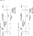
前記第1操作手段対応画像の表示中に前記操作手段が操作された場合には、該操作から第1期間が経過したことに基づいて前記第1操作手段対応画像の表示を終了し(例えば、図16(A)に示すように、操作促進画像として非突出状態のプッシュボタン31Bの画像の表示中にプッシュボタン31Bが操作された場合には、該操作から期間L2が経過したタイミングでプッシュボタン31Bの画像を消去する部分)、
前記第2操作手段対応画像の表示中に前記操作手段が操作された場合には、該操作から前記第1期間とは異なる第2期間が経過したことに基づいて前記第2操作手段対応画像の表示を終了する(例えば、図16(B)に示すように、操作促進画像として突出状態のプッシュボタン31Bの画像の表示中にプッシュボタン31Bが操作された場合には、該操作から期間L3が経過したタイミングでプッシュボタン31Bの画像を消去する部分)
ことを特徴としている。
The gaming machine of the means A is
A gaming machine that can play games,
Operating means operable by the player;
A first operation means corresponding image which is an image for prompting a player to operate the operation means, and a second operation means corresponding image corresponding to the operation means, or a second image different from the first operation means corresponding image Display means capable of displaying an operation means corresponding image;
A suggestion effect suggesting that the control unit is controlled to be in an advantageous state when the operation unit is operated regardless of whether the image corresponding to the first operation unit or the image corresponding to the second operation unit is being displayed. Suggestion effect execution means capable of executing
A specific effect execution means capable of executing a specific effect,
An effect movable body operable based on the operation of the operating means,
When the operating means is operated during the display of the first operating means corresponding image, the display of the first operating means corresponding image is terminated based on a lapse of a first period from the operation;
When the operating means is operated during the display of the second operating means corresponding image, the display of the second operating means corresponding image is performed based on a lapse of a second period different from the first period from the operation. Ends,
A ratio at which the suggestion effect is executed when the operation unit is operated during the display of the first operation unit corresponding image and when the operation unit is operated during the display of the second operation unit corresponding image. Are different,
The first operation unit corresponding image or the second operation unit corresponding image is an image whose display starts at the same timing during execution of the specific effect,
The aspect of the operation means includes a first aspect and a second aspect different from the first aspect,
The first operation unit corresponding image is an operation unit corresponding image corresponding to the first aspect,
The second operation unit corresponding image is an operation unit corresponding image corresponding to the second aspect.
It is characterized by:
Furthermore, the gaming machine of the means 1 is:
A gaming machine capable of playing a game (for example, a pachinko gaming machine 1),
Operating means (for example, a push button 31B) operable by a player;
An image for prompting a player to operate the operation unit, and is a first operation unit corresponding image that is an operation unit corresponding image corresponding to the operation unit (for example, an image of the push button 31B in a non-projecting state). Or display means (for example, the effect display device 5) capable of displaying a second operation means-corresponding image (for example, an image of the push button 31B in a protruding state) different from the first operating means-corresponding image;
An effect movable body operable based on the operation of the operating means,
If the operating means is operated during the display of the first operating means corresponding image, the display of the first operating means corresponding image is terminated based on a lapse of a first period from the operation (for example, As shown in FIG. 16A, when the push button 31B is operated while the image of the push button 31B in the non-projecting state is displayed as the operation promoting image, the push button 31B is operated at a timing when the period L2 has elapsed from the operation. 31B image is deleted),
If the operating means is operated during the display of the second operating means corresponding image, the second operating means corresponding image is displayed based on the lapse of a second period different from the first period from the operation. The display is terminated (for example, as shown in FIG. 16B, when the push button 31B is operated while the image of the protruding push button 31B is displayed as the operation promotion image, a period L3 from the operation is not applied. The part where the image of the push button 31B is erased when the elapsed time)
It is characterized by:

の遊技機は、手段1に記載の遊技機であって、
前記操作手段の態様は、第1態様(例えば、非突出状態)と、該第1態様とは異なる第2態様(例えば、突出状態)と、を含み、
前記第1操作手段対応画像は、前記第1態様に対応する操作手段対応画像(例えば、非突出状態のプッシュボタン31Bの画像)であり、
前記第2操作手段対応画像は、前記第2態様に対応する操作手段対応画像(例えば、突出状態のプッシュボタン31Bの画像)である
ことを特徴としている。
この特徴によれば、操作手段の態様に適した操作手段対応画像を表示できる。
Gaming machine hand stage 2, a gaming machine according to the means 1,
The mode of the operating means includes a first mode (for example, a non-projecting state) and a second mode (for example, a protruding state) different from the first mode,
The first operation unit corresponding image is an operation unit corresponding image corresponding to the first aspect (for example, an image of the push button 31B in a non-projecting state),
The image corresponding to the second operation means is an image corresponding to the operation means corresponding to the second aspect (for example, an image of the push button 31B in a protruding state).
According to this feature, it displays the operation means corresponding image suitable for the mode of the operation means.

の遊技機は、手段に記載の遊技機であって、
前記第2期間は、前記第1期間よりも長い期間(例えば、L3>L2)であり、
前記第2期間において特別演出(例えば、操作演出)を実行する特別演出実行手段(例えば、演出制御用CPU120が図15に示す操作後演出実行処理を実行する部分)を更に備える
ことを特徴としている。
この特徴によれば、特別演出に遊技者を注目させることができるので、遊技興趣を向上できる。
Gaming machine Hand stage 3, a gaming machine according to the means 2,
The second period is a period longer than the first period (for example, L3> L2),
It is characterized by further including a special effect execution means (for example, a portion where the effect control CPU 120 executes the after-operation effect execution process shown in FIG. 15) for executing a special effect (for example, after- operation effect) in the second period. I have.
According to this feature, the player can pay attention to the special effect, so that the interest in the game can be improved.

の遊技機は、手段に記載の遊技機であって、
前記特別演出は、前記第2操作手段対応画像が前記第1操作手段対応画像に変化する演出である(例えば、図19に示すように、突出状態のプッシュボタン31Bの画像が非突出状態のプッシュボタン31Bの画像に更新される部分)
ことを特徴としている。
この特徴によれば、可動体の動作に対応して操作手段対応画像の表示態様が変化したことを遊技者が認識し易くなるので、遊技興趣を向上できる。
Gaming machine Hand stage 4, a gaming machine according to the means 3,
The special effect is an effect in which the image corresponding to the second operation means is changed to the image corresponding to the first operation means (for example, as illustrated in FIG. 19, the image of the push button 31 </ b> B in the protruded state is the push in the non-projected state. The part updated to the image of the button 31B)
It is characterized by:
According to this feature, the player can easily recognize that the display mode of the image corresponding to the operation means has changed according to the operation of the movable body, so that the interest in the game can be improved.

段5の遊技機は、段1〜手段4のいずれかに記載の遊技機であって、
前記第2操作手段対応画像は、前記動作演出に対応して前記第1操作手段対応画像に変化可能である(例えば、図19に示すように、可動体400の退避位置から演出位置への移動(落下)に対応して突出状態のプッシュボタン31Bの画像が非突出状態のプッシュボタン31Bの画像に更新される部分)
ことを特徴としている。
この特徴によれば、可動体の動作に対応して操作手段対応画像の表示態様が変化したことを遊技者が認識し易くなるので、遊技興趣を向上できる。
Gaming machine Hand stage 5 is a gaming machine according to any of the hands stage 1 means 4,
The image corresponding to the second operating means can be changed to the image corresponding to the first operating means in accordance with the motion effect (for example, as shown in FIG. 19, the movable body 400 moves from the retracted position to the effected position). (A part where the image of the push button 31B in the protruding state is updated to the image of the push button 31B in the non-protruding state in response to (fall))
It is characterized by:
According to this feature, the player can easily recognize that the display mode of the image corresponding to the operation means has changed according to the operation of the movable body, so that the interest in the game can be improved.

段6の遊技機は、段1〜手段5のいずれかに記載の遊技機であって、
前記表示手段は、前記動作演出に対応して前記操作手段対応画像の表示を終了する(例えば、図16(B)に示すように、可動体400の退避位置から演出位置への移動(落下)に対応してプッシュボタン31Bの画像を演出表示装置5から消去する部分)
ことを特徴としている。
この特徴によれば、動作演出の演出効果を向上できる。
Gaming machine Hand stage 6 is a gaming machine according to any of the hands stage 1 means 5,
The display means terminates the display of the operation means corresponding image in response to the motion effect (for example, as shown in FIG. 16B, the movable body 400 moves from the retracted position to the effect position (falls). (Erasing part of the image of the push button 31B from the effect display device 5 corresponding to the above)
It is characterized by:
According to this feature, the effect of the motion effect can be improved.

段7の遊技機は、手段6に記載の遊技機であって、
前記表示手段は、前記動作演出が開始されてから前記操作手段対応画像の表示を終了する(例えば、図16(B)に示すように、可動体400の退避位置から演出位置への移動(落下)開始後にプッシュボタン31Bの画像を演出表示装置5から消去する部分)
ことを特徴としている。
この特徴によれば、可動体の動作に対応して操作手段対応画像の表示が終了したことを遊技者が認識し易くなるので、遊技興趣を向上できる。
Gaming machine Hand stage 7, a gaming machine according to the means 6,
The display means terminates the display of the operation means corresponding image after the operation effect is started (for example, as shown in FIG. 16B, the movable body 400 moves from the retracted position to the effect position (falls). ) A part for deleting the image of the push button 31B from the effect display device 5 after the start)
It is characterized by:
According to this feature, the player can easily recognize that the display of the operation means corresponding image has been completed in response to the operation of the movable body, so that the interest in the game can be improved.

段8の遊技機は、段1〜手段7のいずれかに記載の遊技機であって、
前記操作手段対応画像は、第1操作手段対応画像(例えば、非突出状態のプッシュボタン31Bの画像)と、該第1操作手段対応画像とは表示態様が異なる第2操作手段対応画像(例えば、突出状態のプッシュボタン31Bの画像)と、を含み、
前記操作手段が操作されたことに基づいて前記動作演出が実行されないとき(例えば、図17に示すように、変動表示結果がはずれである場合)には、前記操作手段が操作されてから第3期間が経過したことに基づいて前記第1操作手段対応画像の表示を終了し(例えば、図17(A)に示すように、プッシュボタン31Bが操作されてから期間L2が経過したタイミングでプッシュボタン31Bの画像を消去する部分)、前記操作手段が操作されてから前記第3期間が経過したことに基づいて前記第2操作手段対応画像の表示を終了する(例えば、図17(B)に示すように、プッシュボタン31Bが操作されてから期間L2が経過したタイミングでプッシュボタン31Bの画像を消去する部分)
ことを特徴としている。
この特徴によれば、動作演出が実行されないときの表示期間を共通とすることができるので、遊技興趣の低下を防ぐことができる。
Gaming machine Hand stage 8 is a gaming machine according to any of the hands stage 1 means 7,
Said operating means corresponding image, first operating means corresponding image (e.g., image of a push button 31B of the non-projecting state), the second operating means corresponding image display mode to the first operation means corresponding images are different (e.g., Image of the push button 31B in the protruding state).
When the motion effect is not executed based on the operation of the operation unit (for example, as shown in FIG. 17, when the fluctuation display result is out of order), the third operation is performed after the operation unit is operated. The display of the first operation unit corresponding image is terminated based on the lapse of the period (for example, as shown in FIG. 17A, the push button is pushed at the timing when the period L2 has elapsed since the push button 31B was operated). portion to erase an image of 31B), and terminates the display of the operating means operated on the basis that the third period has elapsed since the second operating means corresponding image (e.g., FIG. 17 (B) shown in As described above, the portion where the image of the push button 31B is erased at the timing when the period L2 has elapsed since the push button 31B was operated)
It is characterized by:
According to this feature, since the display period when the motion effect is not executed can be made common, it is possible to prevent a decrease in gaming interest.

段9の遊技機は、段1〜手段8のいずれかに記載の遊技機であって、
前記操作手段対応画像は、第1操作手段対応画像(例えば、非突出状態のプッシュボタン31Bの画像)と、該第1操作手段対応画像とは表示態様が異なる第2操作手段対応画像(例えば、突出状態のプッシュボタン31Bの画像)と、を含み、
前記操作手段が操作されたことに基づいて前記動作演出が実行される場合(例えば、変動表示結果が大当たりである場合)には、第1態様にて前記第2操作手段対応画像の表示を終了し(例えば、図16(B)に示すように、プッシュボタン31Bが操作されてから期間L3に亘って突出状態のプッシュボタン31Bの画像を非突出状態のプッシュボタン31Bの画像に更新し、該更新後の非突出状態のプッシュボタン31Bの画像を演出表示装置5から消去する部分)、
前記操作手段が操作されたことに基づいて前記動作演出が実行されない場合(例えば、変動表示結果がはずれである場合)には、前記第1態様とは異なる第2態様にて前記第2操作手段対応画像の表示を終了する(例えば、図17(B)に示すように、プッシュボタン31Bが操作されてから期間L2が経過したタイミングで突出状態のプッシュボタン31Bの画像を演出表示装置5から消去する部分)
ことを特徴としている。
この特徴によれば、操作手段が操作されたことに基づいて動作演出が実行される場合と実行されない場合とで第2操作手段対応画像の表示を終了する態様が異なることによって、遊技興趣を向上できる。
Gaming machine Hand stage 9, a gaming machine according to any of the hands stage 1 means 8,
Said operating means corresponding image, first operating means corresponding image (e.g., image of a push button 31B of the non-projecting state), the second operating means corresponding image display mode to the first operation means corresponding images are different (e.g., Image of the push button 31B in the protruding state).
When the motion effect is executed based on the operation of the operation means (for example, when the fluctuation display result is a big hit), the display of the second operation means corresponding image is ended in the first mode. (For example, as shown in FIG. 16B, the image of the push button 31B in the protruding state is updated to the image of the push button 31B in the non-protruding state over a period L3 after the push button 31B is operated. A part for deleting the image of the push button 31B in the non-projecting state after the update from the effect display device 5);
When the motion effect is not executed based on the operation of the operation means (for example, when the variable display result is out of order), the second operation means is in a second mode different from the first mode. The display of the corresponding image is terminated (for example, as shown in FIG. 17B, the image of the protruding push button 31B is erased from the effect display device 5 at the timing when the period L2 has elapsed since the push button 31B was operated. Part)
It is characterized by:
According to this feature, by embodiments to terminate the display of the second operation means correspond images in the case of not executed and when the operation effect is executed based on the operation means is operated differs, improved game amusement it can.

段10の遊技機は、段1〜手段9のいずれかに記載の遊技機であって、
前記操作手段対応画像は、第1操作手段対応画像(例えば、変形例2における非突出状態のプッシュボタン31Bの画像)と、該第1操作手段対応画像とは表示開始タイミングが異なる第2操作手段対応画像(例えば、変形例2における突出状態のプッシュボタン31Bの画像)と、を含み、
前記第1操作手段対応画像が表示されている場合は、前記操作手段が操作されたことに基づいて前記第1操作手段対応画像の表示を第1態様にて終了し、
前記第2操作手段対応画像が表示されている場合は、前記操作手段が操作されたことに基づいて前記第2操作手段対応画像の表示を前記第1態様とは異なる第2態様にて終了する(例えば、変形例2に示すように、突出状態のプッシュボタン31Bの画像が表示されているときにプッシュボタン31Bが操作されたことに基づいて該突出状態のプッシュボタン31Bの画像を消去する態様と、非突出状態のプッシュボタン31Bの画像が表示されているときにプッシュボタン31Bが操作されたことに基づいて該非突出状態のプッシュボタン31Bの画像を消去する態様と、が異なる部分)
ことを特徴としている。
この特徴によれば、操作手段対応画像の表示開始タイミングに応じて操作手段対応画像の表示の終了態様が異なることによって遊技興趣を向上できる。
Gaming machine Hand stage 10, a gaming machine according to any of the hands stage 1 means 9,
It said operating means corresponding image, first operating means corresponding image (e.g., image of a push button 31B of the non-projecting state in the modification 2) and a second operating means display start timing is different from the first operating means corresponding image A corresponding image (for example, an image of the push button 31 </ b> B in the protruding state in Modification Example 2),
When said first operation means corresponding image is displayed, the display of the first operation means corresponding images completed in the first aspect on the basis of said operation means is operated,
When the second operating means corresponding image is displayed, ends at a different second aspect and the first aspect of the display of the second operation means corresponding image on the basis of said operating means is operated (For example, as shown in Modification 2, a mode in which the image of the push button 31B in the protruding state is erased based on the operation of the push button 31B while the image of the push button 31B in the protruding state is displayed. And a mode in which the image of the non-projected push button 31B is erased based on the operation of the push button 31B when the image of the non-projected push button 31B is displayed.)
It is characterized by:
According to this feature, the display termination mode of the operation means corresponding image according to the display start timing of the operation means corresponding image can be improved game amusement by different.

段11の遊技機は、段1〜手段10のいずれかに記載の遊技機であって、
遊技者の動作を検出可能な検出手段(例えば、プッシュボタン31B)と、
前記検出手段に対応した特定表示を行う特定表示実行手段(例えば、演出表示装置5)と、
を備え、
前記特定表示実行手段は、第1操作手段対応画像(例えば、非突出状態のプッシュボタン31Bの画像)と、該第1操作手段対応画像とは表示態様が異なる操作手段対応画像であって、該第1操作手段対応画像よりも遊技者にとって有利度が高い第2操作手段対応画像(例えば、非突出状態のプッシュボタン31Bの画像)と、を含み、
前記第1操作手段対応画像を表示した後、該第1操作対応画像に作用する作用演出が実行されることにより前記第2操作手段対応画像を表示可能である(例えば、変形例1として図20に示すように、作用演出に応じて非突出状態のプッシュボタン31Bの画像を突出状態のプッシュボタン31Bの画像に変化させる部分)
ことを特徴としている。
この特徴によれば、作用演出が実行されることによって第1操作手段対応画像が第2操作手段対応画像に変化することが解り易くなるので、演出効果を向上できる。
Gaming machine Hand stage 11, a gaming machine according to any of the hands stage 1 means 10,
Detecting means (for example, a push button 31B) capable of detecting an action of the player;
A specific display execution unit (for example, effect display device 5) for performing a specific display corresponding to the detection unit;
With
The specific display execution unit is a first operation unit corresponding image (for example, an image of the push button 31B in a non-projecting state) and an operation unit corresponding image having a different display mode from the first operation unit corresponding image. A second operation means corresponding image (for example, an image of the push button 31B in a non-projecting state) having a higher degree of advantage for the player than the first operation means corresponding image,
After displaying the image corresponding to the first operation means , an effect effect acting on the image corresponding to the first operation is executed, whereby the image corresponding to the second operation means can be displayed (for example, FIG. As shown in the figure, a portion that changes the image of the push button 31B in the non-projected state to the image of the push button 31B in the projected state according to the action effect)
It is characterized by:
According to this feature, it is easy to understand that the first operation means corresponding image is changed to the second operation means corresponding image by executing the action effect, so that the effect can be improved.

尚、本発明は、本発明の請求項に記載された発明特定事項のみを有するものであって良いし、本発明の請求項に記載された発明特定事項とともに該発明特定事項以外の構成を有するものであっても良い。   It should be noted that the present invention may have only the matters specifying the invention described in the claims of the present invention, or may have configurations other than the matters specifying the invention together with the matters specifying the invention described in the claims of the present invention. It may be something.

パチンコ遊技機を正面から見た正面図である。It is the front view which looked at the pachinko gaming machine from the front. パチンコ遊技機の回路構成例を示すブロック図である。It is a block diagram showing an example of a circuit configuration of a pachinko gaming machine. (A),(B)は、演出制御コマンドを例示する図である。(A), (B) is a figure which illustrates the production control command. 各乱数を示す説明図である。FIG. 4 is an explanatory diagram showing each random number. 変動パターンを例示する図である。It is a figure which illustrates a fluctuation pattern. 表示結果判定テーブルを示す説明図である。It is an explanatory view showing a display result judgment table. (A)は、大当り種別判定テーブルの構成例を示す図であり、(B)は、各種大当りの内容を示す図である。(A) is a figure which shows the example of a structure of a big hit type determination table, (B) is a figure which shows the content of various big hits. 遊技制御用タイマ割込み処理の一例を示すフローチャートである。It is a flowchart which shows an example of the timer interrupt processing for game control. 特別図柄プロセス処理の一例を示すフローチャートである。It is a flow chart which shows an example of special design process processing. 演出制御メイン処理の一例を示すフローチャートである。It is a flow chart which shows an example of production control main processing. 演出制御プロセス処理の一例を示すフローチャートである。It is a flowchart which shows an example of effect control process processing. 演出図柄変動開始処理の一例を示すフローチャートである。It is a flowchart which shows an example of an effect symbol change start process. プッシュボタンの突出決定割合を示す図である。It is a figure which shows the protrusion determination ratio of a push button. 演出図柄変動中処理の一例を示すフローチャートである。It is a flowchart which shows an example of a process during a production symbol change. 操作後演出実行処理の一例を示すフローチャートである。It is a flowchart which shows an example of the post-operation effect execution processing. (A)は、プッシュボタンの突出無しで大当りとなる場合のリーチ演出におけるタイミングチャートであり、(B)は、プッシュボタンの突出有りで大当りとなる場合のリーチ演出におけるタイミングチャートである。(A) is a timing chart in a reach effect when a big hit occurs without the push button protruding, and (B) is a timing chart in a reach effect when a big hit occurs with the push button protruding. (A)は、プッシュボタンの突出無しではずれとなる場合のリーチ演出におけるタイミングチャートであり、(B)は、プッシュボタンの突出有りではずれとなる場合のリーチ演出におけるタイミングチャートである。(A) is a timing chart in a reach effect in the case of a shift without the push button protruding, and (B) is a timing chart in a reach effect in the case of a shift with the push button protruding. リーチ演出での演出表示装置の表示態様及び可動役物の動作態様を示す図である。It is a figure showing a display mode of an effect display device in a reach effect, and an operation mode of a movable character. リーチ演出での演出表示装置の表示態様及び可動役物の動作態様を示す図である。It is a figure showing a display mode of an effect display device in a reach effect, and an operation mode of a movable character. 変形例1におけるリーチ演出での演出表示装置の表示態様及び可動役物の動作態様を示す図である。It is a figure which shows the display aspect of the effect display device in the reach effect in the modification 1, and the operation aspect of a movable role.

本発明に係る遊技機を実施するための形態を実施例に基づいて以下に説明する。   Embodiments for implementing a gaming machine according to the present invention will be described below based on embodiments.

まず、遊技機の一例であるパチンコ遊技機1の全体の構成について説明する。尚、以下の説明にて、図1の手前側をパチンコ遊技機1の前方(前面、正面)側、奥側を後方(背面)側として説明する。尚、本実施例でパチンコ遊技機1の前面とは、遊技者側からパチンコ遊技機1を見たときに該遊技者と対向する対向面である。尚、フローチャートの各ステップの説明にて、例えば「ステップS1」と記載する箇所を「S1」と略記する場合がある。また、本実施例で『実行』と『実施』とは同義である。   First, the overall configuration of the pachinko gaming machine 1 as an example of the gaming machine will be described. In the following description, the front side of FIG. 1 will be described as the front (front, front) side of the pachinko gaming machine 1, and the back side will be described as the rear (back) side. In this embodiment, the front surface of the pachinko gaming machine 1 is an opposing surface that faces the player when the pachinko gaming machine 1 is viewed from the player side. In the description of each step of the flowchart, for example, a portion described as “Step S1” may be abbreviated as “S1”. In this embodiment, “execute” and “implement” are synonymous.

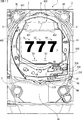
図1は、本実施例のパチンコ遊技機1の正面図であり、主要部材の配置レイアウトを示す。パチンコ遊技機1(以下、遊技機と略記する場合がある)は、大別して、遊技盤面を構成する遊技盤2(ゲージ盤)と、遊技盤2を支持固定する遊技機用枠3(台枠)とから構成されている。遊技盤2には、ガイドレールによって囲まれた、ほぼ円形状の遊技領域が形成されている。遊技領域には、遊技球が打球発射装置から発射されて打ち込まれる。   FIG. 1 is a front view of the pachinko gaming machine 1 of the present embodiment, and shows an arrangement layout of main members. The pachinko gaming machine 1 (hereinafter sometimes abbreviated as a gaming machine) is roughly divided into a gaming board 2 (gauge board) constituting a gaming board surface, and a gaming machine frame 3 (base frame) for supporting and fixing the gaming board 2. ). The game board 2 has a substantially circular game area surrounded by guide rails. In the game area, a game ball is fired and hit from a hit ball firing device.

遊技盤2の所定位置(図1に示す例では、遊技領域の右側方)には、第1特別図柄表示器4Aと、第2特別図柄表示器4Bとが設けられている。第1特別図柄表示器4Aと第2特別図柄表示器4Bはそれぞれ、例えば7セグメントやドットマトリクスのLED(発光ダイオード)等から構成され、変動表示ゲームの一例となる特図ゲームにて、各々を識別可能な複数種類の識別情報(特別識別情報)である特別図柄(「特図」ともいう)が、変動可能に表示(変動表示または可変表示ともいう)される。例えば、第1特別図柄表示器4Aと第2特別図柄表示器4Bはそれぞれ、「0」〜「9」を示す数字や「−」を示す記号等から構成される複数種類の特別図柄を変動表示する。尚、第1特別図柄表示器4Aや第2特別図柄表示器4Bにて表示される特別図柄は、「0」〜「9」を示す数字や「−」を示す記号等から構成されるものに限定されず、例えば7セグメントのLEDで点灯させるものと消灯させるものとの組合せを異ならせた複数種類の点灯パターンが、複数種類の特別図柄として予め設定されていればよい。以下では、第1特別図柄表示器4Aにて変動表示される特別図柄を「第1特図」ともいい、第2特別図柄表示器4Bにて変動表示される特別図柄を「第2特図」ともいう。   A first special symbol display 4A and a second special symbol display 4B are provided at predetermined positions of the game board 2 (to the right of the game area in the example shown in FIG. 1). Each of the first special symbol display 4A and the second special symbol display 4B is composed of, for example, a 7-segment or dot matrix LED (light emitting diode). Special symbols (also referred to as “special figures”), which are a plurality of types of identification information that can be identified (special identification information), are variably displayed (also referred to as variable display or variable display). For example, each of the first special symbol display 4A and the second special symbol display 4B variably displays a plurality of types of special symbols composed of numbers indicating "0" to "9", symbols indicating "-", and the like. I do. The special symbols displayed on the first special symbol display 4A and the second special symbol display 4B are composed of numerals indicating "0" to "9" and symbols indicating "-". The present invention is not limited to this. For example, it is only necessary that a plurality of types of lighting patterns in which a combination of ones to be turned on by a 7-segment LED and ones to be turned off are set in advance as a plurality of types of special symbols. In the following, a special symbol variably displayed on the first special symbol display 4A is also referred to as a "first special symbol", and a special symbol variably displayed on the second special symbol indicator 4B is a "second special symbol". Also called.

第1特別図柄表示器4Aと第2特別図柄表示器4Bはともに、例えば方形状に形成されている。尚、第1特図の種類と第2特図の種類は同じ(例えば、ともに「0」〜「9」を示す数字、及び、「−」を示す記号)であってもよいし、種類が異なっていてもよい。また、第1特別図柄表示器4Aと第2特別図柄表示器4Bはそれぞれ、例えば「00」〜「99」を示す数字(あるいは2桁の記号)を変動表示するように構成されていてもよいし、これら「00」〜「99」を示す各セグメントが、「00」〜「99」を視認不能にランダムに配置された表示器により変動表示するように構成されていてもよい。   The first special symbol display 4A and the second special symbol display 4B are both formed in, for example, a square shape. Note that the type of the first special map and the type of the second special map may be the same (for example, both numbers indicating “0” to “9” and a symbol indicating “−”), and the type may be different. It may be different. Further, the first special symbol display 4A and the second special symbol display 4B may be configured to variably display, for example, numbers (or two-digit symbols) indicating “00” to “99”. Each of the segments “00” to “99” may be configured so that “00” to “99” are variably displayed by a display device that is randomly arranged invisibly.

遊技盤2の遊技領域の中央付近には、演出表示装置5が設けられている。演出表示装置5は、例えばLCD(液晶表示装置)等から構成され、各種の演出画像を表示する表示領域を形成している。演出表示装置5の表示領域では、第1特別図柄表示器4Aによる第1特図の変動表示や第2特別図柄表示器4Bによる第2特図の変動表示のそれぞれに対応して、例えば3つといった複数の変動表示部となる演出図柄表示エリアにて、各々を識別可能な複数種類の識別情報(装飾識別情報)である演出図柄(飾り図柄ともいう)が変動表示される。この演出図柄の変動表示も、変動表示ゲームに含まれる。   An effect display device 5 is provided near the center of the game area of the game board 2. The effect display device 5 includes, for example, an LCD (liquid crystal display device) or the like, and forms a display area for displaying various effect images. In the display area of the effect display device 5, for example, three display patterns corresponding to the variable display of the first special figure by the first special symbol display 4A and the variable display of the second special figure by the second special symbol display 4B are provided. In the effect symbol display area serving as a plurality of variable display portions, an effect symbol (also referred to as a decorative symbol), which is a plurality of types of identification information (decoration identification information) that can be identified, is displayed in a variable manner. The variation display of the effect symbol is also included in the variation display game.

一例として、演出表示装置5の表示領域には、「左」、「中」、「右」の演出図柄表示エリア5L,5C,5Rが配置されている。そして、第1特別図柄表示器4Aでの第1特図の変動と第2特別図柄表示器4Bでの第2特図の変動のうち、いずれかが開始されることに対応して、「左」、「中」、「右」の各演出図柄表示エリア5L,5C,5Rにて演出図柄の変動(例えば上下方向のスクロール表示)が開始される。その後、演出表示装置5の「左」、「中」、「右」の各演出図柄表示エリア5L,5C,5Rにて、確定演出図柄(最終停止図柄)が停止表示される。   As an example, in the display area of the effect display device 5, “left”, “middle”, and “right” effect symbol display areas 5L, 5C, and 5R are arranged. Then, in response to the start of one of the change of the first special figure on the first special symbol display 4A and the change of the second special figure on the second special symbol display 4B, "left In the effect symbol display areas 5L, 5C, 5R of "," "medium," and "right," the variation of the effect symbols (for example, vertical scroll display) is started. Thereafter, the fixed effect symbols (final stop symbols) are stopped and displayed in the effect symbol display areas 5L, 5C, 5R of "left", "middle", and "right" of the effect display device 5.

このように、演出表示装置5の表示領域では、第1特別図柄表示器4Aでの第1特図を用いた特図ゲーム、または、第2特別図柄表示器4Bでの第2特図を用いた特図ゲームと同期して、各々が識別可能な複数種類の演出図柄の変動表示を行い、確定演出図柄を導出表示(あるいは単に「導出」ともいう)する。尚、演出図柄の変動表示中に変動表示が仮停止するようにしても良い。   As described above, in the display area of the effect display device 5, a special figure game using the first special figure on the first special symbol display 4A or a second special figure on the second special symbol display 4B is used. In synchronism with the special figure game, a plurality of different types of effect symbols, each of which is identifiable, are displayed in a fluctuating manner, and the definite effect symbols are derived and displayed (or simply referred to as “derived”). Note that the fluctuation display may temporarily stop during the fluctuation display of the effect symbol.

「左」、「中」、「右」の各演出図柄表示エリア5L,5C,5Rにて変動表示される演出図柄には、例えば8種類の図柄(英数字「1」〜「8」あるいは漢数字や、英文字、所定のモチーフに関連する8個のキャラクタ画像、数字や文字あるいは記号とキャラクタ画像との組合せなどであればよく、キャラクタ画像は、例えば人物や動物、これら以外の物体、もしくは、文字などの記号、あるいは、その他の任意の図形を示す飾り画像であればよい)で構成される。演出図柄のそれぞれには、対応する図柄番号が付されている。例えば、「1」〜「8」を示す英数字それぞれに対して、「1」〜「8」の図柄番号が付されている。尚、演出図柄は8種類に限定されず、「大当り」となる組合せや「はずれ」となる組合せなど適当な数の組合せを構成可能であれば、何種類であってもよい(例えば7種類や9種類など)。   For example, eight types of symbols (alphanumeric characters "1" to "8" or Chinese characters) are displayed in the variation symbol display areas 5L, 5C, and 5R of "left," "middle," and "right." Numbers, English characters, eight character images related to a predetermined motif, any combination of numbers and characters or symbols and character images, etc., may be a character image, for example, a person or animal, an object other than these, or , A symbol such as a character, or any other decorative image indicating an arbitrary figure). Each of the effect symbols is given a corresponding symbol number. For example, symbol numbers "1" to "8" are assigned to alphanumeric characters indicating "1" to "8", respectively. Note that the effect design is not limited to eight types, and may be any type as long as an appropriate number of combinations such as "big hit" combinations and "losing" combinations can be configured. 9 types).

演出図柄の変動表示が開始された後、確定演出図柄が導出表示されるまでには、「左」、「中」、「右」の各演出図柄表示エリア5L,5C,5R、又は、演出図柄表示エリア5L,5C,5Rのうち少なくともいずれか1つ(例えば「左」の演出図柄表示エリア5Lなど)にて、例えば図柄番号が小さいものから大きいものへと順次に上方から下方へと流れるようなスクロール表示が行われ、図柄番号が最大(例えば「8」)である演出図柄が表示されると、続いて図柄番号が最小(例えば「1」)である演出図柄が表示される。   After the display of the variation of the effect symbol is started, the effect symbol display area 5L, 5C, 5R of “left”, “middle”, “right” or the effect symbol is displayed until the definite effect symbol is derived and displayed. In at least one of the display areas 5L, 5C, and 5R (for example, the “left” effect symbol display area 5L, etc.), for example, the symbol numbers sequentially flow from upper to lower, from small to large. When the effect design with the highest symbol number (for example, “8”) is displayed and then the effect symbol with the smallest symbol number (for example, “1”) is displayed.

演出表示装置5の表示領域の下部の左右2箇所には、第1保留記憶表示エリア5D、第2保留記憶表示エリア5Uが設定されている。第1保留記憶表示エリア5D、第2保留記憶表示エリア5Uでは、特図ゲームに対応した変動表示の保留記憶数(特図保留記憶数)を特定可能に表示する保留記憶表示が行われる。   A first hold storage display area 5D and a second hold storage display area 5U are set at two lower left and right portions of the display area of the effect display device 5. In the first hold storage display area 5D and the second hold storage display area 5U, a hold storage display is performed in which the number of change storages corresponding to the special figure game (number of special figure hold storages) can be specified.

ここで、特図ゲームに対応した変動表示の保留は、普通入賞球装置6Aが形成する第1始動入賞口や、普通可変入賞球装置6Bが形成する第2始動入賞口を、遊技球が通過(進入)することによる始動入賞に基づいて発生する。即ち、特図ゲームや演出図柄の変動表示といった変動表示ゲームを実行するための始動条件(「実行条件」ともいう)は成立したが、先に成立した開始条件に基づく変動表示ゲームが実行中であることやパチンコ遊技機1が大当り遊技状態に制御されていることなどにより、変動表示ゲームの開始を許容する開始条件が成立していないときに、成立した始動条件に対応する変動表示の保留が行われる。本実施例では、第1始動入賞口を遊技球が通過(進入)することによる始動入賞に基づいて発生した保留記憶表示と第2始動入賞口を遊技球が通過(進入)することによる始動入賞に基づいて発生した保留記憶表示とを丸型の白色表示とする。   Here, the suspension of the variable display corresponding to the special figure game is such that the game ball passes through the first starting winning opening formed by the ordinary winning ball device 6A or the second starting winning opening formed by the ordinary variable winning ball device 6B. This occurs based on a start winning prize due to (entering). That is, a start condition (also referred to as an “execution condition”) for executing a variable display game such as a special figure game or a variable display of effect symbols is satisfied, but the variable display game based on the previously established start condition is being executed. Due to the fact that the pachinko gaming machine 1 is controlled to the big hit gaming state, when the start condition allowing the start of the variable display game is not established, the suspension of the variable display corresponding to the established start condition is performed. Done. In the present embodiment, a hold storage display generated based on a start winning due to a game ball passing (entering) the first starting winning opening and a start winning due to a game ball passing (entering) the second starting winning opening. And the hold storage display generated on the basis of the white color display.

尚、以下の説明では、第1保留記憶表示エリア5D、第2保留記憶表示エリア5Uでの表示を保留表示と総称することがある。   In the following description, the display in the first hold storage display area 5D and the second hold storage display area 5U may be collectively referred to as hold display.

図1に示す例では、保留記憶表示エリアとともに、第1特別図柄表示器4A及び第2特別図柄表示器4Bの上部と下部に、特図保留記憶数を特定可能に表示するための第1保留表示器25Aと第2保留表示器25Bとが設けられている。第1保留表示器25Aは、第1特図保留記憶数を特定可能に表示する。第2保留表示器25Bは、第2特図保留記憶数を特定可能に表示する。第1特図保留記憶数と第2特図保留記憶数とを加算した変動表示の保留記憶数は、特に、合計保留記憶数ともいう。   In the example shown in FIG. 1, the first holding for displaying the number of special figure holding storages in the upper and lower portions of the first special symbol display 4A and the second special symbol display 4B together with the holding storage display area so as to be identifiable. An indicator 25A and a second hold indicator 25B are provided. The first reservation display 25A displays the first special figure reservation storage number in a identifiable manner. The second reservation display 25B displays the second special figure reservation storage number in a identifiable manner. In particular, the number of suspended storages in the variable display obtained by adding the first special figure suspended storage number and the second special figure suspended storage number is also referred to as a total suspended storage number.

演出表示装置5の下方には、普通入賞球装置6Aと、普通可変入賞球装置6Bとが設けられている。普通入賞球装置6Aは、例えば所定の玉受部材によって常に一定の開放状態に保たれる第1始動入賞口を形成する。普通可変入賞球装置6Bは、図2に示す普通電動役物用となるソレノイド81によって、垂直位置となる通常開放状態と傾動位置となる拡大開放状態とに変化する一対の可動翼片を有する電動チューリップ型役物(普通電動役物)を備え、第2始動入賞口を形成する。   Below the effect display device 5, a normal winning ball device 6A and a normal variable winning ball device 6B are provided. The normal winning prize ball device 6A forms a first starting winning opening that is always kept in a fixed open state by a predetermined ball receiving member, for example. The normally variable winning ball device 6B is an electric motor having a pair of movable wing pieces that change between a normal open state, which is a vertical position, and an enlarged open state, which is a tilt position, by a solenoid 81 for a normal electric accessory shown in FIG. A tulip-type accessory (normally an electric accessory) is provided to form a second starting winning opening.

一例として、普通可変入賞球装置6Bでは、普通電動役物用のソレノイド81がオフ状態であるときに可動翼片が垂直位置となることにより、遊技球が第2始動入賞口を通過(進入)しがたい通常開放状態となる。その一方で、普通可変入賞球装置6Bでは、普通電動役物用のソレノイド81がオン状態であるときに可動翼片が傾動位置となる傾動制御により、遊技球が第2始動入賞口を通過(進入)しやすい拡大開放状態となる。尚、普通可変入賞球装置6Bは、通常開放状態であるときでも、第2始動入賞口には遊技球が進入可能であるものの、拡大開放状態であるときよりも遊技球が進入する可能性が低くなるように構成してもよい。あるいは、普通可変入賞球装置6Bは、通常開放状態にて、例えば第2始動入賞口を閉鎖することなどにより、第2始動入賞口には遊技球が進入しないように構成してもよい。このように、第2始動入賞口は、遊技球が通過(進入)しやすい拡大開放状態と、遊技球が通過(進入)しにくいまたは通過(進入)できない通常開放状態とに変化する。   As an example, in the ordinary variable winning prize ball device 6B, when the solenoid 81 for the ordinary electric accessory is in the off state, the movable wing piece is in the vertical position, so that the game ball passes (enters) the second starting winning opening. It is difficult to open normally. On the other hand, in the ordinary variable winning prize ball device 6B, the game ball passes through the second starting winning opening by the tilting control in which the movable wing piece is in the tilting position when the solenoid 81 for the normal electric accessory is in the ON state ( Into the open state where it is easy to enter. Note that, even when the normally variable winning prize ball device 6B is in the normally open state, although the game ball can enter the second starting winning opening, there is a possibility that the gaming ball enters more than in the enlarged opening state. You may comprise so that it may become low. Alternatively, the normally variable winning prize ball device 6B may be configured such that, for example, by closing the second starting winning opening in the normally opened state, the game ball does not enter the second starting winning opening. As described above, the second start winning opening changes between the enlarged open state in which the game balls easily pass (enter) and the normally open state in which the game balls hardly pass (enter) or cannot pass (enter).

普通入賞球装置6Aに形成された第1始動入賞口を通過(進入)した遊技球は、例えば図2に示す第1始動口スイッチ22Aによって検出される。普通可変入賞球装置6Bに形成された第2始動入賞口を通過(進入)した遊技球は、例えば図2に示す第2始動口スイッチ22Bによって検出される。第1始動口スイッチ22Aによって遊技球が検出されたことに基づき、所定個数(例えば3個)の遊技球が賞球として払い出され、第1特図保留記憶数が所定の上限値(例えば「4」)未満であれば、第1始動条件が成立する。第2始動口スイッチ22Bによって遊技球が検出されたことに基づき、所定個数(例えば3個)の遊技球が賞球として払い出され、第2特図保留記憶数が所定の上限値(例えば「4」)未満であれば、第2始動条件が成立する。尚、第1始動口スイッチ22Aによって遊技球が検出されたことに基づいて払い出される賞球の個数と、第2始動口スイッチ22Bによって遊技球が検出されたことに基づいて払い出される賞球の個数は、互いに同一の個数であってもよいし、異なる個数であってもよい。   A game ball that has passed (entered) a first starting winning opening formed in the normal winning ball device 6A is detected by, for example, a first starting port switch 22A shown in FIG. A game ball that has passed (entered) the second starting winning opening formed in the normal variable winning ball device 6B is detected by, for example, the second starting opening switch 22B shown in FIG. Based on the detection of the game balls by the first start port switch 22A, a predetermined number (for example, three) of game balls are paid out as prize balls, and the first special figure reserved storage number becomes a predetermined upper limit value (for example, “ 4)), the first start condition is satisfied. Based on the detection of the game ball by the second starting port switch 22B, a predetermined number (for example, three) of game balls are paid out as prize balls, and the second special figure reserved storage number is set to a predetermined upper limit value (for example, “ 4)), the second start condition is satisfied. The number of prize balls paid out based on the detection of a game ball by the first starting port switch 22A and the number of prize balls paid out based on the detection of a game ball by the second starting port switch 22B May be the same number or different numbers.

普通入賞球装置6Aと普通可変入賞球装置6Bの下方位置には、特別可変入賞球装置7が設けられている。特別可変入賞球装置7は、図2に示す大入賞口扉用となるソレノイド82によって開閉駆動される大入賞口扉を備え、その大入賞口扉によって開放状態と閉鎖状態とに変化する所定領域としての大入賞口を形成する。   A special variable winning ball device 7 is provided below the normal winning ball device 6A and the normal variable winning ball device 6B. The special variable winning ball device 7 includes a special winning opening door driven by a solenoid 82 serving as a special winning opening door shown in FIG. 2, and a predetermined area that changes between an open state and a closed state by the special winning opening door. As a big winning opening as.

一例として、特別可変入賞球装置7では、大入賞口扉用のソレノイド82がオフ状態であるときに大入賞口扉が大入賞口を閉鎖状態として、遊技球が大入賞口を通過(進入)できなくする。その一方で、特別可変入賞球装置7では、大入賞口扉用のソレノイド82がオン状態であるときに大入賞口扉が大入賞口を開放状態として、遊技球が大入賞口を通過(進入)し易くする。このように、大入賞口は、遊技球が通過(進入)し易く遊技者にとって有利な開放状態と、遊技球が通過(進入)できず遊技者にとって不利な閉鎖状態とに変化する。尚、遊技球が大入賞口を通過(進入)できない閉鎖状態に代えて、あるいは閉鎖状態の他に、遊技球が大入賞口を通過(進入)しにくい一部開放状態を設けてもよい。   As an example, in the special variable winning ball device 7, when the solenoid 82 for the special winning opening door is in the off state, the special winning opening door closes the special winning opening, and the game ball passes (enters) the special winning opening. Disable it. On the other hand, in the special variable winning ball device 7, when the solenoid 82 for the special winning opening door is on, the special winning opening door opens the special winning opening, and the game ball passes through the special winning opening (enters). ). In this way, the special winning opening changes between an open state in which the game balls easily pass (enter) and is advantageous for the player, and a closed state in which the game balls cannot pass (enter) and is disadvantageous for the player. Note that, instead of the closed state in which the game ball cannot pass (enter) the large winning opening, or in addition to the closed state, a partially open state in which the game ball hardly passes (enter) the large winning opening may be provided.

大入賞口を通過(進入)した遊技球は、例えば図2に示すカウントスイッチ23によって検出される。カウントスイッチ23によって遊技球が検出されたことに基づき、所定個数(例えば15個)の遊技球が賞球として払い出される。こうして、開放状態となった特別可変入賞球装置7の大入賞口を遊技球が通過(進入)したときには、他の入賞口(例えば第1始動入賞口や第2始動入賞口)を遊技球が通過(進入)したときよりも多くの賞球が払い出される。従って、特別可変入賞球装置7の大入賞口が開放状態となれば、その大入賞口に遊技球が進入可能となり、遊技者にとって有利な第1状態となる。その一方で、特別可変入賞球装置7の大入賞口が閉鎖状態となれば、大入賞口に遊技球を通過(進入)させて賞球を得ることが不可能または困難になり、遊技者にとって不利な第2状態となる。   A game ball that has passed (entered) the special winning opening is detected by, for example, the count switch 23 shown in FIG. Based on the detection of the game balls by the count switch 23, a predetermined number (for example, 15) of game balls are paid out as prize balls. In this way, when the game ball passes (enters) the large winning opening of the special variable winning ball device 7 which has been opened, the gaming ball is placed in another winning opening (for example, the first starting winning opening or the second starting winning opening). More prize balls are paid out than when passing (entering). Therefore, when the special winning opening of the special variable winning ball device 7 is in an open state, the game balls can enter the special winning opening, and the first state is advantageous to the player. On the other hand, if the special winning opening of the special variable winning ball device 7 is in a closed state, it becomes impossible or difficult for the player to pass (enter) the gaming ball into the special winning opening to obtain the winning prize. The second state is disadvantageous.

また、演出表示装置5の上方には、可動役物400が設けられている。該可動役物400は、可動役物第1駆動モータ301(図2参照)の駆動と図示しない駆動機構によって図1に示す演出表示装置5の上方位置である退避位置と、該退避位置よりも下方であり、パチンコ遊技機1の正面視において演出表示装置5と重畳する演出位置と、の間で垂直移動可能となっている。   Above the effect display device 5, a movable accessory 400 is provided. The movable accessory 400 is driven by a movable accessory first drive motor 301 (see FIG. 2) and a drive mechanism (not shown), and a retracted position which is an upper position of the effect display device 5 shown in FIG. It is downward, and can move vertically between an effect position overlapping with the effect display device 5 when the pachinko gaming machine 1 is viewed from the front.

更に、図1に示すように、可動役物400の左部には第1可動部401が配置されており、可動役物400の右部には第2可動部402が配置されている。第1可動部401は、可動役物400の左右幅方向における中央左部と左端部との間で移動可能に設けられており、第2可動部402は、可動役物400の左右幅方向における中央右部と右端部との間で移動可能に設けられている。特に本実施例の可動役物400は、可動役物第2駆動モータ302(図2参照)の駆動と図示しない駆動機構によって第1可動部401と第2可動部402とが連動して移動することによって、第1可動部401と第2可動部402とが左右幅方向の中央部で近接する近接状態(図1参照)と、第1可動部401と第2可動部402とがそれぞれ可動役物400の左端部と右端部とに移動して離間する離間状態(図19(J)参照)と、に変化可能となっている。尚、本実施例での可動役物400は、退避位置において近接状態にて配置され、演出位置に配置されることによって離間状態に変化するようになっている。   Further, as shown in FIG. 1, a first movable portion 401 is disposed on a left portion of the movable role 400, and a second movable portion 402 is disposed on a right portion of the movable role 400. The first movable portion 401 is provided so as to be movable between a left center portion and a left end portion of the movable accessory 400 in the left-right width direction, and the second movable portion 402 is provided in the left-right width direction of the movable accessory 400. It is provided movably between the center right part and the right end part. In particular, in the movable accessory 400 of the present embodiment, the first movable portion 401 and the second movable portion 402 move in conjunction with the driving of the movable accessory second drive motor 302 (see FIG. 2) and a drive mechanism (not shown). Thus, the first movable portion 401 and the second movable portion 402 are in the proximity state (see FIG. 1) in which the first movable portion 401 and the second movable portion 402 are close to each other at the central portion in the left-right width direction, and the first movable portion 401 and the second movable portion 402 are respectively movable. It can be changed to a separated state (see FIG. 19 (J)) in which the object 400 moves to and separates from the left end and the right end. The movable role 400 in the present embodiment is arranged in a close state at the retreat position, and changes to a separated state by being arranged at the production position.

遊技盤2の所定位置(図1に示す例では、遊技領域の下方)には、普通図柄表示器20が設けられている。一例として、普通図柄表示器20は、第1特別図柄表示器4Aや第2特別図柄表示器4Bと同様に7セグメントやドットマトリクスのLED等から構成され、特別図柄とは異なる複数種類の識別情報である普通図柄(「普図」あるいは「普通図」ともいう)を変動可能に表示(変動表示)する。このような普通図柄の変動表示は、普図ゲーム(「普通図ゲーム」ともいう)と称される。   At a predetermined position of the game board 2 (in the example shown in FIG. 1, below the game area), a normal symbol display 20 is provided. As an example, like the first special symbol display 4A and the second special symbol indicator 4B, the ordinary symbol indicator 20 is composed of a 7-segment or dot matrix LED, and a plurality of types of identification information different from the special symbol. Is displayed (variable display) so as to be variable. Such a variation display of the ordinary symbol is called an ordinary game (also referred to as a “normal game”).

普通図柄表示器20の側方には、普図保留表示器25Cが設けられている。普図保留表示器25Cは、例えば4個のLEDを含んで構成され、通過ゲート41を通過した有効通過球数としての普図保留記憶数を表示する。   On the side of the normal symbol display 20, a normal symbol holding display 25C is provided. The general-purpose reservation indicator 25C is configured to include, for example, four LEDs, and displays the general-purpose reserved storage number as the number of effective passing balls that have passed through the passage gate 41.

遊技盤2の表面には、上記の構成以外にも、遊技球の流下方向や速度を変化させる風車及び多数の障害釘が設けられている。また、第1始動入賞口、第2始動入賞口及び大入賞口とは異なる入賞口として、例えば所定の玉受部材によって常に一定の開放状態に保たれる単一または複数の一般入賞口が設けられてもよい。この場合には、一般入賞口のいずれかに進入した遊技球が所定の一般入賞球スイッチによって検出されたことに基づき、所定個数(例えば10個)の遊技球が賞球として払い出されればよい。遊技領域の最下方には、いずれの入賞口にも進入しなかった遊技球が取り込まれるアウト口が設けられている。   On the surface of the game board 2, in addition to the above-described configuration, a windmill for changing the flowing direction and speed of the game ball and a number of obstacle nails are provided. Further, as a winning opening different from the first starting winning opening, the second starting winning opening, and the big winning opening, for example, a single or a plurality of general winning openings that are always kept in a fixed open state by a predetermined ball receiving member are provided. You may be. In this case, a predetermined number (for example, 10) of game balls may be paid out as prize balls based on detection of a game ball that has entered any of the general prize holes by a predetermined general prize ball switch. At the bottom of the game area, there is provided an out port for taking in a game ball that has not entered any of the winning ports.

遊技機用枠3の左右上部位置には、効果音等を再生出力するためのスピーカ8L,8Rが設けられており、更に遊技領域周辺部には、演出用LED9が設けられている。   Speakers 8L and 8R for reproducing and outputting sound effects and the like are provided at upper left and right positions of the gaming machine frame 3, and effect LEDs 9 are provided around the gaming area.

遊技機用枠3の右下部位置には、遊技球を遊技領域に向けて発射するために遊技者等によって操作される打球操作ハンドル(操作ノブ)が設けられている。例えば、打球操作ハンドルは、遊技者等による操作量(回転量)に応じて遊技球の弾発力を調整する。打球操作ハンドルには、打球発射装置が備える発射モータの駆動を停止させるための単発発射スイッチや、タッチリング(タッチセンサ)が設けられていればよい。   At a lower right position of the gaming machine frame 3, a hit ball operation handle (operation knob) operated by a player or the like to fire a game ball toward a game area is provided. For example, the hit ball operation handle adjusts the resilience of a game ball in accordance with the amount of operation (the amount of rotation) by a player or the like. The hitting operation handle may be provided with a single-shot firing switch for stopping driving of a firing motor included in the hitting ball firing device, or a touch ring (touch sensor).

遊技領域下方の遊技機用枠3の所定位置には、賞球として払い出された遊技球や貸し出しによって払い出された遊技球を、打球発射装置へと供給可能に保持(貯留)する上皿(打球供給皿)が設けられている。遊技機用枠3の下部には、上皿から溢れた余剰球などを、パチンコ遊技機1の外部へと排出可能に保持(貯留)する下皿(図示略)が設けられている。   At a predetermined position of the gaming machine frame 3 below the game area, an upper plate for holding (reserving) game balls paid out as prize balls or game balls paid out by lending so that they can be supplied to a hit ball launching device. (A hit ball supply tray) is provided. A lower plate (not shown) is provided below the gaming machine frame 3 for holding (storing) surplus balls and the like overflowing from the upper plate so as to be discharged to the outside of the pachinko gaming machine 1.

また、上皿には、遊技機の前方に膨出する膨出部30が形成されており、該膨出部30の上面には、遊技者が操作可能なプッシュボタン31Bが設けられている。本実施例のプッシュボタン31Bは、ボタン駆動モータ303(図2参照)の駆動と図示しない駆動機構によって膨出部30内に収納されている非突出状態と該非突出状態よりも膨出部30の上方に向けて突出する突出状態とに変化可能に設けられており、遊技者は、これら非突出状態のプッシュボタン31Bと突出状態のプッシュボタン31Bとを操作可能となっている。プッシュボタン31Bは、遊技者からの押下動作を、機械的、電気的、あるいは、電磁的に、検出できるように構成されていればよい。プッシュボタン31Bの配置位置における上皿の本体内部などには、プッシュボタン31Bに対してなされた遊技者による押下動作を検出するプッシュセンサ35Bが設けられていればよい。   Further, a bulging portion 30 bulging forward of the gaming machine is formed on the upper plate, and a push button 31B operable by a player is provided on the upper surface of the bulging portion 30. The push button 31B according to the present embodiment includes a non-projecting state housed in the bulging portion 30 by driving a button driving motor 303 (see FIG. 2) and a driving mechanism (not shown), and a bulging portion 30 that is higher than the non-protruding state. The push button 31B in the non-projecting state and the push button 31B in the projecting state can be operated by the player. The push button 31B only needs to be configured to be able to mechanically, electrically, or electromagnetically detect a pressing operation from a player. A push sensor 35B may be provided inside the main body of the upper plate at the position where the push button 31B is arranged, for example, to detect a pressing operation performed by the player on the push button 31B.

パチンコ遊技機1には、例えば、図2に示すような主基板11、演出制御基板12、音声制御基板13、LED制御基板14といった、各種の制御基板が搭載されている。また、パチンコ遊技機1には、主基板11と演出制御基板12との間で伝送される各種の制御信号を中継するための中継基板15なども搭載されている。その他にも、遊技盤2などの背面には、例えば払出制御基板、情報端子基板、発射制御基板、インタフェース基板、電源基板などといった、各種の基板が配置されている。   The pachinko gaming machine 1 has mounted thereon various control boards such as a main board 11, an effect control board 12, a sound control board 13, and an LED control board 14 as shown in FIG. The pachinko gaming machine 1 is also provided with a relay board 15 for relaying various control signals transmitted between the main board 11 and the effect control board 12. In addition, various boards such as a payout control board, an information terminal board, a launch control board, an interface board, and a power board are arranged on the back surface of the game board 2 and the like.

主基板11は、メイン側の制御基板であり、パチンコ遊技機1での遊技の進行を制御するための各種回路が搭載されている。主基板11は、主として、特図ゲームにて用いる乱数の設定機能、所定位置に配設されたスイッチ等からの出力信号を入力可能とする機能、演出制御基板12などからなるサブ側の制御基板に宛てて、指令情報の一例となる制御コマンドを制御信号として出力して送信する機能、外部に各種情報を出力する機能などを備えている。また、主基板11は、第1特別図柄表示器4Aと第2特別図柄表示器4Bを構成する各LED(例えばセグメントLED)などの点灯/消灯制御を行って第1特図や第2特図の変動表示を制御することや、普通図柄表示器20の点灯/消灯/発色制御などを行って普通図柄表示器20による普通図柄の変動表示を制御することといった、所定の表示図柄の変動表示を制御する機能も備えている。   The main board 11 is a control board on the main side, on which various circuits for controlling the progress of the game in the pachinko gaming machine 1 are mounted. The main board 11 mainly has a function of setting a random number used in a special figure game, a function of enabling input of an output signal from a switch or the like disposed at a predetermined position, and a sub-side control board including an effect control board 12 and the like. , A function of outputting a control command as an example of command information as a control signal and transmitting the same, a function of outputting various types of information to the outside, and the like. In addition, the main board 11 performs lighting / extinguishing control of each LED (for example, segment LED) constituting the first special symbol display 4A and the second special symbol display 4B to perform the first special figure and the second special figure. The display of the variation of a predetermined display symbol, such as controlling the variation display of the symbol, and controlling the variation of the ordinary symbol by the ordinary symbol display 20 by performing lighting / off / coloring control of the ordinary symbol display 20 and the like. It also has a control function.

主基板11には、例えば遊技制御用マイクロコンピュータ100や、遊技球検出用の各種スイッチからの検出信号を取り込んで遊技制御用マイクロコンピュータ100に伝送するスイッチ回路110、遊技制御用マイクロコンピュータ100からのソレノイド駆動信号をソレノイド81,82に伝送するソレノイド回路111などが搭載されている。   The main board 11 includes, for example, a game control microcomputer 100, a switch circuit 110 that takes in detection signals from various switches for detecting game balls and transmits the signals to the game control microcomputer 100, and a signal from the game control microcomputer 100. A solenoid circuit 111 for transmitting a solenoid drive signal to the solenoids 81 and 82 is mounted.

演出制御基板12は、主基板11とは独立したサブ側の制御基板であり、中継基板15を介して主基板11から伝送された制御信号を受信して、演出表示装置5、スピーカ8L,8R及び演出用LED9といった演出用の電気部品による演出動作を制御するための各種回路が搭載されている。即ち、演出制御基板12は、演出表示装置5の表示動作や、可動役物400の動作、スピーカ8L,8Rからの音声出力動作の全部または一部、演出用LED9などの点灯/消灯動作の全部または一部といった、演出用の電気部品に所定の演出動作を実行させるための制御内容を決定する機能を備えている。尚、中継基板15を有しない構成としても良い。   The effect control board 12 is a sub-side control board independent of the main board 11, receives a control signal transmitted from the main board 11 via the relay board 15, and displays the effect display device 5 and the speakers 8L and 8R. In addition, various circuits for controlling a staging operation by staging electric components such as staging LED 9 are mounted. That is, the effect control board 12 performs all or part of the display operation of the effect display device 5, the operation of the movable accessory 400, the sound output operation from the speakers 8L and 8R, and the entire on / off operation of the effect LED 9 and the like. It has a function of determining control contents for causing a production electric component to perform a predetermined production operation, such as a part or a part. Note that a configuration without the relay board 15 may be adopted.

音声制御基板13は、演出制御基板12とは別個に設けられた音声出力制御用の制御基板であり、演出制御基板12からの指令や制御データ(音番号や音量レベル等)などに基づき、スピーカ8L,8Rから音声を出力させるための音声信号処理を実行する処理回路などが搭載されている。LED制御基板14は、演出制御基板12とは別個に設けられたLED出力制御用の制御基板であり、演出制御基板12からの指令や制御データなどに基づき、演出用LED9などの点灯/消灯駆動を行うLEDドライバ回路などが搭載されている。   The sound control board 13 is a control board for sound output control provided separately from the effect control board 12, and based on commands and control data (sound number, volume level, etc.) from the effect control board 12, A processing circuit for executing audio signal processing for outputting audio from 8L and 8R is mounted. The LED control board 14 is a control board for LED output control provided separately from the effect control board 12, and turns on / off the effect LEDs 9 and the like based on commands and control data from the effect control board 12. And an LED driver circuit for performing the above.

図2に示すように、主基板11には、ゲートスイッチ21、第1始動口スイッチ22A、第2始動口スイッチ22B、カウントスイッチ23からの検出信号を伝送する配線が接続されている。尚、ゲートスイッチ21、第1始動口スイッチ22A、第2始動口スイッチ22B、カウントスイッチ23は、例えばセンサと称されるものなどのように、遊技球を検出できる任意の構成を有するものであればよい。また、主基板11には、第1特別図柄表示器4A、第2特別図柄表示器4B、普通図柄表示器20、第1保留表示器25A、第2保留表示器25B、普図保留表示器25Cなどの表示制御を行うための指令信号を伝送する配線が接続されている。   As shown in FIG. 2, the main board 11 is connected to wiring for transmitting detection signals from the gate switch 21, the first starting port switch 22A, the second starting port switch 22B, and the count switch 23. Note that the gate switch 21, the first starting port switch 22A, the second starting port switch 22B, and the count switch 23 may have any configuration capable of detecting a game ball, such as a sensor called a sensor. I just need. In addition, the main board 11 has a first special symbol display 4A, a second special symbol display 4B, a normal symbol display 20, a first reservation display 25A, a second reservation display 25B, and a general drawing reservation display 25C. For example, a wiring for transmitting a command signal for performing display control such as display control is connected.

主基板11から演出制御基板12に向けて伝送される制御信号は、中継基板15によって中継される。中継基板15を介して主基板11から演出制御基板12に対して伝送される制御コマンドは、例えば電気信号として送受信される演出制御コマンドである。   The control signal transmitted from the main board 11 to the effect control board 12 is relayed by the relay board 15. The control command transmitted from the main board 11 to the effect control board 12 via the relay board 15 is, for example, an effect control command transmitted and received as an electric signal.

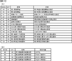
図3は、本実施例で用いられる演出制御コマンドの内容の一例を示す説明図である。演出制御コマンドは、例えば2バイト構成であり、1バイト目はMODE(コマンドの分類)を示し、2バイト目はEXT(コマンドの種類)を表す。尚、図3に示されたコマンド形態は一例であって、他のコマンド形態を用いてもよい。ここで、XXHは不特定の16進数であることを示し、演出制御コマンドによる指示内容に応じた値であればよい。   FIG. 3 is an explanatory diagram illustrating an example of the contents of the effect control command used in the present embodiment. The effect control command has, for example, a 2-byte configuration. The first byte indicates MODE (classification of command), and the second byte indicates EXT (type of command). Note that the command form shown in FIG. 3 is an example, and another command form may be used. Here, XXH indicates an unspecified hexadecimal number, and may be any value as long as it is in accordance with the instruction content of the effect control command.

コマンド8001Hは、第1特別図柄表示器4Aでの変動開始を指定する第1変動開始コマンドである。コマンド8002Hは、第2特別図柄表示器4Bでの変動開始を指定する第2変動開始コマンドである。コマンド81XXHは、変動パターン(変動時間)を指定する変動パターン指定コマンドであり、指定する変動パターンなどに応じて、異なるEXTデータが設定される。   The command 8001H is a first variation start command for designating a variation start on the first special symbol display 4A. The command 8002H is a second variation start command for designating the start of variation on the second special symbol display 4B. The command 81XXH is a variation pattern designation command for designating a variation pattern (variation time), and different EXT data is set according to the variation pattern to be designated.

コマンド8CXXHは、変動表示結果通知コマンドであり、変動表示結果を指定する演出制御コマンドである。尚、コマンド8C00Hは、「はずれ」となる旨の事前決定結果を示すコマンドである。コマンド8C01Hは、「大当り」で大当り種別が「確変大当りA」となる旨を通知するコマンドである。コマンド8C02Hは、「大当り」で大当り種別が「確変大当りB」となる旨を通知するコマンドである。コマンド8C03Hは、「大当り」で大当り種別が「非確変大当り」となる旨を通知するコマンドである。   The command 8CXXH is a variable display result notification command, and is an effect control command for specifying the variable display result. It should be noted that the command 8C00H is a command indicating a pre-determined result indicating "outside". The command 8C01H is a command for notifying that the big hit is “big hit big A” in “big hit”. The command 8C02H is a command for notifying that the big hit is “big hit big B” in “big hit”. The command 8C03H is a command for notifying that the "big hit" and the big hit type is "non-probable variable big hit".

コマンド8F00Hは、演出図柄の変動停止(確定)を指定する図柄確定コマンドである。コマンド95XXHは、その時点の遊技状態を指定する遊技状態指定コマンドである。   The command 8F00H is a symbol confirmation command for designating the stop (decision) of the effect symbol. The command 95XXH is a game state designation command for designating the current game state.

コマンドA0XXHは、大当り遊技状態の開始を指定する大当り開始指定コマンド(「ファンファーレコマンド」ともいう)である。コマンドA1XXHは、大当り遊技状態にて、大入賞口が開放状態となったこと及び大入賞口が開放状態である期間であることを通知する大入賞口開放中通知コマンドである。コマンドA2XXHは、大当り遊技状態にて、大入賞口が開放状態から閉鎖状態となったこと及び大入賞口が閉鎖状態である期間であることを通知する大入賞口開放後通知コマンドである。コマンドA3XXHは、大当り遊技状態の終了を指定する大当り終了指定コマンドである。   The command A0XXH is a jackpot start designation command (also referred to as a “fan fare command”) for designating the start of the jackpot gaming state. The command A1XXH is a special winning opening opening notification command for notifying that the special winning opening is in the open state and that the special winning opening is in the open state in the big hit gaming state. The command A2XXH is a notification command after the opening of the special winning opening that notifies that the special winning opening has changed from the open state to the closed state in the big hit gaming state and that the special winning opening is in the closed state. The command A3XXH is a big hit end designation command for designating the end of the big hit gaming state.

尚、大入賞口開放中通知コマンドや大入賞口開放後通知コマンドでは、例えば通常開放大当り状態や短期開放大当り状態のラウンドの実行回数(例えば「1」〜「16」または「1」〜「5」)に対応したEXTデータが設定される。   Note that the notification command during opening of the special winning opening and the notification command after opening the special winning opening include, for example, the number of executions of the round in the state of the normal open jackpot or the short-term open jackpot (for example, “1” to “16” or “1” to “5” )) Is set.

コマンドB100Hは、普通入賞球装置6Aが形成する第1始動入賞口への入賞によって第1始動条件が成立したことを通知する第1始動口入賞指定コマンドである。コマンドB200Hは、普通可変入賞球装置6Bが形成する第2始動入賞口への入賞によって第2始動条件が成立したことを通知する第2始動口入賞指定コマンドである。   The command B100H is a first starting port winning designation command for notifying that the first starting condition has been established by winning the first starting winning port formed by the normal winning ball device 6A. The command B200H is a second starting port winning designation command for notifying that the second starting condition has been established by winning in the second starting winning port formed by the normally variable winning ball apparatus 6B.

コマンドC1XXHは、第1特図保留記憶数を通知する第1保留記憶数通知コマンドである。コマンドC2XXHは、第2特図保留記憶数を通知する第2保留記憶数通知コマンドである。   The command C1XXH is a first reserved storage number notification command for notifying the first special figure reserved storage number. The command C2XXH is a second reserved storage number notification command for notifying the second special figure reserved storage number.

主基板11に搭載された遊技制御用マイクロコンピュータ100は、例えば1チップのマイクロコンピュータであり、遊技制御用のプログラムや固定データ等を記憶するROM101(Read Only Memory 101)と、遊技制御用のワークエリアを提供するRAM102(Random Access Memory 102)と、遊技制御用のプログラムを実行して制御動作を行うCPU103(Central Processing Unit 103)と、CPU103とは独立して乱数値を示す数値データの更新を行う乱数回路104と、I/O105(Input/Outputport 105)とを備えて構成される。   The game control microcomputer 100 mounted on the main board 11 is, for example, a one-chip microcomputer, and includes a ROM 101 (Read Only Memory 101) that stores a game control program and fixed data, and a game control work. A RAM 102 (Random Access Memory 102) that provides an area, a CPU 103 (Central Processing Unit 103) that executes a game control program to perform a control operation, and updates numerical data indicating a random number value independently of the CPU 103. It is configured to include a random number circuit 104 for performing the processing and an I / O 105 (Input / Output port 105).

一例として、遊技制御用マイクロコンピュータ100では、CPU103がROM101から読み出したプログラムを実行することにより、遊技の進行を制御するための各種処理が実行される。   As an example, in the game control microcomputer 100, various processes for controlling the progress of the game are executed by the CPU 103 executing the program read from the ROM 101.

主基板11では、特図表示結果判定用の乱数値MR1、大当り種別判定用の乱数値MR2、変動パターン判定用の乱数値MR3、普図表示結果判定用の乱数値MR4等の各種乱数値の数値データが、カウント可能に制御される。尚、乱数回路104は、これらの乱数値MR1〜MR4の一部または全部を示す数値データをカウントできるものであればよく、乱数回路104にてカウントしない乱数値については、CPU103が、ソフトウェアによって各種の数値データを更新することでカウントするようにすればよい。   On the main board 11, various random number values such as a random number value MR1 for determining the special figure display result, a random number value MR2 for determining the big hit type, a random number value MR3 for determining the variation pattern, and a random number value MR4 for determining the normal figure display result are used. Numerical data is controlled to be countable. The random number circuit 104 only needs to be able to count the numerical data indicating a part or all of the random number values MR1 to MR4. It is sufficient to count by updating the numerical data of.

図5は、本実施例の変動パターンを示している。本実施例では、図5に示すような複数の変動パターンが予め用意されている。具体的に、本実施例では、変動表示結果が「はずれ」となる場合のうち、演出図柄の変動表示態様が「非リーチ」である場合と「リーチ」である場合のそれぞれに対応して、また、変動表示結果が「大当り」となる場合などに対応して、複数の変動パターンが予め用意されている。   FIG. 5 shows a fluctuation pattern of the present embodiment. In this embodiment, a plurality of fluctuation patterns as shown in FIG. 5 are prepared in advance. Specifically, in the present embodiment, among the cases where the fluctuation display result is “outside”, corresponding to the case where the fluctuation display mode of the effect symbol is “non-reach” and the case where “reach”, Also, a plurality of variation patterns are prepared in advance in response to a case where the variation display result is “big hit”.

変動表示結果が「大当り」である場合に対応した変動パターンである大当り変動パターンや、演出図柄の変動表示態様が「リーチ」である場合のリーチ変動パターンには、ノーマルリーチのリーチ演出が実行されるノーマルリーチ変動パターンと、スーパーリーチα、スーパーリーチβといったスーパーリーチのリーチ演出が実行されるスーパーリーチ変動パターンとがある。尚、本実施例では、ノーマルリーチ変動パターンを1種類のみしか設けていないが、本発明はこれに限定されるものではなく、スーパーリーチと同様に、ノーマルリーチα、ノーマルリーチβ、…のように、複数のノーマルリーチ変動パターンを設けても良い。また、スーパーリーチ変動パターンでも、スーパーリーチαやスーパーリーチβに加えてスーパーリーチγ…といった3以上のスーパーリーチ変動パターンを設けても良い。   The reach effect of the normal reach is executed on the big hit change pattern which is a change pattern corresponding to the case where the change display result is "big hit" or the reach change pattern when the change display mode of the effect symbol is "reach". There are a normal reach variation pattern and a super reach variation pattern in which a super reach reach effect such as super reach α and super reach β is executed. In this embodiment, only one type of normal reach variation pattern is provided, but the present invention is not limited to this, and a plurality of normal reach variation patterns such as normal reach α, normal reach β,. May be provided. Also, in the super reach variation pattern, three or more super reach variation patterns such as super reach γ, in addition to super reach α and super reach β, may be provided.

図5に示すように、本実施例におけるノーマルリーチのリーチ演出が実行されるノーマルリーチ変動パターンの特図変動時間については、スーパーリーチ変動パターンであるスーパーリーチα、スーパーリーチβよりも短く設定されている。また、本実施例におけるスーパーリーチα、スーパーリーチβといったスーパーリーチのリーチ演出が実行されるスーパーリーチ変動パターンの特図変動時間については、スーパーリーチβのスーパーリーチ演出が実行される変動パターンの方が、スーパーリーチαのスーパーリーチ演出が実行される変動パターンよりも特図変動時間が長く設定されている。   As shown in FIG. 5, the special figure variation time of the normal reach variation pattern in which the reach effect of the normal reach is executed in the present embodiment is set to be shorter than the super reach variation patterns super reach α and super reach β. . In the present embodiment, the special figure variation time of the super-reach variation pattern in which the super-reach effect such as super-reach α and super-reach β is executed is the same as the variation pattern in which the super-reach effect of super-reach β is executed. However, the special figure fluctuation time is set longer than the fluctuation pattern in which the super reach effect of the super reach α is executed.

尚、本実施例では、前述したようにスーパーリーチβ、スーパーリーチα、ノーマルリーチの順に変動表示結果が「大当り」となる大当り期待度(大当り信頼度)が高くなるように設定されているため、ノーマルリーチ変動パターン及びスーパーリーチ変動パターンにおいては変動時間が長いほど大当り期待度(大当り信頼度)が高くなっている。また、本実施例では、大当りとなる場合に、必ずリーチ状態となってスーパーリーチβ、スーパーリーチα、ノーマルリーチのいずれかが実行されるようになっているが、本発明はこれに限定されるものではなく、非リーチの変動パターンでも大当りとなる場合があるようにしてもよい。尚、詳細は後述するが、本実施例のスーパーリーチの変動パターンは、リーチ演出中において遊技者に対してプッシュボタン31Bの操作を促す操作促進画像及び操作促進メッセージを演出表示装置5に表示し、変動表示結果が大当りであれば、プッシュボタン31Bの操作に基づいて可動役物400を動作させて大当りの報知を行うようになっている。   In the present embodiment, as described above, since the fluctuation display result becomes “big hit” in the order of super reach β, super reach α, and normal reach, the big hit expectation (big hit reliability) is set to be high. In the normal reach variation pattern and the super reach variation pattern, as the variation time is longer, the big hit expectation (big hit reliability) is higher. Further, in the present embodiment, when a big hit occurs, a reach state is always established and any of the super reach β, the super reach α, and the normal reach is executed, but the present invention is not limited to this. Instead, a non-reach fluctuation pattern may be a big hit. Although the details will be described later, the variation pattern of the super reach of the present embodiment displays an operation promotion image and an operation promotion message that prompt the player to operate the push button 31B during the reach effect on the effect display device 5. If the result of the fluctuation display is a big hit, the movable hit 400 is operated based on the operation of the push button 31B to notify the big hit.

図2に示す遊技制御用マイクロコンピュータ100が備えるROM101には、ゲーム制御用のプログラムの他にも、遊技の進行を制御するために用いられる各種の選択用データ、テーブルデータなどが格納されている。例えば、ROM101には、CPU103が各種の判定や決定、設定を行うために予め用意された複数の判定テーブルや設定テーブルなどを構成するデータが記憶されている。また、ROM101には、CPU103が主基板11から各種の制御コマンドとなる制御信号を送信するために用いられる複数のコマンドテーブルを構成するテーブルデータや、図5に示すような変動パターンを複数種類格納する変動パターンテーブルを構成するテーブルデータなどが、記憶されている。   The ROM 101 of the game control microcomputer 100 shown in FIG. 2 stores various selection data, table data, and the like used for controlling the progress of the game, in addition to the game control program. . For example, the ROM 101 stores data constituting a plurality of determination tables and setting tables prepared in advance for the CPU 103 to perform various determinations, determinations, and settings. Further, the ROM 101 stores a plurality of command data used for the CPU 103 to transmit control signals serving as various control commands from the main board 11 and a plurality of types of variation patterns as shown in FIG. And the like, which stores the changing pattern table.

図6は、ROM101に記憶される表示結果判定テーブルの構成例を示している。本実施例では、表示結果判定テーブルとして、第1特図と第2特図とで共通の表示結果判定テーブルを用いているが、本発明はこれに限定されるものではなく、第1特図と第2特図とで個別の表示結果判定テーブルを用いるようにしても良い。   FIG. 6 shows a configuration example of the display result determination table stored in the ROM 101. In the present embodiment, a common display result determination table is used for the first special figure and the second special figure as the display result determination table. However, the present invention is not limited to this. A separate display result determination table may be used for the second special map and the second special map.

表示結果判定テーブルは、第1特別図柄表示器4Aや第2特別図柄表示器4Bの特図ゲームにおいて確定特別図柄が導出表示される前に、その変動表示結果を「大当り」として大当り遊技状態に制御するか否かを、乱数値MR1に基づいて決定するために参照されるテーブルである。   Before the final special symbol is derived and displayed in the special figure game of the first special symbol display 4A or the second special symbol display 4B, the display result determination table sets the fluctuation display result to "big hit" to enter the big hit gaming state. 9 is a table referred to for determining whether or not to control based on a random number value MR1.

本実施例の表示結果判定テーブルでは、遊技状態が通常状態または時短状態(低確状態)であるか、確変状態(高確状態)であるかに応じて、乱数値MR1と比較される数値(判定値)が、「大当り」や「はずれ」の特図表示結果に割り当てられている。   In the display result determination table according to the present embodiment, a numerical value (which is compared with the random number value MR1) depending on whether the game state is the normal state, the time saving state (low-probability state), or the probable change state (high-probability state). (Judgment value) is assigned to the special map display result such as “big hit” or “out”.

表示結果判定テーブルでは、特図表示結果を「大当り」として大当り遊技状態に制御するか否かの決定結果に対して判定用データが割り当てられている。具体的に、本実施例では、遊技状態が確変状態(高確状態)であるときに、通常状態または時短状態(低確状態)であるときよりも多くの判定値が、「大当り」の特図表示結果に割り当てられている。これにより、確変制御が行われる確変状態(高確状態)では、通常状態または時短状態(低確状態)であるときに特図表示結果を「大当り」として大当り遊技状態に制御すると決定される確率(本実施例では約1/300)に比べて、特図表示結果を「大当り」として大当り遊技状態に制御すると決定される確率が高くなる(本実施例では約1/30)。即ち、表示結果判定テーブルでは、遊技状態が確変状態(高確状態)であるときに、通常状態や時短状態であるときに比べて大当り遊技状態に制御すると決定される確率が高くなるように、判定用データが大当り遊技状態に制御するか否かの決定結果に割り当てられている。   In the display result determination table, determination data is assigned to the determination result of whether to control the special figure display result to the big hit game state with the big hit as the big hit. More specifically, in the present embodiment, when the gaming state is the probable state (high accuracy state), a larger number of determination values than in the normal state or the time saving state (low accuracy state) are "big hits". Assigned to the figure display result. Accordingly, in the probability change state (high accuracy state) in which the probability change control is performed, the probability that the special map display result is determined to be “big hit” and the game is controlled to the big hit game state in the normal state or the time saving state (low accuracy state). As compared with (approximately 1/300 in the present embodiment), the probability that it is determined that the special figure display result is set to “big hit” and the state is controlled to the big hit gaming state is increased (about 1/30 in the present embodiment). That is, in the display result determination table, when the gaming state is in the probable state (high accuracy state), the probability of being determined to be controlled to the big hit gaming state is higher than when the gaming state is in the normal state or the time saving state. The determination data is assigned to the result of determining whether or not to control the jackpot game state.

尚、ROM101には、大当り遊技状態に制御すると決定されたときに、乱数値MR2に基づき、大当り種別を複数種類のいずれかに決定するために参照される大当り種別判定テーブルや、乱数値MR3に基づいて変動パターンを、前述した図5に示す変動パターンのいずれかに決定するための変動パターン判定テーブルも記憶されている。   In the ROM 101, when it is determined that the game is controlled to the big hit game state, the big hit type determination table and the random number value MR3 which are referred to to determine the big hit type to any one of a plurality of types based on the random value MR2. A variation pattern determination table for determining the variation pattern based on the variation pattern shown in FIG. 5 is also stored.

図7は、ROM101に記憶される大当り種別判定テーブルの構成例を示している。本実施例の大当り種別判定テーブルは、特図表示結果を「大当り」として大当り遊技状態に制御すると決定されたときに、大当り種別判定用の乱数値MR2に基づき、大当り種別を複数種類のいずれかに決定するために参照されるテーブルである。大当り種別判定テーブルでは、特図ゲームにおいて変動表示(変動)が行われた特別図柄が第1特図(第1特別図柄表示器4Aによる特図ゲーム)であるか第2特図(第2特別図柄表示器4Bによる特図ゲーム)であるかに応じて、大当り種別判定用の乱数値MR2と比較される数値(判定値)が、「非確変」や「確変大当りA」、「確変大当りB」といった複数種類の大当り種別に割り当てられている。   FIG. 7 shows a configuration example of the big hit type determination table stored in the ROM 101. The jackpot type determination table of the present embodiment, when it is determined to control the special map display result to "big hit" to the big hit gaming state, based on the random number value MR2 for big hit type determination, one of a plurality of big hit types Is a table that is referred to in order to determine. In the big hit type determination table, the special symbol for which the fluctuation display (fluctuation) is performed in the special figure game is the first special figure (a special figure game using the first special symbol display 4A) or the second special figure (the second special figure). The numerical value (judgment value) to be compared with the random number value MR2 for the jackpot type determination is “non-probable change”, “probable change big hit A”, “probable change big hit B” "Are assigned to a plurality of types of jackpots.

ここで、本実施例における大当り種別について、図7(B)を用いて説明すると、本実施例では、大当り種別として、大当り遊技状態の終了後において高確制御と時短制御とが実行されて高確高ベース状態に移行する確変大当りAや確変大当りBと、大当り遊技状態の終了後において時短制御のみが実行されて低確高ベース状態に移行する非確変大当りとが設定されている。   Here, the big hit type in the present embodiment will be described with reference to FIG. 7B. In the present embodiment, the high accuracy control and the time saving control are executed as the big hit type after the end of the big hit gaming state. Probably variable big hits A and B that shift to the high-probability base state, and non-probably variable big hits that perform only the time-saving control after completion of the big-hit game state and shift to the low-probability base state are set.

「確変大当りA」による大当り遊技状態と「非確変大当り」による大当り遊技状態では、前述したように、特別可変入賞球装置7を遊技者にとって有利な第1状態に変化させるラウンドが16回(いわゆる16ラウンド)、繰返し実行される通常開放大当りである。一方、「確変大当りB」による大当り遊技状態では、前述したように、特別可変入賞球装置7を遊技者にとって有利な第1状態に変化させるラウンドが5回(いわゆる5ラウンド)、繰返し実行される短期開放大当りである。よって、「確変大当りA」を16ラウンド(16R)確変大当りと呼称し、「確変大当りB」を5ラウンド(5R)確変大当りと呼称する場合がある。   As described above, in the jackpot game state based on the “probable variable jackpot A” and the jackpot game state based on the “non-probable variable jackpot A”, 16 rounds of changing the special variable prize ball device 7 to the first state advantageous to the player are performed (so-called “round”). 16 rounds), a normal open jackpot repeatedly executed. On the other hand, in the big hit game state with the “probable change big hit B”, as described above, five rounds (so-called five rounds) for changing the special variable winning ball device 7 to the first state advantageous to the player are repeatedly executed. It is a short-term open jackpot. Therefore, there is a case where “probably variable big hit A” is referred to as 16 round (16R) probability big hit and “probably variable big hit B” is called 5 round (5R) certain variable big hit.

確変大当りAや確変大当りBの大当り遊技状態の終了後において実行される高確制御と時短制御は、該大当り遊技状態の終了後において再度大当りが発生するまで継続して実行される。よって、再度発生した大当りが確変大当りAや確変大当りBである場合には、大当り遊技状態の終了後に再度、高確制御と時短制御が実行されるので、大当り遊技状態が通常状態を介することなく連続的に発生する、いわゆる連荘状態となる。   The high-accuracy control and the time-saving control executed after the big-hit jackpot A or the big-hit jackpot B have ended are continuously executed until the big hit occurs again after the big-hit game state ends. Therefore, if the jackpot that has recurred is the jackpot jackpot A or the jackpot jackpot B, the high-accuracy control and the time-saving control are executed again after the jackpot gaming state ends, so that the jackpot gaming state does not go through the normal state. It is a so-called connected state that occurs continuously.

一方、「非確変大当り」による大当り遊技状態の終了後において実行される時短制御は、所定回数(本実施例では100回)の特図ゲームが実行されること、或いは該所定回数の特図ゲームが実行される前に大当り遊技状態となることにより終了する。   On the other hand, the time-saving control executed after the end of the jackpot game state by the “non-probable variable jackpot” is that the special figure game is executed a predetermined number of times (100 times in this embodiment) or the special figure game of the predetermined number of times is executed. The game ends when the big hit game state is reached before is executed.

図7(A)に示す大当り種別判定テーブルの設定例では、変動特図が第1特図であるか第2特図であるかに応じて、「確変大当りA」と「確変大当りB」の大当り種別に対する判定値の割当てが異なっている。即ち、変動特図が第1特図である場合には、所定範囲の判定値(「81」〜「100」の範囲の値)がラウンド数の少ない「確変大当りB」の大当り種別に割り当てられる一方で、変動特図が第2特図である場合には、「確変大当りB」の大当り種別に対して判定値が割り当てられていない。このような設定により、第1特別図柄表示器4Aによる第1特図を用いた特図ゲームを開始するための第1開始条件が成立したことに基づいて大当り種別を複数種類のいずれかに決定する場合と、第2特別図柄表示器4Bによる第2特図を用いた特図ゲームを開始するための第2開始条件が成立したことに基づいて大当り種別を複数種類のいずれかに決定する場合とで、大当り種別をラウンド数の少ない「確変大当りB」に決定する割合を、異ならせることができる。特に、第2特図を用いた特図ゲームでは大当り種別を「確変大当りB」としてラウンド数の少ない短期開放大当り状態に制御すると決定されることがないので、例えば時短制御に伴う高開放制御により、普通可変入賞球装置6Bが形成する第2始動入賞口に遊技球が進入しやすい遊技状態において、得られる賞球が少ない短期開放大当り状態の頻発を回避して遊技興趣が低下してしまうことを防止できるようになっている。   In the setting example of the big hit type determination table shown in FIG. 7A, “probably big hit A” and “probably big hit B” are set according to whether the variation special figure is the first special figure or the second special figure. The assignment of the judgment value to the big hit type is different. That is, when the fluctuation special map is the first special map, a determination value in a predetermined range (a value in a range of “81” to “100”) is assigned to the big hit type of “probable big hit B” with a small number of rounds. On the other hand, when the fluctuation special map is the second special map, the determination value is not assigned to the big hit type of “probable change big hit B”. With such a setting, the jackpot type is determined to be one of a plurality of types based on the fact that the first start condition for starting the special figure game using the first special figure by the first special symbol display 4A is satisfied. And a case where the jackpot type is determined to be one of a plurality of types based on the satisfaction of a second start condition for starting a special figure game using the second special figure by the second special symbol display 4B. Thus, the rate at which the jackpot type is determined to be “probable jackpot B” with a small number of rounds can be made different. In particular, in the special map game using the second special map, it is not determined that the big hit type is “probably variable big hit B” and the state is controlled to the short open big hit state with a small number of rounds. In a game state in which game balls are likely to enter the second starting winning opening formed by the normally variable winning ball device 6B, avoiding frequent occurrence of short-term open jackpots in which few prize balls are obtained reduces game interest. Can be prevented.

尚、図7(A)に示す大当り種別判定テーブルの設定例では、「非確変」の大当り種別に対する判定値の割当ては、変動特図が第1特図であるか第2特図であるかに係わらず同一とされているので、非確変の大当りとなる確率と確変の大当りとなる確率は、変動特図が第1特図であるか第2特図であるかにかかわらず同一とされている。   In the setting example of the jackpot type determination table shown in FIG. 7A, the assignment of the determination value to the “non-probable change” jackpot type is based on whether the fluctuation special figure is the first special figure or the second special figure. Therefore, the probability of a non-probable variable jackpot and the probability of a probable variable jackpot are the same regardless of whether the fluctuation special map is the first special map or the second special map. ing.

よって、上記したように、「確変大当りB」に対する判定値の割り当てが、変動特図が第1特図であるか第2特図であるかに応じて異なることに応じて、「確変大当りA」に対する判定値の割り当ても変動特図が第1特図であるか第2特図であるかに応じて異なり、ラウンド数の多い「確変大当りA」については、変動特図が第2特図である場合の方が第1特図である場合よりも決定され易くなるように設定されている。   Therefore, as described above, depending on whether the assignment of the determination value to “probably variable big hit B” is different depending on whether the variation special figure is the first special figure or the second special figure, the “probable variable big hit A” Is also different depending on whether the fluctuation special figure is the first special figure or the second special figure, and for "probable variable big hit A" having a large number of rounds, the fluctuation special figure is the second special figure. Is set to be more easily determined in the case of.

尚、変動特図が第2特図である場合にも、変動特図が第1特図である場合とは異なる所定範囲の判定値が、「確変大当りB」の大当り種別に割り当てられるようにしてもよい。例えば、変動特図が第2特図である場合には、変動特図が第1特図である場合に比べて少ない判定値が、「確変大当りB」の大当り種別に割り当てられてもよい。あるいは、変動特図が第1特図であるか第2特図であるかにかかわらず、共通のテーブルデータを参照して、大当り種別の決定を行うようにしてもよい。   It should be noted that, even when the fluctuation special map is the second special map, a judgment value in a predetermined range different from the case where the fluctuation special map is the first special map is assigned to the big hit type of “probable variable big hit B”. You may. For example, when the fluctuation special map is the second special map, a smaller determination value than when the fluctuation special map is the first special map may be assigned to the big hit type of “probable variable big hit B”. Alternatively, the big hit type may be determined with reference to the common table data regardless of whether the fluctuation special map is the first special map or the second special map.

また、ROM101に記憶されている変動パターン判定テーブルとしては、「大当り」とすることが事前決定されたときに使用される大当り用変動パターン判定テーブルと、「はずれ」にすることが事前決定されたときに使用されるはずれ用変動パターン判定テーブルとが予め用意されている。尚、本実施例では、はずれのときよりも大当りとなるときの方がリーチの変動パターンが決定されやすくなり、リーチが発生した場合の方が大当りになる可能性(信頼度や期待度)が高くなるとともに、同じリーチの変動パターンであっても、ノーマルリーチよりもスーパーリーチの方が大当りになる可能性(信頼度や期待度)が高く、同じスーパーリーチであってもスーパーリーチβの変動パターンの方が、確変大当りになる可能性(信頼度や期待度)が高くなるように、大当り用変動パターン判定テーブルとはずれ用変動パターン判定テーブルにおいて、各変動パターンに対応する判定値が設定されている。   The variation pattern determination table stored in the ROM 101 includes a jackpot variation pattern determination table used when “big hit” is determined in advance, and “out” as the variation pattern determination table. An out-of-office variation pattern determination table that is sometimes used is prepared in advance. In the present embodiment, the fluctuation pattern of the reach is more easily determined when the hit is a big hit than when the hit is a loss, and the possibility (reliability and expectation) of the hit when the reach is generated is larger. The higher the reach, the higher the reach (reliability and expectation) of the super reach than the normal reach, even if the fluctuation pattern of the same reach, the fluctuation pattern of the super reach β even with the same super reach The determination values corresponding to the respective variation patterns are set in the variation pattern determination table for the big hit and the variation pattern determination table for the deviation so that the probability of the probability variation big hit (reliability and expectation) becomes higher. I have.

尚、はずれ用変動パターン判定テーブルは、合計保留記憶数や時短状態に対応した複数のテーブルを含んでおり、保留記憶数や時短状態に応じて、合計保留記憶数が2〜4個に対応する短縮の非リーチはずれの変動パターン(PA1−2)や、合計保留記憶数が5〜8個に対応する短縮の非リーチはずれの変動パターン(PA1−3)や、短縮の非リーチはずれの変動パターン(PA1−4)を、合計保留記憶数や遊技状態(時短状態)に応じて決定することで、合計保留記憶数が多くなる程、短い変動パターンが実行され易い、つまり、単位時間当りの変動回数が高まることで、無駄な始動入賞の発生を防ぐことが可能であるとともに、時短制御中(時短状態中)では、時短制御が実行されていないときよりも、短縮の非リーチはずれの変動パターン(PA1−4)が多く決定されて単位時間当りの変動回数が高まることで、次の大当りまでの期間を短縮でき、遊技者の連荘感を向上できるようになっている。   Note that the outlier variation pattern determination table includes a plurality of tables corresponding to the total number of pending storages and the time saving state, and the total number of pending storages corresponds to 2 to 4 according to the number of pending storages and the time saving state. Short non-reach loss variation pattern (PA1-2), shortened non-reach loss variation pattern (PA1-3) corresponding to a total of 5-8 stored data, and shortened non-reach loss variation pattern By determining (PA1-4) in accordance with the total number of suspended storages and the game state (time saving state), a shorter fluctuation pattern is more easily executed as the total number of suspended storages increases, that is, fluctuations per unit time. By increasing the number of times, it is possible to prevent the occurrence of useless starting winnings, and the change in the non-reach of the shortened non-reach during the time reduction control (during the time reduction state) is smaller than when the time reduction control is not executed. Pattern (PA1-4) that is often determined by increasing the number of times of the change per unit time, it can reduce the time to the next jackpot, and to be able to improve the extended game player's sense of.

図2に示す遊技制御用マイクロコンピュータ100が備えるRAM102は、その一部または全部が所定の電源基板からのバックアップ電源によってバックアップされているバックアップRAMであればよい。すなわち、パチンコ遊技機1に対する電力供給が停止しても、所定期間(バックアップ電源としてのコンデンサが放電してバックアップ電源が電力供給不能になるまで)は、RAM102の一部または全部の内容は保存され、再度の電源投入にて、遊技状態すなわち遊技制御手段の制御状態に応じたデータ(特図プロセスフラグなど)と未払出賞球数を示すデータ等の遊技の進行状態を示すデータを引き継ぐようにすればよい。   The RAM 102 included in the game control microcomputer 100 shown in FIG. 2 may be a backup RAM partially or entirely backed up by a backup power supply from a predetermined power supply board. That is, even if the power supply to the pachinko gaming machine 1 is stopped, a part or all of the content of the RAM 102 is retained for a predetermined period (until the capacitor serving as the backup power supply is discharged and the backup power supply becomes unable to supply power). When the power is turned on again, the data indicating the progress state of the game, such as the data corresponding to the game state, that is, the control state of the game control means (such as a special process flag) and the data indicating the number of unpaid balls, is taken over. do it.

このようなRAM102には、遊技の進行などを制御するために用いられる各種のデータを保持する領域として、図示しない遊技制御用データ保持エリアが設けられている。遊技制御用データ保持エリアは、普通入賞球装置6Aが形成する第1始動入賞口を遊技球が通過(進入)して始動入賞(第1始動入賞)が発生したものの未だ開始されていない第1特図を用いた特図ゲームの保留データとして、乱数値MR1、乱数値MR2、乱数値MR3を示す数値データなどを記憶する第1特図保留記憶部と、普通可変入賞球装置6Bが形成する第2始動入賞口を遊技球が通過(進入)して始動入賞(第2始動入賞)が発生したものの未だ開始されていない第2特図を用いた特図ゲームの保留データとして、乱数値MR1、乱数値MR2、乱数値MR3を示す数値データなどを記憶する第2特図保留記憶部と、普図保留記憶部と、特図プロセスフラグ等の遊技の進行状況などに応じて状態を更新可能な複数種類のフラグが設けられている遊技制御フラグ設定部と、遊技の進行を制御するために用いられる各種のタイマが設けられている遊技制御タイマ設定部と、遊技の進行を制御するために用いられるカウント値を計数するための複数種類のカウンタが設けられている遊技制御カウンタ設定部と、遊技の進行を制御するために用いられるデータを一時的に記憶する各種のバッファが設けられている遊技制御バッファ設定部と、を備えている。   The RAM 102 is provided with a game control data holding area (not shown) as an area for holding various data used for controlling the progress of the game and the like. The game control data holding area includes a first winning prize (first starting prize) generated by a game ball passing (entering) a first starting prize opening formed by the normal winning prize ball device 6A, but the first not-yet-started first prize is not yet started. A first special figure holding storage unit for storing numerical data indicating the random number value MR1, the random number value MR2, the random number value MR3, and the like as the holding data of the special figure game using the special figure, and the normal variable winning prize ball device 6B are formed. A random number value MR1 is used as pending data of a special figure game using a second special figure that has not started yet, although a game ball has passed (entered) the second starting winning opening and a start winning (second start winning) has occurred. , The second special figure holding storage unit for storing numerical data indicating the random number value MR2 and the random number value MR3, the general figure holding storage unit, and the state can be updated according to the progress of the game such as the special figure process flag. Multiple types of flags A game control flag setting unit, a game control timer setting unit provided with various timers used to control the progress of the game, and a count value used to control the progress of the game. A game control counter setting unit provided with a plurality of types of counters for performing the game, and a game control buffer setting unit provided with various buffers for temporarily storing data used for controlling the progress of the game. , Is provided.

図2に示すように、演出制御基板12には、プログラムに従って制御動作を行う演出制御用CPU120と、演出制御用のプログラムや固定データ等を記憶するROM121と、演出制御用CPU120のワークエリアを提供するRAM122と、演出表示装置5での表示動作の制御内容を決定するための処理などを実行する表示制御部123と、演出制御用CPU120とは独立して乱数値を示す数値データの更新を行う乱数回路124と、I/O125とが搭載されている。   As shown in FIG. 2, the effect control board 12 provides an effect control CPU 120 that performs a control operation according to a program, a ROM 121 that stores an effect control program, fixed data, and the like, and a work area of the effect control CPU 120. RAM 122, a display control unit 123 that executes processing for determining the control content of the display operation in the effect display device 5, and the effect control CPU 120, and independently updates numerical data indicating a random number. A random number circuit 124 and an I / O 125 are mounted.

一例として、演出制御基板12では、演出制御用CPU120がROM121から読み出した演出制御用のプログラムを実行することにより、演出用の電気部品による演出動作を制御するための各種処理が実行される。例えば、これら演出動作を制御するための処理として、演出制御用CPU120がI/O125を介して演出制御基板12の外部から各種信号の入力を受け付ける受信処理、演出制御用CPU120がI/O125を介して演出制御基板12の外部へと各種信号を出力する送信処理なども行われる。   As an example, in the effect control board 12, the effect control CPU 120 executes an effect control program read from the ROM 121 to execute various processes for controlling the effect operation by the electric components for effect. For example, as processing for controlling these rendering operations, the rendering control CPU 120 receives input of various signals from outside the rendering control board 12 via the I / O 125, and the rendering control CPU 120 transmits the I / O 125 via the I / O 125. A transmission process for outputting various signals to the outside of the effect control board 12 is also performed.

尚、演出制御基板12の側でも、主基板11と同様に、例えば、各種演出の実行、非実行や、演出の種別等を決定するための各種の乱数値(演出用乱数ともいう)が設定されている。また、ROM121には、演出制御用のプログラムの他にも、可動役物400の演出動作を制御するために用いられる各種のテーブルデータ、例えば、各種演出の実行、非実行や、演出の種別等を決定するための複数の判定テーブルを構成するテーブルデータ、各変動パターンに対応する演出制御パターンを構成するパターンデータなどが記憶されている。   In the same manner as the main board 11, on the side of the effect control board 12, for example, various random numbers (also referred to as effect random numbers) for determining the execution and non-execution of various effects and the type of effect are set. Have been. In addition, in the ROM 121, in addition to the program for effect control, various table data used for controlling the effect operation of the movable accessory 400, for example, execution and non-execution of various effects, types of effects, etc. Are stored, table data constituting a plurality of determination tables for determining the pattern, pattern data constituting an effect control pattern corresponding to each variation pattern, and the like.

演出制御パターンのうち、特図変動時演出制御パターンは、各変動パターンに対応して、特別図柄の変動が開始されてから確定特別図柄が導出表示されるまでの期間における、演出図柄の変動表示動作や可動役物400を動作させるリーチ演出等の様々な演出動作の制御内容を示すデータなどから構成されている。   Of the effect control patterns, the effect control pattern at the time of the special figure change, the change display of the effect symbol during the period from the start of the change of the special symbol to the display of the fixed special symbol corresponding to each change pattern. It is composed of data and the like indicating the control contents of various effecting operations such as an operation and a reach effect for operating the movable role 400.

また、RAM122には、演出動作を制御するために用いられる各種データを保持する領域として、例えば図示しない演出制御用データ保持エリアが設けられている。演出制御用データ保持エリアは、演出動作状態や主基板11から送信された演出制御コマンド等に応じて状態を更新可能な複数種類のフラグが設けられている演出制御フラグ設定部と、各種演出動作の進行を制御するために用いられる複数種類のタイマやカウンタが設けられている演出制御タイマ設定部や演出制御カウンタ設定部と、各種演出動作の進行を制御するために用いられるデータを一時的に記憶する各種のバッファが設けられている演出制御バッファ設定部とを備えている。   The RAM 122 is provided with, for example, an effect control data holding area (not shown) as an area for holding various data used for controlling the effect operation. The effect control data holding area includes an effect control flag setting unit provided with a plurality of types of flags capable of updating a state in accordance with an effect operation state and an effect control command transmitted from the main board 11, and various effect operations. The effect control timer setting unit and the effect control counter setting unit, which are provided with a plurality of types of timers and counters used to control the progress of the process, temporarily store the data used to control the progress of various effect operations. An effect control buffer setting unit in which various buffers for storing are provided.

尚、本実施例では、演出制御バッファ設定部の所定領域に、第1特図保留記憶の合計保留記憶数の最大値(例えば「4」)に対応した格納領域(バッファ番号「1−1」〜「1−4」に対応した領域)と、第2特図保留記憶の合計保留記憶数の最大値(例えば「4」)に対応した格納領域(バッファ番号「2−1」〜「2−4」に対応した領域)が設けられ、その時点の保留記憶の状況を特定可能な保留記憶バッファを構成するデータが記憶されており、該保留記憶バッファのデータに基づいて、第1保留記憶表示エリア5Dと第2保留記憶表示エリア5Uの保留表示が表示される。   In the present embodiment, a storage area (buffer number “1-1”) corresponding to the maximum value (for example, “4”) of the total number of the reserved first special figure storages is stored in a predetermined area of the effect control buffer setting unit. To "1-4" and the storage areas (buffer numbers "2-1" to "2-") corresponding to the maximum value (for example, "4") of the total reserved storage number of the second special figure reserved storage. 4) is provided, and data constituting a pending storage buffer capable of specifying the status of the pending storage at that time is stored, and the first pending storage display is performed based on the data in the pending storage buffer. A hold display of the area 5D and the second hold storage display area 5U is displayed.

また、図2に示すように、演出制御基板12には、可動役物400を垂直方向に駆動するための可動役物第1駆動モータ301と、可動役物400を構成する第1駆動部及び第2駆動部(図1参照)を水平方向に駆動するための可動役物第2駆動モータ302と、プッシュボタン31Bを非突出状態から突出状態に変化させるためのボタン駆動モータ303と、が接続されている。演出制御用CPU120は、これら可動役物第1駆動モータ301、可動役物第2駆動モータ302、ボタン駆動モータ303を個別に制御することで、可動役物400とプッシュボタン31Bとを個別に制御することが可能となっている。   Further, as shown in FIG. 2, on the effect control board 12, a movable accessory first drive motor 301 for driving the movable accessory 400 in the vertical direction, a first driving unit constituting the movable accessory 400, and A movable accessory second drive motor 302 for driving the second drive unit (see FIG. 1) in the horizontal direction is connected to a button drive motor 303 for changing the push button 31B from the non-projected state to the projected state. Have been. The effect control CPU 120 individually controls the movable auditors 400 and the push button 31B by individually controlling the movable auditors first drive motor 301, the movable auditors second drive motor 302, and the button drive motor 303. It is possible to do.

次に、本実施例のパチンコ遊技機1の動作(作用)を説明する。主基板11では、所定の電源基板からの電力供給が開始されると、遊技制御用マイクロコンピュータ100が起動し、CPU103によって遊技制御メイン処理となる所定の処理が実行される。遊技制御メイン処理を開始すると、CPU103は、割込み禁止に設定した後、必要な初期設定を行う。この初期設定では、例えばRAM102がクリアされる。また、遊技制御用マイクロコンピュータ100に内蔵されたCTC(カウンタ/タイマ回路)のレジスタ設定を行う。これにより、以後、所定時間(例えば、2ミリ秒)ごとにCTCから割込み要求信号がCPU103へ送出され、CPU103は定期的にタイマ割込み処理を実行することができる。初期設定が終了すると、割込みを許可した後、ループ処理に入る。尚、遊技制御メイン処理では、パチンコ遊技機1の内部状態を前回の電力供給停止時の状態に復帰させるための処理を実行してから、ループ処理に入るようにしてもよい。   Next, an operation (operation) of the pachinko gaming machine 1 of the present embodiment will be described. In the main board 11, when the power supply from a predetermined power supply board is started, the game control microcomputer 100 is started, and the CPU 103 executes a predetermined process as a game control main process. When the game control main process is started, the CPU 103 sets necessary interrupt settings after setting interrupt prohibition. In this initial setting, for example, the RAM 102 is cleared. Further, a register of a CTC (counter / timer circuit) built in the game control microcomputer 100 is set. As a result, an interrupt request signal is sent from the CTC to the CPU 103 every predetermined time (for example, every 2 milliseconds), and the CPU 103 can periodically execute the timer interrupt process. When the initial setting is completed, an interrupt is permitted, and a loop process is started. In the game control main process, a process for returning the internal state of the pachinko gaming machine 1 to the state at the time of the previous power supply stop may be performed, and then the loop process may be started.

こうした遊技制御メイン処理を実行したCPU103は、CTCからの割込み要求信号を受信して割込み要求を受け付けると、図8のフローチャートに示す遊技制御用タイマ割込み処理を実行する。図8に示す遊技制御用タイマ割込み処理を開始すると、CPU103は、まず、所定のスイッチ処理を実行することにより、スイッチ回路110を介してゲートスイッチ21、第1始動口スイッチ22A、第2始動口スイッチ22B、カウントスイッチ23といった各種スイッチから入力される検出信号の状態を判定する(S11)。続いて、所定のメイン側エラー処理を実行することにより、パチンコ遊技機1の異常診断を行い、その診断結果に応じて必要ならば警告を発生可能とする(S12)。この後、所定の情報出力処理を実行する(S13)。   When receiving the interrupt request signal from the CTC and receiving the interrupt request, the CPU 103 that has executed the game control main process executes the game control timer interrupt process shown in the flowchart of FIG. When the game control timer interrupt process shown in FIG. 8 is started, the CPU 103 first executes a predetermined switch process, so that the gate switch 21, the first starting port switch 22A, the second starting port via the switch circuit 110. The state of the detection signal input from various switches such as the switch 22B and the count switch 23 is determined (S11). Subsequently, by executing predetermined main-side error processing, abnormality diagnosis of the pachinko gaming machine 1 is performed, and a warning can be generated if necessary according to the diagnosis result (S12). Thereafter, a predetermined information output process is executed (S13).

次に、乱数値MR1〜MR4といった遊技用乱数の少なくとも一部をソフトウェアにより更新するための遊技用乱数更新処理を実行する(S14)。この後、図9に示す特別図柄プロセス処理を実行する(S15)。   Next, a game random number update process for updating at least a part of the game random numbers such as the random number values MR1 to MR4 by software is executed (S14). Thereafter, the special symbol process shown in FIG. 9 is executed (S15).

特別図柄プロセス処理に続いて、普通図柄表示器20での表示動作(例えばセグメントLEDの点灯、消灯など)を制御して、普通図柄の変動表示や普通可変入賞球装置6Bの可動翼片の傾動動作設定などを行う普通図柄プロセス処理が実行される(S16)。その後、コマンド制御処理を実行することにより、主基板11から演出制御基板12などのサブ側の制御基板に対して制御コマンドを送信(出力)する(S17)。   Subsequent to the special symbol processing, the display operation (for example, turning on and off the segment LED) of the ordinary symbol display 20 is controlled to display the variation of the ordinary symbol and the tilting of the movable wing piece of the ordinary variable winning ball device 6B. Ordinary symbol process processing for performing operation setting and the like is executed (S16). Thereafter, by executing a command control process, a control command is transmitted (output) from the main board 11 to a control board on the sub side such as the effect control board 12 (S17).

図9は、特別図柄プロセス処理の一例を示すフローチャートである。この特別図柄プロセス処理では、まず、始動入賞判定処理を実行する(S21)。その後、遊技制御フラグ設定部152に設けられた特図プロセスフラグの値に応じて、S22〜S29の処理のいずれかを選択して実行する。   FIG. 9 is a flowchart illustrating an example of the special symbol process process. In the special symbol process process, first, a start winning determination process is executed (S21). After that, one of the processes of S22 to S29 is selected and executed according to the value of the special figure process flag provided in the game control flag setting section 152.

S21の始動入賞処理では、第1始動口スイッチ22Aや第2始動口スイッチ22Bによる第1始動入賞や第2始動入賞があったか否かを判定し、入賞があった場合には、乱数値MR1、MR2、MR3を抽出して、第1始動入賞である場合には、第1特図保留記憶部の空きエントリの最上位に格納し、第2始動入賞である場合には、第2特図保留記憶部の空きエントリの最上位に格納する。   In the start winning process of S21, it is determined whether or not there is a first start win or a second start win by the first start port switch 22A or the second start port switch 22B. MR2 and MR3 are extracted and stored at the top of the empty entry in the first special figure holding storage unit when the first special winning is set, and the second special figure holding is set when the second special winning is set. It is stored at the top of empty entries in the storage unit.

S22の特別図柄通常処理は、特図プロセスフラグの値が“0”のときに実行される。特別図柄通常処理では、保留データの有無などに基づいて特図ゲームを開始するか否かの判定が行われる。また、乱数値MR1を示す数値データに基づき、変動表示結果を「大当り」とするか否かを、その変動表示結果が導出表示される前に決定(事前決定)する。さらに、変動表示結果に対応して確定特別図柄(大当り図柄やはずれ図柄のいずれか)が設定される。そして、特図プロセスフラグの値が“1”に更新される。   The special symbol normal processing of S22 is executed when the value of the special figure process flag is “0”. In the special symbol normal processing, it is determined whether or not to start the special figure game based on the presence or absence of the hold data. Further, based on the numerical data indicating the random number value MR1, it is determined (predetermined) whether or not to make the variable display result a “big hit” before the variable display result is derived and displayed. Further, a fixed special symbol (either a big hit symbol or a missing symbol) is set in accordance with the fluctuation display result. Then, the value of the special figure process flag is updated to “1”.

S23の変動パターン設定処理は、特図プロセスフラグの値が“1”のときに実行される。変動パターン設定処理には、変動表示結果を「大当り」とするか否かの事前決定結果などに基づき、乱数値MR3を示す数値データを用いて変動パターンを複数種類のいずれかに決定する処理などが含まれている。そして、特図プロセスフラグの値が“2”に更新される。   The variation pattern setting process of S23 is executed when the value of the special figure process flag is “1”. In the variation pattern setting process, a process of determining a variation pattern to one of a plurality of types using numerical data indicating the random number value MR3 based on a result of a prior determination as to whether or not the variation display result is a "big hit" or the like. It is included. Then, the value of the special figure process flag is updated to “2”.

S24の特別図柄変動処理は、特図プロセスフラグの値が“2”のときに実行される。特別図柄変動処理には、第1特別図柄表示器4Aや第2特別図柄表示器4Bにて特別図柄を変動させるための設定を行う処理や、その特別図柄が変動を開始してからの経過時間を計測する処理などが含まれている。尚、特別図柄の変動経過時間が特図変動時間に達したときには、特図プロセスフラグの値が“3”に更新される。   The special symbol change process of S24 is executed when the value of the special figure process flag is “2”. The special symbol change process includes a process for setting a special symbol to be changed on the first special symbol display 4A and the second special symbol display 4B, and an elapsed time from the start of the change of the special symbol. And the like. When the change elapsed time of the special symbol reaches the special figure change time, the value of the special figure process flag is updated to “3”.

S25の特別図柄停止処理は、特図プロセスフラグの値が“3”のときに実行される。特別図柄停止処理には、第1特別図柄表示器4Aや第2特別図柄表示器4Bにて特別図柄の変動表示結果となる確定特別図柄を停止表示(導出)させるための設定を行う処理が含まれている。そして、大当りフラグがオンとなっているか否かの判定などが行われ、大当りフラグがオンである場合には特図プロセスフラグの値が“4”に更新される。その一方で、大当りフラグがオフである場合には、特図プロセスフラグの値が“0”に更新される。   The special symbol stop processing of S25 is executed when the value of the special figure process flag is “3”. The special symbol stop process includes a process of performing setting for stopping and displaying (deriving) a fixed special symbol which is a result of a variable display of the special symbol on the first special symbol display 4A or the second special symbol display 4B. Have been. Then, it is determined whether or not the big hit flag is on. If the big hit flag is on, the value of the special figure process flag is updated to "4". On the other hand, when the big hit flag is off, the value of the special figure process flag is updated to “0”.

S26の大当り開放前処理は、特図プロセスフラグの値が“4”のときに実行される。大当り開放前処理には、変動表示結果が「大当り」となったことなどに基づき、大当り遊技状態にてラウンドの実行を開始して大入賞口を開放状態とするための設定を行う処理などが含まれている。具体的には、大入賞口を開放状態とする期間の上限を「29秒」に設定するとともに、ラウンドを実行する上限回数となる大入賞口の開放回数を、「非確変大当り」または「確変大当りA」である場合には、「16回」に設定する。一方、大当り種別が「確変大当りB」である場合には、ラウンドを実行する上限回数となる大入賞口の開放回数を「5回」に設定する。このときには、特図プロセスフラグの値が“5”に更新される。   The big hit opening pre-processing of S26 is executed when the value of the special figure process flag is “4”. The big hit opening pre-processing includes, for example, a process of starting a round in the big hit gaming state and setting a big winning opening to an open state based on the fact that the fluctuation display result is "big hit". include. Specifically, the upper limit of the period during which the special winning opening is opened is set to “29 seconds”, and the number of times of opening the special winning opening, which is the upper limit of the number of times the round is executed, is set to “non-probable variable big hit” or “ If it is "Big hit A", it is set to "16 times". On the other hand, when the big hit type is “probable big hit B”, the number of times of opening the big winning port, which is the upper limit number of times of executing the round, is set to “5 times”. At this time, the value of the special figure process flag is updated to “5”.

S27の大当り開放中処理は、特図プロセスフラグの値が“5”のときに実行される。この大当り開放中処理には、大入賞口を開放状態としてからの経過時間を計測する処理や、その計測した経過時間やカウントスイッチ23によって検出された遊技球の個数などに基づいて、大入賞口を開放状態から閉鎖状態に戻すタイミングとなったか否かを判定する処理などが含まれている。そして、大入賞口を閉鎖状態に戻すときには、大入賞口扉用のソレノイド82に対するソレノイド駆動信号の供給を停止させる処理などを実行した後、特図プロセスフラグの値が“6”に更新される。   The big hit opening processing in S27 is executed when the value of the special figure process flag is “5”. The processing during the opening of the jackpot is based on the processing of measuring the elapsed time from the opening of the jackpot, and the number of game balls detected by the count switch 23 based on the measured elapsed time and the number of game balls detected by the count switch 23. For determining whether or not it is time to return from the open state to the closed state. When returning the special winning opening to the closed state, the process of stopping the supply of the solenoid drive signal to the solenoid 82 for the special winning opening door is executed, and then the value of the special drawing process flag is updated to “6”. .

S28の大当り開放後処理は、特図プロセスフラグの値が“6”のときに実行される。この大当り開放後処理には、大入賞口を開放状態とするラウンドの実行回数が大入賞口開放回数最大値に達したか否かを判定する処理や、大入賞口開放回数最大値に達した場合に大当り終了指定コマンドを送信するための設定を行う処理などが含まれている。そして、ラウンドの実行回数が大入賞口開放回数最大値に達していないときには、特図プロセスフラグの値が“5”に更新される一方、大入賞口開放回数最大値に達したときには、特図プロセスフラグの値が“7”に更新される。   The post-big hit release processing in S28 is executed when the value of the special figure process flag is “6”. The post-big hit opening processing includes determining whether or not the number of times of execution of the round for opening the special winning opening has reached the maximum value of the special winning opening and the maximum number of the special winning opening has been reached. In this case, a process for setting a big hit end designation command to be transmitted is included. When the number of times of execution of the round has not reached the maximum winning opening opening number, the value of the special figure process flag is updated to “5”. The value of the process flag is updated to “7”.

S29の大当り終了処理は、特図プロセスフラグの値が“7”のときに実行される。この大当り終了処理には、大当り遊技状態の終了を報知するエンディング演出が実行される期間に対応した待ち時間が経過するまで待機する処理などが含まれている。こうした設定が行われたときには、特図プロセスフラグの値が“0”に更新される。   The big hit end processing in S29 is executed when the value of the special figure process flag is “7”. The big hit ending process includes a process of waiting until a waiting time corresponding to a period during which an ending effect for notifying the end of the big hit gaming state is executed. When such setting is performed, the value of the special figure process flag is updated to “0”.

尚、大当り終了処理では、遊技制御バッファ設定部に記憶されている大当り種別バッファ値を読み出して、大当り種別が「非確変大当り」、「確変大当りA」、「確変大当りB」のいずれであったかを特定する。そして、特定した大当り種別が「非確変大当り」ではないと判定された場合には、確変制御を開始するための設定(確変フラグのセット)を行う。   In the big hit end processing, the big hit type buffer value stored in the game control buffer setting unit is read to determine whether the big hit type is “non-probable big hit”, “probable big hit A”, or “probable big hit B”. Identify. If it is determined that the specified big hit type is not “non-probable variable big hit”, setting for starting the probable change control (setting of the probable change flag) is performed.

また、特定した大当り種別が「非確変大当り」である場合には、時短制御を開始するための設定(時短フラグのセットと時短制御中に実行可能な特図ゲームの上限値に対応して予め定められたカウント初期値(本実施例では「100」)を時短回数カウンタにセット)を行う。   If the specified big hit type is “non-probable variable big hit”, the setting for starting the time saving control (set in advance according to the setting of the time saving flag and the upper limit value of the special figure game that can be executed during the time saving control) A predetermined count initial value (“100” in this embodiment) is set in the time saving counter.

次に、演出制御基板12の動作を説明する。先ず、演出制御用CPU120は、電源が投入されると、図10に示す演出制御メイン処理の実行を開始する。演出制御メイン処理では、まず、RAM領域のクリアや各種初期値の設定、また演出制御の起動間隔(例えば、2ms)を決めるためのタイマの初期設定等を行うための初期化処理を行う(S51)。その後、演出制御用CPU120は、タイマ割込フラグの監視(S52)を行うループ処理に移行する。タイマ割込が発生すると、演出制御用CPU120は、タイマ割込処理によりタイマ割込フラグをセットする。メイン処理で、タイマ割込フラグがセット(オン)されていたら、演出制御用CPU120は、そのフラグをクリアし(S53)、以下の処理を実行する。   Next, the operation of the effect control board 12 will be described. First, when the power is turned on, the effect control CPU 120 starts executing the effect control main process shown in FIG. In the effect control main process, first, an initialization process for clearing the RAM area, setting various initial values, and initializing a timer for determining an activation interval (for example, 2 ms) of the effect control is performed (S51). ). Thereafter, effect control CPU 120 shifts to a loop process of monitoring a timer interrupt flag (S52). When a timer interrupt occurs, effect control CPU 120 sets a timer interrupt flag by a timer interrupt process. If the timer interrupt flag is set (ON) in the main process, the effect control CPU 120 clears the flag (S53) and executes the following process.

演出制御用CPU120は、まず、コマンド解析処理を行う(S54)。コマンド解析処理では、受信コマンドバッファに格納されている主基板11から送信されてきたコマンドが、どのコマンド(図3参照)であるのか解析する。尚、遊技制御用マイクロコンピュータ100から送信された演出制御コマンドは、演出制御INT信号にもとづく割込処理で受信され、RAMに形成されているバッファ領域に保存されている。そして、受信した演出制御コマンドに応じたフラグをセットする処理等を行う。   The effect control CPU 120 first performs a command analysis process (S54). In the command analysis process, the command transmitted from the main board 11 stored in the reception command buffer is analyzed to determine which command (see FIG. 3). The effect control command transmitted from the game control microcomputer 100 is received by an interrupt process based on the effect control INT signal, and is stored in a buffer area formed in the RAM. Then, processing such as setting a flag according to the received effect control command is performed.

次いで、演出制御用CPU120は、演出制御プロセス処理を行う(S55)。演出制御プロセス処理では、制御状態に応じた各プロセスのうち、現在の制御状態(演出制御プロセスフラグ)に対応した処理を選択して演出表示装置5の表示制御を実行する。   Next, effect control CPU 120 performs an effect control process (S55). In the effect control process process, the process corresponding to the current control state (effect control process flag) is selected from among the processes corresponding to the control state, and the display control of the effect display device 5 is executed.

次いで、大当り図柄判定用乱数などの演出用乱数を生成するためのカウンタのカウント値を更新する演出用乱数更新処理を実行し(S56)、その後、S52に移行する。   Next, effect random number updating processing for updating the count value of a counter for generating effect random numbers such as a jackpot symbol determination random number is executed (S56), and thereafter, the process proceeds to S52.

図11は、演出制御メイン処理の演出制御プロセス処理(S55)を示すフローチャートである。演出制御プロセス処理では、演出制御用CPU120は、先ず、演出表示装置5の第1保留記憶表示エリア5D及び第2保留記憶表示エリア5Uでの保留記憶表示を、保留記憶バッファの記憶内容に応じた表示に更新する保留表示更新処理を実行する(S72)。   FIG. 11 is a flowchart showing the effect control process (S55) of the effect control main process. In the effect control process, the effect control CPU 120 first sets the hold storage display in the first hold storage display area 5D and the second hold storage display area 5U of the effect display device 5 according to the storage content of the hold storage buffer. A hold display update process for updating the display is executed (S72).

その後、演出制御用CPU120は、演出制御プロセスフラグの値に応じてS73〜S79のうちのいずれかの処理を行う。各処理においては、以下のような処理を実行する。   Thereafter, the effect control CPU 120 performs any one of S73 to S79 according to the value of the effect control process flag. In each process, the following process is executed.

変動パターン指定コマンド受信待ち処理(S73):遊技制御用マイクロコンピュータ100から変動パターン指定コマンドを受信しているか否か確認する。具体的には、コマンド解析処理で変動パターン指定コマンドを受信しているか否か確認する。変動パターン指定コマンドを受信していれば、演出制御プロセスフラグの値を演出図柄変動開始処理(S74)に対応した値に変更する。   Variation pattern designation command reception waiting process (S73): It is confirmed whether or not a variation pattern designation command has been received from the game control microcomputer 100. Specifically, it is confirmed whether or not a fluctuation pattern designation command has been received in the command analysis processing. If the variation pattern designation command has been received, the value of the effect control process flag is changed to a value corresponding to the effect symbol variation start process (S74).

演出図柄変動開始処理(S74):演出図柄の変動が開始されるように制御する。そして、演出制御プロセスフラグの値を演出図柄変動中処理(S75)に対応した値に更新する。   Effect symbol variation start process (S74): Control is performed so that the effect symbol variation starts. Then, the value of the effect control process flag is updated to a value corresponding to the effect symbol change process (S75).

演出図柄変動中処理(S75):変動パターンを構成する各変動状態(変動速度)の切替タイミング等を制御するとともに、変動時間の終了を監視する。そして、変動時間が終了したら、演出制御プロセスフラグの値を演出図柄変動停止処理(S76)に対応した値に更新する。   Processing during effect symbol fluctuation (S75): The switching timing of each fluctuation state (fluctuation speed) constituting the fluctuation pattern is controlled, and the end of the fluctuation time is monitored. Then, when the fluctuation time ends, the value of the effect control process flag is updated to a value corresponding to the effect symbol fluctuation stop processing (S76).

演出図柄変動停止処理(S76):全図柄停止を指示する演出制御コマンド(図柄確定コマンド)を受信したことにもとづいて、演出図柄の変動を停止し表示結果(停止図柄)を導出表示する制御を行う。そして、演出制御プロセスフラグの値を大当り表示処理(S77)または変動パターン指定コマンド受信待ち処理(S73)に対応した値に更新する。   Effect design fluctuation stop processing (S76): Based on the reception of the effect control command (design confirmation command) for instructing stop of all the symbols, the control of stopping the change of the effect symbol and deriving and displaying the display result (stop symbol) is performed. Do. Then, the value of the effect control process flag is updated to a value corresponding to the jackpot display process (S77) or the variation pattern designation command reception waiting process (S73).

大当り表示処理(S77):変動時間の終了後、演出表示装置5に大当りの発生を報知するための画面を表示する制御を行う。そして、演出制御プロセスフラグの値を大当り遊技中処理(S78)に対応した値に更新する。   Big hit display processing (S77): After the end of the fluctuation time, control for displaying a screen for notifying the occurrence of the big hit on the effect display device 5 is performed. Then, the value of the effect control process flag is updated to a value corresponding to the big hit game processing (S78).

大当り遊技中処理(S78):大当り遊技中の制御を行う。例えば、大入賞口開放中指定コマンドや大入賞口開放後指定コマンドを受信したら、演出表示装置5におけるラウンド数の表示制御等を行う。そして、演出制御プロセスフラグの値を大当り終了演出処理(S79)に対応した値に更新する。   Big hit game processing (S78): The control during the big hit game is performed. For example, when the special winning opening opening command or the special after opening opening command is received, display control of the number of rounds on the effect display device 5 is performed. Then, the value of the effect control process flag is updated to a value corresponding to the big hit end effect process (S79).

大当り終了演出処理(S79):演出表示装置5において、大当り遊技状態が終了したことを遊技者に報知する表示制御を行う。そして、演出制御プロセスフラグの値を変動パターン指定コマンド受信待ち処理(S73)に対応した値に更新する。   Big hit end effect processing (S79): The effect display device 5 performs display control for notifying the player that the big hit gaming state has ended. Then, the value of the effect control process flag is updated to a value corresponding to the fluctuation pattern designation command reception waiting process (S73).

図12は、図11に示された演出制御プロセス処理における演出図柄変動開始処理(S74)を示すフローチャートである。演出図柄変動開始処理において、演出制御用CPU120は、まず、S271において第1変動開始コマンド受信フラグがセットされているか否かを判定する(S271)。第1変動開始コマンド受信フラグがセットされている場合は(S271;Y)、バッファ番号「1−1」〜「1−4」に対応した領域に対応付けて格納されている各種コマンドデータと各種フラグを、バッファ番号1個分ずつ上位にシフトする(S272)。尚、バッファ番号「1−1」の内容については、シフトする先が存在しないためにシフトすることはできないので消去される。   FIG. 12 is a flowchart showing the effect symbol variation start process (S74) in the effect control process process shown in FIG. In the effect symbol change start process, the effect control CPU 120 first determines whether or not the first change start command reception flag is set in S271 (S271). When the first variation start command reception flag is set (S271; Y), various command data and various types of data stored in association with the areas corresponding to the buffer numbers "1-1" to "1-4" are set. The flag is shifted upward by one buffer number (S272). Note that the contents of the buffer number "1-1" are erased because they cannot be shifted because there is no shift destination.

また、S271において第1変動開始コマンド受信フラグがセットされていない場合は(S271;N)、第2変動開始コマンド受信フラグがセットされているか否かを判定する(S273)。第2変動開始コマンド受信フラグがセットされていない場合は(S273;N)、演出図柄変動開始処理を終了し、第2変動開始コマンド受信フラグがセットされている場合は(S273;Y)、バッファ番号「2−1」〜「2−4」に対応した領域に対応付けて格納されている各種コマンドデータと各種フラグを、バッファ番号1個分ずつ上位にシフトする(S274)。尚、バッファ番号「2−1」の内容については、シフトする先が存在しないためにシフトすることはできないので消去される。   If the first change start command reception flag is not set in S271 (S271; N), it is determined whether the second change start command reception flag is set (S273). If the second variation start command reception flag is not set (S273; N), the effect symbol variation start process is terminated, and if the second variation start command reception flag is set (S273; Y), the buffer is changed. The various command data and various flags stored in association with the areas corresponding to the numbers “2-1” to “2-4” are shifted upward by one buffer number (S274). Note that the contents of the buffer number "2-1" are erased because they cannot be shifted because there is no destination to shift.

S272またはS274の実行後、演出制御用CPU120は、変動パターン指定コマンド格納領域から変動パターン指定コマンドを読み出す(S275)。   After execution of S272 or S274, effect control CPU 120 reads a variation pattern designation command from the variation pattern designation command storage area (S275).

次いで、表示結果指定コマンド格納領域に格納されているデータ(即ち、受信した表示結果指定コマンド)に応じて演出図柄の表示結果(停止図柄)を決定する(S276)。この場合、演出制御用CPU120は、表示結果指定コマンドで指定される表示結果に応じた演出図柄の停止図柄を決定し、決定した演出図柄の停止図柄を示すデータを演出図柄表示結果格納領域に格納する。   Next, the display result (stop symbol) of the effect symbol is determined according to the data stored in the display result specifying command storage area (that is, the received display result specifying command) (S276). In this case, the effect control CPU 120 determines the stop symbol of the effect symbol according to the display result specified by the display result specifying command, and stores the data indicating the determined stop symbol of the effect symbol in the effect symbol display result storage area. I do.

尚、この実施例では、受信した変動表示結果指定コマンドが確変大当りAに該当する第2変動表示結果指定コマンドである場合において、演出制御用CPU120は、例えば、停止図柄として3図柄が「7」で揃った演出図柄の組合せ(大当り図柄)を決定する。また、受信した変動表示結果指定コマンドが確変大当りBに該当する第3変動表示結果指定コマンドである場合においては、停止図柄として、「7」以外の奇数図柄の複数の組合せ(例えば「111」、「333」、「555」、「999」などの演出図柄の組合せ)の中から決定する。また、受信した変動表示結果指定コマンドが非確変大当りに該当する第4変動表示結果指定コマンドである場合において、演出制御用CPU120は、例えば、停止図柄として3図柄が偶数図柄で揃った演出図柄の組合せ(大当り図柄)を決定する。また、受信した変動表示結果指定コマンドが、はずれに該当する第1変動表示結果指定コマンドである場合には、停止図柄として3図柄が不揃いとなる演出図柄の組合せ(はずれ図柄)を決定する。   In this embodiment, when the received variable display result designation command is the second variable display result designation command corresponding to the probability variation big hit A, the effect control CPU 120 determines that the three symbols are “7” as the stop symbol, for example. To determine the combination of effect symbols (big hit symbols). When the received variable display result designation command is the third variable display result designation command corresponding to the probability variation jackpot B, as the stop symbol, a plurality of combinations of odd-number symbols other than “7” (for example, “111”, (Combination of effect symbols such as "333", "555", "999"). In the case where the received variable display result designation command is the fourth variable display result designation command corresponding to the non-probable variable jackpot, the effect control CPU 120 determines, for example, the effect symbol in which three symbols are arranged as even symbols as stop symbols. Determine the combination (big hit symbol). When the received variable display result designation command is the first variable display result designation command corresponding to a loss, a combination of the effect symbols (missing symbols) in which three symbols are irregular as stop symbols is determined.

これら停止図柄の決定においては、演出制御用CPU120は、例えば、停止図柄を決定するための乱数を抽出し、演出図柄の組合せを示すデータと数値とが対応付けられている停止図柄判定テーブルを用いて、演出図柄の停止図柄を決定すれば良い。即ち、抽出した乱数に一致する数値に対応する演出図柄の組合せを示すデータを選択することによって停止図柄を決定すれば良い。   In determining these stop symbols, the effect control CPU 120 extracts, for example, a random number for determining a stop symbol, and uses a stop symbol determination table in which data indicating a combination of the effect symbols and numerical values are associated with each other. Then, the stop symbol of the effect symbol may be determined. That is, the stop symbol may be determined by selecting data indicating the combination of the effect symbols corresponding to the numerical values corresponding to the extracted random numbers.

次いで、演出制御用CPU120は、S275において読み出した変動パターン指定コマンドから当該変動表示の変動パターンを特定し、該変動パターンがスーパーリーチの変動パターンであるか否かを判定する(S277)。スーパーリーチの変動パターンである場合(S277;Y)は、リーチ演出中において遊技者に対してプッシュボタン31Bの操作を促す操作促進画像及び操作促進メッセージを演出表示装置5に表示する際にプッシュボタン31Bを突出状態に変化させるか否かを、図示しないプッシュボタン突出決定テーブルと変動表示結果及びプッシュボタン突出決定用乱数値に基づいて決定して記憶する(S278)。   Next, effect control CPU 120 specifies the fluctuation pattern of the fluctuation display from the fluctuation pattern designation command read in S275, and determines whether or not the fluctuation pattern is a super-reach fluctuation pattern (S277). In the case of the super-reach variation pattern (S277; Y), the push button is used to display an operation prompting image and an operation prompting message on the effect display device 5 that prompt the player to operate the push button 31B during the reach effect. Whether or not to change 31B to the protruding state is determined and stored based on a push button protrusion determination table (not shown), the fluctuation display result, and the push button protrusion determination random value (S278).

尚、S278においては、図13に示すように、変動表示結果が「はずれ」である場合は、10%の割合でプッシュボタン31Bの突出(突出状態への変化)の実行を決定し、90%の割合でプッシュボタン31Bの突出の非実行を決定する。また、変動表示結果が「大当り」である場合は、90%の割合でプッシュボタン31Bの突出(突出状態への変化)の実行を決定し、10%の割合でプッシュボタン31Bの突出の非実行を決定する。このように、変動表示結果が「大当り」である場合は、変動表示結果が「はずれ」である場合よりも高い割合でプッシュボタン31Bの突出(突出状態への変化)の実行を決定するので、プッシュボタン31Bの操作を促す操作促進画像及び操作促進メッセージが演出表示装置5に表示される際にプッシュボタン31Bが突出状態に変化するか否かに対して遊技者を注目させることができるので、遊技興趣を向上できる。   In step S278, as shown in FIG. 13, when the fluctuation display result is "out", it is determined that the push button 31B should be protruded (changed to the protruding state) at a rate of 10%, and 90%. Non-execution of the push button 31B is determined by the ratio of. Further, when the fluctuation display result is “big hit”, the execution of the push button 31B is projected at 90% (change to the projected state), and the push button 31B is not projected at 10%. To determine. As described above, when the fluctuation display result is “big hit”, the execution of the push button 31B (change to the protruding state) is determined to be executed at a higher rate than when the fluctuation display result is “out”. When the operation promotion image and the operation promotion message for prompting the operation of the push button 31B are displayed on the effect display device 5, the player can be made to pay attention to whether or not the push button 31B changes to the protruding state. Amusement of entertainment can be improved.

そして、スーパーリーチの変動パターンでない場合(S277;N)やS278の実行後は、プッシュボタン31Bの突出の有無と変動パターン指定コマンドに応じた演出制御パターン(プロセステーブル)を選択する。そして、選択したプロセステーブルのプロセスデータ1における変動プロセスタイマをスタートさせる(S282)。   Then, when the variation pattern is not the super-reach variation pattern (S277; N) or after execution of S278, an effect control pattern (process table) according to the presence or absence of the push button 31B and the variation pattern designation command is selected. Then, the variable process timer in the process data 1 of the selected process table is started (S282).

尚、プロセステーブルには、演出表示装置5の表示を制御するための表示制御実行データ、各LEDの点灯を制御するためのLED制御実行データ、スピーカ8L,8Rから出力する音の制御するための音制御実行データや、可動役物400の動作を制御するための可動役物制御実行データ、プッシュボタン31Bの操作を制御するための操作部制御実行データ等が、各プロセスデータn(1〜N番まで)に対応付けて時系列に順番配列されている。   The process table includes display control execution data for controlling display of the effect display device 5, LED control execution data for controlling lighting of each LED, and sound for controlling sounds output from the speakers 8L and 8R. The sound control execution data, the movable accessory control execution data for controlling the operation of the movable accessory 400, the operation unit control execution data for controlling the operation of the push button 31B, and the like are each set of process data n (1 to N). ) Are arranged in chronological order.

次いで、演出制御用CPU120は、変動プロセスデータ1の内容(表示制御実行データ1、LED制御実行データ1、音制御実行データ1、可動役物制御実行データ1、操作部制御実行データ1)に従って演出装置(演出用部品としての演出表示装置5、演出用部品としての各種LED及び演出用部品としてのスピーカ8L,8R、可動役物400、操作部(プッシュボタン31B等))の制御を実行する(S283)。例えば、演出表示装置5において変動パターンに応じた画像を表示させるために、表示制御部123に指令を出力する。また、各種LEDを点灯/消灯制御を行わせるために、LED制御基板14に対して制御信号(LED制御実行データ)を出力する。また、スピーカ8L,8Rからの音声出力を行わせるために、音声制御基板13に対して制御信号(音番号データ)を出力する。   Next, the effect control CPU 120 effects the effect according to the contents of the variable process data 1 (display control execution data 1, LED control execution data 1, sound control execution data 1, movable accessory control execution data 1, operation unit control execution data 1). The control of the devices (the effect display device 5 as the effect component, the various LEDs as the effect component, the speakers 8L and 8R as the effect component, the movable role 400, the operation unit (the push button 31B, etc.)) is executed ( S283). For example, a command is output to the display control unit 123 in order to cause the effect display device 5 to display an image according to the fluctuation pattern. In addition, a control signal (LED control execution data) is output to the LED control board 14 in order to control the turning on / off of various LEDs. Further, a control signal (sound number data) is output to the sound control board 13 in order to output sounds from the speakers 8L and 8R.

尚、この実施例では、演出制御用CPU120は、変動パターン指定コマンドに1対1に対応する変動パターンによる演出図柄の変動表示が行われるように制御するが、演出制御用CPU120は、変動パターン指定コマンドに対応する複数種類の変動パターンから、使用する変動パターンを選択するようにしてもよい。   In this embodiment, the effect control CPU 120 controls the effect design so that the effect pattern is displayed in a one-to-one correspondence with the change pattern designating command. A variation pattern to be used may be selected from a plurality of types of variation patterns corresponding to the command.

そして、変動時間タイマに、変動パターン指定コマンドで特定される変動時間に相当する値を設定する(S284)。また、変動制御タイマに所定時間を設定する(S285)。尚、所定時間は例えば30msであり、演出制御用CPU120は、所定時間が経過する毎に左中右の演出図柄の表示状態を示す画像データをVRAMに書き込み、表示制御部123がVRAMに書き込まれた画像データに応じた信号を演出表示装置5に出力し、演出表示装置5が信号に応じた画像を表示することによって演出図柄の変動が実現される。次いで、演出制御プロセスフラグの値を演出図柄変動中処理(S75)に対応した値にする(S286)。   Then, a value corresponding to the fluctuation time specified by the fluctuation pattern designation command is set in the fluctuation time timer (S284). Further, a predetermined time is set in the fluctuation control timer (S285). The predetermined time is, for example, 30 ms, and the effect control CPU 120 writes image data indicating the display state of the middle left and right effect symbols in the VRAM every time the predetermined time elapses, and the display control unit 123 writes the image data in the VRAM. A signal corresponding to the image data is output to the effect display device 5, and the effect display device 5 displays an image corresponding to the signal, thereby realizing a change in the effect symbol. Next, the value of the effect control process flag is set to a value corresponding to the effect symbol change processing (S75) (S286).

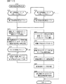
図14は、演出制御プロセス処理における演出図柄変動中処理(S75)を示すフローチャートである。演出図柄変動中処理において、演出制御用CPU120は、変動プロセスタイマ、変動時間タイマ、変動制御タイマのそれぞれの値を−1する(S301,S302,S303)。   FIG. 14 is a flowchart showing the effect symbol change process (S75) in the effect control process process. In the effect symbol fluctuation process, the effect control CPU 120 decrements each value of the fluctuation process timer, the fluctuation time timer, and the fluctuation control timer (S301, S302, S303).

S304において演出制御用CPU120は、変動プロセスタイマがタイマアウトしたか否か確認する。変動プロセスタイマがタイマアウトしていたら(S304;Y)、変動プロセスデータの切り替えを行う(S305)。即ち、プロセステーブルにおける次に設定されているプロセスタイマ設定値を変動プロセスタイマに設定することによって変動プロセスタイマをあらためてスタートさせる(S306)。また、その次に設定されている表示制御実行データ、LED制御実行データ、音制御実行データ、可動役物制御実行データ、操作部制御実行データ等にもとづいて演出装置(演出用部品)に対する制御状態を変更する(S307)。一方、変動プロセスタイマがタイマアウトしていない場合(S304;N)は、変動プロセスタイマに対応する変動プロセスデータの内容(表示制御実行データ、LED制御実行データ、音制御実行データ、可動役物制御実行データ、操作部制御実行データ等)に従って演出装置(演出用部品)の制御を実行する(S308)。   In S304, effect control CPU 120 checks whether or not the variable process timer has expired. If the variable process timer is out (S304; Y), the variable process data is switched (S305). That is, the variable process timer is restarted by setting the next set process timer value in the process table to the variable process timer (S306). Further, the control state for the rendering device (producing component) based on the display control execution data, LED control execution data, sound control execution data, movable accessory control execution data, operation unit control execution data, etc. Is changed (S307). On the other hand, if the variable process timer has not expired (S304; N), the contents of the variable process data corresponding to the variable process timer (display control execution data, LED control execution data, sound control execution data, movable accessory control) The control of the effect device (effect component) is executed according to the execution data, the operation unit control execution data, and the like (S308).

次に、演出制御用CPU120は、当該変動表示の変動パターンがスーパーリーチの変動パターンであるか否かを判定する(S309)。当該変動表示の変動パターンがスーパーリーチの変動パターンでない場合(S309;N)はS324に進み、当該変動表示の変動パターンがスーパーリーチの変動パターンである場合(S309;Y)は、プッシュボタン31Bの操作が受け付けられたことを示すプッシュボタン操作受付フラグがセットされているか否かを判定する(S310)。プッシュボタン操作受付フラグがセットされている場合(S310;Y)はS323に進み、プッシュボタン操作受付フラグがセットされていない場合は、プッシュボタン31Bの突出状態への変化が決定されているか否かを判定する(S311)。   Next, effect control CPU 120 determines whether or not the variation pattern of the variation display is a variation pattern of super reach (S309). If the variation pattern of the variable display is not the super-reach variation pattern (S309; N), the process proceeds to S324, and if the variation pattern of the variable display is the super-reach variation pattern (S309; Y), the push button 31B is pressed. It is determined whether or not a push button operation reception flag indicating that the operation has been received is set (S310). If the push button operation reception flag is set (S310; Y), the process proceeds to S323, and if the push button operation reception flag is not set, whether or not the change of the push button 31B to the protruding state is determined. Is determined (S311).

プッシュボタン31Bの突出状態への変化が決定されていない場合(S311;N)はS314に進み、プッシュボタン31Bの突出状態への変化が決定されている場合(S311;Y)は、変動プロセスデータを参照してボタン駆動モータ303の駆動期間中であるか否かを判定する(S312)。ボタン駆動モータ303の駆動期間中でない場合(S312;N)はS314に進み、ボタン駆動モータ303の駆動期間中である場合(S312;Y)は、ボタン駆動モータ303を駆動させてS314に進む(S313)。   If the change of the push button 31B to the protruding state is not determined (S311; N), the process proceeds to S314, and if the change of the push button 31B to the protruding state is determined (S311; Y), the variation process data It is determined whether or not the driving period of the button driving motor 303 is during (S312). If the driving period of the button driving motor 303 is not in progress (S312; N), the process proceeds to S314. If the driving period of the button driving motor 303 is in progress (S312; Y), the button driving motor 303 is driven and the process proceeds to S314 (S314). S313).

S314において演出制御用CPU120は、変動プロセスデータを参照してプッシュボタン31Bの操作受付開始タイミングであるか否かを判定する。プッシュボタン31Bの操作受付開始タイミングでない場合(S314;N)はS316に進み、プッシュボタン31Bの操作受付開始タイミングである場合(S314;Y)は、プッシュボタン31Bの突出の有無(プッシュボタン31Bを突出状態に変化させるか否かの決定)に応じた操作促進画像の表示を演出表示装置5にて開始する(S315a)。また、遊技者に対してプッシュボタン31Bの操作を促す操作促進メッセージの表示を演出表示装置5にて開始する(S315b)。そして、S316に進む。   In S314, the effect control CPU 120 determines whether or not it is the operation start timing of the operation of the push button 31B with reference to the fluctuation process data. If it is not the operation reception start timing of the push button 31B (S314; N), the process proceeds to S316, and if it is the operation reception start timing of the push button 31B (S314; Y), the presence or absence of the protrusion of the push button 31B (the push button 31B The effect display device 5 starts displaying the operation promotion image according to the determination of whether or not to change to the protruding state) (S315a). The effect display device 5 starts displaying an operation prompting message for prompting the player to operate the push button 31B (S315b). Then, the process proceeds to S316.

S316において演出制御用CPU120は、変動プロセスデータを参照してプッシュボタン31Bの操作受付期間中であるか否かを判定する。プッシュボタン31Bの操作受付期間中でない場合(S316;N)はS324に進み、プッシュボタン31Bの操作受付期間中である場合(S316;Y)は、更に、プッシュボタン31Bの操作受付有りか否か(プッシュボタン31Bが操作されたか否か)を判定する(S317)。尚、本実施例においてプッシュボタン31Bが操作されたことを判定するタイミングは、プッシュセンサ35が遊技者によるプッシュボタン31Bの操作終了を検出したタイミングであるが、本発明はこれに限定されるものではなく、プッシュボタン31Bが操作されたことを判定するタイミングは、プッシュセンサ35が遊技者によるプッシュボタン31Bの操作開始を検出したタイミングであってもよい。   In S316, the effect control CPU 120 determines whether or not the operation acceptance period of the push button 31B is being received with reference to the fluctuation process data. If it is not during the operation reception period of the push button 31B (S316; N), the process proceeds to S324, and if it is during the operation reception period of the push button 31B (S316; Y), it is further determined whether there is an operation reception of the push button 31B. It is determined whether or not the push button 31B has been operated (S317). In this embodiment, the timing for determining that the push button 31B has been operated is the timing at which the push sensor 35 detects the end of the operation of the push button 31B by the player, but the present invention is not limited to this. Instead, the timing for determining that the push button 31B has been operated may be the timing at which the push sensor 35 detects the start of operation of the push button 31B by the player.

また、本実施例では、後述するように、遊技者によるプッシュボタン31Bの操作に基づいて可動役物400が退避位置から演出位置に移動(落下)することにより変動表示結果が大当りとなることを報知する形態を例示しているが、本発明はこれに限定されるものではなく、遊技者によるプッシュボタン31Bの操作態様は、短期間での1回操作(単発押し)の他、継続操作(長押し)や複数回操作(連打)等のうち、いずれか1の操作態様のみを設けてもよいし、複数の操作態様を設けてもよい。   Further, in the present embodiment, as will be described later, the movable display 400 moves (falls) from the evacuation position to the production position based on the operation of the push button 31B by the player, and the variable display result becomes a big hit. Although the notification mode is exemplified, the present invention is not limited to this, and the operation mode of the push button 31B by the player is not limited to one-time operation (single-press) in a short period, but a continuous operation ( Of the operations such as long press) and multiple operations (continuous hit), only one operation mode may be provided, or a plurality of operation modes may be provided.

プッシュボタン31Bの操作受付有りの場合(S317;Y)はS321aに進み、プッシュボタン31Bの操作受付無しの場合(S317;N)は、更にプッシュボタン31Bの操作受付終了タイミングであるか否かを判定する(S319)。プッシュボタン31Bの操作受付終了タイミングである場合(S319;Y)はS321aに進み、プッシュボタン31Bの操作受付終了タイミングでない場合(S319;N)はS322に進む。   If the operation of the push button 31B is received (S317; Y), the process proceeds to S321a. If the operation of the push button 31B is not received (S317; N), it is further determined whether or not it is the operation reception end timing of the push button 31B. A determination is made (S319). When it is the operation reception end timing of the push button 31B (S319; Y), the process proceeds to S321a, and when it is not the operation reception end timing of the push button 31B (S319; N), the process proceeds to S322.

S321aにおいて演出制御用CPU120は、プッシュボタン31Bの操作受付期間中にプッシュボタン31Bが操作されたこと、または、プッシュボタン31Bが操作されることなくプッシュボタン31Bの操作受付期間が終了したことに基づいてプッシュボタン操作受付フラグをセットする。また、演出表示装置5における操作促進画像の表示を維持しつつ操作促進メッセージの表示を終了してS322に進む(S321b)。   In S321a, the effect control CPU 120 determines whether the push button 31B has been operated during the push button 31B operation accepting period, or that the operation accepting period of the push button 31B has ended without operating the push button 31B. To set the push button operation acceptance flag. Further, the display of the operation promotion message is ended while the display of the operation promotion image on the effect display device 5 is maintained, and the process proceeds to S322 (S321b).

S322において演出制御用CPU120は、プッシュボタン操作受付フラグがセットされているか否かを判定する。プッシュボタン操作受付フラグがセットされている場合(S322;Y)はS323に進み、プッシュボタン操作受付フラグがセットされていない場合はS324に進む。尚、S323において演出制御用CPU120は、プッシュボタン31Bの操作受付期間中にプッシュボタン31Bが操作されたこと、または、プッシュボタン31Bが操作されることなくプッシュボタン31Bの操作受付期間が終了したことに基づいて操作後演出を実行するための操作後演出実行処理を実行してS324に進む。   In S322, effect control CPU 120 determines whether or not the push button operation reception flag is set. When the push button operation reception flag is set (S322; Y), the process proceeds to S323, and when the push button operation reception flag is not set, the process proceeds to S324. In S323, the effect control CPU 120 determines that the push button 31B has been operated during the operation reception period of the push button 31B, or that the operation reception period of the push button 31B has ended without operating the push button 31B. , An after-operation effect execution process for executing the after-operation effect is executed, and the process proceeds to S324.

次に、変動制御タイマがタイマアウトしているか否かを確認する(S324)。変動制御タイマがタイマアウトしている場合には(S324;Y)、演出制御用CPU120は、左中右の演出図柄の次表示画面(前回の演出図柄の表示切り替え時点から30ms経過後に表示されるべき画面)の画像データを作成し、VRAMの所定領域に書き込む(S325)。そのようにして、演出表示装置5において、演出図柄の変動制御が実現される。表示制御部123は、設定されている背景画像等の所定領域の画像データと、プロセステーブルに設定されている表示制御実行データにもとづく画像データとを重畳したデータに基づく信号を演出表示装置5に出力する。そのようにして、演出表示装置5において、演出図柄の変動における背景画像、キャラクタ画像及び演出図柄が表示される。また、変動制御タイマに所定値を再セットする(S326)。   Next, it is confirmed whether or not the fluctuation control timer has expired (S324). If the variation control timer is out (S324; Y), the effect control CPU 120 displays the next display screen of the left-middle-right effect symbol (30 ms after the previous display symbol switching time of the effect symbol). The image data of the screen to be processed is created and written in a predetermined area of the VRAM (S325). In this way, in the effect display device 5, the fluctuation control of the effect symbol is realized. The display control unit 123 transmits to the effect display device 5 a signal based on data obtained by superimposing image data of a predetermined area such as a set background image and image data based on display control execution data set in a process table. Output. In this way, the effect display device 5 displays the background image, the character image, and the effect design in the variation of the effect design. Further, a predetermined value is reset in the fluctuation control timer (S326).

また、変動制御タイマがタイマアウトしていない場合(S324;N)、S326の実行後、演出制御用CPU120は、変動時間タイマがタイマアウトしているか否か確認する(S327)。変動時間タイマがタイマアウトしていれば、演出制御プロセスフラグの値を演出図柄変動停止処理(S76)に応じた値に更新する(S329)。変動時間タイマがタイマアウトしていなくても、図柄確定指定コマンドを受信したことを示す確定コマンド受信フラグがセットされていたら(S328;Y)、演出制御プロセスフラグの値を演出図柄変動停止処理(S76)に応じた値に更新する(S329)。変動時間タイマがタイマアウトしていなくても図柄確定指定コマンドを受信したら変動を停止させる制御に移行するので、例えば、基板間でのノイズ等に起因して長い変動時間を示す変動パターン指定コマンドを受信したような場合でも、正規の変動時間経過時(特別図柄の変動終了時)に、演出図柄の変動を終了させることができる。   If the variation control timer has not expired (S324; N), after executing S326, the effect control CPU 120 checks whether the variation time timer has expired (S327). If the variation time timer is out, the value of the effect control process flag is updated to a value according to the effect symbol variation stop processing (S76) (S329). Even if the fluctuation time timer has not expired, if the confirmation command reception flag indicating that the symbol confirmation designation command has been received is set (S328; Y), the value of the production control process flag is changed to the production symbol fluctuation stop processing (S328). The value is updated to a value corresponding to S76) (S329). Even if the fluctuation time timer is not out of timer, the control shifts to control to stop the fluctuation when the symbol confirmation designation command is received. For example, a fluctuation pattern specification command that indicates a long fluctuation time due to noise between boards, etc. Even in the case of receiving, the fluctuation of the effect symbol can be ended when the normal fluctuation time has elapsed (at the end of the fluctuation of the special symbol).

尚、演出図柄の変動制御に用いられているプロセステーブルには、演出図柄の変動表示中のプロセスデータが設定されている。つまり、プロセステーブルにおけるプロセスデータ1〜nのプロセスタイマ設定値の和は演出図柄の変動時間に相当する。よって、S304の処理において最後のプロセスデータnのプロセスタイマがタイマアウトしたときには、切り替えるべきプロセスデータ(表示制御実行データやLED制御実行データ等)はなく、プロセステーブルにもとづく演出図柄の演出制御は終了する。   In the process table used for effect symbol variation control, process data during the effect symbol variation display is set. That is, the sum of the process timer set values of the process data 1 to n in the process table corresponds to the fluctuation time of the effect symbol. Therefore, when the process timer of the last process data n has timed out in the process of S304, there is no process data to be switched (display control execution data, LED control execution data, etc.), and the effect control of the effect symbol based on the process table ends. I do.

図15は、演出図柄変動中処理における操作後演出実行処理(S323)を示すフローチャートである。操作後演出実行処理において、演出制御用CPU120は、先ず、操作後演出プロセスタイマが動作中であるか否かを判定する(S401)。操作後演出プロセスタイマが動作中である場合(S401;Y)はS408に進み、操作後演出プロセスタイマが動作中でない場合(S401;N)は、変動表示結果が大当りであるか否かを判定する(S402)。変動表示結果が大当りである場合(S402;Y)は大当り用の操作後演出プロセステーブルを選択し(S403)、変動表示結果がはずれである場合(S402;N)ははずれ用の操作後演出プロセステーブルを選択する(S404)。   FIG. 15 is a flowchart showing the post-operation effect execution process (S323) in the effect symbol change process. In the post-operation effect execution process, the effect control CPU 120 first determines whether or not the post-operation effect process timer is operating (S401). If the post-operation effect process timer is operating (S401; Y), the process proceeds to S408, and if the post-operation effect process timer is not operating (S401; N), it is determined whether the variable display result is a big hit. (S402). If the variable display result is a big hit (S402; Y), the post-operation effect process table for the big hit is selected (S403). If the variable display result is a miss (S402; N), the post-operation effect process for the big hit is selected. A table is selected (S404).

そして、S403またはS404の実行後は、選択した操作後演出プロセステーブルのプロセスデータ1における操作後演出プロセスタイマをスタートさせる(S405)。   Then, after execution of S403 or S404, the post-operation effect process timer in the process data 1 of the selected post-operation effect process table is started (S405).

尚、操作後演出プロセステーブルには、演出表示装置5の表示を制御するための表示制御実行データ、各LEDの点灯を制御するためのLED制御実行データ、スピーカ8L,8Rから出力する音の制御するための音制御実行データや、可動役物400の動作を制御するための可動役物制御実行データ等が、各プロセスデータn(1〜N番まで)に対応付けて時系列に順番配列されている。   The post-operation effect process table includes display control execution data for controlling the display of the effect display device 5, LED control execution data for controlling the lighting of each LED, and control of the sound output from the speakers 8L and 8R. Sound control execution data for controlling the operation of the movable accessory 400 and the movable accessory control execution data for controlling the operation of the movable accessory 400 are arranged in time series in association with each process data n (1 to N). ing.

次いで、演出制御用CPU120は、操作後演出プロセスデータ1の内容(表示制御実行データ1、LED制御実行データ1、音制御実行データ1、可動役物制御実行データ1、)に従って演出装置(演出用部品としての演出表示装置5、演出用部品としての各種LED及び演出用部品としてのスピーカ8L,8R、可動役物400等))の制御を実行する(S406)。例えば、演出表示装置5において変動表示結果に応じた画像を表示させるために、表示制御部123に指令を出力する。また、各種LEDを点灯/消灯制御を行わせるために、LED制御基板14に対して制御信号(LED制御実行データ)を出力する。また、スピーカ8L,8Rからの音声出力を行わせるために、音声制御基板13に対して制御信号(音番号データ)を出力する。また、可動役物400を動作させるために、可動役物第1駆動モータ301や可動役物第2駆動モータ302を駆動させる。また、演出表示装置5に表示されている操作促進画像を操作後画像として更新を開始して操作後演出実行処理を終了する(S407)。   Next, the effect control CPU 120 performs the effect device (for the effect control) in accordance with the contents of the post-operation effect process data 1 (display control execution data 1, LED control execution data 1, sound control execution data 1, movable accessory control execution data 1). The control of the effect display device 5 as a part, various LEDs as effect parts and the speakers 8L and 8R as the effect parts, the movable role 400, etc.) is executed (S406). For example, a command is output to the display control unit 123 in order to cause the effect display device 5 to display an image according to the result of the variable display. In addition, a control signal (LED control execution data) is output to the LED control board 14 in order to control the turning on / off of various LEDs. Further, a control signal (sound number data) is output to the sound control board 13 in order to output sounds from the speakers 8L and 8R. In addition, in order to operate the movable accessory 400, the movable accessory first drive motor 301 and the movable accessory second drive motor 302 are driven. Also, the update is started with the operation promotion image displayed on the effect display device 5 as the post-operation image, and the post-operation effect execution process ends (S407).

また、S408において演出制御用CPU120は、操作後演出プロセスタイマの値を−1する。そして、操作後演出プロセスタイマがタイマアウトしたか否かを判定する(S409)。操作後演出プロセスタイマがタイマアウトした場合(S409;Y)は、操作後演出プロセスデータの切り替えを行う(S410)。即ち、操作後演出プロセステーブルにおける次に設定されているプロセスタイマ設定値を操作後演出プロセスタイマに設定することによって操作後演出プロセスタイマをあらためてスタートさせる(S411)。また、その次に設定されている表示制御実行データ、LED制御実行データ、音制御実行データ、可動役物制御実行データ等にもとづいて演出装置(演出用部品)に対する制御状態を変更する(S412)。一方、操作後演出プロセスタイマがタイマアウトしていない場合(S409;N)は、操作後演出プロセスタイマに対応する操作後演出プロセスデータの内容(表示制御実行データ、LED制御実行データ、音制御実行データ、可動役物制御実行データ等)に従って演出装置(演出用部品)の制御を実行する(S413)。   In S408, the effect control CPU 120 decrements the value of the post-operation effect process timer by one. Then, it is determined whether or not the post-production effect process timer has expired (S409). When the post-operation effect process timer has expired (S409; Y), the post-operation effect process data is switched (S410). That is, the post-operation effect process timer is started again by setting the next set process timer value in the post-operation effect process table as the post-operation effect process timer (S411). In addition, the control state of the effect device (effect component) is changed based on the display control execution data, the LED control execution data, the sound control execution data, the movable accessory control execution data, etc. which are set next (S412). . On the other hand, if the post-operation effect process timer has not expired (S409; N), the contents of the post-operation effect process data corresponding to the post-operation effect process timer (display control execution data, LED control execution data, sound control execution) The control of the rendering device (the rendering component) is executed in accordance with the data, the movable object control execution data, and the like (S413).

そして、S412またはS413の実行後は、演出表示装置5に表示されている操作後画像を更新し(S414)、変動表示結果が大当りであるか否かを判定する(S415)。変動表示結果がはずれである場合(S415;N)は操作後演出実行処理を終了し、変動表示結果が大当りである場合(S415;Y)は、可動役物第1駆動モータ301の正転駆動期間中であるか否か、つまり、可動役物400の退避位置から演出位置に向けての移動期間中であるか否かを判定する(S416)。可動役物第1駆動モータ301の正転駆動期間中である場合(S416;Y)は可動役物第1駆動モータ301を正転駆動させることによって可動役物400を演出位置に向けて移動させ、S418に進む(S417)。また、可動役物第1駆動モータ301の正転駆動期間中でない場合(S416;N)は、S417を経由することなくS418に進む。   Then, after execution of S412 or S413, the post-operation image displayed on the effect display device 5 is updated (S414), and it is determined whether or not the variable display result is a big hit (S415). If the variable display result is out of order (S415; N), the effect execution process after the operation is terminated, and if the variable display result is a big hit (S415; Y), the forward rotation drive of the movable accessory first drive motor 301 is performed. It is determined whether it is during the period, that is, whether it is during the moving period from the retreat position of movable movable object 400 to the rendering position (S416). In the case of the normal rotation drive period of the movable accessory first drive motor 301 (S416; Y), the movable accessory 400 is moved toward the production position by rotating the movable accessory first drive motor 301 forward. , S418 (S417). In addition, when it is not during the normal rotation drive period of the movable accessory first drive motor 301 (S416; N), the process proceeds to S418 without passing through S417.

S418において演出制御用CPU120は、可動役物第1駆動モータ301の逆転駆動期間中であるか否か、つまり、可動役物400の演出位置から退避位置に向けての移動期間中であるか否かを判定する。可動役物第1駆動モータ301の逆転駆動期間中である場合(S418;Y)は、可動役物第1駆動モータ301を逆転駆動させることによって可動役物400を退避位置に向けて移動させ、S420に進む(S419)。また、可動役物第1駆動モータ301の逆転駆動期間中でない場合(S418;N)は、S419を経由することなくS420に進む。   In S418, effect control CPU 120 determines whether or not the movable accessory first drive motor 301 is in the reverse rotation period, that is, whether or not movable accessory 400 is moving from the effect position to the retreat position. Is determined. During the reverse rotation driving period of the movable accessory first drive motor 301 (S418; Y), the movable accessory 400 is moved toward the retreat position by reversely driving the movable accessory first drive motor 301, The process proceeds to S420 (S419). In addition, when it is not during the reverse rotation drive period of the movable accessory first drive motor 301 (S418; N), the process proceeds to S420 without passing through S419.

S420において演出制御用CPU120は、可動役物第2駆動モータ302の正転駆動期間中であるか否か、つまり、可動役物400が演出位置に位置している状態において、可動役物400を第1可動部401と第2可動部402とが近接する近接状態から第1可動部401と第2可動部402とが離間する離間状態に変化させる期間中であるか否かを判定する。可動役物第2駆動モータ302の正転駆動期間中である場合(S420;Y)は、可動役物第2駆動モータ302を正転駆動させることによって可動役物400を離間状態に変化させるとともに(S421)、演出表示装置5に可動役物400が退避位置に移動したことに対応するエフェクト画像を表示してS423に進む(S422)。また、可動役物第2駆動モータ302の正転駆動期間中でない場合(S420;N)は、S421及びS422を経由せず、つまり、演出表示装置5でのプッシュボタン31Bの画像の表示中であれば、該プッシュボタン31Bの画像の表示を継続してS423に進む。   In S420, the effect control CPU 120 determines whether or not the movable auditors second drive motor 302 is in the forward rotation period, that is, in a state where the movable auditors 400 are located in the effect position, the movable auditors 400 It is determined whether or not it is during a period of changing from a close state in which the first movable section 401 and the second movable section 402 are close to a separated state in which the first movable section 401 and the second movable section 402 are separated. In the case of the normal rotation drive period of the movable accessory second drive motor 302 (S420; Y), the movable accessory 400 is changed to the separated state by rotating the movable accessory second drive motor 302 forward. (S421), an effect image corresponding to the movement of the movable accessory 400 to the retreat position is displayed on the effect display device 5, and the process proceeds to S423 (S422). When the movable actor second drive motor 302 is not in the normal rotation drive period (S420; N), the process does not go through S421 and S422, that is, while the image of the push button 31B is being displayed on the effect display device 5. If there is, the display of the image of the push button 31B is continued, and the process proceeds to S423.

S423において演出制御用CPU120は、可動役物第2駆動モータ302の逆転駆動期間中であるか否か、つまり、可動役物400が演出位置に位置している状態において第1可動部401及び第2可動部402の離間位置から近接位置に向けての移動期間中であるか否かを判定する。可動役物第2駆動モータ302の逆転駆動期間中である場合(S423;Y)は、可動役物第2駆動モータ302を逆転駆動させることによって第1可動部401及び第2可動部402を近接位置に向けて移動させて操作後演出実行処理を終了する(S424)。また、可動役物第2駆動モータ302の逆転駆動期間中でない場合(S423;N)は、S424を経由せずに操作後演出実行処理を終了する。   In S423, the effect control CPU 120 determines whether or not the movable accessory second drive motor 302 is in the reverse rotation period, that is, in the state where the movable accessory 400 is located at the effect position, the first movable portion 401 and the second movable (2) It is determined whether or not the moving period of the movable section 402 from the separated position to the close position is being performed. When the movable actor second drive motor 302 is in the reverse rotation period (S423; Y), the first movable portion 401 and the second movable portion 402 are brought close to each other by driving the movable accessory second drive motor 302 to rotate in the reverse direction. After moving to the position, the post-operation effect execution processing ends (S424). In addition, if it is not during the reverse rotation drive period of the movable auditors second drive motor 302 (S423; N), the post-operation effect execution process ends without going through S424.

以上のように演出制御用CPU120によって演出図柄変動開始処理、演出図柄変動中処理、操作後演出実行処理が実行されることによって、スーパーリーチの変動表示においてプッシュボタン31Bを突出させず(演出図柄変動開始処理のS278においてプッシュボタン31Bの非突出状態から突出状態への変化の非実行を決定した場合)変動表示結果が大当りとなる場合は、図16(A)に示すように、変動開始から期間L1が経過したタイミング(リーチ演出実行中のタイミング)から演出表示装置5に操作促進画像としての非突出状態のプッシュボタン31Bの画像と操作促進メッセージの表示が開始される。そして、プッシュボタン31Bの操作受付期間中にプッシュボタン31Bが操作されるかプッシュボタン31Bが操作されることなく該操作受付期間が経過した場合は、プッシュボタン31Bの操作を受け付けたタイミング、または、プッシュボタン31Bの操作受付期間が終了したタイミングにおいて操作促進メッセージの表示が終了する。   As described above, the effect control CPU 120 executes the effect symbol variation start process, the effect symbol variation process, and the post-operation effect execution process, so that the push button 31B is not projected in the variation display of the super reach (effect symbol variation). If it is determined in step S278 of the start process that the change of the push button 31B from the non-protruding state to the protruding state is not to be performed) If the fluctuation display result is a big hit, as shown in FIG. The display of the image of the push button 31B in the non-projecting state as the operation prompting image and the operation prompting message on the effect display device 5 is started from the timing when L1 has elapsed (timing during the execution of the reach rendering). Then, when the push button 31B is operated during the operation reception period of the push button 31B or the operation reception period elapses without the push button 31B being operated, the timing at which the operation of the push button 31B is received, or The display of the operation prompting message ends when the operation reception period of the push button 31B ends.

また、プッシュボタン31Bの操作を受け付けたタイミング、または、プッシュボタン31Bの操作受付期間が終了したタイミングから期間L2に亘って、操作促進画像(非突出状態のプッシュボタン31Bの画像)である操作後画像が演出表示装置5から消去される。更に、プッシュボタン31Bの操作を受け付けたタイミング、または、プッシュボタン31Bの操作受付期間が終了したタイミングから期間L2よりも長い期間である期間L3に亘って、可動役物400を図1に示す退避位置から演出表示装置5と重畳する演出位置に向けての移動(落下)が実行される。   Further, after the operation that is the operation promotion image (the image of the push button 31B in the non-projecting state) from the timing at which the operation of the push button 31B is received or the timing at which the operation reception period of the push button 31B ends, over a period L2. The image is deleted from the effect display device 5. Further, the movable role 400 is retracted as shown in FIG. 1 from the timing when the operation of the push button 31B is received or the period L3 that is longer than the period L2 from the timing when the operation receiving period of the push button 31B ends. The movement (fall) from the position to the effect position superimposed on the effect display device 5 is executed.

可動役物400の演出位置への移動完了後は、第1可動部401及び第2可動部402を移動させることによって演出位置において可動役物400を近接状態から離間状態に変化させた後、可動役物400を離間状態から近接状態に変化させる。そして、再び可動役物400を演出位置から退避位置に移動させ、変動表示が終了する。   After the movement of the movable auditorium 400 to the production position is completed, the first movable part 401 and the second movable part 402 are moved to change the movable auditorium 400 from the close state to the separated state at the production position, and then move. The accessory 400 is changed from the separated state to the close state. Then, movable movable object 400 is moved from the production position to the retreat position again, and the variable display ends.

スーパーリーチの変動表示においてプッシュボタン31Bを突出させて(演出図柄変動開始処理のS278においてプッシュボタン31Bの非突出状態から突出状態への変化の実行を決定した場合)変動表示結果が大当りとなる場合は、図16(B)に示すように、変動開始から期間L1が経過したタイミング(リーチ演出実行中のタイミング)から演出表示装置5に操作促進画像としての突出状態のプッシュボタン31Bの画像と操作促進メッセージの表示が開始される。尚、プッシュボタン31Bは、リーチ演出中における操作促進画像や操作促進メッセージの表示開始前タイミングの直前に非突出状態から突出状態に変化する。そして、プッシュボタン31Bの操作受付期間中にプッシュボタン31Bが操作されるかプッシュボタン31Bが操作されることなく該操作受付期間が経過した場合は、プッシュボタン31Bの操作を受け付けたタイミング、または、プッシュボタン31Bの操作受付期間が終了したタイミングにおいて操作促進メッセージの表示が終了する。   When the push button 31B is projected in the variation display of the super reach (when the execution of the change from the non-projection state to the projection state of the push button 31B is determined in S278 of the effect symbol variation start process), the variation display result is a big hit As shown in FIG. 16B, the image of the push button 31 </ b> B in the protruding state as an operation promotion image and the operation on the effect display device 5 from the timing when the period L <b> 1 has elapsed from the start of the fluctuation (the timing during execution of the reach effect). The display of the prompt message is started. Note that the push button 31B changes from the non-projecting state to the projecting state immediately before the timing before the display of the operation promotion image or the operation promotion message starts during the reach effect. Then, when the push button 31B is operated during the operation reception period of the push button 31B or the operation reception period elapses without the push button 31B being operated, the timing at which the operation of the push button 31B is received, or The display of the operation prompting message ends when the operation reception period of the push button 31B ends.

また、プッシュボタン31Bの操作を受け付けたタイミング、または、プッシュボタン31Bの操作受付期間が終了したタイミングから期間L3に亘って、可動役物400を図1に示す退避位置から演出表示装置5と重畳する演出位置に向けての移動(落下)が実行される。   Also, the movable role 400 is superimposed on the effect display device 5 from the retracted position shown in FIG. 1 over a period L3 from the timing at which the operation of the push button 31B is received or the timing at which the operation receiving period of the push button 31B ends. (Fall) toward the effect position to be performed.

更に、可動役物400の退避位置から演出位置への移動(落下)期間中は、操作後演出として、操作促進画像(突出状態のプッシュボタン31Bの画像)である操作後画像を、非突出状態のプッシュボタン31Bの画像に更新する。このように、可動役物400の退避位置から演出位置への移動に併せて操作後演出を実行することで、遊技者に対してあたかも落下する可動役物400が突出状態のプッシュボタン31Bの画像を操作して非突出状態に変化させるように見せることができる。   Further, during the period of movement (fall) of the movable auditorium 400 from the retracted position to the rendering position, the post-operation image, which is the operation promotion image (the image of the push button 31B in the protruding state), is displayed as the post-operation effect. Is updated to the image of the push button 31B. As described above, by performing the post-operation effect in conjunction with the movement of the movable auditorium 400 from the retracted position to the rendering position, the image of the push button 31B in which the movable auditorium 400 that falls as if to fall on the player is projected. Can be operated to change to a non-projecting state.

尚、本実施例では、操作後画像である突出状態のプッシュボタン31Bの画像を非突出状態のプッシュボタン31Bの画像に更新することによって、落下する可動役物400が突出状態のプッシュボタン31Bの画像を操作して非突出状態に変化させるように見せる形態を例示しているが、本発明はこれに限定されるものではなく、操作後画像である突出状態のプッシュボタン31Bの画像は、可動役物400が突出状態のプッシュボタン31Bの画像を操作するように遊技者に対して見せかけることができるのであれば非突出状態のプッシュボタン31Bの画像とは異なる画像に更新するようにしてもよい。   In the present embodiment, the image of the push button 31B in the protruding state, which is the post-operation image, is updated to the image of the push button 31B in the non-protruding state. Although the mode in which the image is changed to the non-projected state by operating the image is illustrated, the present invention is not limited to this. The image of the pushed push button 31B that is the post-operation image is movable. If it is possible to make the player seem to operate the image of the push button 31B in the protruding state, the image may be updated to an image different from the image of the push button 31B in the non-protruding state. .

操作後演出として操作後画像である非突出状態のプッシュボタン31Bの画像の更新が終了した後は、該非突出状態のプッシュボタン31Bの画像が期間L2に亘って演出表示装置5から消去される。尚、本実施例では、図16(B)に示すように、突出状態から非突出状態に変化した後のプッシュボタン31Bの画像の消去が終了するタイミングが可動役物400の退避位置から演出位置への移動完了タイミングと同一タイミングとなっているが、本発明はこれに限定されるものではなく、突出状態から非突出状態に変化した後のプッシュボタン31Bの画像の消去が終了するタイミングと可動役物400の退避位置から演出位置への移動完了タイミングとは異なるタイミングであってもよい。   After the update of the image of the non-projecting push button 31B, which is the post-operation image, as the post-operation effect, the image of the non-projecting push button 31B is deleted from the effect display device 5 over the period L2. In the present embodiment, as shown in FIG. 16B, the timing at which the erasure of the image of the push button 31B after the change from the protruding state to the non-protruding state ends is determined from the retracted position of the movable role 400 to the production position. The timing is the same as the movement completion timing, but the present invention is not limited to this, and the timing at which the deletion of the image of the push button 31B after the change from the protruding state to the non-protruding state ends and the The timing may be different from the timing of completing the movement of the accessory 400 from the retreat position to the production position.

可動役物400の演出位置への移動完了後は、第1可動部401及び第2可動部402を移動させることによって演出位置において可動役物400を近接状態から離間状態に変化させる。尚、可動役物400の離間状態への変化が完了したタイミングでは、演出表示装置5に、可動役物400が演出位置において離間状態に変化したことを示すエフェクト画像を表示する。そして、可動役物400を離間状態から近接状態に変化させた後、再び可動役物400を演出位置から退避位置に移動させ、変動表示が終了する。   After the completion of the movement of the movable auditorium 400 to the rendering position, the movable member 400 is changed from the close state to the separated state at the rendering position by moving the first movable part 401 and the second movable part 402. At the timing when the change of the movable auditorium 400 to the separated state is completed, an effect image indicating that the movable auditorium 400 has changed to the separated state at the rendering position is displayed on the effect display device 5. Then, after changing the movable auditors 400 from the separated state to the closer state, the movable auditors 400 are again moved from the production position to the retreat position, and the variable display ends.

スーパーリーチの変動表示においてプッシュボタン31Bを突出させず(演出図柄変動開始処理のS278においてプッシュボタン31Bの非突出状態から突出状態への変化の非実行を決定した場合)変動表示結果がはずれとなる場合は、図17(A)に示すように、変動開始から期間L1が経過したタイミング(リーチ演出実行中のタイミング)から演出表示装置5に操作促進画像としての非突出状態のプッシュボタン31Bの画像と操作促進メッセージの表示が開始される。そして、プッシュボタン31Bの操作受付期間中にプッシュボタン31Bが操作されるかプッシュボタン31Bが操作されることなく該操作受付期間が経過した場合は、プッシュボタン31Bの操作を受け付けたタイミング、または、プッシュボタン31Bの操作受付期間が終了したタイミングにおいて操作促進メッセージの表示が終了する。   In the super-reach change display, the push button 31B is not protruded (when the non-execution of the change from the non-projection state to the protrusion state of the push button 31B is determined in S278 of the effect symbol change start process), the change display result is incorrect. In the case, as shown in FIG. 17A, the image of the push button 31B in the non-projecting state as the operation promotion image is displayed on the effect display device 5 from the timing when the period L1 has elapsed from the start of the change (the timing during the execution of the reach effect). And the display of the operation prompt message is started. Then, when the push button 31B is operated during the operation reception period of the push button 31B or the operation reception period elapses without the push button 31B being operated, the timing at which the operation of the push button 31B is received, or The display of the operation prompting message ends when the operation reception period of the push button 31B ends.

また、プッシュボタン31Bの操作を受け付けたタイミング、または、プッシュボタン31Bの操作受付期間が終了したタイミングから期間L2に亘って、操作促進画像(非突出状態のプッシュボタン31Bの画像)である操作後画像が演出表示装置5から消去される。そして、可動役物400が退避位置から演出位置に向けて移動(落下することなく)変動表示が終了する。   Further, after the operation that is the operation promotion image (the image of the push button 31B in the non-projecting state) from the timing at which the operation of the push button 31B is received or the timing at which the operation reception period of the push button 31B ends, over a period L2. The image is deleted from the effect display device 5. Then, the moving display of the movable auditorium 400 from the retreat position to the effect position (without dropping) ends.

スーパーリーチの変動表示においてプッシュボタン31Bを突出させて(演出図柄変動開始処理のS278においてプッシュボタン31Bの非突出状態から突出状態への変化の実行を決定した場合)変動表示結果がはずれとなる場合は、図17(B)に示すように、変動開始から期間L1が経過したタイミング(リーチ演出実行中のタイミング)から演出表示装置5に操作促進画像としての突出状態のプッシュボタン31Bの画像と操作促進メッセージの表示が開始される。尚、プッシュボタン31Bは、リーチ演出中における操作促進画像や操作促進メッセージの表示開始前タイミングの直前に非突出状態から突出状態に変化する。そして、プッシュボタン31Bの操作受付期間中にプッシュボタン31Bが操作されるかプッシュボタン31Bが操作されることなく該操作受付期間が経過した場合は、プッシュボタン31Bの操作を受け付けたタイミング、または、プッシュボタン31Bの操作受付期間が終了したタイミングにおいて操作促進メッセージの表示が終了する。   When the push button 31B is projected in the variation display of the super reach (when the execution of the change from the non-projection state to the projection state of the push button 31B is determined in S278 of the effect symbol variation start process), the variation display result is incorrect. As shown in FIG. 17B, the image of the push button 31 </ b> B in the protruding state as the operation promotion image and the operation on the effect display device 5 from the timing when the period L <b> 1 has elapsed since the start of the fluctuation (the timing during the execution of the reach effect) The display of the prompt message is started. Note that the push button 31B changes from the non-projecting state to the projecting state immediately before the timing before the display of the operation promotion image or the operation promotion message starts during the reach effect. Then, when the push button 31B is operated during the operation reception period of the push button 31B or the operation reception period elapses without the push button 31B being operated, the timing at which the operation of the push button 31B is received, or The display of the operation prompting message ends when the operation reception period of the push button 31B ends.

そして、プッシュボタン31Bの操作を受け付けたタイミング、または、プッシュボタン31Bの操作受付期間が終了したタイミングから期間L2に亘って、操作促進画像(突出状態のプッシュボタン31Bの画像)である操作後画像が演出表示装置5から消去される。そして、可動役物400が退避位置から演出位置に向けて移動(落下)することなく変動表示が終了する。   Then, the post-operation image which is the operation promotion image (the image of the push button 31B in the protruding state) from the timing when the operation of the push button 31B is received or the timing when the operation reception period of the push button 31B ends to the period L2. Is deleted from the effect display device 5. Then, the variable display ends without moving (falling) the movable auditorium 400 from the retreat position toward the effect position.

次に、スーパーリーチの変動表示においてプッシュボタン31Bを突出させることが決定されている場合での演出表示装置5の表示態様及び可動役物400の動作態様について図18及び図19に基づいて説明する。   Next, a display mode of the effect display device 5 and an operation mode of the movable accessory 400 in a case where it is determined that the push button 31B is projected in the fluctuation display of the super reach will be described with reference to FIGS. .

先ず、図18(A)〜図18(D)に示すように、可動役物400が退避位置に配置されている状態において演出図柄がリーチの組み合わせとなると、演出表示装置5においてリーチ演出(スーパーリーチ演出)が開始される。該スーパーリーチ演出中は、所定時間が経過すると、ボタン駆動モータ303の駆動によって非突出状態のプッシュボタン31Bが突出状態に変化する。そして、図18(E)に示すように、演出表示装置5に操作促進画像として突出状態のプッシュボタン31Bの画像と「押せ!!」等の操作促進メッセージが表示され、プッシュボタン31Bの操作の受け付けが開始される。   First, as shown in FIGS. 18 (A) to 18 (D), when the effect design is a combination of reach in a state where the movable auditorium 400 is arranged at the retreat position, the reach effect (super Reach production) is started. During the super-reach effect, after a predetermined time has elapsed, the push button 31B in the non-projected state is changed to the projected state by driving the button driving motor 303. Then, as shown in FIG. 18 (E), an image of the protruding push button 31B and an operation promotion message such as “Press!” Are displayed on the effect display device 5 as the operation promotion image, and the operation of the push button 31B is operated. Reception is started.

プッシュボタン31Bの操作受付期間中に遊技者がプッシュボタン31Bを操作する、または、遊技者がプッシュボタン31Bを操作することなくプッシュボタン31Bの操作受付期間が終了すると、図19(F)〜図19(H)に示すように、演出表示装置5から操作促進メッセージが消去され、可動役物400が退避位置から演出位置に向けて移動(落下)を開始する。更に、該可動役物400の移動(落下)に連動して、操作後画像としての突出状態のプッシュボタン31Bの画像が非突出状態のプッシュボタン31Bの画像に漸次更新されている。   When the player operates the push button 31B during the operation reception period of the push button 31B, or when the operation reception period of the push button 31B ends without the player operating the push button 31B, FIGS. As shown in FIG. 19 (H), the operation prompting message is deleted from the effect display device 5, and the movable role 400 starts moving (falling) from the retracted position to the effect position. Further, in conjunction with the movement (fall) of the movable role 400, the image of the push button 31B in the protruding state as the post-operation image is gradually updated to the image of the push button 31B in the non-protruding state.

そして、図19(I)及び図19(J)に示すように、可動役物400の演出位置への移動(落下)と非突出状態のプッシュボタン31Bの画像への更新が完了すると、演出表示装置5での操作後画像として非突出状態のプッシュボタン31Bの画像の表示が終了され、可動役物400が近接状態から離間状態に変化する。また、演出表示装置5にエフェクト画像を表示する。   Then, as shown in FIG. 19 (I) and FIG. 19 (J), when the movement (movement) of the movable auditorium 400 to the rendering position and the update of the non-projecting push button 31B to the image are completed, the rendering display is performed. The display of the image of the push button 31B in the non-projecting state as the post-operation image on the device 5 is ended, and the movable auditorium 400 changes from the close state to the separated state. The effect image is displayed on the effect display device 5.

以上、本実施例のパチンコ遊技機1にあっては、図19に示すように、遊技者が突出状態のプッシュボタン31Bを操作したことに基づいて、操作後演出として可動役物400を落下させるとともに演出表示装置5に表示されている突出状態のプッシュボタン31Bの画像を非突出状態のプッシュボタン31Bの画像に更新する(変化させる)ことによって、可動役物400があたかも突出状態のプッシュボタン31B画像を操作したように見せかけることができるので、これら可動役物400の動作とプッシュボタン31Bの画像の表示態様の変化との対応によって遊技興趣を向上できる。尚、本実施例では、操作促進画像である突出状態のプッシュボタン31Bの画像が変化する例として、非突出状態のプッシュボタン31Bの画像に更新される形態を開示しているが、本発明はこれに限定されるものではなく、操作促進画像である突出状態のプッシュボタン31Bの画像の変化には、該プッシュボタン31Bの画像が非突出状態のプッシュボタン31Bの画像に変化した後、更に演出表示装置5から消去されるまでを含んでもよい。   As described above, in the pachinko gaming machine 1 of the present embodiment, as shown in FIG. 19, based on the fact that the player has operated the protruding push button 31B, the movable role 400 is dropped as the post-operation effect. By updating (changing) the image of the push button 31B in the protruding state displayed on the effect display device 5 with the image of the push button 31B in the non-protruding state, the movable role 400 is as if the push button 31B is in the protruding state. Since it is possible to make it appear that the image has been manipulated, the entertainment of the game can be improved by the correspondence between the operation of the movable accessory 400 and the change in the display mode of the image of the push button 31B. Note that, in the present embodiment, as an example in which the image of the push button 31B in the protruding state, which is the operation promotion image, is changed to an image of the push button 31B in the non-protruding state. The present invention is not limited to this, and the image of the push button 31B in the protruding state, which is the operation promotion image, may be changed after the image of the push button 31B changes to the image of the push button 31B in the non-protruding state. It may include the time until the data is erased from the display device 5.

尚、本実施例では、可動役物400を落下させることによって可動役物400があたかも突出状態のプッシュボタン31Bの画像を操作したように見せかける形態を例示したが、本発明はこれに限定されるものではなく、突出状態のプッシュボタン31Bの画像を操作したように見せかけることが可能であれば、可動役物400の動作態様は落下以外であってもよい。   Note that, in the present embodiment, an example has been described in which the movable role 400 is made to fall to make it appear as if the image of the push button 31B in the protruding state is operated by dropping the movable role 400, but the present invention is not limited to this. However, as long as it is possible to make it appear as if the image of the push button 31B in the protruding state has been operated, the operation mode of the movable accessory 400 may be other than falling.

また、操作後演出では、可動役物400の落下に応じて突出状態のプッシュボタン31Bの画像が非突出状態のプッシュボタン31Bの画像に更新されるので、可動役物400の落下に対応してプッシュボタン31Bの画像の表示態様が変化したことを遊技者が認識し易くなるため、遊技興趣を向上できる。   In the post-operation effect, the image of the push button 31B in the protruding state is updated to the image of the push button 31B in the non-protruding state in accordance with the fall of the movable accessory 400. Since it becomes easier for the player to recognize that the display mode of the image of the push button 31B has changed, the interest in the game can be improved.

また、操作後演出では、可動役物400の落下に応じて突出状態のプッシュボタン31Bの画像が非突出状態のプッシュボタン31Bの画像に更新された後に、該非突出状態のプッシュボタン31Bの画像を演出表示装置5から消去することで、操作後演出における可動役物400の落下による演出効果を向上できる。   In the post-operation effect, after the image of the push button 31B in the protruding state is updated to the image of the push button 31B in the non-projection state in response to the fall of the movable auditorium 400, the image of the push button 31B in the non-projection state is displayed. By erasing from the effect display device 5, it is possible to improve the effect of the movable role 400 in the effect after the operation due to the drop of the movable role 400.

尚、本実施例の操作後演出では、可動役物400の落下に応じて突出状態のプッシュボタン31Bの画像を非突出状態のプッシュボタン31Bの画像に更新した後、該非突出状態のプッシュボタン31Bの画像を演出表示装置5から消去する形態を例示したが、本発明はこれに限定されるものではなく、操作後演出では、可動役物400の落下に応じて突出状態のプッシュボタン31Bの画像を非突出状態のプッシュボタン31Bの画像に更新することなく消去するようにしてもよいし、可動役物400の落下に応じて突出状態のプッシュボタン31Bの画像を非突出状態のプッシュボタン31Bの画像に更新した後に演出表示装置5から消去しないようにしてもよい。つまり、本発明において、『操作体対応画像(突出状態のプッシュボタン31Bの画像)の表示態様を可動体(可動役物400)の動作に対応して変化させることには、突出状態のプッシュボタン31Bの画像を非突出状態のプッシュボタン31Bの画像に更新することと、演出表示装置5からプッシュボタン31Bの画像を消去することの両方が含まれている。   In the post-operation effect of the present embodiment, after the image of the push button 31B in the protruding state is updated to the image of the push button 31B in the non-projection state in response to the fall of the movable accessory 400, the push button 31B in the non-projection state is updated. Although the form of erasing the image from the effect display device 5 has been exemplified, the present invention is not limited to this. In the effect after the operation, the image of the push button 31 </ b> B protruding according to the fall of the movable role 400. May be deleted without updating to the image of the push button 31B in the non-projecting state, or the image of the push button 31B in the projecting state may be deleted in accordance with the fall of the movable role 400. After updating to an image, it may not be deleted from the effect display device 5. In other words, in the present invention, "changing the display mode of the operation object corresponding image (the image of the push button 31B in the protruding state) in accordance with the operation of the movable body (movable auditorium 400) requires the push button in the protruding state. This includes both updating the image of the push button 31B to the image of the non-projecting push button 31B and erasing the image of the push button 31B from the effect display device 5.

また、本実施例では、操作後演出が開始されてから演出表示装置5から操作後画像であるプッシュボタン31Bの画像を消去するので、可動役物400の落下に対応してプッシュボタン31Bの画像が消去されたことを遊技者が認識し易くなるので、遊技興趣を向上できる。   In the present embodiment, the image of the push button 31B, which is the post-operation image, is deleted from the effect display device 5 after the post-operation effect is started. It is easy for the player to recognize that has been deleted, so that the interest in the game can be improved.

また、スーパーリーチの変動表示においてに変動表示結果がはずれとなる、つまり、プッシュボタン31Bの操作に基づいて操作後演出として可動役物400の移動(落下)が実行されない場合は、突出状態のプッシュボタン31Bが操作された場合と非突出状態のプッシュボタン31Bが操作された場合とのいずれにおいても、プッシュボタン31Bの画像が期間L2に亘って演出表示装置5から消去される、つまり、同一タイミングでプッシュボタン31Bの画像が演出表示装置5から消去されるので、突出状態のプッシュボタン31Bが操作された場合と非突出状態のプッシュボタン31Bが操作された場合とで可動役物400の移動(落下)が実行されないときのプッシュボタン31Bの画像の表示期間を共通とすることができ、遊技興趣の低下を防ぐことができる。   Further, in the fluctuation display of the super reach, the fluctuation display result is out of order, that is, when the movement (fall) of the movable role 400 is not executed as the post-operation effect based on the operation of the push button 31B, the push in the protruding state is performed. In both the case where the button 31B is operated and the case where the non-projecting push button 31B is operated, the image of the push button 31B is erased from the effect display device 5 over the period L2, that is, at the same timing. , The image of the push button 31B is erased from the effect display device 5, so that the movable role 400 is moved between when the protruding push button 31B is operated and when the non-protruding push button 31B is operated ( The display period of the image of the push button 31B when the falling) is not executed can be made common, It is possible to prevent a decrease in interest.

尚、本実施例では、プッシュボタン31Bの操作に基づいて操作後演出として可動役物400の移動(落下)が実行されない場合は、突出状態のプッシュボタン31Bが操作された場合と非突出状態のプッシュボタン31Bが操作された場合とで共通のタイミングで演出表示装置5からプッシュボタン31Bの画像を消去する形態を例示したが、本発明はこれに限定されるものではなく、プッシュボタン31Bの操作に基づいて操作後演出として可動役物400の移動(落下)が実行されない場合は、突出状態のプッシュボタン31Bが操作された場合と非突出状態のプッシュボタン31Bが操作された場合とで異なるタイミングで演出表示装置5からプッシュボタン31Bの画像を消去してもよい。   In the present embodiment, when the movable role 400 is not moved (dropped) as the post-operation effect based on the operation of the push button 31B, the case where the protruding push button 31B is operated and the case where the protruding push button 31B is not protruded are performed. Although the form in which the image of the push button 31B is erased from the effect display device 5 at the same timing as when the push button 31B is operated has been exemplified, the present invention is not limited to this. In the case where the movement (fall) of the movable role 400 is not executed as the post-operation effect based on the timing, different timings occur when the push button 31B in the protruding state is operated and when the push button 31B in the non-protruding state is operated. Then, the image of the push button 31B may be deleted from the effect display device 5.

また、スーパーリーチの変動表示においてプッシュボタン31Bを突出させて(演出図柄変動開始処理のS278においてプッシュボタン31Bの非突出状態から突出状態への変化の実行を決定した場合)変動表示結果が大当りとなる場合は、図16(B)に示すように、プッシュボタン31Bの操作に基づいて、該プッシュボタン31Bが操作されてから期間L3が経過したことに基づいてプッシュボタン31Bの画像を消去し、スーパーリーチの変動表示においてプッシュボタン31Bを突出させて(演出図柄変動開始処理のS278においてプッシュボタン31Bの非突出状態から突出状態への変化の実行を決定した場合)変動表示結果がはずれとなる場合は、図17(B)に示すように、プッシュボタン31Bの操作に基づいて、該プッシュボタン31Bが操作されてから期間L2(期間L3>期間L2)が経過したことに基づいてプッシュボタン31Bの画像を消去する、つまり、プッシュボタン31Bが突出状態に変化しても、プッシュボタン31Bが操作されたことに基づいて可動役物400の移動(落下)が実行される場合と実行されない場合とでプッシュボタン31Bの画像の表示を終了する態様が異なるので、遊技興趣を向上できる。   Further, in the super-reach change display, the push button 31B is caused to protrude (when the execution of the change from the non-projection state to the protrusion state of the push button 31B is determined in S278 of the effect design change start processing), the fluctuation display result is a big hit. 16B, the image of the push button 31B is erased based on the operation of the push button 31B and the lapse of the period L3 since the operation of the push button 31B, as shown in FIG. When the push button 31B is projected in the variation display of the super reach (when the execution of the change from the non-projection state to the projection state of the push button 31B is determined in S278 of the effect symbol variation start process), the variation display result is incorrect. 17B, based on the operation of the push button 31B, as shown in FIG. The image of the push button 31B is deleted based on the elapse of the period L2 (period L3> period L2) since the push button 31B was operated. That is, even if the push button 31B changes to the protruding state, the push button 31B is The manner in which the display of the image of the push button 31B ends when the movement (falling) of the movable accessory 400 is executed and when it is not executed based on the operation is different, so that the gaming interest can be improved.

また、スーパーリーチの変動表示においてプッシュボタン31Bを突出させず(演出図柄変動開始処理のS278においてプッシュボタン31Bの非突出状態から突出状態への変化の非実行を決定した場合)変動表示結果が大当りとなる場合は、図16(A)に示すように、プッシュボタン31Bが操作されてから期間L2に亘って操作後画像である非突出状態のプッシュボタン31Bの画像を演出表示装置5から消去し、スーパーリーチの変動表示においてプッシュボタン31Bを突出させて(演出図柄変動開始処理のS278においてプッシュボタン31Bの非突出状態から突出状態への変化の実行を決定した場合)変動表示結果が大当りとなる場合は、図16(B)に示すように、プッシュボタン31Bが操作されてから期間L3(期間L3>期間L2)に亘って、突出状態のプッシュボタン31Bの画像を非突出状態のプッシュボタン31Bの画像への更新と、操作後画像である該非突出状態のプッシュボタン31Bの画像の演出表示装置5からの消去を実行する、つまり、演出表示装置5に表示されるプッシュボタン31Bの表示態様に応じてプッシュボタン31Bが操作されてからプッシュボタン31Bの画像の表示が終了されるまでの期間が異なるとにより、遊技興趣を向上できる。特に、期間L3は、期間L2よりも長い期間であり、該期間L3中に突出状態のプッシュボタン31Bの画像を非突出状態のプッシュボタン31Bの画像に更新することができるので、該プッシュボタン31Bの画像の更新に遊技者を注目させることができ、遊技興趣を向上できる。更に、期間L3中に突出状態のプッシュボタン31Bの画像を非突出状態のプッシュボタン31Bの画像に更新することで、可動役物400の移動(落下)に対応してプッシュボタン31Bの画像が更新されたことを遊技者が認識し易くなるので、遊技興趣を向上できる。   Further, in the super-reach change display, the push button 31B is not protruded (when it is determined that the change from the non-projection state of the push button 31B to the protrusion state is not performed in S278 of the effect symbol change start processing), the fluctuation display result is a big hit. 16A, the image of the non-projecting push button 31B, which is the post-operation image, is deleted from the effect display device 5 over the period L2 after the push button 31B is operated, as shown in FIG. In the variation display of the super reach, the push button 31B is protruded (when the execution of the change from the non-projection state to the projection state of the push button 31B is determined in S278 of the effect symbol variation start process), the variation display result is a big hit. In this case, as shown in FIG. 16B, after the push button 31B is operated, the period L3 (the period L3> During the period L2), the image of the push button 31B in the protruding state is updated to the image of the push button 31B in the non-projection state, and the effect display device of the image of the push button 31B in the non-projection state, which is the post-operation image. 5, the period from when the push button 31B is operated in accordance with the display mode of the push button 31B displayed on the effect display device 5 to when the display of the image of the push button 31B is completed. If different, the entertainment interest can be improved. In particular, the period L3 is longer than the period L2, and the image of the protruding push button 31B can be updated to the image of the non-protruding push button 31B during the period L3. The player can pay attention to the update of the image, and the interest in the game can be improved. Further, by updating the image of the push button 31B in the protruding state to the image of the push button 31B in the non-projecting state during the period L3, the image of the push button 31B is updated in response to the movement (fall) of the movable role 400. Since the player can easily recognize that the game has been performed, the entertainment of the game can be improved.

また、スーパーリーチの変動表示において操作促進画像として表示されるプッシュボタン31Bの画像は、非突出状態のプッシュボタン31Bを示す画像と、突出状態のプッシュボタン31Bを示す画像と、であるので、操作促進画像としてプッシュボタン31Bの態様(突出状態または非突出状態)に適したプッシュボタン31Bの画像を演出表示装置5に表示することができる。   Further, the image of the push button 31B displayed as the operation promotion image in the fluctuation display of the super reach is an image showing the push button 31B in the non-projecting state and an image showing the push button 31B in the projecting state. An image of the push button 31B suitable for the mode of the push button 31B (protruding state or non-protruding state) can be displayed on the effect display device 5 as the promotion image.

また、プッシュボタン31Bの突出の実行を決定した場合とプッシュボタン31Bの突出の非実行を決定した場合とでは、図16(A)、図16(B)、図17(A)、図17(B)に示すように、同一タイミング(変動開始から期間L1が経過したタイミング)から、操作促進画像として突出状態のプッシュボタン31Bの画像または非突出状態のプッシュボタン31Bの画像の表示を開始するので、突出状態のプッシュボタン31Bの画像や非突出状態のプッシュボタン31Bの画像の表示が開始されるタイミングを遊技者が認識し易くなるので、遊技興趣を向上できる。尚、本実施例では、本発明における第1操作促進表示を非突出状態のプッシュボタン31Bの画像、第2操作促進表示を突出状態のプッシュボタン31Bの画像とし、これら非突出状態のプッシュボタン31Bの画像と突出状態のプッシュボタン31Bの画像とを、同一タイミング(変動開始から期間L1が経過したタイミング)から操作促進画像として演出表示装置5に表示する形態を例示しているが、本発明はこれに限定されるものではなく、これら非突出状態のプッシュボタン31Bの画像と突出状態のプッシュボタン31Bの画像とは、異なるタイミングから操作促進画像として演出表示装置5に表示してもよい。つまり、第1操作促進表示と第2操作促進表示とは、それぞれプッシュボタン31Bが非突出状態のときの異なるタイミングで表示されるものでもよく、また、それぞれプッシュボタン31Bが突出状態のときの異なるタイミングで表示されるものでもよい。   FIGS. 16 (A), 16 (B), 17 (A), and 17 (B) show the case where the execution of the push button 31B is determined and the case where the execution of the push button 31B is not executed. As shown in B), the display of the image of the push button 31B in the protruding state or the image of the push button 31B in the non-protruding state is started as the operation promotion image from the same timing (the timing when the period L1 has elapsed from the start of the change). Since the player can easily recognize the timing at which the display of the image of the push button 31B in the protruding state or the image of the push button 31B in the non-protruding state is started, the interest in the game can be improved. In the present embodiment, the first operation promotion display of the present invention is an image of the push button 31B in the non-projecting state, and the second operation promotion display is an image of the push button 31B in the projecting state. And the image of the push button 31B in the protruding state are displayed on the effect display device 5 as operation promotion images at the same timing (timing when the period L1 has elapsed from the start of the change). The present invention is not limited to this, and the image of the push button 31B in the non-projecting state and the image of the push button 31B in the projecting state may be displayed on the effect display device 5 at different timings as an operation promoting image. That is, the first operation prompting display and the second operation prompting display may be displayed at different timings when the push button 31B is in the non-projecting state, or may be different when the push button 31B is in the projecting state. It may be displayed at the timing.

また、操作後演出において可動役物400が退避位置から演出位置に移動(落下)した際には、演出表示装置5に表示されているプッシュボタン31Bの画像を更新しつつ維持する一方で、可動役物400が演出位置に配置されているときに、第1可動部401と第2可動部402とを可動役物400の左右幅方向略中央部に近接配置されている状態から互いが離間するように移動させることによって、可動役物400を近接状態から離間状態に変化させた場合は、演出表示装置5にプッシュボタン31Bの画像とは異なるエフェクト画像を表示することにより、好適に操作後演出を実行することができる。   Further, when the movable role 400 moves (falls) from the retreat position to the rendering position in the rendering after the operation, the image of the push button 31B displayed on the rendering display device 5 is maintained while being updated while being movable. When the accessory 400 is arranged at the production position, the first movable portion 401 and the second movable portion 402 are separated from each other from a state in which the first movable portion 401 and the second movable portion 402 are arranged close to a substantially central portion in the left-right width direction of the movable accessory 400. When the movable role 400 is changed from the close state to the separated state by moving as described above, an effect image different from the image of the push button 31B is displayed on the effect display device 5 so that the effect after the operation is suitably performed. Can be performed.

また、操作後演出は、遊技者によるプッシュボタン31Bの操作に基づいて実行されるので、遊技興趣を向上できる。   In addition, since the post-operation effect is executed based on the operation of the push button 31B by the player, the interest in the game can be improved.

また、演出表示装置5に操作促進画像として表示される突出状態のプッシュボタン31Bの画像は、可動役物400が退避位置から演出位置に向けて移動(落下)したことに連動して、操作後画像として非突出状態のプッシュボタン31Bの画像に更新されるので、遊技興趣を向上できる。   In addition, the image of the push button 31B in the protruding state displayed as the operation promotion image on the effect display device 5 is linked to the movement (falling) of the movable auditorium 400 from the evacuation position toward the effect position, and after the operation. Since the image is updated to the image of the push button 31B in the non-projecting state, the gaming interest can be improved.

また、操作後演出において可動役物400が退避位置から演出位置に向けて移動(落下)する場合には、操作後画像として、突出状態のプッシュボタン31Bの画像が非突出状態のプッシュボタン31Bの画像に更新されつつ継続して表示されるので、遊技興趣を向上できる。   When the movable role 400 moves (falls) from the retracted position to the effected position in the post-operation effect, the image of the push button 31B in the protruding state is used as the image after the operation. Since the image is continuously displayed while being updated, the entertainment of the game can be improved.

尚、本実施例では、本発明における所定画像であるプッシュボタン31Bの画像を、可動役物400が演出位置において近接状態から離間状態に変化開始する前のタイミングで演出表示装置5から消去する形態を例示しているが、本発明はこれに限定されるものではなく、プッシュボタン31Bの画像は、可動役物400が演出位置において近接状態から離間状態に変化開始タイミングで演出表示装置5から消去してもよい。このようにすることで、可動役物400の近接状態から離間状態への変化に対応して演出表示装置5にプッシュボタン31Bの画像に替えてエフェクト画像が表示されるので、操作後演出の演出効果を高めることができる。   In the present embodiment, the image of the push button 31B, which is the predetermined image in the present invention, is deleted from the effect display device 5 at a timing before the movable role 400 starts changing from the close state to the separated state at the effect position. However, the present invention is not limited to this, and the image of the push button 31B is deleted from the effect display device 5 at the timing when the movable character 400 starts to change from the close state to the separated state at the effect position. May be. By doing so, the effect image is displayed on the effect display device 5 instead of the image of the push button 31B in response to the change of the movable role 400 from the close state to the separated state, so that the effect after the operation is performed. The effect can be enhanced.

また、図16(B)に示すように、リーチ演出中にプッシュボタン31Bが遊技者によって操作された場合には、プッシュボタン31Bが操作されたタイミングにおいて本発明における補助画像としての操作促進メッセージを演出表示装置5から消去し、操作後画像であるプッシュボタン31Bの画像は、可動役物400の落下が完了したタイミング(プッシュボタン31Bが操作されてから期間L3が経過したタイミング)にて演出表示装置5から消去されるので、遊技興趣を向上しつつ、プッシュボタン31Bの操作がパチンコ遊技機1(演出制御用CPU120)に認識されたことを遊技者が把握し易くできる。   In addition, as shown in FIG. 16B, when the push button 31B is operated by the player during the reach effect, the operation promotion message as the auxiliary image in the present invention is transmitted at the timing when the push button 31B is operated. The image of the push button 31B, which is deleted from the effect display device 5 and is the post-operation image, is effect-displayed at the timing when the movable accessory 400 has been dropped (when the period L3 has elapsed since the push button 31B was operated). Since the information is deleted from the device 5, it is possible for the player to easily recognize that the operation of the push button 31B has been recognized by the pachinko gaming machine 1 (the effect control CPU 120) while improving the game entertainment.

以上、本発明の実施例を図面により説明してきたが、具体的な構成はこれら実施例に限られるものではなく、本発明の要旨を逸脱しない範囲における変更や追加があっても本発明に含まれる。   As described above, the embodiments of the present invention have been described with reference to the drawings. However, the specific configuration is not limited to these embodiments, and even if there are changes and additions without departing from the gist of the present invention, they are included in the present invention. It is.

例えば、前記実施例では、操作後演出として、突出状態のプッシュボタン31Bが遊技者によって操作されたことに基づいて可動役物400を退避位置から演出位置に移動(落下)させるとともに、演出表示装置5に表示されている突出状態のプッシュボタン31Bの画像を非突出状態のプッシュボタン31Bの画像に更新することで、あたかも可動役物400がプッシュボタン31Bの画像を操作しているように見せる形態を例示しているが、本発明はこれに限定されるものではなく、変形例1として図20(A)〜図20(C)に示すように、操作後演出では、可動役物400の退避位置から演出位置への移動(落下)に替えて、演出表示装置5に突出状態のプッシュボタン31Bの画像に所定のキャラクタ画像が作用する作用演出を表示するようにしてもよい。このようにすることで、作用演出に対応して突出状態のプッシュボタン31Bの画像が非突出状態のプッシュボタン31Bの画像に更新されるので、該作用演出に遊技者を注目させ、遊技興趣を向上できる。   For example, in the above embodiment, as the post-operation effect, the movable role 400 is moved (falled) from the retreat position to the effect position based on the fact that the push button 31B in the protruding state has been operated by the player, and the effect display device. By updating the image of the push button 31B in the protruding state displayed on 5 to the image of the push button 31B in the non-protruding state, it is possible to make it appear as if the movable role 400 is operating the image of the push button 31B. However, the present invention is not limited to this. As shown in FIGS. 20 (A) to 20 (C) as a first modification, in the after-operation effect, the movable movable object 400 is retracted. Instead of moving from the position to the effect position (falling), an effect effect in which a predetermined character image acts on the image of the push button 31 </ b> B protruding on the effect display device 5 is displayed. It may be. By doing so, the image of the push button 31B in the protruding state is updated to the image of the push button 31B in the non-protruding state corresponding to the action effect, so that the player pays attention to the effect effect, Can be improved.

尚、本変形例1では、作用演出に対応させてプッシュボタン31Bの画像の態様を変化させる形態を例示したが、本発明はこれに限定されるものではなく、プッシュボタン31Bの画像の態様に対応させる演出は、作用演出以外の演出であってもよい。   In the first modification, the mode in which the mode of the image of the push button 31B is changed according to the action effect is illustrated. However, the present invention is not limited to this, and the mode of the image of the push button 31B may be changed. The effect to be corresponded may be an effect other than the effect effect.

また、前記実施例では、図16及び図17に示すように、演出表示装置5に突出状態のプッシュボタン31Bの画像の表示を開始するタイミングと非突出状態のプッシュボタン31Bの画像の表示を開始するタイミングとが同一である(変動開始から期間L1が経過したタイミング)形態を例示しているが、本発明はこれに限定されるものではなく、変形例2として、突出状態のプッシュボタン31Bの画像の表示を開始するタイミングと非突出状態のプッシュボタン31Bの画像の表示を開始するタイミングとが異なるようにしてもよい。   In the above-described embodiment, as shown in FIGS. 16 and 17, the timing to start displaying the image of the push button 31 </ b> B in the protruding state and the display of the image of the push button 31 </ b> B in the non-protruding state are started on the effect display device 5. The timing is the same (timing when the period L1 has elapsed from the start of the change), but the present invention is not limited to this. The timing to start displaying the image and the timing to start displaying the image of the push button 31B in the non-projecting state may be different.

尚、このように突出状態のプッシュボタン31Bの画像の表示を開始するタイミングと非突出状態のプッシュボタン31Bの画像の表示を開始するタイミングとが異なる場合は、突出状態のプッシュボタン31Bの画像が表示されているときにプッシュボタン31Bが操作されたことに基づいて該突出状態のプッシュボタン31Bの画像を消去する態様と、非突出状態のプッシュボタン31Bの画像が表示されているときにプッシュボタン31Bが操作されたことに基づいて該非突出状態のプッシュボタン31Bの画像を消去する態様と、が異なるようにし、遊技興趣を向上できるようにしてもよい。   If the timing for starting the display of the image of the push button 31B in the protruding state is different from the timing for starting the display of the image of the push button 31B in the non-projection state, the image of the push button 31B in the protruding state is displayed. A mode in which the image of the push button 31B in the protruding state is erased based on the operation of the push button 31B when displayed, and a mode in which the image of the push button 31B in the non-protruding state is displayed. The mode in which the image of the push button 31B in the non-projecting state is erased based on the operation of the button 31B may be different from that of the push button 31B, so that the gaming interest can be improved.

また、前記実施例のリーチ演出中に操作促進画像として突出状態のプッシュボタン31Bの画像が表示される場合は、操作促進画像として非突出状態のプッシュボタン31Bの画像が表示される場合よりも変動表示結果が大当たりとなる割合が高い形態を例示しているが、本発明はこれに限定されるものではなく、演出表示装置5に非突出状態のプッシュボタン31Bの画像を表示した後、該非突出状態のプッシュボタン31Bの画像が突出状態のプッシュボタン31Bの画像に変化する場合を設けてもよい。更に、このように非突出状態のプッシュボタン31Bの画像が突出状態のプッシュボタン31Bの画像に変化する際には、非突出状態のプッシュボタン31Bの画像に特定のキャラクタの画像が作用する作用演出を実行し、該作用演出の実行後に突出状態のプッシュボタン31Bの画像に変化させることによって、非突出状態のプッシュボタン31Bの画像が突出状態のプッシュボタン31Bの画像に変化することを分かり易くし、遊技興趣を向上してもよい。   Further, when the image of the push button 31B in the protruding state is displayed as the operation promotion image during the reach effect of the above-described embodiment, the change is greater than when the image of the push button 31B in the non-projection state is displayed as the operation promotion image. Although the example in which the display result has a high hit ratio is illustrated, the present invention is not limited to this. After displaying the image of the non-projecting push button 31B on the effect display device 5, the non-projecting A case where the image of the push button 31B in the state changes to the image of the push button 31B in the protruding state may be provided. Further, when the image of the push button 31B in the non-projecting state changes to the image of the push button 31B in the projecting state, an effect effect in which the image of the specific character acts on the image of the push button 31B in the non-projecting state. And changing the image of the push button 31B in the protruding state to the image of the push button 31B in the protruding state after the execution of the action effect, so that it is easy to understand that the image of the push button 31B in the non-projecting state changes to the image of the push button 31B in the protruding state. The game entertainment may be improved.

また、前記実施例では、本発明における第1操作体対応画像を非突出状態のプッシュボタン31Bの画像とし、本発明における第2操作体対応画像を突出状態のプッシュボタン31Bの画像とし、可動役物400の退避位置から演出位置に移動(落下)に対応して突出状態のプッシュボタン31Bの画像を非突出状態のプッシュボタン31Bの画像に変化させる形態を例示したが、本発明はこれに限定されるものではなく、本発明における第1操作体対応画像と第2操作体対応画像とは、互いの表示態様が異なる画像であれば、例えば、色や大きさが異なる画像であってもよい。   Further, in the above embodiment, the image corresponding to the first operating tool in the present invention is the image of the push button 31B in the non-projecting state, and the image corresponding to the second operating tool in the present invention is the image of the push button 31B in the protruding state. Although the form in which the image of the push button 31B in the protruding state is changed to the image of the push button 31B in the non-protruding state in accordance with the movement (fall) of the object 400 from the retracted position to the production position has been exemplified, the present invention is not limited thereto. However, the first operation object corresponding image and the second operation object corresponding image in the present invention may be images having different colors and sizes, for example, as long as the images have different display modes. .

また、前記実施例では、遊技機の一例としてパチンコ遊技機1を例示しているが、本発明はこれに限定されるものではなく、例えば、予め定められた球数の遊技球が遊技機内部に循環可能に内封され、遊技者による貸出要求に応じて貸し出された貸出球や、入賞に応じて付与された賞球数が加算される一方、遊技に使用された遊技球数が減算されて記憶される、所謂、封入式遊技機にも本発明を適用可能である。尚、これら封入式遊技機においては遊技球ではなく得点やポイントが遊技者に付与されるので、これら付与される得点やポイントが遊技価値に該当する。   In the above-described embodiment, the pachinko gaming machine 1 is illustrated as an example of the gaming machine. However, the present invention is not limited to this. For example, a gaming ball having a predetermined number of balls is provided inside the gaming machine. The number of game balls used for the game is subtracted, while the number of balls used for the game is subtracted while the number of rented balls and the number of awarded balls awarded according to the winning are added. The present invention can also be applied to a so-called enclosed game machine that stores and stores information. It should be noted that, in these enclosed game machines, points and points are given to the player instead of the game balls, and thus the given points and points correspond to the game value.

また、前記実施例では、変動時間及びリーチ演出の種類等の変動態様を示す変動パターンを演出制御用CPU120に通知するために、変動を開始するときに1つの変動パターン指定コマンドを送信する例を示したが、2つ乃至それ以上のコマンドにより変動パターンを演出制御用CPU120に通知するようにしてもよい。具体的には、2つのコマンドにより通知する場合、CPU103は、1つ目のコマンドでは、例えば、リーチとなる以前(リーチとならない場合には所謂第2停止の前)の変動時間や変動態様を示すコマンドを送信し、2つ目のコマンドではリーチの種類や再抽選演出の有無等、リーチとなった以降(リーチとならない場合には所謂第2停止の後)の変動時間や変動態様を示すコマンドを送信するようにしてもよいし、1つ目のコマンドと2つ目のコマンドで変動時間のみを通知し、それぞれのタイミングで実行される具体的な変動態様については演出制御用CPU120の方で選択を行うようにしてもよい。2つのコマンドを送る場合、同一のタイマ割込内で2つのコマンドを送信するようにしてもよく、1つ目のコマンドを送信した後、所定期間が経過してから(例えば次のタイマ割込において)2つ目のコマンドを送信するようにしてもよい。このように2つ乃至それ以上のコマンドにより変動パターンを通知する様にすることで、変動パターン指定コマンドとして記憶しておかなければならないデータ量を削減することができる。   Further, in the above-described embodiment, an example in which one variation pattern designation command is transmitted when the variation is started to notify the variation control indicating the variation mode such as the variation time and the type of the reach effect to the effect control CPU 120 is described. Although shown, the variation pattern may be notified to the effect control CPU 120 by two or more commands. Specifically, when notifying by two commands, the CPU 103 uses, for example, the change time and the change mode before the reach (or the so-called second stop before the reach) in the first command. The second command indicates the type of reach, the presence or absence of a re-lottery effect, etc., and indicates the time and mode of fluctuation after reaching reach (if not reach, after the so-called second stop). The command may be transmitted, or only the variation time is notified by the first command and the second command, and the specific variation mode executed at each timing is determined by the effect control CPU 120. The selection may be made by using. When two commands are sent, two commands may be sent within the same timer interrupt. After the first command is sent, a predetermined period elapses (for example, the next timer interrupt). The second command may be transmitted. As described above, the variation pattern is notified by two or more commands, so that the amount of data that must be stored as the variation pattern designation command can be reduced.

また、前記実施例では、遊技球を打球発射装置により遊技領域よりも下方から打ち出す形態を例示したが、本発明はこれに限定されるものではなく、例えば、前記打球発射装置をパチンコ遊技機1における遊技領域の上方位置に設けることによって、遊技球を遊技領域の上方位置から打ち出すようにしても良い。   Further, in the above-described embodiment, the form in which the game ball is hit from below the game area by the hitting ball launching device is exemplified, but the present invention is not limited to this. For example, the hitting ball launching device may be a pachinko gaming machine 1 By providing the game ball above the game area, the game ball may be launched from the position above the game area.

また、前記実施例では、大当り遊技において大入賞口の開放を実施することで多くの遊技球を獲得できる大当りのみを発生させる形態を例示しているが、本発明はこれに限定されるものではなく、例えば、確変大当りBを、ラウンド遊技における大入賞口の開放時間を著しく短くして、大入賞口が開放したことを遊技者に認識されないようにして、該確変大当りBの発生により、突然に確変状態となったように見せる突確大当りとしても良い。尚、これら確変大当りBを突確大当りとする場合には、該確変大当りBの大当り遊技における大入賞口の開放パターンと同一の開放パターンにて大入賞口を開放する小当りを設けるようにして、確変大当りBや小当りの発生後の遊技状態が、高確状態であるのか、或いは低確状態にあるのかが不明な状態(いわゆる潜伏状態)が発生するようにしても良い。   Further, in the above-described embodiment, a mode in which only a big hit that can acquire a large number of game balls is performed by opening a big winning opening in a big hit game is exemplified, but the present invention is not limited to this. For example, the probability change big hit B is shortened significantly by shortening the opening time of the special winning opening in the round game so that the player does not recognize that the big winning opening is opened, and the occurrence of the probability change big hit B It may be a sudden jackpot that makes it appear as if it were in a probable state. In the case where these probability variable jackpots B are assumed to be sudden probability jackpots, a small jackpot that opens the large winning port with the same opening pattern as the opening pattern of the large winning port in the jackpot game of the probability variable jackpot B is provided. A state (so-called latent state) where it is unclear whether the gaming state after the occurrence of the probability change big hit B or the small hit is a high-precision state or a low-probability state may be generated.

また、前記実施例では、始動入賞口を、第1始動入賞口と第2始動入賞口の2つとした形態を例示しているが、本発明はこれに限定されるものではなく、始動入賞口を1つのみとしても良いし、始動入賞口を3以上としても良い。   Further, in the above-described embodiment, the form in which the starting winning opening is two, that is, the first starting winning opening and the second starting winning opening, is exemplified. However, the present invention is not limited to this. May be set to only one, or the starting winning opening may be set to three or more.

また、前記実施例では、特別図柄を、第1特図と第2特図の2つとした形態を例示しているが、本発明はこれに限定されるものではなく、特別図柄を1つのみとしても良いし、特別図柄を3以上としても良い。   Further, in the above-described embodiment, the form in which the special symbol is the first special figure and the second special figure is exemplified, but the present invention is not limited to this, and only one special symbol is used. , Or three or more special symbols.

また、前記実施例では、第1特別図柄表示器4Aと第2特別図柄表示器4Bはそれぞれ表示結果となる最終停止図柄を含む複数種類の特別図柄を変動表示した後に、最終停止図柄を停止表示するようになっているが、本発明はこれに限定されるものではなく、表示結果となる最終停止図柄を含めずに複数種類の特別図柄を変動表示した後に、最終停止図柄を停止表示するものであっても良い。つまり、表示結果となる最終停止図柄は、変動表示に用いられる特別図柄と異なる図柄であっても良い。   Further, in the embodiment, the first special symbol display 4A and the second special symbol display 4B respectively display a plurality of types of special symbols including the final stop symbol as a display result, and then stop display the final stop symbol. However, the present invention is not limited to this, and after displaying a plurality of types of special symbols variably without including the final stop symbol as a display result, the final stop symbol is stopped and displayed. It may be. That is, the final stop symbol which is the display result may be a symbol different from the special symbol used for the variable display.

前記遊技者にとって有利な状態とは、遊技者が多くの遊技媒体を獲得できる遊技者にとって有利な特定遊技状態(大当り等)や、獲得できる遊技媒体の期待値が異なる複数種類の特定遊技状態(ラウンド数が異なる大当り等)や、通常遊技状態よりも賞球払出の条件が成立しやすくなる高ベース状態(時短状態)や、前記特定遊技状態となる確率が高い高確率遊技状態(高確率状態)や高確低ベース状態(潜伏確変状態)、特別リーチ状態(例えば、スーパーリーチ等)、当該変動パターンが大当り変動パターンに基づく変動パターンである状態等が含まれる。   The state advantageous to the player includes a specific game state (eg, a big hit) that is advantageous to a player who can acquire many game media, and a plurality of types of specific game states (expected values of game media that can be acquired) different from each other. Big hits with different numbers of rounds), a high base state (time saving state) in which the prize ball payout condition is more easily established than in the normal game state, and a high probability game state (high probability state) in which the probability of the specific game state is high. ), A high-precision low-base state (latency-probable change state), a special reach state (for example, super reach, etc.), a state in which the fluctuation pattern is a fluctuation pattern based on the big hit fluctuation pattern, and the like.

また、前記実施例では、遊技機の一例としてパチンコ遊技機が適用されていたが、例えば遊技用価値を用いて1ゲームに対して所定数の賭数を設定することによりゲームが開始可能となるとともに、各々が識別可能な複数種類の図柄を変動表示可能な演出表示装置に変動表示結果が導出されることにより1ゲームが終了し、該演出表示装置に導出された変動表示結果に応じて入賞が発生可能とされたスロットマシンにも適用可能である。   In the above-described embodiment, the pachinko gaming machine is applied as an example of the gaming machine. However, for example, a game can be started by setting a predetermined number of bets for one game using a gaming value. At the same time, a variation display result is derived on an effect display device capable of displaying a plurality of types of symbols each of which can be identified in a variable manner, thereby terminating one game, and a prize is won in accordance with the variable display result derived on the effect display device. The present invention is also applicable to a slot machine in which is made possible.

1 パチンコ遊技機1
5 演出表示装置
31B プッシュボタン
120 演出制御用CPU
400 可動役物
401 第1可動部
402 第2可動部
1 Pachinko machine 1
5 Effect display device 31B Push button 120 Effect control CPU
400 movable object 401 first movable section 402 second movable section

Claims (1)

遊技が可能な遊技機であって、
遊技者が操作可能な操作手段と、
遊技者に対して前記操作手段の操作を促すための画像であって、前記操作手段に対応する操作手段対応画像である第1操作手段対応画像または該第1操作手段対応画像とは異なる第2操作手段対応画像を表示可能な表示手段と、
前記第1操作手段対応画像の表示中と前記第2操作手段対応画像の表示中とのいずれであっても前記操作手段が操作された場合に、有利状態に制御されることを示唆する示唆演出を実行可能な示唆演出実行手段と、
特定演出を実行可能な特定演出実行手段と、
前記操作手段が操作されたことに基づいて動作可能な演出可動体と、を備え、
前記第1操作手段対応画像の表示中に前記操作手段が操作された場合、該操作から第1期間が経過したことに基づいて前記第1操作手段対応画像の表示を終了し、
前記第2操作手段対応画像の表示中に前記操作手段が操作された場合、該操作から前記第1期間とは異なる第2期間が経過したことに基づいて前記第2操作手段対応画像の表示を終了し、
前記第1操作手段対応画像の表示中に前記操作手段が操作されたときと、前記第2操作手段対応画像の表示中に前記操作手段が操作されたときとで前記示唆演出が実行される割合が異なり、
前記第1操作手段対応画像または前記第2操作手段対応画像は、前記特定演出の実行中の同一タイミングから表示を開始する画像であり、
前記操作手段の態様は、第1態様と、該第1態様とは異なる第2態様と、を含み、
前記第1操作手段対応画像は、前記第1態様に対応する操作手段対応画像であり、
前記第2操作手段対応画像は、前記第2態様に対応する操作手段対応画像である、
ことを特徴とする遊技機。
A gaming machine that can play games,
Operating means operable by the player;
A first operation means corresponding image which is an image for prompting a player to operate the operation means, and a second operation means corresponding image corresponding to the operation means, or a second image different from the first operation means corresponding image Display means capable of displaying an operation means corresponding image;
A suggestion effect suggesting that the control unit is controlled to be in an advantageous state when the operation unit is operated regardless of whether the image corresponding to the first operation unit or the image corresponding to the second operation unit is being displayed. Suggestion effect execution means capable of executing
A specific effect execution means capable of executing a specific effect,
An effect movable body operable based on the operation of the operating means,
Wherein when said operating means during the display of the first operation unit corresponding image is operated, ends the display of the first operation means corresponding image based on the first period from the manipulation has elapsed,
Wherein when said operating means during the display of the second operation means corresponding image is operated, the display of the second operation means correspond images from the first time period from the manipulation based on a lapse of a different second period Ends ,
A ratio at which the suggestion effect is executed when the operation unit is operated during the display of the first operation unit corresponding image and when the operation unit is operated during the display of the second operation unit corresponding image. Are different,
The first operation unit corresponding image or the second operation unit corresponding image is an image whose display starts at the same timing during execution of the specific effect,
The aspect of the operation means includes a first aspect and a second aspect different from the first aspect,
The first operation unit corresponding image is an operation unit corresponding image corresponding to the first aspect,
The second operation unit corresponding image is an operation unit corresponding image corresponding to the second aspect.
A gaming machine characterized by that:
JP2017203178A 2017-10-20 2017-10-20 Gaming machine Active JP6633592B2 (en)

Priority Applications (1)

Application Number Priority Date Filing Date Title
JP2017203178A JP6633592B2 (en) 2017-10-20 2017-10-20 Gaming machine

Applications Claiming Priority (1)

Application Number Priority Date Filing Date Title
JP2017203178A JP6633592B2 (en) 2017-10-20 2017-10-20 Gaming machine

Publications (3)

Publication Number Publication Date
JP2019076157A JP2019076157A (en) 2019-05-23
JP2019076157A5 JP2019076157A5 (en) 2019-06-27
JP6633592B2 true JP6633592B2 (en) 2020-01-22

Family

ID=66626130

Family Applications (1)

Application Number Title Priority Date Filing Date
JP2017203178A Active JP6633592B2 (en) 2017-10-20 2017-10-20 Gaming machine

Country Status (1)

Country Link
JP (1) JP6633592B2 (en)

Family Cites Families (4)

* Cited by examiner, † Cited by third party
Publication number Priority date Publication date Assignee Title
JP5413476B2 (en) * 2012-03-13 2014-02-12 タイヨーエレック株式会社 Game machine
JP5881764B2 (en) * 2014-03-27 2016-03-09 京楽産業.株式会社 Game machine
JP6100218B2 (en) * 2014-08-18 2017-03-22 株式会社藤商事 Game machine
JP5973045B1 (en) * 2015-10-01 2016-08-23 京楽産業.株式会社 Game machine

Also Published As

Publication number Publication date
JP2019076157A (en) 2019-05-23

Similar Documents

Publication Publication Date Title
JP6731897B2 (en) Amusement machine
JP2019166028A (en) Game machine
JP2018187153A (en) Game machine
JP6989302B2 (en) Pachinko machine
JP6353423B2 (en) Game machine
JP2018082985A (en) Game machine
JP2007307158A (en) Game machine
JP6663693B2 (en) Gaming machine
JP2019072030A (en) Game machine
JP2018198895A (en) Game machine
JP2018201961A (en) Game machine
JP6720116B2 (en) Amusement machine
JP2005296285A (en) Game machine
JP6633592B2 (en) Gaming machine
JP6646625B2 (en) Gaming machine
JP2018183286A (en) Game machine
JP2018183288A (en) Game machine
JP6680739B2 (en) Amusement machine
JP6700214B2 (en) Amusement machine
JP6764833B2 (en) Game machine
JP6404853B2 (en) Game machine
JP2005237857A (en) Game machine
JP6676603B2 (en) Gaming machine
JP6646626B2 (en) Gaming machine
JP6767419B2 (en) Game machine

Legal Events

Date Code Title Description
A621 Written request for application examination

Free format text: JAPANESE INTERMEDIATE CODE: A621

Effective date: 20181116

A521 Request for written amendment filed

Free format text: JAPANESE INTERMEDIATE CODE: A523

Effective date: 20190417

A131 Notification of reasons for refusal

Free format text: JAPANESE INTERMEDIATE CODE: A131

Effective date: 20190903

A977 Report on retrieval

Free format text: JAPANESE INTERMEDIATE CODE: A971007

Effective date: 20190830

A521 Request for written amendment filed

Free format text: JAPANESE INTERMEDIATE CODE: A523

Effective date: 20191101

TRDD Decision of grant or rejection written
A01 Written decision to grant a patent or to grant a registration (utility model)

Free format text: JAPANESE INTERMEDIATE CODE: A01

Effective date: 20191210

A61 First payment of annual fees (during grant procedure)

Free format text: JAPANESE INTERMEDIATE CODE: A61

Effective date: 20191212

R150 Certificate of patent or registration of utility model

Ref document number: 6633592

Country of ref document: JP

Free format text: JAPANESE INTERMEDIATE CODE: R150

R250 Receipt of annual fees

Free format text: JAPANESE INTERMEDIATE CODE: R250

R250 Receipt of annual fees

Free format text: JAPANESE INTERMEDIATE CODE: R250