JP2018159352A - Movable device - Google Patents
Movable device Download PDFInfo
- Publication number
- JP2018159352A JP2018159352A JP2017057944A JP2017057944A JP2018159352A JP 2018159352 A JP2018159352 A JP 2018159352A JP 2017057944 A JP2017057944 A JP 2017057944A JP 2017057944 A JP2017057944 A JP 2017057944A JP 2018159352 A JP2018159352 A JP 2018159352A
- Authority
- JP
- Japan
- Prior art keywords
- actuator element
- actuator
- energy
- driven body
- heating wire
- Prior art date
- Legal status (The legal status is an assumption and is not a legal conclusion. Google has not performed a legal analysis and makes no representation as to the accuracy of the status listed.)
- Granted
Links
- 239000000463 material Substances 0.000 claims abstract description 54
- 230000005540 biological transmission Effects 0.000 claims abstract description 31
- 230000003247 decreasing effect Effects 0.000 claims description 30
- 230000007423 decrease Effects 0.000 claims description 15
- 229920002994 synthetic fiber Polymers 0.000 claims description 6
- 239000012209 synthetic fiber Substances 0.000 claims description 6
- 230000007246 mechanism Effects 0.000 abstract description 95
- 238000010438 heat treatment Methods 0.000 abstract description 78
- 230000033001 locomotion Effects 0.000 abstract description 27
- 238000000034 method Methods 0.000 description 17
- 230000008878 coupling Effects 0.000 description 14
- 238000010168 coupling process Methods 0.000 description 14
- 238000005859 coupling reaction Methods 0.000 description 14
- 229910052751 metal Inorganic materials 0.000 description 13
- 239000002184 metal Substances 0.000 description 13
- 230000008569 process Effects 0.000 description 12
- 239000010408 film Substances 0.000 description 11
- 239000010409 thin film Substances 0.000 description 9
- 238000012546 transfer Methods 0.000 description 9
- 229920005594 polymer fiber Polymers 0.000 description 8
- 229920001940 conductive polymer Polymers 0.000 description 7
- 239000000835 fiber Substances 0.000 description 6
- 230000017525 heat dissipation Effects 0.000 description 6
- 230000006399 behavior Effects 0.000 description 5
- 230000008859 change Effects 0.000 description 5
- 230000006870 function Effects 0.000 description 5
- 229920005989 resin Polymers 0.000 description 5
- 239000011347 resin Substances 0.000 description 5
- 229910001285 shape-memory alloy Inorganic materials 0.000 description 5
- 238000003860 storage Methods 0.000 description 5
- 238000001514 detection method Methods 0.000 description 4
- 230000004048 modification Effects 0.000 description 4
- 238000012986 modification Methods 0.000 description 4
- 229910001120 nichrome Inorganic materials 0.000 description 4
- 230000004913 activation Effects 0.000 description 3
- 238000001816 cooling Methods 0.000 description 3
- 238000004804 winding Methods 0.000 description 3
- 230000005679 Peltier effect Effects 0.000 description 2
- 230000009471 action Effects 0.000 description 2
- 230000015572 biosynthetic process Effects 0.000 description 2
- 230000009849 deactivation Effects 0.000 description 2
- 230000006866 deterioration Effects 0.000 description 2
- 238000006073 displacement reaction Methods 0.000 description 2
- 239000002783 friction material Substances 0.000 description 2
- 239000011521 glass Substances 0.000 description 2
- 230000002779 inactivation Effects 0.000 description 2
- 230000002093 peripheral effect Effects 0.000 description 2
- 238000007747 plating Methods 0.000 description 2
- 229920000642 polymer Polymers 0.000 description 2
- 230000005855 radiation Effects 0.000 description 2
- 238000004544 sputter deposition Methods 0.000 description 2
- 238000003786 synthesis reaction Methods 0.000 description 2
- RYGMFSIKBFXOCR-UHFFFAOYSA-N Copper Chemical compound [Cu] RYGMFSIKBFXOCR-UHFFFAOYSA-N 0.000 description 1
- 239000004677 Nylon Substances 0.000 description 1
- 239000004698 Polyethylene Substances 0.000 description 1
- 230000008901 benefit Effects 0.000 description 1
- 230000000903 blocking effect Effects 0.000 description 1
- 238000004891 communication Methods 0.000 description 1
- 239000012141 concentrate Substances 0.000 description 1
- 230000000694 effects Effects 0.000 description 1
- 230000005684 electric field Effects 0.000 description 1
- 238000005485 electric heating Methods 0.000 description 1
- 239000012530 fluid Substances 0.000 description 1
- 239000011888 foil Substances 0.000 description 1
- 230000001771 impaired effect Effects 0.000 description 1
- 230000006872 improvement Effects 0.000 description 1
- 238000003754 machining Methods 0.000 description 1
- 238000004519 manufacturing process Methods 0.000 description 1
- 150000002739 metals Chemical class 0.000 description 1
- 210000003205 muscle Anatomy 0.000 description 1
- 229920001778 nylon Polymers 0.000 description 1
- 230000003287 optical effect Effects 0.000 description 1
- 239000011368 organic material Substances 0.000 description 1
- BASFCYQUMIYNBI-UHFFFAOYSA-N platinum Chemical compound [Pt] BASFCYQUMIYNBI-UHFFFAOYSA-N 0.000 description 1
- 229920006122 polyamide resin Polymers 0.000 description 1
- -1 polyethylene Polymers 0.000 description 1
- 229920000573 polyethylene Polymers 0.000 description 1
- 229920013716 polyethylene resin Polymers 0.000 description 1
- 238000012545 processing Methods 0.000 description 1
- 230000009467 reduction Effects 0.000 description 1
- 239000004065 semiconductor Substances 0.000 description 1
- 230000000087 stabilizing effect Effects 0.000 description 1
- 229920003002 synthetic resin Polymers 0.000 description 1
- 239000000057 synthetic resin Substances 0.000 description 1
Images


Abstract
Description
この明細書における開示は、アクチュエータ素子の変形を利用する可動装置に関する。 The disclosure herein relates to a movable device that utilizes deformation of an actuator element.
特許文献1は、アクチュエータ素子の変形を利用する可動装置を開示する。この技術では、被駆動体を機械的に移動させるために、部材の変形を直接または間接に利用している。アクチュエータ素子のひとつの例は、細長い合成繊維である。
従来技術には、アクチュエータ素子のエネルギを増減させるための部品、または機器について十分に開示されていない。アクチュエータ素子のエネルギを増減させるためのエネルギ伝達部品は、アクチュエータ素子の広い範囲にわたってエネルギ伝達を提供することが望ましい。 The prior art does not fully disclose parts or devices for increasing or decreasing the energy of the actuator element. It is desirable that the energy transfer component for increasing or decreasing the energy of the actuator element provides energy transfer over a wide range of actuator elements.
別の観点では、アクチュエータ素子の変形を利用する可動装置では、アクチュエータ素子の変形に起因して、電気的な接続の安定性が損なわれる場合がある。例えば、アクチュエータ素子の変形は、電気的な接続を断線させる場合がある。 In another aspect, in a movable device that utilizes deformation of an actuator element, stability of electrical connection may be impaired due to deformation of the actuator element. For example, deformation of the actuator element may break the electrical connection.
上述の観点において、または言及されていない他の観点において、可動装置にはさらなる改良が求められている。 In view of the above or other aspects not mentioned, there is a need for further improvements in mobile devices.
開示されるひとつの目的は、アクチュエータ素子の広い範囲にわたってエネルギ伝達できる可動装置を提供することである。 One disclosed object is to provide a movable device that can transfer energy over a wide range of actuator elements.
開示される他のひとつの目的は、安定的な電気的接続を有する可動装置を提供することである。 Another object disclosed is to provide a mobile device having a stable electrical connection.
ここに開示された可動装置は、エネルギの増減によって変形を生じるアクチュエータ素子(41、42)と、アクチュエータ素子と連結された被駆動体(31)とを備え、アクチュエータ素子は、変形を生じる素材線(41a)と、素材線のエネルギを増減させるエネルギ伝達部品であって、アクチュエータ素子のアクチュエータ軸に沿って往復状に配置されたエネルギ伝達部品(41d、341d、441d、541d、741d、841d)とを備える。 The movable device disclosed herein includes an actuator element (41, 42) that is deformed by an increase / decrease in energy, and a driven body (31) coupled to the actuator element, and the actuator element is a material wire that deforms. (41a) and an energy transmission component (41d, 341d, 441d, 541d, 741d, 841d) that reciprocates along the actuator axis of the actuator element, and an energy transmission component that increases or decreases the energy of the material wire Is provided.
開示される可動装置によると、エネルギ伝達部品は、アクチュエータ軸に沿って往復状に配置されている。往復状のエネルギ伝達部品は、アクチュエータ軸に沿った広い範囲にわたって、素材線との間でエネルギ伝達を実現できる。この結果、アクチュエータ軸に沿った広い範囲において、素材線のエネルギを増減させることができる。往復状のエネルギ伝達部品は、アクチュエータ軸に沿った方向に関して、エネルギ伝達部品のための接続部を集中させることを可能とする。このため、接続部に比べて広い範囲にわたってエネルギ伝達部品を配置することができる。 According to the disclosed movable device, the energy transfer component is arranged in a reciprocating manner along the actuator axis. The reciprocating energy transmission component can realize energy transmission with the material wire over a wide range along the actuator axis. As a result, the energy of the material wire can be increased or decreased in a wide range along the actuator axis. The reciprocating energy transfer component makes it possible to concentrate the connection for the energy transfer component with respect to the direction along the actuator axis. For this reason, an energy transmission component can be arrange | positioned over a wide range compared with a connection part.
この明細書における開示された複数の態様は、それぞれの目的を達成するために、互いに異なる技術的手段を採用する。請求の範囲およびこの項に記載した括弧内の符号は、後述する実施形態の部分との対応関係を例示的に示すものであって、技術的範囲を限定することを意図するものではない。この明細書に開示される目的、特徴、および効果は、後続の詳細な説明、および添付の図面を参照することによってより明確になる。 The disclosed embodiments of the present specification employ different technical means to achieve each purpose. The reference numerals in parentheses described in the claims and this section exemplify the correspondence with the embodiments described later, and are not intended to limit the technical scope. The objects, features, and advantages disclosed in this specification will become more apparent with reference to the following detailed description and accompanying drawings.
図面を参照しながら、複数の実施形態を説明する。複数の実施形態において、機能的におよび/または構造的に対応する部分および/または関連付けられる部分には同一の参照符号、または百以上の位が異なる参照符号が付される場合がある。対応する部分および/または関連付けられる部分については、他の実施形態の説明を参照することができる。 A plurality of embodiments will be described with reference to the drawings. In embodiments, functionally and / or structurally corresponding parts and / or associated parts may be assigned the same reference signs or reference signs that differ by more than a hundred. For the corresponding parts and / or associated parts, the description of other embodiments can be referred to.
第1実施形態
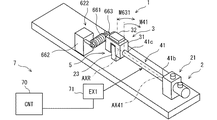
図1において、可動装置1は、固定の基台2と、基台2に対して機械的に動くことができる可動部3とを有する。可動部3は、高さ方向HDに沿って延びる回動軸AXRの周りを回転移動することができる。可動部3は、回動軸AXRの周りの所定の角度範囲RGを往復移動する。可動部3は、被駆動体31を有する。可動部3の動きは、揺動とも呼ばれる。なお、可動部3の移動方向は、回動に限られない。可動部3の移動方向は、例えば、高さ方向HDに沿う平行移動、幅方向WDに沿う平行移動、奥行き方向DDの周りにおける回転移動など多様な動きに適合可能である。
First Embodiment In FIG. 1, a
可動装置1は、被駆動体31に搭載された素子32を有する。素子32は、電気的な能動的作用、または電気的な受動的作用を提供する。素子32は、例えば、電気的な光源、電気的な送風機、電気的な熱源、電気的な電波源、電気的な磁力源である。素子32は、例えば、電気的なセンサ素子である。可動装置1は、電気的な接続のために、基台2と素子32とを電気的に接続する接続部材を備える場合がある。素子32は、主要な機能のための軸VR32を有する。軸VR32は、例えば、素子32が光源である場合には、光軸に相当する。軸VR32は、例えば、素子32がセンサである場合には、検出軸に相当する。軸VR32は、被駆動体31の回動によって振られる。軸VR32は、回動角VRSの範囲で振られる。
The
可動装置1は、センサ装置でもある。素子32は、センサ素子である。素子32は、検出方向と検出範囲を示す軸VR32を有する。素子32は、軸VR32の方向における物理量を検出する。素子32は、例えば、画像センサ、赤外線センサ、超音波センサ、レーダアンテナ、電磁波センサ、放射線センサなど多様な素子によって提供される。この実施形態では、素子32は、室内に設置される赤外線センサである。素子32の検出信号は、有線または無線によって赤外線情報を利用する機器に供給される。赤外線情報は、例えば、空調装置に供給され、利用される。可動装置1は、住居、事務所、車両、船舶、航空機などの室内に設置され、室内の人に関連する情報を収集するために利用される。基台2は、これらの室内に定置されている。
The
可動装置1は、軸VR32を振るように移動させる。可動装置1は、軸VR32を移動させるセンサ装置を提供する。軸VR32の移動は、指向方向可変型、追尾型、あるいは走査型といった多様なセンサ装置の提供を可能とする。この実施形態では、被駆動体31は、周期的に揺動するから、走査型のセンサ装置が提供されている。軸VR32は、回動軸AXRを中心に回動する。軸VR32は、幅方向WDと奥行き方向DDとに広がる平面に沿って、所定の回動角VRSの範囲内を移動可能である。この実施形態では、回動角VRSが走査範囲である。
The
可動装置1は、アクチュエータ機構4を備える。アクチュエータ機構4は、可動部3を回動させるための回転力を提供する。アクチュエータ機構4は、動力源でもある。アクチュエータ機構4は、往復するように回転力を提供する。
The
アクチュエータ機構4は、2つのアクチュエータ素子41、42を有する。2つのアクチュエータ素子41、42は、回動軸AXRの延長線上に配置されている。2つのアクチュエータ素子41、42は、被駆動体31の両側に配置されている。被駆動体31と、2つのアクチュエータ素子41、42とは、直列的に配置されている。図中では、アクチュエータ素子41、42は、やや太く強調されて図示されている。
The
第1のアクチュエータ素子41は、被駆動体31と、固定部21とに連結されている。第1のアクチュエータ素子41は、アクチュエータ軸AX41に沿って延びている。アクチュエータ軸AX41は、第1のアクチュエータ素子41の中心軸でもある。アクチュエータ軸AX41は、回動軸AXRの延長上に位置している。アクチュエータ軸AX41と回動軸AXRとは同軸である。
The
第2のアクチュエータ素子42は、被駆動体31と、固定部22とに連結されている。第2のアクチュエータ素子42は、アクチュエータ軸AX42に沿って延びている。アクチュエータ軸AX42は、第2のアクチュエータ素子42の中心軸でもある。アクチュエータ軸AX42は、回動軸AXRの延長上に位置している。アクチュエータ軸AX42と回動軸AXRとは同軸である。
The
被駆動体31は、基台2の中央部に配置されている。固定部21は、基台2の一端部に設けられている。固定部21は、基台2に固定されている。固定部22は、基台2の他端部に設けられている。固定部22は、基台2に固定されている。基台2は、アクチュエータ機構4が発生する力に対抗して、可動装置1の形状を維持できる材料で作られている。例えば、基台2は、金属製または樹脂製である。基台2の一部または全体は、プリント配線板によって提供されていてもよい。
The driven
第1のアクチュエータ素子41と、第2のアクチュエータ素子42とは、被駆動体31に対して対称的に配置されている。第1のアクチュエータ素子41と、第2のアクチュエータ素子42とは、対称的な構造を有する。以下の説明では、第1のアクチュエータ素子41について説明する。この説明は、第2のアクチュエータ素子42の説明として参照することができる。
The
第1のアクチュエータ素子41は、固定部21に連結されうる固定端41bを有する。固定端41bは、少なくとも第1のアクチュエータ素子41が回動力を出力するときに固定部21に連結されている。第1のアクチュエータ素子41は、被駆動体31に連結されうる出力端41cを有する。出力端41cは、少なくとも第1のアクチュエータ素子41が回動力を出力するときに被駆動体31に連結されている。被駆動体31は、アクチュエータ軸AX41上においてアクチュエータ素子41と連結されている。なお、固定端41bおよび出力端41cの名称は、便宜的なものである。以下の説明では、固定端41bおよび出力端41cは、単に端部と呼ばれることがある。
The
第1のアクチュエータ素子41は、棒状である。第1のアクチュエータ素子41は、細長い棒状または繊維状と呼べる形状である。第1のアクチュエータ素子41は、円柱状または円筒状に形成することができる。
The
可動装置1は、可動部3の動きを案内するための案内機構5を有する。案内機構5は、基台2に設けられた支持部23と、被駆動体31との間に設けられている。支持部23は、基台2に固定されている。案内機構5は、高さ方向HDの周りにおける被駆動体31の回転運動を許容する。案内機構5は、奥行き方向DDの周りにおける回転運動、および幅方向WDの周りにおける回転運動を抑制する。案内機構5は、被駆動体31の移動のうち、奥行き方向DDへの上下運動、および幅方向WDへの左右運動を抑制する。案内機構5は、高さ方向HDへの前後運動を抑制してもよい。案内機構5は、高さ方向HDへの前後運動を許容する場合がある。
The
高さ方向HDをロール軸、幅方向WDをピッチング軸、および奥行き方向DDをヨー軸と定義することができる。この場合、案内機構5は、被駆動体31のロール運動を許容する。案内機構5は、利用可能な範囲を超えるような過剰なロール運動を抑制してもよい。例えば、被駆動体31と支持部23との直接的な衝突、または弾性部材を介した間接的な衝突は、ロール運動範囲を制限する。案内機構5は、被駆動体31のヨーイング運動、およびピッチング運動を抑制する。また、案内機構5は、被駆動体31の上下運動、および左右運動を抑制する。案内機構5は、被駆動体31の前後運動を抑制してもよい。案内機構5は、被駆動体31の前後運動を許容する場合がある。
The height direction HD can be defined as the roll axis, the width direction WD as the pitching axis, and the depth direction DD as the yaw axis. In this case, the
可動装置1は、制御システム7を備える。制御システム7は、制御装置(CNT)70と、エネルギ増減装置(EX1、EX2)71、72を有する。エネルギ増減装置71、72は、2つのアクチュエータ素子41、42から機械的な運動を取り出すために、2つのアクチュエータ素子41、42のエネルギを増減させる装置である。2つのアクチュエータ素子41、42を回転させるように、エネルギ増減装置71、72は2つのアクチュエータ素子41、42のエネルギを増減させる。
The
制御装置は、少なくともひとつの演算処理装置(CPU)と、プログラムとデータとを記憶する記憶媒体としての少なくともひとつのメモリ装置とを有する。制御装置は、コンピュータによって読み取り可能な記憶媒体を備えるマイクロコンピュータによって提供される。記憶媒体は、コンピュータによって読み取り可能なプログラムを非一時的に格納する非遷移的実体的記憶媒体である。記憶媒体は、半導体メモリまたは磁気ディスクなどによって提供されうる。制御装置は、ひとつのコンピュータ、またはデータ通信装置によってリンクされた一組のコンピュータ資源によって提供されうる。プログラムは、制御装置によって実行されることによって、制御装置をこの明細書に記載される装置として機能させ、この明細書に記載される方法を実行するように制御装置を機能させる。 The control device has at least one arithmetic processing unit (CPU) and at least one memory device as a storage medium for storing programs and data. The control device is provided by a microcomputer including a computer-readable storage medium. The storage medium is a non-transitional tangible storage medium that stores a computer-readable program in a non-temporary manner. The storage medium can be provided by a semiconductor memory or a magnetic disk. The controller can be provided by a computer or a set of computer resources linked by a data communication device. The program is executed by the control device to cause the control device to function as the device described in this specification and to cause the control device to perform the method described in this specification.
制御システムは、制御装置に入力される情報を示す信号を供給する複数の信号源を入力装置として有する。制御システムは、制御装置が情報をメモリ装置に格納することにより、情報を取得する。制御システムは、制御装置によって挙動が制御される複数の制御対象物を出力装置として有する。制御システムは、メモリ装置に格納された情報を信号に変換して制御対象物に供給することにより制御対象物の挙動を制御する。例えば、制御装置は、外部から作動信号と、停止信号とを取得し、エネルギ増減装置71、72を間欠的に活性化することにより、可動装置1に揺動的に運動させる。
The control system includes a plurality of signal sources that supply signals indicating information input to the control device as input devices. The control system acquires information by the control device storing the information in the memory device. The control system has a plurality of control objects whose behavior is controlled by the control device as output devices. The control system controls the behavior of the control object by converting information stored in the memory device into a signal and supplying the signal to the control object. For example, the control device acquires an operation signal and a stop signal from the outside, and intermittently activates the energy increasing / decreasing
制御システムに含まれる制御装置と信号源と制御対象物とは、多様な要素を提供する。それらの要素の少なくとも一部は、機能を実行するためのブロックと呼ぶことができる。別の観点では、それらの要素の少なくとも一部は、構成として解釈されるモジュール、またはセクションと呼ぶことができる。さらに、制御システムに含まれる要素は、意図的な場合にのみ、その機能を実現する手段ともよぶことができる。 The control device, the signal source, and the control object included in the control system provide various elements. At least some of these elements can be referred to as blocks for performing functions. In another aspect, at least some of these elements can be referred to as modules or sections that are interpreted as configurations. Furthermore, the elements included in the control system can also be referred to as means for realizing the functions only when intentional.
制御システムが提供する手段および/または機能は、実体的なメモリ装置に記録されたソフトウェアおよびそれを実行するコンピュータ、ソフトウェアのみ、ハードウェアのみ、あるいはそれらの組合せによって提供することができる。例えば、制御装置がハードウェアである電子回路によって提供される場合、それは多数の論理回路を含むデジタル回路、またはアナログ回路によって提供することができる。 The means and / or functions provided by the control system can be provided by software recorded in a substantial memory device and a computer that executes the software, software only, hardware only, or a combination thereof. For example, if the controller is provided by an electronic circuit that is hardware, it can be provided by a digital circuit including a number of logic circuits, or an analog circuit.
2つのアクチュエータ素子41、42は、ひとつの方向へ向けて能動的な変形を生じる。2つのアクチュエータ素子41、42の変形方向は、逆方向、すなわち対称的な方向である。2つのアクチュエータ素子41、42の利用により、両方向、すなわち往復的な方向に向けて能動的な変形が得られる。
The two
アクチュエータ素子41、42は、熱エネルギの増減によってアクチュエータ軸AX41、AX42周りの変形を生じる。第1のアクチュエータ素子41は、第1のアクチュエータ素子41の温度が上昇すると、ねじれるように変形する。固定端41bが固定部21によって固定されているから、被駆動体31は、第1の方向である矢印M41の方向へ回動する。第2のアクチュエータ素子42は、第2のアクチュエータ素子42の温度が上昇すると、ねじれるように変形する。固定端42bが固定部22によって固定されているから、被駆動体31は、第2の方向である矢印M42の方向へ回動する。矢印M41の方向と矢印M42の方向とは、被駆動体31に対して対称的である。この結果、被駆動体31は、矢印M31で図示される角度範囲にわたって回動する。矢印M31は、軸VR32の回動角VRSに対応している。
The
この実施形態に利用可能なアクチュエータ素子41、42と、エネルギ増減装置71、72とは、特開2016−42783号公報に記載のものを含む。特開2016−42783号公報の記載内容は、この明細書における技術的要素の説明として、参照により援用される。アクチュエータ素子41、42は、人工筋肉と呼ばれる多様な材料によって提供することができる。例えば、合成樹脂、金属、形状記憶合金、および有機物といった材料を利用可能である。
アクチュエータ素子41、42のひとつの例は、合成繊維である。合成繊維は、回動軸AXRの延長線上に沿って延びている。合成繊維は、細長い。合成繊維は、ポリマ繊維と呼ばれる。ポリマ繊維の典型的なひとつの例は、モノフィラメント樹脂である。モノフィラメント樹脂は、ポリアミド系樹脂、およびポリエチレン系樹脂を含む。例えば、ナイロン、またはポリチレンと呼ばれるポリマ繊維は、温度変化に対するねじり変形量を有する場合があり、アクチュエータ素子41、42として利用可能である。
One example of the
ポリマ繊維を形成する高分子は、アクチュエータ軸AX41、AX42に沿って延びるように配向されている。高分子は、アクチュエータ軸AX41、AX42の周りに「撚り」を有する場合がある。「撚り」の語は、単繊維の中における撚りを指す場合と、複数繊維の間における撚りを指す場合とがある。ポリマ繊維の温度変化に対するねじり変形量は、単繊維の中における「撚り」の方向に沿って強く表れる場合がある。この実施形態では、アクチュエータ素子41、42は、単繊維である。別の形態では、ポリマ繊維の温度変化に対するねじり変形量は、複数繊維の間における「撚り」の方向に沿って表れる場合がある。アクチュエータ素子41、42は、互いに撚られた複数のポリマ繊維の束でもよい。
The polymers forming the polymer fibers are oriented so as to extend along the actuator axes AX41 and AX42. The polymer may have a “twist” around the actuator axes AX41, AX42. The term “twist” may refer to a twist in a single fiber and may refer to a twist between multiple fibers. The twist deformation amount with respect to the temperature change of the polymer fiber may appear strongly along the direction of “twist” in the single fiber. In this embodiment, the
アクチュエータ素子41、42のひとつの例は、形状記憶合金である。アクチュエータ軸AX41、AX42に沿って延びる形状記憶合金を利用可能である。形状記憶合金は、単一の棒状、およびコイル状に巻かれた形状など多様な形状によって利用可能である。形状記憶合金の形状は、温度変化に対するねじり変形量を得られるように選択される。
One example of the
エネルギ増減装置71、72は、アクチュエータ素子41、42のエネルギ状態を高エネルギ状態と低エネルギ状態との間で双方向に変化させる。エネルギ増減装置71、72は、電気的に、光学的に、磁気的に、電磁波的に、あるいは放射線的にエネルギを付与し、除去することができる。電気的なエネルギの付与と除去とは、電気的な熱の増減、電流の増減、電界の増減、あるいは電荷の増減などを含む。例えば、アクチュエータ素子41、42のエネルギ状態が温度で示される場合、光の付与によって温度を増加させ、光の遮断によって温度を低下させることができる。
The energy increasing / decreasing
エネルギの付与と、除去とは、直接的に、または間接的に行うことができる。例えば、アクチュエータ素子41、42に直接的に接触するエネルギ伝達部品によってエネルギを付与してもよいし、またはアクチュエータ素子41、42から離れて設置されたエネルギ伝達部品によって間接的にエネルギを付与してもよい。エネルギ伝達部品は、例えば、電気的な発熱部材によって提供できる。
Energy can be applied and removed directly or indirectly. For example, energy may be applied by an energy transmission component that directly contacts the
例えば、アクチュエータ素子41、42を能動的に回転させるために、エネルギ増減装置71、72は、アクチュエータ素子41、42の熱エネルギを増加させる。熱エネルギの増加は、例えば、アクチュエータ素子41、42が備える発熱部材への電流供給を行うことによって実現される。例えば、アクチュエータ素子41、42を能動的な回転から復帰させるために、エネルギ増減装置71、72は、アクチュエータ素子41、42の熱エネルギを減少させる。熱エネルギの減少は、例えば、アクチュエータ素子41、42が備える発熱部材への電流供給を遮断し、放熱させることによって実現される。
For example, the energy increasing / decreasing
図2において、固定部21と、固定部22とは、被駆動体31に対して対称的に配置されている。固定部21と、固定部22とは、対称的な構造を有する。被駆動体31は、案内機構5に対して対称的な構造を有する。以下の説明では、第1のアクチュエータ素子41に関連する部分について説明する。この説明は、第2のアクチュエータ素子42に関連する部分の説明として参照することができる。第1のアクチュエータ素子41に関連する部分として、固定部21と、被駆動体31に設けられた第3連結機構31cとがある。
In FIG. 2, the fixed
固定部21は、エンドスリーブ21aと、アンカブロック21cとを有する。エンドスリーブ21aは、アクチュエータ素子41の端部に連結されている。エンドスリーブ21aは、アンカブロック21cに固定されている。アンカブロック21cは、基台2に固定されている。
The fixing
エンドスリーブ21aは、アクチュエータ素子41と同軸の円筒状部材である。エンドスリーブ21aは、多角形の角筒状でもよい。エンドスリーブ21aは、アクチュエータ素子41の固定端41bを受け入れる内穴を有する。エンドスリーブ21aは、固定端41bとエンドスリーブ21aとを連結する第1連結機構21bを有する。第1連結機構21bは、固定端41bと、エンドスリーブ21aとを、少なくともアクチュエータ素子41が回動力を出力するときにアクチュエータ軸AX41の周方向に関して連結する。
The
第1連結機構21bは、内穴とセットスクリュとによって提供されている。セットスクリュは、エンドスリーブ21aの内穴に向けて径方向に設けられている。セットスクリュは、固定端41bを径方向に締め付けることにより、固定端41bと、エンドスリーブ21aとを、軸方向および周方向に関して連結している。
The first connecting
第1連結機構21bは、多様な機構によって提供することができる。例えば、第1連結機構21bは、放射状に配置された複数のセットスクリュ、固定端41bを径方向に締め付けるチャック機構、固定端41bを径方向に締め付けるかしめスリーブなどによって提供することができる。第1連結機構21bは、アクチュエータ軸AX41に沿って、エンドスリーブ21aに対する固定端41bの軸方向移動を許容してもよい。例えば、固定端41bが制限された範囲内において、軸方向に移動できるように、固定端41bと、エンドスリーブ21aとを連結してもよい。例えば、スプリングまたはゴムのような弾性部材を用いることができる。第1連結機構21bは、開閉可能な機構によって提供されてもよい。例えば、第1連結機構21bは、固定端41bを周方向に固定している状態と、固定端41bを周方向に回動可能としている状態とを切替可能な電磁的機構により提供することができる。
The
アンカブロック21cは、エンドスリーブ21aを受け入れる内穴を有する。アンカブロック21cは、エンドスリーブ21aとアンカブロック21cとを連結する第2連結機構21dを有する。第2連結機構21dは、エンドスリーブ21aとアンカブロック21cとを、少なくともアクチュエータ素子41が回動力を出力するときにアクチュエータ軸AX41の周方向に関して連結する。
The anchor block 21c has an inner hole for receiving the
第2連結機構21dは、内穴とセットスクリュとによって提供されている。セットスクリュは、アンカブロック21cの内穴に向けて径方向に設けられている。セットスクリュは、エンドスリーブ21aを径方向に締め付けることにより、エンドスリーブ21aとアンカブロック21cとを、軸方向および周方向に関して連結している。
The second connecting mechanism 21d is provided by an inner hole and a set screw. The set screw is provided in the radial direction toward the inner hole of the anchor block 21c. The set screw couples the
第2連結機構21dは、多様な機構によって提供することができる。例えば、第2連結機構21dは、放射状に配置された複数のセットスクリュ、エンドスリーブ21aを径方向に締め付けるチャック機構、エンドスリーブ21aを径方向に締め付けるかしめスリーブなどによって提供することができる。第2連結機構21dは、アクチュエータ軸AX41に沿って、エンドスリーブ21aの軸方向移動を許容してもよい。例えば、エンドスリーブ21aが制限された範囲内において、軸方向に移動できるように、アンカブロック21cと、エンドスリーブ21aとを連結してもよい。例えば、スプリングまたはゴムのような弾性部材を用いることができる。第2連結機構21dは、開閉可能な機構によって提供されてもよい。例えば、第2連結機構21dは、アクチュエータ素子41の端部を周方向に固定している状態と、アクチュエータ素子41の端部を周方向に回動可能としている状態とを切替可能な電磁的機構により提供することができる。
The second coupling mechanism 21d can be provided by various mechanisms. For example, the second connecting mechanism 21d can be provided by a plurality of set screws arranged radially, a chuck mechanism that tightens the
被駆動体31は、アクチュエータ素子41の出力端41cを受け入れる内穴を有する。被駆動体31は、被駆動体31と出力端41cとを連結する第3連結機構31aを有する。第3連結機構31aは、出力端41cと被駆動体31とを、少なくともアクチュエータ素子41が回動力を出力するときにアクチュエータ軸AX41の周方向に関して連結する。
The driven
第3連結機構31aは、内穴とセットスクリュとによって提供されている。セットスクリュは、被駆動体31の内穴に向けて径方向に設けられている。セットスクリュは、出力端41cを径方向に締め付けることにより、被駆動体31と出力端41cとを、軸方向および周方向に関して連結している。
The
第3連結機構31aは、多様な機構によって提供することができる。例えば、第3連結機構31aは、放射状に配置された複数のセットスクリュ、出力端41cを径方向に締め付けるチャック機構、出力端41cを径方向に締め付けるかしめスリーブなどによって提供することができる。第3連結機構31aは、アクチュエータ軸AX41に沿って、被駆動体31に対する出力端41cの軸方向移動を許容してもよい。例えば、出力端41cが制限された範囲内において、軸方向に移動できるように、出力端41cと、被駆動体31とを連結してもよい。例えば、スプリングまたはゴムのような弾性部材を用いることができる。第3連結機構31aは、開閉可能な機構によって提供されてもよい。例えば、第3連結機構31aは、出力端41cを周方向に固定している状態と、出力端41cを周方向に回動可能としている状態とを切替可能な電磁的機構により提供することができる。
The
被駆動体31は、案内機構5によって回動可能に支持されている。案内機構5は、シャフト51とガイドボア52とを有する。シャフト51は、回動軸AXRの同軸の円筒状部材によって提供されている。シャフト51は、被駆動体31に固定されている。シャフト51の両端が、被駆動体31に固定されている。被駆動体31は、シャフト51を有する。ガイドボア52は、支持部23に設けられている。支持部23は、ガイドボア52を有する。支持部23は、被駆動体31を支持するための部材である。支持部23は、基台2に固定されている。支持部23は、ブロックである。ガイドボア52は、支持部23を貫通する貫通穴によって提供されている。ガイドボア52は、シャフト51を受け入れている。ガイドボア52は、シャフト51の回転を許容する。この結果、支持部23は、被駆動体31を回転可能に支持している。
The driven
シャフト51の外面と、ガイドボア52の内面とは、部分的に接触している。シャフト51の外面と、ガイドボア52の内面とは、被駆動体31が回動すると、互いに摺動する。被駆動体31は、シャフト51の周りにおいて案内されている。シャフト51およびガイドボア52を提供する部材は、低摩擦材料製である。シャフト51、またはガイドボア52を提供する部材を、低摩擦材料製としてもよい。シャフト51とガイドボア52との間の摩擦が抑制される。
The outer surface of the
支持部23は、その両端面において、被駆動体31と対向している。支持部23は、その両端面において、部分的に被駆動体31と接触している。支持部23と被駆動体31とは、被駆動体31が回動すると、互いに摺動する。
The
アクチュエータ素子41の熱は、アクチュエータ素子41の全体から、外部環境へ放熱される。アクチュエータ素子41の熱は、固定端41bから、固定部21を経由して放熱される。このとき、第1連結機構21b、および第2連結機構21dは、放熱経路の熱的な抵抗を下げるために貢献する。さらに、アクチュエータ素子41の熱は、出力端41cから、被駆動体31を経由して放熱される。アクチュエータ素子41の熱は、出力端41cから、被駆動体31、支持部23、および基台2を経由して放熱される場合がある。このとき、第3連結機構31aは、放熱経路の熱的な抵抗を下げるために貢献する。
The heat of the
さらに、被駆動体31と支持部23との間の接触、および/またはシャフト51とガイドボア52との間の接触も、放熱経路の熱的な抵抗を下げるために貢献する。アクチュエータ素子41の熱は、出力端41cから、被駆動体31、被駆動体31と支持部23との間の接触、および支持部23を経由して放熱される。また、アクチュエータ素子41の熱は、出力端41cから、被駆動体31を通り、シャフト51、シャフト51とガイドボア52との間の接触、および支持部23を経由して放熱される。このように、アクチュエータ素子41は、被駆動体31および案内機構5を経由して放熱する。
Furthermore, the contact between the driven
図3において、アクチュエータ素子41は、素材線41a、固定端41b、出力端41c、および発熱線41dを有する。素材線41aは、上述のポリマ繊維である。発熱線41dは、エネルギ増減装置71の一部でもある。発熱線41dは、素材線41aのエネルギを増減させるためのエネルギ伝達部品でもある。発熱線41dは、素材線41aの表面上において、直接的に、または間接的に配置されている。発熱線41dは、螺旋状、またはコイル状である。発熱線41dは、通電によって発熱する金属線である。発熱線41dは、白金線、銅線などによって提供できる。発熱線41dは、ニクロム線によって提供されている。発熱線41dは、丸線、角線、または金属箔によって提供することができる。発熱線41dは、素材線41aの表面に貼り付けられている。
In FIG. 3, the
発熱線41dは、正電極41pと、負電極41nとを有する。正電極41pと、負電極41nとは、ほぼ発熱しない電線である。正電極41pと負電極41nとは、接続部41mに配置されている。接続部41mは、アクチュエータ素子41の2つの端部のうち、一方の端部に配置されている。接続部41mは、固定端41bの近傍に配置されている。発熱線41dは、接続部41mにおいて通常の電線、回路基板、フレキシブル回路基板などと接続される。正電極41pと負電極41nとの両方を接続部41mに配置する構成は、電気的な接続のための構成を簡単にする。
The
発熱線41dは、戻り部41rを有する。戻り部41rは、アクチュエータ素子41の2つの端部のうち、他方の端部に配置されている。戻り部41rは、出力端41cの近傍に配置されている。発熱線41dは、接続部41mから始まり、接続部41mに戻るような「ひとふで書き」形状に形成されている。この実施形態では、発熱線41dは、2本の螺旋を有する往復状に形成されている。発熱線41dは、正電極41pから戻り部41rに到達する往路部を有する。発熱線41dは、戻り部41rから負電極41nに到達する復路部を有する。往路部と、復路部とは、平行に配置されている。発熱線41dは、ヘアピン状に曲げられたニクロム線を、素材線41aに巻き付けることによって螺旋状に形成されている。
The
発熱線41dは、通電されると、発熱する。発熱線41dにより供給される熱は、素材線41aに伝わり、素材線41aの温度を上昇させる。一方で、発熱線41dは、通電が遮断されると、発熱を停止する。素材線41aの熱は、外部環境へ放熱される。このとき、出力端41cにおける第3連結機構31aと、案内機構5とが放熱に貢献する。このため、アクチュエータ素子41において大きい温度差を実現することができる。
The
図4において、被駆動体31を揺動運動させるための制御処理180が図示されている。制御処理180は、制御装置70における制御処理の一部である。
In FIG. 4, a
ステップ181では、可動装置1の揺動が求められている(ON)か、否(OFF)かを判定する。例えば、走査型の赤外線センサを作動させることが求められている場合、揺動ONとなる。走査型の赤外線センサを作動させることが求められていない場合、揺動OFFとなる。揺動OFFの場合、制御を終了する。揺動ONの場合、ステップ182とステップ183とによるループ処理へ進む。ステップ182は、第1のアクチュエータ素子41を加熱するための処理である。ステップ183は、第2のアクチュエータ素子42を加熱するための処理である。ステップ182とステップ183とを交互に繰り返すことにより、被駆動体31は揺動的に動作する。ステップ184では、可動装置1の揺動が求められている(ON)か、否(OFF)かを判定する。
In
ステップ182は、被駆動体31を正転方向へ回転させる処理である。正転方向は、第1のアクチュエータ素子41から見て、被駆動体31を時計回り方向に回転させる方向である。ステップ182は、ステップ185と、ステップ186とを有する。
Step 182 is a process of rotating the driven
ステップ185では、まず、第1のアクチュエータ素子41を活性化させる。ステップ185では、第1のアクチュエータ素子41の発熱線41dに通電する。具体的には、制御装置70は、エネルギ増減装置71から発熱線41dに通電する。ステップ185の処理は、第1のアクチュエータ素子41が正転方向へ所定角度のねじりを出力するように実行される。例えば、回転角センサによって被駆動体31の回転角度を検出し、所定角度の回動が得られるまで、ステップ185が継続される。これに代えて、タイマ処理によって、ステップ185の処理を一定時間継続してもよい。
In
ステップ186では、第1のアクチュエータ素子41を不活性化させる。ステップ186では、第1のアクチュエータ素子41の発熱線41dへの通電を遮断する。具体的には、制御装置70は、エネルギ増減装置71から発熱線41dへの通電を遮断する。
In
ステップ183は、被駆動体31を逆転方向へ回転させる処理である。ステップ183は、ステップ187と、ステップ188とを有する。
Step 183 is a process of rotating the driven
ステップ187では、まず、第2のアクチュエータ素子42を活性化させる。ステップ187では、第2のアクチュエータ素子42の発熱線に通電する。具体的には、制御装置70は、エネルギ増減装置72から発熱線に通電する。
In
ステップ188では、第2のアクチュエータ素子42を不活性化させる。ステップ188では、第2のアクチュエータ素子42の発熱線への通電を遮断する。具体的には、制御装置70は、エネルギ増減装置72から発熱線への通電を遮断する。
In
この実施形態では、活性化は、発熱線41dへの通電に対応する。不活性化は、発熱線41dへの通電の遮断に対応する。活性化と不活性化との語の対は、加熱と放熱との語の対に、付勢と消勢との語の対に、アクティブとスタンバイとの語の対に対応付けることができる。
In this embodiment, the activation corresponds to energization of the
制御装置70は、アクチュエータ素子41のエネルギが増加する期間と、アクチュエータ素子41のエネルギが減少する期間とを交互に繰り返すようにエネルギ増減装置71を制御する。この結果、2つのアクチュエータ素子41、42が交互に能動的に駆動される。第1のアクチュエータ素子41が能動的に正転方向のねじり変形を出力しているときに、第2のアクチュエータ素子42は受動的に正転方向へ駆動される。逆に、第2のアクチュエータ素子42が能動的に逆転方向のねじり変形を出力しているときに、第1のアクチュエータ素子41は受動的に逆転方向へ駆動される。2つのアクチュエータ素子41、42が使用され、それらが交互に駆動されるから、両方向に関して安定的な回動出力が得られる。
The
以上に述べたこの実施形態によると、静かな可動装置1を提供することができる。特に、可動装置1が室内に設置される装置に利用される場合に有利である。例えば、静かな、走査型の赤外線センサが得られる。可動装置1は、案内機構5を備えるから、被駆動体31の振動が抑制される。特に、回動軸AXRに交差する方向、すなわち回動軸AXRに対する上下方向、および左右方向の振動が抑制される。案内機構5は、アクチュエータ軸AX41と同軸の回動軸AXRを規定するから、アクチュエータ素子41のねじり変形を直接的に取り出すことができる。さらに、案内機構5は、アクチュエータ素子41の放熱に貢献する。
According to this embodiment described above, the quiet
図5において、アクチュエータ素子41がモデル化して図示されている。発熱線41dは、アクチュエータ軸AX41に沿って往復状に形成されている。発熱線41dは、アクチュエータ軸AX41の長手方向に関して往復状である。発熱線41dは、アクチュエータ軸AX41の周りに関して往復状である。
In FIG. 5, the
アクチュエータ素子41は、アクチュエータ軸AX41の一端であって、固定されている固定端41bを有する。アクチュエータ素子41は、アクチュエータ軸AX41の他端であって、被駆動体31に連結されており、ねじり変形を出力するための出力端41cを有している。
The
接続部41mは、固定端41bの近傍に配置されている。接続部41mは、アクチュエータ軸AX41の長手方向の中央よりも固定端41bの側に配置されている。接続部41mは、アクチュエータ軸AX41の長手方向の中央より固定端41bの近くに配置されている。固定端41bにおける変形量は小さい。このため、接続部41mにおける機械的変位を抑制することができる。固定端41bの近傍に配置された接続部は、電気的な接続の劣化を抑制するために貢献する。
The
戻り部41rは、エネルギ伝達部品を往復状に配置するための部分である。戻り部41rは、ターン部とも呼ぶことができる。戻り部41rは、アクチュエータ軸AX41の長手方向の中央より出力端41cの側に配置されている。発熱線41dは、複数の往復状に形成されてもよい。例えば、偶数の往路部、偶数の復路部が設けられる。この場合、出力端41cの近傍には、偶数の戻り部41rが配置される。さらに、固定端41bの近傍にも奇数の戻り部41rが配置される。
The
基台2の上には、エネルギ増減装置71が配置されている。発熱線41dは、接続部41mにおいて、エネルギ増減装置71と電気的に接続されている。言い換えると、発熱線41dは、接続部41mにおいて、基台2と電気的に接続されている。正電極41pと負電極41nとの両方は、細長いアクチュエータ素子41の上の狭い一箇所、すなわち接続部41mから取り出されている。エネルギ伝達部品の両方の端部41p、41nが、アクチュエータ素子41の端部に設けられた接続部41mに集められている。これにより、電気的な接続に必要な部品を集中的に配置することができる。
An energy increasing / decreasing
この実施形態によると、エネルギ伝達部品が改良された可動装置が提供される。ひとつの観点において、往復状に配置された発熱線41dは、アクチュエータ素子の広い範囲にわたって、発熱線41dから素材線41aへエネルギを伝達することができる。別の観点では、接続部41mに集中的に配置された正電極41pと負電極41nとは、アクチュエータ素子41が変形しても、同じ挙動を示す。このため、正電極41pの挙動と負電極41nの挙動との差に起因する電気的な接続の劣化が抑制される。
According to this embodiment, a mobile device with improved energy transfer components is provided. In one viewpoint, the
さらに、接続部41mは、細長いアクチュエータ素子41のうち、アクチュエータ軸AX41の方向の中央よりも固定端41bの近くに設けられている。接続部41mは、固定端41bの近傍に設けられている。この構成は、アクチュエータ素子41が変形しても、正電極41pと負電極41nとの変位を抑制する。よって、さらに別の観点では、安定的な電気的接続を有する可動装置が提供される。
Further, the
第2実施形態
この実施形態は、先行する実施形態を基礎的形態とする変形例である。上記実施形態では、正電極41pと負電極41nとの両方が、接続部41mにおいて、エネルギ増減装置71に直接に接続されている。これに代えて、この実施形態では、正電極241pと負電極241nとの両方が、固定部21によって支持されている。
Second Embodiment This embodiment is a modified example based on the preceding embodiment. In the said embodiment, both the positive electrode 41p and the negative electrode 41n are directly connected to the energy increase /
図6に図示されるように、固定部21は、正電極241pと負電極41nとを支持している。正電極241pと負電極41nとは、固定部21の中を通るように配置されるか、固定部21の表面に沿って配置されている。正電極241pと負電極41nとは、接続部41mの近傍において固定部21から離れ、素材線41aに向けて延びている。正電極241pと負電極41nとは、基台2の近傍において固定部21から離れ、エネルギ増減装置71に向けて延びている。この実施形態によると、正電極241pと負電極41nとが安定的に支持される。この構成は、電気的な接続を安定化するために貢献する。
As illustrated in FIG. 6, the fixing
第3実施形態
この実施形態は、先行する実施形態を基礎的形態とする変形例である。上記実施形態では、発熱部材は、ニクロム線によって提供されている。これに代えて、発熱部材は、多様な電気的な発熱部材によって提供できる。この実施形態では、発熱部材は、導電性薄膜341dによって形成されている。
Third Embodiment This embodiment is a modification in which the preceding embodiment is a basic form. In the said embodiment, the heat generating member is provided with the nichrome wire. Instead, the heat generating member can be provided by various electric heat generating members. In this embodiment, the heat generating member is formed of a conductive
図7に図示されるように、導電性薄膜341dは、素材線41aの外表面に配置されている。導電性薄膜341dは、導電性高分子または導電性金属皮膜と呼ばれる膜によって提供されてもよい。この場合、膜は、素材線41aの表面に形成される。例えば、導電性高分子または導電性金属皮膜は、素材線41aの表面にメッキ、合成、スパッタなど多様な手法によって形成される。その形状は素材線41aの周囲に巻き付いている螺旋状である。また、素材線41aとは別に形成された、リボン状の導電性高分子または導電性金属皮膜を巻くことによって、螺旋状のエネルギ伝達部材を形成し、素材線41aの外表面に配置してもよい。
As shown in FIG. 7, the conductive
第4実施形態
この実施形態は、先行する実施形態を基礎的形態とする変形例である。上記実施形態では、螺旋状の発熱線41dが採用されている。これに代えて、この実施形態では、直線状の発熱線441dが用いられている。
Fourth Embodiment This embodiment is a modified example based on the preceding embodiment. In the above embodiment, the
図8に図示されるように、エネルギ伝達部品は、発熱線441dによって提供されている。発熱線441dは、主としてアクチュエータ軸AX41に沿って直線状に延びている。発熱線441dは、戻り部41rを有する。発熱線441dは、戻り部41rにおいてターンする往復状に形成されている。発熱線441dは、互いに平行な少なくとも2つの直線部と、それら直線部を出力端41cにおいて接続する戻り部41rとを有する。アクチュエータ素子41は、複数の発熱線441dを有する。複数の発熱線441dは、正電極241pと負電極241nとの間において、並列に接続されている。この実施形態では、アクチュエータ素子41は、2つの発熱線441d、441dを有する。素材線41aの外表面には、4本の直線部が等角度間隔で配置されている。
As shown in FIG. 8, the energy transfer component is provided by a
さらに多くの直線部が配置されていてもよい。また、発熱線441dは、往復状に制限されるものではなく、複数の往復部を有していてもよい。この実施形態でも、電気的な接続の安定性が改善される。
Further, many straight portions may be arranged. The
第5実施形態
この実施形態は、先行する実施形態を基礎的形態とする変形例である。直線状の形状は、導電性薄膜541dでも採用することができる。
Fifth Embodiment This embodiment is a modified example based on the preceding embodiment. A linear shape can also be employed for the conductive
図9において、導電性薄膜541dは、先行する実施形態と同様に、導電性高分子または導電性金属皮膜と呼ばれる膜によって提供される。この実施形態でも、先行する実施形態と同様の作用効果が得られる。
In FIG. 9, the conductive
第6実施形態
この実施形態は、先行する実施形態を基礎的形態とする変形例である。上記実施形態では、2つのアクチュエータ素子41、42が利用されている。これに代えて、ひとつのアクチュエータ素子41だけを備えてもよい。この場合、第2のアクチュエータ素子42に代えて、受動的な回動機構を用いることができる。受動的な回動機構は、ゴム、樹脂製バネ、金属製バネ、空気バネなど多様な機構により提供することができる。受動的な回動機構は、戻し機構と呼ばれる。
Sixth Embodiment This embodiment is a modification in which the preceding embodiment is a basic form. In the above embodiment, two
図10において、可動装置1は、第2のアクチュエータ素子42に代えて、戻し機構622を有する。戻し機構622は、受動的な弾性部材661と、固定部662と、固定部663とを有する。固定部662は、基台2に固定されたブロックである。固定部663は、被駆動体31に固定されている。
In FIG. 10, the
弾性部材661は、金属製のコイルバネである。弾性部材661は、自由状態よりも引っ張られることにより、被駆動体31に反時計周り方向の力を作用させる。弾性部材661は、被駆動体31の回動範囲M631の一端を基準位置とする。弾性部材661は、アクチュエータ素子41のねじり運動によって引っ張られるように配置されている。弾性部材661は、矢印M41の方向への回動力に抗して、戻し力を作用させる。この結果、アクチュエータ素子41が間欠的に駆動されることにより、言い換えると、周期的に活性化状態と不活性化状態とを繰り返すことにより、被駆動体31は、回動範囲M631において、回動運動する。
The
この実施形態によると、ひとつのアクチュエータ素子41によって往復的な被駆動体31の動きを得ることができる。しかも、案内機構5を備えるから、被駆動体31が安定する。この実施形態の構成は、先行する他の実施形態においても利用可能である。
According to this embodiment, the reciprocating motion of the driven
第7実施形態
この実施形態は、先行する実施形態を基礎的形態とする変形例である。上記実施形態では、エネルギ伝達部品は、素材線41aに直接的に接触し、素材線41aに直接的にエネルギを伝達する。これに代えて、この実施形態では、エネルギ伝達部品は、素材線41aに間接的にエネルギを伝達する。
Seventh Embodiment This embodiment is a modified example based on the preceding embodiment. In the embodiment, the energy transmission component directly contacts the
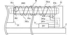
図11において、素材線41aと、発熱線741dとの間には、筒状の部材であるボビン741sが配置されている。ボビン741sは、優れた熱伝導性を有している。ボビン741sは、電気絶縁性である。例えば、ボビン741sは、ガラス管によって提供される。例えば、ボビン741sは、網の目状の壁をもつ樹脂製の筒状部材によって提供されてもよい。
In FIG. 11, a
ボビン741sは、固定部21によって支持されている。ボビン741sは、基台2に固定されていてもよい。この場合、素材線41aのねじり変形は、接続部41mに影響を与えない。よって、ボビン741sは、機械的な変形を絶縁する部材でもある。
The
アクチュエータ素子41の製造方法において、発熱線741dは、ボビン741sに巻き付けられる。発熱線741dは、ボビン741sの外表面に接触している。発熱線741sは、ボビン741sによって保持されている。発熱線741dが螺旋状に巻き付けられたボビン741sは、素材線41aの径方向外側に配置される。よって、発熱線741dは、素材線41aの径方向外側に螺旋状に配置される。
In the method for manufacturing the
この実施形態によると、ボビン741sによって素材線41aのねじり変形と、接続部41mとが完全に分離される。このため、接続部41mにおける電気的な接続の安定性が改善される。
According to this embodiment, the torsional deformation of the
第8実施形態
この実施形態は、先行する実施形態を基礎的形態とする変形例である。この実施形態では、直線状の発熱線841dが用いられている。
Eighth Embodiment This embodiment is a modification example based on the preceding embodiment. In this embodiment, a
図12に図示されるように、螺旋状の発熱線741dに代えて、直線状の発熱線841dを用いることができる。発熱線841dは、ボビン741sの外表面に配置されている。この実施形態でも、電気的な接続の安定性が改善される。なお、第7実施形態および第8実施形態においても、発熱線に代えて、導電性薄膜を用いることができる。
As shown in FIG. 12, a
他の実施形態
この明細書における開示は、例示された実施形態に制限されない。開示は、例示された実施形態と、それらに基づく当業者による変形態様を包含する。例えば、開示は、実施形態において示された部品および/または要素の組み合わせに限定されない。開示は、多様な組み合わせによって実施可能である。開示は、実施形態に追加可能な追加的な部分をもつことができる。開示は、実施形態の部品および/または要素が省略されたものを包含する。開示は、ひとつの実施形態と他の実施形態との間における部品および/または要素の置き換え、または組み合わせを包含する。開示される技術的範囲は、実施形態の記載に限定されない。開示されるいくつかの技術的範囲は、請求の範囲の記載によって示され、さらに請求の範囲の記載と均等の意味及び範囲内での全ての変更を含むものと解されるべきである。
Other Embodiments The disclosure herein is not limited to the illustrated embodiments. The disclosure encompasses the illustrated embodiments and variations by those skilled in the art based thereon. For example, the disclosure is not limited to the combinations of parts and / or elements shown in the embodiments. The disclosure can be implemented in various combinations. The disclosure may have additional parts that can be added to the embodiments. The disclosure includes those in which parts and / or elements of the embodiments are omitted. The disclosure encompasses the replacement or combination of parts and / or elements between one embodiment and another. The technical scope disclosed is not limited to the description of the embodiments. The several technical scopes disclosed are indicated by the description of the claims, and should be understood to include all modifications within the meaning and scope equivalent to the description of the claims.
先行する複数の実施形態では、シャフト51と、ガイドボア52とによって案内機構5を提供した。シャフト51と、ガイドボア52とは、いわゆる軸受機構を提供している。案内機構5を提供する軸受機構は、実施形態のような摺動軸受の他に、ボールベアリング、流体軸受、および磁力軸受など多くの機構によって提供可能である。この実施形態では、アクチュエータ素子41、42によって出力可能な回転トルクの上限に配慮して、比較的簡単で軽量な摺動軸受を採用している。
In the plurality of preceding embodiments, the
先行する複数の実施形態では、別体のシャフト51を、被駆動体31に固定した。これに代えて、被駆動体31または支持部23にシャフトを一体的に形成してもよい。例えば、シャフト51に代わる円柱部分を、被駆動体31または支持部23に機械加工によって形成することができる。また、シャフト51に代わる円柱部分を、被駆動体31または支持部23にインサート成形してもよい。
In the plurality of preceding embodiments, the
先行する複数の実施形態では、可動装置1は、案内機構5を備える。これに代えて、案内機構5を設けることなく、アクチュエータ素子41、42と接続部材とによって被駆動体31を支持してもよい。巻き形状の接続部材は、被駆動体31の安定的な回動を可能とする。先行する複数の実施形態では、案内機構5は、シャフト51とガイドボア52とを備える。これに代えて、振り子のように被駆動体を吊るす案内機構、または倒立振り子のように支点で被駆動体を支える案内機構を採用してもよい。
In a plurality of preceding embodiments, the
先行する実施形態に加えて、固定部は、機械的に回転方向を制限する機構を備えることができる。例えば、固定部には、ラチェット機構を設けることができる。ラチェット機構は、例えば、固定端41bが矢印M42の方向へ回転する場合には、固定端41bを固定する。逆に、固定端41bに矢印M41の方向へ回転する場合には、固定端41bを開放する。ラチェット機構は、能動的な変形を許容するように固定状態となり、受動的な変形を無効化するように開放状態となる。
In addition to the preceding embodiment, the fixing portion may include a mechanism that mechanically limits the rotation direction. For example, a ratchet mechanism can be provided in the fixing portion. For example, when the
先行する実施形態に加えて、固定端41bまたは出力端41cにおける固定力を可変としてもよい。この場合、電気的に固定力を可変に制御可能な固定部を設けてもよい。固定部21、22による固定力は、開放状態と固定状態とに、または強弱に変更されてもよい。例えば、連結機構21dは、エンドスリーブ21aの外周面に強く締め付けられた状態と、エンドスリーブ21aの外周面に弱く押し当てられた状態とに切り換えられてもよい。この場合、エンドスリーブ21aは、セットスクリュと摩擦しながら回転する。
In addition to the preceding embodiment, the fixing force at the
先行する実施形態では、素材線41aに発熱線41dを直接的に巻き付けている。これに代えて、素材線41aと発熱線41dとの間に部材を配置してもよい。例えば、電気絶縁性であって、優れた熱伝導性をもつ支持部材を配置することができる。支持部材は、素材線41aに巻き付けられる絶縁紙、または素材線41aを内部に収容するガラス筒によって提供することができる。このように、ひとつの態様では、発熱線41dは素材線41aに直接的に接触しているが、他の態様では、発熱線41dは素材線41aに直接的に接触することなく、巻き付けられた形状を有する。支持部材の内面に発熱部材を配置してもよい。
In the preceding embodiment, the
先行する実施形態では、アクチュエータ素子41は、ボビン741sを備える。これに代えて、ボビン741sなしで、エネルギ伝達部品を往復状として支持することができる。例えば、発熱線741d自身を固定部21に固定してもよい。また、ボビン741sの内面に発熱線741dを配置してもよい。
In the preceding embodiment, the
先行する実施形態では、発熱線41dによる加熱と、放熱とによって、素材線41aのエネルギの増減を実現している。これに代えて、冷却装置による冷却と、放冷とによって、素材線41aのエネルギの増減を実現することができる。例えば、ペルチェ効果素子を素材線41aに沿って配置することができる。ペルチェ効果素子は、エネルギ伝達部品を提供する。この場合、素材線41aは、冷却されると、熱膨張または熱収縮してねじり変形を生じる。
In the preceding embodiment, the energy of the
先行する実施形態では、発熱線41dとしてニクロム線を用いている。これに代えて、エネルギ伝達部品は、多様な電気的な発熱部材によって提供できる。例えば、発熱部材は、導電性高分子または導電性金属皮膜と呼ばれる導電性薄膜によって提供されてもよい。この場合、膜は、素材線41aの表面に形成される。例えば、導電性高分子または導電性金属皮膜は、素材線41aの表面にメッキ、合成、スパッタなど多様な手法によって形成される。その形状は素材線41aの周囲に巻き付いている螺旋状である。また、素材線41aとは別に形成された、リボン状の導電性高分子または導電性金属皮膜を巻くことによって、螺旋状の発熱部材を形成し、素材線41aの外側に配置してもよい。
In the preceding embodiment, a nichrome wire is used as the
1 可動装置、 2 基台、
21 固定部、 22 固定部、 23 支持部、
3 可動部、 31 被駆動体、
4 アクチュエータ機構、
41 アクチュエータ素子、 42 アクチュエータ素子、
41a 素材線、 41b 固定端、 41c 出力端、
41d 発熱線、 41m 接続部、 41r 戻り部、
41p 正電極、 41n 負電極、
5 案内機構、 51 シャフト、 52 ガイドボア、
7 制御システム、 70 制御装置、
71、72 エネルギ増減装置、
241p 正電極、 241n 負電極、
341d 導電性薄膜、 441d 発熱線、
541d 導電性薄膜、 622 戻し機構、
741d 発熱線、 741s ボビン、
841d 発熱線、
AX41 アクチュエータ軸、 AXR 回動軸。
1 mobile device, 2 base,
21 fixing part, 22 fixing part, 23 supporting part,
3 moving parts, 31 driven body,
4 Actuator mechanism,
41 Actuator element, 42 Actuator element,
41a material wire, 41b fixed end, 41c output end,
41d heating wire, 41m connecting part, 41r return part,
41p positive electrode, 41n negative electrode,
5 guide mechanism, 51 shaft, 52 guide bore,
7 control system, 70 control device,
71, 72 Energy increase / decrease device,
241p positive electrode, 241n negative electrode,
341d conductive thin film, 441d heating wire,
541d conductive thin film, 622 return mechanism,
741d heating wire, 741s bobbin,
841d heating wire,
AX41 Actuator shaft, AXR rotation shaft.
Claims (10)
前記アクチュエータ素子と連結された被駆動体(31)とを備え、
前記アクチュエータ素子は、
前記変形を生じる素材線(41a)と、
前記素材線のエネルギを増減させるエネルギ伝達部品であって、前記アクチュエータ素子のアクチュエータ軸に沿って往復状に配置されたエネルギ伝達部品(41d、341d、441d、541d、741d、841d)とを備える可動装置。 An actuator element (41, 42) that is deformed by increasing or decreasing energy;
A driven body (31) connected to the actuator element;
The actuator element is:
A material wire (41a) that causes the deformation;
An energy transmission component that increases or decreases the energy of the material wire, and is movable with energy transmission components (41d, 341d, 441d, 541d, 741d, 841d) arranged in a reciprocating manner along the actuator axis of the actuator element. apparatus.
前記接続部は、中央よりも前記固定端の側に配置されている請求項2に記載の可動装置。 The actuator element has one end of the actuator shaft, a fixed end (41b) that is fixed, and an output end (41c) that is connected to the driven body and outputs the deformation. And
The movable device according to claim 2, wherein the connection portion is disposed closer to the fixed end than the center.
前記アクチュエータ素子のエネルギが増加する期間と、前記アクチュエータ素子のエネルギが減少する期間とを交互に繰り返すように前記エネルギ増減装置を制御する制御装置(70)とを備える請求項1から請求項9のいずれかに記載の可動装置。 Furthermore, an energy increasing / decreasing device (71, 72) for increasing or decreasing the energy of the actuator element;
10. The control device (70) for controlling the energy increasing / decreasing device so as to alternately repeat a period during which the energy of the actuator element increases and a period during which the energy of the actuator element decreases. The movable apparatus in any one.
Priority Applications (3)
| Application Number | Priority Date | Filing Date | Title |
|---|---|---|---|
| JP2017057944A JP6794892B2 (en) | 2017-03-23 | 2017-03-23 | Movable device |
| PCT/JP2018/008675 WO2018173745A1 (en) | 2017-03-23 | 2018-03-07 | Movable device |
| CN201880019581.XA CN110462209B (en) | 2017-03-23 | 2018-03-07 | Movable device |
Applications Claiming Priority (1)
| Application Number | Priority Date | Filing Date | Title |
|---|---|---|---|
| JP2017057944A JP6794892B2 (en) | 2017-03-23 | 2017-03-23 | Movable device |
Publications (3)
| Publication Number | Publication Date |
|---|---|
| JP2018159352A true JP2018159352A (en) | 2018-10-11 |
| JP2018159352A5 JP2018159352A5 (en) | 2019-05-30 |
| JP6794892B2 JP6794892B2 (en) | 2020-12-02 |
Family
ID=63585989
Family Applications (1)
| Application Number | Title | Priority Date | Filing Date |
|---|---|---|---|
| JP2017057944A Active JP6794892B2 (en) | 2017-03-23 | 2017-03-23 | Movable device |
Country Status (3)
| Country | Link |
|---|---|
| JP (1) | JP6794892B2 (en) |
| CN (1) | CN110462209B (en) |
| WO (1) | WO2018173745A1 (en) |
Cited By (1)
| Publication number | Priority date | Publication date | Assignee | Title |
|---|---|---|---|---|
| JP2021514444A (en) * | 2018-02-20 | 2021-06-10 | リンテック・オブ・アメリカ・インコーポレイテッド | Untwisted artificial muscle |
Families Citing this family (2)
| Publication number | Priority date | Publication date | Assignee | Title |
|---|---|---|---|---|
| JP6841115B2 (en) | 2017-03-23 | 2021-03-10 | 株式会社デンソー | Movable device |
| DE102019100694B4 (en) * | 2019-01-11 | 2021-05-20 | Chr. Mayr Gmbh + Co. Kg | Shape memory actuator assembly and assembly method |
Citations (7)
| Publication number | Priority date | Publication date | Assignee | Title |
|---|---|---|---|---|
| JPH077975A (en) * | 1992-06-12 | 1995-01-10 | Sarcos Group | Mobile operator and mobile detector |
| JPH09312984A (en) * | 1996-05-21 | 1997-12-02 | Casio Comput Co Ltd | Functional polymer element and method for manufacturing it |
| US6065934A (en) * | 1997-02-28 | 2000-05-23 | The Boeing Company | Shape memory rotary actuator |
| JP2003111458A (en) * | 2001-10-01 | 2003-04-11 | Minolta Co Ltd | Driver using shape memory alloy and drive control method |
| JP2011117452A (en) * | 2009-12-04 | 2011-06-16 | Ge Aviation Systems Ltd | Actuating apparatus |
| JP2015533521A (en) * | 2012-08-01 | 2015-11-26 | ザ ボード オブ リージェンツ,ザユニバーシティ オブ テキサス システム | Coiled and non-coiled nanofiber twisted and polymer fiber torsion and tension actuators |
| WO2017022146A1 (en) * | 2015-08-04 | 2017-02-09 | パナソニックIpマネジメント株式会社 | Actuator |
Family Cites Families (3)
| Publication number | Priority date | Publication date | Assignee | Title |
|---|---|---|---|---|
| US20170314539A1 (en) * | 2014-10-22 | 2017-11-02 | Industry-University Cooperation Foundation Hanyang University | Rotation-type actuator actuated by temperature fluctuation or temperature gradient and energy harvesting device using same |
| JP2018019500A (en) * | 2016-07-27 | 2018-02-01 | 株式会社デンソー | Actuator and sensor device |
| JP6665723B2 (en) * | 2016-07-27 | 2020-03-13 | 株式会社デンソー | Actuator, sensor device, and control device |
-
2017
- 2017-03-23 JP JP2017057944A patent/JP6794892B2/en active Active
-
2018
- 2018-03-07 CN CN201880019581.XA patent/CN110462209B/en active Active
- 2018-03-07 WO PCT/JP2018/008675 patent/WO2018173745A1/en active Application Filing
Patent Citations (7)
| Publication number | Priority date | Publication date | Assignee | Title |
|---|---|---|---|---|
| JPH077975A (en) * | 1992-06-12 | 1995-01-10 | Sarcos Group | Mobile operator and mobile detector |
| JPH09312984A (en) * | 1996-05-21 | 1997-12-02 | Casio Comput Co Ltd | Functional polymer element and method for manufacturing it |
| US6065934A (en) * | 1997-02-28 | 2000-05-23 | The Boeing Company | Shape memory rotary actuator |
| JP2003111458A (en) * | 2001-10-01 | 2003-04-11 | Minolta Co Ltd | Driver using shape memory alloy and drive control method |
| JP2011117452A (en) * | 2009-12-04 | 2011-06-16 | Ge Aviation Systems Ltd | Actuating apparatus |
| JP2015533521A (en) * | 2012-08-01 | 2015-11-26 | ザ ボード オブ リージェンツ,ザユニバーシティ オブ テキサス システム | Coiled and non-coiled nanofiber twisted and polymer fiber torsion and tension actuators |
| WO2017022146A1 (en) * | 2015-08-04 | 2017-02-09 | パナソニックIpマネジメント株式会社 | Actuator |
Cited By (2)
| Publication number | Priority date | Publication date | Assignee | Title |
|---|---|---|---|---|
| JP2021514444A (en) * | 2018-02-20 | 2021-06-10 | リンテック・オブ・アメリカ・インコーポレイテッド | Untwisted artificial muscle |
| US11221001B2 (en) | 2018-02-20 | 2022-01-11 | Lintec Of America, Inc. | Untwisted artificial muscle |
Also Published As
| Publication number | Publication date |
|---|---|
| WO2018173745A1 (en) | 2018-09-27 |
| CN110462209A (en) | 2019-11-15 |
| CN110462209B (en) | 2021-04-09 |
| JP6794892B2 (en) | 2020-12-02 |
Similar Documents
| Publication | Publication Date | Title |
|---|---|---|
| WO2018173745A1 (en) | Movable device | |
| US11002256B2 (en) | Movable device | |
| WO2018173746A1 (en) | Movable device | |
| WO2018047505A1 (en) | Actuator device | |
| US10432074B2 (en) | Vibrator unit and vibration generator | |
| US20110199696A1 (en) | Piezoelectric actuator assembly and optical system including the same | |
| US11025178B2 (en) | Actuator device | |
| WO2017085880A1 (en) | Variable hardness actuator | |
| WO2018055972A1 (en) | Actuator device | |
| JP2019500837A (en) | High dynamic actuator with moving coil frame | |
| WO2018173744A1 (en) | Movable device | |
| WO2018173743A1 (en) | Movable device, production method therefor, and control method therefor | |
| US20190313885A1 (en) | Variable stiffness apparatus | |
| JPWO2019003569A1 (en) | Drive unit and robot | |
| JP6387686B2 (en) | Piezoelectric actuator | |
| US9510480B2 (en) | Electronic device | |
| WO2019159754A1 (en) | Actuator device | |
| TWI303009B (en) | ||
| WO2019082420A1 (en) | Movable device | |
| JP2019146466A (en) | Actuator device | |
| CN218830216U (en) | Optical drive, camera module and electronic equipment | |
| WO2022152375A1 (en) | Shape memory alloy actuator architecture for driving adjustable aperture | |
| JP2009085860A (en) | Monitoring device | |
| KR20220169988A (en) | Apparatus for moving camera lens |
Legal Events
| Date | Code | Title | Description |
|---|---|---|---|
| A521 | Request for written amendment filed |
Free format text: JAPANESE INTERMEDIATE CODE: A523 Effective date: 20190416 |
|
| A621 | Written request for application examination |
Free format text: JAPANESE INTERMEDIATE CODE: A621 Effective date: 20190416 |
|
| A131 | Notification of reasons for refusal |
Free format text: JAPANESE INTERMEDIATE CODE: A131 Effective date: 20200331 |
|
| A521 | Request for written amendment filed |
Free format text: JAPANESE INTERMEDIATE CODE: A523 Effective date: 20200518 |
|
| TRDD | Decision of grant or rejection written | ||
| A01 | Written decision to grant a patent or to grant a registration (utility model) |
Free format text: JAPANESE INTERMEDIATE CODE: A01 Effective date: 20201013 |
|
| A61 | First payment of annual fees (during grant procedure) |
Free format text: JAPANESE INTERMEDIATE CODE: A61 Effective date: 20201026 |
|
| R151 | Written notification of patent or utility model registration |
Ref document number: 6794892 Country of ref document: JP Free format text: JAPANESE INTERMEDIATE CODE: R151 |
|
| R250 | Receipt of annual fees |
Free format text: JAPANESE INTERMEDIATE CODE: R250 |