JP6841115B2 - Movable device - Google Patents
Movable device Download PDFInfo
- Publication number
- JP6841115B2 JP6841115B2 JP2017057941A JP2017057941A JP6841115B2 JP 6841115 B2 JP6841115 B2 JP 6841115B2 JP 2017057941 A JP2017057941 A JP 2017057941A JP 2017057941 A JP2017057941 A JP 2017057941A JP 6841115 B2 JP6841115 B2 JP 6841115B2
- Authority
- JP
- Japan
- Prior art keywords
- actuator
- shaft
- actuator element
- driven body
- energy
- Prior art date
- Legal status (The legal status is an assumption and is not a legal conclusion. Google has not performed a legal analysis and makes no representation as to the accuracy of the status listed.)
- Active
Links
Images


Classifications
-
- F—MECHANICAL ENGINEERING; LIGHTING; HEATING; WEAPONS; BLASTING
- F03—MACHINES OR ENGINES FOR LIQUIDS; WIND, SPRING, OR WEIGHT MOTORS; PRODUCING MECHANICAL POWER OR A REACTIVE PROPULSIVE THRUST, NOT OTHERWISE PROVIDED FOR
- F03G—SPRING, WEIGHT, INERTIA OR LIKE MOTORS; MECHANICAL-POWER PRODUCING DEVICES OR MECHANISMS, NOT OTHERWISE PROVIDED FOR OR USING ENERGY SOURCES NOT OTHERWISE PROVIDED FOR
- F03G7/00—Mechanical-power-producing mechanisms, not otherwise provided for or using energy sources not otherwise provided for
- F03G7/06—Mechanical-power-producing mechanisms, not otherwise provided for or using energy sources not otherwise provided for using expansion or contraction of bodies due to heating, cooling, moistening, drying or the like
-
- H—ELECTRICITY
- H02—GENERATION; CONVERSION OR DISTRIBUTION OF ELECTRIC POWER
- H02N—ELECTRIC MACHINES NOT OTHERWISE PROVIDED FOR
- H02N11/00—Generators or motors not provided for elsewhere; Alleged perpetua mobilia obtained by electric or magnetic means
Landscapes
- Engineering & Computer Science (AREA)
- Chemical & Material Sciences (AREA)
- Combustion & Propulsion (AREA)
- Mechanical Engineering (AREA)
- General Engineering & Computer Science (AREA)
- Transmission Devices (AREA)
- General Electrical Machinery Utilizing Piezoelectricity, Electrostriction Or Magnetostriction (AREA)
Description
この明細書における開示は、アクチュエータ素子の変形を利用する可動装置に関する。 The disclosure herein relates to a mobile device that utilizes deformation of the actuator element.
特許文献1は、アクチュエータ素子の変形を利用する可動装置を開示する。この技術では、被駆動体を機械的に移動させるために、部材の変形を直接または間接に利用している。アクチュエータ素子のひとつの例は、細長い合成繊維である。
従来技術の構成では、被駆動体の動作が不安定である。被駆動体は、外部からの振動の影響を受けて、振動的な挙動を示す場合がある。上述の観点において、または言及されていない他の観点において、可動装置にはさらなる改良が求められている。 In the configuration of the prior art, the operation of the driven body is unstable. The driven body may be affected by vibration from the outside and exhibit a vibrating behavior. Further improvements are required of the mobile device in the above-mentioned viewpoint or in other viewpoints not mentioned.
開示されるひとつの目的は、被駆動体の挙動が安定する可動装置を提供することである。 One object disclosed is to provide a movable device in which the behavior of the driven body is stable.
開示される他のひとつの目的は、アクチュエータ素子のねじり変形を、被駆動体の回動運動へ効率的に伝達できる可動装置を提供することである。 Another object disclosed is to provide a movable device capable of efficiently transmitting the torsional deformation of the actuator element to the rotational movement of the driven body.
ここに開示された可動装置は、エネルギの増減によってアクチュエータ軸(AX41、AX42)周りの変形を生じるアクチュエータ素子(41、42)と、アクチュエータ軸上においてアクチュエータ素子と連結された被駆動体(31、531)と、アクチュエータ軸と同軸の回動軸(AXR)の周りにおいて、アクチュエータ素子のねじり変形を直接的に取り出すように、被駆動体を案内する案内機構(5)と、アクチュエータ素子のエネルギを増減させるエネルギ増減装置(71、72)と、アクチュエータ素子のエネルギが増加する期間と、アクチュエータ素子のエネルギが減少する期間とを交互に繰り返すようにエネルギ増減装置を制御する制御装置(70)とを備え、アクチュエータ素子は、被駆動体に対して対称的に配置されており、変形方向が対称的な方向である第1のアクチュエータ素子(41)、および、第2のアクチュエータ素子(42)とを備え、制御装置は、第1のアクチュエータ素子のエネルギが増加し、第2のアクチュエータ素子のエネルギが減少する期間と、第1のアクチュエータ素子のエネルギが減少し、第2のアクチュエータ素子のエネルギが増加する期間とを交互に繰り返して被駆動体を揺動させ、案内機構は、シャフト(51、551)と、ガイドボア(52、552)とを備え、被駆動体は、シャフトの周りにおいて案内されている。 The movable device disclosed here includes an actuator element (41, 42) that deforms around the actuator shaft (AX41, AX42) due to an increase or decrease in energy, and a driven body (31,) connected to the actuator element on the actuator shaft. 531), a guide mechanism (5) that guides the driven body, and the energy of the actuator element so as to directly take out the torsional deformation of the actuator element around the rotation shaft (AXR) coaxial with the actuator shaft. An energy increase / decrease device (71, 72) for increasing / decreasing, and a control device (70) for controlling the energy increase / decrease device so as to alternately repeat a period in which the energy of the actuator element increases and a period in which the energy of the actuator element decreases. The actuator element is arranged symmetrically with respect to the driven body, and includes a first actuator element (41) and a second actuator element (42) whose deformation directions are symmetrical. In the control device, the energy of the first actuator element increases and the energy of the second actuator element decreases, and the energy of the first actuator element decreases and the energy of the second actuator element increases. The driven body is swung by alternately repeating the period of time, and the guide mechanism includes a shaft (51, 551) and a guide bore (52, 552), and the driven body is guided around the shaft. To.
開示される可動装置によると、被駆動体を安定的に回動させることができる。回動軸は、アクチュエータ軸と同軸に位置する。このため、アクチュエータ素子のアクチュエータ軸周りの変形が、被駆動体の回動方向への移動に直接的に伝達される。しかも、被駆動体は、回動軸の周りにおいて案内される。このため、被駆動体の回動が安定する。 According to the disclosed movable device, the driven body can be stably rotated. The rotation shaft is located coaxially with the actuator shaft. Therefore, the deformation of the actuator element around the actuator shaft is directly transmitted to the movement of the driven body in the rotational direction. Moreover, the driven body is guided around the rotation shaft. Therefore, the rotation of the driven body is stable.
この明細書における開示された複数の態様は、それぞれの目的を達成するために、互いに異なる技術的手段を採用する。請求の範囲およびこの項に記載した括弧内の符号は、後述する実施形態の部分との対応関係を例示的に示すものであって、技術的範囲を限定することを意図するものではない。この明細書に開示される目的、特徴、および効果は、後続の詳細な説明、および添付の図面を参照することによってより明確になる。 The disclosed aspects herein employ different technical means to achieve their respective objectives. The claims and the reference numerals in parentheses described in this section exemplify the correspondence with the parts of the embodiments described later, and are not intended to limit the technical scope. The objectives, features, and effects disclosed herein will be made clearer by reference to the subsequent detailed description and accompanying drawings.
図面を参照しながら、複数の実施形態を説明する。複数の実施形態において、機能的におよび/または構造的に対応する部分および/または関連付けられる部分には同一の参照符号、または百以上の位が異なる参照符号が付される場合がある。対応する部分および/または関連付けられる部分については、他の実施形態の説明を参照することができる。 A plurality of embodiments will be described with reference to the drawings. In a plurality of embodiments, functionally and / or structurally corresponding parts and / or related parts may be designated with the same reference code or reference numerals having a hundreds or more different digits. References can be made to the description of other embodiments for the corresponding and / or associated parts.
第1実施形態
図1において、可動装置1は、固定の基台2と、基台2に対して機械的に動くことができる可動部3とを有する。可動部3は、高さ方向HDに沿って延びる回動軸AXRの周りを回転移動することができる。可動部3は、回動軸AXRの周りの所定の角度範囲RGを往復移動する。可動部3は、被駆動体31を有する。可動部3の動きは、揺動とも呼ばれる。なお、可動部3の移動方向は、回動に限られない。可動部3の移動方向は、例えば、高さ方向HDに沿う平行移動、幅方向WDに沿う平行移動、奥行き方向DDの周りにおける回転移動など多様な動きに適合可能である。
1st Embodiment In FIG. 1, the
可動装置1は、被駆動体31に搭載された素子32を有する。素子32は、電気的な能動的作用、または電気的な受動的作用を提供する。素子32は、例えば、電気的な光源、電気的な送風機、電気的な熱源、電気的な電波源、電気的な磁力源である。素子32は、例えば、電気的なセンサ素子である。可動装置1は、電気的な接続のために、基台2と素子32とを電気的に接続する接続部材を備える場合がある。素子32は、主要な機能のための軸VR32を有する。軸VR32は、例えば、素子32が光源である場合には、光軸に相当する。軸VR32は、例えば、素子32がセンサである場合には、検出軸に相当する。軸VR32は、被駆動体31の回動によって振られる。軸VR32は、回動角VRSの範囲で振られる。
The
可動装置1は、センサ装置でもある。素子32は、センサ素子である。素子32は、検出方向と検出範囲を示す軸VR32を有する。素子32は、軸VR32の方向における物理量を検出する。素子32は、例えば、画像センサ、赤外線センサ、超音波センサ、レーダアンテナ、電磁波センサ、放射線センサなど多様な素子によって提供される。この実施形態では、素子32は、室内に設置される赤外線センサである。素子32の検出信号は、有線または無線によって赤外線情報を利用する機器に供給される。赤外線情報は、例えば、空調装置に供給され、利用される。可動装置1は、住居、事務所、車両、船舶、航空機などの室内に設置され、室内の人に関連する情報を収集するために利用される。基台2は、これらの室内に定置されている。
The
可動装置1は、軸VR32を振るように移動させる。可動装置1は、軸VR32を移動させるセンサ装置を提供する。軸VR32の移動は、指向方向可変型、追尾型、あるいは走査型といった多様なセンサ装置の提供を可能とする。この実施形態では、被駆動体31は、周期的に揺動するから、走査型のセンサ装置が提供されている。軸VR32は、回動軸AXRを中心に回動する。軸VR32は、幅方向WDと奥行き方向DDとに広がる平面に沿って、所定の回動角VRSの範囲内を移動可能である。この実施形態では、回動角VRSが走査範囲である。
The
可動装置1は、アクチュエータ機構4を備える。アクチュエータ機構4は、可動部3を回動させるための回転力を提供する。アクチュエータ機構4は、動力源でもある。アクチュエータ機構4は、往復するように回転力を提供する。
The
アクチュエータ機構4は、2つのアクチュエータ素子41、42を有する。2つのアクチュエータ素子41、42は、回動軸AXRの延長線上に配置されている。2つのアクチュエータ素子41、42は、被駆動体31の両側に配置されている。被駆動体31と、2つのアクチュエータ素子41、42とは、直列的に配置されている。図中では、アクチュエータ素子41、42は、やや太く強調されて図示されている。
The
第1のアクチュエータ素子41は、被駆動体31と、固定部21とに連結されている。第1のアクチュエータ素子41は、アクチュエータ軸AX41に沿って延びている。アクチュエータ軸AX41は、第1のアクチュエータ素子41の中心軸でもある。アクチュエータ軸AX41は、回動軸AXRの延長上に位置している。アクチュエータ軸AX41と回動軸AXRとは同軸である。
The
第2のアクチュエータ素子42は、被駆動体31と、固定部22とに連結されている。第2のアクチュエータ素子42は、アクチュエータ軸AX42に沿って延びている。アクチュエータ軸AX42は、第2のアクチュエータ素子42の中心軸でもある。アクチュエータ軸AX42は、回動軸AXRの延長上に位置している。アクチュエータ軸AX42と回動軸AXRとは同軸である。
The
被駆動体31は、基台2の中央部に配置されている。固定部21は、基台2の一端部に設けられている。固定部21は、基台2に固定されている。固定部22は、基台2の他端部に設けられている。固定部22は、基台2に固定されている。基台2は、アクチュエータ機構4が発生する力に対抗して、可動装置1の形状を維持できる材料で作られている。例えば、基台2は、金属製または樹脂製である。基台2の一部または全体は、プリント配線板によって提供されていてもよい。
The driven
第1のアクチュエータ素子41と、第2のアクチュエータ素子42とは、被駆動体31に対して対称的に配置されている。第1のアクチュエータ素子41と、第2のアクチュエータ素子42とは、対称的な構造を有する。以下の説明では、第1のアクチュエータ素子41について説明する。この説明は、第2のアクチュエータ素子42の説明として参照することができる。
The
第1のアクチュエータ素子41は、固定部21に連結されうる固定端41bを有する。固定端41bは、少なくとも第1のアクチュエータ素子41が回動力を出力するときに固定部21に連結されている。第1のアクチュエータ素子41は、被駆動体31に連結されうる出力端41cを有する。出力端41cは、少なくとも第1のアクチュエータ素子41が回動力を出力するときに被駆動体31に連結されている。被駆動体31は、アクチュエータ軸AX41上においてアクチュエータ素子41と連結されている。なお、固定端41bおよび出力端41cの名称は、便宜的なものである。以下の説明では、固定端41bおよび出力端41cは、単に端部と呼ばれることがある。
The
第1のアクチュエータ素子41は、棒状である。第1のアクチュエータ素子41は、細長い棒状または繊維状と呼べる形状である。第1のアクチュエータ素子41は、円柱状または円筒状に形成することができる。
The
可動装置1は、可動部3の動きを案内するための案内機構5を有する。案内機構5は、基台2に設けられた支持部23と、被駆動体31との間に設けられている。支持部23は、基台2に固定されている。案内機構5は、高さ方向HDの周りにおける被駆動体31の回転運動を許容する。案内機構5は、奥行き方向DDの周りにおける回転運動、および幅方向WDの周りにおける回転運動を抑制する。案内機構5は、被駆動体31の移動のうち、奥行き方向DDへの上下運動、および幅方向WDへの左右運動を抑制する。案内機構5は、高さ方向HDへの前後運動を抑制してもよい。案内機構5は、高さ方向HDへの前後運動を許容する場合がある。
The
高さ方向HDをロール軸、幅方向WDをピッチング軸、および奥行き方向DDをヨー軸と定義することができる。この場合、案内機構5は、被駆動体31のロール運動を許容する。案内機構5は、利用可能な範囲を超えるような過剰なロール運動を抑制してもよい。例えば、被駆動体31と支持部23との直接的な衝突、または弾性部材を介した間接的な衝突は、ロール運動範囲を制限する。案内機構5は、被駆動体31のヨーイング運動、およびピッチング運動を抑制する。また、案内機構5は、被駆動体31の上下運動、および左右運動を抑制する。案内機構5は、被駆動体31の前後運動を抑制してもよい。案内機構5は、被駆動体31の前後運動を許容する場合がある。
The height direction HD can be defined as the roll axis, the width direction WD can be defined as the pitching axis, and the depth direction DD can be defined as the yaw axis. In this case, the
可動装置1は、制御システム7を備える。制御システム7は、制御装置(CNT)70と、エネルギ増減装置(EX1、EX2)71、72を有する。エネルギ増減装置71、72は、2つのアクチュエータ素子41、42から機械的な運動を取り出すために、2つのアクチュエータ素子41、42のエネルギを増減させる装置である。2つのアクチュエータ素子41、42を回転させるように、エネルギ増減装置71、72は2つのアクチュエータ素子41、42のエネルギを増減させる。
The
制御装置は、少なくともひとつの演算処理装置(CPU)と、プログラムとデータとを記憶する記憶媒体としての少なくともひとつのメモリ装置とを有する。制御装置は、コンピュータによって読み取り可能な記憶媒体を備えるマイクロコンピュータによって提供される。記憶媒体は、コンピュータによって読み取り可能なプログラムを非一時的に格納する非遷移的実体的記憶媒体である。記憶媒体は、半導体メモリまたは磁気ディスクなどによって提供されうる。制御装置は、ひとつのコンピュータ、またはデータ通信装置によってリンクされた一組のコンピュータ資源によって提供されうる。プログラムは、制御装置によって実行されることによって、制御装置をこの明細書に記載される装置として機能させ、この明細書に記載される方法を実行するように制御装置を機能させる。 The control device includes at least one arithmetic processing unit (CPU) and at least one memory device as a storage medium for storing programs and data. The control device is provided by a microcomputer equipped with a computer-readable storage medium. A storage medium is a non-transitional substantive storage medium that stores a computer-readable program non-temporarily. The storage medium may be provided by a semiconductor memory, a magnetic disk, or the like. The control device may be provided by a single computer, or a set of computer resources linked by a data communication device. By being executed by the controller, the program causes the controller to function as the device described herein and to perform the methods described herein.
制御システムは、制御装置に入力される情報を示す信号を供給する複数の信号源を入力装置として有する。制御システムは、制御装置が情報をメモリ装置に格納することにより、情報を取得する。制御システムは、制御装置によって挙動が制御される複数の制御対象物を出力装置として有する。制御システムは、メモリ装置に格納された情報を信号に変換して制御対象物に供給することにより制御対象物の挙動を制御する。例えば、制御装置は、外部から作動信号と、停止信号とを取得し、エネルギ増減装置71、72を間欠的に活性化することにより、可動装置1に揺動的に運動させる。
The control system has a plurality of signal sources as input devices that supply signals indicating information input to the control device. The control system acquires the information by storing the information in the memory device by the control device. The control system has a plurality of controlled objects whose behavior is controlled by the control device as an output device. The control system controls the behavior of the controlled object by converting the information stored in the memory device into a signal and supplying it to the controlled object. For example, the control device acquires an operation signal and a stop signal from the outside, and intermittently activates the energy increase /
制御システムに含まれる制御装置と信号源と制御対象物とは、多様な要素を提供する。それらの要素の少なくとも一部は、機能を実行するためのブロックと呼ぶことができる。別の観点では、それらの要素の少なくとも一部は、構成として解釈されるモジュール、またはセクションと呼ぶことができる。さらに、制御システムに含まれる要素は、意図的な場合にのみ、その機能を実現する手段ともよぶことができる。 The control device, signal source, and controlled object included in the control system provide various elements. At least some of those elements can be called blocks for performing functions. From another point of view, at least some of those elements can be called modules or sections that are interpreted as a composition. Further, the elements included in the control system can also be called means for realizing the function only when it is intentional.
制御システムが提供する手段および/または機能は、実体的なメモリ装置に記録されたソフトウェアおよびそれを実行するコンピュータ、ソフトウェアのみ、ハードウェアのみ、あるいはそれらの組合せによって提供することができる。例えば、制御装置がハードウェアである電子回路によって提供される場合、それは多数の論理回路を含むデジタル回路、またはアナログ回路によって提供することができる。 The means and / or functions provided by the control system can be provided by the software recorded in the substantive memory device and the computer, software only, hardware only, or a combination thereof that executes the software. For example, if the control device is provided by an electronic circuit that is hardware, it can be provided by a digital circuit containing a large number of logic circuits, or an analog circuit.
2つのアクチュエータ素子41、42は、ひとつの方向へ向けて能動的な変形を生じる。2つのアクチュエータ素子41、42の変形方向は、逆方向、すなわち対称的な方向である。2つのアクチュエータ素子41、42の利用により、両方向、すなわち往復的な方向に向けて能動的な変形が得られる。
The two
アクチュエータ素子41、42は、熱エネルギの増減によってアクチュエータ軸AX41、AX42周りの変形を生じる。第1のアクチュエータ素子41は、第1のアクチュエータ素子41の温度が上昇すると、ねじれるように変形する。固定端41bが固定部21によって固定されているから、被駆動体31は、第1の方向である矢印M41の方向へ回動する。第2のアクチュエータ素子42は、第2のアクチュエータ素子42の温度が上昇すると、ねじれるように変形する。固定端42bが固定部22によって固定されているから、被駆動体31は、第2の方向である矢印M42の方向へ回動する。矢印M41の方向と矢印M42の方向とは、被駆動体31に対して対称的である。この結果、被駆動体31は、矢印M31で図示される角度範囲にわたって回動する。矢印M31は、軸VR32の回動角VRSに対応している。
The
この実施形態に利用可能なアクチュエータ素子41、42と、エネルギ増減装置71、72とは、特開2016−42783号公報に記載のものを含む。特開2016−42783号公報の記載内容は、この明細書における技術的要素の説明として、参照により援用される。アクチュエータ素子41、42は、人工筋肉と呼ばれる多様な材料によって提供することができる。例えば、合成樹脂、金属、形状記憶合金、および有機物といった材料を利用可能である。
The
アクチュエータ素子41、42のひとつの例は、合成繊維である。合成繊維は、回動軸AXRの延長線上に沿って延びている。合成繊維は、細長い。合成繊維は、ポリマ繊維と呼ばれる。ポリマ繊維の典型的なひとつの例は、モノフィラメント樹脂である。モノフィラメント樹脂は、ポリアミド系樹脂、およびポリエチレン系樹脂を含む。例えば、ナイロン、またはポリチレンと呼ばれるポリマ繊維は、温度変化に対するねじり変形量を有する場合があり、アクチュエータ素子41、42として利用可能である。
One example of the
ポリマ繊維を形成する高分子は、アクチュエータ軸AX41、AX42に沿って延びるように配向されている。高分子は、アクチュエータ軸AX41、AX42の周りに「撚り」を有する場合がある。「撚り」の語は、単繊維の中における撚りを指す場合と、複数繊維の間における撚りを指す場合とがある。ポリマ繊維の温度変化に対するねじり変形量は、単繊維の中における「撚り」の方向に沿って強く表れる場合がある。この実施形態では、アクチュエータ素子41、42は、単繊維である。別の形態では、ポリマ繊維の温度変化に対するねじり変形量は、複数繊維の間における「撚り」の方向に沿って表れる場合がある。アクチュエータ素子41、42は、互いに撚られた複数のポリマ繊維の束でもよい。
The polymer forming the polymer fiber is oriented so as to extend along the actuator shafts AX41 and AX42. The polymer may have a "twist" around the actuator shafts AX41, AX42. The term "twist" may refer to a twist within a single fiber or a twist between multiple fibers. The amount of torsional deformation of the polymer fiber with respect to temperature change may appear strongly along the direction of "twisting" in the single fiber. In this embodiment, the
アクチュエータ素子41、42のひとつの例は、形状記憶合金である。アクチュエータ軸AX41、AX42に沿って延びる形状記憶合金を利用可能である。形状記憶合金は、単一の棒状、およびコイル状に巻かれた形状など多様な形状によって利用可能である。形状記憶合金の形状は、温度変化に対するねじり変形量を得られるように選択される。
One example of the
エネルギ増減装置71、72は、アクチュエータ素子41、42のエネルギ状態を高エネルギ状態と低エネルギ状態との間で双方向に変化させる。エネルギ増減装置71、72は、電気的に、光学的に、磁気的に、電磁波的に、あるいは放射線的にエネルギを付与し、除去することができる。電気的なエネルギの付与と除去とは、電気的な熱の増減、電流の増減、電界の増減、あるいは電荷の増減などを含む。例えば、アクチュエータ素子41、42のエネルギ状態が温度で示される場合、光の付与によって温度を増加させ、光の遮断によって温度を低下させることができる。
The energy increase /
エネルギの付与と、除去とは、直接的に、または間接的に行うことができる。例えば、アクチュエータ素子41、42に直接的に接触するエネルギ伝達部品によってエネルギを付与してもよいし、またはアクチュエータ素子41、42から離れて設置されたエネルギ伝達部品によって間接的にエネルギを付与してもよい。エネルギ伝達部品は、例えば、電気的な発熱部材によって提供できる。
Energization and depletion can be done directly or indirectly. For example, energy may be applied by an energy transfer component that is in direct contact with the
例えば、アクチュエータ素子41、42を能動的に回転させるために、エネルギ増減装置71、72は、アクチュエータ素子41、42の熱エネルギを増加させる。熱エネルギの増加は、例えば、アクチュエータ素子41、42が備える発熱部材への電流供給を行うことによって実現される。例えば、アクチュエータ素子41、42を能動的な回転から復帰させるために、エネルギ増減装置71、72は、アクチュエータ素子41、42の熱エネルギを減少させる。熱エネルギの減少は、例えば、アクチュエータ素子41、42が備える発熱部材への電流供給を遮断し、放熱させることによって実現される。
For example, in order to actively rotate the
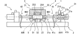
図2において、固定部21と、固定部22とは、被駆動体31に対して対称的に配置されている。固定部21と、固定部22とは、対称的な構造を有する。被駆動体31は、案内機構5に対して対称的な構造を有する。以下の説明では、第1のアクチュエータ素子41に関連する部分について説明する。この説明は、第2のアクチュエータ素子42に関連する部分の説明として参照することができる。第1のアクチュエータ素子41に関連する部分として、固定部21と、被駆動体31に設けられた第3連結機構31cとがある。
In FIG. 2, the fixed
固定部21は、エンドスリーブ21aと、アンカブロック21cとを有する。エンドスリーブ21aは、アクチュエータ素子41の端部に連結されている。エンドスリーブ21aは、アンカブロック21cに固定されている。アンカブロック21cは、基台2に固定されている。
The fixing
エンドスリーブ21aは、アクチュエータ素子41と同軸の円筒状部材である。エンドスリーブ21aは、多角形の角筒状でもよい。エンドスリーブ21aは、アクチュエータ素子41の固定端41bを受け入れる内穴を有する。エンドスリーブ21aは、固定端41bとエンドスリーブ21aとを連結する第1連結機構21bを有する。第1連結機構21bは、固定端41bと、エンドスリーブ21aとを、少なくともアクチュエータ素子41が回動力を出力するときにアクチュエータ軸AX41の周方向に関して連結する。
The
第1連結機構21bは、内穴とセットスクリュとによって提供されている。セットスクリュは、エンドスリーブ21aの内穴に向けて径方向に設けられている。セットスクリュは、固定端41bを径方向に締め付けることにより、固定端41bと、エンドスリーブ21aとを、軸方向および周方向に関して連結している。
The first connecting
第1連結機構21bは、多様な機構によって提供することができる。例えば、第1連結機構21bは、放射状に配置された複数のセットスクリュ、固定端41bを径方向に締め付けるチャック機構、固定端41bを径方向に締め付けるかしめスリーブなどによって提供することができる。第1連結機構21bは、アクチュエータ軸AX41に沿って、エンドスリーブ21aに対する固定端41bの軸方向移動を許容してもよい。例えば、固定端41bが制限された範囲内において、軸方向に移動できるように、固定端41bと、エンドスリーブ21aとを連結してもよい。例えば、スプリングまたはゴムのような弾性部材を用いることができる。第1連結機構21bは、開閉可能な機構によって提供されてもよい。例えば、第1連結機構21bは、固定端41bを周方向に固定している状態と、固定端41bを周方向に回動可能としている状態とを切替可能な電磁的機構により提供することができる。
The first connecting
アンカブロック21cは、エンドスリーブ21aを受け入れる内穴を有する。アンカブロック21cは、エンドスリーブ21aとアンカブロック21cとを連結する第2連結機構21dを有する。第2連結機構21dは、エンドスリーブ21aとアンカブロック21cとを、少なくともアクチュエータ素子41が回動力を出力するときにアクチュエータ軸AX41の周方向に関して連結する。
The
第2連結機構21dは、内穴とセットスクリュとによって提供されている。セットスクリュは、アンカブロック21cの内穴に向けて径方向に設けられている。セットスクリュは、エンドスリーブ21aを径方向に締め付けることにより、エンドスリーブ21aとアンカブロック21cとを、軸方向および周方向に関して連結している。
The second connecting
第2連結機構21dは、多様な機構によって提供することができる。例えば、第2連結機構21dは、放射状に配置された複数のセットスクリュ、エンドスリーブ21aを径方向に締め付けるチャック機構、エンドスリーブ21aを径方向に締め付けるかしめスリーブなどによって提供することができる。第2連結機構21dは、アクチュエータ軸AX41に沿って、エンドスリーブ21aの軸方向移動を許容してもよい。例えば、エンドスリーブ21aが制限された範囲内において、軸方向に移動できるように、アンカブロック21cと、エンドスリーブ21aとを連結してもよい。例えば、スプリングまたはゴムのような弾性部材を用いることができる。第2連結機構21dは、開閉可能な機構によって提供されてもよい。例えば、第2連結機構21dは、アクチュエータ素子41の端部を周方向に固定している状態と、アクチュエータ素子41の端部を周方向に回動可能としている状態とを切替可能な電磁的機構により提供することができる。
The second connecting
被駆動体31は、アクチュエータ素子41の出力端41cを受け入れる内穴を有する。被駆動体31は、被駆動体31と出力端41cとを連結する第3連結機構31aを有する。第3連結機構31aは、出力端41cと被駆動体31とを、少なくともアクチュエータ素子41が回動力を出力するときにアクチュエータ軸AX41の周方向に関して連結する。
The driven
第3連結機構31aは、内穴とセットスクリュとによって提供されている。セットスクリュは、被駆動体31の内穴に向けて径方向に設けられている。セットスクリュは、出力端41cを径方向に締め付けることにより、被駆動体31と出力端41cとを、軸方向および周方向に関して連結している。
The third connecting
第3連結機構31aは、多様な機構によって提供することができる。例えば、第3連結機構31aは、放射状に配置された複数のセットスクリュ、出力端41cを径方向に締め付けるチャック機構、出力端41cを径方向に締め付けるかしめスリーブなどによって提供することができる。第3連結機構31aは、アクチュエータ軸AX41に沿って、被駆動体31に対する出力端41cの軸方向移動を許容してもよい。例えば、出力端41cが制限された範囲内において、軸方向に移動できるように、出力端41cと、被駆動体31とを連結してもよい。例えば、スプリングまたはゴムのような弾性部材を用いることができる。第3連結機構31aは、開閉可能な機構によって提供されてもよい。例えば、第3連結機構31aは、出力端41cを周方向に固定している状態と、出力端41cを周方向に回動可能としている状態とを切替可能な電磁的機構により提供することができる。
The third connecting
被駆動体31は、案内機構5によって回動可能に支持されている。案内機構5は、シャフト51とガイドボア52とを有する。シャフト51は、回動軸AXRの同軸の円筒状部材によって提供されている。シャフト51は、被駆動体31に固定されている。シャフト51の両端が、被駆動体31に固定されている。被駆動体31は、シャフト51を有する。ガイドボア52は、支持部23に設けられている。支持部23は、ガイドボア52を有する。支持部23は、被駆動体31を支持するための部材である。支持部23は、基台2に固定されている。支持部23は、ブロックである。ガイドボア52は、支持部23を貫通する貫通穴によって提供されている。ガイドボア52は、シャフト51を受け入れている。ガイドボア52は、シャフト51の回転を許容する。この結果、支持部23は、被駆動体31を回転可能に支持している。
The driven
シャフト51の外面と、ガイドボア52の内面とは、部分的に接触している。シャフト51の外面と、ガイドボア52の内面とは、被駆動体31が回動すると、互いに摺動する。被駆動体31は、シャフト51の周りにおいて案内されている。シャフト51およびガイドボア52を提供する部材は、低摩擦材料製である。シャフト51、またはガイドボア52を提供する部材を、低摩擦材料製としてもよい。シャフト51とガイドボア52との間の摩擦が抑制される。
The outer surface of the
支持部23は、その両端面において、被駆動体31と対向している。支持部23は、その両端面において、部分的に被駆動体31と接触している。支持部23と被駆動体31とは、被駆動体31が回動すると、互いに摺動する。
The
アクチュエータ素子41の熱は、アクチュエータ素子41の全体から、外部環境へ放熱される。アクチュエータ素子41の熱は、固定端41bから、固定部21を経由して放熱される。このとき、第1連結機構21b、および第2連結機構21dは、放熱経路の熱的な抵抗を下げるために貢献する。さらに、アクチュエータ素子41の熱は、出力端41cから、被駆動体31を経由して放熱される。アクチュエータ素子41の熱は、出力端41cから、被駆動体31、支持部23、および基台2を経由して放熱される場合がある。このとき、第3連結機構31aは、放熱経路の熱的な抵抗を下げるために貢献する。
The heat of the
さらに、被駆動体31と支持部23との間の接触、および/またはシャフト51とガイドボア52との間の接触も、放熱経路の熱的な抵抗を下げるために貢献する。アクチュエータ素子41の熱は、出力端41cから、被駆動体31、被駆動体31と支持部23との間の接触、および支持部23を経由して放熱される。また、アクチュエータ素子41の熱は、出力端41cから、被駆動体31を通り、シャフト51、シャフト51とガイドボア52との間の接触、および支持部23を経由して放熱される。このように、アクチュエータ素子41は、被駆動体31および案内機構5を経由して放熱する。
Further, the contact between the driven
図3において、アクチュエータ素子41は、素材線41a、固定端41b、出力端41c、および発熱線41dを有する。素材線41aは、上述のポリマ繊維である。発熱線41dは、エネルギ増減装置71の一部でもある。発熱線41dは、素材線41aのエネルギを増減させるためのエネルギ伝達部品でもある。発熱線41dは、素材線41aの表面上において、直接的に、または間接的に配置されている。発熱線41dは、螺旋状、またはコイル状である。発熱線41dは、通電によって発熱する金属線である。発熱線41dは、白金線、銅線などによって提供できる。発熱線41dは、ニクロム線によって提供されている。発熱線41dは、丸線、角線、または金属箔によって提供することができる。発熱線41dは、素材線41aの表面に貼り付けられている。
In FIG. 3, the
発熱線41dは、通電されると、発熱する。発熱線41dにより供給される熱は、素材線41aに伝わり、素材線41aの温度を上昇させる。一方で、発熱線41dは、通電が遮断されると、発熱を停止する。素材線41aの熱は、外部環境へ放熱される。このとき、出力端41cにおける第3連結機構31aと、案内機構5とが放熱に貢献する。このため、アクチュエータ素子41において大きい温度差を実現することができる。
The
図4において、被駆動体31を揺動運動させるための制御処理180が図示されている。制御処理180は、制御装置70における制御処理の一部である。
In FIG. 4, a
ステップ181では、可動装置1の揺動が求められている(ON)か、否(OFF)かを判定する。例えば、走査型の赤外線センサを作動させることが求められている場合、揺動ONとなる。走査型の赤外線センサを作動させることが求められていない場合、揺動OFFとなる。揺動OFFの場合、制御を終了する。揺動ONの場合、ステップ182とステップ183とによるループ処理へ進む。ステップ182は、第1のアクチュエータ素子41を加熱するための処理である。ステップ183は、第2のアクチュエータ素子42を加熱するための処理である。ステップ182とステップ183とを交互に繰り返すことにより、被駆動体31は揺動的に動作する。ステップ184では、可動装置1の揺動が求められている(ON)か、否(OFF)かを判定する。
In
ステップ182は、被駆動体31を正転方向へ回転させる処理である。正転方向は、第1のアクチュエータ素子41から見て、被駆動体31を時計回り方向に回転させる方向である。ステップ182は、ステップ185と、ステップ186とを有する。
Step 182 is a process of rotating the driven
ステップ185では、まず、第1のアクチュエータ素子41を活性化させる。ステップ185では、第1のアクチュエータ素子41の発熱線41dに通電する。具体的には、制御装置70は、エネルギ増減装置71から発熱線41dに通電する。ステップ185の処理は、第1のアクチュエータ素子41が正転方向へ所定角度のねじりを出力するように実行される。例えば、回転角センサによって被駆動体31の回転角度を検出し、所定角度の回動が得られるまで、ステップ185が継続される。これに代えて、タイマ処理によって、ステップ185の処理を一定時間継続してもよい。
In
ステップ186では、第2のアクチュエータ素子42を不活性化させる。ステップ186では、第2のアクチュエータ素子42の発熱線42dへの通電を遮断する。具体的には、制御装置70は、エネルギ増減装置72から発熱線42dへの通電を遮断する。
In
ステップ183は、被駆動体31を逆転方向へ回転させる処理である。ステップ183は、ステップ187と、ステップ188とを有する。
Step 183 is a process of rotating the driven
ステップ187では、まず、第2のアクチュエータ素子42を活性化させる。ステップ187では、第2のアクチュエータ素子42の発熱線に通電する。具体的には、制御装置70は、エネルギ増減装置72から発熱線に通電する。
In
ステップ188では、第1のアクチュエータ素子41を不活性化させる。ステップ188では、第1のアクチュエータ素子41の発熱線への通電を遮断する。具体的には、制御装置70は、エネルギ増減装置71から発熱線への通電を遮断する。
In
この実施形態では、活性化は、発熱線41dへの通電に対応する。不活性化は、発熱線41dへの通電の遮断に対応する。活性化と不活性化との語の対は、加熱と放熱との語の対に、付勢と消勢との語の対に、アクティブとスタンバイとの語の対に対応付けることができる。
In this embodiment, the activation corresponds to energization of the
制御装置70は、アクチュエータ素子41のエネルギが増加する期間と、アクチュエータ素子41のエネルギが減少する期間とを交互に繰り返すようにエネルギ増減装置71を制御する。この結果、2つのアクチュエータ素子41、42が交互に能動的に駆動される。第1のアクチュエータ素子41が能動的に正転方向のねじり変形を出力しているときに、第2のアクチュエータ素子42は受動的に正転方向へ駆動される。逆に、第2のアクチュエータ素子42が能動的に逆転方向のねじり変形を出力しているときに、第1のアクチュエータ素子41は受動的に逆転方向へ駆動される。2つのアクチュエータ素子41、42が使用され、それらが交互に駆動されるから、両方向に関して安定的な回動出力が得られる。
The
以上に述べたこの実施形態によると、静かな可動装置1を提供することができる。特に、可動装置1が室内に設置される装置に利用される場合に有利である。例えば、静かな、走査型の赤外線センサが得られる。可動装置1は、案内機構5を備えるから、被駆動体31の振動が抑制される。特に、回動軸AXRに交差する方向、すなわち回動軸AXRに対する上下方向、および左右方向の振動が抑制される。案内機構5は、アクチュエータ軸AX41と同軸の回動軸AXRを規定するから、アクチュエータ素子41のねじり変形を直接的に取り出すことができる。さらに、案内機構5は、アクチュエータ素子41の放熱に貢献する。
According to this embodiment described above, the quiet
第2実施形態
この実施形態は、先行する実施形態を基礎的形態とする変形例である。上記実施形態では、支持部23と被駆動体31とが直接的に接触可能である。これに代えて、この実施形態では、支持部23と被駆動体31との間に、摺動部材253、254が設けられている。
Second Embodiment This embodiment is a modification based on the preceding embodiment. In the above embodiment, the
図5に図示されるように、回動軸AXRに沿って対向する支持部23と被駆動体31との間には、摺動部材253、254が配置されている。摺動部材253、254は、環状の部材である。摺動部材253、254は、ワッシャとも呼ぶことができる。摺動部材253、254は、ポリテトラフルオロエチレン製である。摺動部材253、254は、支持部23と被駆動体31との接触部における摺動抵抗を抑制する。摺動部材253、254は、支持部23と被駆動体31とが広い面積において接触することを許容する。このため、被駆動体31から、摺動部材253、254を経由して、支持部23へ伝えられる熱を増加させることができる。
As shown in FIG. 5, sliding
第3実施形態
この実施形態は、先行する実施形態を基礎的形態とする変形例である。上記実施形態では、シャフト51とガイドボア52とが直接的に接触可能である。しかも、ガイドボア52は支持部23によって提供されている。これに代えて、この実施形態では、ガイドボア52が、スリーブ355によって提供されている。
Third Embodiment This embodiment is a modification based on the preceding embodiment. In the above embodiment, the
図6に図示されるように、支持部23は、ガイドボア52を提供するスリーブ355を有する。スリーブ355は、円筒状である。スリーブ355は、ポリテトラフルオロエチレン製である。スリーブ355は、シャフト51とガイドボア52との接触部における摺動抵抗を抑制する。スリーブ355は、シャフト51とガイドボア52とが広い面積において接触することを許容する。このため、被駆動体31から、シャフト51およびガイドボア52を経由して、支持部23へ伝えられる熱を増加させることができる。
As illustrated in FIG. 6, the
第4実施形態
この実施形態は、先行する実施形態を基礎的形態とする変形例である。上記実施形態では、支持部23と被駆動体31とが直接的に接触可能である。これに代えて、この実施形態では、支持部23と被駆動体31との間に、隙間、すなわち空洞が設けられている。
Fourth Embodiment This embodiment is a modification based on the preceding embodiment as a basic embodiment. In the above embodiment, the
図7に図示されるように、支持部23と被駆動体31との間には、支持部23の両側において、隙間G453と、隙間G454とが設けられている。隙間G453、G454は、回動軸AXRの軸方向に関する隙間を示す。隙間G453、G454は、空洞でもある。隙間G453、G454は、支持部23と被駆動体31との直接的な接触を抑制する。このため、支持部23と被駆動体31との間における摺動抵抗が抑制される。アクチュエータ素子41の熱は、被駆動体31から、シャフト51およびガイドボア52を経由して、支持部23へ放熱される。
As shown in FIG. 7, a gap G453 and a gap G454 are provided between the
アクチュエータ素子41は、エネルギの増減によってアクチュエータ軸AX41の軸方向に関する長さが変化する特性を有している。エネルギの増減に起因する長さ変動量Ltの典型的な例は、温度の上昇低下に起因するアクチュエータ素子41の伸縮である。アクチュエータ素子41は、想定される使用温度範囲において、所定の長さ変動量Ltを有する。例えば、−20°Cから+60°Cの範囲が想定される場合、所定の長さ変動量Ltを有する。アクチュエータ軸AX41の軸方向における隙間G453、G454の長さは、所定の長さ変動量Ltより大きい。すなわち、隙間G453、または隙間G454の長さは、シャフト51とガイドボア52との間の相対的な移動可能な長さに対応している。そして、G453>Lt、およびG454>Ltである。これにより、アクチュエータ素子41が伸縮しても、被駆動体31と支持部23との間の直接的な接触が抑制される。
The
第5実施形態
この実施形態は、先行する実施形態を基礎的形態とする変形例である。上記実施形態では、被駆動体31とシャフト51とが固定されており、ガイドボア52は支持部23に設けられている。これに代えて、この実施形態では、支持部523とシャフト551とが固定されており、被駆動体531にガイドボア552が設けられている。この実施形態の構造は、他の実施形態と組合せ可能である。
Fifth Embodiment This embodiment is a modification based on the preceding embodiment as a basic embodiment. In the above embodiment, the driven
図8に図示されるように、支持部523とシャフト551とが固定されており、被駆動体531にガイドボア552が設けられている。支持部523は、2本のブロックを有する。支持部523は、シャフト551を支持するように構成されている。シャフト551は、その両端部で、支持部23に固定されている。支持部523は、シャフト551を有する。被駆動体531は、断面E字型である。被駆動体531は、ガイドボア552を有する。この実施形態でも、案内機構5が提供される。この実施形態では、2本の支持部523と、E字型の被駆動体531が使用される。このため、被駆動体531の表面に広い放熱面積が得られる。また、被駆動体531から支持部523へ熱を伝える対向面を増加させることができる。
As shown in FIG. 8, the
第6実施形態
この実施形態は、先行する実施形態を基礎的形態とする変形例である。上記実施形態では、2つのアクチュエータ素子41、42が利用されている。これに代えて、ひとつのアクチュエータ素子41だけを備えてもよい。この場合、第2のアクチュエータ素子42に代えて、受動的な回動機構を用いることができる。受動的な回動機構は、ゴム、樹脂製バネ、金属製バネ、空気バネなど多様な機構により提供することができる。受動的な回動機構は、戻し機構と呼ばれる。
Sixth Embodiment This embodiment is a modification based on the preceding embodiment. In the above embodiment, two
図9において、可動装置1は、第2のアクチュエータ素子42に代えて、戻し機構622を有する。戻し機構622は、受動的な弾性部材661と、固定部662と、固定部663とを有する。固定部662は、基台2に固定されたブロックである。固定部663は、被駆動体31に固定されている。
In FIG. 9, the
弾性部材661は、金属製のコイルバネである。弾性部材661は、自由状態よりも引っ張られることにより、被駆動体31に反時計周り方向の力を作用させる。弾性部材661は、被駆動体31の回動範囲M631の一端を基準位置とする。弾性部材661は、アクチュエータ素子41のねじり運動によって引っ張られるように配置されている。弾性部材661は、矢印M41の方向への回動力に抗して、戻し力を作用させる。この結果、アクチュエータ素子41が間欠的に駆動されることにより、言い換えると、周期的に活性化状態と不活性化状態とを繰り返すことにより、被駆動体31は、回動範囲M631において、回動運動する。
The
この実施形態によると、ひとつのアクチュエータ素子41によって往復的な被駆動体31の動きを得ることができる。しかも、案内機構5を備えるから、被駆動体31が安定する。この実施形態の構成は、先行する他の実施形態においても利用可能である。
According to this embodiment, the reciprocating movement of the driven
他の実施形態
この明細書における開示は、例示された実施形態に制限されない。開示は、例示された実施形態と、それらに基づく当業者による変形態様を包含する。例えば、開示は、実施形態において示された部品および/または要素の組み合わせに限定されない。開示は、多様な組み合わせによって実施可能である。開示は、実施形態に追加可能な追加的な部分をもつことができる。開示は、実施形態の部品および/または要素が省略されたものを包含する。開示は、ひとつの実施形態と他の実施形態との間における部品および/または要素の置き換え、または組み合わせを包含する。開示される技術的範囲は、実施形態の記載に限定されない。開示されるいくつかの技術的範囲は、請求の範囲の記載によって示され、さらに請求の範囲の記載と均等の意味及び範囲内での全ての変更を含むものと解されるべきである。
Other Embodiments The disclosure herein is not limited to the exemplified embodiments. The disclosure includes exemplary embodiments and modifications by those skilled in the art based on them. For example, disclosure is not limited to the parts and / or element combinations shown in the embodiments. Disclosure can be carried out in various combinations. The disclosure can have additional parts that can be added to the embodiment. Disclosures include those in which the parts and / or elements of the embodiment have been omitted. Disclosures include replacement or combination of parts and / or elements between one embodiment and another. The technical scope disclosed is not limited to the description of the embodiments. Some technical scopes disclosed are indicated by the claims description and should be understood to include all modifications within the meaning and scope equivalent to the claims statement.
先行する複数の実施形態では、シャフト51、551と、ガイドボア52、552とによって案内機構5を提供した。シャフト51、551と、ガイドボア52、552とは、いわゆる軸受機構を提供している。案内機構5を提供する軸受機構は、実施形態のような摺動軸受の他に、ボールベアリング、流体軸受、および磁力軸受など多くの機構によって提供可能である。この実施形態では、アクチュエータ素子41、42によって出力可能な回転トルクの上限に配慮して、比較的簡単で軽量な摺動軸受を採用している。
In a plurality of preceding embodiments, the
先行する複数の実施形態では、別体のシャフト51、551を、被駆動体31または支持部523に固定した。これに代えて、被駆動体31または支持部523にシャフトを一体的に形成してもよい。例えば、シャフト51に代わる円柱部分を、被駆動体31または支持部523に機械加工によって形成することができる。また、シャフト51に代わる円柱部分を、被駆動体31または支持部523にインサート成形することができる。
In a plurality of preceding embodiments,
先行する実施形態に加えて、固定部は、機械的に回転方向を制限する機構を備えることができる。例えば、固定部には、ラチェット機構を設けることができる。ラチェット機構は、例えば、固定端41bが矢印M42の方向へ回転する場合には、固定端41bを固定する。逆に、固定端41bに矢印M41の方向へ回転する場合には、固定端41bを開放する。ラチェット機構は、能動的な変形を許容するように固定状態となり、受動的な変形を無効化するように開放状態となる。
In addition to the preceding embodiments, the fixation can be provided with a mechanism that mechanically limits the direction of rotation. For example, the fixed portion may be provided with a ratchet mechanism. The ratchet mechanism fixes the
先行する実施形態に加えて、固定端41bまたは出力端41cにおける固定力を可変としてもよい。この場合、電気的に固定力を可変に制御可能な固定部を設けてもよい。固定部21、22による固定力は、開放状態と固定状態とに、または強弱に変更されてもよい。例えば、連結機構21dは、エンドスリーブ21aの外周面に強く締め付けられた状態と、エンドスリーブ21aの外周面に弱く押し当てられた状態とに切り換えられてもよい。この場合、エンドスリーブ21aは、セットスクリュと摩擦しながら回転する。
In addition to the preceding embodiment, the fixing force at the
先行する実施形態では、素材線41aに発熱線41dを直接的に巻き付けている。これに代えて、素材線41aと発熱線41dとの間に部材を配置してもよい。例えば、電気絶縁性であって、優れた熱伝導性をもつ支持部材を配置することができる。支持部材は、素材線41aに巻き付けられる絶縁紙、または素材線41aを内部に収容するガラス筒によって提供することができる。このように、ひとつの態様では、発熱線41dは素材線41aに直接的に接触しているが、他の態様では、発熱線41dは素材線41aに直接的に接触することなく、巻き付けられた形状を有する。支持部材の内面に発熱部材を配置してもよい。
In the preceding embodiment, the
先行する実施形態では、発熱線41dによる加熱と、放熱とによって、素材線41aのエネルギの増減を実現している。これに代えて、冷却装置による冷却と、放冷とによって、素材線41aのエネルギの増減を実現することができる。例えば、ペルチェ効果素子を素材線41aに沿って配置することができる。ペルチェ効果素子は、エネルギ伝達部品を提供する。この場合、素材線41aは、冷却されると、熱膨張または熱収縮してねじり変形を生じる。
In the preceding embodiment, the energy of the
先行する実施形態では、発熱線41dとしてニクロム線を用いている。これに代えて、エネルギ伝達部品は、多様な電気的な発熱部材によって提供できる。例えば、発熱部材は、導電性高分子または導電性金属皮膜と呼ばれる導電性薄膜によって提供されてもよい。この場合、膜は、素材線41aの表面に形成される。例えば、導電性高分子または導電性金属皮膜は、素材線41aの表面にメッキ、合成、スパッタなど多様な手法によって形成される。その形状は素材線41aの周囲に巻き付いている螺旋状である。また、素材線41aとは別に形成された、リボン状の導電性高分子または導電性金属皮膜を巻くことによって、螺旋状の発熱部材を形成し、素材線41aの外側に配置してもよい。
In the preceding embodiment, a nichrome wire is used as the
1 可動装置、 2 基台、
21 固定部、 22 固定部、 23 支持部、
3 可動部、 31 被駆動体、
4 アクチュエータ機構、
41 アクチュエータ素子、 42 アクチュエータ素子、
41a 素材線、 41b 固定端、 41c 出力端、
41d 発熱線、
5 案内機構、 51 シャフト、 52 ガイドボア、
7 制御システム、 70 制御装置、
71、72 エネルギ増減装置、
253 摺動部材、 254 摺動部材、
355 スリーブ、
G453 隙間、 G454 隙間、
551 シャフト、 552 ガイドボア、
523 支持部、 531 被駆動体、
622 戻し機構、 661 弾性部材、
AX41 アクチュエータ軸、 AXR 回動軸。
1 movable device, 2 bases,
21 Fixed part, 22 Fixed part, 23 Support part,
3 Moving parts, 31 Driven body,
4 Actuator mechanism,
41 Actuator element, 42 Actuator element,
41a material wire, 41b fixed end, 41c output end,
41d heating wire,
5 Guide mechanism, 51 shaft, 52 guide bore,
7 Control system, 70 Control device,
71, 72 Energy increase / decrease device,
253 sliding member, 254 sliding member,
355 sleeve,
G453 gap, G454 gap,
551 shaft, 552 guide bore,
523 Support, 531 Driven Body,
622 return mechanism, 661 elastic member,
AX41 actuator shaft, AXR rotation shaft.
Claims (8)
前記アクチュエータ軸上において前記アクチュエータ素子と連結された被駆動体(31、531)と、
前記アクチュエータ軸と同軸の回動軸(AXR)の周りにおいて、前記アクチュエータ素子のねじり変形を直接的に取り出すように、前記被駆動体を案内する案内機構(5)と、
前記アクチュエータ素子のエネルギを増減させるエネルギ増減装置(71、72)と、
前記アクチュエータ素子のエネルギが増加する期間と、前記アクチュエータ素子のエネルギが減少する期間とを交互に繰り返すように前記エネルギ増減装置を制御する制御装置(70)とを備え、
前記アクチュエータ素子は、前記被駆動体に対して対称的に配置されており、変形方向が対称的な方向である第1のアクチュエータ素子(41)、および、第2のアクチュエータ素子(42)とを備え、
前記制御装置は、
前記第1のアクチュエータ素子のエネルギが増加し、前記第2のアクチュエータ素子のエネルギが減少する期間と、
前記第1のアクチュエータ素子のエネルギが減少し、前記第2のアクチュエータ素子のエネルギが増加する期間とを交互に繰り返して前記被駆動体を揺動させ、
前記案内機構は、シャフト(51、551)と、ガイドボア(52、552)とを備え、前記被駆動体は、前記シャフトの周りにおいて案内されている可動装置。 Actuator elements (41, 42) that deform around the actuator shafts (AX41, AX42) due to increase or decrease in energy, and
A driven body (31, 513) connected to the actuator element on the actuator shaft,
A guide mechanism (5) that guides the driven body so as to directly take out the torsional deformation of the actuator element around the rotation shaft (AXR) coaxial with the actuator shaft.
Energy increase / decrease devices (71, 72) that increase / decrease the energy of the actuator element, and
A control device (70) for controlling the energy increase / decrease device so as to alternately repeat a period in which the energy of the actuator element increases and a period in which the energy of the actuator element decreases is provided.
The actuator element is arranged symmetrically with respect to the driven body, and the first actuator element (41) and the second actuator element (42) whose deformation direction is symmetrical are arranged. Prepare,
The control device is
The period during which the energy of the first actuator element increases and the energy of the second actuator element decreases, and
The driven body is swung by alternately repeating the period in which the energy of the first actuator element decreases and the energy of the second actuator element increases .
The guide mechanism includes a shaft (51 and 551), and a guide bore (52,552), the driven member is movable device that is guided in around the shaft.
前記アクチュエータ素子は、エネルギの増減によって前記アクチュエータ軸の方向に関する長さが変化する長さ変動量を有し、
前記シャフトと前記ガイドボアとの間の相対的な移動可能な長さは、前記アクチュエータ素子の前記長さ変動量より大きい請求項1に記載の可動装置。 The shaft and the guide bore are relatively movable in the axial direction.
The actuator element has a length variation amount in which the length with respect to the direction of the actuator shaft changes as the energy increases or decreases.
The movable device according to claim 1 , wherein the relative movable length between the shaft and the guide bore is larger than the length fluctuation amount of the actuator element.
前記被駆動体(31)は、前記シャフト(51)を有し、
前記支持部(23)は、前記ガイドボア(52)を有する請求項1または請求項2に記載の可動装置。 Further, a fixed base (2) and a support portion fixed to the base are provided.
The driven body (31) has the shaft (51).
The movable device according to claim 1 or 2, wherein the support portion (23) has the guide bore (52).
前記被駆動体(531)は、前記ガイドボア(552)を有し、
前記支持部(523)は、前記シャフト(551)を有する請求項1または請求項2に記載の可動装置。 Further, a fixed base (2) and a support portion fixed to the base are provided.
The driven body ( 531 ) has the guide bore (552) .
The movable device according to claim 1 or 2 , wherein the support portion ( 523 ) has the shaft (551).
Priority Applications (4)
| Application Number | Priority Date | Filing Date | Title |
|---|---|---|---|
| JP2017057941A JP6841115B2 (en) | 2017-03-23 | 2017-03-23 | Movable device |
| CN201880018754.6A CN110462208A (en) | 2017-03-23 | 2018-03-07 | Movable device |
| PCT/JP2018/008672 WO2018173742A1 (en) | 2017-03-23 | 2018-03-07 | Movable device |
| US16/575,097 US11002256B2 (en) | 2017-03-23 | 2019-09-18 | Movable device |
Applications Claiming Priority (1)
| Application Number | Priority Date | Filing Date | Title |
|---|---|---|---|
| JP2017057941A JP6841115B2 (en) | 2017-03-23 | 2017-03-23 | Movable device |
Publications (3)
| Publication Number | Publication Date |
|---|---|
| JP2018161009A JP2018161009A (en) | 2018-10-11 |
| JP2018161009A5 JP2018161009A5 (en) | 2019-05-30 |
| JP6841115B2 true JP6841115B2 (en) | 2021-03-10 |
Family
ID=63585324
Family Applications (1)
| Application Number | Title | Priority Date | Filing Date |
|---|---|---|---|
| JP2017057941A Active JP6841115B2 (en) | 2017-03-23 | 2017-03-23 | Movable device |
Country Status (4)
| Country | Link |
|---|---|
| US (1) | US11002256B2 (en) |
| JP (1) | JP6841115B2 (en) |
| CN (1) | CN110462208A (en) |
| WO (1) | WO2018173742A1 (en) |
Families Citing this family (3)
| Publication number | Priority date | Publication date | Assignee | Title |
|---|---|---|---|---|
| US10975851B2 (en) * | 2019-04-01 | 2021-04-13 | Johnson Controls Technology Company | Torque box actuator with shape memory alloy |
| CN110848104B (en) * | 2019-12-01 | 2021-09-28 | 西北工业大学 | Mechanical iris device driven by shape memory alloy wire |
| GB202116400D0 (en) * | 2021-11-15 | 2021-12-29 | Cambridge Mechatronics Ltd | An actuator assembly |
Family Cites Families (30)
| Publication number | Priority date | Publication date | Assignee | Title |
|---|---|---|---|---|
| US3665705A (en) * | 1969-11-10 | 1972-05-30 | Edwin S Christensen | Thermal engines |
| US4175390A (en) * | 1974-12-27 | 1979-11-27 | George Koslow | Solid stress motor |
| US4553394A (en) * | 1983-04-15 | 1985-11-19 | Friedrich Weinert | Spindle drive with expansible chamber motors |
| US4887430A (en) * | 1988-12-21 | 1989-12-19 | Eaton Corporation | Bistable SME actuator with retainer |
| US5127228A (en) * | 1991-02-07 | 1992-07-07 | Swenson Steven R | Shape memory bi-directional rotary actuator |
| JPH09325818A (en) * | 1996-06-05 | 1997-12-16 | Tokuji Sawara | Driving device |
| US6065934A (en) * | 1997-02-28 | 2000-05-23 | The Boeing Company | Shape memory rotary actuator |
| US6129181A (en) * | 1998-05-26 | 2000-10-10 | Lockheed Corp | Constant force spring actuator |
| US6006522A (en) * | 1998-08-10 | 1999-12-28 | Lockheed Martin Corporation | Translational actuator |
| JP3638016B2 (en) * | 2001-10-01 | 2005-04-13 | コニカミノルタフォトイメージング株式会社 | Drive device and drive control method using shape memory alloy |
| US6945045B2 (en) | 2001-10-01 | 2005-09-20 | Minolta Co., Ltd. | Driving apparatus |
| KR20060041164A (en) * | 2003-05-02 | 2006-05-11 | 알프마이어 프레치지온 악티엔게젤샤프트 바우그룹펜 운트 지스템뢰중엔 | Gauge pointer with integrated shape memory alloy actuator |
| US20040252005A1 (en) * | 2003-06-10 | 2004-12-16 | The Boeing Company | Shape memory alloy MEMS component deposited by chemical vapor deposition |
| EP2461180A1 (en) * | 2005-05-04 | 2012-06-06 | Volcano Corporation | Miniature actuator mechanism for intravascular imaging |
| JP4395180B2 (en) * | 2006-09-05 | 2010-01-06 | イヴァン ゴドレール | Motion conversion device |
| US7481055B2 (en) * | 2006-11-28 | 2009-01-27 | Thermotion Corporation | Rotary actuator |
| US9903350B2 (en) | 2012-08-01 | 2018-02-27 | The Board Of Regents, The University Of Texas System | Coiled and non-coiled twisted polymer fiber torsional and tensile actuators |
| US9488161B2 (en) * | 2013-03-21 | 2016-11-08 | Terry W. Thompson | Thermal expansion drive devices and related methods |
| US9638176B2 (en) * | 2013-05-10 | 2017-05-02 | The Boeing Company | Vortex generator using shape memory alloys |
| CN103352820B (en) * | 2013-07-12 | 2015-03-25 | 江苏大学 | Rotary device based on gear-rack transmission and driven by shape memory effect |
| US20170314539A1 (en) | 2014-10-22 | 2017-11-02 | Industry-University Cooperation Foundation Hanyang University | Rotation-type actuator actuated by temperature fluctuation or temperature gradient and energy harvesting device using same |
| CN104454414A (en) * | 2014-10-23 | 2015-03-25 | 上海卫星工程研究所 | SMA material-based drive device |
| WO2017022146A1 (en) * | 2015-08-04 | 2017-02-09 | パナソニックIpマネジメント株式会社 | Actuator |
| JP6802360B2 (en) * | 2016-04-29 | 2020-12-16 | リンテック・オブ・アメリカ・インコーポレイテッド | Bistable actuator device |
| JP6714858B2 (en) | 2016-09-12 | 2020-07-01 | 株式会社デンソー | Actuator device |
| WO2018055972A1 (en) * | 2016-09-20 | 2018-03-29 | 株式会社デンソー | Actuator device |
| JP6794892B2 (en) | 2017-03-23 | 2020-12-02 | 株式会社デンソー | Movable device |
| JP6784206B2 (en) | 2017-03-23 | 2020-11-11 | 株式会社デンソー | Movable device |
| JP2018161010A (en) | 2017-03-23 | 2018-10-11 | 株式会社デンソー | Movable device, manufacturing method of movable device, and control method of movable device |
| JP2018159351A (en) | 2017-03-23 | 2018-10-11 | 株式会社デンソー | Movable device |
-
2017
- 2017-03-23 JP JP2017057941A patent/JP6841115B2/en active Active
-
2018
- 2018-03-07 CN CN201880018754.6A patent/CN110462208A/en active Pending
- 2018-03-07 WO PCT/JP2018/008672 patent/WO2018173742A1/en active Application Filing
-
2019
- 2019-09-18 US US16/575,097 patent/US11002256B2/en active Active
Also Published As
| Publication number | Publication date |
|---|---|
| JP2018161009A (en) | 2018-10-11 |
| WO2018173742A1 (en) | 2018-09-27 |
| US20200011305A1 (en) | 2020-01-09 |
| US11002256B2 (en) | 2021-05-11 |
| CN110462208A (en) | 2019-11-15 |
Similar Documents
| Publication | Publication Date | Title |
|---|---|---|
| JP6841115B2 (en) | Movable device | |
| JP6794892B2 (en) | Movable device | |
| JP6784206B2 (en) | Movable device | |
| WO2018047505A1 (en) | Actuator device | |
| CN101896719A (en) | Shape memory alloy actuation apparatus | |
| JP2007004121A (en) | Motor, motor device and lens drive mechanism using the same | |
| JP2022532931A (en) | Varifocal assembly | |
| US11025178B2 (en) | Actuator device | |
| WO2018055972A1 (en) | Actuator device | |
| US11596294B2 (en) | Variable stiffness device and method of varying stiffness | |
| WO2018173743A1 (en) | Movable device, production method therefor, and control method therefor | |
| Mammano et al. | Design and characterization of a continuous rotary minimotor based on shape-memory wires and overrunning clutches | |
| WO2018173744A1 (en) | Movable device | |
| US20220290659A1 (en) | Thermal actuator arrangement having improved reset time | |
| JP2009122605A (en) | Drive unit using shape memory alloy | |
| WO2019159754A1 (en) | Actuator device | |
| WO2022007201A1 (en) | Drive assembly, camera module, and electronic device with photography function | |
| JP2019146466A (en) | Actuator device | |
| KR101681221B1 (en) | Piezoelectric stepping motor | |
| JP2019080439A (en) | Movable device | |
| KR101648805B1 (en) | Piezoelectric stepping motor | |
| GB2612116A (en) | SMA actuator assembly | |
| Mammano et al. | Optimization and testing of a continuous rotary motor based on shape memory wires and overrunning clutches | |
| WO2022152375A1 (en) | Shape memory alloy actuator architecture for driving adjustable aperture | |
| KR20220169988A (en) | Apparatus for moving camera lens |
Legal Events
| Date | Code | Title | Description |
|---|---|---|---|
| A521 | Written amendment |
Free format text: JAPANESE INTERMEDIATE CODE: A523 Effective date: 20190416 |
|
| A621 | Written request for application examination |
Free format text: JAPANESE INTERMEDIATE CODE: A621 Effective date: 20190416 |
|
| A131 | Notification of reasons for refusal |
Free format text: JAPANESE INTERMEDIATE CODE: A131 Effective date: 20200331 |
|
| A521 | Written amendment |
Free format text: JAPANESE INTERMEDIATE CODE: A523 Effective date: 20200518 |
|
| A131 | Notification of reasons for refusal |
Free format text: JAPANESE INTERMEDIATE CODE: A131 Effective date: 20200923 |
|
| A521 | Written amendment |
Free format text: JAPANESE INTERMEDIATE CODE: A523 Effective date: 20201103 |
|
| TRDD | Decision of grant or rejection written | ||
| A01 | Written decision to grant a patent or to grant a registration (utility model) |
Free format text: JAPANESE INTERMEDIATE CODE: A01 Effective date: 20210119 |
|
| A61 | First payment of annual fees (during grant procedure) |
Free format text: JAPANESE INTERMEDIATE CODE: A61 Effective date: 20210201 |
|
| R151 | Written notification of patent or utility model registration |
Ref document number: 6841115 Country of ref document: JP Free format text: JAPANESE INTERMEDIATE CODE: R151 |