WO2018173746A1 - Movable device - Google Patents
Movable device Download PDFInfo
- Publication number
- WO2018173746A1 WO2018173746A1 PCT/JP2018/008676 JP2018008676W WO2018173746A1 WO 2018173746 A1 WO2018173746 A1 WO 2018173746A1 JP 2018008676 W JP2018008676 W JP 2018008676W WO 2018173746 A1 WO2018173746 A1 WO 2018173746A1
- Authority
- WO
- WIPO (PCT)
- Prior art keywords
- driven body
- actuator
- actuator element
- energy
- connection member
- Prior art date
Links
Images


Definitions
- Patent Document 1 discloses a movable device that utilizes deformation of an actuator element.
- the deformation of the member is directly or indirectly used to mechanically move the driven body.
- an actuator element is an elongated synthetic fiber.
- the prior art does not sufficiently disclose a device that is a driven body or an electrical connection device with a device mounted on the driven body.
- the connecting device is required to suppress the load fluctuation applied to the actuator element. From another viewpoint, it is required to suppress a transient change in the load applied to the actuator element. These requests are strongly demanded as the driving force by the actuator element becomes weaker. In view of the above or other aspects not mentioned, there is a need for further improvements in mobile devices.
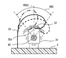
- FIG. 6 is a cross-sectional view taken along line VI-VI in FIG. 1. It is a perspective view of the movable device concerning at least one embodiment. It is a fragmentary sectional view of the movable device concerning at least one embodiment. It is sectional drawing in the IX-IX line of FIG. It is a fragmentary sectional view of the movable device concerning at least one embodiment.
- the movable device 1 has an element 32 mounted on the driven body 31.
- the element 32 provides an electrically active action or an electrically passive action.
- the element 32 is, for example, an electrical light source, an electrical blower, an electrical heat source, an electrical radio wave source, or an electrical magnetic source.
- the element 32 is, for example, an electrical sensor element.
- the movable device 1 may include a connection member that electrically connects the base 2 and the element 32 for electrical connection.
- the element 32 has an axis VR32 for the main function. For example, when the element 32 is a light source, the axis VR32 corresponds to the optical axis. For example, when the element 32 is a sensor, the axis VR32 corresponds to a detection axis.
- the shaft VR32 is swung by the rotation of the driven body 31.
- the axis VR32 is swung within the range of the rotation angle VRS.
- the movable device 1 is also a sensor device.
- the element 32 is a sensor element.
- the element 32 has an axis VR32 indicating a detection direction and a detection range.
- the element 32 detects a physical quantity in the direction of the axis VR32.
- the element 32 is provided by various elements such as an image sensor, an infrared sensor, an ultrasonic sensor, a radar antenna, an electromagnetic wave sensor, and a radiation sensor.
- the element 32 is an infrared sensor installed indoors.
- the detection signal of the element 32 is supplied to a device using infrared information by wire or wireless. Infrared information is supplied and used, for example, to an air conditioner.
- the movable device 1 is installed in a room such as a residence, an office, a vehicle, a ship, and an aircraft, and is used to collect information related to people in the room.
- the base 2 is placed in these rooms.
- the movable device 1 is moved so as to swing the axis VR32.
- the movable device 1 provides a sensor device that moves the axis VR32.
- the movement of the axis VR32 makes it possible to provide various sensor devices such as a directivity direction variable type, a tracking type, or a scanning type.
- a scanning sensor device is provided.
- the axis VR32 rotates about the rotation axis AXR.
- the axis VR32 is movable within a range of a predetermined rotation angle VRS along a plane extending in the width direction WD and the depth direction DD.
- the rotation angle VRS is the scanning range.
- the movable part 3 includes an electrical connection member 33.
- the connection member 33 electrically connects the base 2 and the element 32.
- the connection member 33 indirectly connects the base 2 and the driven body 31.
- a circuit for the element 32 is laid on the base 2.
- equipment for external connection may be installed.
- the connection member 33 may electrically connect the base 2 and the driven body 31. In this case, the electric wire of the element 32 is arranged via the driven body 31.
- the connecting member 33 is a flexible member that can be bent.
- the connection member 33 is a flexible plate-like member. As a result, the connecting member 33 allows the driven body 31 and the element 32 to rotate together by deforming itself.
- the connection member 33 is mainly formed of an elastic member that can be elastically deformed.
- the connection member 33 has a surface parallel to the rotation axis AXR.
- the connection member 33 is provided by a so-called flexible printed wiring board (FPC).
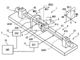
- the movable device 1 includes an actuator mechanism 4.
- the actuator mechanism 4 provides a rotational force for rotating the movable part 3.
- the actuator mechanism 4 is also a power source.
- the actuator mechanism 4 provides a rotational force so as to reciprocate.
- the actuator mechanism 4 has two actuator elements 41 and 42.
- the two actuator elements 41 and 42 are arranged on an extension line of the rotation axis AXR.
- the two actuator elements 41 and 42 are arranged on both sides of the driven body 31.
- the driven body 31 and the two actuator elements 41 and 42 are arranged in series. In the figure, the actuator elements 41 and 42 are illustrated with a little emphasis.
- the first actuator element 41 is connected to the driven body 31 and the fixed portion 21.
- the first actuator element 41 extends along the actuator axis AX41.
- the actuator axis AX41 is also the central axis of the first actuator element 41.
- the actuator shaft AX41 is located on the extension of the rotation shaft AXR.
- the actuator shaft AX41 and the rotation shaft AXR are coaxial.
- the second actuator element 42 is connected to the driven body 31 and the fixed portion 22.
- the second actuator element 42 extends along the actuator axis AX42.
- the actuator axis AX42 is also the central axis of the second actuator element 42.
- the actuator shaft AX42 is located on the extension of the rotation shaft AXR.
- the actuator shaft AX42 and the rotation shaft AXR are coaxial.
- the driven body 31 is disposed at the center of the base 2.
- the fixing portion 21 is provided at one end of the base 2.
- the fixing part 21 is fixed to the base 2.
- the fixing part 22 is provided at the other end of the base 2.
- the fixing part 22 is fixed to the base 2.
- the base 2 is made of a material that can maintain the shape of the movable device 1 against the force generated by the actuator mechanism 4.
- the base 2 is made of metal or resin. Part or the whole of the base 2 may be provided by a printed wiring board.
- the first actuator element 41 and the second actuator element 42 are arranged symmetrically with respect to the driven body 31.
- the first actuator element 41 and the second actuator element 42 have a symmetrical structure.
- the first actuator element 41 will be described. This description can be referred to as a description of the second actuator element 42.
- the first actuator element 41 has a fixed end 41 b that can be connected to the fixed portion 21.
- the fixed end 41b is connected to the fixed portion 21 when at least the first actuator element 41 outputs rotational power.
- the first actuator element 41 has an output end 41 c that can be connected to the driven body 31.
- the output end 41c is connected to the driven body 31 when at least the first actuator element 41 outputs rotational power.
- the driven body 31 is connected to the actuator element 41 on the actuator shaft AX41.
- the names of the fixed end 41b and the output end 41c are for convenience. In the following description, the fixed end 41b and the output end 41c may be simply referred to as ends.
- the first actuator element 41 has a rod shape.
- the first actuator element 41 has a shape that can be called an elongated rod shape or a fiber shape.
- the first actuator element 41 can be formed in a columnar shape or a cylindrical shape.
- the movable device 1 has a guide mechanism 5 for guiding the movement of the movable part 3.
- the guide mechanism 5 is provided between the support portion 23 provided on the base 2 and the driven body 31.
- the support part 23 is fixed to the base 2.
- the guide mechanism 5 allows the rotational movement of the driven body 31 around the height direction HD.
- the guide mechanism 5 suppresses the rotational motion around the depth direction DD and the rotational motion around the width direction WD.
- the guide mechanism 5 suppresses the vertical movement in the depth direction DD and the horizontal movement in the width direction WD of the movement of the driven body 31.
- the guide mechanism 5 may suppress the back-and-forth movement in the height direction HD.
- the guide mechanism 5 may allow back-and-forth movement in the height direction HD.
- the height direction HD can be defined as the roll axis, the width direction WD as the pitching axis, and the depth direction DD as the yaw axis.
- the guide mechanism 5 allows the driven body 31 to roll.
- the guide mechanism 5 may suppress excessive roll movement exceeding the available range. For example, a direct collision between the driven body 31 and the support portion 23 or an indirect collision via an elastic member limits the roll motion range.
- the guide mechanism 5 suppresses yawing motion and pitching motion of the driven body 31. Further, the guide mechanism 5 suppresses the vertical and horizontal movements of the driven body 31.
- the guide mechanism 5 may suppress the back-and-forth movement of the driven body 31.
- the guide mechanism 5 may allow the back-and-forth movement of the driven body 31 in some cases.
- the movable device 1 includes a control system 7.
- the control system 7 includes a control device (CNT) 70 and energy increase / decrease devices (EX1, EX2) 71, 72.
- the energy increasing / decreasing devices 71, 72 are devices that increase / decrease the energy of the two actuator elements 41, 42 in order to extract mechanical motion from the two actuator elements 41, 42.
- the energy increasing / decreasing devices 71 and 72 increase or decrease the energy of the two actuator elements 41 and 42 so as to rotate the two actuator elements 41 and 42.
- control device, signal source, and control object included in the control system provide various elements. At least some of these elements can be referred to as blocks for performing functions. In another aspect, at least some of these elements can be referred to as modules or sections that are interpreted as configurations. Furthermore, the elements included in the control system can also be referred to as means for realizing the functions only when intentional.
- the means and / or function provided by the control system can be provided by software recorded in a substantial memory device and a computer that executes the software, software only, hardware only, or a combination thereof.
- the controller can be provided by an electronic circuit that is hardware, it can be provided by a digital circuit including a number of logic circuits, or an analog circuit.
- the two actuator elements 41 and 42 are actively deformed in one direction.
- the deformation directions of the two actuator elements 41 and 42 are opposite directions, that is, symmetrical directions.
- an active deformation is obtained in both directions, i.e. in a reciprocating direction.
- Actuator elements 41 and 42 are deformed around actuator axes AX41 and AX42 by increasing or decreasing thermal energy.
- the first actuator element 41 is deformed so as to be twisted when the temperature of the first actuator element 41 rises. Since the fixed end 41b is fixed by the fixing portion 21, the driven body 31 rotates in the direction of the arrow M41 that is the first direction.
- the second actuator element 42 is deformed so as to be twisted when the temperature of the second actuator element 42 rises. Since the fixed end 42b is fixed by the fixing portion 22, the driven body 31 rotates in the direction of the arrow M42 that is the second direction.
- the direction of the arrow M41 and the direction of the arrow M42 are symmetric with respect to the driven body 31. As a result, the driven body 31 rotates over the angular range indicated by the arrow M31.
- the arrow M31 corresponds to the rotation angle VRS of the axis VR32.
- the actuator elements 41 and 42 and the energy increasing / decreasing devices 71 and 72 that can be used in this embodiment include those described in JP-A-2016-42783.
- the content described in Japanese Patent Application Laid-Open No. 2016-42783 is incorporated by reference as an explanation of technical elements in this specification.
- the actuator elements 41 and 42 can be provided by various materials called artificial muscles. For example, materials such as synthetic resins, metals, shape memory alloys, and organic materials can be used.
- One example of the actuator elements 41 and 42 is a synthetic fiber.
- the synthetic fiber extends along an extension line of the rotation axis AXR.
- Synthetic fibers are elongated.
- Synthetic fibers are called polymer fibers.
- One typical example of a polymer fiber is a monofilament resin.
- the monofilament resin includes a polyamide resin and a polyethylene resin.
- a polymer fiber called nylon or polyethylene may have a torsional deformation amount with respect to a temperature change, and can be used as the actuator elements 41 and 42.
- the polymer forming the polymer fiber is oriented so as to extend along the actuator axes AX41 and AX42.
- the polymer may have a “twist” around the actuator axes AX41, AX42.
- the term “twist” may refer to a twist in a single fiber and may refer to a twist between multiple fibers.
- the twist deformation amount with respect to the temperature change of the polymer fiber may appear strongly along the direction of “twist” in the single fiber.
- the actuator elements 41 and 42 are single fibers.
- the amount of torsional deformation with respect to temperature change of the polymer fiber may appear along the direction of “twist” between the plurality of fibers.
- the actuator elements 41 and 42 may be a bundle of a plurality of polymer fibers twisted together.
- One example of the actuator elements 41 and 42 is a shape memory alloy.
- Shape memory alloys extending along the actuator axes AX41, AX42 can be used.
- the shape memory alloy can be used in various shapes such as a single rod shape and a coiled shape.
- the shape of the shape memory alloy is selected so as to obtain a torsional deformation amount with respect to a temperature change.
- Energy application and removal can be performed directly or indirectly.
- energy may be applied by an energy transmission component that directly contacts the actuator elements 41 and 42, or energy may be indirectly applied by an energy transmission component installed away from the actuator elements 41 and 42.
- the energy transmission component can be provided by, for example, an electrical heating member.
- the energy increasing / decreasing devices 71, 72 increase the thermal energy of the actuator elements 41, 42.
- the increase in thermal energy is realized, for example, by supplying current to the heat generating members provided in the actuator elements 41 and 42.
- the energy increasing / decreasing devices 71 and 72 decrease the thermal energy of the actuator elements 41 and 42 in order to return the actuator elements 41 and 42 from active rotation.
- the reduction of the thermal energy is realized, for example, by interrupting the current supply to the heat generating members provided in the actuator elements 41 and 42 to dissipate heat.
- the fixing portion 21 and the fixing portion 22 are arranged symmetrically with respect to the driven body 31.
- the fixed part 21 and the fixed part 22 have a symmetrical structure.
- the driven body 31 has a symmetrical structure with respect to the guide mechanism 5.
- portions related to the first actuator element 41 will be described. This description can be referred to as a description of portions related to the second actuator element 42.
- parts related to the first actuator element 41 there are a fixed portion 21 and a third coupling mechanism 31 c provided on the driven body 31.
- the fixing portion 21 has an end sleeve 21a and an anchor block 21c.
- the end sleeve 21 a is connected to the end of the actuator element 41.
- the end sleeve 21a is fixed to the anchor block 21c.
- the anchor block 21 c is fixed to the base 2.
- the end sleeve 21 a is a cylindrical member coaxial with the actuator element 41.
- the end sleeve 21a may be a polygonal rectangular tube.
- the end sleeve 21 a has an inner hole that receives the fixed end 41 b of the actuator element 41.
- the end sleeve 21a includes a first connecting mechanism 21b that connects the fixed end 41b and the end sleeve 21a.
- the first coupling mechanism 21b couples the fixed end 41b and the end sleeve 21a with respect to the circumferential direction of the actuator shaft AX41 when at least the actuator element 41 outputs turning force.
- the first connecting mechanism 21b is provided by an inner hole and a set screw.
- the set screw is provided in the radial direction toward the inner hole of the end sleeve 21a.
- the set screw connects the fixed end 41b and the end sleeve 21a in the axial direction and the circumferential direction by tightening the fixed end 41b in the radial direction.
- the first coupling mechanism 21b can be provided by various mechanisms.
- the first connecting mechanism 21b can be provided by a plurality of set screws arranged radially, a chuck mechanism for fastening the fixed end 41b in the radial direction, a caulking sleeve for fastening the fixed end 41b in the radial direction, and the like.
- the first connecting mechanism 21b may allow the axial movement of the fixed end 41b relative to the end sleeve 21a along the actuator axis AX41.
- the fixed end 41b and the end sleeve 21a may be coupled so that the fixed end 41b can move in the axial direction within a limited range.
- an elastic member such as a spring or rubber can be used.
- the first connection mechanism 21b may be provided by a mechanism that can be opened and closed.
- the first coupling mechanism 21b can be provided by an electromagnetic mechanism that can switch between a state in which the fixed end 41b is fixed in the circumferential direction and a state in which the fixed end 41b is rotatable in the circumferential direction. .
- the anchor block 21c has an inner hole for receiving the end sleeve 21a.
- the anchor block 21c has a second coupling mechanism 21d that couples the end sleeve 21a and the anchor block 21c.
- the second coupling mechanism 21d couples the end sleeve 21a and the anchor block 21c with respect to the circumferential direction of the actuator shaft AX41 when at least the actuator element 41 outputs turning force.
- the second connecting mechanism 21d is provided by an inner hole and a set screw.
- the set screw is provided in the radial direction toward the inner hole of the anchor block 21c.
- the set screw couples the end sleeve 21a and the anchor block 21c in the axial direction and the circumferential direction by tightening the end sleeve 21a in the radial direction.
- the second connecting mechanism 21d can be provided by various mechanisms.
- the second connecting mechanism 21d can be provided by a plurality of set screws arranged radially, a chuck mechanism that tightens the end sleeve 21a in the radial direction, a caulking sleeve that tightens the end sleeve 21a in the radial direction, and the like.
- the second connecting mechanism 21d may allow the end sleeve 21a to move in the axial direction along the actuator axis AX41.
- the anchor block 21c and the end sleeve 21a may be coupled so that the end sleeve 21a can move in the axial direction within a limited range.
- the second connecting mechanism 21d may be provided by a mechanism that can be opened and closed.
- the second coupling mechanism 21d is an electromagnetic mechanism capable of switching between a state in which the end of the actuator element 41 is fixed in the circumferential direction and a state in which the end of the actuator element 41 is rotatable in the circumferential direction. Can be provided.
- the driven body 31 has an inner hole that receives the output end 41 c of the actuator element 41.
- the driven body 31 includes a third connecting mechanism 31a that connects the driven body 31 and the output end 41c.
- the third connecting mechanism 31a connects the output end 41c and the driven body 31 with respect to the circumferential direction of the actuator shaft AX41 when at least the actuator element 41 outputs rotational power.
- the third coupling mechanism 31a is provided by an inner hole and a set screw.
- the set screw is provided in the radial direction toward the inner hole of the driven body 31.
- the set screw connects the driven body 31 and the output end 41c with respect to the axial direction and the circumferential direction by tightening the output end 41c in the radial direction.
- the third coupling mechanism 31a can be provided by various mechanisms.
- the third coupling mechanism 31a can be provided by a plurality of set screws arranged radially, a chuck mechanism that tightens the output end 41c in the radial direction, a caulking sleeve that tightens the output end 41c in the radial direction, and the like.
- the third coupling mechanism 31a may allow the output end 41c to move in the axial direction with respect to the driven body 31 along the actuator axis AX41.
- the output end 41c and the driven body 31 may be coupled so that the output end 41c can move in the axial direction within a limited range.
- an elastic member such as a spring or rubber can be used.
- the third connection mechanism 31a may be provided by a mechanism that can be opened and closed.
- the third coupling mechanism 31a can be provided by an electromagnetic mechanism capable of switching between a state in which the output end 41c is fixed in the circumferential direction and a state in which the output end 41c is rotatable in the circumferential direction. .
- the driven body 31 is rotatably supported by the guide mechanism 5.
- the guide mechanism 5 has a shaft 51 and a guide bore 52.
- the shaft 51 is provided by a coaxial cylindrical member having a rotation axis AXR.
- the shaft 51 is fixed to the driven body 31. Both ends of the shaft 51 are fixed to the driven body 31.
- the driven body 31 has a shaft 51.
- the guide bore 52 is provided in the support portion 23.
- the support portion 23 has a guide bore 52.
- the support portion 23 is a member for supporting the driven body 31.
- the support part 23 is fixed to the base 2.
- the support part 23 is a block.
- the guide bore 52 is provided by a through hole that penetrates the support portion 23.
- the guide bore 52 receives the shaft 51.
- the guide bore 52 allows the shaft 51 to rotate.
- the support unit 23 supports the driven body 31 in a rotatable manner.
- the outer surface of the shaft 51 and the inner surface of the guide bore 52 are in partial contact.
- the outer surface of the shaft 51 and the inner surface of the guide bore 52 slide with each other when the driven body 31 rotates.
- the driven body 31 is guided around the shaft 51.
- the members that provide the shaft 51 and guide bore 52 are made of a low friction material.
- the member that provides the shaft 51 or the guide bore 52 may be made of a low friction material. Friction between the shaft 51 and the guide bore 52 is suppressed.
- the support part 23 is opposed to the driven body 31 at both end faces thereof.
- the support part 23 is in partial contact with the driven body 31 at both end faces thereof.
- the support portion 23 and the driven body 31 slide with each other when the driven body 31 rotates.
- the heat of the actuator element 41 is radiated from the entire actuator element 41 to the external environment.
- the heat of the actuator element 41 is radiated from the fixed end 41 b via the fixed portion 21.
- the first connecting mechanism 21b and the second connecting mechanism 21d contribute to lowering the thermal resistance of the heat dissipation path.
- the heat of the actuator element 41 is radiated from the output end 41 c via the driven body 31.
- the heat of the actuator element 41 may be radiated from the output end 41 c via the driven body 31, the support portion 23, and the base 2.
- the third coupling mechanism 31a contributes to lower the thermal resistance of the heat dissipation path.
- the contact between the driven body 31 and the support portion 23 and / or the contact between the shaft 51 and the guide bore 52 also contributes to lowering the thermal resistance of the heat dissipation path.
- the heat of the actuator element 41 is radiated from the output end 41 c via the driven body 31, the contact between the driven body 31 and the support portion 23, and the support portion 23.
- the heat of the actuator element 41 is radiated from the output end 41 c through the driven body 31 through the shaft 51, the contact between the shaft 51 and the guide bore 52, and the support portion 23.
- the actuator element 41 radiates heat via the driven body 31 and the guide mechanism 5.
- the connecting member 33 is spirally wound from the base 2 to the element 32.
- the connection member 33 is disposed so as to be wound around the protruding portion of the element 32. It can be said that the connecting member 33 is wound around the actuator shaft AX42.
- the connecting member 33 is not helical with a component extending along the actuator axis AX42.
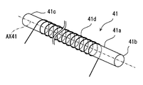
- the actuator element 41 has a material wire 41a, a fixed end 41b, an output end 41c, and a heating wire 41d.
- the material wire 41a is the above-described polymer fiber.
- the heating wire 41 d is also a part of the energy increasing / decreasing device 71.
- the heating wire 41d is also an energy transmission component for increasing or decreasing the energy of the material wire 41a.
- the heating wire 41d is disposed directly or indirectly on the surface of the material wire 41a.
- the heating wire 41d has a spiral shape or a coil shape.
- the heating wire 41d is a metal wire that generates heat when energized.
- the heating wire 41d can be provided by a platinum wire, a copper wire, or the like.
- the heating wire 41d is provided by a nichrome wire.
- the heating wire 41d can be provided by a round wire, a square wire, or a metal foil.
- the heating wire 41d is affixed to the surface of the material wire 41a.
- the heating wire 41d generates heat when energized.
- the heat supplied by the heating wire 41d is transmitted to the material wire 41a, and raises the temperature of the material wire 41a.
- the heating wire 41d stops generating heat when energization is interrupted.
- the heat of the material wire 41a is radiated to the external environment.
- the third coupling mechanism 31a and the guide mechanism 5 at the output end 41c contribute to heat dissipation. For this reason, a large temperature difference can be realized in the actuator element 41.
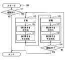
- control process 180 for swinging the driven body 31 is illustrated.
- the control process 180 is a part of the control process in the control device 70.
- step 181 it is determined whether the swing of the movable device 1 is required (ON) or not (OFF). For example, when it is required to operate a scanning infrared sensor, the swing is turned on. When it is not required to operate the scanning infrared sensor, the swing is turned off. If the swing is OFF, the control is terminated. If the swing is ON, the process proceeds to a loop process in steps 182 and 183.
- Step 182 is a process for heating the first actuator element 41.
- Step 183 is a process for heating the second actuator element 42. By alternately repeating Step 182 and Step 183, the driven body 31 operates in a swinging manner.
- step 184 it is determined whether the swing of the movable device 1 is required (ON) or not (OFF).
- Step 182 is a process of rotating the driven body 31 in the forward rotation direction.
- the forward rotation direction is a direction in which the driven body 31 is rotated in the clockwise direction when viewed from the first actuator element 41.
- Step 182 includes step 185 and step 186.
- step 185 first, the first actuator element 41 is activated.
- step 185 the heating wire 41d of the first actuator element 41 is energized.
- the control device 70 energizes the heating wire 41d from the energy increasing / decreasing device 71.
- the process of step 185 is executed so that the first actuator element 41 outputs a twist of a predetermined angle in the forward rotation direction.
- the rotation angle of the driven body 31 is detected by the rotation angle sensor, and step 185 is continued until a predetermined angle of rotation is obtained.
- the process of step 185 may be continued for a predetermined time by a timer process.
- step 186 the first actuator element 41 is inactivated.
- step 186 energization to the heating wire 41d of the first actuator element 41 is cut off.
- the control device 70 cuts off the power supply from the energy increasing / decreasing device 71 to the heating wire 41d.
- step 187 first, the second actuator element 42 is activated.
- step 187 the heating wire of the second actuator element 42 is energized.
- the control device 70 energizes the heating wire from the energy increasing / decreasing device 72.
- step 188 the second actuator element 42 is deactivated.
- step 188 energization to the heat generating wire of the second actuator element 42 is cut off.
- the control device 70 cuts off the power supply from the energy increasing / decreasing device 72 to the heating wire.
- activation corresponds to energization to the heating wire 41d.
- Inactivation corresponds to the interruption of energization to the heating wire 41d.
- Activation and deactivation word pairs can be associated with heating and heat dissipation word pairs, energization and deactivation word pairs, and active and standby word pairs.
- the control device 70 controls the energy increasing / decreasing device 71 so as to alternately repeat a period in which the energy of the actuator element 41 increases and a period in which the energy of the actuator element 41 decreases.
- the two actuator elements 41 and 42 are actively driven alternately.
- the first actuator element 41 actively outputs a torsional deformation in the forward rotation direction
- the second actuator element 42 is passively driven in the forward rotation direction.
- the second actuator element 42 is actively outputting torsional deformation in the reverse rotation direction
- the first actuator element 41 is passively driven in the reverse rotation direction. Since two actuator elements 41, 42 are used and are driven alternately, a stable rotational output is obtained in both directions.
- the quiet movable device 1 can be provided. This is particularly advantageous when the movable device 1 is used in a device installed indoors. For example, a quiet scanning infrared sensor can be obtained. Since the movable device 1 includes the guide mechanism 5, vibration of the driven body 31 is suppressed. In particular, vibrations in the direction intersecting the rotation axis AXR, that is, the vertical direction and the horizontal direction with respect to the rotation axis AXR are suppressed. Since the guide mechanism 5 defines a rotation axis AXR that is coaxial with the actuator axis AX41, the torsional deformation of the actuator element 41 can be directly taken out. Further, the guide mechanism 5 contributes to heat dissipation of the actuator element 41.
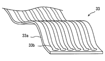
- FIG. 5 shows an FPC as an example of the connection member 33.
- the connection member 33 includes a resin layer 33a as a base material and a conductive wire 33b.
- the resin layer 33a is formed in a ribbon shape.
- the conductive wire 33b is provided by a copper foil formed on the resin layer 33a.
- the copper foil has a land portion for connection to the element 32 or the base 2.
- the connecting member 33 can be bent due to its thin shape. Further, the connecting member 33 can be attached to the initial shape.
- the connecting member 33 generates an urging force so as to return to the initial shape according to the deformation amount from the initial shape.
- FIG. 6 shows a cross section taken along line VI-VI in FIG.
- the element 32 has a terminal portion 32a having a plurality of terminals for electrical connection.
- the terminal portion 32 a is provided on the lower surface of the element 32.
- the connection member 33 extends from the base 2.
- the state in which the driven body 31 is in the neutral position is indicated by a solid line.
- a state where the driven body 31 is rotated in the direction of the arrow M42 is indicated by a broken line.
- This state is also a state in which the terminal portion 32 a is farthest from the connection portion between the base 2 and the connection member 33.
- a state in which the driven body 31 is rotated in the direction of the arrow M41 is indicated by a one-dot chain line.
- This state is also a state in which the terminal portion 32 a is closest to the connection portion between the base 2 and the connection member 33.
- the connecting member 33 is connected to the terminal portion 32a.
- the connection member 33 is wound over 3/4 circumference.
- the connecting member 33 is wound around the actuator element 42 and the driven body 31 between the base 2 and the terminal portion 32a.
- the connecting member 33 with winding has little change in elastic force even if the amount of winding changes. For this reason, the connecting member 33 contributes to reducing the load applied to the actuator elements 41 and 42 through the element 32 and the driven body 31.
- the connection member 33 has a state illustrated by a solid line as an initial state.
- the connecting member 33 moves between a state illustrated by a broken line and a state illustrated by a one-dot chain line.
- the connecting member 33 moves to both sides around the state illustrated by the solid line.
- the connection member 33 is attached with the center of the rotation angle VRS as an initial state. For this reason, the absolute value of the elastic force is small over the entire rotation angle VRS. For this reason, the connecting member 33 contributes to reducing the load applied to the actuator elements 41 and 42 through the element 32 and the driven body 31.
- the connecting member 33 maintains the winding direction throughout the movement.
- the connecting member 33 maintains the clockwise winding direction over the entire region. Therefore, there is no transient fluctuation that reverses the winding direction. Thereby, the transient fluctuation of the load given to actuator elements 41 and 42 is controlled.
- connection member 33 wound counterclockwise as viewed from the actuator element 41 is used.
- a connection member 234 wound clockwise is used.
- connection member 234 is wound clockwise when viewed from the actuator element 41. Also in this embodiment, it is possible to obtain the same effect as the preceding embodiment.
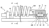
- connection members 33 and 234 are wound over 3/4 circumference. Instead, in this embodiment, a connection member 334 wound over one round or more is used.
- connection member 334 is wound over one turn or more.
- the connection member 334 is wound over a plurality of circumferences.
- the connection member 334 is wound around the actuator element 42.
- the connection member 334 is spirally wound so as to extend along the actuator axis AX42.
- FIG. 9 shows a cross section taken along line IX-IX.
- the spiral connection member 334 allows tightening (broken line) and loosening (dashed line) at the end connected to the terminal portion 32a.
- the spiral connection member 334 allows the end portion to be displaced by a plurality of turns.
- connection member 334 a change in urging force caused by the connection member 334 is suppressed.
- the possibility that the winding of the connecting member 334 is reversed can be reduced.
- connection members 33 and 234 are wound in the spiral shape over 3/4 circumference.
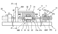
- connection member 434 is wound in a spiral shape of one or more rounds.
- the movable device 1 has a connection member 434.
- FIG. 11 shows a cross section taken along line XI-XI.
- the connection member 434 is wound over one turn + 3/4 turn in the initial state.
- the connection member 434 has a spiral shape.
- the connecting member 434 has no component extending along the actuator axis AX42. Also in this embodiment, the connection member 434 contributes to suppressing a change in urging force applied to the actuator elements 41 and 42.
- connection member 33, 234, 334, 434 is provided.
- at least two connecting members 33 and 234 are provided.
- the plurality of connecting members 33 and 234 are wound in opposite directions around the actuator axis to cancel each other's biasing force.
- the connecting member 33 and the connecting member 234 give urging forces in opposite directions to the driven body 31. Thereby, the connection member 33 and the connection member 234 cancel each other's elastic force.
- the number of connecting members in the reverse direction is not limited to two.
- the movable device 1 may include a plurality of connection members such as three or four. Two connecting members and one connecting member may be in a reverse relationship. In this embodiment, the urging
- the elastic member 661 is a metal coil spring.
- the elastic member 661 applies a counterclockwise force to the driven body 31 by being pulled from the free state.
- the elastic member 661 uses one end of the rotation range M631 of the driven body 31 as a reference position.
- the elastic member 661 is arranged to be pulled by the torsional motion of the actuator element 41.
- the elastic member 661 applies a return force against the rotational force in the direction of the arrow M41.
- the movable device 1 includes a connection member 33.
- the connecting member 33 is wound around 3 ⁇ 4 circumference around the extension line of the rotation axis AXR.
- the reciprocating motion of the driven body 31 can be obtained by one actuator element 41.
- the connection member 33 can be used as a part of the return mechanism 622. That is, the elastic member 661 can be assisted using the elastic force of the connecting member 33.
- the connecting member 33 when the connecting member 33 generates an elastic force that further increases the winding force, a biasing force in a direction opposite to the arrow M41 is applied to the driven body 31.
- an urging force in the same direction as the arrow M41 is applied to the driven body 31.
- the driven body 31 is stabilized.
- the configuration of this embodiment can also be used in other preceding embodiments.
- the disclosure in this specification is not limited to the illustrated embodiments.
- the disclosure encompasses the illustrated embodiments and variations by those skilled in the art based thereon.
- the disclosure is not limited to the combinations of parts and / or elements shown in the embodiments.
- the disclosure can be implemented in various combinations.
- the disclosure may have additional parts that can be added to the embodiments.
- the disclosure includes those in which parts and / or elements of the embodiments are omitted.
- the disclosure encompasses the replacement or combination of parts and / or elements between one embodiment and another.
- the technical scope disclosed is not limited to the description of the embodiments.
- the guide mechanism 5 is provided by the shaft 51 and the guide bore 52.
- the shaft 51 and the guide bore 52 provide a so-called bearing mechanism.
- the bearing mechanism that provides the guide mechanism 5 can be provided by many mechanisms such as a ball bearing, a fluid bearing, and a magnetic bearing in addition to the sliding bearing as in the embodiment.
- a relatively simple and lightweight sliding bearing is employed.
- the separate shaft 51 is fixed to the driven body 31.
- the shaft may be formed integrally with the driven body 31 or the support portion 23.
- a cylindrical portion in place of the shaft 51 can be formed on the driven body 31 or the support portion 23 by machining.
- a cylindrical portion instead of the shaft 51 may be insert-molded on the driven body 31 or the support portion 23.
- the movable device 1 includes a guide mechanism 5.
- the driven body 31 may be supported by the actuator elements 41 and 42 and the connection member without providing the guide mechanism 5.
- the winding-shaped connecting member enables the driven body 31 to be stably rotated.
- the guide mechanism 5 includes a shaft 51 and a guide bore 52. Instead, a guide mechanism that suspends the driven body like a pendulum, or a guide mechanism that supports the driven body at a fulcrum like an inverted pendulum may be adopted.
- the fixing unit may be provided with a mechanism that mechanically limits the rotation direction.
- a ratchet mechanism can be provided in the fixing portion.
- the ratchet mechanism fixes the fixed end 41b.
- the fixed end 41b rotates in the direction of the arrow M41
- the fixed end 41b is opened.
- the ratchet mechanism is in a fixed state to allow active deformation, and is in an open state to negate passive deformation.
- the fixing force at the fixed end 41b or the output end 41c may be variable.
- the fixing force by the fixing portions 21 and 22 may be changed between an open state and a fixed state, or strength.
- the coupling mechanism 21d may be switched between a state in which it is strongly tightened on the outer peripheral surface of the end sleeve 21a and a state in which it is weakly pressed against the outer peripheral surface of the end sleeve 21a. In this case, the end sleeve 21a rotates while rubbing against the set screw.
- the heating wire 41d is directly wound around the material wire 41a.
- a member may be disposed between the material wire 41a and the heating wire 41d.
- a support member that is electrically insulating and has excellent thermal conductivity can be disposed.
- the support member can be provided by insulating paper wound around the material wire 41a or a glass tube that accommodates the material wire 41a therein.
- the heating wire 41d is in direct contact with the material wire 41a, but in another embodiment, the heating wire 41d is wound without being in direct contact with the material wire 41a.
- a heat generating member may be disposed on the inner surface of the support member.
- the actuator element 41 includes a bobbin 741s.
- the energy transmission component can be supported in a reciprocating manner without the bobbin 741s.
- the heating wire 741d itself may be fixed to the fixing portion 21. Further, the heating wire 741d may be disposed on the inner surface of the bobbin 741s.
- the connecting members 33, 234, 334, 434 are provided by the FPC.
- the electrical connection may be provided by a strip-shaped electric wire including a plurality of electric wires, a flat multi-core electric wire, or a plurality of independent covered electric wires. Also in these cases, the electric wire is used in a wound shape.
- the energy of the material wire 41a is increased or decreased by heating with the heating wire 41d and heat radiation.
- the energy of the material wire 41a can be increased or decreased by cooling with the cooling device and cooling.
- the Peltier effect element can be disposed along the material line 41a. The Peltier effect element provides an energy transfer component. In this case, when the material wire 41a is cooled, the material wire 41a is thermally expanded or contracted to cause torsion deformation.
- a nichrome wire is used as the heating wire 41d.
- the energy transmission component can be provided by various electric heating members.
- the heat generating member may be provided by a conductive thin film called a conductive polymer or a conductive metal film.
- the film is formed on the surface of the material wire 41a.
- the conductive polymer or the conductive metal film is formed on the surface of the material wire 41a by various methods such as plating, synthesis, and sputtering.
- the shape is a spiral wound around the material wire 41a.
- a spiral heat-generating member may be formed by winding a ribbon-like conductive polymer or conductive metal film formed separately from the material wire 41a and disposed outside the material wire 41a.
Abstract
This movable device is provided with: actuator elements (41, 42) that deform as a result of an increase or decrease in energy; a driven body (31) that is driven by the deformation of the actuator elements; a fixed base (2); and a connecting member (33, 234, 334, 434) that has a wound shape, connects the base with the driven body, and maintains the winding direction thereof while deforming in a direction causing loosening of the winding thereof and in a direction causing tightening of the winding thereof as a result of displacement of the driven body. As a result, it is possible to suppress transitional changes in the load applied to the actuator elements.
Description
本出願は、当該開示内容が参照によって本出願に組み込まれた、2017年3月23日に出願された日本特許出願2017-057945号を基にしている。
This application is based on Japanese Patent Application No. 2017-057945 filed on Mar. 23, 2017, the disclosure of which is incorporated herein by reference.
この明細書における開示は、アクチュエータ素子の変形を利用する可動装置に関する。
The disclosure in this specification relates to a movable device that utilizes deformation of an actuator element.
特許文献1は、アクチュエータ素子の変形を利用する可動装置を開示する。この技術では、被駆動体を機械的に移動させるために、部材の変形を直接または間接に利用している。アクチュエータ素子のひとつの例は、細長い合成繊維である。
Patent Document 1 discloses a movable device that utilizes deformation of an actuator element. In this technique, the deformation of the member is directly or indirectly used to mechanically move the driven body. One example of an actuator element is an elongated synthetic fiber.
従来技術には、被駆動体である機器、または被駆動体に搭載された機器との電気的な接続装置について十分な開示がない。接続装置には、アクチュエータ素子に与える負荷変動を抑制することが求められる。別の観点では、アクチュエータ素子に与える負荷の過渡的な変動を抑制することが求められる。これらの要請は、アクチュエータ素子による駆動力が弱くなるほど、強く求められる。上述の観点において、または言及されていない他の観点において、可動装置にはさらなる改良が求められている。
The prior art does not sufficiently disclose a device that is a driven body or an electrical connection device with a device mounted on the driven body. The connecting device is required to suppress the load fluctuation applied to the actuator element. From another viewpoint, it is required to suppress a transient change in the load applied to the actuator element. These requests are strongly demanded as the driving force by the actuator element becomes weaker. In view of the above or other aspects not mentioned, there is a need for further improvements in mobile devices.
開示されるひとつの目的は、アクチュエータ素子に与える負荷が小さく、負荷の過渡的な変動を抑制した可動装置を提供することである。
One disclosed object is to provide a movable device in which a load applied to an actuator element is small and a transient change of the load is suppressed.
ここに開示された可動装置は、エネルギの増減によって変形を生じるアクチュエータ素子と、アクチュエータ素子の変形によって駆動される被駆動体と、固定の基台と、基台と被駆動体との間を接続しており、被駆動体の変位によって、巻き方向を維持しながら、巻きを緩める方向と巻きを締める方向とに変形する巻き形状の接続部材とを備える。
The movable device disclosed here connects an actuator element that is deformed by increasing or decreasing energy, a driven body that is driven by the deformation of the actuator element, a fixed base, and a base and a driven body. And a winding-shaped connecting member that is deformed in a direction of loosening the winding and a direction of tightening the winding while maintaining the winding direction by displacement of the driven body.
開示される可動装置によると、基台と被駆動体との間が接続部材によって接続されている。接続部材は、巻き形状である。巻き形状は、被駆動体が変位すると、巻きを緩める方向と巻きを締める方向とに変形する。巻き形状の接続部材は、被駆動体、ひいてはアクチュエータ素子に付勢力を付与する場合がある。ただし、巻き形状に起因する付勢力は抑制される。しかも、巻き形状は、被駆動体が変位しても、巻き方向を維持する。このため、付勢力の過渡的な変化が抑制される。
According to the disclosed movable device, the base and the driven body are connected by the connecting member. The connecting member has a wound shape. When the driven body is displaced, the winding shape is deformed into a direction of loosening the winding and a direction of tightening the winding. The winding-shaped connecting member may give a biasing force to the driven body, and thus the actuator element. However, the urging force resulting from the winding shape is suppressed. Moreover, the winding shape maintains the winding direction even when the driven body is displaced. For this reason, the transitional change of urging | biasing force is suppressed.
図面を参照しながら、複数の実施形態を説明する。複数の実施形態において、機能的におよび/または構造的に対応する部分および/または関連付けられる部分には同一の参照符号、または百以上の位が異なる参照符号が付される場合がある。対応する部分および/または関連付けられる部分については、他の実施形態の説明を参照することができる。
A plurality of embodiments will be described with reference to the drawings. In embodiments, functionally and / or structurally corresponding parts and / or associated parts may be assigned the same reference signs or reference signs that differ by more than a hundred. For the corresponding parts and / or associated parts, the description of other embodiments can be referred to.
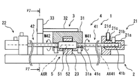
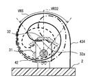
図1において、可動装置1は、固定の基台2と、基台2に対して機械的に動くことができる可動部3とを有する。可動部3は、高さ方向HDに沿って延びる回動軸AXRの周りを回転移動することができる。可動部3は、回動軸AXRの周りの所定の角度範囲RGを往復移動する。可動部3は、被駆動体31を有する。可動部3の動きは、揺動とも呼ばれる。なお、可動部3の移動方向は、回動に限られない。可動部3の移動方向は、例えば、高さ方向HDに沿う平行移動、幅方向WDに沿う平行移動、奥行き方向DDの周りにおける回転移動など多様な動きに適合可能である。
1, the movable device 1 includes a fixed base 2 and a movable portion 3 that can move mechanically with respect to the base 2. The movable part 3 can rotate around a rotation axis AXR extending along the height direction HD. The movable part 3 reciprocates a predetermined angular range RG around the rotation axis AXR. The movable part 3 has a driven body 31. The movement of the movable part 3 is also called rocking. In addition, the moving direction of the movable part 3 is not restricted to rotation. The moving direction of the movable part 3 can be adapted to various movements such as a parallel movement along the height direction HD, a parallel movement along the width direction WD, and a rotational movement around the depth direction DD.
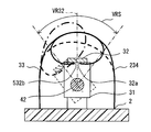
可動装置1は、被駆動体31に搭載された素子32を有する。素子32は、電気的な能動的作用、または電気的な受動的作用を提供する。素子32は、例えば、電気的な光源、電気的な送風機、電気的な熱源、電気的な電波源、電気的な磁力源である。素子32は、例えば、電気的なセンサ素子である。可動装置1は、電気的な接続のために、基台2と素子32とを電気的に接続する接続部材を備える場合がある。素子32は、主要な機能のための軸VR32を有する。軸VR32は、例えば、素子32が光源である場合には、光軸に相当する。軸VR32は、例えば、素子32がセンサである場合には、検出軸に相当する。軸VR32は、被駆動体31の回動によって振られる。軸VR32は、回動角VRSの範囲で振られる。
The movable device 1 has an element 32 mounted on the driven body 31. The element 32 provides an electrically active action or an electrically passive action. The element 32 is, for example, an electrical light source, an electrical blower, an electrical heat source, an electrical radio wave source, or an electrical magnetic source. The element 32 is, for example, an electrical sensor element. The movable device 1 may include a connection member that electrically connects the base 2 and the element 32 for electrical connection. The element 32 has an axis VR32 for the main function. For example, when the element 32 is a light source, the axis VR32 corresponds to the optical axis. For example, when the element 32 is a sensor, the axis VR32 corresponds to a detection axis. The shaft VR32 is swung by the rotation of the driven body 31. The axis VR32 is swung within the range of the rotation angle VRS.
可動装置1は、センサ装置でもある。素子32は、センサ素子である。素子32は、検出方向と検出範囲を示す軸VR32を有する。素子32は、軸VR32の方向における物理量を検出する。素子32は、例えば、画像センサ、赤外線センサ、超音波センサ、レーダアンテナ、電磁波センサ、放射線センサなど多様な素子によって提供される。この実施形態では、素子32は、室内に設置される赤外線センサである。素子32の検出信号は、有線または無線によって赤外線情報を利用する機器に供給される。赤外線情報は、例えば、空調装置に供給され、利用される。可動装置1は、住居、事務所、車両、船舶、航空機などの室内に設置され、室内の人に関連する情報を収集するために利用される。基台2は、これらの室内に定置されている。
The movable device 1 is also a sensor device. The element 32 is a sensor element. The element 32 has an axis VR32 indicating a detection direction and a detection range. The element 32 detects a physical quantity in the direction of the axis VR32. The element 32 is provided by various elements such as an image sensor, an infrared sensor, an ultrasonic sensor, a radar antenna, an electromagnetic wave sensor, and a radiation sensor. In this embodiment, the element 32 is an infrared sensor installed indoors. The detection signal of the element 32 is supplied to a device using infrared information by wire or wireless. Infrared information is supplied and used, for example, to an air conditioner. The movable device 1 is installed in a room such as a residence, an office, a vehicle, a ship, and an aircraft, and is used to collect information related to people in the room. The base 2 is placed in these rooms.
可動装置1は、軸VR32を振るように移動させる。可動装置1は、軸VR32を移動させるセンサ装置を提供する。軸VR32の移動は、指向方向可変型、追尾型、あるいは走査型といった多様なセンサ装置の提供を可能とする。この実施形態では、被駆動体31は、周期的に揺動するから、走査型のセンサ装置が提供されている。軸VR32は、回動軸AXRを中心に回動する。軸VR32は、幅方向WDと奥行き方向DDとに広がる平面に沿って、所定の回動角VRSの範囲内を移動可能である。この実施形態では、回動角VRSが走査範囲である。
The movable device 1 is moved so as to swing the axis VR32. The movable device 1 provides a sensor device that moves the axis VR32. The movement of the axis VR32 makes it possible to provide various sensor devices such as a directivity direction variable type, a tracking type, or a scanning type. In this embodiment, since the driven body 31 periodically swings, a scanning sensor device is provided. The axis VR32 rotates about the rotation axis AXR. The axis VR32 is movable within a range of a predetermined rotation angle VRS along a plane extending in the width direction WD and the depth direction DD. In this embodiment, the rotation angle VRS is the scanning range.
可動部3は、電気的な接続部材33を備える。接続部材33は、基台2と素子32との間を電気的に接続する。接続部材33は、基台2と被駆動体31との間を間接的に接続している。基台2の上には素子32のための回路が敷設されている。基台2の上には、外部接続のための機器が設置されていてもよい。接続部材33は、基台2と被駆動体31との間を電気的に接続してもよい。この場合、素子32の電線は、被駆動体31を経由して配置される。
The movable part 3 includes an electrical connection member 33. The connection member 33 electrically connects the base 2 and the element 32. The connection member 33 indirectly connects the base 2 and the driven body 31. A circuit for the element 32 is laid on the base 2. On the base 2, equipment for external connection may be installed. The connection member 33 may electrically connect the base 2 and the driven body 31. In this case, the electric wire of the element 32 is arranged via the driven body 31.
接続部材33は、撓むことができる可撓性部材である。接続部材33は、柔軟な板状の部材である。これにより、接続部材33は、それ自身が変形することにより、被駆動体31と素子32とが共に回動することを許容する。接続部材33は、主として弾性変形可能な弾性部材によって形成されている。接続部材33は、回動軸AXRと平行な面を有している。接続部材33は、いわゆるフレキシブルプリント配線板(FPC)によって提供されている。
The connecting member 33 is a flexible member that can be bent. The connection member 33 is a flexible plate-like member. As a result, the connecting member 33 allows the driven body 31 and the element 32 to rotate together by deforming itself. The connection member 33 is mainly formed of an elastic member that can be elastically deformed. The connection member 33 has a surface parallel to the rotation axis AXR. The connection member 33 is provided by a so-called flexible printed wiring board (FPC).
接続部材33は、巻き形状を有する。接続部材33は、回動軸AXRと平行な軸の周りにおいて巻かれている。接続部材33は、1/4周以上に巻かれている。接続部材33の巻きは、3/4周である。接続部材33の巻きは、3/4周以上でもよい。
The connecting member 33 has a winding shape. The connection member 33 is wound around an axis parallel to the rotation axis AXR. The connection member 33 is wound around 1/4 or more. The winding of the connection member 33 is 3/4 round. The winding of the connection member 33 may be 3/4 or more.
接続部材33は、被駆動体31の変位によって、巻きを緩める方向と巻きを締める方向とに変形する巻き形状である。接続部材33は、被駆動体31の変位があっても、巻き方向を維持する。接続部材33は、被駆動体31が回動角VRSにわたって移動しても、全体にわたって同一の巻き方向を維持する。接続部材33は、全体にわたって同一の巻き方向を維持するように配置されている。接続部材33は、素子32との接続部の移動範囲より外側において、部分的な環を描くように配置されている。
The connecting member 33 has a winding shape that is deformed in a direction to loosen the winding and a direction to tighten the winding by the displacement of the driven body 31. The connecting member 33 maintains the winding direction even when the driven body 31 is displaced. Even if the driven body 31 moves over the rotation angle VRS, the connection member 33 maintains the same winding direction throughout. The connecting member 33 is arranged so as to maintain the same winding direction throughout. The connection member 33 is arranged so as to draw a partial ring outside the movement range of the connection portion with the element 32.
接続部材33が、巻方向の反転を生じる場合、接続部材33に起因する付勢力が過渡的に大きく変動する。例えば、付勢力の方向の反転、付勢力のステップ的な変化、付勢力の不連続な変化、または付勢力の一時的な変化を生じる場合がある。このような付勢力の過渡的な変動は、被駆動体31の挙動を不安定にする。この実施形態では、接続部材33は、全体にわたって同一の巻方向を維持するから、付勢力の過渡的な変動が抑制される。
When the connecting member 33 is reversed in the winding direction, the urging force due to the connecting member 33 fluctuates greatly. For example, a reversal of the direction of the urging force, a stepwise change in the urging force, a discontinuous change in the urging force, or a temporary change in the urging force may occur. Such transient fluctuation of the urging force makes the behavior of the driven body 31 unstable. In this embodiment, since the connection member 33 maintains the same winding direction throughout, the transitional fluctuation of the urging force is suppressed.
可動装置1は、アクチュエータ機構4を備える。アクチュエータ機構4は、可動部3を回動させるための回転力を提供する。アクチュエータ機構4は、動力源でもある。アクチュエータ機構4は、往復するように回転力を提供する。
The movable device 1 includes an actuator mechanism 4. The actuator mechanism 4 provides a rotational force for rotating the movable part 3. The actuator mechanism 4 is also a power source. The actuator mechanism 4 provides a rotational force so as to reciprocate.
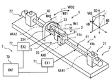
アクチュエータ機構4は、2つのアクチュエータ素子41、42を有する。2つのアクチュエータ素子41、42は、回動軸AXRの延長線上に配置されている。2つのアクチュエータ素子41、42は、被駆動体31の両側に配置されている。被駆動体31と、2つのアクチュエータ素子41、42とは、直列的に配置されている。図中では、アクチュエータ素子41、42は、やや太く強調されて図示されている。
The actuator mechanism 4 has two actuator elements 41 and 42. The two actuator elements 41 and 42 are arranged on an extension line of the rotation axis AXR. The two actuator elements 41 and 42 are arranged on both sides of the driven body 31. The driven body 31 and the two actuator elements 41 and 42 are arranged in series. In the figure, the actuator elements 41 and 42 are illustrated with a little emphasis.
第1のアクチュエータ素子41は、被駆動体31と、固定部21とに連結されている。第1のアクチュエータ素子41は、アクチュエータ軸AX41に沿って延びている。アクチュエータ軸AX41は、第1のアクチュエータ素子41の中心軸でもある。アクチュエータ軸AX41は、回動軸AXRの延長上に位置している。アクチュエータ軸AX41と回動軸AXRとは同軸である。
The first actuator element 41 is connected to the driven body 31 and the fixed portion 21. The first actuator element 41 extends along the actuator axis AX41. The actuator axis AX41 is also the central axis of the first actuator element 41. The actuator shaft AX41 is located on the extension of the rotation shaft AXR. The actuator shaft AX41 and the rotation shaft AXR are coaxial.
第2のアクチュエータ素子42は、被駆動体31と、固定部22とに連結されている。第2のアクチュエータ素子42は、アクチュエータ軸AX42に沿って延びている。アクチュエータ軸AX42は、第2のアクチュエータ素子42の中心軸でもある。アクチュエータ軸AX42は、回動軸AXRの延長上に位置している。アクチュエータ軸AX42と回動軸AXRとは同軸である。
The second actuator element 42 is connected to the driven body 31 and the fixed portion 22. The second actuator element 42 extends along the actuator axis AX42. The actuator axis AX42 is also the central axis of the second actuator element 42. The actuator shaft AX42 is located on the extension of the rotation shaft AXR. The actuator shaft AX42 and the rotation shaft AXR are coaxial.
被駆動体31は、基台2の中央部に配置されている。固定部21は、基台2の一端部に設けられている。固定部21は、基台2に固定されている。固定部22は、基台2の他端部に設けられている。固定部22は、基台2に固定されている。基台2は、アクチュエータ機構4が発生する力に対抗して、可動装置1の形状を維持できる材料で作られている。例えば、基台2は、金属製または樹脂製である。基台2の一部または全体は、プリント配線板によって提供されていてもよい。
The driven body 31 is disposed at the center of the base 2. The fixing portion 21 is provided at one end of the base 2. The fixing part 21 is fixed to the base 2. The fixing part 22 is provided at the other end of the base 2. The fixing part 22 is fixed to the base 2. The base 2 is made of a material that can maintain the shape of the movable device 1 against the force generated by the actuator mechanism 4. For example, the base 2 is made of metal or resin. Part or the whole of the base 2 may be provided by a printed wiring board.
第1のアクチュエータ素子41と、第2のアクチュエータ素子42とは、被駆動体31に対して対称的に配置されている。第1のアクチュエータ素子41と、第2のアクチュエータ素子42とは、対称的な構造を有する。以下の説明では、第1のアクチュエータ素子41について説明する。この説明は、第2のアクチュエータ素子42の説明として参照することができる。
The first actuator element 41 and the second actuator element 42 are arranged symmetrically with respect to the driven body 31. The first actuator element 41 and the second actuator element 42 have a symmetrical structure. In the following description, the first actuator element 41 will be described. This description can be referred to as a description of the second actuator element 42.
第1のアクチュエータ素子41は、固定部21に連結されうる固定端41bを有する。固定端41bは、少なくとも第1のアクチュエータ素子41が回動力を出力するときに固定部21に連結されている。第1のアクチュエータ素子41は、被駆動体31に連結されうる出力端41cを有する。出力端41cは、少なくとも第1のアクチュエータ素子41が回動力を出力するときに被駆動体31に連結されている。被駆動体31は、アクチュエータ軸AX41上においてアクチュエータ素子41と連結されている。なお、固定端41bおよび出力端41cの名称は、便宜的なものである。以下の説明では、固定端41bおよび出力端41cは、単に端部と呼ばれることがある。
The first actuator element 41 has a fixed end 41 b that can be connected to the fixed portion 21. The fixed end 41b is connected to the fixed portion 21 when at least the first actuator element 41 outputs rotational power. The first actuator element 41 has an output end 41 c that can be connected to the driven body 31. The output end 41c is connected to the driven body 31 when at least the first actuator element 41 outputs rotational power. The driven body 31 is connected to the actuator element 41 on the actuator shaft AX41. The names of the fixed end 41b and the output end 41c are for convenience. In the following description, the fixed end 41b and the output end 41c may be simply referred to as ends.
第1のアクチュエータ素子41は、棒状である。第1のアクチュエータ素子41は、細長い棒状または繊維状と呼べる形状である。第1のアクチュエータ素子41は、円柱状または円筒状に形成することができる。
The first actuator element 41 has a rod shape. The first actuator element 41 has a shape that can be called an elongated rod shape or a fiber shape. The first actuator element 41 can be formed in a columnar shape or a cylindrical shape.
可動装置1は、可動部3の動きを案内するための案内機構5を有する。案内機構5は、基台2に設けられた支持部23と、被駆動体31との間に設けられている。支持部23は、基台2に固定されている。案内機構5は、高さ方向HDの周りにおける被駆動体31の回転運動を許容する。案内機構5は、奥行き方向DDの周りにおける回転運動、および幅方向WDの周りにおける回転運動を抑制する。案内機構5は、被駆動体31の移動のうち、奥行き方向DDへの上下運動、および幅方向WDへの左右運動を抑制する。案内機構5は、高さ方向HDへの前後運動を抑制してもよい。案内機構5は、高さ方向HDへの前後運動を許容する場合がある。
The movable device 1 has a guide mechanism 5 for guiding the movement of the movable part 3. The guide mechanism 5 is provided between the support portion 23 provided on the base 2 and the driven body 31. The support part 23 is fixed to the base 2. The guide mechanism 5 allows the rotational movement of the driven body 31 around the height direction HD. The guide mechanism 5 suppresses the rotational motion around the depth direction DD and the rotational motion around the width direction WD. The guide mechanism 5 suppresses the vertical movement in the depth direction DD and the horizontal movement in the width direction WD of the movement of the driven body 31. The guide mechanism 5 may suppress the back-and-forth movement in the height direction HD. The guide mechanism 5 may allow back-and-forth movement in the height direction HD.
高さ方向HDをロール軸、幅方向WDをピッチング軸、および奥行き方向DDをヨー軸と定義することができる。この場合、案内機構5は、被駆動体31のロール運動を許容する。案内機構5は、利用可能な範囲を超えるような過剰なロール運動を抑制してもよい。例えば、被駆動体31と支持部23との直接的な衝突、または弾性部材を介した間接的な衝突は、ロール運動範囲を制限する。案内機構5は、被駆動体31のヨーイング運動、およびピッチング運動を抑制する。また、案内機構5は、被駆動体31の上下運動、および左右運動を抑制する。案内機構5は、被駆動体31の前後運動を抑制してもよい。案内機構5は、被駆動体31の前後運動を許容する場合がある。
The height direction HD can be defined as the roll axis, the width direction WD as the pitching axis, and the depth direction DD as the yaw axis. In this case, the guide mechanism 5 allows the driven body 31 to roll. The guide mechanism 5 may suppress excessive roll movement exceeding the available range. For example, a direct collision between the driven body 31 and the support portion 23 or an indirect collision via an elastic member limits the roll motion range. The guide mechanism 5 suppresses yawing motion and pitching motion of the driven body 31. Further, the guide mechanism 5 suppresses the vertical and horizontal movements of the driven body 31. The guide mechanism 5 may suppress the back-and-forth movement of the driven body 31. The guide mechanism 5 may allow the back-and-forth movement of the driven body 31 in some cases.
可動装置1は、制御システム7を備える。制御システム7は、制御装置(CNT)70と、エネルギ増減装置(EX1、EX2)71、72を有する。エネルギ増減装置71、72は、2つのアクチュエータ素子41、42から機械的な運動を取り出すために、2つのアクチュエータ素子41、42のエネルギを増減させる装置である。2つのアクチュエータ素子41、42を回転させるように、エネルギ増減装置71、72は2つのアクチュエータ素子41、42のエネルギを増減させる。
The movable device 1 includes a control system 7. The control system 7 includes a control device (CNT) 70 and energy increase / decrease devices (EX1, EX2) 71, 72. The energy increasing / decreasing devices 71, 72 are devices that increase / decrease the energy of the two actuator elements 41, 42 in order to extract mechanical motion from the two actuator elements 41, 42. The energy increasing / decreasing devices 71 and 72 increase or decrease the energy of the two actuator elements 41 and 42 so as to rotate the two actuator elements 41 and 42.
制御装置は、少なくともひとつの演算処理装置(CPU)と、プログラムとデータとを記憶する記憶媒体としての少なくともひとつのメモリ装置とを有する。制御装置は、コンピュータによって読み取り可能な記憶媒体を備えるマイクロコンピュータによって提供される。記憶媒体は、コンピュータによって読み取り可能なプログラムを非一時的に格納する非遷移的実体的記憶媒体である。記憶媒体は、半導体メモリまたは磁気ディスクなどによって提供されうる。制御装置は、ひとつのコンピュータ、またはデータ通信装置によってリンクされた一組のコンピュータ資源によって提供されうる。プログラムは、制御装置によって実行されることによって、制御装置をこの明細書に記載される装置として機能させ、この明細書に記載される方法を実行するように制御装置を機能させる。
The control device has at least one arithmetic processing unit (CPU) and at least one memory device as a storage medium for storing programs and data. The control device is provided by a microcomputer including a computer-readable storage medium. The storage medium is a non-transitional tangible storage medium that stores a computer-readable program in a non-temporary manner. The storage medium can be provided by a semiconductor memory or a magnetic disk. The controller can be provided by a computer or a set of computer resources linked by a data communication device. The program is executed by the control device to cause the control device to function as the device described in this specification and to cause the control device to perform the method described in this specification.
制御システムは、制御装置に入力される情報を示す信号を供給する複数の信号源を入力装置として有する。制御システムは、制御装置が情報をメモリ装置に格納することにより、情報を取得する。制御システムは、制御装置によって挙動が制御される複数の制御対象物を出力装置として有する。制御システムは、メモリ装置に格納された情報を信号に変換して制御対象物に供給することにより制御対象物の挙動を制御する。例えば、制御装置は、外部から作動信号と、停止信号とを取得し、エネルギ増減装置71、72を間欠的に活性化することにより、可動装置1に揺動的に運動させる。
The control system has a plurality of signal sources that supply signals indicating information input to the control device as input devices. The control system acquires information by the control device storing the information in the memory device. The control system has a plurality of control objects whose behavior is controlled by the control device as output devices. The control system controls the behavior of the control object by converting information stored in the memory device into a signal and supplying the signal to the control object. For example, the control device acquires an operation signal and a stop signal from the outside, and intermittently activates the energy increasing / decreasing devices 71 and 72 to cause the movable device 1 to swing.
制御システムに含まれる制御装置と信号源と制御対象物とは、多様な要素を提供する。それらの要素の少なくとも一部は、機能を実行するためのブロックと呼ぶことができる。別の観点では、それらの要素の少なくとも一部は、構成として解釈されるモジュール、またはセクションと呼ぶことができる。さらに、制御システムに含まれる要素は、意図的な場合にのみ、その機能を実現する手段ともよぶことができる。
The control device, signal source, and control object included in the control system provide various elements. At least some of these elements can be referred to as blocks for performing functions. In another aspect, at least some of these elements can be referred to as modules or sections that are interpreted as configurations. Furthermore, the elements included in the control system can also be referred to as means for realizing the functions only when intentional.
制御システムが提供する手段および/または機能は、実体的なメモリ装置に記録されたソフトウェアおよびそれを実行するコンピュータ、ソフトウェアのみ、ハードウェアのみ、あるいはそれらの組合せによって提供することができる。例えば、制御装置がハードウェアである電子回路によって提供される場合、それは多数の論理回路を含むデジタル回路、またはアナログ回路によって提供することができる。
The means and / or function provided by the control system can be provided by software recorded in a substantial memory device and a computer that executes the software, software only, hardware only, or a combination thereof. For example, if the controller is provided by an electronic circuit that is hardware, it can be provided by a digital circuit including a number of logic circuits, or an analog circuit.
2つのアクチュエータ素子41、42は、ひとつの方向へ向けて能動的な変形を生じる。2つのアクチュエータ素子41、42の変形方向は、逆方向、すなわち対称的な方向である。2つのアクチュエータ素子41、42の利用により、両方向、すなわち往復的な方向に向けて能動的な変形が得られる。
The two actuator elements 41 and 42 are actively deformed in one direction. The deformation directions of the two actuator elements 41 and 42 are opposite directions, that is, symmetrical directions. By using the two actuator elements 41, 42, an active deformation is obtained in both directions, i.e. in a reciprocating direction.
アクチュエータ素子41、42は、熱エネルギの増減によってアクチュエータ軸AX41、AX42周りの変形を生じる。第1のアクチュエータ素子41は、第1のアクチュエータ素子41の温度が上昇すると、ねじれるように変形する。固定端41bが固定部21によって固定されているから、被駆動体31は、第1の方向である矢印M41の方向へ回動する。第2のアクチュエータ素子42は、第2のアクチュエータ素子42の温度が上昇すると、ねじれるように変形する。固定端42bが固定部22によって固定されているから、被駆動体31は、第2の方向である矢印M42の方向へ回動する。矢印M41の方向と矢印M42の方向とは、被駆動体31に対して対称的である。この結果、被駆動体31は、矢印M31で図示される角度範囲にわたって回動する。矢印M31は、軸VR32の回動角VRSに対応している。
Actuator elements 41 and 42 are deformed around actuator axes AX41 and AX42 by increasing or decreasing thermal energy. The first actuator element 41 is deformed so as to be twisted when the temperature of the first actuator element 41 rises. Since the fixed end 41b is fixed by the fixing portion 21, the driven body 31 rotates in the direction of the arrow M41 that is the first direction. The second actuator element 42 is deformed so as to be twisted when the temperature of the second actuator element 42 rises. Since the fixed end 42b is fixed by the fixing portion 22, the driven body 31 rotates in the direction of the arrow M42 that is the second direction. The direction of the arrow M41 and the direction of the arrow M42 are symmetric with respect to the driven body 31. As a result, the driven body 31 rotates over the angular range indicated by the arrow M31. The arrow M31 corresponds to the rotation angle VRS of the axis VR32.
この実施形態に利用可能なアクチュエータ素子41、42と、エネルギ増減装置71、72とは、特開2016-42783号公報に記載のものを含む。特開2016-42783号公報の記載内容は、この明細書における技術的要素の説明として、参照により援用される。アクチュエータ素子41、42は、人工筋肉と呼ばれる多様な材料によって提供することができる。例えば、合成樹脂、金属、形状記憶合金、および有機物といった材料を利用可能である。
The actuator elements 41 and 42 and the energy increasing / decreasing devices 71 and 72 that can be used in this embodiment include those described in JP-A-2016-42783. The content described in Japanese Patent Application Laid-Open No. 2016-42783 is incorporated by reference as an explanation of technical elements in this specification. The actuator elements 41 and 42 can be provided by various materials called artificial muscles. For example, materials such as synthetic resins, metals, shape memory alloys, and organic materials can be used.
アクチュエータ素子41、42のひとつの例は、合成繊維である。合成繊維は、回動軸AXRの延長線上に沿って延びている。合成繊維は、細長い。合成繊維は、ポリマ繊維と呼ばれる。ポリマ繊維の典型的なひとつの例は、モノフィラメント樹脂である。モノフィラメント樹脂は、ポリアミド系樹脂、およびポリエチレン系樹脂を含む。例えば、ナイロン、またはポリチレンと呼ばれるポリマ繊維は、温度変化に対するねじり変形量を有する場合があり、アクチュエータ素子41、42として利用可能である。
One example of the actuator elements 41 and 42 is a synthetic fiber. The synthetic fiber extends along an extension line of the rotation axis AXR. Synthetic fibers are elongated. Synthetic fibers are called polymer fibers. One typical example of a polymer fiber is a monofilament resin. The monofilament resin includes a polyamide resin and a polyethylene resin. For example, a polymer fiber called nylon or polyethylene may have a torsional deformation amount with respect to a temperature change, and can be used as the actuator elements 41 and 42.
ポリマ繊維を形成する高分子は、アクチュエータ軸AX41、AX42に沿って延びるように配向されている。高分子は、アクチュエータ軸AX41、AX42の周りに「撚り」を有する場合がある。「撚り」の語は、単繊維の中における撚りを指す場合と、複数繊維の間における撚りを指す場合とがある。ポリマ繊維の温度変化に対するねじり変形量は、単繊維の中における「撚り」の方向に沿って強く表れる場合がある。この実施形態では、アクチュエータ素子41、42は、単繊維である。別の形態では、ポリマ繊維の温度変化に対するねじり変形量は、複数繊維の間における「撚り」の方向に沿って表れる場合がある。アクチュエータ素子41、42は、互いに撚られた複数のポリマ繊維の束でもよい。
The polymer forming the polymer fiber is oriented so as to extend along the actuator axes AX41 and AX42. The polymer may have a “twist” around the actuator axes AX41, AX42. The term “twist” may refer to a twist in a single fiber and may refer to a twist between multiple fibers. The twist deformation amount with respect to the temperature change of the polymer fiber may appear strongly along the direction of “twist” in the single fiber. In this embodiment, the actuator elements 41 and 42 are single fibers. In another form, the amount of torsional deformation with respect to temperature change of the polymer fiber may appear along the direction of “twist” between the plurality of fibers. The actuator elements 41 and 42 may be a bundle of a plurality of polymer fibers twisted together.
アクチュエータ素子41、42のひとつの例は、形状記憶合金である。アクチュエータ軸AX41、AX42に沿って延びる形状記憶合金を利用可能である。形状記憶合金は、単一の棒状、およびコイル状に巻かれた形状など多様な形状によって利用可能である。形状記憶合金の形状は、温度変化に対するねじり変形量を得られるように選択される。
One example of the actuator elements 41 and 42 is a shape memory alloy. Shape memory alloys extending along the actuator axes AX41, AX42 can be used. The shape memory alloy can be used in various shapes such as a single rod shape and a coiled shape. The shape of the shape memory alloy is selected so as to obtain a torsional deformation amount with respect to a temperature change.
エネルギ増減装置71、72は、アクチュエータ素子41、42のエネルギ状態を高エネルギ状態と低エネルギ状態との間で双方向に変化させる。エネルギ増減装置71、72は、電気的に、光学的に、磁気的に、電磁波的に、あるいは放射線的にエネルギを付与し、除去することができる。電気的なエネルギの付与と除去とは、電気的な熱の増減、電流の増減、電界の増減、あるいは電荷の増減などを含む。例えば、アクチュエータ素子41、42のエネルギ状態が温度で示される場合、光の付与によって温度を増加させ、光の遮断によって温度を低下させることができる。
The energy increase / decrease devices 71 and 72 change the energy state of the actuator elements 41 and 42 bidirectionally between the high energy state and the low energy state. The energy increasing / decreasing devices 71 and 72 can apply and remove energy electrically, optically, magnetically, electromagnetically, or radiationally. The application and removal of electrical energy includes an increase or decrease in electrical heat, an increase or decrease in current, an increase or decrease in electric field, or an increase or decrease in charge. For example, when the energy state of the actuator elements 41 and 42 is indicated by temperature, the temperature can be increased by applying light, and the temperature can be decreased by blocking light.
エネルギの付与と、除去とは、直接的に、または間接的に行うことができる。例えば、アクチュエータ素子41、42に直接的に接触するエネルギ伝達部品によってエネルギを付与してもよいし、またはアクチュエータ素子41、42から離れて設置されたエネルギ伝達部品によって間接的にエネルギを付与してもよい。エネルギ伝達部品は、例えば、電気的な発熱部材によって提供できる。
Energy application and removal can be performed directly or indirectly. For example, energy may be applied by an energy transmission component that directly contacts the actuator elements 41 and 42, or energy may be indirectly applied by an energy transmission component installed away from the actuator elements 41 and 42. Also good. The energy transmission component can be provided by, for example, an electrical heating member.
例えば、アクチュエータ素子41、42を能動的に回転させるために、エネルギ増減装置71、72は、アクチュエータ素子41、42の熱エネルギを増加させる。熱エネルギの増加は、例えば、アクチュエータ素子41、42が備える発熱部材への電流供給を行うことによって実現される。例えば、アクチュエータ素子41、42を能動的な回転から復帰させるために、エネルギ増減装置71、72は、アクチュエータ素子41、42の熱エネルギを減少させる。熱エネルギの減少は、例えば、アクチュエータ素子41、42が備える発熱部材への電流供給を遮断し、放熱させることによって実現される。
For example, in order to actively rotate the actuator elements 41, 42, the energy increasing / decreasing devices 71, 72 increase the thermal energy of the actuator elements 41, 42. The increase in thermal energy is realized, for example, by supplying current to the heat generating members provided in the actuator elements 41 and 42. For example, the energy increasing / decreasing devices 71 and 72 decrease the thermal energy of the actuator elements 41 and 42 in order to return the actuator elements 41 and 42 from active rotation. The reduction of the thermal energy is realized, for example, by interrupting the current supply to the heat generating members provided in the actuator elements 41 and 42 to dissipate heat.
図2において、固定部21と、固定部22とは、被駆動体31に対して対称的に配置されている。固定部21と、固定部22とは、対称的な構造を有する。被駆動体31は、案内機構5に対して対称的な構造を有する。以下の説明では、第1のアクチュエータ素子41に関連する部分について説明する。この説明は、第2のアクチュエータ素子42に関連する部分の説明として参照することができる。第1のアクチュエータ素子41に関連する部分として、固定部21と、被駆動体31に設けられた第3連結機構31cとがある。
In FIG. 2, the fixing portion 21 and the fixing portion 22 are arranged symmetrically with respect to the driven body 31. The fixed part 21 and the fixed part 22 have a symmetrical structure. The driven body 31 has a symmetrical structure with respect to the guide mechanism 5. In the following description, portions related to the first actuator element 41 will be described. This description can be referred to as a description of portions related to the second actuator element 42. As parts related to the first actuator element 41, there are a fixed portion 21 and a third coupling mechanism 31 c provided on the driven body 31.
固定部21は、エンドスリーブ21aと、アンカブロック21cとを有する。エンドスリーブ21aは、アクチュエータ素子41の端部に連結されている。エンドスリーブ21aは、アンカブロック21cに固定されている。アンカブロック21cは、基台2に固定されている。
The fixing portion 21 has an end sleeve 21a and an anchor block 21c. The end sleeve 21 a is connected to the end of the actuator element 41. The end sleeve 21a is fixed to the anchor block 21c. The anchor block 21 c is fixed to the base 2.
エンドスリーブ21aは、アクチュエータ素子41と同軸の円筒状部材である。エンドスリーブ21aは、多角形の角筒状でもよい。エンドスリーブ21aは、アクチュエータ素子41の固定端41bを受け入れる内穴を有する。エンドスリーブ21aは、固定端41bとエンドスリーブ21aとを連結する第1連結機構21bを有する。第1連結機構21bは、固定端41bと、エンドスリーブ21aとを、少なくともアクチュエータ素子41が回動力を出力するときにアクチュエータ軸AX41の周方向に関して連結する。
The end sleeve 21 a is a cylindrical member coaxial with the actuator element 41. The end sleeve 21a may be a polygonal rectangular tube. The end sleeve 21 a has an inner hole that receives the fixed end 41 b of the actuator element 41. The end sleeve 21a includes a first connecting mechanism 21b that connects the fixed end 41b and the end sleeve 21a. The first coupling mechanism 21b couples the fixed end 41b and the end sleeve 21a with respect to the circumferential direction of the actuator shaft AX41 when at least the actuator element 41 outputs turning force.
第1連結機構21bは、内穴とセットスクリュとによって提供されている。セットスクリュは、エンドスリーブ21aの内穴に向けて径方向に設けられている。セットスクリュは、固定端41bを径方向に締め付けることにより、固定端41bと、エンドスリーブ21aとを、軸方向および周方向に関して連結している。
The first connecting mechanism 21b is provided by an inner hole and a set screw. The set screw is provided in the radial direction toward the inner hole of the end sleeve 21a. The set screw connects the fixed end 41b and the end sleeve 21a in the axial direction and the circumferential direction by tightening the fixed end 41b in the radial direction.
第1連結機構21bは、多様な機構によって提供することができる。例えば、第1連結機構21bは、放射状に配置された複数のセットスクリュ、固定端41bを径方向に締め付けるチャック機構、固定端41bを径方向に締め付けるかしめスリーブなどによって提供することができる。第1連結機構21bは、アクチュエータ軸AX41に沿って、エンドスリーブ21aに対する固定端41bの軸方向移動を許容してもよい。例えば、固定端41bが制限された範囲内において、軸方向に移動できるように、固定端41bと、エンドスリーブ21aとを連結してもよい。例えば、スプリングまたはゴムのような弾性部材を用いることができる。第1連結機構21bは、開閉可能な機構によって提供されてもよい。例えば、第1連結機構21bは、固定端41bを周方向に固定している状態と、固定端41bを周方向に回動可能としている状態とを切替可能な電磁的機構により提供することができる。
The first coupling mechanism 21b can be provided by various mechanisms. For example, the first connecting mechanism 21b can be provided by a plurality of set screws arranged radially, a chuck mechanism for fastening the fixed end 41b in the radial direction, a caulking sleeve for fastening the fixed end 41b in the radial direction, and the like. The first connecting mechanism 21b may allow the axial movement of the fixed end 41b relative to the end sleeve 21a along the actuator axis AX41. For example, the fixed end 41b and the end sleeve 21a may be coupled so that the fixed end 41b can move in the axial direction within a limited range. For example, an elastic member such as a spring or rubber can be used. The first connection mechanism 21b may be provided by a mechanism that can be opened and closed. For example, the first coupling mechanism 21b can be provided by an electromagnetic mechanism that can switch between a state in which the fixed end 41b is fixed in the circumferential direction and a state in which the fixed end 41b is rotatable in the circumferential direction. .
アンカブロック21cは、エンドスリーブ21aを受け入れる内穴を有する。アンカブロック21cは、エンドスリーブ21aとアンカブロック21cとを連結する第2連結機構21dを有する。第2連結機構21dは、エンドスリーブ21aとアンカブロック21cとを、少なくともアクチュエータ素子41が回動力を出力するときにアクチュエータ軸AX41の周方向に関して連結する。
The anchor block 21c has an inner hole for receiving the end sleeve 21a. The anchor block 21c has a second coupling mechanism 21d that couples the end sleeve 21a and the anchor block 21c. The second coupling mechanism 21d couples the end sleeve 21a and the anchor block 21c with respect to the circumferential direction of the actuator shaft AX41 when at least the actuator element 41 outputs turning force.
第2連結機構21dは、内穴とセットスクリュとによって提供されている。セットスクリュは、アンカブロック21cの内穴に向けて径方向に設けられている。セットスクリュは、エンドスリーブ21aを径方向に締め付けることにより、エンドスリーブ21aとアンカブロック21cとを、軸方向および周方向に関して連結している。
The second connecting mechanism 21d is provided by an inner hole and a set screw. The set screw is provided in the radial direction toward the inner hole of the anchor block 21c. The set screw couples the end sleeve 21a and the anchor block 21c in the axial direction and the circumferential direction by tightening the end sleeve 21a in the radial direction.
第2連結機構21dは、多様な機構によって提供することができる。例えば、第2連結機構21dは、放射状に配置された複数のセットスクリュ、エンドスリーブ21aを径方向に締め付けるチャック機構、エンドスリーブ21aを径方向に締め付けるかしめスリーブなどによって提供することができる。第2連結機構21dは、アクチュエータ軸AX41に沿って、エンドスリーブ21aの軸方向移動を許容してもよい。例えば、エンドスリーブ21aが制限された範囲内において、軸方向に移動できるように、アンカブロック21cと、エンドスリーブ21aとを連結してもよい。例えば、スプリングまたはゴムのような弾性部材を用いることができる。第2連結機構21dは、開閉可能な機構によって提供されてもよい。例えば、第2連結機構21dは、アクチュエータ素子41の端部を周方向に固定している状態と、アクチュエータ素子41の端部を周方向に回動可能としている状態とを切替可能な電磁的機構により提供することができる。
The second connecting mechanism 21d can be provided by various mechanisms. For example, the second connecting mechanism 21d can be provided by a plurality of set screws arranged radially, a chuck mechanism that tightens the end sleeve 21a in the radial direction, a caulking sleeve that tightens the end sleeve 21a in the radial direction, and the like. The second connecting mechanism 21d may allow the end sleeve 21a to move in the axial direction along the actuator axis AX41. For example, the anchor block 21c and the end sleeve 21a may be coupled so that the end sleeve 21a can move in the axial direction within a limited range. For example, an elastic member such as a spring or rubber can be used. The second connecting mechanism 21d may be provided by a mechanism that can be opened and closed. For example, the second coupling mechanism 21d is an electromagnetic mechanism capable of switching between a state in which the end of the actuator element 41 is fixed in the circumferential direction and a state in which the end of the actuator element 41 is rotatable in the circumferential direction. Can be provided.
被駆動体31は、アクチュエータ素子41の出力端41cを受け入れる内穴を有する。被駆動体31は、被駆動体31と出力端41cとを連結する第3連結機構31aを有する。第3連結機構31aは、出力端41cと被駆動体31とを、少なくともアクチュエータ素子41が回動力を出力するときにアクチュエータ軸AX41の周方向に関して連結する。
The driven body 31 has an inner hole that receives the output end 41 c of the actuator element 41. The driven body 31 includes a third connecting mechanism 31a that connects the driven body 31 and the output end 41c. The third connecting mechanism 31a connects the output end 41c and the driven body 31 with respect to the circumferential direction of the actuator shaft AX41 when at least the actuator element 41 outputs rotational power.
第3連結機構31aは、内穴とセットスクリュとによって提供されている。セットスクリュは、被駆動体31の内穴に向けて径方向に設けられている。セットスクリュは、出力端41cを径方向に締め付けることにより、被駆動体31と出力端41cとを、軸方向および周方向に関して連結している。
The third coupling mechanism 31a is provided by an inner hole and a set screw. The set screw is provided in the radial direction toward the inner hole of the driven body 31. The set screw connects the driven body 31 and the output end 41c with respect to the axial direction and the circumferential direction by tightening the output end 41c in the radial direction.
第3連結機構31aは、多様な機構によって提供することができる。例えば、第3連結機構31aは、放射状に配置された複数のセットスクリュ、出力端41cを径方向に締め付けるチャック機構、出力端41cを径方向に締め付けるかしめスリーブなどによって提供することができる。第3連結機構31aは、アクチュエータ軸AX41に沿って、被駆動体31に対する出力端41cの軸方向移動を許容してもよい。例えば、出力端41cが制限された範囲内において、軸方向に移動できるように、出力端41cと、被駆動体31とを連結してもよい。例えば、スプリングまたはゴムのような弾性部材を用いることができる。第3連結機構31aは、開閉可能な機構によって提供されてもよい。例えば、第3連結機構31aは、出力端41cを周方向に固定している状態と、出力端41cを周方向に回動可能としている状態とを切替可能な電磁的機構により提供することができる。
The third coupling mechanism 31a can be provided by various mechanisms. For example, the third coupling mechanism 31a can be provided by a plurality of set screws arranged radially, a chuck mechanism that tightens the output end 41c in the radial direction, a caulking sleeve that tightens the output end 41c in the radial direction, and the like. The third coupling mechanism 31a may allow the output end 41c to move in the axial direction with respect to the driven body 31 along the actuator axis AX41. For example, the output end 41c and the driven body 31 may be coupled so that the output end 41c can move in the axial direction within a limited range. For example, an elastic member such as a spring or rubber can be used. The third connection mechanism 31a may be provided by a mechanism that can be opened and closed. For example, the third coupling mechanism 31a can be provided by an electromagnetic mechanism capable of switching between a state in which the output end 41c is fixed in the circumferential direction and a state in which the output end 41c is rotatable in the circumferential direction. .
被駆動体31は、案内機構5によって回動可能に支持されている。案内機構5は、シャフト51とガイドボア52とを有する。シャフト51は、回動軸AXRの同軸の円筒状部材によって提供されている。シャフト51は、被駆動体31に固定されている。シャフト51の両端が、被駆動体31に固定されている。被駆動体31は、シャフト51を有する。ガイドボア52は、支持部23に設けられている。支持部23は、ガイドボア52を有する。支持部23は、被駆動体31を支持するための部材である。支持部23は、基台2に固定されている。支持部23は、ブロックである。ガイドボア52は、支持部23を貫通する貫通穴によって提供されている。ガイドボア52は、シャフト51を受け入れている。ガイドボア52は、シャフト51の回転を許容する。この結果、支持部23は、被駆動体31を回転可能に支持している。
The driven body 31 is rotatably supported by the guide mechanism 5. The guide mechanism 5 has a shaft 51 and a guide bore 52. The shaft 51 is provided by a coaxial cylindrical member having a rotation axis AXR. The shaft 51 is fixed to the driven body 31. Both ends of the shaft 51 are fixed to the driven body 31. The driven body 31 has a shaft 51. The guide bore 52 is provided in the support portion 23. The support portion 23 has a guide bore 52. The support portion 23 is a member for supporting the driven body 31. The support part 23 is fixed to the base 2. The support part 23 is a block. The guide bore 52 is provided by a through hole that penetrates the support portion 23. The guide bore 52 receives the shaft 51. The guide bore 52 allows the shaft 51 to rotate. As a result, the support unit 23 supports the driven body 31 in a rotatable manner.
シャフト51の外面と、ガイドボア52の内面とは、部分的に接触している。シャフト51の外面と、ガイドボア52の内面とは、被駆動体31が回動すると、互いに摺動する。被駆動体31は、シャフト51の周りにおいて案内されている。シャフト51およびガイドボア52を提供する部材は、低摩擦材料製である。シャフト51、またはガイドボア52を提供する部材を、低摩擦材料製としてもよい。シャフト51とガイドボア52との間の摩擦が抑制される。
The outer surface of the shaft 51 and the inner surface of the guide bore 52 are in partial contact. The outer surface of the shaft 51 and the inner surface of the guide bore 52 slide with each other when the driven body 31 rotates. The driven body 31 is guided around the shaft 51. The members that provide the shaft 51 and guide bore 52 are made of a low friction material. The member that provides the shaft 51 or the guide bore 52 may be made of a low friction material. Friction between the shaft 51 and the guide bore 52 is suppressed.
支持部23は、その両端面において、被駆動体31と対向している。支持部23は、その両端面において、部分的に被駆動体31と接触している。支持部23と被駆動体31とは、被駆動体31が回動すると、互いに摺動する。
The support part 23 is opposed to the driven body 31 at both end faces thereof. The support part 23 is in partial contact with the driven body 31 at both end faces thereof. The support portion 23 and the driven body 31 slide with each other when the driven body 31 rotates.
アクチュエータ素子41の熱は、アクチュエータ素子41の全体から、外部環境へ放熱される。アクチュエータ素子41の熱は、固定端41bから、固定部21を経由して放熱される。このとき、第1連結機構21b、および第2連結機構21dは、放熱経路の熱的な抵抗を下げるために貢献する。さらに、アクチュエータ素子41の熱は、出力端41cから、被駆動体31を経由して放熱される。アクチュエータ素子41の熱は、出力端41cから、被駆動体31、支持部23、および基台2を経由して放熱される場合がある。このとき、第3連結機構31aは、放熱経路の熱的な抵抗を下げるために貢献する。
The heat of the actuator element 41 is radiated from the entire actuator element 41 to the external environment. The heat of the actuator element 41 is radiated from the fixed end 41 b via the fixed portion 21. At this time, the first connecting mechanism 21b and the second connecting mechanism 21d contribute to lowering the thermal resistance of the heat dissipation path. Further, the heat of the actuator element 41 is radiated from the output end 41 c via the driven body 31. The heat of the actuator element 41 may be radiated from the output end 41 c via the driven body 31, the support portion 23, and the base 2. At this time, the third coupling mechanism 31a contributes to lower the thermal resistance of the heat dissipation path.
さらに、被駆動体31と支持部23との間の接触、および/またはシャフト51とガイドボア52との間の接触も、放熱経路の熱的な抵抗を下げるために貢献する。アクチュエータ素子41の熱は、出力端41cから、被駆動体31、被駆動体31と支持部23との間の接触、および支持部23を経由して放熱される。また、アクチュエータ素子41の熱は、出力端41cから、被駆動体31を通り、シャフト51、シャフト51とガイドボア52との間の接触、および支持部23を経由して放熱される。このように、アクチュエータ素子41は、被駆動体31および案内機構5を経由して放熱する。
Furthermore, the contact between the driven body 31 and the support portion 23 and / or the contact between the shaft 51 and the guide bore 52 also contributes to lowering the thermal resistance of the heat dissipation path. The heat of the actuator element 41 is radiated from the output end 41 c via the driven body 31, the contact between the driven body 31 and the support portion 23, and the support portion 23. The heat of the actuator element 41 is radiated from the output end 41 c through the driven body 31 through the shaft 51, the contact between the shaft 51 and the guide bore 52, and the support portion 23. Thus, the actuator element 41 radiates heat via the driven body 31 and the guide mechanism 5.
接続部材33は、基台2から素子32にわたって渦巻き状に巻かれている。接続部材33は、素子32の突出部に巻き付くように配置されている。接続部材33は、アクチュエータ軸AX42の周りに巻かれているともいえる。接続部材33は、アクチュエータ軸AX42に沿って延びる成分を有する螺旋状ではない。
The connecting member 33 is spirally wound from the base 2 to the element 32. The connection member 33 is disposed so as to be wound around the protruding portion of the element 32. It can be said that the connecting member 33 is wound around the actuator shaft AX42. The connecting member 33 is not helical with a component extending along the actuator axis AX42.
図3において、アクチュエータ素子41は、素材線41a、固定端41b、出力端41c、および発熱線41dを有する。素材線41aは、上述のポリマ繊維である。発熱線41dは、エネルギ増減装置71の一部でもある。発熱線41dは、素材線41aのエネルギを増減させるためのエネルギ伝達部品でもある。発熱線41dは、素材線41aの表面上において、直接的に、または間接的に配置されている。発熱線41dは、螺旋状、またはコイル状である。発熱線41dは、通電によって発熱する金属線である。発熱線41dは、白金線、銅線などによって提供できる。発熱線41dは、ニクロム線によって提供されている。発熱線41dは、丸線、角線、または金属箔によって提供することができる。発熱線41dは、素材線41aの表面に貼り付けられている。
In FIG. 3, the actuator element 41 has a material wire 41a, a fixed end 41b, an output end 41c, and a heating wire 41d. The material wire 41a is the above-described polymer fiber. The heating wire 41 d is also a part of the energy increasing / decreasing device 71. The heating wire 41d is also an energy transmission component for increasing or decreasing the energy of the material wire 41a. The heating wire 41d is disposed directly or indirectly on the surface of the material wire 41a. The heating wire 41d has a spiral shape or a coil shape. The heating wire 41d is a metal wire that generates heat when energized. The heating wire 41d can be provided by a platinum wire, a copper wire, or the like. The heating wire 41d is provided by a nichrome wire. The heating wire 41d can be provided by a round wire, a square wire, or a metal foil. The heating wire 41d is affixed to the surface of the material wire 41a.
発熱線41dは、通電されると、発熱する。発熱線41dにより供給される熱は、素材線41aに伝わり、素材線41aの温度を上昇させる。一方で、発熱線41dは、通電が遮断されると、発熱を停止する。素材線41aの熱は、外部環境へ放熱される。このとき、出力端41cにおける第3連結機構31aと、案内機構5とが放熱に貢献する。このため、アクチュエータ素子41において大きい温度差を実現することができる。
The heating wire 41d generates heat when energized. The heat supplied by the heating wire 41d is transmitted to the material wire 41a, and raises the temperature of the material wire 41a. On the other hand, the heating wire 41d stops generating heat when energization is interrupted. The heat of the material wire 41a is radiated to the external environment. At this time, the third coupling mechanism 31a and the guide mechanism 5 at the output end 41c contribute to heat dissipation. For this reason, a large temperature difference can be realized in the actuator element 41.
図4において、被駆動体31を揺動運動させるための制御処理180が図示されている。制御処理180は、制御装置70における制御処理の一部である。
4, a control process 180 for swinging the driven body 31 is illustrated. The control process 180 is a part of the control process in the control device 70.
ステップ181では、可動装置1の揺動が求められている(ON)か、否(OFF)かを判定する。例えば、走査型の赤外線センサを作動させることが求められている場合、揺動ONとなる。走査型の赤外線センサを作動させることが求められていない場合、揺動OFFとなる。揺動OFFの場合、制御を終了する。揺動ONの場合、ステップ182とステップ183とによるループ処理へ進む。ステップ182は、第1のアクチュエータ素子41を加熱するための処理である。ステップ183は、第2のアクチュエータ素子42を加熱するための処理である。ステップ182とステップ183とを交互に繰り返すことにより、被駆動体31は揺動的に動作する。ステップ184では、可動装置1の揺動が求められている(ON)か、否(OFF)かを判定する。
In step 181, it is determined whether the swing of the movable device 1 is required (ON) or not (OFF). For example, when it is required to operate a scanning infrared sensor, the swing is turned on. When it is not required to operate the scanning infrared sensor, the swing is turned off. If the swing is OFF, the control is terminated. If the swing is ON, the process proceeds to a loop process in steps 182 and 183. Step 182 is a process for heating the first actuator element 41. Step 183 is a process for heating the second actuator element 42. By alternately repeating Step 182 and Step 183, the driven body 31 operates in a swinging manner. In step 184, it is determined whether the swing of the movable device 1 is required (ON) or not (OFF).
ステップ182は、被駆動体31を正転方向へ回転させる処理である。正転方向は、第1のアクチュエータ素子41から見て、被駆動体31を時計回り方向に回転させる方向である。ステップ182は、ステップ185と、ステップ186とを有する。
Step 182 is a process of rotating the driven body 31 in the forward rotation direction. The forward rotation direction is a direction in which the driven body 31 is rotated in the clockwise direction when viewed from the first actuator element 41. Step 182 includes step 185 and step 186.
ステップ185では、まず、第1のアクチュエータ素子41を活性化させる。ステップ185では、第1のアクチュエータ素子41の発熱線41dに通電する。具体的には、制御装置70は、エネルギ増減装置71から発熱線41dに通電する。ステップ185の処理は、第1のアクチュエータ素子41が正転方向へ所定角度のねじりを出力するように実行される。例えば、回転角センサによって被駆動体31の回転角度を検出し、所定角度の回動が得られるまで、ステップ185が継続される。これに代えて、タイマ処理によって、ステップ185の処理を一定時間継続してもよい。
In step 185, first, the first actuator element 41 is activated. In step 185, the heating wire 41d of the first actuator element 41 is energized. Specifically, the control device 70 energizes the heating wire 41d from the energy increasing / decreasing device 71. The process of step 185 is executed so that the first actuator element 41 outputs a twist of a predetermined angle in the forward rotation direction. For example, the rotation angle of the driven body 31 is detected by the rotation angle sensor, and step 185 is continued until a predetermined angle of rotation is obtained. Instead of this, the process of step 185 may be continued for a predetermined time by a timer process.
ステップ186では、第1のアクチュエータ素子41を不活性化させる。ステップ186では、第1のアクチュエータ素子41の発熱線41dへの通電を遮断する。具体的には、制御装置70は、エネルギ増減装置71から発熱線41dへの通電を遮断する。
In step 186, the first actuator element 41 is inactivated. In step 186, energization to the heating wire 41d of the first actuator element 41 is cut off. Specifically, the control device 70 cuts off the power supply from the energy increasing / decreasing device 71 to the heating wire 41d.
ステップ183は、被駆動体31を逆転方向へ回転させる処理である。ステップ183は、ステップ187と、ステップ188とを有する。
Step 183 is a process of rotating the driven body 31 in the reverse direction. Step 183 includes step 187 and step 188.
ステップ187では、まず、第2のアクチュエータ素子42を活性化させる。ステップ187では、第2のアクチュエータ素子42の発熱線に通電する。具体的には、制御装置70は、エネルギ増減装置72から発熱線に通電する。
In step 187, first, the second actuator element 42 is activated. In step 187, the heating wire of the second actuator element 42 is energized. Specifically, the control device 70 energizes the heating wire from the energy increasing / decreasing device 72.
ステップ188では、第2のアクチュエータ素子42を不活性化させる。ステップ188では、第2のアクチュエータ素子42の発熱線への通電を遮断する。具体的には、制御装置70は、エネルギ増減装置72から発熱線への通電を遮断する。
In step 188, the second actuator element 42 is deactivated. In step 188, energization to the heat generating wire of the second actuator element 42 is cut off. Specifically, the control device 70 cuts off the power supply from the energy increasing / decreasing device 72 to the heating wire.
この実施形態では、活性化は、発熱線41dへの通電に対応する。不活性化は、発熱線41dへの通電の遮断に対応する。活性化と不活性化との語の対は、加熱と放熱との語の対に、付勢と消勢との語の対に、アクティブとスタンバイとの語の対に対応付けることができる。
In this embodiment, activation corresponds to energization to the heating wire 41d. Inactivation corresponds to the interruption of energization to the heating wire 41d. Activation and deactivation word pairs can be associated with heating and heat dissipation word pairs, energization and deactivation word pairs, and active and standby word pairs.
制御装置70は、アクチュエータ素子41のエネルギが増加する期間と、アクチュエータ素子41のエネルギが減少する期間とを交互に繰り返すようにエネルギ増減装置71を制御する。この結果、2つのアクチュエータ素子41、42が交互に能動的に駆動される。第1のアクチュエータ素子41が能動的に正転方向のねじり変形を出力しているときに、第2のアクチュエータ素子42は受動的に正転方向へ駆動される。逆に、第2のアクチュエータ素子42が能動的に逆転方向のねじり変形を出力しているときに、第1のアクチュエータ素子41は受動的に逆転方向へ駆動される。2つのアクチュエータ素子41、42が使用され、それらが交互に駆動されるから、両方向に関して安定的な回動出力が得られる。
The control device 70 controls the energy increasing / decreasing device 71 so as to alternately repeat a period in which the energy of the actuator element 41 increases and a period in which the energy of the actuator element 41 decreases. As a result, the two actuator elements 41 and 42 are actively driven alternately. When the first actuator element 41 actively outputs a torsional deformation in the forward rotation direction, the second actuator element 42 is passively driven in the forward rotation direction. Conversely, when the second actuator element 42 is actively outputting torsional deformation in the reverse rotation direction, the first actuator element 41 is passively driven in the reverse rotation direction. Since two actuator elements 41, 42 are used and are driven alternately, a stable rotational output is obtained in both directions.
以上に述べたこの実施形態によると、静かな可動装置1を提供することができる。特に、可動装置1が室内に設置される装置に利用される場合に有利である。例えば、静かな、走査型の赤外線センサが得られる。可動装置1は、案内機構5を備えるから、被駆動体31の振動が抑制される。特に、回動軸AXRに交差する方向、すなわち回動軸AXRに対する上下方向、および左右方向の振動が抑制される。案内機構5は、アクチュエータ軸AX41と同軸の回動軸AXRを規定するから、アクチュエータ素子41のねじり変形を直接的に取り出すことができる。さらに、案内機構5は、アクチュエータ素子41の放熱に貢献する。
According to this embodiment described above, the quiet movable device 1 can be provided. This is particularly advantageous when the movable device 1 is used in a device installed indoors. For example, a quiet scanning infrared sensor can be obtained. Since the movable device 1 includes the guide mechanism 5, vibration of the driven body 31 is suppressed. In particular, vibrations in the direction intersecting the rotation axis AXR, that is, the vertical direction and the horizontal direction with respect to the rotation axis AXR are suppressed. Since the guide mechanism 5 defines a rotation axis AXR that is coaxial with the actuator axis AX41, the torsional deformation of the actuator element 41 can be directly taken out. Further, the guide mechanism 5 contributes to heat dissipation of the actuator element 41.
図5は、接続部材33の一例としてのFPCを示す。接続部材33は、基材としての樹脂層33aと、導電線33bとを有する。樹脂層33aは、リボン状に形成されている。導電線33bは、樹脂層33aの上に形成された銅箔によって提供されている。銅箔は、素子32、または基台2に接続するためのランド部を有している。接続部材33は、その薄い形状に起因して、曲げることができる。また、接続部材33は、初期形状にくせ付することができる。接続部材33は、初期形状からの変形量に応じて、初期形状に戻るように付勢力を生じる。
FIG. 5 shows an FPC as an example of the connection member 33. The connection member 33 includes a resin layer 33a as a base material and a conductive wire 33b. The resin layer 33a is formed in a ribbon shape. The conductive wire 33b is provided by a copper foil formed on the resin layer 33a. The copper foil has a land portion for connection to the element 32 or the base 2. The connecting member 33 can be bent due to its thin shape. Further, the connecting member 33 can be attached to the initial shape. The connecting member 33 generates an urging force so as to return to the initial shape according to the deformation amount from the initial shape.
図6は、図2のVI-VI線における断面を示している。素子32は、電気的な接続のための複数の端子を有する端子部32aを有する。端子部32aは、素子32の下面に設けられている。接続部材33は、基台2から延び出している。
FIG. 6 shows a cross section taken along line VI-VI in FIG. The element 32 has a terminal portion 32a having a plurality of terminals for electrical connection. The terminal portion 32 a is provided on the lower surface of the element 32. The connection member 33 extends from the base 2.
図中には、被駆動体31が中立位置にある状態が実線で示されている。被駆動体31が矢印M42方向へ回動した状態は、破線で示されている。この状態は、端子部32aが、基台2と接続部材33との接続部から最も離れた状態でもある。被駆動体31が矢印M41方向へ回動した状態は、一点鎖線で示されている。この状態は、端子部32aが、基台2と接続部材33との接続部に最も接近した状態でもある。
In the figure, the state in which the driven body 31 is in the neutral position is indicated by a solid line. A state where the driven body 31 is rotated in the direction of the arrow M42 is indicated by a broken line. This state is also a state in which the terminal portion 32 a is farthest from the connection portion between the base 2 and the connection member 33. A state in which the driven body 31 is rotated in the direction of the arrow M41 is indicated by a one-dot chain line. This state is also a state in which the terminal portion 32 a is closest to the connection portion between the base 2 and the connection member 33.
接続部材33は、端子部32aに接続されている。接続部材33は、3/4周にわたって巻かれている。接続部材33は、基台2から端子部32aまでの間において、アクチュエータ素子42と被駆動体31とを取り巻くように巻かれている。巻きを伴う接続部材33は、巻き量が変化しても、弾性力の変化が少ない。このため、接続部材33は、素子32および被駆動体31を通じてアクチュエータ素子41、42に与えられる負荷を小さくするために貢献する。
The connecting member 33 is connected to the terminal portion 32a. The connection member 33 is wound over 3/4 circumference. The connecting member 33 is wound around the actuator element 42 and the driven body 31 between the base 2 and the terminal portion 32a. The connecting member 33 with winding has little change in elastic force even if the amount of winding changes. For this reason, the connecting member 33 contributes to reducing the load applied to the actuator elements 41 and 42 through the element 32 and the driven body 31.
接続部材33は、実線で図示される状態を初期状態としている。接続部材33は、破線で図示される状態と、一点鎖線で図示される状態との間にわたって移動する。接続部材33は、実線で図示される状態を中心として、両側へ移動する。接続部材33は、回動角VRSの中心を初期状態としてくせ付けされている。このため、回動角VRSの全域において、弾性力の絶対値が小さい。このため、接続部材33は、素子32および被駆動体31を通じてアクチュエータ素子41、42に与えられる負荷を小さくするために貢献する。
The connection member 33 has a state illustrated by a solid line as an initial state. The connecting member 33 moves between a state illustrated by a broken line and a state illustrated by a one-dot chain line. The connecting member 33 moves to both sides around the state illustrated by the solid line. The connection member 33 is attached with the center of the rotation angle VRS as an initial state. For this reason, the absolute value of the elastic force is small over the entire rotation angle VRS. For this reason, the connecting member 33 contributes to reducing the load applied to the actuator elements 41 and 42 through the element 32 and the driven body 31.
接続部材33は、移動の間中、巻き方向を維持している。図示の例では、接続部材33は、全域にわたって、時計回りの巻方向を維持している。よって、巻き方向が反転するような、過渡的な変動を生じない。これにより、アクチュエータ素子41、42に与えられる負荷の過渡的な変動が抑制される。
The connecting member 33 maintains the winding direction throughout the movement. In the illustrated example, the connecting member 33 maintains the clockwise winding direction over the entire region. Therefore, there is no transient fluctuation that reverses the winding direction. Thereby, the transient fluctuation of the load given to actuator elements 41 and 42 is controlled.
先行する実施形態を基礎的形態とする変形例である実施形態を説明する。上記実施形態では、アクチュエータ素子41から見て、反時計周りに巻かれた接続部材33が利用されている。これに代えて、この実施形態では、時計周りに巻かれた接続部材234が利用される。
Embodiment which is a modification which makes previous embodiment a basic form is described. In the above embodiment, the connection member 33 wound counterclockwise as viewed from the actuator element 41 is used. Instead, in this embodiment, a connection member 234 wound clockwise is used.
図7に図示されるように、接続部材234は、アクチュエータ素子41から見て、時計周りに巻かれている。この実施形態でも、先行する実施形態と同様の作用効果を得ることができる。
7, the connection member 234 is wound clockwise when viewed from the actuator element 41. Also in this embodiment, it is possible to obtain the same effect as the preceding embodiment.
先行する実施形態を基礎的形態とする変形例である実施形態を説明する。上記実施形態では、3/4周にわたって接続部材33、234が巻かれている。これに代えて、この実施形態では、1周以上にわたって巻かれた接続部材334が利用されている。
Embodiment which is a modification which makes previous embodiment a basic form is described. In the said embodiment, the connection members 33 and 234 are wound over 3/4 circumference. Instead, in this embodiment, a connection member 334 wound over one round or more is used.
図8に図示されるように、接続部材334は、1周以上にわたって巻かれている。接続部材334は、複数の周にわたって巻かれている。接続部材334は、アクチュエータ素子42の周りに巻かれている。接続部材334は、アクチュエータ軸AX42に沿って延びるように螺旋状に巻かれている。
As shown in FIG. 8, the connection member 334 is wound over one turn or more. The connection member 334 is wound over a plurality of circumferences. The connection member 334 is wound around the actuator element 42. The connection member 334 is spirally wound so as to extend along the actuator axis AX42.
図9において、IX-IX線における断面が図示されている。螺旋状の接続部材334は、端子部32aと接続されている端部における、締り(破線)と緩み(一点鎖線)とを許容する。螺旋状の接続部材334は、複数周の巻きによって端部の変位を許容する。
FIG. 9 shows a cross section taken along line IX-IX. The spiral connection member 334 allows tightening (broken line) and loosening (dashed line) at the end connected to the terminal portion 32a. The spiral connection member 334 allows the end portion to be displaced by a plurality of turns.
この実施形態によると、接続部材334に起因して生じる付勢力の変化が抑制される。しかも、接続部材334の巻が反転する可能性を低くすることができる。
According to this embodiment, a change in urging force caused by the connection member 334 is suppressed. In addition, the possibility that the winding of the connecting member 334 is reversed can be reduced.
先行する実施形態を基礎的形態とする変形例である実施形態を説明する。上記実施形態では、接続部材33、234は、3/4周にわたる渦巻状に巻かれている。これに代えて、この実施形態では、接続部材434は、1周以上の渦巻状に巻かれている。
Embodiment which is a modification which makes previous embodiment a basic form is described. In the said embodiment, the connection members 33 and 234 are wound in the spiral shape over 3/4 circumference. Instead, in this embodiment, the connection member 434 is wound in a spiral shape of one or more rounds.
図10に図示されるように、可動装置1は、接続部材434を有する。図11は、XI-XI線における断面を示している。図示されるように、接続部材434は、初期状態において、1周+3/4周にわたって巻かれている。接続部材434は、渦巻状である。接続部材434は、アクチュエータ軸AX42に沿って延びる成分をもたない。この実施形態でも、接続部材434は、アクチュエータ素子41、42に与える付勢力の変化を抑制するために貢献する。
As shown in FIG. 10, the movable device 1 has a connection member 434. FIG. 11 shows a cross section taken along line XI-XI. As shown in the figure, the connection member 434 is wound over one turn + 3/4 turn in the initial state. The connection member 434 has a spiral shape. The connecting member 434 has no component extending along the actuator axis AX42. Also in this embodiment, the connection member 434 contributes to suppressing a change in urging force applied to the actuator elements 41 and 42.
先行する実施形態を基礎的形態とする変形例である実施形態を説明する。上記実施形態では、ひとつの接続部材33、234、334、434が設けられている。これに代えて、この実施形態では、少なくとも2つの接続部材33、234が設けられている。複数の接続部材33、234は、アクチュエータ軸周りにおいて互いに逆方向に巻かれ、互いの付勢力を相殺する。
Embodiment which is a modification which makes previous embodiment a basic form is described. In the above embodiment, one connection member 33, 234, 334, 434 is provided. Instead, in this embodiment, at least two connecting members 33 and 234 are provided. The plurality of connecting members 33 and 234 are wound in opposite directions around the actuator axis to cancel each other's biasing force.
図12に図示されるように、可動装置1は、接続部材33と、接続部材234とを備える。図13は、図11に相当する断面図である。接続部材33と、接続部材234とは、逆方向に巻かれている。接続部材33は、端子部32aと接続されている。接続部材33は、端子部532bと接続されている。端子部32aと、端子部532bとは、回動軸AXRと交差する幅方向に関して、素子32の下面において、互いに離れて配置されている。
As shown in FIG. 12, the movable device 1 includes a connection member 33 and a connection member 234. FIG. 13 is a cross-sectional view corresponding to FIG. The connection member 33 and the connection member 234 are wound in opposite directions. The connection member 33 is connected to the terminal portion 32a. The connection member 33 is connected to the terminal portion 532b. The terminal portion 32a and the terminal portion 532b are disposed away from each other on the lower surface of the element 32 in the width direction intersecting with the rotation axis AXR.
接続部材33と、接続部材234とは、初期状態において、対称に配置されている。接続部材33と、接続部材234とは、相似である。被駆動体31は、例えば、破線で図示される状態に向けて回動する場合がある。この場合、接続部材33は、一点鎖線で示されるように変形する。接続部材234は、破線で示されるように変形する。
The connecting member 33 and the connecting member 234 are arranged symmetrically in the initial state. The connection member 33 and the connection member 234 are similar. For example, the driven body 31 may rotate toward a state illustrated by a broken line. In this case, the connecting member 33 is deformed as indicated by the alternate long and short dash line. The connecting member 234 is deformed as indicated by a broken line.
接続部材33と、接続部材234とは、互いに逆方向の付勢力を被駆動体31に与える。これにより、接続部材33と、接続部材234とは、互いの弾性力を打ち消し合う。なお、逆方向の関係にある接続部材の数は、2つに限らない。可動装置1は、3つ、4つなど複数の接続部材を備えていてもよい。2つの接続部材と、1つの接続部材とが逆方向の関係にあってもよい。この実施形態では、互いに逆方向の接続部材33、234の両方を備えることで、アクチュエータ素子41、42に与えられる付勢力が、さらに抑制される。
The connecting member 33 and the connecting member 234 give urging forces in opposite directions to the driven body 31. Thereby, the connection member 33 and the connection member 234 cancel each other's elastic force. Note that the number of connecting members in the reverse direction is not limited to two. The movable device 1 may include a plurality of connection members such as three or four. Two connecting members and one connecting member may be in a reverse relationship. In this embodiment, the urging | biasing force given to the actuator elements 41 and 42 is further suppressed by providing both the connection members 33 and 234 of a mutually reverse direction.
先行する実施形態を基礎的形態とする変形例である実施形態を説明する。上記実施形態では、2つのアクチュエータ素子41、42が利用されている。これに代えて、ひとつのアクチュエータ素子41だけを備えてもよい。この場合、第2のアクチュエータ素子42に代えて、受動的な回動機構を用いることができる。受動的な回動機構は、ゴム、樹脂製バネ、金属製バネ、空気バネなど多様な機構により提供することができる。受動的な回動機構は、戻し機構と呼ばれる。
Embodiment which is a modification which makes previous embodiment a basic form is described. In the above embodiment, two actuator elements 41 and 42 are used. Instead of this, only one actuator element 41 may be provided. In this case, a passive rotation mechanism can be used instead of the second actuator element 42. The passive rotation mechanism can be provided by various mechanisms such as rubber, resin spring, metal spring, and air spring. A passive rotation mechanism is called a return mechanism.
図14において、可動装置1は、第2のアクチュエータ素子42に代えて、戻し機構622を有する。戻し機構622は、受動的な弾性部材661と、固定部662と、固定部663とを有する。固定部662は、基台2に固定されたブロックである。固定部663は、被駆動体31に固定されている。
In FIG. 14, the movable device 1 has a return mechanism 622 instead of the second actuator element 42. The return mechanism 622 includes a passive elastic member 661, a fixing portion 662, and a fixing portion 663. The fixed portion 662 is a block fixed to the base 2. The fixing portion 663 is fixed to the driven body 31.
弾性部材661は、金属製のコイルバネである。弾性部材661は、自由状態よりも引っ張られることにより、被駆動体31に反時計周り方向の力を作用させる。弾性部材661は、被駆動体31の回動範囲M631の一端を基準位置とする。弾性部材661は、アクチュエータ素子41のねじり運動によって引っ張られるように配置されている。弾性部材661は、矢印M41の方向への回動力に抗して、戻し力を作用させる。この結果、アクチュエータ素子41が間欠的に駆動されることにより、言い換えると、周期的に活性化状態と不活性化状態とを繰り返すことにより、被駆動体31は、回動範囲M631において、回動運動する。
The elastic member 661 is a metal coil spring. The elastic member 661 applies a counterclockwise force to the driven body 31 by being pulled from the free state. The elastic member 661 uses one end of the rotation range M631 of the driven body 31 as a reference position. The elastic member 661 is arranged to be pulled by the torsional motion of the actuator element 41. The elastic member 661 applies a return force against the rotational force in the direction of the arrow M41. As a result, when the actuator element 41 is driven intermittently, in other words, by periodically repeating the activation state and the inactivation state, the driven body 31 rotates in the rotation range M631. Exercise.
さらに、可動装置1は、接続部材33を備える。接続部材33は、回動軸AXRの延長線の周りにおいて、3/4周にわたって巻かれている。
Furthermore, the movable device 1 includes a connection member 33. The connecting member 33 is wound around ¾ circumference around the extension line of the rotation axis AXR.
この実施形態によると、ひとつのアクチュエータ素子41によって往復的な被駆動体31の動きを得ることができる。さらに、接続部材33を戻し機構622の一部として利用することができる。すなわち、接続部材33の弾性力を利用して、弾性部材661を補助することができる。例えば、接続部材33が、さらに巻きを増す弾性力を生じている場合には、矢印M41に対向する方向への付勢力を被駆動体31に付与する。接続部材33が、さらに巻きを緩める弾性力を生じている場合には、矢印M41と同じ方向への付勢力を被駆動体31に付与する。しかも、案内機構5を備えるから、被駆動体31が安定する。この実施形態の構成は、先行する他の実施形態においても利用可能である。
According to this embodiment, the reciprocating motion of the driven body 31 can be obtained by one actuator element 41. Further, the connection member 33 can be used as a part of the return mechanism 622. That is, the elastic member 661 can be assisted using the elastic force of the connecting member 33. For example, when the connecting member 33 generates an elastic force that further increases the winding force, a biasing force in a direction opposite to the arrow M41 is applied to the driven body 31. When the connecting member 33 generates an elastic force that further loosens the winding, an urging force in the same direction as the arrow M41 is applied to the driven body 31. In addition, since the guide mechanism 5 is provided, the driven body 31 is stabilized. The configuration of this embodiment can also be used in other preceding embodiments.
この明細書における開示は、例示された実施形態に制限されない。開示は、例示された実施形態と、それらに基づく当業者による変形態様を包含する。例えば、開示は、実施形態において示された部品および/または要素の組み合わせに限定されない。開示は、多様な組み合わせによって実施可能である。開示は、実施形態に追加可能な追加的な部分をもつことができる。開示は、実施形態の部品および/または要素が省略されたものを包含する。開示は、ひとつの実施形態と他の実施形態との間における部品および/または要素の置き換え、または組み合わせを包含する。開示される技術的範囲は、実施形態の記載に限定されない。
The disclosure in this specification is not limited to the illustrated embodiments. The disclosure encompasses the illustrated embodiments and variations by those skilled in the art based thereon. For example, the disclosure is not limited to the combinations of parts and / or elements shown in the embodiments. The disclosure can be implemented in various combinations. The disclosure may have additional parts that can be added to the embodiments. The disclosure includes those in which parts and / or elements of the embodiments are omitted. The disclosure encompasses the replacement or combination of parts and / or elements between one embodiment and another. The technical scope disclosed is not limited to the description of the embodiments.
先行する複数の実施形態では、シャフト51と、ガイドボア52とによって案内機構5を提供した。シャフト51と、ガイドボア52とは、いわゆる軸受機構を提供している。案内機構5を提供する軸受機構は、実施形態のような摺動軸受の他に、ボールベアリング、流体軸受、および磁力軸受など多くの機構によって提供可能である。この実施形態では、アクチュエータ素子41、42によって出力可能な回転トルクの上限に配慮して、比較的簡単で軽量な摺動軸受を採用している。
In the plurality of preceding embodiments, the guide mechanism 5 is provided by the shaft 51 and the guide bore 52. The shaft 51 and the guide bore 52 provide a so-called bearing mechanism. The bearing mechanism that provides the guide mechanism 5 can be provided by many mechanisms such as a ball bearing, a fluid bearing, and a magnetic bearing in addition to the sliding bearing as in the embodiment. In this embodiment, in consideration of the upper limit of the rotational torque that can be output by the actuator elements 41 and 42, a relatively simple and lightweight sliding bearing is employed.
先行する複数の実施形態では、別体のシャフト51を、被駆動体31に固定した。これに代えて、被駆動体31または支持部23にシャフトを一体的に形成してもよい。例えば、シャフト51に代わる円柱部分を、被駆動体31または支持部23に機械加工によって形成することができる。また、シャフト51に代わる円柱部分を、被駆動体31または支持部23にインサート成形してもよい。
In a plurality of preceding embodiments, the separate shaft 51 is fixed to the driven body 31. Instead, the shaft may be formed integrally with the driven body 31 or the support portion 23. For example, a cylindrical portion in place of the shaft 51 can be formed on the driven body 31 or the support portion 23 by machining. In addition, a cylindrical portion instead of the shaft 51 may be insert-molded on the driven body 31 or the support portion 23.
先行する複数の実施形態では、可動装置1は、案内機構5を備える。これに代えて、案内機構5を設けることなく、アクチュエータ素子41、42と接続部材とによって被駆動体31を支持してもよい。巻き形状の接続部材は、被駆動体31の安定的な回動を可能とする。先行する複数の実施形態では、案内機構5は、シャフト51とガイドボア52とを備える。これに代えて、振り子のように被駆動体を吊るす案内機構、または倒立振り子のように支点で被駆動体を支える案内機構を採用してもよい。
In a plurality of preceding embodiments, the movable device 1 includes a guide mechanism 5. Instead of this, the driven body 31 may be supported by the actuator elements 41 and 42 and the connection member without providing the guide mechanism 5. The winding-shaped connecting member enables the driven body 31 to be stably rotated. In the plurality of preceding embodiments, the guide mechanism 5 includes a shaft 51 and a guide bore 52. Instead, a guide mechanism that suspends the driven body like a pendulum, or a guide mechanism that supports the driven body at a fulcrum like an inverted pendulum may be adopted.
先行する実施形態に加えて、固定部は、機械的に回転方向を制限する機構を備えることができる。例えば、固定部には、ラチェット機構を設けることができる。ラチェット機構は、例えば、固定端41bが矢印M42の方向へ回転する場合には、固定端41bを固定する。逆に、固定端41bに矢印M41の方向へ回転する場合には、固定端41bを開放する。ラチェット機構は、能動的な変形を許容するように固定状態となり、受動的な変形を無効化するように開放状態となる。
In addition to the preceding embodiment, the fixing unit may be provided with a mechanism that mechanically limits the rotation direction. For example, a ratchet mechanism can be provided in the fixing portion. For example, when the fixed end 41b rotates in the direction of the arrow M42, the ratchet mechanism fixes the fixed end 41b. Conversely, when the fixed end 41b rotates in the direction of the arrow M41, the fixed end 41b is opened. The ratchet mechanism is in a fixed state to allow active deformation, and is in an open state to negate passive deformation.
先行する実施形態に加えて、固定端41bまたは出力端41cにおける固定力を可変としてもよい。この場合、電気的に固定力を可変に制御可能な固定部を設けてもよい。固定部21、22による固定力は、開放状態と固定状態とに、または強弱に変更されてもよい。例えば、連結機構21dは、エンドスリーブ21aの外周面に強く締め付けられた状態と、エンドスリーブ21aの外周面に弱く押し当てられた状態とに切り換えられてもよい。この場合、エンドスリーブ21aは、セットスクリュと摩擦しながら回転する。
In addition to the preceding embodiment, the fixing force at the fixed end 41b or the output end 41c may be variable. In this case, you may provide the fixing | fixed part which can control a fixing force variably electrically. The fixing force by the fixing portions 21 and 22 may be changed between an open state and a fixed state, or strength. For example, the coupling mechanism 21d may be switched between a state in which it is strongly tightened on the outer peripheral surface of the end sleeve 21a and a state in which it is weakly pressed against the outer peripheral surface of the end sleeve 21a. In this case, the end sleeve 21a rotates while rubbing against the set screw.
先行する実施形態では、素材線41aに発熱線41dを直接的に巻き付けている。これに代えて、素材線41aと発熱線41dとの間に部材を配置してもよい。例えば、電気絶縁性であって、優れた熱伝導性をもつ支持部材を配置することができる。支持部材は、素材線41aに巻き付けられる絶縁紙、または素材線41aを内部に収容するガラス筒によって提供することができる。このように、ひとつの態様では、発熱線41dは素材線41aに直接的に接触しているが、他の態様では、発熱線41dは素材線41aに直接的に接触することなく、巻き付けられた形状を有する。支持部材の内面に発熱部材を配置してもよい。
In the preceding embodiment, the heating wire 41d is directly wound around the material wire 41a. Instead, a member may be disposed between the material wire 41a and the heating wire 41d. For example, a support member that is electrically insulating and has excellent thermal conductivity can be disposed. The support member can be provided by insulating paper wound around the material wire 41a or a glass tube that accommodates the material wire 41a therein. As described above, in one embodiment, the heating wire 41d is in direct contact with the material wire 41a, but in another embodiment, the heating wire 41d is wound without being in direct contact with the material wire 41a. Has a shape. A heat generating member may be disposed on the inner surface of the support member.
先行する実施形態では、アクチュエータ素子41は、ボビン741sを備える。これに代えて、ボビン741sなしで、エネルギ伝達部品を往復状として支持することができる。例えば、発熱線741d自身を固定部21に固定してもよい。また、ボビン741sの内面に発熱線741dを配置してもよい。
In the preceding embodiment, the actuator element 41 includes a bobbin 741s. Alternatively, the energy transmission component can be supported in a reciprocating manner without the bobbin 741s. For example, the heating wire 741d itself may be fixed to the fixing portion 21. Further, the heating wire 741d may be disposed on the inner surface of the bobbin 741s.
先行する複数の実施形態では、接続部材33、234、334、434は、FPCによって提供される。これに代えて、電気的な接続は、複数の電線を含む帯状電線、平型多芯電線、または複数の独立した被覆電線によって提供されてもよい。これらの場合も、電線は、巻き形状で利用される。
In the preceding embodiments, the connecting members 33, 234, 334, 434 are provided by the FPC. Alternatively, the electrical connection may be provided by a strip-shaped electric wire including a plurality of electric wires, a flat multi-core electric wire, or a plurality of independent covered electric wires. Also in these cases, the electric wire is used in a wound shape.
先行する実施形態では、発熱線41dによる加熱と、放熱とによって、素材線41aのエネルギの増減を実現している。これに代えて、冷却装置による冷却と、放冷とによって、素材線41aのエネルギの増減を実現することができる。例えば、ペルチェ効果素子を素材線41aに沿って配置することができる。ペルチェ効果素子は、エネルギ伝達部品を提供する。この場合、素材線41aは、冷却されると、熱膨張または熱収縮してねじり変形を生じる。
In the preceding embodiment, the energy of the material wire 41a is increased or decreased by heating with the heating wire 41d and heat radiation. Instead, the energy of the material wire 41a can be increased or decreased by cooling with the cooling device and cooling. For example, the Peltier effect element can be disposed along the material line 41a. The Peltier effect element provides an energy transfer component. In this case, when the material wire 41a is cooled, the material wire 41a is thermally expanded or contracted to cause torsion deformation.
先行する実施形態では、発熱線41dとしてニクロム線を用いている。これに代えて、エネルギ伝達部品は、多様な電気的な発熱部材によって提供できる。例えば、発熱部材は、導電性高分子または導電性金属皮膜と呼ばれる導電性薄膜によって提供されてもよい。この場合、膜は、素材線41aの表面に形成される。例えば、導電性高分子または導電性金属皮膜は、素材線41aの表面にメッキ、合成、スパッタなど多様な手法によって形成される。その形状は素材線41aの周囲に巻き付いている螺旋状である。また、素材線41aとは別に形成された、リボン状の導電性高分子または導電性金属皮膜を巻くことによって、螺旋状の発熱部材を形成し、素材線41aの外側に配置してもよい。
In the preceding embodiment, a nichrome wire is used as the heating wire 41d. Alternatively, the energy transmission component can be provided by various electric heating members. For example, the heat generating member may be provided by a conductive thin film called a conductive polymer or a conductive metal film. In this case, the film is formed on the surface of the material wire 41a. For example, the conductive polymer or the conductive metal film is formed on the surface of the material wire 41a by various methods such as plating, synthesis, and sputtering. The shape is a spiral wound around the material wire 41a. Alternatively, a spiral heat-generating member may be formed by winding a ribbon-like conductive polymer or conductive metal film formed separately from the material wire 41a and disposed outside the material wire 41a.
本開示は実施例を参照して記載されているが、本開示は開示された上記実施例や構造に限定されるものではないと理解される。寧ろ、本開示は、様々な変形例や均等範囲内の変形を包含する。加えて、本開示の様々な要素が、様々な組み合わせや形態によって示されているが、それら要素よりも多くの要素、あるいは少ない要素、またはそのうちの1つだけの要素を含む他の組み合わせや形態も、本開示の範疇や思想範囲に入るものである。
Although the present disclosure has been described with reference to embodiments, it is understood that the present disclosure is not limited to the above-described embodiments and structures. Rather, the present disclosure includes various modifications and modifications within the equivalent scope. In addition, although various elements of the present disclosure have been shown in various combinations and forms, other combinations or forms that include more or fewer elements than those elements, or only one of them. Are within the scope and spirit of the present disclosure.
Claims (10)
- エネルギの増減によって変形を生じるアクチュエータ素子(41、42)と、
前記アクチュエータ素子の変形によって駆動される被駆動体(31)と、
固定の基台(2)と、
前記基台と前記被駆動体との間を接続しており、前記被駆動体の変位によって、巻き方向を維持しながら、巻きを緩める方向と巻きを締める方向とに変形する巻き形状の接続部材(33、234、334、434)と、を備える可動装置。 An actuator element (41, 42) that is deformed by an increase or decrease in energy;
A driven body (31) driven by deformation of the actuator element;
A fixed base (2);
A connecting member having a winding shape that connects between the base and the driven body, and deforms in a winding loosening direction and a winding tightening direction while maintaining the winding direction by displacement of the driven body. (33, 234, 334, 434). - 前記被駆動体は、回動軸(AXR)に沿って回転するように駆動されており、
前記接続部材は、前記回動軸に平行に巻かれている請求項1に記載の可動装置。 The driven body is driven to rotate along a rotation axis (AXR);
The movable device according to claim 1, wherein the connection member is wound in parallel with the rotation shaft. - 前記アクチュエータ素子は、エネルギの増減によって、前記回動軸の延長上にあるアクチュエータ軸(AX41、AX42)周りの変形を生じ、
前記接続部材は、前記アクチュエータ軸周りに巻かれている請求項2に記載の可動装置。 The actuator element undergoes deformation around the actuator shaft (AX41, AX42) on the extension of the rotating shaft by increasing or decreasing energy,
The movable device according to claim 2, wherein the connection member is wound around the actuator shaft. - 前記接続部材は、前記アクチュエータ軸周りにおいて互いに逆方向に巻かれ、付勢力を相殺する複数の接続部材(33、234)を有する請求項3に記載の可動装置。 4. The movable device according to claim 3, wherein the connection member has a plurality of connection members (33, 234) wound in opposite directions around the actuator shaft and offsetting the biasing force.
- 前記接続部材は、渦巻状である請求項1から請求項4のいずれかに記載の可動装置。 The movable device according to any one of claims 1 to 4, wherein the connection member has a spiral shape.
- 前記接続部材は、螺旋状である請求項1から請求項4のいずれかに記載の可動装置。 The movable device according to any one of claims 1 to 4, wherein the connection member has a spiral shape.
- さらに、前記被駆動体に搭載された電気的な素子(32)を備え、
前記接続部材は、前記基台と前記素子とを電気的に接続する請求項1から請求項6のいずれかに記載の可動装置。 Furthermore, an electrical element (32) mounted on the driven body is provided,
The said connection member is a movable apparatus in any one of Claims 1-6 which electrically connects the said base and the said element. - 前記アクチュエータ素子は、熱エネルギの増減によって前記変形を生じる請求項1から請求項7のいずれかに記載の可動装置。 The movable device according to any one of claims 1 to 7, wherein the actuator element causes the deformation by increasing or decreasing thermal energy.
- 前記アクチュエータ素子は、合成繊維である請求項1から請求項8のいずれかに記載の可動装置。 The movable device according to any one of claims 1 to 8, wherein the actuator element is a synthetic fiber.
- さらに、前記アクチュエータ素子のエネルギを増減させるエネルギ増減装置(71、72)と、
前記アクチュエータ素子のエネルギが増加する期間と、前記アクチュエータ素子のエネルギが減少する期間とを交互に繰り返すように前記エネルギ増減装置を制御する制御装置(70)とを備える請求項1から請求項9のいずれかに記載の可動装置。 Furthermore, an energy increasing / decreasing device (71, 72) for increasing or decreasing the energy of the actuator element;
10. The control device (70) for controlling the energy increasing / decreasing device so as to alternately repeat a period during which the energy of the actuator element increases and a period during which the energy of the actuator element decreases. The movable apparatus in any one.
Applications Claiming Priority (2)
| Application Number | Priority Date | Filing Date | Title |
|---|---|---|---|
| JP2017-057945 | 2017-03-23 | ||
| JP2017057945A JP6784206B2 (en) | 2017-03-23 | 2017-03-23 | Movable device |
Publications (1)
| Publication Number | Publication Date |
|---|---|
| WO2018173746A1 true WO2018173746A1 (en) | 2018-09-27 |
Family
ID=63584371
Family Applications (1)
| Application Number | Title | Priority Date | Filing Date |
|---|---|---|---|
| PCT/JP2018/008676 WO2018173746A1 (en) | 2017-03-23 | 2018-03-07 | Movable device |
Country Status (2)
| Country | Link |
|---|---|
| JP (1) | JP6784206B2 (en) |
| WO (1) | WO2018173746A1 (en) |
Cited By (2)
| Publication number | Priority date | Publication date | Assignee | Title |
|---|---|---|---|---|
| CN110048644A (en) * | 2019-05-17 | 2019-07-23 | 中国科学院沈阳自动化研究所 | A kind of Linear actuator based on memory alloy wire |
| US11002256B2 (en) | 2017-03-23 | 2021-05-11 | Denso Corporation | Movable device |
Families Citing this family (1)
| Publication number | Priority date | Publication date | Assignee | Title |
|---|---|---|---|---|
| WO2019159754A1 (en) * | 2018-02-19 | 2019-08-22 | 株式会社デンソー | Actuator device |
Citations (8)
| Publication number | Priority date | Publication date | Assignee | Title |
|---|---|---|---|---|
| US3291474A (en) * | 1964-10-14 | 1966-12-13 | Ametek Inc | Heat-sensitive, non-cumulative force spiral spring and spring motor |
| US3720107A (en) * | 1971-08-02 | 1973-03-13 | Westinghouse Electric Corp | Temperature responsive actuation |
| JPS60159378A (en) * | 1984-01-31 | 1985-08-20 | Furukawa Electric Co Ltd:The | Rotary driving mechanism |
| JPS6392081U (en) * | 1986-12-05 | 1988-06-14 | ||
| US5396769A (en) * | 1993-10-12 | 1995-03-14 | The United States Of America As Represented By The Administrator Of The National Aeronautics And Space Administration | Rotary actuator |
| US20050023086A1 (en) * | 2003-06-30 | 2005-02-03 | Andrei Szilagyi | Shape memory alloy-actuated and bender-actuated helical spring brakes |
| WO2016064220A1 (en) * | 2014-10-22 | 2016-04-28 | 한양대학교 산학협력단 | Rotation-type actuator actuated by temperature fluctuation or temperature gradient and energy harvesting device using same |
| WO2017022146A1 (en) * | 2015-08-04 | 2017-02-09 | パナソニックIpマネジメント株式会社 | Actuator |
-
2017
- 2017-03-23 JP JP2017057945A patent/JP6784206B2/en active Active
-
2018
- 2018-03-07 WO PCT/JP2018/008676 patent/WO2018173746A1/en active Application Filing
Patent Citations (8)
| Publication number | Priority date | Publication date | Assignee | Title |
|---|---|---|---|---|
| US3291474A (en) * | 1964-10-14 | 1966-12-13 | Ametek Inc | Heat-sensitive, non-cumulative force spiral spring and spring motor |
| US3720107A (en) * | 1971-08-02 | 1973-03-13 | Westinghouse Electric Corp | Temperature responsive actuation |
| JPS60159378A (en) * | 1984-01-31 | 1985-08-20 | Furukawa Electric Co Ltd:The | Rotary driving mechanism |
| JPS6392081U (en) * | 1986-12-05 | 1988-06-14 | ||
| US5396769A (en) * | 1993-10-12 | 1995-03-14 | The United States Of America As Represented By The Administrator Of The National Aeronautics And Space Administration | Rotary actuator |
| US20050023086A1 (en) * | 2003-06-30 | 2005-02-03 | Andrei Szilagyi | Shape memory alloy-actuated and bender-actuated helical spring brakes |
| WO2016064220A1 (en) * | 2014-10-22 | 2016-04-28 | 한양대학교 산학협력단 | Rotation-type actuator actuated by temperature fluctuation or temperature gradient and energy harvesting device using same |
| WO2017022146A1 (en) * | 2015-08-04 | 2017-02-09 | パナソニックIpマネジメント株式会社 | Actuator |
Cited By (3)
| Publication number | Priority date | Publication date | Assignee | Title |
|---|---|---|---|---|
| US11002256B2 (en) | 2017-03-23 | 2021-05-11 | Denso Corporation | Movable device |
| CN110048644A (en) * | 2019-05-17 | 2019-07-23 | 中国科学院沈阳自动化研究所 | A kind of Linear actuator based on memory alloy wire |
| CN110048644B (en) * | 2019-05-17 | 2023-12-12 | 中国科学院沈阳自动化研究所 | Linear driver based on memory alloy wire |
Also Published As
| Publication number | Publication date |
|---|---|
| JP2018159353A (en) | 2018-10-11 |
| JP6784206B2 (en) | 2020-11-11 |
Similar Documents
| Publication | Publication Date | Title |
|---|---|---|
| WO2018173746A1 (en) | Movable device | |
| WO2018173745A1 (en) | Movable device | |
| WO2018173742A1 (en) | Movable device | |
| WO2018047505A1 (en) | Actuator device | |
| EP2025932B1 (en) | Driving mechanism, driving device, and lens driving device | |
| JP2007004121A (en) | Motor, motor device and lens drive mechanism using the same | |
| US11025178B2 (en) | Actuator device | |
| CN101896719A (en) | Shape memory alloy actuation apparatus | |
| WO2018055972A1 (en) | Actuator device | |
| JP2007154955A (en) | Direct-acting actuator | |
| WO2018173743A1 (en) | Movable device, production method therefor, and control method therefor | |
| WO2018173744A1 (en) | Movable device | |
| JP4298443B2 (en) | Drive device | |
| WO2019003569A1 (en) | Drive unit and robot | |
| WO2019159754A1 (en) | Actuator device | |
| JP2019146466A (en) | Actuator device | |
| WO2019082420A1 (en) | Movable device | |
| KR101681221B1 (en) | Piezoelectric stepping motor | |
| WO2022152375A1 (en) | Shape memory alloy actuator architecture for driving adjustable aperture | |
| KR20220169988A (en) | Apparatus for moving camera lens | |
| JP2017089825A (en) | Ball screw and actuator having the same | |
| JPS63267906A (en) | Optical element driving device | |
| JP2020072573A (en) | Actuator device | |
| JP2020191721A (en) | Actuator device | |
| JP2010273456A (en) | Drive unit and imaging device |
Legal Events
| Date | Code | Title | Description |
|---|---|---|---|
| 121 | Ep: the epo has been informed by wipo that ep was designated in this application |
Ref document number: 18770536 Country of ref document: EP Kind code of ref document: A1 |
|
| NENP | Non-entry into the national phase |
Ref country code: DE |
|
| 122 | Ep: pct application non-entry in european phase |
Ref document number: 18770536 Country of ref document: EP Kind code of ref document: A1 |