JP2018015214A - Massage machine - Google Patents

Massage machine Download PDF

Info

Publication number
JP2018015214A
JP2018015214A JP2016147594A JP2016147594A JP2018015214A JP 2018015214 A JP2018015214 A JP 2018015214A JP 2016147594 A JP2016147594 A JP 2016147594A JP 2016147594 A JP2016147594 A JP 2016147594A JP 2018015214 A JP2018015214 A JP 2018015214A
Authority
JP
Japan
Prior art keywords
foot
massage
user
heel
wall
Prior art date
Legal status (The legal status is an assumption and is not a legal conclusion. Google has not performed a legal analysis and makes no representation as to the accuracy of the status listed.)
Pending
Application number
JP2016147594A
Other languages
Japanese (ja)
Inventor
美文 福山
Yoshifumi Fukuyama
美文 福山
Current Assignee (The listed assignees may be inaccurate. Google has not performed a legal analysis and makes no representation or warranty as to the accuracy of the list.)
Family Inada Co Ltd
Original Assignee
Family Inada Co Ltd
Priority date (The priority date is an assumption and is not a legal conclusion. Google has not performed a legal analysis and makes no representation as to the accuracy of the date listed.)
Filing date
Publication date
Application filed by Family Inada Co Ltd filed Critical Family Inada Co Ltd
Priority to JP2016147594A priority Critical patent/JP2018015214A/en
Publication of JP2018015214A publication Critical patent/JP2018015214A/en
Pending legal-status Critical Current

Links

Images

Abstract

PROBLEM TO BE SOLVED: To provide a massage machine capable of firmly sandwiching side parts of a heel in response to the shapes of the side parts of a heel of a user and lifting up a rear part of the heel from below.SOLUTION: A massage machine 1 includes a pair of right and left foot support parts 41 for supporting the foot parts of a user. The foot support parts 41 include: bottom walls 41a on which soles of a user are placed; side walls 41b erected upward from both right and left ends of the bottom walls 41a; a center wall 41c erected upward from the center of the right and left bottom walls 41a; and foot massage parts a8 arranged in at least one of the bottom walls 41a, the side walls 41b, and the center wall 41c so as to massage the foot parts of a user. The massage machine 1 includes: a control section 9 for controlling the foot massage parts a8. The foot massage parts a8 are constituted by air cells 20 to be expanded/contracted with a front side as a fulcrum. The machine also includes first foot massage parts 81, 82 for treating by pressure heels of a user.SELECTED DRAWING: Figure 6

Description

本発明はマッサージ機に関する。   The present invention relates to a massage machine.

従来、マッサージバッグを対象者の足の踵周辺をマッサージするものとする場合には、マッサージバッグの内部空間を、対象者の足の踵の内側に配される踵部第一領域と、対象者の足の踵の外側に配される踵部第二領域と、対象者の足の踵の後側に配される踵部第三領域とに仕切るとともに、踵部第一領域と踵部第二領域を膨張領域とし、踵部第三領域を非膨張領域とする足マッサージ機において、足の踵に対してマッサージを行うものが知られている(特許文献1の図3及び図5参照)。   Conventionally, in the case where the massage bag is to be massaged around the heel of the subject's foot, the inner space of the massage bag is the first region of the buttock disposed inside the heel of the subject's foot, and the subject Partitioning into a second buttocks area disposed on the outside of the heel of the foot and a third buttocks area disposed on the back side of the heel of the subject, In a foot massage machine in which the region is an inflated region and the buttocks third region is a non-inflated region, one that massages the foot heel is known (see FIGS. 3 and 5 of Patent Document 1).

特開2015−073774号公報JP, 2015-073774, A

上記特許文献1に開示されたマッサージ機は、使用者の足の踵の後部を膨張支点としている為、足の踵の側部の形状(前側から後側に行くに連れて左右幅が狭くなっている)に合わせてマッサージバッグを膨張させることができないという問題がある。また、踵の後部を下方から持ち上げることができないという問題がある。そこで、本発明は、上述した問題を解消するためになされたものであり、使用者の踵の側部の形状に合わせて、踵の側部をしっかりと挟むことができ、又は踵の後部を下方からより持ち上げることができるマッサージ機を提供することを目的とする。   Since the massage machine disclosed in Patent Document 1 uses the rear part of the user's foot heel as an expansion fulcrum, the shape of the side part of the foot heel (the width from side to side becomes narrower from the front side to the rear side). There is a problem that the massage bag cannot be inflated to match. Moreover, there is a problem that the rear part of the bag cannot be lifted from below. Therefore, the present invention has been made to solve the above-described problems, and according to the shape of the side portion of the user's heel, the side portion of the heel can be firmly held, or the rear portion of the heel can be It aims at providing the massage machine which can be lifted more from the downward direction.

使用者の足部を支持する左右一対の足支持部を備えるマッサージ機において、前記足支持部は、使用者の足裏を置く底壁と、前記底壁の左右両端から上方に向かって立設された側壁と、前記底壁の左右中央から上方に向かって立設された中央壁と、前記底壁と前記側壁と前記中央壁との少なくとも1つに設けられ、使用者の足をマッサージする足マッサージ部と、を有し、前記足マッサージ部を制御する制御部を有し、前記足マッサージ部は、前側を膨張支点として膨張収縮するエアセルで構成され、使用者の踵を押圧施療する足第1マッサージ部を有することを特徴とする。
このような構成とすることにより、使用者の踵の側部の形状に合わせて、踵の側部をしっかりと挟むことができ、又は踵の後部を下方からより持ち上げることができる。
In a massage machine including a pair of left and right foot support portions for supporting a user's foot portion, the foot support portion is erected upward from the bottom wall on which the user's foot is placed and from the left and right ends of the bottom wall And provided on at least one of the bottom wall, the central wall erected upward from the left and right center of the bottom wall, and the bottom wall, the side wall, and the central wall, and massages a user's foot A foot massage part, and a control part that controls the foot massage part. The foot massage part comprises an air cell that expands and contracts with the front side as an expansion fulcrum, and presses and treats the user's heel It has the 1st massage part, It is characterized by the above-mentioned.
By setting it as such a structure, according to the shape of the side part of a user's heel, the side part of a heel can be pinched firmly, or the rear part of a heel can be lifted more from the downward direction.

また、前記足第1マッサージ部は、前記側壁と前記中央壁の少なくとも1つに設けられ、使用者の踵の側部を挟んで押圧施療することが好ましい。
このような構成とすることにより、踵の側部の形状は前側から後側にいくに連れて左右幅が狭くなっている。膨張支点を前側にすることで、踵の側部の後側までしっかりと挟んで押圧施療することができる。
Moreover, it is preferable that the said 1st leg massage part is provided in at least one of the said side wall and the said center wall, and press-treats it on both sides of a user's heel side.
By adopting such a configuration, the lateral shape of the side portion of the heel is narrowed from the front side to the rear side. By setting the expansion fulcrum to the front side, pressing treatment can be performed while firmly sandwiching the rear side of the side of the heel.

また、前記足第1マッサージ部は、前記底壁に設けられ、使用者の踵の後部を下方から持ち上げるように押圧施療することが好ましい。
このような構成とすることにより、膨張支点が前側にすることで、踵の後部を下方からより持ち上げるように押圧施療することができる。
Moreover, it is preferable that the said 1st leg massage part is provided in the said bottom wall, and press-treats so that the rear part of a user's heel may be lifted from the downward direction.
By setting it as such a structure, it can press-treat so that the rear part of a heel may be lifted more from the downward direction by making an expansion | swelling fulcrum into the front side.

また、前記足マッサージ部は、前記底壁に設けられ、使用者の足の爪先を下方から持ち上げるように押圧施療する足第2マッサージ部を有することが好ましい。
このような構成とすることにより、足の爪先を下方から持ち上げるように押圧施療することができる。
Moreover, it is preferable that the said foot massage part has a foot 2nd massage part which is provided in the said bottom wall and press-treats so that the toe of a user's foot may be lifted from the downward direction.
By setting it as such a structure, it can press-treat so that a toe of a foot may be lifted from the downward direction.

また、前記足マッサージ部は、前記側壁と前記中央壁の少なくとも一方に設けられ、使用者の足の爪先を側方と上方の何れか一方又は両方から押圧施療する足第3マッサージ部を有することが好ましい。
このような構成とすることにより、足の爪先を側方と上方の何れか一方又は両方から押圧施療することができる。
Moreover, the said foot massage part has a foot 3rd massage part which is provided in at least one of the said side wall and the said center wall, and presses and treats a toe of a user's foot from either one or both of the side and upper direction. Is preferred.
By setting it as such a structure, the toe of a foot can be press-treated from either one or both of the side and the upper side.

また、前記制御部は、前記足第1マッサージ部で踵の側部を挟持した後、前記足第2マッサージ部で足の爪先を持ち上げて足首ストレッチを行う制御をすることが好ましい。
このような構成とすることにより、足首ストレッチである足関節の背屈動作(足首を足の甲側に動かす)を行うことができる。
Moreover, it is preferable that the said control part performs the control which lifts the toe of a foot | leg by the said 2nd massage part of an ankle, and performs ankle stretch, after pinching the side part of a heel with the said 1st massage part of a leg | foot.
With such a configuration, an ankle joint dorsiflexion operation (moving the ankle toward the instep side of the foot), which is an ankle stretch, can be performed.

また、前記制御部は、前記足第3マッサージ部で足の爪先を側方と上方の何れか一方又は両方から押圧した後、前記足第1マッサージ部で踵の後部を下方から持ち上げて足首ストレッチを行う制御をすることが好ましい。
このような構成とすることにより、足首ストレッチである足関節の底屈動作(足首を足の裏側に動かす)を行うことができる。
In addition, the control unit presses the toe of the foot from one or both of the side and the upper side with the third foot massage unit, and then lifts the rear part of the heel from the lower side with the first foot massage unit to stretch the ankle. It is preferable to perform control.
With such a configuration, it is possible to perform a plantar flexion operation (moving the ankle to the back side of the foot) which is an ankle stretch.

本発明によれば、使用者の踵の側部の形状に合わせて、踵の側部をしっかりと挟むことができ、又は踵の後部を下方からより持ち上げることができる。   According to this invention, according to the shape of the side part of a user's heel, the side part of a heel can be pinched firmly, or the rear part of a heel can be lifted more from the lower part.

本発明の第1実施形態に係るマッサージ機の正面斜視図である。It is a front perspective view of the massage machine concerning a 1st embodiment of the present invention. 本発明の第1実施形態に係るマッサージ機の模式図である。It is a mimetic diagram of a massage machine concerning a 1st embodiment of the present invention. マッサージ機の機能ブロック図である。It is a functional block diagram of a massage machine. マッサージ機の姿勢を説明する側面図である。It is a side view explaining the attitude | position of a massage machine. マッサージユニットの正面図である。It is a front view of a massage unit. 本発明の第1実施形態に係るマッサージ機の足支持部の平面図である。It is a top view of a foot support part of a massage machine concerning a 1st embodiment of the present invention. マッサージ機を簡略化して示す図である。It is a figure which simplifies and shows a massage machine. マッサージ機を簡略化して示す図である。It is a figure which simplifies and shows a massage machine. マッサージ機を簡略化して示す図である。It is a figure which simplifies and shows a massage machine.

[第1実施形態に係るマッサージ機の構成]
以下、本発明の第1実施形態に係るマッサージ機1の全体構成について説明する。図1は本発明の第1実施形態に係るマッサージ機1の正面斜視図である。図2は本発明の第1実施形態に係るマッサージ機1の模式図である。図3はマッサージ機1のブロック図である。図4はマッサージ機1の姿勢を説明する側面図である。図5はマッサージユニット8の正面図である。
なお、以下の説明で用いる方向の概念は、図1に示すマッサージ機1に着座した使用者から見たときの方向の概念と一致するものとし、その他の場合は適宜説明するものとする。また、身体の表裏の定義については、起立した使用者の胸側を「表面」、背中側を「背面」として説明する。
[Configuration of Massage Machine According to First Embodiment]
Hereinafter, the whole structure of the massage machine 1 which concerns on 1st Embodiment of this invention is demonstrated. FIG. 1 is a front perspective view of a massage machine 1 according to the first embodiment of the present invention. FIG. 2 is a schematic diagram of the massage machine 1 according to the first embodiment of the present invention. FIG. 3 is a block diagram of the massage machine 1. FIG. 4 is a side view for explaining the posture of the massage machine 1. FIG. 5 is a front view of the massage unit 8.
In addition, the concept of the direction used by the following description shall correspond with the concept of the direction when it sees from the user seated on the massage machine 1 shown in FIG. 1, and shall be suitably demonstrated in other cases. The definition of the front and back of the body will be described with the chest side of the standing user as “front” and the back side as “back”.

[マッサージ機の全体構成]
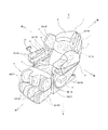
図1〜図4に示すとおり、本発明の第1実施形態に係るマッサージ機1は、主として、使用者が着座する座部2と、座部2の後部にリクライニング可能に設けられた使用者が凭れる背凭れ部3と、座部2の前部に上下揺動可能に設けられた使用者の下肢を支持するフットレスト4と、背凭れ部3の上部前面に設けられた使用者の頭及び/又は首を支持する枕部5と、座部2の左右両側には肘掛け部6と、背凭れ部3の左右両側には側壁部7と、を有している。座部2、背凭れ部3、フットレスト4、枕部5、肘掛け部6、及び側壁部7は、使用者の身体を支持する身体支持部として機能する。身体支持部2〜7の各所には、使用者の身体に対してマッサージを行う後述するエアセル20や後述するバイブレータ21によるマッサージ部15が設けられている。また、マッサージ機1は、背凭れ部3に揉みマッサージ及び/又は叩きマッサージを行うマッサージ部15としてのマッサージユニット8と、マッサージ機1の各動作を制御する制御部9と、使用者に各種操作を行わせるコントローラ10と、有している。
[Overall configuration of massage machine]
As shown in FIGS. 1 to 4, the massage machine 1 according to the first embodiment of the present invention is mainly composed of a seat part 2 on which a user is seated and a user provided on the rear part of the seat part 2 so as to be reclining. The backrest 3 that can be drowned, the footrest 4 that supports the user's lower limb provided on the front part of the seat 2 so as to be able to swing up and down, the user's head provided on the upper front surface of the backrest 3 and The pillow 5 that supports the neck, the armrest 6 on the left and right sides of the seat 2, and the side wall 7 on the left and right sides of the backrest 3 are provided. The seat part 2, the backrest part 3, the footrest 4, the pillow part 5, the armrest part 6, and the side wall part 7 function as a body support part that supports the user's body. In each of the body support portions 2 to 7, there are provided massage portions 15 by air cells 20 (described later) for performing massage on the user's body and vibrators 21 (described later). In addition, the massage machine 1 includes a massage unit 8 as a massage unit 15 that massages and / or strikes the backrest 3, a control unit 9 that controls each operation of the massage machine 1, and various operations for the user. And a controller 10 for performing the above.

図1,図3及び図4に示すとおり、背凭れ部3は、座部2の下方に設けられた第1アクチュエータ11(図3参照)により、座部2に対して前後にリクライニング可能に構成されており、図1に示す起立姿勢から背凭れ面が略水平となるリクライニング姿勢(図4参照)まで変更可能となっている。なお、肘掛け部6は背凭れ部3のリクライニングに連動して後方へ移動し、背凭れ部3の起立に連動して前方へ移動するよう構成されている。フットレスト4は、座部2の下方に設けられた第2アクチュエータ12(図3参照)により、座部2に対して上下に揺動可能に構成されており、図1に示す垂下姿勢から膝を伸ばした状態で下腿及び足部が支持される上昇姿勢(図4参照)まで変更可能となっている。   As shown in FIGS. 1, 3, and 4, the backrest portion 3 is configured to recline back and forth with respect to the seat portion 2 by a first actuator 11 (see FIG. 3) provided below the seat portion 2. Therefore, it is possible to change from the standing posture shown in FIG. 1 to a reclining posture (see FIG. 4) in which the backrest surface is substantially horizontal. The armrest portion 6 is configured to move backward in conjunction with the reclining of the backrest portion 3 and move forward in conjunction with the standing of the backrest portion 3. The footrest 4 is configured to be able to swing up and down with respect to the seat 2 by a second actuator 12 (see FIG. 3) provided below the seat 2, and the knee rests from the suspended posture shown in FIG. It can be changed to a raised posture (see FIG. 4) in which the lower leg and the foot are supported in the stretched state.

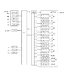
図2,図3に示すとおり、座部2の下方には、エアセル20よりなる各マッサージ部a1〜a8に対してエアを給排気するポンプ13a及びバルブ13bを有する給排気装置13と、前述した制御部9と、が設けられている。各マッサージ部a1〜a8と同じ場所にモータにより駆動されるバイブレータ21を設けてもよい。エアセル20は、エアを給排気することで使用者を押圧することができる。バイブレータ21は、偏心分銅が回転することで使用者に振動を与えることができる。制御部9は、プログラマブルなマイコン等を有しており、各アクチュエータ11,12、マッサージ部15、及び給排気装置13を駆動制御する。制御部9には、前述したコントローラ10が電気的に接続されている。マッサージ機1は、予め定められたプログラム(マッサージコース)に従って動作する他、使用者によるコントローラ10からの指示に従って動作する。   As shown in FIGS. 2 and 3, below the seat portion 2, the air supply / exhaust device 13 having a pump 13 a and a valve 13 b for supplying and exhausting air to the massage portions a <b> 1 to a <b> 8 made of the air cell 20, as described above. And a control unit 9. You may provide the vibrator 21 driven with a motor in the same place as each massage part a1-a8. The air cell 20 can press the user by supplying and exhausting air. The vibrator 21 can give vibration to the user by rotating the eccentric weight. The control unit 9 includes a programmable microcomputer and the like, and drives and controls the actuators 11 and 12, the massage unit 15, and the air supply / exhaust device 13. The controller 10 is electrically connected to the controller 9. The massage machine 1 operates according to instructions from the controller 10 by the user in addition to operating according to a predetermined program (massage course).

コントローラ10を操作することにより、リクライニングさせて背凭れ部3の姿勢を変更することができ、上下に揺動させてフットレスト4の姿勢を変更することができる。また、動作させるマッサージユニット8,各マッサージ部a1〜a8を選択したり、マッサージユニット8,各マッサージ部a1〜a8の動作(手技又は強さ等)を変更したりすることもできる。   By operating the controller 10, the posture of the backrest 3 can be changed by reclining, and the posture of the footrest 4 can be changed by swinging up and down. Moreover, the massage unit 8 to be operated and the massage parts a1 to a8 can be selected, and the operation (technique or strength, etc.) of the massage unit 8 and the massage parts a1 to a8 can be changed.

[座部の構成]
図1〜3に示すとおり、座部2の左右両側には、使用者の臀部及び/又は大腿部の外側面に対向して設けられた壁部22が設けられている。この壁部22は、座部の側方において上方へ立設されている。そして、壁部22の内側面には、臀部及び/又は大腿部の外側面をマッサージする臀部マッサージ部a4が設けられている。座部2の左右両側の肘掛け部6の内側壁を壁部22として利用してもよく、臀部マッサージ部a4を肘掛け部の内側壁に設ければよい。また、座部2には、使用者の臀部及び/又は大腿部を下方(背面)からマッサージする臀部マッサージ部a5が設けられていてもよい。臀部マッサージ部a4,a5は、エアの給排気により膨張収縮するエアセル20により構成されている。このように、臀部マッサージ部a4は左右で対をなしてマッサージ部群A4を構成し、臀部マッサージ部a5は左右で対をなしてマッサージ部群A5を構成している。
[Structure of the seat]
As shown in FIGS. 1-3, the wall part 22 provided facing the outer side surface of a user's buttocks and / or thigh is provided in the right-and-left both sides of the seat part 2. As shown in FIG. The wall portion 22 is erected upward on the side of the seat portion. And the buttock massage part a4 which massages the outer surface of a buttocks and / or a thigh is provided in the inner surface of the wall part 22. As shown in FIG. The inner side walls of the armrest portions 6 on both the left and right sides of the seat portion 2 may be used as the wall portions 22, and the buttocks massage portion a4 may be provided on the inner side walls of the armrest portions. Moreover, the seat part 2 may be provided with a buttocks massage part a5 that massages the user's buttocks and / or thighs from below (back face). The buttocks massage parts a4 and a5 are configured by an air cell 20 that expands and contracts by air supply and exhaust. Thus, the buttocks massage part a4 makes a pair on the left and right to constitute the massage part group A4, and the buttocks massage part a5 makes a pair on the left and right to constitute the massage part group A5.

[背凭れ部の構成]
図1〜図3に示すとおり、背凭れ部3は、硬質の背フレーム3aと、背フレーム3aに組み付けられたマッサージ部15であるマッサージユニット8の昇降をガイドするガイドレール18と、背フレーム3aを被覆するカバー部材3cと、により構成されている。背フレーム3aは、金属部材及び/又は樹脂部材により構成されている。また、背フレーム3aは、左右中央に形成された前後方向に開口する開口部3bを有し、正面視で略門型をなしている。また、カバー部材3cは、開口部3bを前方から覆っている。マッサージユニット8の施療子62(図5参照)が開口部3bより前方へ突出しており、カバー部材3cを介して使用者の胴体を後方からマッサージできるようになっている。
[Configuration of backrest]
As shown in FIGS. 1 to 3, the backrest 3 includes a rigid back frame 3a, a guide rail 18 that guides the lifting and lowering of the massage unit 8 that is a massage unit 15 assembled to the back frame 3a, and the back frame 3a. And a cover member 3c covering the surface. The back frame 3a is configured by a metal member and / or a resin member. Moreover, the back frame 3a has an opening 3b that is formed at the center in the left-right direction and opens in the front-rear direction, and has a substantially gate shape when viewed from the front. The cover member 3c covers the opening 3b from the front. A treatment element 62 (see FIG. 5) of the massage unit 8 protrudes forward from the opening 3b so that the body of the user can be massaged from the rear via the cover member 3c.

[マッサージユニットの構成]
以下、マッサージユニット8の構成について説明する。
図1〜図3,図5に示すとおり、背凭れ部3には、使用者の上半身を後方(背面)からマッサージするマッサージユニット8が設けられている。このマッサージユニット8は、身長方向に沿って複数(本実施形態では1つ)設けられていてもよい。このマッサージユニット8は、左右で対をなすアーム61と、アーム61の上下両端部に設けられた施療子62と、により構成されており、マッサージモータM1,M2の駆動により左右の施療子62が近接離反する揉みマッサージ、及び左右の施療子62が交互に使用者側へ進退する叩きマッサージを行わせることができる。また、マッサージユニット8は、昇降モータM3の駆動により身長方向に沿って上方又は下方へ移動して、身体に対する位置を変更したり、ローリングマッサージを行わせたりすることができる。背フレーム3aには、身長方向に延設された左右で対をなすガイドレール18が設けられており、マッサージユニット8はガイドレール18に沿って移動する。マッサージユニット8が身長方向に移動可能であるため、使用者の首から腰の間を施療子62でマッサージすることができる。
[Composition of massage unit]
Hereinafter, the configuration of the massage unit 8 will be described.
As shown in FIGS. 1 to 3 and 5, the backrest part 3 is provided with a massage unit 8 for massaging the user's upper body from the back (back). A plurality (one in this embodiment) of the massage unit 8 may be provided along the height direction. The massage unit 8 includes an arm 61 that is paired on the left and right sides, and treatment elements 62 that are provided at both upper and lower ends of the arm 61. The left and right treatment elements 62 are driven by the massage motors M1 and M2. It is possible to perform a massage massage that moves close to and away from each other and a tapping massage in which the left and right treatment elements 62 advance and retreat alternately. Moreover, the massage unit 8 can move upward or downward along the height direction by driving the elevating motor M3 to change the position relative to the body or perform a rolling massage. The back frame 3 a is provided with a pair of left and right guide rails 18 extending in the height direction, and the massage unit 8 moves along the guide rail 18. Since the massage unit 8 is movable in the height direction, a massage element 62 can massage between the user's neck and waist.

図5に示すとおり、マッサージユニット8は、ベースフレーム60aと、ベースフレーム60aに支持された可動フレーム60bと、を有している。ベースフレーム60aは、その左右両側においてガイドレール18に嵌合するガイドローラ63を有している。そして、ラックピニオン等よりなる昇降機構(図示せず)によって、身長方向に沿って移動することができる。可動フレーム60bは、左右方向の揺動軸64を介してベースフレーム60aに支持されている。ベースフレーム60aと可動フレーム60bの間には、エアセル等よりなる進退駆動部65が設けられている。進退駆動部65の駆動により、可動フレーム60bは揺動軸64を中心として前後方向に進退することができる。なお、可動フレーム60bを進退させる構造でなくてもよく、アーム61に進退駆動部65を設けてアーム61のみを進退させる構造であってもよい。   As shown in FIG. 5, the massage unit 8 includes a base frame 60a and a movable frame 60b supported by the base frame 60a. The base frame 60a has guide rollers 63 fitted to the guide rails 18 on both the left and right sides. And it can move along a height direction by the raising / lowering mechanism (not shown) which consists of rack pinions etc. The movable frame 60b is supported by the base frame 60a via a swing shaft 64 in the left-right direction. Between the base frame 60a and the movable frame 60b, an advancing / retreating drive unit 65 made of an air cell or the like is provided. By driving the advance / retreat drive unit 65, the movable frame 60 b can advance and retract in the front-rear direction about the swing shaft 64. Note that the movable frame 60b may not be configured to advance or retract, and the arm 61 may be provided with the advance / retreat drive unit 65 to advance or retract only the arm 61.

アーム61は、左右方向に延設された揉み軸66及び叩き軸67に連結されている。揉み軸66の左右両側には、傾斜軸部66bを有する傾斜カム66aが設けられており、この傾斜カム66aにアーム61が取り付けられている。左右の傾斜軸部66bは、正面視で略ハの字型となるように揉み軸66の軸心に対して傾斜している。叩き軸67の左右両側には、叩き軸67の軸心に対して偏心した偏心軸部67bを有する偏心カム67aが設けられており、この偏心カム67aにアーム61がコンロッド68を介して取り付けられている。左右の偏心軸部67bは、叩き軸67の軸心に対する位相が互いに異なっており、具体的には180度だけ異なっている。揉み軸66及び叩き軸67は、それぞれマッサージモータM1,M2の駆動により回転する。施療子62は、揉み軸66の回転により揉みマッサージを行い、叩き軸67の回転により叩きマッサージを行う。なお、施療子62が設けられたアーム61、揉み軸66、及び叩き軸67は、可動フレーム60bに支持されている。従って、施療子62は、可動フレーム60bの移動を介して使用者に対して進退可能である。   The arm 61 is connected to a rubbing shaft 66 and a hitting shaft 67 extending in the left-right direction. An inclined cam 66a having an inclined shaft portion 66b is provided on both the left and right sides of the rubbing shaft 66, and an arm 61 is attached to the inclined cam 66a. The left and right inclined shaft portions 66b are inclined with respect to the axis of the rubbing shaft 66 so as to be substantially C-shaped when viewed from the front. An eccentric cam 67 a having an eccentric shaft portion 67 b that is eccentric with respect to the axis of the hitting shaft 67 is provided on both the left and right sides of the hitting shaft 67, and the arm 61 is attached to the eccentric cam 67 a via a connecting rod 68. ing. The left and right eccentric shaft portions 67b are different from each other in phase with respect to the axis of the hitting shaft 67, specifically, 180 degrees. The kneading shaft 66 and the hitting shaft 67 are rotated by driving the massage motors M1 and M2, respectively. The treatment element 62 performs massaging massage by the rotation of the massaging shaft 66, and performs massaging massage by the rotation of the hammering shaft 67. The arm 61 provided with the treatment element 62, the kneading shaft 66, and the hitting shaft 67 are supported by the movable frame 60b. Therefore, the treatment element 62 can advance and retreat with respect to the user through the movement of the movable frame 60b.

アーム61は、前後方向に揺動自在であり、上側の施療子62が前方へ突出するようにバネ等よりなる付勢手段(図示せず)により付勢されている。また、マッサージユニット8は、使用者の身体情報を検出するセンサ69(図3参照)を有している。このセンサ69は、アーム61が所定の揺動位置となったことを検出することで身体情報を得ることができる。具体的に説明すると、マッサージユニット8を身長方向に沿って上昇させる過程で、上側の施療子62が肩の上方に到達すると、施療子62に作用する負荷が解除されて、アーム61が前方へ揺動して所定の揺動位置となる。アーム61が所定の揺動位置となったことをセンサ69が検出し、その際のマッサージユニット8の上下位置に基づいて肩の位置を検出する。肩の位置を基準として、その他の部位(首、背中、腰等)の位置を計算により求める。検出された身体情報は制御部9に記憶される。   The arm 61 is swingable in the front-rear direction, and is biased by biasing means (not shown) made of a spring or the like so that the upper treatment element 62 protrudes forward. Moreover, the massage unit 8 has a sensor 69 (see FIG. 3) that detects the user's physical information. The sensor 69 can obtain physical information by detecting that the arm 61 has reached a predetermined swinging position. More specifically, when the upper treatment element 62 reaches above the shoulder in the process of raising the massage unit 8 along the height direction, the load acting on the treatment element 62 is released, and the arm 61 moves forward. It swings to a predetermined swing position. The sensor 69 detects that the arm 61 has reached a predetermined swing position, and detects the position of the shoulder based on the vertical position of the massage unit 8 at that time. The position of other parts (neck, back, waist, etc.) is obtained by calculation based on the position of the shoulder. The detected physical information is stored in the control unit 9.

[側壁部の構成]
図1〜図2に示すとおり、背フレーム3a(背凭れ部3)の左右両側には、使用者の肩又は上腕の外側面に対向して設けられた側壁部7が設けられている。この側壁部7は、背凭れ部3の側方において前方へ立設されている。そして、側壁部7の内側面には、肩又は上腕の外側面をマッサージする肩側マッサージ部a2が設けられている。肩側マッサージ部a2は、エアの給排気により膨張収縮するエアセル20により構成されている。このように、肩側マッサージ部a2は左右で対をなしてマッサージ部群A2を構成している。
[Configuration of side wall]
As shown in FIGS. 1 to 2, side wall portions 7 are provided on both the left and right sides of the back frame 3 a (backrest portion 3) so as to face the outer surface of the user's shoulder or upper arm. The side wall portion 7 is erected forward on the side of the backrest portion 3. And the shoulder side massage part a2 which massages the outer surface of a shoulder or an upper arm is provided in the inner surface of the side wall part 7. As shown in FIG. The shoulder side massage part a2 is configured by an air cell 20 that expands and contracts by air supply and exhaust. Thus, the shoulder side massage part a2 forms a massage part group A2 in pairs on the left and right.

[枕部の構成]
図1〜図3に示すとおり、背凭れ部3の上部前面には、使用者の頭及び/又は首を支持する枕部5が設けられている。枕部5の前面には、頭及び/又は首の後面に対向して設けられた左右で対をなす頭部マッサージ部a1が設けられている。頭部マッサージ部a1は、エアの給排気により膨張収縮するエアセル20により構成されている。このように、頭部マッサージ部a1は、左右で対をなしてマッサージ部群A1を構成している。この頭部マッサージ部a1は、頭及び/又は首の外側面に対向して設けてもよい。この場合は、前方へ立設された壁部(図示せず)の内側面に設けるとよい。また、頭部マッサージ部a1は、枕部5に設けるのではなく、背凭れ部3の上部前面に直接設けてもよい。
[Composition of pillow part]
As shown in FIGS. 1 to 3, a pillow portion 5 that supports the user's head and / or neck is provided on the upper front surface of the backrest portion 3. On the front surface of the pillow portion 5, there is provided a head massage portion a <b> 1 that is paired on the left and right sides that is provided to face the rear surface of the head and / or neck. The head massage part a1 is composed of an air cell 20 that expands and contracts by air supply and exhaust. Thus, the head massage part a1 comprises the massage part group A1 by making a pair on the left and right. This head massage part a1 may be provided facing the outer surface of the head and / or neck. In this case, it is good to provide in the inner surface of the wall part (not shown) erected ahead. Further, the head massage part a <b> 1 may be provided directly on the upper front surface of the backrest part 3 instead of being provided in the pillow part 5.

[肘掛け部の構成]
図1〜図3に示すとおり、座部2の左右両側には、使用者の手先と前腕を支持する肘掛け部6が設けられている。肘掛け部6の手先と前腕の上下方向には、腕マッサージ部a3が設けられている。腕マッサージ部a3は、エアの給排気により膨張収縮するエアセル20により構成されている。このように、腕マッサージ部a3は、左右で対をなしてマッサージ部群A3を構成している。
[Configuration of armrest]
As shown in FIGS. 1 to 3, armrests 6 that support the user's hand and forearm are provided on the left and right sides of the seat 2. An arm massage part a3 is provided in the vertical direction of the hand and forearm of the armrest 6. The arm massage part a3 is composed of an air cell 20 that expands and contracts by air supply and exhaust. Thus, the arm massage part a3 comprises the massage part group A3 by making a pair on the left and right.

[フットレストの構成]
以下フットレスト4の構成について説明する。図6は本発明の第1実施形態に係るマッサージ機1のフットレスト4の足支持部41の平面図である。
[Composition of footrest]
Hereinafter, the configuration of the footrest 4 will be described. FIG. 6 is a plan view of the foot support 41 of the footrest 4 of the massage machine 1 according to the first embodiment of the present invention.

図1〜図3に示すとおり、フットレスト4は、使用者の下腿を支持する左右一対の脚支持部40と、使用者の足部を支持する左右一対の足支持部41と、を有している。脚支持部40は、使用者の下腿の背面に対向して設けられた底壁40aと、底壁40aの左右両端から前方に向かって立設された側壁40bと、底壁40aの左右中央から前方に向かって立設された中央壁40cと、を有している。   As shown in FIG. 1 to FIG. 3, the footrest 4 includes a pair of left and right leg support portions 40 that support the user's lower leg and a pair of left and right foot support portions 41 that support the user's foot. Yes. The leg support portion 40 includes a bottom wall 40a provided facing the back of the user's lower leg, a side wall 40b erected forward from the left and right ends of the bottom wall 40a, and a left and right center of the bottom wall 40a. And a central wall 40c erected forward.

側壁40bの内側面には、下腿の外側面をマッサージする脚マッサージ部a6が設けられている。中央壁40cの両外側面には、下腿の内側面をマッサージする脚マッサージ部a6が設けられている。また、底壁40aには、使用者の下腿の背面からマッサージする脚マッサージ部a7が設けられている。脚マッサージ部a6,a7は、エアの給排気により膨張収縮するエアセル20により構成されている。脚マッサージ部a6は、下腿の内側面に対向する脚マッサージ部a6と、下腿の外側面に対向する脚マッサージ部a6、により左右で対をなしてマッサージ部群A6を構成している。脚マッサージ部a7は、中央壁40cを挟んで左側の下腿の背面に対向する脚マッサージ部a7と、中央壁40cを挟んで右側の下腿の背面に対向する脚マッサージ部a7と、により左右で対をなしてマッサージ部群A7を構成している。   A leg massage part a6 for massaging the outer side surface of the lower leg is provided on the inner side surface of the side wall 40b. On both outer sides of the central wall 40c, leg massage parts a6 for massaging the inner side of the lower leg are provided. The bottom wall 40a is provided with a leg massage part a7 for massaging from the back of the user's lower leg. The leg massage parts a6 and a7 are configured by an air cell 20 that expands and contracts by air supply and exhaust. The leg massage part a6 forms a massage part group A6 by making a pair on the left and right by a leg massage part a6 facing the inner side of the lower leg and a leg massage part a6 facing the outer side of the lower leg. The leg massage part a7 is paired with the leg massage part a7 facing the back of the left lower leg across the central wall 40c and the leg massage part a7 facing the back of the right lower leg across the central wall 40c. The massage part group A7 is comprised.

図1〜図3及び図6に示すとおり、足支持部41は、使用者の足裏を置く底壁41aと、底壁41aの左右両端から上方に向かって立設された側壁41bと、底壁41aの左右中央から上方に向かって立設された中央壁41cと、底壁41aの後部から上方へ立設された足部の背面(踵付近)に対向する後壁41dと、を有している。各壁41a〜41dより上方及び前方が開口した凹部42が形成されており、凹部42に足部を収容できるようになっている。   As shown in FIG. 1 to FIG. 3 and FIG. 6, the foot support portion 41 includes a bottom wall 41 a on which a user's sole is placed, a side wall 41 b erected upward from the left and right ends of the bottom wall 41 a, A central wall 41c erected upward from the left and right center of the wall 41a, and a rear wall 41d facing the rear surface (near the heel) of the foot erected upward from the rear part of the bottom wall 41a. ing. A recess 42 is formed with openings above and in front of the walls 41 a to 41 d so that the foot can be accommodated in the recess 42.

各壁41a〜41cには、使用者の足をマッサージする足マッサージ部a8が設けられ、左右で対をなしてマッサージ群A8を構成している。足マッサージ部a8は、前側を膨張支点としてエアの給排気により膨張収縮するエアセル20で構成され、使用者の踵を押圧施療する後述する足第1マッサージ部81,82と、使用者の足の爪先を下方から持ち上げるように押圧施療する後述する足第2マッサージ部83と、使用者の足の爪先を側方と上方の何れか一方又は両方から押圧施療する後述する足第3マッサージ部84と、を有している。   Each wall 41a-41c is provided with a foot massage part a8 for massaging the user's foot, and constitutes a massage group A8 in pairs on the left and right. The foot massage part a8 is composed of an air cell 20 that expands and contracts by air supply / exhaust with the front side as an expansion fulcrum, and a foot first massage part 81, 82 described later that presses and treats the user's heel, A foot second massage part 83 to be described later that presses and treats the toes from below, and a foot third massage part 84 to be described later that presses and treats the user's toes from either the side or the upper side or both. ,have.

足第1マッサージ部81は、側壁41bの後側(踵付近)と中央壁41cの後側(踵付近)とに設けられ、前側を膨張支点として膨張収縮するエアセル20で使用者の踵の側部を挟んで押圧施療することができる。使用者の踵の側部の形状は、前側から後側にいくに連れて左右幅が狭くなっている。この様に構成することで、膨張支点が前側にあるためエアセル20の後側が1番膨張することになる。それにより踵の側部の形状に合わせてエアセル20を膨張させることができ、踵の側部の後側までしっかりと挟むことができる。また、側壁41bの後側(踵付近)と中央壁41cの後側(踵付近)とに設けられたエアセル20は、いずれか一方に設けられてもよいし、両方に設けられてもよい。例えば、側壁41bだけにエアセル20を設けた場合、エアセル20と中央壁41cとで踵の側部を挟むことができる。   The first foot massage part 81 is provided on the rear side (near the heel) of the side wall 41b and the rear side (near the heel) of the central wall 41c, and is on the side of the user's heel with the air cell 20 that expands and contracts with the front side as an expansion fulcrum. Press treatment can be performed with the part interposed therebetween. As for the shape of the side part of the user's heel, the lateral width is narrowed from the front side to the rear side. By configuring in this way, since the expansion fulcrum is on the front side, the rear side of the air cell 20 is expanded most. Thereby, the air cell 20 can be expanded in accordance with the shape of the side portion of the heel, and can be firmly sandwiched to the rear side of the side portion of the heel. The air cells 20 provided on the rear side (near the ridge) of the side wall 41b and the rear side (near the ridge) of the central wall 41c may be provided on either one or both. For example, when the air cell 20 is provided only on the side wall 41b, the side portion of the bag can be sandwiched between the air cell 20 and the central wall 41c.

足第1マッサージ部82は、底壁41aの後側に設けられ、前側を膨張支点として膨張収縮するエアセル20で使用者の踵の後部を下方から持ち上げるように押圧施療することができる。この様に構成することで、膨張支点が前側にあるためエアセル20の後側が1番膨張することになる。それにより踵の後部を下方から1番膨張させることができ、踵の後部を下方からより持ち上げることができる。   The first foot massage part 82 is provided on the rear side of the bottom wall 41a, and can be pressed to lift the rear part of the user's heel from below with the air cell 20 that expands and contracts with the front side as an expansion fulcrum. By configuring in this way, since the expansion fulcrum is on the front side, the rear side of the air cell 20 is expanded most. Thereby, the rear part of the heel can be expanded from the lowermost position, and the rear part of the heel can be lifted from the lower side.

足第2マッサージ部83は、底壁41aの前側に設けられ、エアの給排気により膨張収縮するエアセル20で構成されている。この様に構成することで、使用者の足の爪先を下方から持ち上げるように押圧施療することができる。また、底壁41aの前側に設けられるエアセル20の膨張支点を後側にしてもよい。そうすることでエアセル20の前側が1番膨張し、足の爪先を下方からより持ち上がることができる。   The 2nd leg massage part 83 is provided in the front side of the bottom wall 41a, and is comprised by the air cell 20 which expands / contracts by supply / exhaust of air. By comprising in this way, it can press-treat so that a toe of a user's foot may be lifted from the downward direction. Further, the expansion fulcrum of the air cell 20 provided on the front side of the bottom wall 41a may be on the rear side. By doing so, the front side of the air cell 20 is inflated most, and the toe of the foot can be lifted from below.

足第3マッサージ部84は、側壁41bの前側と中央壁41cの前側に設けられ、エアの給排気により膨張収縮するエアセル20で構成されている。この様に構成することで、使用者の足の爪先を側方と上方から押圧施療することができる。側壁41bの前側と中央壁41cの前側に設けられたエアセル20は、膨張支点を下方とすることで足の爪先を上方から押圧施療することができ、膨張支点がなくても足の爪先を側方から押圧施療することができる。また、側壁41bの前側と中央壁41cの前側に設けられたエアセル20は、いずれか一方に設けられてもよいし、両方に設けられてもよい。例えば、側壁41bだけにエアセル20を設けた場合でも、使用者の足の爪先を側方と上方から押圧施療することができる。   The third leg massage part 84 is provided on the front side of the side wall 41b and the front side of the central wall 41c, and is composed of the air cell 20 that expands and contracts by air supply and exhaust. By comprising in this way, a toe of a user's foot | toe can be pressed and treated from the side and the upper part. The air cell 20 provided on the front side of the side wall 41b and the front side of the central wall 41c can press and treat the toe of the foot from above by setting the expansion fulcrum downward, and even if there is no expansion fulcrum, the air toe Can be pressed from the side. Moreover, the air cell 20 provided in the front side of the side wall 41b and the front side of the center wall 41c may be provided in any one, and may be provided in both. For example, even when the air cell 20 is provided only on the side wall 41b, the user's toes can be pressed and treated from the side and from above.

以下、マッサージ機1の制御について説明する。
図7は、側面から見た足支持部41の足マッサージ部a8の動作を示す図である。
図7(a),図7(b),図7(c)は、足支持部41に使用者の足を載せた状態での足マッサージ部a8との位置関係を示しており、図7(a)は足支持部41に使用者の足を載せた状態の図であり、図7(b)は、足首ストレッチである足関節の背屈動作(足首を足の甲側に動かす)を行う第1ステップの図である。図7(c)は、足首ストレッチである足関節の背屈動作(足首を足の甲側に動かす)を行う第2ステップの図である。
図8(a),図8(b),図8(c)は、足支持部41に使用者の足を載せた状態での足マッサージ部a8との位置関係を示しており、図8(a)は足支持部41に使用者の足を載せた状態の図であり、図8(b)は、足首ストレッチである足関節の底屈動作(足首を足の裏側に動かす)を行う第1ステップの図である。図8(c)は、足首ストレッチである足関節の底屈動作(足首を足の裏側に動かす)を行う第2ステップの図である。
Hereinafter, control of the massage machine 1 will be described.
FIG. 7 is a diagram illustrating the operation of the foot massage part a8 of the foot support part 41 as viewed from the side.
FIG. 7A, FIG. 7B, and FIG. 7C show the positional relationship with the foot massage part a8 in a state where the user's foot is placed on the foot support part 41. FIG. FIG. 7A is a diagram showing a state where a user's foot is placed on the foot support portion 41, and FIG. 7B is a diagram illustrating an ankle stretch dorsiflexion operation (moving the ankle toward the back of the foot). It is a figure of a 1st step. FIG.7 (c) is a figure of the 2nd step which performs the dorsiflexion operation | movement of the ankle joint which moves an ankle (it moves an ankle to the instep side of an ankle).
FIG. 8A, FIG. 8B, and FIG. 8C show the positional relationship with the foot massage part a8 in a state where the user's foot is placed on the foot support part 41. FIG. FIG. 8A is a diagram showing a state where a user's foot is placed on the foot support portion 41, and FIG. 8B is a diagram illustrating a case where the ankle joint is bent to the bottom (the ankle is moved to the back side of the foot). It is a figure of 1 step. FIG.8 (c) is a figure of the 2nd step which performs the plantar bending operation | movement (moving an ankle to the back side of a foot) which is an ankle stretch.

[動作1について]
以下、使用者の足に対して足首ストレッチである足関節の背屈動作の一例について、図7(a),図7(b),図7(c)に基づいて説明する。
制御部9は、足第1マッサージ部81と足第2マッサージ部83を駆動させることで、足の踵の側部を挟持した状態で足の爪先を下方から持ち上げて足首ストレッチである足関節の背屈動作を行うことができる。まず、制御部9は、足支持部41に足を載せた状態(図7(a)参照)から第1ステップ(図7(b)参照)において、足第1マッサージ部81を駆動させて足の踵の側部を挟持し、足の踵を固定させる。第2ステップ(図7(c)参照)において、第1ステップにより足の踵の側部を挟持した状態で足第2マッサージ部83を駆動させて、足の爪先を下方から持ち上げる。このように制御することで、使用者の足全体が浮き上がることなく、足の爪先の前側だけを下方から持ち上げることができ、足に対して背屈動作をさせ、足首ストレッチを行うことができる。なお、第1ステップと第2ステップの動作を同時に行うように足第1マッサージ部81と足第2マッサージ部83を制御してもよい。
[About operation 1]
Hereinafter, an example of the dorsiflexion operation of the ankle joint, which is an ankle stretch with respect to the user's foot, will be described with reference to FIGS. 7 (a), 7 (b), and 7 (c).
The control unit 9 drives the foot first massage unit 81 and the foot second massage unit 83 to lift the toe of the foot from below while sandwiching the side of the heel of the foot, so that the ankle joint is an ankle stretch. A dorsiflexion movement can be performed. First, the control unit 9 drives the foot first massage unit 81 in the first step (see FIG. 7B) from the state where the foot is placed on the foot support unit 41 (see FIG. 7A), and the foot. Hold the side of the heel and fix the heel of the foot. In the second step (see FIG. 7C), the foot second massage part 83 is driven in a state in which the side part of the foot heel is sandwiched by the first step, and the toe of the foot is lifted from below. By controlling in this way, only the front side of the toe of the foot can be lifted from below without lifting the entire foot of the user, and the ankle can be stretched by performing a dorsiflexion operation on the foot. In addition, you may control the 1st massage part 81 and the 2nd massage part 83 so that the operation | movement of a 1st step and a 2nd step may be performed simultaneously.

[動作2について]
以下、使用者の足に対して足首ストレッチである足関節の底屈動作の一例について、図8(a),図8(b),図8(c)に基づいて説明する。
制御部9は、足第1マッサージ部82と足第3マッサージ部84を駆動させることで、足の爪先を側方と上方から押圧した状態で足の踵の後部を下方から持ち上げて足首ストレッチである足関節の底屈動作を行うことができる。まず、制御部9は、足支持部41に足を載せた状態(図8(a)参照)から第1ステップ(図8(b)参照)において、足第3マッサージ部84を駆動させて足の爪先を側方と上方から押圧し、足の爪先を固定させる。第2ステップ(図8(c)参照)において、第1ステップにより足の爪先を側方と上方から押圧した状態で足第1マッサージ部82を駆動させて、足の踵の後部を下方から持ち上げる。このように制御することで、使用者の足全体が浮き上がることなく、足の踵の後部だけを下方から持ち上げることができ、足に対して底屈動作をさせ、足首ストレッチを行うことができる。なお、第1ステップと第2ステップの動作を同時に行うように足第1マッサージ部82と足第3マッサージ部84を制御してもよい。
[About operation 2]
Hereinafter, an example of an ankle plantar flexion operation which is an ankle stretch with respect to the user's foot will be described with reference to FIGS. 8A, 8B, and 8C.
The control unit 9 drives the foot first massage unit 82 and the foot third massage unit 84 to lift the rear part of the heel of the foot from below while pressing the toes of the foot from the side and from above. A plantar flexion motion of a certain ankle joint can be performed. First, the controller 9 drives the foot third massager 84 from the state where the foot is placed on the foot support 41 (see FIG. 8A) to the first step (see FIG. 8B) to drive the foot. The toes are pressed from the side and from above to fix the toes. In the second step (see FIG. 8 (c)), the foot first massage part 82 is driven in a state where the toes of the foot are pressed from the side and above in the first step, and the rear part of the foot heel is lifted from below. . By controlling in this way, it is possible to lift only the rear part of the heel of the foot from below without lifting the entire foot of the user, allowing the foot to bend and perform ankle stretching. Note that the first foot massage part 82 and the third foot massage part 84 may be controlled so that the operations of the first step and the second step are performed simultaneously.

[他の実施形態]
また、本発明のマッサージ機1は、図示する形態に限らず、この発明の範囲内において他の形態のものであってもよい。例えば、前述した実施形態では足支持部41で説明したが、肘掛け部6の手支持部60の構成であった場合、以下の様になる。
図9は、使用者の前腕から手先が図示されており、肘掛け部6の手支持部60が簡略化して図示されている。
図9に示すとおり、肘掛け部6は、使用者の手先を支持する手支持部60を有している。手支持部60は、手の平が前側に向くようにした状態の手の平と対向する前壁60aと、前壁60aの左右両端から後方に立設した側壁60b(図示せず)と、前壁60aの下端から後方に立設した使用者の前腕を置く下壁60cと、を有している。前壁60aには、手の爪先を後方に移動させるエアセル20からなる腕マッサージ部30と、手の平の後部を後方に移動させるエアセル20からなる腕マッサージ部31と、が設けられている。側壁60bには、手の甲を側方と後方から押圧するエアセル20からなる腕マッサージ部32と、手首を側方と上方から押圧するエアセル20からなる腕マッサージ部33と、が設けられている。
[Other Embodiments]
Moreover, the massage machine 1 of this invention is not restricted to the form to show in figure, The thing of another form may be sufficient within the scope of this invention. For example, in the above-described embodiment, the foot support portion 41 has been described. However, in the case of the configuration of the hand support portion 60 of the armrest portion 6, the following is obtained.
FIG. 9 shows the hand from the user's forearm, and the hand support 60 of the armrest 6 is shown in a simplified manner.
As shown in FIG. 9, the armrest portion 6 has a hand support portion 60 that supports the user's hand. The hand support 60 includes a front wall 60a facing the palm in a state where the palm faces the front side, a side wall 60b (not shown) standing rearward from the left and right ends of the front wall 60a, and the front wall 60a. And a lower wall 60c for placing the user's forearm standing rearward from the lower end. The front wall 60a is provided with an arm massage part 30 composed of an air cell 20 that moves the toe of the hand backward, and an arm massage part 31 composed of the air cell 20 that moves the rear part of the palm backward. The side wall 60b is provided with an arm massage part 32 composed of an air cell 20 that presses the back of the hand from the side and the rear, and an arm massage part 33 composed of the air cell 20 that presses the wrist from the side and from above.

制御部9は、腕マッサージ部30〜33の駆動を制御することで、手首に対して底屈運動及び背屈運動の手首ストレッチを行うことができる。   The control unit 9 can perform wrist flexion exercise and wrist flexion exercise for the wrist by controlling the driving of the arm massage units 30 to 33.

本発明は、使用者の踵の側部の形状に合わせて、踵の側部をしっかりと挟むことができ、又は踵の後部を下方からより持ち上げることができるマッサージ機に適用することができる。   INDUSTRIAL APPLICABILITY The present invention can be applied to a massage machine that can firmly sandwich the side of the heel in accordance with the shape of the side of the user's heel, or can lift the back of the heel from below.

1 マッサージ機
9 制御部
15 マッサージ部
20 エアセル(マッサージ部)
41 足支持部
41a 底壁
41b 側壁
41c 中央壁
81a 足第1マッサージ部(足マッサージ部)
82a 足第1マッサージ部(足マッサージ部)
83a 足第2マッサージ部(足マッサージ部)
84a 足第3マッサージ部(足マッサージ部)
a8 足マッサージ部(マッサージ部)
1 Massage machine 9 Control part 15 Massage part 20 Air cell (massage part)
41 foot support part 41a bottom wall 41b side wall 41c central wall 81a first foot massage part (foot massage part)
82a Foot first massage part (foot massage part)
83a Foot second massage part (foot massage part)
84a Foot third massage part (foot massage part)
a8 foot massage part (massage part)

Claims (7)

使用者の足部を支持する左右一対の足支持部を備えるマッサージ機において、
前記足支持部は、
使用者の足裏を置く底壁と、
前記底壁の左右両端から上方に向かって立設された側壁と、
前記底壁の左右中央から上方に向かって立設された中央壁と、
前記底壁と前記側壁と前記中央壁との少なくとも1つに設けられ、使用者の足をマッサージする足マッサージ部と、を有し、
前記足マッサージ部を制御する制御部を有し、
前記足マッサージ部は、前側を膨張支点として膨張収縮するエアセルで構成され、使用者の踵を押圧施療する足第1マッサージ部を有することを特徴とするマッサージ機。
In a massage machine comprising a pair of left and right foot support parts that support the user's foot parts,
The foot support is
A bottom wall on which the user's feet are placed;
Side walls erected upward from the left and right ends of the bottom wall;
A central wall erected upward from the left and right center of the bottom wall;
A foot massager that is provided on at least one of the bottom wall, the side wall, and the central wall and massages a user's foot;
A control unit for controlling the foot massage unit;
The foot massage part is composed of an air cell that expands and contracts with the front side as an expansion fulcrum, and has a first leg massage part that presses and treats a user's heel.
前記足第1マッサージ部は、前記側壁と前記中央壁の少なくとも1つに設けられ、使用者の踵の側部を挟んで押圧施療することを特徴とする請求項1に記載のマッサージ機。   2. The massage machine according to claim 1, wherein the first foot massage part is provided on at least one of the side wall and the central wall, and presses and treats a side part of a user's heel. 3. 前記足第1マッサージ部は、前記底壁に設けられ、使用者の踵の後部を下方から持ち上げるように押圧施療することを特徴とする請求項1又は2に記載のマッサージ機。   3. The massage machine according to claim 1, wherein the first foot massage part is provided on the bottom wall and performs pressure treatment so as to lift a rear part of a user's heel from below. 前記足マッサージ部は、前記底壁に設けられ、使用者の足の爪先を下方から持ち上げるように押圧施療する足第2マッサージ部を有することを特徴とする請求項1〜3にいずれかに記載のマッサージ機。   The said foot massage part is provided in the said bottom wall, and has a leg 2nd massage part which presses and treats so that the toe of a user's foot may be lifted from the downward direction, The Claim 1 characterized by the above-mentioned. Massage machine. 前記足マッサージ部は、前記側壁と前記中央壁の少なくとも一方に設けられ、使用者の足の爪先を側方と上方の何れか一方又は両方から押圧施療する足第3マッサージ部を有することを特徴とする請求項1〜4にいずれかに記載のマッサージ機。   The foot massage part has a foot third massage part which is provided on at least one of the side wall and the central wall and presses and treats a toe of a user's foot from either one or both of the side and the upper side. The massage machine according to any one of claims 1 to 4. 前記制御部は、前記足第1マッサージ部で踵の側部を挟持した後、前記足第2マッサージ部で足の爪先を持ち上げて足首ストレッチを行う制御をすることを特徴とする請求項4に記載のマッサージ機。   The said control part performs control which lifts the toe of a foot | leg by the said 2nd massage part, and performs ankle stretch after pinching the side part of a heel with the said 1st foot massage part. The listed massage machine. 前記制御部は、前記足第3マッサージ部で足の爪先を側方と上方の何れか一方又は両方から押圧した後、前記足第1マッサージ部で踵の後部を下方から持ち上げて足首ストレッチを行う制御をすることを特徴とする請求項5に記載のマッサージ機。
The control unit performs ankle stretching by pressing the toe of the foot from either one or both of the side and the upper side, or both by the third foot massage unit, and then lifting the rear part of the heel from the lower side by the first foot massage unit. It controls, The massage machine of Claim 5 characterized by the above-mentioned.
JP2016147594A 2016-07-27 2016-07-27 Massage machine Pending JP2018015214A (en)

Priority Applications (1)

Application Number Priority Date Filing Date Title
JP2016147594A JP2018015214A (en) 2016-07-27 2016-07-27 Massage machine

Applications Claiming Priority (1)

Application Number Priority Date Filing Date Title
JP2016147594A JP2018015214A (en) 2016-07-27 2016-07-27 Massage machine

Publications (1)

Publication Number Publication Date
JP2018015214A true JP2018015214A (en) 2018-02-01

Family

ID=61075444

Family Applications (1)

Application Number Title Priority Date Filing Date
JP2016147594A Pending JP2018015214A (en) 2016-07-27 2016-07-27 Massage machine

Country Status (1)

Country Link
JP (1) JP2018015214A (en)

Cited By (1)

* Cited by examiner, † Cited by third party
Publication number Priority date Publication date Assignee Title
JP2020081680A (en) * 2018-11-30 2020-06-04 株式会社フジ医療器 Treatment machine and chair type massage machine comprising the same

Citations (7)

* Cited by examiner, † Cited by third party
Publication number Priority date Publication date Assignee Title
JPH0889540A (en) * 1994-07-29 1996-04-09 Tec Corp Air massage machine
US20040005972A1 (en) * 2002-07-08 2004-01-08 Toshihide Sugiyama Exercise apparatus
JP2004089672A (en) * 2002-07-08 2004-03-25 Skylite Corporation Athletic equipment
JP2004215938A (en) * 2003-01-16 2004-08-05 Family Co Ltd Chair type massage apparatus
JP2009034231A (en) * 2007-07-31 2009-02-19 Fuji Iryoki:Kk Chair type massage machine
JP3169199U (en) * 2011-05-09 2011-07-21 利士多国際有限公司St Life Co.,Ltd. Hand and leg massager
JP3188361U (en) * 2013-10-30 2014-01-16 株式会社アテックス Massage equipment

Patent Citations (7)

* Cited by examiner, † Cited by third party
Publication number Priority date Publication date Assignee Title
JPH0889540A (en) * 1994-07-29 1996-04-09 Tec Corp Air massage machine
US20040005972A1 (en) * 2002-07-08 2004-01-08 Toshihide Sugiyama Exercise apparatus
JP2004089672A (en) * 2002-07-08 2004-03-25 Skylite Corporation Athletic equipment
JP2004215938A (en) * 2003-01-16 2004-08-05 Family Co Ltd Chair type massage apparatus
JP2009034231A (en) * 2007-07-31 2009-02-19 Fuji Iryoki:Kk Chair type massage machine
JP3169199U (en) * 2011-05-09 2011-07-21 利士多国際有限公司St Life Co.,Ltd. Hand and leg massager
JP3188361U (en) * 2013-10-30 2014-01-16 株式会社アテックス Massage equipment

Cited By (2)

* Cited by examiner, † Cited by third party
Publication number Priority date Publication date Assignee Title
JP2020081680A (en) * 2018-11-30 2020-06-04 株式会社フジ医療器 Treatment machine and chair type massage machine comprising the same
CN111249105A (en) * 2018-11-30 2020-06-09 富士医疗器股份有限公司 Therapeutic machine and chair-type massage machine provided with same

Similar Documents

Publication Publication Date Title
JP5394020B2 (en) Chair type massage machine
JP4628207B2 (en) Massage machine
CN113207281B (en) Chair type massage machine
JP2019180804A (en) Massage machine
JP4851861B2 (en) Treatment machine
JP6445789B2 (en) Massage machine
JP2011229810A (en) Massage machine
JP7282353B2 (en) Massage machine
JP2018015214A (en) Massage machine
JP2018029742A (en) Massage machine
JP5529712B2 (en) Massage equipment
JP2015221158A (en) Massage machine
JP6960145B2 (en) Massage machine
CN110856688A (en) Massaging machine
JP5800355B2 (en) Chair type massage machine
JP2018166879A (en) Massage machine
JP6322600B2 (en) Massage machine
JP7082397B2 (en) Massage machine
JP6049336B2 (en) Massage machine
JP7352280B2 (en) Massage machine
JP6371605B2 (en) Massage machine
JP2018121887A (en) Massage machine
JP2017042208A (en) Massage machine
JP2020198922A (en) Massage machine
JP2019025210A (en) Massage machine

Legal Events

Date Code Title Description
A621 Written request for application examination

Free format text: JAPANESE INTERMEDIATE CODE: A621

Effective date: 20190613

A977 Report on retrieval

Free format text: JAPANESE INTERMEDIATE CODE: A971007

Effective date: 20200727

A131 Notification of reasons for refusal

Free format text: JAPANESE INTERMEDIATE CODE: A131

Effective date: 20200803

A521 Request for written amendment filed

Free format text: JAPANESE INTERMEDIATE CODE: A523

Effective date: 20201001

A02 Decision of refusal

Free format text: JAPANESE INTERMEDIATE CODE: A02

Effective date: 20201208