JP2017517841A - Battery module and battery module assembly method - Google Patents
Battery module and battery module assembly method Download PDFInfo
- Publication number
- JP2017517841A JP2017517841A JP2016564154A JP2016564154A JP2017517841A JP 2017517841 A JP2017517841 A JP 2017517841A JP 2016564154 A JP2016564154 A JP 2016564154A JP 2016564154 A JP2016564154 A JP 2016564154A JP 2017517841 A JP2017517841 A JP 2017517841A
- Authority
- JP
- Japan
- Prior art keywords
- battery cell
- battery
- battery module
- heat exchanger
- extending
- Prior art date
- Legal status (The legal status is an assumption and is not a legal conclusion. Google has not performed a legal analysis and makes no representation as to the accuracy of the status listed.)
- Granted
Links
Images


Classifications
-
- H—ELECTRICITY
- H01—ELECTRIC ELEMENTS
- H01M—PROCESSES OR MEANS, e.g. BATTERIES, FOR THE DIRECT CONVERSION OF CHEMICAL ENERGY INTO ELECTRICAL ENERGY
- H01M10/00—Secondary cells; Manufacture thereof
- H01M10/60—Heating or cooling; Temperature control
- H01M10/65—Means for temperature control structurally associated with the cells
- H01M10/655—Solid structures for heat exchange or heat conduction
- H01M10/6554—Rods or plates
- H01M10/6555—Rods or plates arranged between the cells
-
- H—ELECTRICITY
- H01—ELECTRIC ELEMENTS
- H01M—PROCESSES OR MEANS, e.g. BATTERIES, FOR THE DIRECT CONVERSION OF CHEMICAL ENERGY INTO ELECTRICAL ENERGY
- H01M10/00—Secondary cells; Manufacture thereof
- H01M10/42—Methods or arrangements for servicing or maintenance of secondary cells or secondary half-cells
- H01M10/48—Accumulators combined with arrangements for measuring, testing or indicating the condition of cells, e.g. the level or density of the electrolyte
- H01M10/482—Accumulators combined with arrangements for measuring, testing or indicating the condition of cells, e.g. the level or density of the electrolyte for several batteries or cells simultaneously or sequentially
-
- H—ELECTRICITY
- H01—ELECTRIC ELEMENTS
- H01M—PROCESSES OR MEANS, e.g. BATTERIES, FOR THE DIRECT CONVERSION OF CHEMICAL ENERGY INTO ELECTRICAL ENERGY
- H01M10/00—Secondary cells; Manufacture thereof
- H01M10/60—Heating or cooling; Temperature control
- H01M10/61—Types of temperature control
- H01M10/613—Cooling or keeping cold
-
- H—ELECTRICITY
- H01—ELECTRIC ELEMENTS
- H01M—PROCESSES OR MEANS, e.g. BATTERIES, FOR THE DIRECT CONVERSION OF CHEMICAL ENERGY INTO ELECTRICAL ENERGY
- H01M10/00—Secondary cells; Manufacture thereof
- H01M10/60—Heating or cooling; Temperature control
- H01M10/64—Heating or cooling; Temperature control characterised by the shape of the cells
- H01M10/647—Prismatic or flat cells, e.g. pouch cells
-
- H—ELECTRICITY
- H01—ELECTRIC ELEMENTS
- H01M—PROCESSES OR MEANS, e.g. BATTERIES, FOR THE DIRECT CONVERSION OF CHEMICAL ENERGY INTO ELECTRICAL ENERGY
- H01M10/00—Secondary cells; Manufacture thereof
- H01M10/60—Heating or cooling; Temperature control
- H01M10/65—Means for temperature control structurally associated with the cells
- H01M10/653—Means for temperature control structurally associated with the cells characterised by electrically insulating or thermally conductive materials
-
- H—ELECTRICITY
- H01—ELECTRIC ELEMENTS
- H01M—PROCESSES OR MEANS, e.g. BATTERIES, FOR THE DIRECT CONVERSION OF CHEMICAL ENERGY INTO ELECTRICAL ENERGY
- H01M10/00—Secondary cells; Manufacture thereof
- H01M10/60—Heating or cooling; Temperature control
- H01M10/65—Means for temperature control structurally associated with the cells
- H01M10/655—Solid structures for heat exchange or heat conduction
- H01M10/6551—Surfaces specially adapted for heat dissipation or radiation, e.g. fins or coatings
-
- H—ELECTRICITY
- H01—ELECTRIC ELEMENTS
- H01M—PROCESSES OR MEANS, e.g. BATTERIES, FOR THE DIRECT CONVERSION OF CHEMICAL ENERGY INTO ELECTRICAL ENERGY
- H01M10/00—Secondary cells; Manufacture thereof
- H01M10/60—Heating or cooling; Temperature control
- H01M10/65—Means for temperature control structurally associated with the cells
- H01M10/655—Solid structures for heat exchange or heat conduction
- H01M10/6556—Solid parts with flow channel passages or pipes for heat exchange
-
- H—ELECTRICITY
- H01—ELECTRIC ELEMENTS
- H01M—PROCESSES OR MEANS, e.g. BATTERIES, FOR THE DIRECT CONVERSION OF CHEMICAL ENERGY INTO ELECTRICAL ENERGY
- H01M10/00—Secondary cells; Manufacture thereof
- H01M10/60—Heating or cooling; Temperature control
- H01M10/65—Means for temperature control structurally associated with the cells
- H01M10/656—Means for temperature control structurally associated with the cells characterised by the type of heat-exchange fluid
- H01M10/6561—Gases
- H01M10/6563—Gases with forced flow, e.g. by blowers
-
- H—ELECTRICITY
- H01—ELECTRIC ELEMENTS
- H01M—PROCESSES OR MEANS, e.g. BATTERIES, FOR THE DIRECT CONVERSION OF CHEMICAL ENERGY INTO ELECTRICAL ENERGY
- H01M50/00—Constructional details or processes of manufacture of the non-active parts of electrochemical cells other than fuel cells, e.g. hybrid cells
- H01M50/20—Mountings; Secondary casings or frames; Racks, modules or packs; Suspension devices; Shock absorbers; Transport or carrying devices; Holders
- H01M50/204—Racks, modules or packs for multiple batteries or multiple cells
- H01M50/207—Racks, modules or packs for multiple batteries or multiple cells characterised by their shape
- H01M50/211—Racks, modules or packs for multiple batteries or multiple cells characterised by their shape adapted for pouch cells
-
- H—ELECTRICITY
- H01—ELECTRIC ELEMENTS
- H01M—PROCESSES OR MEANS, e.g. BATTERIES, FOR THE DIRECT CONVERSION OF CHEMICAL ENERGY INTO ELECTRICAL ENERGY
- H01M50/00—Constructional details or processes of manufacture of the non-active parts of electrochemical cells other than fuel cells, e.g. hybrid cells
- H01M50/20—Mountings; Secondary casings or frames; Racks, modules or packs; Suspension devices; Shock absorbers; Transport or carrying devices; Holders
- H01M50/218—Mountings; Secondary casings or frames; Racks, modules or packs; Suspension devices; Shock absorbers; Transport or carrying devices; Holders characterised by the material
- H01M50/22—Mountings; Secondary casings or frames; Racks, modules or packs; Suspension devices; Shock absorbers; Transport or carrying devices; Holders characterised by the material of the casings or racks
- H01M50/227—Organic material
-
- H—ELECTRICITY
- H01—ELECTRIC ELEMENTS
- H01M—PROCESSES OR MEANS, e.g. BATTERIES, FOR THE DIRECT CONVERSION OF CHEMICAL ENERGY INTO ELECTRICAL ENERGY
- H01M50/00—Constructional details or processes of manufacture of the non-active parts of electrochemical cells other than fuel cells, e.g. hybrid cells
- H01M50/50—Current conducting connections for cells or batteries
- H01M50/543—Terminals
-
- H—ELECTRICITY
- H01—ELECTRIC ELEMENTS
- H01M—PROCESSES OR MEANS, e.g. BATTERIES, FOR THE DIRECT CONVERSION OF CHEMICAL ENERGY INTO ELECTRICAL ENERGY
- H01M10/00—Secondary cells; Manufacture thereof
- H01M10/42—Methods or arrangements for servicing or maintenance of secondary cells or secondary half-cells
- H01M10/425—Structural combination with electronic components, e.g. electronic circuits integrated to the outside of the casing
-
- Y—GENERAL TAGGING OF NEW TECHNOLOGICAL DEVELOPMENTS; GENERAL TAGGING OF CROSS-SECTIONAL TECHNOLOGIES SPANNING OVER SEVERAL SECTIONS OF THE IPC; TECHNICAL SUBJECTS COVERED BY FORMER USPC CROSS-REFERENCE ART COLLECTIONS [XRACs] AND DIGESTS
- Y02—TECHNOLOGIES OR APPLICATIONS FOR MITIGATION OR ADAPTATION AGAINST CLIMATE CHANGE
- Y02E—REDUCTION OF GREENHOUSE GAS [GHG] EMISSIONS, RELATED TO ENERGY GENERATION, TRANSMISSION OR DISTRIBUTION
- Y02E60/00—Enabling technologies; Technologies with a potential or indirect contribution to GHG emissions mitigation
- Y02E60/10—Energy storage using batteries
-
- Y—GENERAL TAGGING OF NEW TECHNOLOGICAL DEVELOPMENTS; GENERAL TAGGING OF CROSS-SECTIONAL TECHNOLOGIES SPANNING OVER SEVERAL SECTIONS OF THE IPC; TECHNICAL SUBJECTS COVERED BY FORMER USPC CROSS-REFERENCE ART COLLECTIONS [XRACs] AND DIGESTS
- Y02—TECHNOLOGIES OR APPLICATIONS FOR MITIGATION OR ADAPTATION AGAINST CLIMATE CHANGE
- Y02P—CLIMATE CHANGE MITIGATION TECHNOLOGIES IN THE PRODUCTION OR PROCESSING OF GOODS
- Y02P70/00—Climate change mitigation technologies in the production process for final industrial or consumer products
- Y02P70/50—Manufacturing or production processes characterised by the final manufactured product
-
- Y—GENERAL TAGGING OF NEW TECHNOLOGICAL DEVELOPMENTS; GENERAL TAGGING OF CROSS-SECTIONAL TECHNOLOGIES SPANNING OVER SEVERAL SECTIONS OF THE IPC; TECHNICAL SUBJECTS COVERED BY FORMER USPC CROSS-REFERENCE ART COLLECTIONS [XRACs] AND DIGESTS
- Y10—TECHNICAL SUBJECTS COVERED BY FORMER USPC
- Y10T—TECHNICAL SUBJECTS COVERED BY FORMER US CLASSIFICATION
- Y10T29/00—Metal working
- Y10T29/49—Method of mechanical manufacture
- Y10T29/49002—Electrical device making
- Y10T29/49108—Electric battery cell making
- Y10T29/4911—Electric battery cell making including sealing
Landscapes
- Chemical & Material Sciences (AREA)
- Chemical Kinetics & Catalysis (AREA)
- Electrochemistry (AREA)
- General Chemical & Material Sciences (AREA)
- Engineering & Computer Science (AREA)
- Manufacturing & Machinery (AREA)
- Secondary Cells (AREA)
- Battery Mounting, Suspending (AREA)
- Sealing Battery Cases Or Jackets (AREA)
Abstract
第1及び第2電池セルを含む電池モジュールが提供される。前記電池モジュールは、実質的に矩形リング状の外側プラスチックフレーム及び第1熱交換器を備えた第1フレーム部材を含んでいる。第1熱交換器は、互いに連結されており、貫通延長された第1流路部を形成する第1及び第2熱伝導性プレートを含んでいる。第1電池セルは、第1熱伝導性プレートの第1側に対向して位置している。第2電池セルは、第1熱伝導性プレートの第1側に対向して位置している。また、第2電池セルは第1電池セルに隣接して位置している。A battery module including first and second battery cells is provided. The battery module includes a first frame member having a substantially rectangular ring-shaped outer plastic frame and a first heat exchanger. The first heat exchanger includes first and second heat conductive plates that are connected to each other and form a first flow path portion that extends through the first heat exchanger. The 1st battery cell is located facing the 1st side of the 1st heat conductive plate. The 2nd battery cell is located facing the 1st side of the 1st heat conductive plate. The second battery cell is located adjacent to the first battery cell.
Description
本発明は、電池モジュール及び電池モジュールの組立方法に関する。 The present invention relates to a battery module and a battery module assembly method.
電池パックは、内部の電池モジュールを冷却するために、空気を内部に向けるための別途のマニホールドが必要であるため、構造が複雑になり、軽量化及び小型化するのに困難がある。 Since the battery pack requires a separate manifold for directing air to cool the battery module inside, the structure becomes complicated and it is difficult to reduce the weight and size.
本出願の発明者らは、別途のマニホールドを必要としない改善された電池モジュール及び前記電池モジュールの組立方法の必要性を確認した。 The inventors of the present application have confirmed the need for an improved battery module that does not require a separate manifold and a method for assembling the battery module.
実施例に係る電池モジュールが提供される。前記電池モジュールは第1及び第2電池セルを含んでいる。前記電池モジュールは、実質的に矩形リング状の第1外側プラスチックフレーム及び第1熱交換器(heat exchanger)を備えた第1フレーム部材をさらに含んでいる。前記第1熱交換器は、互いに連結されており、貫通延長された第1流路部(flow path portion)を形成する第1及び第2熱伝導性プレートを含んでいる。前記第1流路部は、少なくとも前記第1及び第2熱伝導性プレートをそれぞれ貫通して延びた第1及び第2下位流路部(flow path subportions)を含んでいる。前記実質的に矩形リング状の第1外側プラスチックフレームは、前記第1及び第2熱伝導性プレートの外周領域(outer peripheral region)の周囲に連結されている。前記実質的に矩形リング状の第1外側プラスチックフレームは第1、第2、第3及び第4側壁を含んでいる。前記第1及び第2側壁は、実質的に互いに平行に延びている。前記第3及び第4側壁は、第1側壁と第2側壁との間に連結されており、実質的に互いに平行に延びており、第1及び第2側壁に垂直である。前記第1側壁は、それぞれ第1及び第2下位流路部と連通するように貫通延長された第1及び第2溝(apertures)を含んでいる。前記第2側壁は、それぞれ第1及び第2下位流路部と連通するように貫通延長された第3及び第4溝をそれぞれ含んでいる。前記第1電池セルは、第1熱伝導性プレートの第1側(side)に対向して位置している。前記第2電池セルは、第1熱伝導性プレートに対向して位置している。前記第2電池セルは、第1電池セルに隣接して位置している。 A battery module according to an embodiment is provided. The battery module includes first and second battery cells. The battery module further includes a first frame member having a first outer plastic frame having a substantially rectangular ring shape and a first heat exchanger. The first heat exchanger includes first and second heat conductive plates that are connected to each other and form a first flow path portion that extends through the first heat exchanger. The first flow path part includes at least first and second lower flow path parts extending through the first and second thermal conductive plates, respectively. The substantially rectangular ring-shaped first outer plastic frame is connected to a periphery of an outer peripheral region of the first and second heat conductive plates. The substantially rectangular ring-shaped first outer plastic frame includes first, second, third and fourth side walls. The first and second side walls extend substantially parallel to each other. The third and fourth sidewalls are connected between the first and second sidewalls, extend substantially parallel to each other, and are perpendicular to the first and second sidewalls. The first side wall includes first and second grooves that extend through the first side wall and communicate with the first and second lower flow paths, respectively. The second side wall includes third and fourth grooves that extend through the first and second lower flow paths so as to communicate with the first and second lower flow paths, respectively. The first battery cell is positioned to face the first side of the first thermally conductive plate. The second battery cell is positioned to face the first thermally conductive plate. The second battery cell is located adjacent to the first battery cell.
他の実施例に係る電池モジュールの組立方法が提供される。前記方法は、第1及び第2電池セルを準備する過程を含んでいる。前記方法は、実質的に矩形リング状の第1外側プラスチックフレーム及び第1熱交換器を備えた第1フレーム部材を準備する過程をさらに含んでいる。前記第1熱交換器は、互いに連結されており、貫通延長された第1流路部を形成する第1及び第2熱伝導性プレートを含んでいる。前記第1流路部は、少なくとも前記第1及び第2熱伝導性プレートをそれぞれ貫通して延びた第1及び第2下位流路部を含んでいる。前記実質的に矩形リング状の第1外側プラスチックフレームは、前記第1及び第2熱伝導性プレートの外周領域の周囲に連結されている。前記実質的に矩形リング状の第1外側プラスチックフレームは第1、第2、第3及び第4側壁を含んでいる。前記第1及び第2側壁は、実質的に互いに平行に延びている。前記第3及び第4側壁は、第1側壁と第2側壁との間に連結されており、実質的に互いに平行に延びており、第1及び第2側壁に垂直である。前記第1側壁は、それぞれ第1及び第2下位流路部と連通するように貫通延長された第1及び第2溝(apertures)を含んでいる。前記第2側壁は、それぞれ第1及び第2下位流路部と連通するように貫通延長された第3及び第4溝をそれぞれ含んでいる。前記方法は、第1電池セルを第1熱伝導性プレートの第1側に対向して位置させる過程をさらに含んでいる。前記方法は、第2電池セルを第1電池セルに隣接して、第1熱伝導性プレートの第1側に対向するように位置させる過程をさらに含んでいる。前記第2電池セルは、第1電池セルに隣接して位置している。 A method for assembling a battery module according to another embodiment is provided. The method includes the steps of preparing first and second battery cells. The method further includes providing a first frame member comprising a first outer plastic frame having a substantially rectangular ring shape and a first heat exchanger. The first heat exchanger includes first and second heat conductive plates which are connected to each other and form a first flow path portion extending through the first heat exchanger. The first flow path portion includes at least first and second lower flow path portions extending through the first and second heat conductive plates, respectively. The substantially rectangular ring-shaped first outer plastic frame is connected to the periphery of the outer peripheral region of the first and second heat conductive plates. The substantially rectangular ring-shaped first outer plastic frame includes first, second, third and fourth side walls. The first and second side walls extend substantially parallel to each other. The third and fourth sidewalls are connected between the first and second sidewalls, extend substantially parallel to each other, and are perpendicular to the first and second sidewalls. The first side wall includes first and second grooves that extend through the first side wall and communicate with the first and second lower flow paths, respectively. The second side wall includes third and fourth grooves that extend through the first and second lower flow paths so as to communicate with the first and second lower flow paths, respectively. The method further includes positioning the first battery cell to face the first side of the first thermally conductive plate. The method further includes positioning the second battery cell adjacent to the first battery cell so as to face the first side of the first thermally conductive plate. The second battery cell is located adjacent to the first battery cell.
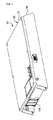
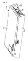
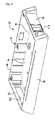
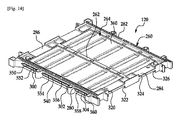
図1乃至図6を参照すると、本発明の一実施例に係る電池パック10が提供される。電池パック10は、電池パックハウジング30、電池モジュール34、熱伝導性ハウジング38、DC/DC電圧コンバータ42、及び電気ファン(electric fan)46を含んでいる。電池パック10の利点は、前記電池パック10が、電池セルに接触している熱交換器の内部に空気が向かうように内部電池セルを通って延びたエンドプレート230,232と共に電池モジュール34を含んでいるという点である。したがって、電池パック10は、電池セルに接触している熱交換器の内部に空気が向かうようにするための別途の空気マニホールドを必要としない。また、電池モジュール34の利点は、前記電池モジュール34が、それぞれの側面に2つの電池セルを固定する少なくとも1つのフレーム部材を使用し、電池セル冷却用統合冷却マニホールドを含むという点である。
1 to 6, a
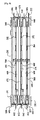
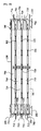
図1、図2及び図5を参照すると、電池パックハウジング30は、内部に電池パック10の残りの構成要素を固定するように形成されている。電池パックハウジング30は、内部領域74を形成するベース部70及び上端カバー72を含んでいる。内部領域74は、内部空間76及び内部空間78を含んでいる。
Referring to FIGS. 1, 2, and 5, the
図5を参照すると、ベース部70は下部壁90及び側壁92,94,96,98を含んでいる。側壁92,94,96,98は、下部壁90に連結されており、前記下部壁90に対して実質的に垂直であり、上部方向に延びている。側壁92,94は、互いに実質的に平行に延びている。また、側壁96,98は、互いに実質的に平行であり、側壁92,94に対して垂直に延びている。側壁92は、貫通延長された流入口112を含んでおり、側壁94は、貫通延長された排出口114を含んでいる。一実施例において、ベース部70は鉄又はアルミニウムからなっている。他の実施例において、ベース部70はプラスチックからなっている。
Referring to FIG. 5, the
上端カバー72は、内部領域74を取り囲むように、側壁92,94,96,98に除去可能に連結されている。一実施例において、上端カバー72は鉄又はアルミニウムからなっている。他の実施例において、上端カバー72はプラスチックからなっている。
The
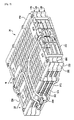
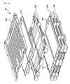
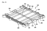
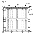
図5乃至図11を参照すると、電池モジュール34は、流入口112に隣接して、電池パックハウジング30の内部領域74の内部空間76内に位置している。電池モジュール34は、フレーム部材120,124,128、絶縁層140、電池セル150,154,158,162,166,170,180,184,188,192,196,200、電池セル相互接続アセンブリ220,222、及びエンドプレート230,232を含んでいる。
5 to 11, the
図7、図9、及び図10を参照すると、フレーム部材120,124,128は、電池セル150〜200を内部に固定するように形成されている。フレーム部材124は、フレーム部材120,128の間に連結されている。それぞれのフレーム部材120,124,128の構造は互いに同一である。したがって、フレーム部材120の構造のみを以下で詳細に説明する。
Referring to FIGS. 7, 9, and 10, the
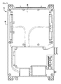
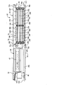
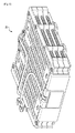
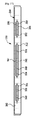
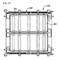
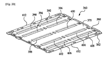
図14乃至図21を参照すると、フレーム部材120は、実質的に矩形リング状の外側プラスチックフレーム260、中央プラスチック壁262,263、及び熱交換器264を含んでいる。熱交換器264は、互いに連結されており、貫通延長された流路部540を形成する第1及び第2熱伝導性プレート360,362を含んでいる。図17を参照すると、流路部540は、第1及び第2熱伝導性プレート360,362をそれぞれ貫通して延びた下位流路部550,552,554,556,558,560を含んでいる。
14 to 21, the
図14乃至図16を参照すると、実質的に矩形リング状の外側プラスチックフレーム260は、第1及び第2熱伝導性プレート360,362の外周領域の周囲に連結されている。実質的に矩形リング状の第1外側プラスチックフレーム360は、第1、第2、第3、及び第4側壁280,282,284,286を含んでいる。第1及び第2側壁280,282は、実質的に互いに平行に延びている。第3及び第4側壁284,286は、第1側壁280と第2側壁282との間に連結され、第1及び第2側壁280,282に垂直になるように実質的に互いに平行に延びている。
Referring to FIGS. 14 to 16, a substantially rectangular ring-shaped outer
中央プラスチック壁262は、第1及び第2側壁280,282に実質的に平行に第3側壁284と第4側壁286との間に延びている。中央プラスチック壁262は、熱交換器264の熱伝導性プレート360の第1側380(図20参照)の部位上に位置している。
The central
中央プラスチック壁263は、第1及び第2側壁280,282に実質的に平行に第3側壁284と第4側壁286との間に延びている。中央プラスチック壁263は、熱交換器264の熱伝導性プレート362の第1側480(図22参照)の部位上に位置している。
The central
第1、第3、及び第4側壁280,284,286及び中央プラスチック壁262は、内部に電池セルを収容する領域を形成する。第2、第3、及び第4側壁282,284,286は、内部に他の電池セルを収容する領域を形成する。
The first, third, and
第1側壁280は、貫通延長された溝300,302,304を含んでいる。溝300は下位流路部550,552と流体連通する。また、溝302は下位流路部554,556と流体連通する。また、溝304は下位流路部558,560と流体連通する。
The
図17を参照すると、第2側壁282は、貫通延長された溝310,312,314を含んでいる。溝310は下位流路部550,552と流体連通する。また、溝312は下位流路部554,556と流体連通する。また、溝314は下位流路部558,560と流体連通する。
Referring to FIG. 17, the
図14及び図15を参照すると、第3側壁284は、内部に延びたグルーブ320,322,324,326を含んでいる。第4側壁286は、内部に延びたグルーブ330,332,334,336を含んでいる。グルーブ320,330は、それを貫通する電池セルの第1及び第2電極端子を収容するように構成されている。また、グルーブ324,334は、それを貫通する他の電池セルの第1及び第2電極端子を収容するように構成されている。また、グルーブ322,332は、それを貫通するさらに他の電池セルの第1及び第2電極端子を収容するように構成されている。最後に、グルーブ326,336は、それを貫通するさらに他の電池セルの第1及び第2電極端子を収容するように構成されている。
14 and 15, the
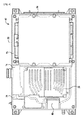
図20乃至図22を参照すると、熱交換器264は、互いに連結されている第1及び第2熱伝導性プレート360,362を含んでおり、前記プレート360,362を完全に貫通して延びる流路部540を形成している。
Referring to FIGS. 20-22, the
第1熱伝導性プレート360は、第1側380及び第2側382を備えたシート部370を含んでいる。シート部370は、長く伸びた湾入部390,392,394,396,398,400,402,404,406,408、及び湾入端部410,412を含んでいる。一実施例において、シート部370はアルミニウムからなっており、実質的に矩形状である。
The first thermally
第2熱伝導性プレート362は、第1側480及び第2側482を備えたシート部470を含んでいる。シート部470は、長く伸びた湾入部490,492,494,496,498,500,502,504,506,508、及び湾入端部510,512を含んでいる。一実施例において、シート部470はアルミニウムからなっており、実質的に矩形状である。
The second thermally
第1熱伝導性プレート360は、長く伸びた湾入部390,392,394,396,398,400,402,404,406,408が長く伸びた湾入部490,492,494,496,498,500,502,504,506,508にそれぞれ接触及び連結され、湾入端部410,412が湾入端部510,512に接触及び連結されるように第2熱伝導性プレート362に連結されている。前記プレート360,362は、前記プレート360,362の縦の長さに沿って完全に延びた下位流路部550,552,554,556,558,560を備えた流路部540を形成する。
The first heat
図7を参照すると、フレーム部材124は、上述したフレーム部材120と同一の構造を含んでいる。フレーム部材124は、実質的に矩形リング状の外側プラスチックフレーム570、第1及び第2中央プラスチック壁(図示せず)、及び熱交換器572を含んでいる。
Referring to FIG. 7, the
フレーム部材128は、上述したフレーム部材120と同一の構造を含んでいる。フレーム部材128は、実質的に矩形リング状の外側プラスチックフレーム580、第1及び第2中央プラスチック壁(図示せず)、及び熱交換器582を含んでいる。
The
図6、図9、及び図10を参照すると、フレーム部材120とエンドプレート232は、内部に電池セル150,180を固定するように構成されている。また、フレーム部材120の熱交換器264は、電池セル150,154の間に位置して接触している。また、熱交換器264は、電池セル180,184の間に位置して接触している。
Referring to FIGS. 6, 9, and 10, the
フレーム部材120,124は、内部に電池セル154,158を固定するように構成されている。また、フレーム部材120,124は、内部に電池セル184,188を固定するように構成されている。フレーム部材124の熱交換器572は、電池セル158,162の間に位置して接触している。また、熱交換器572は、電池セル188,192の間に位置して接触している。
The
フレーム部材124,128は、内部に電池セル162,166を固定するように構成されている。また、フレーム部材124,128は、内部に電池セル192,196を固定するように構成されている。フレーム部材128の熱交換器582は、電池セル166,170の間に位置して接触している。また、熱交換器582は、電池セル196,200の間に位置して接触している。
The
フレーム部材128と絶縁層140(図9参照)は、内部に電池セル170,200を固定するように構成されている。フレーム部材128の熱交換器582は、電池セル170,200に対向して位置している。エンドプレート230は、絶縁層140がフレーム部材128と電池セル170,200との間に位置するように、フレーム部材128に連結されている。
The
電池セル150,154,158,162,166,170,180,184,188,192,196,200は、それぞれ作動電圧を発生させるように構成されている。一実施例において、電池セル150〜200は、実質的に矩形のボディー部及び一対の電極端子を含んでいるパウチ型リチウムイオン電池セルである。一実施例において、電池セル150〜200は、電池セル相互接続及び電圧センシングアセンブリ220,222上の相互接続部材を用いて互いに電気的に直列接続されている。また、一実施例において、電池セル150〜200の電極端子は、超音波溶接機を用いて前記電池セル150〜200の電極端子を対応する相互接続部材に超音波溶接することによって、対応する相互接続部材に接続される。
The
図9を参照すると、電池セル150は、矩形状のハウジング640、及び前記ハウジング640の第1及び第2端部からそれぞれ延びた電極端子642,644を含んでいる。電極端子642は、電気的及び物理的に電池セル相互接続及び電圧センシングアセンブリ220に接続されている。電極端子644は、電気的及び物理的に電池セル相互接続及び電圧センシングアセンブリ222に接続されている。
Referring to FIG. 9, the
電池セル154は、矩形状のハウジング650、及び前記ハウジング650の第1及び第2端部からそれぞれ延びた電極端子652,654を含んでいる。電極端子652は、電気的及び物理的に電池セル相互接続及び電圧センシングアセンブリ220に接続されている。電極端子654は、電気的及び物理的に電池セル相互接続及び電圧センシングアセンブリ222に接続されている。
The
電池セル158は、矩形状のハウジング660、及び前記ハウジング660の第1及び第2端部からそれぞれ延びた電極端子662,664を含んでいる。電極端子662は、電気的及び物理的に電池セル相互接続及び電圧センシングアセンブリ220に接続されている。電極端子664は、電気的及び物理的に電池セル相互接続及び電圧センシングアセンブリ222に接続されている。
The
電池セル162は、矩形状のハウジング670、及び前記ハウジング670の第1及び第2端部からそれぞれ延びた電極端子672,674を含んでいる。電極端子672は、電気的及び物理的に電池セル相互接続及び電圧センシングアセンブリ220に接続されている。電極端子674は、電気的及び物理的に電池セル相互接続及び電圧センシングアセンブリ222に接続されている。
The
電池セル166は、矩形状のハウジング680、及び前記ハウジング680の第1及び第2端部からそれぞれ延びた電極端子682,684を含んでいる。電極端子682は、電気的及び物理的に電池セル相互接続及び電圧センシングアセンブリ220に接続されている。電極端子684は、電気的及び物理的に電池セル相互接続及び電圧センシングアセンブリ222に接続されている。
The
電池セル170は、矩形状のハウジング690、及び前記ハウジング690の第1及び第2端部からそれぞれ延びた電極端子692,694を含んでいる。電極端子692は、電気的及び物理的に電池セル相互接続及び電圧センシングアセンブリ220に接続されている。電極端子694は、電気的及び物理的に電池セル相互接続及び電圧センシングアセンブリ222に接続されている。
The
電池セル150〜170の直列結合体は、長く伸びた相互接続部材を用いて電池セル180〜200の直列結合体と電気的に直列接続されている。
The series combination of the
図10を参照すると、電池セル180は、矩形状のハウジング700、及び前記ハウジング700の第1及び第2端部からそれぞれ延びた電極端子702,704を含んでいる。電極端子702は、電気的及び物理的に電池セル相互接続及び電圧センシングアセンブリ220に接続されている。電極端子704は、電気的及び物理的に電池セル相互接続及び電圧センシングアセンブリ222に接続されている。
Referring to FIG. 10, the
電池セル184は、矩形状のハウジング710、及び前記ハウジング710の第1及び第2端部からそれぞれ延びた電極端子712,714を含んでいる。電極端子712は、電気的及び物理的に電池セル相互接続及び電圧センシングアセンブリ220に接続されている。電極端子714は、電気的及び物理的に電池セル相互接続及び電圧センシングアセンブリ222に接続されている。
The
電池セル188は、矩形状のハウジング720、及び前記ハウジング720の第1及び第2端部からそれぞれ延びた電極端子722,724を含んでいる。電極端子722は、電気的及び物理的に電池セル相互接続及び電圧センシングアセンブリ220に接続されている。電極端子724は、電気的及び物理的に電池セル相互接続及び電圧センシングアセンブリ222に接続されている。
The
電池セル192は、矩形状のハウジング730、及び前記ハウジング730の第1及び第2端部からそれぞれ延びた電極端子732,734を含んでいる。電極端子732は、電気的及び物理的に電池セル相互接続及び電圧センシングアセンブリ220に接続されている。電極端子734は、電気的及び物理的に電池セル相互接続及び電圧センシングアセンブリ222に接続されている。
The
電池セル196は、矩形状のハウジング740、及び前記ハウジング740の第1及び第2端部からそれぞれ延びた電極端子742,744を含んでいる。電極端子742は、電気的及び物理的に電池セル相互接続及び電圧センシングアセンブリ220に接続されている。電極端子744は、電気的及び物理的に電池セル相互接続及び電圧センシングアセンブリ222に接続されている。
The
電池セル200は、矩形状のハウジング750、及び前記ハウジング750の第1及び第2端部からそれぞれ延びた電極端子752,754を含んでいる。電極端子752は、電気的及び物理的に電池セル相互接続及び電圧センシングアセンブリ220に接続されている。電極端子754は、電気的及び物理的に電池セル相互接続及び電圧センシングアセンブリ222に接続されている。
The
図6を参照すると、エンドプレート230,232は、フレーム部材120,124,128の流路部540,574,584を介して冷却空気をそれぞれ案内するように形成されている。エンドプレート230,232は、フレーム部材120〜128、及び内部に位置した電池セル150〜200を含んでいる。
Referring to FIG. 6, the
エンドプレート230は、電池モジュール34の縦軸(longitudinal axis)768に実質的に平行に延びている。エンドプレート230は、第1エンド部(end portion)770及び第2エンド部772を含んでいる。第1エンド部770は、それぞれの電池セル150〜170の第1エンドを通って流入口112に向かって縦に延びている。第2エンド部772は、それぞれの電池セル180〜200の第2エンドを通って縦に延びている。
The
エンドプレート232は、電池モジュール34の縦軸768に実質的に平行に延びている。エンドプレート232は、第1エンド部780及び第2エンド部782を含んでいる。第1エンド部780は、それぞれの電池セル150〜170の第1エンドを通って流入口112に向かって縦に延びている。第2エンド部782は、それぞれの電池セル180〜200の第2エンドを通って縦に延びている。
The
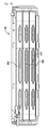
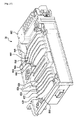
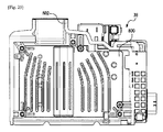
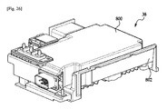
図5、図6及び図23乃至図26を参照すると、熱伝導性ハウジング38は、電池モジュール34の電池セルに電気的に接続されたDC/DC電圧コンバータ42を内部に固定するように形成されている。熱伝導性ハウジング38は、DC/DC電圧コンバータ42から熱伝導性ハウジングを通って流れる空気に熱を伝達する。熱伝導性ハウジング38は、電池モジュール34と電池パックハウジング30の排出口114との間で電池パックハウジング30の内部領域74の内部空間78内に位置する。熱伝導性ハウジング38は、熱伝導性ハウジング38と電池パックハウジング30との間に流路部804を形成する。流路部804は、電池モジュール34の流路部540,574,584及び排出口114と流体連通している。
Referring to FIGS. 5, 6, and 23 to 26, the heat
熱伝導性ハウジング38は、ハウジング部800及びフレーム部材802を含んでいる。ハウジング部800は、下部壁810、及び前記下部壁810から第1方向に外側に延びた冷却フィン820,822,824,826,840,842,844,846,848を含んでいる。冷却フィン820〜848は、流路部804が前記冷却フィン820〜848の間に形成されるように互いに離隔している。冷却フィン820〜848は、ベース部70の下部壁90(図5参照)上に位置している。一実施例において、熱伝導性ハウジング38はアルミニウムからなっている。勿論、他の実施例において、熱伝導性ハウジング38は、例えば、鉄又は他の金属合金のような他の材料からなってもよい。
The thermally
図6及び図23を参照すると、フレーム部材802は、熱伝導性ハウジング38の外部に連結されており、空気をファン46及び電池パックハウジング30の排出口114に案内する排出部870を含んでいる。
Referring to FIGS. 6 and 23, the
図5及び図6を参照すると、電気ファン46は、電池パックハウジング30の排出口114に隣接して、電池パックハウジング30の内部領域74内に位置している。電気ファン46は、空気が流入口112、電池モジュールの流路部540,574,584、流路部804、電気ファン46部位及び電池パックハウジング30の排出口114に沿って流れるように構成されている。他の実施例において、電気ファン46は、流入口112に隣接して位置している。
Referring to FIGS. 5 and 6, the
図6、図14、図16、図17及び図27を参照すると、本発明の他の実施例に係る電池モジュール部位の組立方法のフローチャートが提供される。 Referring to FIGS. 6, 14, 16, 17, and 27, a flowchart of a method for assembling a battery module according to another embodiment of the present invention is provided.
ステップ900において、使用者は電池セル154,184を準備する。ステップ900の後に、方法はステップ902に進む。
In
ステップ902において、使用者は、実質的に矩形リング状の外側プラスチックフレーム260及び熱交換器264を備えたフレーム部材を準備する。熱交換器264は、互いに連結されており、貫通延長された流路部540(図17参照)を形成する第1及び第2熱伝導性プレートを含んでいる。流路部540は、少なくとも第1及び第2熱伝導性プレート360,362をそれぞれ貫通して延びた下位流路部554,558を含んでいる。実質的に矩形リング状の外側プラスチックフレーム260は、前記第1及び第2熱伝導性プレート360,362の外周領域の周囲に連結されている。実質的に矩形リング状の外側プラスチックフレーム260は第1、第2、第3及び第4側壁280,282,284,286を含んでいる。第1及び第2側壁280,282は、実質的に互いに平行に延びている。第3及び第4側壁284,286は、前記第1側壁280と第2側壁282との間に連結されて、第1及び第2側壁280,282に垂直になるように実質的に互いに平行に延びている。第1側壁280は、下位流路部554,558と連通するように貫通延長された溝302,304(図14参照)をそれぞれ含んでいる。第2側壁282は、下位流路部554,558と連通するように貫通延長された溝312,314(図17参照)をそれぞれ含んでいる。ステップ902の後に、方法はステップ904に進む。
In
ステップ904において、使用者は、熱交換器264の第1熱伝導性プレート360の第1側に対向して電池セル154を位置させる。ステップ904の後に、方法はステップ906に進む。
In
ステップ906において、使用者は、熱交換器264の第1熱伝導性プレート360の第1側に対向して電池セル184を位置させる。電池セル184は、電池セル154に隣接して位置する。ステップ906の後に、方法はステップ908に進む。
In
ステップ908において、使用者は、電池セル158,188と熱交換器572を備えたフレーム部材124を準備する。ステップ908の後に、方法はステップ910に進む。
In
ステップ910において、使用者は、電池セル154に対向して電池セル158を位置させる。ステップ910の後に、方法はステップ912に進む。
In
ステップ912において、使用者は、電池セル184に対向して電池セル188を位置させる。ステップ912の後に、方法はステップ914に進む。
In
ステップ914において、使用者は、電池セル158,188上に熱交換器572を位置させる。
In step 914, the user positions the
図2、図6及び図28を参照すると、本発明の更に他の実施例に係る電池パック10の組立方法のフローチャートが提供される。
2, 6, and 28, a flowchart of a method for assembling the
ステップ930において、使用者は、電池パックハウジング30、電池モジュール34、熱伝導性ハウジング38、及び電気ファン46を準備する。電池パックハウジング30は内部領域74を形成する。電池パックハウジング30は、前記内部領域74と連通する流入口112及び排出口114をさらに含んでいる。電池モジュール34は、電池セル154、熱交換器264、及びエンドプレート230,232を含んでいる。電池セル154及び熱交換器264は、互いに対向して位置しており、エンドプレート230,232の間に位置している。熱交換器264は貫通状流路部540を形成している。電池セル154は第1エンド及び第2エンドを含んでいる。エンドプレート230は、電池モジュール34の縦軸768に実質的に平行に延びている。エンドプレート230は第1エンド部770及び第2エンド部772を含んでいる。エンドプレート230の第1エンド部770は、電池セル154の第1エンドを通って縦に延びている。エンドプレート230の第2エンド部772は、電池セル154の第2エンドを通って縦に延びている。エンドプレート232は、電池モジュール34の縦軸768に実質的に平行に延びている。エンドプレート232は第1エンド部780及び第2エンド部782を含んでいる。エンドプレート232の第1エンド部780は、電池セル154の第1エンドを通って縦に延びている。エンドプレート232の第2エンド部782は、電池セル154の第2エンドを通って縦に延びている。ステップ930の後に、方法はステップ932に進む。
In
ステップ932において、使用者は、流入口112に隣接して電池パックハウジング30の内部領域74内に電池モジュール34を位置させる。ステップ932の後に、方法はステップ934に進む。
In
ステップ934において、使用者は、電池モジュール34と電池パックハウジング30の排出口114との間で電池パックハウジング30の内部領域74内に熱伝導性ハウジング38を位置させる。熱伝導性ハウジング38は、熱伝導性ハウジング38と電池パックハウジング30との間に流路部804を形成している。流路部804は流路部540と流体連通する。ステップ934の後に、方法はステップ936に進む。
In
ステップ936において、使用者は、電池パックハウジング30の排出口114に隣接して、電池パックハウジング30の内部領域74内に電気ファン46を位置させる。電気ファン46は、空気が流入口114、流路部540,804、電気ファン46部位及び電池パックハウジング30の排出口114に沿って流れるように構成されている。
In
電池モジュール及び電池モジュールの組立方法は、他の電池モジュール及び方法に比べて実質的な利点を提供する。具体的に、前記電池モジュールは、それぞれの側面に2つの電池セルを固定する少なくとも1つのフレーム部材を使用し、電池セル冷却用統合冷却マニホールドを含む。 Battery modules and battery module assembly methods provide substantial advantages over other battery modules and methods. Specifically, the battery module includes at least one frame member that fixes two battery cells on each side surface, and includes an integrated cooling manifold for cooling battery cells.
たとえ、本発明は、単に制限された数の例示にのみ関連して具体的に記述されたが、本発明が、上記に表現された例示のみに限定されるものではない点を認識しなければならない。また、本発明は、変形、変更、置換、またはここに表現されたものだけでなく、本発明の意図と範疇に適するように、相応する組み合わせにいくらでも修正可能である。さらに、たとえ、本発明の様々な例示が表現されたが、本発明の様態は、単に表現された例示の一部のみを含むことができるという点を認識しなければならない。したがって、本発明は、上記の表現によって限定されるものではない。 Although the present invention has been specifically described in connection with only a limited number of examples, it should be recognized that the present invention is not limited to only the examples expressed above. Don't be. Moreover, the present invention is not limited to variations, changes, substitutions, or what is expressed herein, but can be modified in any number of suitable combinations to suit the spirit and scope of the present invention. Further, although various examples of the present invention have been expressed, it should be recognized that aspects of the present invention may include only a portion of the expressed examples. Accordingly, the present invention is not limited by the above expression.
以上で説明したように、本発明に係る電池モジュール及び電池モジュールの組立方法は、他の電池モジュール及び方法に比べて実質的な利点を提供する。具体的に、前記電池モジュールは、それぞれの側面に2つの電池セルを固定する少なくとも1つのフレーム部材を使用し、電池セル冷却用統合冷却マニホールドを含む。 As described above, the battery module and the battery module assembly method according to the present invention provide substantial advantages compared to other battery modules and methods. Specifically, the battery module includes at least one frame member that fixes two battery cells on each side surface, and includes an integrated cooling manifold for cooling battery cells.
34 電池モジュール
120、124、128 フレーム部材
264、572、582 熱交換器
360 第1熱伝導性プレート
362 第2熱伝導性プレート
570、580 外側プラスチックフレーム
34
Claims (11)
実質的に矩形リング状の第1外側プラスチックフレーム及び第1熱交換器(heat exchanger)を備えた第1フレーム部材と、を含み、
前記第1熱交換器は、互いに連結されており、貫通延長された第1流路部(flow path portion)を形成する第1及び第2熱伝導性プレートを含み、前記第1流路部は、少なくとも前記第1及び第2熱伝導性プレートをそれぞれ貫通して延びた第1及び第2下位流路部(flow path subportions)を含み、
前記実質的に矩形リング状の第1外側プラスチックフレームは、前記第1及び第2熱伝導性プレートの外周領域(outer peripheral region)の周囲に連結されており、前記実質的に矩形リング状の第1外側プラスチックフレームは第1、第2、第3及び第4側壁を含んでおり、前記第1及び第2側壁は、実質的に互いに平行に延びており、前記第3及び第4側壁は、第1側壁と第2側壁との間に連結されており、実質的に互いに平行に延びており、第1及び第2側壁に垂直であり、前記第1側壁は、それぞれ第1及び第2下位流路部と連通するように貫通延長された第1及び第2溝(apertures)を含んでおり、前記第2側壁は、それぞれ第1及び第2下位流路部と連通するように貫通延長された第3及び第4溝をそれぞれ含んでおり、
前記第1電池セルは、第1熱伝導性プレートの第1側(side)に対向して位置しており、
前記第2電池セルは、第1熱伝導性プレートの第1側に対向して位置しており、また、第1電池セルに隣接して位置していることを特徴とする、電池モジュール。 First and second battery cells;
A first frame member with a substantially rectangular ring-shaped first outer plastic frame and a first heat exchanger;
The first heat exchanger includes first and second heat conductive plates that are connected to each other and form a first flow path portion that extends through the first heat exchanger. The first flow path portion includes: At least first and second lower flow paths extending through the first and second thermal conductive plates, respectively.
The substantially rectangular ring-shaped first outer plastic frame is connected to a periphery of an outer peripheral region of the first and second heat conductive plates, and the substantially rectangular ring-shaped first outer plastic frame is connected to the outer peripheral region. 1 The outer plastic frame includes first, second, third and fourth sidewalls, the first and second sidewalls extending substantially parallel to each other, and the third and fourth sidewalls are Connected between the first side wall and the second side wall, extending substantially parallel to each other and perpendicular to the first and second side walls, wherein the first side wall is a first and second subordinate respectively. It includes first and second apertures that extend through to communicate with the flow path, and the second side walls are extended through to communicate with the first and second lower flow paths, respectively. 3rd and 3rd It includes respective grooves,
The first battery cell is located opposite to the first side of the first thermal conductive plate;
The battery module, wherein the second battery cell is located opposite to the first side of the first thermal conductive plate and is located adjacent to the first battery cell.
前記第1電池セルは、第1、第3及び第4側壁、及び中央プラスチック壁によって設定された第1区域(region)内で第1熱伝導性プレートの第1側に対向して位置しており、
前記第2電池セルは、第2、第3及び第4側壁、及び中央プラスチック壁によって設定された第2区域内で、第1電池セルに隣接した第1熱伝導性プレートの第1側に対向して位置していることを特徴とする、請求項1に記載の電池モジュール。 The first frame member further includes a central plastic wall extending between the third and fourth sidewalls substantially parallel to the first and second sidewalls, the central plastic wall comprising: Located on a portion of the first side of the thermally conductive plate;
The first battery cell is located opposite to the first side of the first thermally conductive plate in a first region set by first, third and fourth sidewalls and a central plastic wall. And
The second battery cell faces the first side of the first thermally conductive plate adjacent to the first battery cell in a second area set by the second, third and fourth sidewalls and the central plastic wall. The battery module according to claim 1, wherein the battery module is positioned as follows.
前記第1エンドプレートは、電池モジュールの縦軸(longitudinal axis)に実質的に平行に延びており、第1エンドプレートは第1エンド部(end portion)及び第2エンド部を含んでおり、第1エンドプレートの第1エンド部は、第1電池セルの第1エンドと第2電池セルの第1エンドを通って縦に延びており、第1エンドプレートの第2エンド部は、第1電池セルの第2エンドと第2電池セルの第2エンドを通って縦に延びており、
前記第2エンドプレートは、電池モジュールの縦軸に実質的に平行に延びており、第2エンドプレートは第1エンド部及び第2エンド部を含んでおり、第2エンドプレートの第1エンド部は、第1電池セルの第1エンドと第2電池セルの第1エンドを通って縦に延びており、第2エンドプレートの第2エンド部は、第1電池セルの第2エンドと第2電池セルの第2エンドを通って縦に延びていることを特徴とする、請求項1に記載の電池モジュール。 The battery module further includes first and second end plates, and the first and second battery cells and the first frame member are between the first end plate and the second end plate. The first battery cell includes first and second ends (ends), the second battery cell includes first and second ends,
The first end plate extends substantially parallel to a longitudinal axis of the battery module. The first end plate includes a first end portion and a second end portion. The first end portion of the one end plate extends vertically through the first end of the first battery cell and the first end of the second battery cell, and the second end portion of the first end plate is the first battery. Extending vertically through the second end of the cell and the second end of the second battery cell;
The second end plate extends substantially parallel to the longitudinal axis of the battery module, the second end plate includes a first end portion and a second end portion, and the first end portion of the second end plate Extends vertically through the first end of the first battery cell and the first end of the second battery cell, and the second end portion of the second end plate has the second end of the first battery cell and the second end of the second battery cell. The battery module according to claim 1, wherein the battery module extends vertically through the second end of the battery cell.
第1及び第2電池セルを準備する過程と、
実質的に矩形リング状の第1外側プラスチックフレーム及び第1熱交換器を備えた第1フレーム部材であって、前記第1熱交換器は、互いに連結されており、貫通延長された第1流路部を形成する第1及び第2熱伝導性プレートを含み、前記第1流路部は、少なくとも前記第1及び第2熱伝導性プレートをそれぞれ貫通して延びた第1及び第2下位流路部を含み、前記実質的に矩形リング状の第1外側プラスチックフレームは、前記第1及び第2熱伝導性プレートの外周領域の周囲に連結されており、前記実質的に矩形リング状の第1外側プラスチックフレームは第1、第2、第3及び第4側壁を含んでおり、前記第1及び第2側壁は、実質的に互いに平行に延びており、第3及び第4側壁は、前記第1側壁と第2側壁との間に連結されて、第1及び第2側壁に垂直になるように実質的に互いに平行に延びており、前記第1側壁は、第1及び第2下位流路部と連通するように貫通延長された第1及び第2溝をそれぞれ含んでおり、前記第2側壁は、第1及び第2下位流路部と連通するように貫通延長された第3及び第4溝をそれぞれ含んでいる、第1フレーム部材を準備する過程と、
前記第1電池セルを第1熱伝導性プレートの第1側に対向して位置させる過程と、
前記第2電池セルを第1電池セルに隣接して、第1熱伝導性プレートに対向するように位置させる過程と、
を含むことを特徴とする、電池モジュールの組立方法。 A battery module assembly method comprising:
Preparing the first and second battery cells;
A first frame member comprising a substantially rectangular ring-shaped first outer plastic frame and a first heat exchanger, wherein the first heat exchanger is connected to each other and extends through the first flow. First and second thermal conductive plates forming a path portion, wherein the first flow path portion extends at least through the first and second thermal conductive plates, respectively. The substantially rectangular ring-shaped first outer plastic frame including a path is connected to the periphery of the outer peripheral area of the first and second heat conductive plates, and the substantially rectangular ring-shaped first outer plastic frame The outer plastic frame includes first, second, third and fourth side walls, the first and second side walls extending substantially parallel to each other, and the third and fourth side walls Connected between the first side wall and the second side wall; The first side wall and the second side wall extend substantially parallel to each other so as to be perpendicular to the first and second side walls, and the first side wall extends through the first and second lower flow paths so as to communicate therewith. A first frame member is provided, each including a groove, wherein the second side wall includes a third and a fourth groove extending through and extending so as to communicate with the first and second lower flow paths, respectively. Process,
Positioning the first battery cell opposite the first side of the first thermally conductive plate;
Positioning the second battery cell adjacent to the first battery cell so as to face the first thermally conductive plate;
A method for assembling a battery module, comprising:
第3及び第4電池セルと第2フレーム部材を準備する過程であって、前記第2フレーム部材は、実質的に矩形リング状の第2外側プラスチックフレーム及び第2熱交換器を備えている、過程と、
前記第3電池セルを第1電池セルに対向して位置させる過程と、
前記第4電池セルを第2電池セルに対向して位置させる過程と、
前記第2熱交換器を第3及び第4電池セル上に位置させる過程と、
をさらに含むことを特徴とする、請求項10に記載の電池モジュールの組立方法。 The method
In the process of preparing the third and fourth battery cells and the second frame member, the second frame member includes a substantially rectangular ring-shaped second outer plastic frame and a second heat exchanger. Process,
Positioning the third battery cell opposite the first battery cell;
Positioning the fourth battery cell opposite to the second battery cell;
Positioning the second heat exchanger on the third and fourth battery cells;
The battery module assembling method according to claim 10, further comprising:
Applications Claiming Priority (3)
| Application Number | Priority Date | Filing Date | Title |
|---|---|---|---|
| US14/273,586 | 2014-05-09 | ||
| US14/273,586 US10770762B2 (en) | 2014-05-09 | 2014-05-09 | Battery module and method of assembling the battery module |
| PCT/KR2015/004505 WO2015170870A1 (en) | 2014-05-09 | 2015-05-06 | Battery module and method for assembling battery module |
Publications (2)
| Publication Number | Publication Date |
|---|---|
| JP2017517841A true JP2017517841A (en) | 2017-06-29 |
| JP6824551B2 JP6824551B2 (en) | 2021-02-03 |
Family
ID=54368593
Family Applications (1)
| Application Number | Title | Priority Date | Filing Date |
|---|---|---|---|
| JP2016564154A Active JP6824551B2 (en) | 2014-05-09 | 2015-05-06 | Battery module and how to assemble the battery module |
Country Status (6)
| Country | Link |
|---|---|
| US (1) | US10770762B2 (en) |
| EP (1) | EP3121893B1 (en) |
| JP (1) | JP6824551B2 (en) |
| KR (1) | KR101968718B1 (en) |
| CN (1) | CN106575805B (en) |
| WO (1) | WO2015170870A1 (en) |
Cited By (1)
| Publication number | Priority date | Publication date | Assignee | Title |
|---|---|---|---|---|
| EP3686960A1 (en) | 2019-01-24 | 2020-07-29 | TDK Corporation | Battery pack |
Families Citing this family (5)
| Publication number | Priority date | Publication date | Assignee | Title |
|---|---|---|---|---|
| US9966641B2 (en) | 2015-12-29 | 2018-05-08 | Lg Chem, Ltd. | Battery pack |
| CN105762314B (en) * | 2016-04-15 | 2019-01-08 | 宁德时代新能源科技股份有限公司 | Battery cell buffer structure and battery pack adopting same |
| CN106627199A (en) * | 2016-11-02 | 2017-05-10 | 上海钧希新能源科技有限公司 | Fixing structure for vehicle-mounted level fuel battery control panel |
| WO2018218502A1 (en) * | 2017-05-31 | 2018-12-06 | 宁德时代新能源科技股份有限公司 | Fixing frame, battery module, and battery pack |
| KR102868277B1 (en) * | 2021-11-18 | 2025-10-10 | 주식회사 엘지에너지솔루션 | Pouch-type Battery Cell Comprising Sensing Member and Battery Module Comprising the Same |
Citations (6)
| Publication number | Priority date | Publication date | Assignee | Title |
|---|---|---|---|---|
| JP2011510449A (en) * | 2008-01-18 | 2011-03-31 | エルジー・ケム・リミテッド | Battery cell assembly and method for assembling the battery cell assembly |
| KR101069161B1 (en) * | 2008-06-30 | 2011-09-30 | 주식회사 엘지화학 | Battery module having a cooling manifold and cooling method of the battery module |
| KR20120088020A (en) * | 2010-10-12 | 2012-08-08 | 삼성에스디아이 주식회사 | Battery unit and battery module |
| KR20130017289A (en) * | 2011-08-10 | 2013-02-20 | 현대자동차주식회사 | Side air bag apparatus for vehicle |
| WO2013031613A1 (en) * | 2011-08-26 | 2013-03-07 | 三洋電機株式会社 | Power supply device, vehicle provided with same, and power storage device |
| KR20130033531A (en) * | 2011-09-27 | 2013-04-04 | 에스케이이노베이션 주식회사 | Battery module |
Family Cites Families (260)
| Publication number | Priority date | Publication date | Assignee | Title |
|---|---|---|---|---|
| DE436922C (en) | 1923-06-18 | 1926-11-11 | Fried Krupp Akt Ges Germaniawe | Cooling device for accumulator cells |
| US2391859A (en) | 1931-11-07 | 1946-01-01 | Hoover Co | Room cooling device |
| GB481891A (en) | 1936-09-18 | 1938-03-18 | India Rubber Gutta Percha Tele | Improvements in or relating to containers for electric storage cells |
| US2210833A (en) | 1937-10-28 | 1940-08-06 | Gen Tire & Rubber Co | Sealing gasket |
| US2273244A (en) | 1940-04-03 | 1942-02-17 | Electric Storage Battery Co | Storage battery cell |
| SE319224B (en) | 1966-12-19 | 1970-01-12 | Asea Ab | |
| US3503558A (en) | 1968-03-14 | 1970-03-31 | Electrolux Corp | Exhaust diffusion manifold for a vacuum cleaner or the like |
| US3550681A (en) | 1968-12-30 | 1970-12-29 | Gen Motors Corp | Self-adjusting thermal connector |
| US4009752A (en) | 1975-02-24 | 1977-03-01 | Honeywell Information Systems Inc. | Warp-resistant heat sink |
| US3964930A (en) | 1975-07-21 | 1976-06-22 | United Technologies Corporation | Fuel cell cooling system |
| US4063590A (en) | 1976-10-22 | 1977-12-20 | Mcconnell Christopher L | Preheater for clothes dryer |
| US4305456A (en) | 1977-08-12 | 1981-12-15 | Paul Mueller Company | Condenser and hot water system |
| US4298904A (en) | 1979-12-17 | 1981-11-03 | The Boeing Company | Electronic conduction cooling clamp |
| US4337626A (en) | 1980-05-01 | 1982-07-06 | Tyler Refrigeration Corporation | Well type refrigerated case with defrost air intake and colliding band air defrost |
| US4322776A (en) | 1980-08-04 | 1982-03-30 | Hughes Aircraft Company | Thermal interconnection |
| US4444994A (en) | 1982-01-29 | 1984-04-24 | Varo, Inc. | Electrically insulated quick disconnect heat sink |
| US4518663A (en) | 1983-07-01 | 1985-05-21 | Energy Development Associates, Inc. | Electrolyte circulation subsystem |
| GB8329269D0 (en) | 1983-11-02 | 1983-12-07 | British Aerospace | Electronic apparatus stowage |
| US4777561A (en) | 1985-03-26 | 1988-10-11 | Hughes Aircraft Company | Electronic module with self-activated heat pipe |
| FR2580433B1 (en) | 1985-04-16 | 1987-08-14 | Socapex | THERMAL CONNECTOR FOR PRINTED CIRCUIT BOARD COATED WITH ELECTRONIC COMPONENTS |
| US4849858A (en) | 1986-10-20 | 1989-07-18 | Westinghouse Electric Corp. | Composite heat transfer means |
| US4995240A (en) | 1987-01-27 | 1991-02-26 | Eaton Corporation | Controlling refrigeration having control module directly attached on valve body |
| US5057968A (en) | 1989-10-16 | 1991-10-15 | Lockheed Corporation | Cooling system for electronic modules |
| US4982785A (en) | 1990-03-06 | 1991-01-08 | Inter-City Products Corporation (Usa) | Serpentine heat exchanger |
| US5186250A (en) | 1990-05-11 | 1993-02-16 | Showa Aluminum Kabushiki Kaisha | Tube for heat exchangers and a method for manufacturing the tube |
| US5071652A (en) | 1990-12-11 | 1991-12-10 | Globe-Union Inc. | Metal oxide hydrogen battery having improved heat transfer properties |
| CH679620A5 (en) | 1990-12-11 | 1992-03-13 | Sulzer Ag | |
| US5392873A (en) | 1992-01-22 | 1995-02-28 | Honda Giken Kogyo Kabushiki Kaisha | Structure for securing batteries used in an electric vehicle |
| US5214564A (en) | 1992-04-23 | 1993-05-25 | Sunstrand Corporation | Capacitor assembly with integral cooling apparatus |
| FR2697677B1 (en) | 1992-11-02 | 1994-12-30 | Europ Accumulateurs | Thermoregulated storage battery, especially for electric vehicles. |
| JP2903913B2 (en) | 1992-11-10 | 1999-06-14 | 松下電器産業株式会社 | Storage battery system |
| US5275012A (en) | 1993-01-07 | 1994-01-04 | Ford Motor Company | Climate control system for electric vehicle |
| US5356735A (en) | 1993-05-10 | 1994-10-18 | General Motors Corporation | Heated/cooled battery |
| US5329988A (en) | 1993-05-28 | 1994-07-19 | The Allen Group, Inc. | Heat exchanger |
| US5520976A (en) | 1993-06-30 | 1996-05-28 | Simmonds Precision Products Inc. | Composite enclosure for electronic hardware |
| US5472802A (en) | 1993-10-25 | 1995-12-05 | Ovonic Battery Company, Inc. | Sealed hydride batteries, including a new lid-terminal seal and electrode tab collecting comb |
| US5663007A (en) | 1994-02-23 | 1997-09-02 | Matsushita Electric Industrial Co., Ltd. | Sealed storage battery and method for manufacturing the same |
| JP3260951B2 (en) | 1994-02-23 | 2002-02-25 | 松下電器産業株式会社 | Single cell and unit cell of sealed alkaline storage battery |
| US5346786A (en) | 1994-03-21 | 1994-09-13 | Hodgetts Philip J | Modular rack mounted battery system |
| JPH08111244A (en) | 1994-10-12 | 1996-04-30 | Nissan Motor Co Ltd | Stacked battery device |
| JP3451141B2 (en) | 1994-11-14 | 2003-09-29 | 本田技研工業株式会社 | Battery temperature controller |
| JP3451142B2 (en) | 1994-11-18 | 2003-09-29 | 本田技研工業株式会社 | Battery assembly with temperature control mechanism |
| US5620057A (en) | 1994-12-19 | 1997-04-15 | General Motors Corporation | Electric vehicle battery enclosure |
| US5586444A (en) | 1995-04-25 | 1996-12-24 | Tyler Refrigeration | Control for commercial refrigeration system |
| US5678421A (en) | 1995-12-26 | 1997-10-21 | Habco Beverage Systems Inc. | Refrigeration unit for cold space merchandiser |
| JP3745424B2 (en) | 1995-11-06 | 2006-02-15 | 東芝電池株式会社 | Battery manufacturing method |
| JPH09199186A (en) | 1996-01-22 | 1997-07-31 | Toyota Autom Loom Works Ltd | Storage battery cooling structure, storage battery module using storage battery cooling structure and storage battery cooling method |
| JPH09219213A (en) | 1996-02-09 | 1997-08-19 | Nissan Motor Co Ltd | Secondary battery for electric vehicle and its temperature rise alleviation device |
| JP3225192B2 (en) | 1996-04-10 | 2001-11-05 | 本田技研工業株式会社 | Battery exhaust gas control system |
| DE19639115C2 (en) | 1996-09-24 | 2003-08-07 | Behr Gmbh & Co | Plate-shaped heat transfer element |
| US5816062A (en) | 1997-01-15 | 1998-10-06 | Yu Feng Enterprise Co., Ltd. | Air conditioning system with supplemental ice storing and cooling capacity |
| JP3240973B2 (en) | 1997-03-05 | 2001-12-25 | トヨタ自動車株式会社 | Battery cooling system for vehicles |
| EP1030389B1 (en) | 1997-03-24 | 2003-01-08 | Matsushita Electric Industrial Co., Ltd. | Battery housing with integrated cables for voltage measuring |
| US6087036A (en) | 1997-07-25 | 2000-07-11 | 3M Innovative Properties Company | Thermal management system and method for a solid-state energy storing device |
| JP3830243B2 (en) | 1997-10-06 | 2006-10-04 | トヨタ自動車株式会社 | Battery power supply |
| JP3790946B2 (en) | 1997-12-08 | 2006-06-28 | 株式会社ヴァレオサーマルシステムズ | Heat exchanger |
| FR2774215B1 (en) | 1998-01-29 | 2000-02-25 | Alsthom Cge Alcatel | WATERPROOF MONOBLOCK BATTERY PROVIDED WITH A COOLING DEVICE |
| EP0948065B1 (en) | 1998-03-30 | 2003-06-04 | Renata AG | Safety vent for accumulator or battery |
| US7264901B2 (en) | 1998-08-23 | 2007-09-04 | Ovonic Battery Company, Inc. | Monoblock battery |
| US6255015B1 (en) | 1998-08-23 | 2001-07-03 | Ovonic Battery Company, Inc. | Monoblock battery assembly |
| JP4231127B2 (en) | 1998-09-03 | 2009-02-25 | パナソニック株式会社 | Integrated battery temperature control method and apparatus |
| US6176095B1 (en) | 1999-01-19 | 2001-01-23 | Carrier Corporation | Pretrip device for testing of a refrigeration system compressor |
| JP5025039B2 (en) | 1999-07-07 | 2012-09-12 | 株式会社日本自動車部品総合研究所 | Battery temperature control device |
| JP4778602B2 (en) | 1999-07-22 | 2011-09-21 | パナソニック株式会社 | Secondary battery |
| JP4416266B2 (en) | 1999-10-08 | 2010-02-17 | パナソニック株式会社 | Sealed prismatic battery |
| JP4252172B2 (en) | 1999-10-12 | 2009-04-08 | 株式会社日本自動車部品総合研究所 | Battery cooling system |
| US6399238B1 (en) | 1999-12-13 | 2002-06-04 | Alcatel | Module configuration |
| JP4921629B2 (en) | 2000-03-31 | 2012-04-25 | パナソニック株式会社 | Fluid-cooled battery pack system |
| US6560980B2 (en) | 2000-04-10 | 2003-05-13 | Thermo King Corporation | Method and apparatus for controlling evaporator and condenser fans in a refrigeration system |
| JP3777981B2 (en) | 2000-04-13 | 2006-05-24 | トヨタ自動車株式会社 | Vehicle power supply |
| WO2001080333A1 (en) | 2000-04-13 | 2001-10-25 | Fmc Corporation | Battery pack or battery providing increased heat dissipation |
| DE10021161A1 (en) | 2000-04-29 | 2001-10-31 | Vb Autobatterie Gmbh | Method for determining the state of charge and the load capacity of an electric accumulator |
| JP4116238B2 (en) | 2000-05-19 | 2008-07-09 | 株式会社タイカ | Thermally conductive sheet having electromagnetic shielding properties |
| US6462949B1 (en) | 2000-08-07 | 2002-10-08 | Thermotek, Inc. | Electronic enclosure cooling system |
| JP3727840B2 (en) | 2000-09-29 | 2005-12-21 | 株式会社東芝 | Battery pack and portable electronic device |
| JP3576092B2 (en) | 2000-11-10 | 2004-10-13 | 松下冷機株式会社 | refrigerator |
| JP3616005B2 (en) | 2000-12-20 | 2005-02-02 | 本田技研工業株式会社 | Hybrid vehicle cooling system |
| FR2819036B1 (en) | 2001-01-04 | 2004-01-16 | Cit Alcatel | VALVE AND ELECTROCHEMICAL GENERATOR COMPRISING SUCH A VALVE |
| US6569556B2 (en) | 2001-01-29 | 2003-05-27 | General Motors Corporation | Cooling system for a battery pack |
| JP4892788B2 (en) | 2001-04-23 | 2012-03-07 | トヨタ自動車株式会社 | Battery module |
| US6422027B1 (en) | 2001-05-03 | 2002-07-23 | Ford Global Tech., Inc. | System and method for cooling a battery pack |
| CN1194436C (en) | 2001-05-11 | 2005-03-23 | 上海神力科技有限公司 | Improved fuel cell |
| US6506111B2 (en) | 2001-05-16 | 2003-01-14 | Sanmina-Sci Corporation | Cooling airflow distribution device |
| JP4361229B2 (en) | 2001-07-04 | 2009-11-11 | 日産自動車株式会社 | Battery system |
| JP3850688B2 (en) | 2001-07-19 | 2006-11-29 | 松下電器産業株式会社 | Cooling device for prismatic battery and battery pack |
| US6512347B1 (en) | 2001-10-18 | 2003-01-28 | General Motors Corporation | Battery having an integral cooling system |
| JP3969254B2 (en) | 2001-10-29 | 2007-09-05 | 株式会社デンソー | Battery temperature management device |
| JP2003188323A (en) | 2001-12-19 | 2003-07-04 | Sony Corp | Graphite sheet and method for producing the same |
| JP2005513403A (en) | 2001-12-21 | 2005-05-12 | ベール ゲーエムベーハー ウント コー カーゲー | Especially heat exchanger for automobile |
| KR20040082437A (en) | 2002-02-19 | 2004-09-24 | 쓰리엠 이노베이티브 프로퍼티즈 컴파니 | Temperature control apparatus and method for high energy electrochemical cells |
| US6821671B2 (en) | 2002-03-01 | 2004-11-23 | Lg Chem, Ltd. | Method and apparatus for cooling and positioning prismatic battery cells |
| JP2003282112A (en) | 2002-03-26 | 2003-10-03 | Denso Corp | Intermediate heat exchanger for fuel cells |
| JP3733079B2 (en) | 2002-03-29 | 2006-01-11 | 三洋電機株式会社 | Cold storage |
| JP4041334B2 (en) | 2002-04-08 | 2008-01-30 | 株式会社不二工機 | Expansion valve and refrigeration cycle |
| US6889762B2 (en) | 2002-04-29 | 2005-05-10 | Bergstrom, Inc. | Vehicle air conditioning and heating system providing engine on and engine off operation |
| JP4242665B2 (en) | 2002-05-13 | 2009-03-25 | パナソニック株式会社 | Battery pack cooling device and secondary battery |
| KR100471233B1 (en) | 2002-06-26 | 2005-03-10 | 현대자동차주식회사 | Method of generating maximum charge current and maximum discharge current for battery in a hybrid electric vehicle |
| CA2392610C (en) | 2002-07-05 | 2010-11-02 | Long Manufacturing Ltd. | Baffled surface cooled heat exchanger |
| US7010644B2 (en) | 2002-08-29 | 2006-03-07 | Micron Technology, Inc. | Software refreshed memory device and method |
| CA2445622C (en) | 2002-10-18 | 2011-06-28 | Habco Beverage Systems Inc. | Modular refrigeration unit and refrigerator |
| US7070874B2 (en) | 2002-12-24 | 2006-07-04 | Fuelcell Energy, Inc. | Fuel cell end unit with integrated heat exchanger |
| AU2004216063B2 (en) | 2003-02-27 | 2009-02-19 | Protonex Technology Corporation | Externally manifolded membrane based electrochemical cell stacks |
| JP3867060B2 (en) | 2003-03-28 | 2007-01-10 | 三菱電機株式会社 | Vehicle power supply system |
| JP2004333115A (en) | 2003-04-16 | 2004-11-25 | Showa Denko Kk | Heat exchanger and method of manufacturing the same |
| TWI309290B (en) | 2003-05-30 | 2009-05-01 | Sanyo Electric Co | Cooling apparatus |
| US20050026014A1 (en) | 2003-07-31 | 2005-02-03 | Michael Fogaing | Polymer batteries having thermal exchange apparatus |
| JP4045340B2 (en) | 2003-08-13 | 2008-02-13 | 現代自動車株式会社 | Battery effective power calculation method and calculation system |
| JP4578867B2 (en) | 2003-09-30 | 2010-11-10 | 株式会社日立製作所 | Hydrogen storage / supply device and system thereof, distributed power source using the same, and automobile |
| US7270910B2 (en) | 2003-10-03 | 2007-09-18 | Black & Decker Inc. | Thermal management systems for battery packs |
| US6826948B1 (en) | 2003-10-09 | 2004-12-07 | Delphi Technologies, Inc. | Leak detection apparatus for a liquid circulation cooling system |
| JP3972884B2 (en) * | 2003-10-10 | 2007-09-05 | 日産自動車株式会社 | Assembled battery |
| JP4078553B2 (en) | 2003-10-21 | 2008-04-23 | 新神戸電機株式会社 | Lithium battery module for vehicles |
| JP2005147443A (en) | 2003-11-12 | 2005-06-09 | Calsonic Kansei Corp | Laminated type heat exchanger |
| JP3784813B2 (en) | 2003-11-26 | 2006-06-14 | 本田技研工業株式会社 | High-voltage cooling device for vehicle motor and hybrid vehicle |
| WO2005059427A1 (en) | 2003-12-17 | 2005-06-30 | Eaton Corporation | Fitting for fluid conveyance |
| US7237395B2 (en) | 2003-12-22 | 2007-07-03 | General Electric Company | Methods and apparatus for controlling refrigerators |
| KR100799866B1 (en) | 2004-03-16 | 2008-01-31 | 주식회사 엘지화학 | Secondary battery with excellent safety |
| JP4570888B2 (en) | 2004-03-18 | 2010-10-27 | 富士重工業株式会社 | Power storage device |
| JP2005349955A (en) | 2004-06-10 | 2005-12-22 | Toyota Motor Corp | Cooling structure of power storage mechanism |
| JP4707346B2 (en) | 2004-08-16 | 2011-06-22 | 三洋電機株式会社 | Power supply for vehicle |
| CA2583168C (en) | 2004-10-05 | 2013-01-29 | Nitto Denko Corporation | Fuel cell and power generating method |
| KR101088081B1 (en) | 2004-10-29 | 2011-11-30 | 한라공조주식회사 | heat transmitter |
| JP2006139928A (en) | 2004-11-10 | 2006-06-01 | Nissan Motor Co Ltd | Battery system |
| KR100637472B1 (en) | 2004-12-07 | 2006-10-23 | 삼성에스디아이 주식회사 | Secondary battery module |
| KR100876458B1 (en) | 2004-12-24 | 2008-12-29 | 주식회사 엘지화학 | Battery cartridge of novel structure and open battery module containing it |
| KR20070111456A (en) | 2005-02-02 | 2007-11-21 | 캐리어 코포레이션 | Heat exchanger due to fluid expansion in the header |
| JP2006236826A (en) | 2005-02-25 | 2006-09-07 | Toyota Motor Corp | Battery pack |
| MX2007011126A (en) | 2005-03-16 | 2007-11-13 | Ford Global Tech Llc | Power supply system. |
| US7716937B2 (en) | 2005-03-17 | 2010-05-18 | Electrolux Home Products, Inc. | Electronic refrigeration control system including a variable speed compressor |
| KR100965049B1 (en) | 2005-03-23 | 2010-06-21 | 에스케이에너지 주식회사 | Lamination Structure of High Power Lithium Secondary Battery Unit Cell |
| KR20060102853A (en) | 2005-03-25 | 2006-09-28 | 삼성에스디아이 주식회사 | Secondary battery module |
| US9653748B2 (en) | 2005-04-14 | 2017-05-16 | Enerdel, Inc. | Apparatus and method for securing battery cell packs |
| AU2006201260B2 (en) | 2005-04-19 | 2011-09-15 | Fisher & Paykel Appliances Limited | Linear Compressor Controller |
| US7278389B2 (en) | 2005-04-19 | 2007-10-09 | Murat Kirakosyan | Automobile intake air flow plenum and plenum diverter |
| KR100880386B1 (en) | 2005-06-03 | 2009-01-23 | 주식회사 엘지화학 | Secondary battery of novel structure and battery pack including same |
| JP4415910B2 (en) | 2005-07-12 | 2010-02-17 | トヨタ自動車株式会社 | Hybrid vehicle structure |
| KR100765659B1 (en) | 2005-08-09 | 2007-10-10 | 현대자동차주식회사 | Fuel cell stack structure for automobile |
| JP2007048750A (en) | 2005-08-10 | 2007-02-22 | Samsung Sdi Co Ltd | Battery module |
| JP4600212B2 (en) | 2005-08-23 | 2010-12-15 | 株式会社デンソー | Supercritical refrigeration cycle equipment |
| US7658224B2 (en) | 2005-09-19 | 2010-02-09 | Dana Canada Corporation | Flanged connection for heat exchanger |
| JP2007107684A (en) | 2005-10-17 | 2007-04-26 | Nsk Ltd | End cap of linear guide device |
| US20070087266A1 (en) | 2005-10-18 | 2007-04-19 | Debbi Bourke | Modular battery system |
| US8030886B2 (en) | 2005-12-21 | 2011-10-04 | Nuventix, Inc. | Thermal management of batteries using synthetic jets |
| KR100948003B1 (en) | 2006-02-27 | 2010-03-18 | 주식회사 엘지화학 | Medium and large battery packs with excellent cooling efficiency |
| US20070209378A1 (en) | 2006-03-10 | 2007-09-13 | Larson Gerald L | Vehicle integrated power and control strategy for cold plate refrigeration system |
| DE102006015568B3 (en) | 2006-04-04 | 2007-05-31 | Daimlerchrysler Ag | Process for the production of a heat exchanger module for heat exchangers for electrochemical energy storage, and device for carrying out the process |
| JP4857896B2 (en) | 2006-05-11 | 2012-01-18 | トヨタ自動車株式会社 | Battery pack and vehicle |
| DE102007028252B4 (en) | 2006-06-26 | 2017-02-02 | Denso Corporation | Refrigerant cycle device with ejector |
| CN101101997A (en) | 2006-07-05 | 2008-01-09 | 大同股份有限公司 | Fuel cell and method of assembling the same |
| JP2008054379A (en) | 2006-08-22 | 2008-03-06 | Calsonic Kansei Corp | Battery cooling system for vehicle |
| JP4251204B2 (en) | 2006-08-31 | 2009-04-08 | 日産自動車株式会社 | Battery module |
| JP2008062875A (en) | 2006-09-11 | 2008-03-21 | Calsonic Kansei Corp | Battery cooling system for vehicle |
| KR100921346B1 (en) | 2006-09-25 | 2009-10-13 | 주식회사 엘지화학 | Medium and large battery module and battery module assembly |
| JP2008080995A (en) | 2006-09-28 | 2008-04-10 | Denso Corp | Cooling system |
| US7531270B2 (en) | 2006-10-13 | 2009-05-12 | Enerdel, Inc. | Battery pack with integral cooling and bussing devices |
| KR100889241B1 (en) | 2006-10-23 | 2009-03-17 | 주식회사 엘지화학 | Electrode terminal connection member of battery module |
| US20080226976A1 (en) | 2006-11-01 | 2008-09-18 | Eveready Battery Company, Inc. | Alkaline Electrochemical Cell with Reduced Gassing |
| US7797958B2 (en) | 2006-11-15 | 2010-09-21 | Glacier Bay, Inc. | HVAC system controlled by a battery management system |
| KR101064240B1 (en) | 2006-11-27 | 2011-09-14 | 주식회사 엘지화학 | Power system with thermal radiation protection |
| JP2008159439A (en) | 2006-12-25 | 2008-07-10 | Toyota Motor Corp | Power storage module |
| JP2008159440A (en) | 2006-12-25 | 2008-07-10 | Calsonic Kansei Corp | Vehicular battery cooling system |
| US8268505B2 (en) | 2007-01-25 | 2012-09-18 | Honda Motor Co., Ltd. | Fuel cell system |
| DE102007004567A1 (en) | 2007-01-30 | 2008-07-31 | Robert Bosch Gmbh | Electrochemical cell e.g. coffee-bag cell, housing device for traction system of e.g. hybrid motor vehicle, has cell and lugs for contacting, where cell is enclosed between housing parts, which clamp cell between parts using pressing force |
| WO2008111162A1 (en) | 2007-03-13 | 2008-09-18 | Hoshizaki Denki Kabushiki Kaisha | Cooling storage chamber and method for operating the same |
| KR100942985B1 (en) | 2007-03-21 | 2010-02-17 | 주식회사 엘지화학 | Medium and large battery pack case with improved distribution uniformity of refrigerant flow rate |
| JP2008251378A (en) | 2007-03-30 | 2008-10-16 | Toyota Motor Corp | Battery pack cooling structure |
| KR101212362B1 (en) | 2007-04-04 | 2012-12-13 | 에스케이이노베이션 주식회사 | Temperature controller for electric vehicle using thermoelectric semiconductor |
| JP5236210B2 (en) | 2007-05-10 | 2013-07-17 | カルソニックカンセイ株式会社 | Battery module structure of the battery |
| US7846573B2 (en) | 2007-06-01 | 2010-12-07 | Cobasys, Llc | Coolant manifold |
| JP4438830B2 (en) | 2007-06-19 | 2010-03-24 | コニカミノルタビジネステクノロジーズ株式会社 | Resin composition, molded body, electrophotographic transfer belt, and image forming apparatus |
| KR101141057B1 (en) | 2007-06-28 | 2012-05-03 | 주식회사 엘지화학 | Middle or Large-sized Battery Pack |
| JP5137480B2 (en) | 2007-06-29 | 2013-02-06 | 三洋電機株式会社 | Power supply for vehicle |
| JP2009054297A (en) | 2007-08-23 | 2009-03-12 | Toshiba Corp | Battery pack |
| JP4508221B2 (en) | 2007-08-27 | 2010-07-21 | 豊田合成株式会社 | Battery assembly |
| DE102007045183A1 (en) | 2007-09-21 | 2009-04-02 | Robert Bosch Gmbh | Temperierte battery device and method for this purpose |
| KR100872225B1 (en) | 2007-11-05 | 2008-12-05 | 엘지전자 주식회사 | Refrigerator Control Method |
| WO2009061451A1 (en) * | 2007-11-07 | 2009-05-14 | Enerdel, Inc. | Battery assembly with temperature control device |
| KR100949334B1 (en) | 2007-11-12 | 2010-03-26 | 삼성에스디아이 주식회사 | Battery module |
| US9283826B2 (en) | 2007-11-13 | 2016-03-15 | Mahle International Gmbh | Device for cooling a heat source of a motor vehicle |
| US8409743B2 (en) | 2007-11-28 | 2013-04-02 | Sanyo Electric Co., Ltd. | Battery system with battery cells arranged in array alignment |
| JP5147373B2 (en) | 2007-11-29 | 2013-02-20 | 三洋電機株式会社 | Battery system |
| CN101904042B (en) | 2007-12-05 | 2014-11-05 | 埃纳德尔公司 | Battery pack with temperature control |
| JP2009158316A (en) | 2007-12-27 | 2009-07-16 | Calsonic Kansei Corp | Battery cooling device |
| DE102008011466A1 (en) | 2008-02-27 | 2009-09-03 | Robert Bosch Gmbh | battery module |
| CN101978549A (en) | 2008-03-24 | 2011-02-16 | 三洋电机株式会社 | Battery device and battery unit |
| JP5258348B2 (en) | 2008-03-27 | 2013-08-07 | 三洋電機株式会社 | Power supply for vehicle |
| KR20090107443A (en) | 2008-04-08 | 2009-10-13 | 쏘씨에떼 드 베이뀔르 엘렉트리끄 | An electric battery comprising a flexible power generation element and a mechanical and thermal control system of the power generation elements |
| US7851080B2 (en) | 2008-04-09 | 2010-12-14 | Gm Global Technology Operations, Inc. | Battery cooling plate design with discrete channels |
| US8465863B2 (en) | 2008-04-09 | 2013-06-18 | GM Global Technology Operations LLC | Batteries and components thereof and methods of making and assembling the same |
| US8215432B2 (en) | 2008-05-09 | 2012-07-10 | GM Global Technology Operations LLC | Battery thermal system for vehicle |
| US7883793B2 (en) * | 2008-06-30 | 2011-02-08 | Lg Chem, Ltd. | Battery module having battery cell assemblies with alignment-coupling features |
| US8067111B2 (en) | 2008-06-30 | 2011-11-29 | Lg Chem, Ltd. | Battery module having battery cell assembly with heat exchanger |
| US8486552B2 (en) | 2008-06-30 | 2013-07-16 | Lg Chem, Ltd. | Battery module having cooling manifold with ported screws and method for cooling the battery module |
| US9759495B2 (en) | 2008-06-30 | 2017-09-12 | Lg Chem, Ltd. | Battery cell assembly having heat exchanger with serpentine flow path |
| US9140501B2 (en) | 2008-06-30 | 2015-09-22 | Lg Chem, Ltd. | Battery module having a rubber cooling manifold |
| DE102008034860B4 (en) | 2008-07-26 | 2011-07-14 | Daimler AG, 70327 | Battery with a battery housing and a heat-conducting plate for tempering the battery |
| EP2200109B1 (en) | 2008-12-12 | 2015-01-07 | Behr GmbH & Co. KG | Holding and cooling device for a galvanic cell |
| DE102009005124A1 (en) | 2009-01-19 | 2010-07-29 | Li-Tec Battery Gmbh | Electrochemical energy storage device |
| DE102009005854A1 (en) | 2009-01-23 | 2010-07-29 | Li-Tec Battery Gmbh | Battery cell with enclosure |
| DE102009006426A1 (en) | 2009-01-28 | 2010-07-29 | Li-Tec Battery Gmbh | Battery with housing |
| EP2634028B1 (en) | 2009-03-30 | 2017-01-11 | MAHLE Behr GmbH & Co. KG | Device for the thermal connection of an energy storage device |
| US9337456B2 (en) | 2009-04-20 | 2016-05-10 | Lg Chem, Ltd. | Frame member, frame assembly and battery cell assembly made therefrom and methods of making the same |
| US8663829B2 (en) | 2009-04-30 | 2014-03-04 | Lg Chem, Ltd. | Battery systems, battery modules, and method for cooling a battery module |
| US8852778B2 (en) | 2009-04-30 | 2014-10-07 | Lg Chem, Ltd. | Battery systems, battery modules, and method for cooling a battery module |
| US20100275619A1 (en) | 2009-04-30 | 2010-11-04 | Lg Chem, Ltd. | Cooling system for a battery system and a method for cooling the battery system |
| US8403030B2 (en) | 2009-04-30 | 2013-03-26 | Lg Chem, Ltd. | Cooling manifold |
| ITBO20090427A1 (en) | 2009-07-02 | 2011-01-03 | Ferrari Spa | ELECTRIC TRACTION VEHICLE WITH COOLING THROUGH REFRIGERATED CYCLE |
| US8399118B2 (en) | 2009-07-29 | 2013-03-19 | Lg Chem, Ltd. | Battery module and method for cooling the battery module |
| US8703318B2 (en) | 2009-07-29 | 2014-04-22 | Lg Chem, Ltd. | Battery module and method for cooling the battery module |
| US8399119B2 (en) | 2009-08-28 | 2013-03-19 | Lg Chem, Ltd. | Battery module and method for cooling the battery module |
| JP4877373B2 (en) | 2009-08-28 | 2012-02-15 | 日産自動車株式会社 | Assembled battery and manufacturing method of assembled battery |
| KR20110024954A (en) | 2009-09-03 | 2011-03-09 | 삼성전자주식회사 | Secondary Battery Module with Cooling Channel |
| JP5496604B2 (en) * | 2009-10-30 | 2014-05-21 | 三洋電機株式会社 | Power supply device and vehicle equipped with the same |
| KR101093959B1 (en) | 2010-02-04 | 2011-12-15 | 에스비리모티브 주식회사 | Heat sink in battery module |
| KR101230954B1 (en) | 2010-04-08 | 2013-02-07 | 주식회사 엘지화학 | Battery Module Having Sensing Member with Novel Structure |
| DE102010020065A1 (en) * | 2010-05-11 | 2011-11-17 | Bayerische Motoren Werke Aktiengesellschaft | Energy storage module of several prismatic memory cells and method for producing an energy storage module |
| KR101205180B1 (en) | 2010-05-18 | 2012-11-27 | 주식회사 엘지화학 | Cooling Member of Compact Structure and Excellent Stability and Battery Module Employed with the Same |
| CN203351708U (en) | 2010-05-21 | 2013-12-18 | 格拉弗技术国际控股有限公司 | Battery pack |
| EP2390951A1 (en) | 2010-05-26 | 2011-11-30 | MANN+HUMMEL GmbH | Heat transfer module for battery cells and battery assembly therewith |
| US9065158B2 (en) | 2010-05-28 | 2015-06-23 | GM Global Technology Operations LLC | Corrugated fin and frame assembly for battery cooling |
| US8460815B2 (en) | 2010-05-28 | 2013-06-11 | GM Global Technology Operations LLC | Stackable repeating frame with integrated cell sensing connection |
| DE102010021922A1 (en) | 2010-05-28 | 2011-12-01 | Li-Tec Battery Gmbh | Cooling element and method for producing the same; electrochemical energy storage device with cooling element |
| KR101156527B1 (en) | 2010-06-01 | 2012-06-21 | 에스비리모티브 주식회사 | Battery pack |
| JP5464168B2 (en) | 2010-06-04 | 2014-04-09 | 株式会社デンソー | Power supply |
| US9196938B2 (en) | 2010-07-06 | 2015-11-24 | Samsung Sdi Co., Ltd. | Battery module |
| DE102010032899A1 (en) | 2010-07-30 | 2012-02-02 | Valeo Klimasysteme Gmbh | Cooling device for a vehicle battery and vehicle battery assembly with such a cooling device |
| US8673473B2 (en) | 2010-08-10 | 2014-03-18 | GM Global Technology Operations LLC | Integrated cooling fin and frame |
| JP5606872B2 (en) | 2010-08-20 | 2014-10-15 | 愛三工業株式会社 | Battery module |
| US8662153B2 (en) * | 2010-10-04 | 2014-03-04 | Lg Chem, Ltd. | Battery cell assembly, heat exchanger, and method for manufacturing the heat exchanger |
| CN201859929U (en) | 2010-10-27 | 2011-06-08 | 法雷奥汽车空调湖北有限公司 | Power battery cooling and heating device for electric automobile |
| KR101252944B1 (en) | 2011-03-08 | 2013-04-15 | 로베르트 보쉬 게엠베하 | Battery pack with enhanced radiating ability |
| KR101247462B1 (en) | 2011-05-20 | 2013-03-25 | 세방전지(주) | Battery pack for battery cooling |
| JP5484403B2 (en) * | 2011-06-08 | 2014-05-07 | 本田技研工業株式会社 | Battery module |
| KR101469518B1 (en) | 2011-08-01 | 2014-12-05 | 주식회사 엘지화학 | Battery Module of Improved Stability |
| CN203950871U (en) | 2011-08-15 | 2014-11-19 | 格拉弗技术国际控股有限公司 | battery pack components |
| US8974938B2 (en) | 2011-08-30 | 2015-03-10 | Lg Chem, Ltd. | Battery system and method for coupling a battery cell assembly to an electrically non-conductive base member |
| KR101883915B1 (en) | 2011-09-30 | 2018-08-02 | 삼성에스디아이 주식회사 | Battery module having support member |
| US8512890B2 (en) | 2011-11-07 | 2013-08-20 | Bren-Tronics Batteries International, L.L.C. | Lithium ion cell with cooling features |
| KR20130054715A (en) | 2011-11-17 | 2013-05-27 | 삼성전기주식회사 | Battery pack case |
| JP5768683B2 (en) | 2011-11-28 | 2015-08-26 | 富士通株式会社 | Reception data processing method, communication apparatus, and program |
| KR101750066B1 (en) | 2011-12-02 | 2017-06-23 | 에스케이이노베이션 주식회사 | Water-cooled type secondary battery |
| KR101382011B1 (en) | 2011-12-23 | 2014-04-15 | 세방전지(주) | Secondary battery pack |
| US9105950B2 (en) | 2012-03-29 | 2015-08-11 | Lg Chem, Ltd. | Battery system having an evaporative cooling member with a plate portion and a method for cooling the battery system |
| US9379420B2 (en) | 2012-03-29 | 2016-06-28 | Lg Chem, Ltd. | Battery system and method for cooling the battery system |
| CN103367830B (en) * | 2012-05-17 | 2016-01-20 | 奇鋐科技股份有限公司 | Water-cooled plate unit for battery packs |
| US8852781B2 (en) | 2012-05-19 | 2014-10-07 | Lg Chem, Ltd. | Battery cell assembly and method for manufacturing a cooling fin for the battery cell assembly |
| KR101987773B1 (en) | 2012-07-16 | 2019-06-11 | 에스케이이노베이션 주식회사 | Battery pack |
| US9960395B2 (en) | 2012-08-16 | 2018-05-01 | Lg Chem, Ltd. | Battery module |
| US9306199B2 (en) | 2012-08-16 | 2016-04-05 | Lg Chem, Ltd. | Battery module and method for assembling the battery module |
| US20140120390A1 (en) | 2012-10-31 | 2014-05-01 | Lg Chem, Ltd. | Battery cell assembly and method for manufacturing a cooling fin for the battery cell assembly |
| US9083066B2 (en) | 2012-11-27 | 2015-07-14 | Lg Chem, Ltd. | Battery system and method for cooling a battery cell assembly |
| US8852783B2 (en) | 2013-02-13 | 2014-10-07 | Lg Chem, Ltd. | Battery cell assembly and method for manufacturing the battery cell assembly |
| KR101572447B1 (en) | 2013-03-19 | 2015-11-27 | 주식회사 엘지화학 | Voltage Sensing Member and Battery Module Employed with the Same |
| US9647292B2 (en) | 2013-04-12 | 2017-05-09 | Lg Chem, Ltd. | Battery cell assembly and method for manufacturing a cooling fin for the battery cell assembly |
| JP6089980B2 (en) | 2013-06-03 | 2017-03-08 | 株式会社デンソー | Battery cooling device |
| US9184424B2 (en) | 2013-07-08 | 2015-11-10 | Lg Chem, Ltd. | Battery assembly |
| US9444124B2 (en) | 2014-01-23 | 2016-09-13 | Lg Chem, Ltd. | Battery cell assembly and method for coupling a cooling fin to first and second cooling manifolds |
| US9484559B2 (en) | 2014-10-10 | 2016-11-01 | Lg Chem, Ltd. | Battery cell assembly |
| US9412980B2 (en) | 2014-10-17 | 2016-08-09 | Lg Chem, Ltd. | Battery cell assembly |
| US9786894B2 (en) | 2014-11-03 | 2017-10-10 | Lg Chem, Ltd. | Battery pack |
-
2014
- 2014-05-09 US US14/273,586 patent/US10770762B2/en active Active
-
2015
- 2015-05-06 KR KR1020167029113A patent/KR101968718B1/en active Active
- 2015-05-06 JP JP2016564154A patent/JP6824551B2/en active Active
- 2015-05-06 EP EP15789675.4A patent/EP3121893B1/en active Active
- 2015-05-06 WO PCT/KR2015/004505 patent/WO2015170870A1/en not_active Ceased
- 2015-05-06 CN CN201580021308.7A patent/CN106575805B/en active Active
Patent Citations (6)
| Publication number | Priority date | Publication date | Assignee | Title |
|---|---|---|---|---|
| JP2011510449A (en) * | 2008-01-18 | 2011-03-31 | エルジー・ケム・リミテッド | Battery cell assembly and method for assembling the battery cell assembly |
| KR101069161B1 (en) * | 2008-06-30 | 2011-09-30 | 주식회사 엘지화학 | Battery module having a cooling manifold and cooling method of the battery module |
| KR20120088020A (en) * | 2010-10-12 | 2012-08-08 | 삼성에스디아이 주식회사 | Battery unit and battery module |
| KR20130017289A (en) * | 2011-08-10 | 2013-02-20 | 현대자동차주식회사 | Side air bag apparatus for vehicle |
| WO2013031613A1 (en) * | 2011-08-26 | 2013-03-07 | 三洋電機株式会社 | Power supply device, vehicle provided with same, and power storage device |
| KR20130033531A (en) * | 2011-09-27 | 2013-04-04 | 에스케이이노베이션 주식회사 | Battery module |
Cited By (2)
| Publication number | Priority date | Publication date | Assignee | Title |
|---|---|---|---|---|
| EP3686960A1 (en) | 2019-01-24 | 2020-07-29 | TDK Corporation | Battery pack |
| US11489217B2 (en) | 2019-01-24 | 2022-11-01 | Tdk Corporation | Battery pack |
Also Published As
| Publication number | Publication date |
|---|---|
| EP3121893B1 (en) | 2018-07-04 |
| JP6824551B2 (en) | 2021-02-03 |
| WO2015170870A1 (en) | 2015-11-12 |
| KR20170003535A (en) | 2017-01-09 |
| CN106575805B (en) | 2019-03-08 |
| KR101968718B1 (en) | 2019-04-12 |
| US20150325823A1 (en) | 2015-11-12 |
| CN106575805A (en) | 2017-04-19 |
| US10770762B2 (en) | 2020-09-08 |
| EP3121893A4 (en) | 2017-01-25 |
| EP3121893A1 (en) | 2017-01-25 |
Similar Documents
| Publication | Publication Date | Title |
|---|---|---|
| JP6612779B2 (en) | Battery pack and method of assembling it | |
| CN107258027B (en) | Battery pack | |
| JP6374603B2 (en) | Battery pack | |
| JP6824551B2 (en) | Battery module and how to assemble the battery module | |
| CN107546351B (en) | first sub-base | |
| JP6423890B2 (en) | Battery module | |
| JP6124512B2 (en) | Battery module | |
| KR102002043B1 (en) | Secondary battery module and Secondary battery pack | |
| TWI765076B (en) | Battery packs and power batteries | |
| JP2015135763A (en) | Power storage device | |
| CN105324885A (en) | battery pack | |
| CN108023135A (en) | Rechargeable battery and rechargeable battery module | |
| CN106663852B (en) | The method of battery pack and the electric fan in control battery pack | |
| JP2017106672A (en) | Heat radiator and manufacturing method of heat radiator | |
| JP2018530136A (en) | Battery system and assembly method thereof | |
| JP2017517850A (en) | Battery pack and method of controlling an electric fan provided in the battery pack | |
| JP2021508924A (en) | Electrochemical cell cover with improved thermal conductivity | |
| TWM573900U (en) | Battery component and power battery | |
| JP7123351B2 (en) | battery pack |
Legal Events
| Date | Code | Title | Description |
|---|---|---|---|
| A621 | Written request for application examination |
Free format text: JAPANESE INTERMEDIATE CODE: A621 Effective date: 20170922 |
|
| A131 | Notification of reasons for refusal |
Free format text: JAPANESE INTERMEDIATE CODE: A131 Effective date: 20181203 |
|
| A521 | Request for written amendment filed |
Free format text: JAPANESE INTERMEDIATE CODE: A523 Effective date: 20190227 |
|
| A02 | Decision of refusal |
Free format text: JAPANESE INTERMEDIATE CODE: A02 Effective date: 20190805 |
|
| A521 | Request for written amendment filed |
Free format text: JAPANESE INTERMEDIATE CODE: A523 Effective date: 20191205 |
|
| C60 | Trial request (containing other claim documents, opposition documents) |
Free format text: JAPANESE INTERMEDIATE CODE: C60 Effective date: 20191205 |
|
| A911 | Transfer to examiner for re-examination before appeal (zenchi) |
Free format text: JAPANESE INTERMEDIATE CODE: A911 Effective date: 20191213 |
|
| C21 | Notice of transfer of a case for reconsideration by examiners before appeal proceedings |
Free format text: JAPANESE INTERMEDIATE CODE: C21 Effective date: 20191216 |
|
| A912 | Re-examination (zenchi) completed and case transferred to appeal board |
Free format text: JAPANESE INTERMEDIATE CODE: A912 Effective date: 20200214 |
|
| C211 | Notice of termination of reconsideration by examiners before appeal proceedings |
Free format text: JAPANESE INTERMEDIATE CODE: C211 Effective date: 20200225 |
|
| C22 | Notice of designation (change) of administrative judge |
Free format text: JAPANESE INTERMEDIATE CODE: C22 Effective date: 20200615 |
|
| C13 | Notice of reasons for refusal |
Free format text: JAPANESE INTERMEDIATE CODE: C13 Effective date: 20200803 |
|
| A521 | Request for written amendment filed |
Free format text: JAPANESE INTERMEDIATE CODE: A523 Effective date: 20201027 |
|
| C23 | Notice of termination of proceedings |
Free format text: JAPANESE INTERMEDIATE CODE: C23 Effective date: 20201116 |
|
| C03 | Trial/appeal decision taken |
Free format text: JAPANESE INTERMEDIATE CODE: C03 Effective date: 20201214 |
|
| C30A | Notification sent |
Free format text: JAPANESE INTERMEDIATE CODE: C3012 Effective date: 20201214 |
|
| A61 | First payment of annual fees (during grant procedure) |
Free format text: JAPANESE INTERMEDIATE CODE: A61 Effective date: 20210106 |
|
| R150 | Certificate of patent or registration of utility model |
Ref document number: 6824551 Country of ref document: JP Free format text: JAPANESE INTERMEDIATE CODE: R150 |
|
| S111 | Request for change of ownership or part of ownership |
Free format text: JAPANESE INTERMEDIATE CODE: R313111 |
|
| R350 | Written notification of registration of transfer |
Free format text: JAPANESE INTERMEDIATE CODE: R350 |
|
| R250 | Receipt of annual fees |
Free format text: JAPANESE INTERMEDIATE CODE: R250 |
|
| R250 | Receipt of annual fees |
Free format text: JAPANESE INTERMEDIATE CODE: R250 |
|
| R250 | Receipt of annual fees |
Free format text: JAPANESE INTERMEDIATE CODE: R250 |