JP2017506308A - Positive displacement rotary machine - Google Patents
Positive displacement rotary machine Download PDFInfo
- Publication number
- JP2017506308A JP2017506308A JP2016553361A JP2016553361A JP2017506308A JP 2017506308 A JP2017506308 A JP 2017506308A JP 2016553361 A JP2016553361 A JP 2016553361A JP 2016553361 A JP2016553361 A JP 2016553361A JP 2017506308 A JP2017506308 A JP 2017506308A
- Authority
- JP
- Japan
- Prior art keywords
- axis
- compressor
- pump
- inner element
- conical screw
- Prior art date
- Legal status (The legal status is an assumption and is not a legal conclusion. Google has not performed a legal analysis and makes no representation as to the accuracy of the status listed.)
- Pending
Links
Images


Classifications
-
- F—MECHANICAL ENGINEERING; LIGHTING; HEATING; WEAPONS; BLASTING
- F04—POSITIVE - DISPLACEMENT MACHINES FOR LIQUIDS; PUMPS FOR LIQUIDS OR ELASTIC FLUIDS
- F04C—ROTARY-PISTON, OR OSCILLATING-PISTON, POSITIVE-DISPLACEMENT MACHINES FOR LIQUIDS; ROTARY-PISTON, OR OSCILLATING-PISTON, POSITIVE-DISPLACEMENT PUMPS
- F04C15/00—Component parts, details or accessories of machines, pumps or pumping installations, not provided for in groups F04C2/00 - F04C14/00
- F04C15/0057—Driving elements, brakes, couplings, transmission specially adapted for machines or pumps
- F04C15/0061—Means for transmitting movement from the prime mover to driven parts of the pump, e.g. clutches, couplings, transmissions
-
- F—MECHANICAL ENGINEERING; LIGHTING; HEATING; WEAPONS; BLASTING
- F04—POSITIVE - DISPLACEMENT MACHINES FOR LIQUIDS; PUMPS FOR LIQUIDS OR ELASTIC FLUIDS
- F04C—ROTARY-PISTON, OR OSCILLATING-PISTON, POSITIVE-DISPLACEMENT MACHINES FOR LIQUIDS; ROTARY-PISTON, OR OSCILLATING-PISTON, POSITIVE-DISPLACEMENT PUMPS
- F04C18/00—Rotary-piston pumps specially adapted for elastic fluids
- F04C18/08—Rotary-piston pumps specially adapted for elastic fluids of intermeshing-engagement type, i.e. with engagement of co-operating members similar to that of toothed gearing
- F04C18/10—Rotary-piston pumps specially adapted for elastic fluids of intermeshing-engagement type, i.e. with engagement of co-operating members similar to that of toothed gearing of internal-axis type with the outer member having more teeth or tooth equivalents, e.g. rollers, than the inner member
- F04C18/107—Rotary-piston pumps specially adapted for elastic fluids of intermeshing-engagement type, i.e. with engagement of co-operating members similar to that of toothed gearing of internal-axis type with the outer member having more teeth or tooth equivalents, e.g. rollers, than the inner member with helical teeth
-
- F—MECHANICAL ENGINEERING; LIGHTING; HEATING; WEAPONS; BLASTING
- F04—POSITIVE - DISPLACEMENT MACHINES FOR LIQUIDS; PUMPS FOR LIQUIDS OR ELASTIC FLUIDS
- F04C—ROTARY-PISTON, OR OSCILLATING-PISTON, POSITIVE-DISPLACEMENT MACHINES FOR LIQUIDS; ROTARY-PISTON, OR OSCILLATING-PISTON, POSITIVE-DISPLACEMENT PUMPS
- F04C2/00—Rotary-piston machines or pumps
- F04C2/08—Rotary-piston machines or pumps of intermeshing-engagement type, i.e. with engagement of co-operating members similar to that of toothed gearing
- F04C2/10—Rotary-piston machines or pumps of intermeshing-engagement type, i.e. with engagement of co-operating members similar to that of toothed gearing of internal-axis type with the outer member having more teeth or tooth-equivalents, e.g. rollers, than the inner member
- F04C2/107—Rotary-piston machines or pumps of intermeshing-engagement type, i.e. with engagement of co-operating members similar to that of toothed gearing of internal-axis type with the outer member having more teeth or tooth-equivalents, e.g. rollers, than the inner member with helical teeth
- F04C2/1071—Rotary-piston machines or pumps of intermeshing-engagement type, i.e. with engagement of co-operating members similar to that of toothed gearing of internal-axis type with the outer member having more teeth or tooth-equivalents, e.g. rollers, than the inner member with helical teeth the inner and outer member having a different number of threads and one of the two being made of elastic materials, e.g. Moineau type
- F04C2/1076—Rotary-piston machines or pumps of intermeshing-engagement type, i.e. with engagement of co-operating members similar to that of toothed gearing of internal-axis type with the outer member having more teeth or tooth-equivalents, e.g. rollers, than the inner member with helical teeth the inner and outer member having a different number of threads and one of the two being made of elastic materials, e.g. Moineau type where one member orbits or wobbles relative to the other member which rotates around a fixed axis
-
- F—MECHANICAL ENGINEERING; LIGHTING; HEATING; WEAPONS; BLASTING
- F04—POSITIVE - DISPLACEMENT MACHINES FOR LIQUIDS; PUMPS FOR LIQUIDS OR ELASTIC FLUIDS
- F04C—ROTARY-PISTON, OR OSCILLATING-PISTON, POSITIVE-DISPLACEMENT MACHINES FOR LIQUIDS; ROTARY-PISTON, OR OSCILLATING-PISTON, POSITIVE-DISPLACEMENT PUMPS
- F04C29/00—Component parts, details or accessories of pumps or pumping installations, not provided for in groups F04C18/00 - F04C28/00
- F04C29/0042—Driving elements, brakes, couplings, transmissions specially adapted for pumps
- F04C29/005—Means for transmitting movement from the prime mover to driven parts of the pump, e.g. clutches, couplings, transmissions
-
- F—MECHANICAL ENGINEERING; LIGHTING; HEATING; WEAPONS; BLASTING
- F04—POSITIVE - DISPLACEMENT MACHINES FOR LIQUIDS; PUMPS FOR LIQUIDS OR ELASTIC FLUIDS
- F04C—ROTARY-PISTON, OR OSCILLATING-PISTON, POSITIVE-DISPLACEMENT MACHINES FOR LIQUIDS; ROTARY-PISTON, OR OSCILLATING-PISTON, POSITIVE-DISPLACEMENT PUMPS
- F04C2/00—Rotary-piston machines or pumps
- F04C2/08—Rotary-piston machines or pumps of intermeshing-engagement type, i.e. with engagement of co-operating members similar to that of toothed gearing
- F04C2/082—Details specially related to intermeshing engagement type machines or pumps
- F04C2/084—Toothed wheels
-
- F—MECHANICAL ENGINEERING; LIGHTING; HEATING; WEAPONS; BLASTING
- F04—POSITIVE - DISPLACEMENT MACHINES FOR LIQUIDS; PUMPS FOR LIQUIDS OR ELASTIC FLUIDS
- F04C—ROTARY-PISTON, OR OSCILLATING-PISTON, POSITIVE-DISPLACEMENT MACHINES FOR LIQUIDS; ROTARY-PISTON, OR OSCILLATING-PISTON, POSITIVE-DISPLACEMENT PUMPS
- F04C2240/00—Components
- F04C2240/20—Rotors
-
- F—MECHANICAL ENGINEERING; LIGHTING; HEATING; WEAPONS; BLASTING
- F04—POSITIVE - DISPLACEMENT MACHINES FOR LIQUIDS; PUMPS FOR LIQUIDS OR ELASTIC FLUIDS
- F04C—ROTARY-PISTON, OR OSCILLATING-PISTON, POSITIVE-DISPLACEMENT MACHINES FOR LIQUIDS; ROTARY-PISTON, OR OSCILLATING-PISTON, POSITIVE-DISPLACEMENT PUMPS
- F04C2240/00—Components
- F04C2240/50—Bearings
Abstract
円錐ねじ圧縮機又はポンプは、第1軸の周りを回転するように構成した内側要素と、第2軸の周りを回転するように構成した外側要素を備える。内側要素の外面及び外側要素の内面は、回転時に互いに噛み合って同時に動作するねじ溝及び歯を有する。第1軸及び第2軸はそれぞれ固定し、第1軸は第2軸に対して傾斜している。内側要素及び外側要素は、操作に際して同時回転することにより、内側要素が外側要素に及ぼす力、又は外側要素が内側要素に及ぼす力を減少又は除去するように構成する。【選択図】図1The conical screw compressor or pump includes an inner element configured to rotate about a first axis and an outer element configured to rotate about a second axis. The outer surface of the inner element and the inner surface of the outer element have thread grooves and teeth that mesh with each other and operate simultaneously during rotation. The first axis and the second axis are fixed, and the first axis is inclined with respect to the second axis. The inner element and the outer element are configured to rotate or rotate simultaneously during operation to reduce or eliminate the force exerted by the inner element on the outer element or the force exerted by the outer element on the inner element. [Selection] Figure 1
Description
本発明は、容積型回転機械に関連する。本発明は、必ずしも限定されるものではないが、特に外側要素及び内側要素をそれぞれ外部駆動手段により同調して動かす円錐型ねじ圧縮機又はポンプに適用可能である。 The present invention relates to a positive displacement rotary machine. Although not necessarily limited, the present invention is particularly applicable to conical screw compressors or pumps that move the outer and inner elements in synchronism with external drive means, respectively.
容積型回転機械は、回転運動を使用して流体を押し出す機械である。容積型回転機械には、容積型回転ポンプと容積型回転圧縮機が含まれる。 A positive displacement rotary machine is a machine that extrudes fluid using rotational motion. The positive displacement rotary machine includes a positive displacement rotary pump and a positive displacement rotary compressor.
圧縮機は、一般的には、種々の工業(例えば、石油・ガス、輸送及び冷却)において多様な圧縮性流体を圧縮するために使用されている。 Compressors are commonly used to compress a variety of compressible fluids in various industries (eg, oil and gas, transportation and cooling).
既知の形式の圧縮機の一例としては、それぞれねじ山を有する2つの部材が相対回転してねじ山を互いに噛み合わせるねじ圧縮機が挙げられる。 An example of a known type of compressor is a screw compressor in which two members, each having a thread, rotate relative to each other to engage the thread.
ねじ圧縮機におけるそれぞれの部材を円錐形状に設計することは、既知である。このようなねじ圧縮機は、螺旋形のねじ溝及びランドをその外側表面に有する略円錐形状の内側要素と、対応する螺旋型のねじ溝及びランドをその内側表面に有する略円錐形状の空洞を持つ外側要素を備え、ねじ溝及びランドは回転の際に噛み合うようにする配置されている。互いに噛み合うねじ溝及びランドは、内側要素及び外側要素の間に連続的な線形のシーリングを形成して多数の密室を形成する。ねじ溝及びランドは、歯、歯車、ねじ山、又はローブとも称される。 It is known to design each member in a screw compressor in a conical shape. Such a screw compressor comprises a substantially conical inner element having a helical thread groove and land on its outer surface and a substantially conical cavity having a corresponding helical thread groove and land on its inner surface. An outer element is provided, and the thread groove and the land are arranged to engage with each other during rotation. Interdigitated thread grooves and lands form a continuous linear seal between the inner and outer elements to form a number of closed chambers. Thread grooves and lands are also referred to as teeth, gears, threads, or lobes.
操作において、圧縮性流体は、円錐体の大径端部でアセンブリに導入される。内側部材及び外側部材が回転すると、各密室は容積が小さくなり、従って圧縮性流体が円錐体の大径端部から小径端部まで移動して圧縮される。高圧流体は、円錐体の小径端部でアセンブリから押し出される。 In operation, compressible fluid is introduced into the assembly at the large diameter end of the cone. As the inner and outer members rotate, each closed chamber becomes smaller in volume, so that the compressible fluid moves from the large diameter end to the small diameter end of the cone and is compressed. High pressure fluid is forced out of the assembly at the small diameter end of the cone.
ねじ圧縮機の一つの実施例は、特許文献1(米国特許第2085115号明細書)において詳述されている。特許文献1に開示されている圧縮機又はポンプは、互いに噛み合った少なくとも3個の螺旋型歯車要素、すなわち外側、中央及び内側の要素を有する。これらの接合要素は、2つのグループに区分することができる:すなわち、第1グループは外側要素及び中央の要素よりなる第1グループと、中央の要素及び内側要素よりなる第2グループである。 One embodiment of a screw compressor is described in detail in U.S. Pat. No. 2,085,115. The compressor or pump disclosed in Patent Document 1 has at least three helical gear elements meshed with each other, that is, an outer element, a central element, and an inner element. These joining elements can be divided into two groups: a first group is a first group consisting of an outer element and a central element and a second group consisting of a central element and an inner element.
2つの接合要素よりなる各グループにおいて、外側のねじ表面を備える要素は、第1要素を囲む第2要素よりも歯数が1枚少ない。すなわち、中央の要素は外側要素歯数が1枚少なく、内側要素は中央の要素よりも歯数が1枚少ない。 In each group of two joining elements, the element with the outer thread surface has one fewer tooth than the second element surrounding the first element. That is, the central element has one fewer outer element teeth and the inner element has one fewer teeth than the central element.
圧縮効率を向上するのに重要なのは、圧縮機要素の間の緊密な接触である。圧縮機の要素の動きの複雑性、互いにその中に挿入される多数の要素の同時相互作用、及び幾何学的に複雑な表面の相互作用により、圧縮機要素の間の緊密な接触を達成するのが難しい。 Critical to improving compression efficiency is the intimate contact between the compressor elements. Intimate contact between the compressor elements is achieved by the complexity of the movement of the compressor elements, the simultaneous interaction of multiple elements inserted into each other, and the interaction of geometrically complex surfaces It is difficult.
圧縮機要素は、複雑な幾何学的形状の接触線に沿って互いに接触しつつ力を及ぼし合い、その接触線は、縦軸に沿って要素の表面全体に延在する(接触線は、円錐体の表面の周りを覆い、円錐体の一端から他端まで延在する)。このような場合、製造における欠陥及び/又はバックラッシュのために詰まりが発生する可能性がある。製造及び/又はバックラッシュによる詰まりは、圧縮機要素の不完全な動きにつながり、また、不完全な幾何学的形状の接触線につながる。このような状況において、動きの複雑性、動きにおける不完全性、及び不完全な線形の接触に沿って分配された力は、要素を動かなくし、回転が停止する。さらに、高圧では、要素の摩擦及び磨耗を増加することなく要素間の緊密な接触を保持することが難しい。 The compressor elements exert forces while in contact with each other along a complex geometric contact line, which extends along the longitudinal axis over the entire surface of the element (the contact line is a cone). Covering the body surface and extending from one end of the cone to the other). In such cases, clogging can occur due to manufacturing defects and / or backlash. Clogging due to manufacturing and / or backlash leads to incomplete movement of the compressor elements and to incomplete geometric contact lines. In such a situation, the complexity of movement, imperfections in movement, and forces distributed along imperfect linear contact will cause the element to move and rotation will stop. Further, at high pressures, it is difficult to maintain intimate contact between elements without increasing the friction and wear of the elements.
圧縮機の各要素が円錐状の螺旋よりなる複雑形状を有する場合、十分な精度を有する圧縮機要素の表面を製造し、圧縮機の複数の要素間の緊密な同時接触を確保するのは複雑な事象である。 If each element of the compressor has a complex shape consisting of a conical helix, it is complicated to produce a sufficiently accurate surface of the compressor element and to ensure close simultaneous contact between multiple elements of the compressor Event.
1つの要素が他の要素によって駆動されると、多くの又は全てのトルク荷重が圧縮機ねじ要素上にかかり、1つのねじ要素は他のねじ要素を回転するように考えられる。圧縮機ねじ要素上のトルク荷重は、摩擦力を増加させ、それによって、圧縮機ねじ要素の高い磨耗を導く。 When one element is driven by another element, many or all of the torque load is placed on the compressor screw element, and one screw element is considered to rotate the other screw element. The torque load on the compressor screw element increases the friction force, thereby leading to high wear of the compressor screw element.
円錐ねじ圧縮機の更なる実施例は、特許文献2(米国特許第1892217号明細書)から既知である。特許文献2に開示されている圧縮機又はポンプは、2つの螺旋要素を有し、内側要素は外側要素内に挿入され、外側要素は、内側要素より1つ多い歯を備える。内側要素の各歯は、歯がいずれかの切断面で外側要素と常に接触するような形状を有する。特許文献2のねじ圧縮機は、円柱形状又は円錐形状とされている。
A further example of a conical screw compressor is known from US Pat. No. 1,922,217. The compressor or pump disclosed in U.S. Patent No. 6,053,028 has two helical elements, the inner element is inserted into the outer element, and the outer element comprises one more tooth than the inner element. Each tooth of the inner element has a shape such that the tooth is always in contact with the outer element at any cutting plane. The screw compressor disclosed in
いくつかの圧縮機の設計において、内側要素は不動の外側要素内で偏心回転運動を行う。それによって、内側要素の重心は、外側要素の中心軸の周りで変動する。外側要素の中心軸の周りの内側要素の重心変動は、振動及び騒音を引き起こす。 In some compressor designs, the inner element performs an eccentric rotational motion within the stationary outer element. Thereby, the center of gravity of the inner element varies around the central axis of the outer element. Variations in the center of gravity of the inner element around the central axis of the outer element cause vibration and noise.
内側要素が偏心回転を行う状況において、内側要素の軸は様々な位置を取る。内側要素の中心からモーターのシャフトまでの距離は常に変化する。内側要素の中心からモーターのシャフトまでの変化する距離に応じて、更なる装置をモーターの軸及び内側要素の軸の間において使用する必要があり、モーターから内側要素まで円滑にトルクを輸送する。 In the situation where the inner element rotates eccentrically, the axis of the inner element takes various positions. The distance from the center of the inner element to the shaft of the motor always changes. Depending on the changing distance from the center of the inner element to the shaft of the motor, additional devices need to be used between the motor axis and the inner element axis to smoothly transfer torque from the motor to the inner element.
内側要素の軸の変動によって、内側要素は外側要素に衝突し、圧縮機のサービス時間を自然と減少させる。 Due to the variation of the inner element axis, the inner element collides with the outer element, naturally reducing the service time of the compressor.
ねじ圧縮機の他の設計は、特許文献3(国際公開第2008/000505号明細書)から既知である。特許文献3は、外側要素及び内側要素を有し、内側要素は外側要素の内側に位置するモーノポンプを開示する。外側及び内側要素はそれぞれ円錐形であり、要素はそれらの縦軸の周りを回ることができる。内側要素の回転は、逆に外側要素の回転を駆動する。 Another design of the screw compressor is known from US Pat. Patent Document 3 discloses a MONO pump having an outer element and an inner element, and the inner element is located inside the outer element. The outer and inner elements are each conical and the elements can rotate around their longitudinal axis. Conversely, the rotation of the inner element drives the rotation of the outer element.
1つの要素の回転が他の要素の回転を駆動するように設計された、いくつかの圧縮機において、多くの又は全てのトルク荷重は。要素間の線形の接触上にかかる。いくつかの状況において、要素間の線形の接触へのこのようなトルク荷重の装置の結果、表面接触の高い磨耗、バックラッシュ、及び要素間の過剰な撤去を導く。ガス状流体の圧縮は、圧縮機要素の接合表面間の硬い接触を必要とするため、増加した撤去(例えば、磨耗によって引き起こされた増加した撤去)が圧縮機の効率を低下させる。 In some compressors, where the rotation of one element drives the rotation of the other element, many or all torque loads. Takes on linear contact between elements. In some situations, this torque-loaded device to linear contact between elements results in high surface contact wear, backlash, and excessive removal between elements. Since the compression of the gaseous fluid requires hard contact between the joining surfaces of the compressor elements, increased removal (eg, increased removal caused by wear) reduces the efficiency of the compressor.
特許文献3は、内側要素又は外側要素がその縦軸に沿って動くように設計された圧縮機を開示する。この縦軸に沿った動きは、内側要素及び外側要素の相対的な縦方向の位置を変化させる。 U.S. Patent No. 6,099,077 discloses a compressor designed such that an inner element or outer element moves along its longitudinal axis. This movement along the vertical axis changes the relative longitudinal position of the inner and outer elements.
しかし、少なくとも1つの内側要素及び外側要素はその軸に沿って動き、内側要素及び外側要素の螺旋の歯並びにねじ溝の間の隙間が発生し、ガス状の流体はこれらの隙間から漏れる。 However, the at least one inner element and the outer element move along their axes, creating gaps between the helical teeth and thread grooves of the inner and outer elements, and gaseous fluid leaks from these gaps.
まず、本発明の独立した態様には、第1軸の周りを回転可能とした内側要素と、第2軸の周りを回転可能とした外側要素とを備える容積型回転機械、例えば、円錐ねじ圧縮機又はポンプを提供する。内側要素の外面及び外側要素の内面は、回転する際に互いに噛み合って協働するねじ溝及び歯を有する。第1軸及び第2軸は、それぞれ固定し、第1軸は第2軸に対して傾ける。内側要素及び外側要素は、操作において、駆動手段によって同時に回転するように構成する。駆動手段は、駆動機構を有することができる。 First, according to an independent aspect of the present invention, a positive displacement rotary machine comprising an inner element rotatable around a first axis and an outer element rotatable around a second axis, for example, a conical screw compression Provide a machine or pump. The outer surface of the inner element and the inner surface of the outer element have thread grooves and teeth that engage and cooperate with each other when rotating. The first axis and the second axis are fixed, and the first axis is inclined with respect to the second axis. The inner element and the outer element are configured to rotate simultaneously by the drive means in operation. The drive means can have a drive mechanism.
内側及び外側要素の同時回転は、内側要素が外側要素に及ぼす力、又は逆に外側要素が内側要素に及ぼす力を減少させ、又は除去することができる。この力は、内側及び外側要素が同期方式においてそれぞれ回転しない状況と比較して、例えば、一方の要素の回転が要素間の接触によって他方の要素を回転駆動する状況と比較して、減少する。この力は、第1及び第2要素間に直接作用する接触力を有する。 Simultaneous rotation of the inner and outer elements can reduce or eliminate the force that the inner element exerts on the outer element, or conversely, the force that the outer element exerts on the inner element. This force is reduced compared to a situation where the inner and outer elements do not rotate respectively in a synchronous manner, for example, compared to a situation where the rotation of one element rotationally drives the other element by contact between the elements. This force has a contact force acting directly between the first and second elements.
内側要素の外面は、実質的に第1の切頭円錐形状の包絡面を有する。また、外側要素の内面は、実質的に第2の切頭円錐形状の包絡面を有する。3次元の包絡面は、それ自身の縦軸の周りを回転する際に形成される3次元空間の外側境界を描く表面である。 The outer surface of the inner element has a first frustoconical envelope surface. The inner surface of the outer element also has a second truncated cone-shaped envelope surface. A three-dimensional envelope is a surface that describes the outer boundary of a three-dimensional space formed when rotating around its own longitudinal axis.
内側要素は、その少なくとも一部が実質的に切頭円錐形状である。また、外側要素は、その少なくとも一部が実質的に切頭円錐形状である。外側要素における空洞は、内側要素を挿入するものであり、少なくとも一部は、実質的に切頭円錐形状である。 The inner element is at least partially in the shape of a truncated cone. Further, at least a part of the outer element has a substantially truncated cone shape. The cavity in the outer element is for inserting the inner element and at least a portion is substantially frustoconical.
内側要素は、実質的に切頭円錐形状の本体を有する。内側要素は、その外面におけるねじ溝が充填されると実質的に切頭円錐形状となる外面を有する。内側要素は、その外面における歯が除去されると、実質的に切頭円錐形状となる切頭円錐形状となる外面を有する。また、外側要素は、その内面におけるねじ溝が充填されると実質的に切頭円錐形状となる内面を有する。外側要素は、その内面における歯が除去されると、実質的に切頭円錐形状となる内面を有する。 The inner element has a substantially frustoconical body. The inner element has an outer surface that is substantially frustoconical when filled with a thread in its outer surface. The inner element has an outer surface that assumes a frustoconical shape when the teeth on its outer surface are removed. The outer element also has an inner surface that is substantially frustoconical when filled with a thread in its inner surface. The outer element has an inner surface that is substantially frustoconical when the teeth on the inner surface are removed.
駆動手段は、外部駆動手段とすることができる。外部駆動手段は、内側要素及び外側要素を持たない駆動手段とすることができる。外部駆動手段は、内側要素及び外側要素に対して外部に配置された駆動手段とすることができる。外部駆動手段は、内側要素及び外側要素を含む筐体に対して外部である駆動手段とすることができる。 The driving means can be an external driving means. The external drive means can be a drive means without an inner element and an outer element. The external drive means may be a drive means arranged externally with respect to the inner element and the outer element. The external drive means may be a drive means that is external to the housing that includes the inner element and the outer element.
内側要素及び外側要素は、それぞれ駆動手段によってそれぞれ同時に駆動し、それによって、逆に外側部材上の内側部材によって及ぼされた力を減少又は除去することができる。各要素を駆動手段で同時に駆動させると、外側要素は実質的に内側要素によって駆動されず、内側要素は実質的に外側要素によって駆動されない。 The inner element and the outer element can each be driven simultaneously by driving means respectively, thereby conversely reducing or eliminating the force exerted by the inner member on the outer member. When each element is driven simultaneously by the drive means, the outer element is not substantially driven by the inner element and the inner element is not substantially driven by the outer element.
内側要素及び外側要素は、それぞれ安定した軸の周りを旋回し、その軸は不動軸又は固定軸である。各軸は、作動時に不動に保たれる。したがって、いずれの要素も過剰な動きをしない。 The inner and outer elements each pivot about a stable axis, which is a fixed or fixed axis. Each shaft is kept stationary during operation. Therefore, neither element moves excessively.
騒音及び/又は振動は、内側要素並びに外側要素の一方が内側要素又は外側要素のもう一方を駆動する機械と比較して減少する。 Noise and / or vibration is reduced compared to a machine in which one of the inner element and the outer element drives the other of the inner element or the outer element.
内側部材が外側部材に及ぼす力、又は逆に外側部材が内側部材に及ぼす力を減少又は除去することによって、一方の又は両方の要素の磨耗を減少することができる。磨耗を減少させることによって、要素間の緊密な接触を維持させることができる。緊密な接触は、ガス状流体を効率的に圧縮可能とすることができる。 By reducing or eliminating the force that the inner member exerts on the outer member, or conversely, the force that the outer member exerts on the inner member, wear of one or both elements can be reduced. By reducing wear, intimate contact between the elements can be maintained. The intimate contact can allow the gaseous fluid to be efficiently compressed.
さらに、内側要素が外側要素を駆動し、又は逆に外側要素が内側要素を駆動する従来の機械におけるよりも軟質の材料を要素に使用することができ、これは、内側要素又は外側要素の表面上に及ぶ力が減少しているからである。 In addition, softer materials can be used for the elements than in conventional machines where the inner elements drive the outer elements, or conversely, the outer elements drive the inner elements, which is the surface of the inner element or outer element. This is because the upward force is decreasing.
オイルを、摩擦を減少させるため、及び/又は操作温度を低くするために圧縮において使用する。緊密な接触が要素間で達成されていれば、操作において必要なオイル消費量は減少する。 Oil is used in compression to reduce friction and / or lower operating temperatures. If intimate contact is achieved between the elements, the oil consumption required for operation is reduced.
ねじ溝及び歯は、螺旋ねじ溝及び螺旋歯を有することができる。回転する際に、ねじ溝及び歯は、線形のシーリングを作成し、連続したシーリング線間で実質的に密室を形成する。 The thread and teeth can have spiral thread and spiral teeth. When rotating, the threads and teeth create a linear seal and form a substantially closed chamber between successive sealing lines.
容積型回転機械は、操作において、第1軸の周りの内側要素の回転及び第2軸の周りの外側要素の回転を同時に起こすように構成した同期手段を有する。この同期手段は、同期機構を有することができる。 The positive displacement rotary machine has synchronization means configured to simultaneously cause rotation of the inner element about the first axis and rotation of the outer element about the second axis in operation. This synchronization means can have a synchronization mechanism.
内側要素及び外側要素の同期によって、内側要素及び外側要素が同期されていない機械、例えば、内側要素並びに外側要素の一方が内側要素及び外側要素の他方を駆動する機械と比べると、要素の表面上の負荷が減る。内側要素及び外側要素の同期によって、圧縮機は信頼性及び耐久性のある動作となり、また、圧縮機の耐用年数が長くなる。 The synchronization of the inner and outer elements causes the inner and outer elements to be synchronized on the surface of the element as compared to a machine in which one of the inner and outer elements drives the other of the inner and outer elements. The load of. The synchronization of the inner and outer elements makes the compressor operate reliably and durable, and increases the useful life of the compressor.
同期手段は、歯車配置を有することができる。歯車配置は、複数の歯車を有し、複数の歯車のうち少なくとも1つは駆動手段によって駆動可能とする。 The synchronization means can have a gear arrangement. The gear arrangement has a plurality of gears, and at least one of the plurality of gears can be driven by the driving means.
歯車配置は、第1及び第2歯車配置を有し、操作において、第1歯車の駆動は内側要素を駆動し、第2歯車の駆動は外側要素を駆動するように構成することができる。この場合、第1歯車は駆動手段によって駆動し、第2歯車は第1歯車によって駆動し、第1歯車は駆動手段によって駆動する。第2歯車は、駆動手段によって駆動するように構成する。第1歯車は、第2歯車によって駆動し、第2歯車は駆動手段によって駆動するように構成する。 The gear arrangement has first and second gear arrangements, and in operation, the driving of the first gear can drive the inner element and the driving of the second gear can drive the outer element. In this case, the first gear is driven by the driving means, the second gear is driven by the first gear, and the first gear is driven by the driving means. The second gear is configured to be driven by driving means. The first gear is driven by the second gear, and the second gear is driven by the driving means.
第1及び第2歯車は、内側要素の歯数の外側要素の歯数に対する比と同じギヤ比を有することができる。 The first and second gears may have the same gear ratio as the ratio of the number of teeth of the inner element to the number of teeth of the outer element.
第1歯車及び第2歯車は、それぞれ直接接触するものとする。歯車は、互いに接触し、又は中間歯車と接触するものとする。 The first gear and the second gear are in direct contact with each other. The gears shall be in contact with each other or with the intermediate gear.
第1歯車は、内側要素と同じ回転軸上とする。駆動手段は、モーターを有し、第1歯車はモーターのシャフトと同じ回転軸上とする。 The first gear is on the same rotational axis as the inner element. The drive means has a motor, and the first gear is on the same rotation axis as the shaft of the motor.
一方又は両方の要素は、駆動手段によって直接駆動することができる。例えば、シャフトは要素を駆動手段に接触させる。一方又は両方の要素は、駆動手段によって、例えば1つ又はそれ以上の歯車を介して、間接的に駆動するものとする。 One or both elements can be driven directly by drive means. For example, the shaft brings the element into contact with the drive means. One or both elements shall be driven indirectly by drive means, for example via one or more gears.
歯車配置を使用して内側要素及び外側要素を同期させれば、内側要素及び外側要素上の磨耗を減らすことができる。一方の要素が他方の要素を駆動する従来の圧縮機と比較すると、要素の表面状の力は、歯車によって引き起こされる力によって置換される。したがって、磨耗は、要素によってよりも歯車によってより引き起こさされる。 Using a gear arrangement to synchronize the inner and outer elements can reduce wear on the inner and outer elements. Compared to a conventional compressor where one element drives the other element, the surface force of the element is replaced by the force caused by the gear. Thus, wear is caused more by the gear than by the element.
駆動手段は、少なくとも1つのモーターを有することができる。この場合、内側要素及び外側要素は、1つのモーター又は各モーターによってそれぞれ同時に回転するように構成する。内側要素及び外側要素は、駆動手段を使用して、1つ又は各モーターによって同時に回転する。 The drive means can have at least one motor. In this case, the inner element and the outer element are configured to rotate simultaneously by one motor or each motor. The inner and outer elements are rotated simultaneously by one or each motor using drive means.
駆動手段は、少なくとも1つの電気モーター、交流モーター、直流モーター、水力モーター、又は内燃機関で構成することができる。 The drive means can be composed of at least one electric motor, AC motor, DC motor, hydraulic motor, or internal combustion engine.
駆動手段は、2つのモーターを有し、1つは各要素を回転させ、同期手段は、2つのモーターを制御するように構成して制御器を有し、要素の回転を同期させる構成とすることができる。 The drive means has two motors, one rotates each element, and the synchronization means is configured to control the two motors and has a controller to synchronize the rotation of the elements. be able to.
操作において、各要素はそれぞれ固定された軸の周りを回転するため、内側要素及びモーターのシャフト間の変化する距離を補正し、1つの要素は過剰な動きをする際に必要となるように、モーターからのトルクの輸送を円滑にする更なる装置を費用する必要がない。 In operation, each element rotates about its own fixed axis, thus correcting for the changing distance between the inner element and the shaft of the motor, so that one element is required for excessive movement, There is no need to cost additional equipment that facilitates the transfer of torque from the motor.
容積型回転機械はさらに、内側要素に外部駆動力を提供する手段と、外側要素に外部駆動力を提供する手段を備えることができる。各要素に外部駆動力を提供する手段には、例えば、シャフト又は車軸がある。 The positive displacement rotary machine can further comprise means for providing an external driving force to the inner element and means for providing an external driving force to the outer element. Examples of means for providing an external driving force to each element include a shaft or an axle.
内側要素の外面の少なくとも一部は、外側要素の内面の少なくとも一部を形成する材料よりも硬い材料から形成する、又は、外側要素の内面の少なくても一部は、内側要素の外面の少なくとも一部を形成する材料よりも硬い材料から形成するものとする。 At least a portion of the outer surface of the inner element is formed from a material that is harder than the material that forms at least a portion of the inner surface of the outer element, or at least a portion of the inner surface of the outer element is at least a portion of the outer surface of the inner element. It shall be formed from a material harder than the material which forms a part.
外側要素と連動する内側要素の外面の一部(例えば、歯及び/又はねじ溝の少なくとも一部)は、外側要素の表面を形成する材料よりも硬質の材料から形成する。代替の配置において、外側要素と連動する内側要素の外面の一部(例えば、歯及び/又はねじ溝の少なくとも一部)は、内側要素の表面を形成する材料よりも硬質の材料から形成する。 A portion of the outer surface of the inner element that interacts with the outer element (eg, at least a portion of the teeth and / or threads) is formed from a material that is harder than the material that forms the surface of the outer element. In an alternative arrangement, a portion of the outer surface of the inner element that interacts with the outer element (eg, at least a portion of the teeth and / or threads) is formed from a material that is harder than the material that forms the surface of the inner element.
硬質の材料から一方の要素の表面を形成し、軟質の材料から他方の要素の表面を形成することによって、軟質の要素が硬質の要素と接触する際に少なくともわずかに変形し、その結果、2つの要素間の接触が緊密となる。軟質の表面は、硬質の表面よりも磨耗する。 By forming the surface of one element from a hard material and the surface of the other element from a soft material, the soft element deforms at least slightly when contacting the hard element, resulting in 2 The contact between the two elements is close. Soft surfaces wear more than hard surfaces.
内側要素及び外側要素の少なくとも一方の表面の少なくとも一部は、非金属材料、プラスチック材料、弾性的に変形可能な材料、ポリアミド-6、又はテフロンのうち少なくとも一部から形成するものとする。 At least a part of the surface of at least one of the inner element and the outer element shall be formed from at least a part of a non-metallic material, a plastic material, an elastically deformable material, polyamide-6, or Teflon.
弾性的に変形可能な材料は、例えば、鋼鉄より弾性的に変形可能であるとする。 The elastically deformable material is assumed to be more elastically deformable than steel, for example.
1つ又は両方の接触表面の少なくとも一部をプラスチック材料から形成することによって、2つの要素間の線形の接触に沿ったより良い接触を達成することができる。少なくとも一部の表面を、弾性的に変形可能な何かの材料から形成すると、より良い接触となり、磨耗も減らすことができる。 By forming at least a portion of one or both contact surfaces from a plastic material, better contact along the linear contact between the two elements can be achieved. Forming at least some of the surface from some elastically deformable material provides better contact and can also reduce wear.
非金属材料は、随意的には、腐食性ガスに使用するのに適切なプラスチック材料である。 The non-metallic material is optionally a plastic material suitable for use with corrosive gases.
内側要素及び外側要素の少なくとも一方は、全てを、非金属材料、プラスチック材料、弾性的に変形可能な材料、ポリアミド-6のうち少なくとも1つから形成するものとする。 At least one of the inner element and the outer element is all formed from at least one of a non-metallic material, a plastic material, an elastically deformable material, and polyamide-6.
内側要素及び外側要素の少なくとも一方は、ほぼ全てを、非金属材料、プラスチック材料、弾性的に変形可能な材料、ポリアミド-6のうち少なくとも1つから形成するものとする。 At least one of the inner element and the outer element is formed almost entirely from at least one of a non-metallic material, a plastic material, an elastically deformable material, and polyamide-6.
内側要素及び/又は外側要素の全て又はほぼ全てを非金属材料、随意的にはプラスチック材料から形成すると、内側要素及び/又は外側要素の製造を容易にすることができる。内側要素及び/又は外側要素の全て又はほぼ全てを非金属材料、随意的にはプラスチック材料から形成すると、金属要素と比較して要素の重量を少なくすることができる。 Forming all or nearly all of the inner and / or outer elements from a non-metallic material, optionally a plastic material, can facilitate the manufacture of the inner and / or outer elements. Forming all or nearly all of the inner and / or outer elements from a non-metallic material, optionally a plastic material, can reduce the weight of the element compared to the metallic element.
内側要素及び外側要素少なくとも一方は、本体及び外層を有し、外層は、本体より軟らかい材料から形成する。外層は、非金属材料、プラスチック材料、弾性的に変形可能な材料、ポリアミド-6、又はテフロンのうち少なくとも一部から形成するものとする。本体は、固体材料、例えば金属、例えば鋼鉄又は黄銅を含むものとする。 At least one of the inner element and the outer element has a main body and an outer layer, and the outer layer is formed of a material softer than the main body. The outer layer is formed from at least a part of a non-metallic material, a plastic material, an elastically deformable material, polyamide-6, or Teflon. The body shall comprise a solid material, such as a metal, such as steel or brass.
外層を使用すると、要素間の摩擦を減らすことができる。より軟らかい外層を使用すると、要素間の接触の硬度を上げることができる。接触の硬度が高いと、容積式機械の効率を改善することができる。外層を使用すると、腐食耐性を上げることができる。 Using an outer layer can reduce friction between elements. Using a softer outer layer can increase the hardness of the contact between the elements. High contact hardness can improve the efficiency of positive displacement machines. Use of an outer layer can increase corrosion resistance.
外層は、本体に塗布したコーティングとする。外層は、本体上に沈殿した材料とする。外層は、本体にいずれかの他の適切な方法で塗布することができる。外層は、塗布する要素の表面の一部又は全てを覆うことができる。外層は、回転時に他の要素と連動する表面の一部又は全てを覆うことができる。 The outer layer is a coating applied to the body. The outer layer is material that has settled on the body. The outer layer can be applied to the body in any other suitable manner. The outer layer can cover part or all of the surface of the applied element. The outer layer can cover some or all of the surface that interacts with other elements during rotation.
歯車の機構により、より軟質の材料、例えば軟質の表面材料を使用することができ、駆動機構によって、軟質の材料は外装を形成する。このようなより軟質の材料は、特定のガス、例えば腐食性ガスを使用する際に好ましい。 A softer material, for example, a softer surface material, can be used by the gear mechanism, and the soft material forms an exterior by the drive mechanism. Such softer materials are preferred when using certain gases, such as corrosive gases.
各ねじ溝は、螺旋ねじ溝を有し、各螺旋ねじ溝のピッチは、内側要素の軸又は外側要素の軸に沿ってほぼ連続的に変化する。各螺旋ねじ溝のピッチ角度は、内側要素の軸又は外側要素の軸に沿ってほぼ一定である。 Each thread has a spiral thread, and the pitch of each spiral thread varies substantially continuously along the axis of the inner element or the axis of the outer element. The pitch angle of each helical thread is substantially constant along the axis of the inner element or the axis of the outer element.
各螺旋ねじ溝は、内側要素又は外側要素の縦軸に沿ってピッチ(角間の距離)を短くする。各螺旋のピッチは、要素の縦軸に沿って、要素の大端部(要素の足部分と呼ぶ)から要素の狭端部(要素の頭部分と呼ぶ)まで、ほぼ連続的に減っていく。ピッチの短縮により、各螺旋を要素の軸に沿ってピッチ角度にほぼ接触させることができる。 Each helical thread shortens the pitch (distance between corners) along the longitudinal axis of the inner or outer element. The pitch of each helix decreases almost continuously along the longitudinal axis of the element, from the large end of the element (referred to as the foot of the element) to the narrow end of the element (referred to as the head of the element). . By shortening the pitch, each helix can be brought into substantial contact with the pitch angle along the axis of the element.
螺旋ねじ溝のピッチが短い(例えば、ピッチ角度がほぼ一定である)圧縮機は、螺旋ねじ溝が一定のピッチを有する圧縮機よりも、ガス状流体をより速く圧縮でき、それは、流体が圧縮機の縦軸に沿って動く際に、容積式螺旋ねじ溝がチャンバーの3次元の大きさを小さくすることになるからである。逆に、一定のピッチを有する螺旋ねじ溝は、チャンバーの2次元の大きさを小さくすることになる。 A compressor with a short helical thread pitch (eg, the pitch angle is approximately constant) can compress gaseous fluid faster than a compressor with a constant helical screw groove pitch, which compresses the fluid This is because the positive spiral screw thread reduces the three-dimensional size of the chamber as it moves along the longitudinal axis of the machine. Conversely, a helical thread having a constant pitch will reduce the two-dimensional size of the chamber.
各ねじ溝は、螺旋ねじ溝を有し、各ねじ溝は、内側要素の軸又は外側要素の軸に沿ってほぼ一定のピッチを有し、各ねじ溝のピッチ角度は、内側要素の軸又は外側要素の軸に沿ってほぼ連続的に変化するものとする。 Each thread groove has a helical thread groove, each thread groove has a substantially constant pitch along the axis of the inner element or the axis of the outer element, and the pitch angle of each thread groove is the axis of the inner element or It shall vary substantially continuously along the axis of the outer element.
内側要素又は外側要素上の各螺旋ねじ溝のピッチは、要素の縦軸に沿ってほぼ一定であるものとする。したがって、各螺旋のピッチは、内側要素の軸又は外側要素の軸に沿ってほぼ連続的に変化する。各螺旋のピッチ角度は、要素の足部分から要素の頭部分まで要素の縦軸に沿ってほぼ連続的に増加する。 It is assumed that the pitch of each helical thread on the inner or outer element is substantially constant along the longitudinal axis of the element. Thus, the pitch of each helix varies substantially continuously along the axis of the inner element or the axis of the outer element. The pitch angle of each helix increases substantially continuously along the longitudinal axis of the element from the foot portion of the element to the head portion of the element.
同じ要素の大きさ及び比率とすると、一定のピッチを有する(ピッチ角度が変化する)螺旋ねじ溝は、ピッチが変化する場合よりも大きなチャンバーとなり、そのため、圧縮されたガス状流体の質量流量が大きくなる。 For the same element size and ratio, a helical thread with a constant pitch (with varying pitch angle) results in a larger chamber than when the pitch varies, so that the mass flow rate of the compressed gaseous fluid is higher. growing.
ほぼ一定のピッチの螺旋ねじ溝を有する要素は、いくつかの状況において、変化するピッチを有する螺旋ねじ溝よりも簡単に製造することができる。 An element having a substantially constant pitch helical thread may be easier to manufacture than a helical thread having a varying pitch in some situations.
内側要素及び外側要素は、操作において、内側要素のピッチ円錐体及び外側要素のピッチ円錐体に一致して互いに回転するものとする。 The inner and outer elements shall rotate in relation to the pitch cone of the inner element and the outer element in operation.
第1軸は、第1円錐体の軸とする。第1軸は、内側要素の縦軸とする。第2軸は、第2円錐体の軸とする。第2軸は、外側要素の縦軸とする。第1円錐体の先端は、第2円錐体の先端とほぼ一致する。第1軸は、第2軸と交差する。 The first axis is the axis of the first cone. The first axis is the vertical axis of the inner element. The second axis is the axis of the second cone. The second axis is the vertical axis of the outer element. The tip of the first cone is substantially coincident with the tip of the second cone. The first axis intersects the second axis.
第1軸及び第2軸は傾いており、第1軸及び第2軸は互いに平行ではない。第1軸及び第2軸の間の角度は、0.01°から45°、好適には0.1°から10°の間、さらに好適には0.5°から5°の間とする。 The first axis and the second axis are inclined, and the first axis and the second axis are not parallel to each other. The angle between the first axis and the second axis is between 0.01 ° and 45 °, preferably between 0.1 ° and 10 °, more preferably between 0.5 ° and 5 °.
第1軸及び第2軸の間の角度は、45°未満、好適には10°未満、さらに好適には5°未満、さらに好適には1°未満とする。第1軸及び第2軸の間の角度は、0.1°より大きい角度、好適には0.5°より大きい角度、さらに好適には1°より大きい角度とする。 The angle between the first axis and the second axis is less than 45 °, preferably less than 10 °, more preferably less than 5 °, more preferably less than 1 °. The angle between the first axis and the second axis is greater than 0.1 °, preferably greater than 0.5 °, and more preferably greater than 1 °.
外側要素は、内側要素のねじ溝の数よりも多いねじ溝を有する。外側要素は、少なくとも1個のねじ溝を有し、各ねじ溝は、360°を超えるラップ角度を有する。ねじ溝の半径深さは、内側要素又は外側要素の軸に沿って変化し、内側要素又は外側要素の横断面における各ねじ溝の半径深さは、第1軸の第2軸に対する偏心の2倍に等しいものとする。 The outer element has more threads than the inner element threads. The outer element has at least one thread groove, each thread groove having a wrap angle greater than 360 °. The radial depth of the thread groove varies along the axis of the inner element or the outer element, and the radial depth of each thread groove in the cross section of the inner element or the outer element is 2 of the eccentricity of the first axis relative to the second axis. It shall be equal to twice.
容積型回転機械はさらに、内側要素及び外側要素を設置する筐体を有する。筐体は固定した筐体とする。 The positive displacement rotary machine further includes a housing for installing the inner element and the outer element. The case is a fixed case.
少なくとも1つの内側要素及び外側要素の長さは、10mmから10mの間、好適には40mmから2mの間、さらに好適には0.5mから2mの間とする。少なくとも1つの内側要素及び外側要素の長さは、10m未満、好適には1m未満、さらに好適には100mm未満とする。少なくとも1つの内側要素及び外側要素は、10mmを超える長さ、好適には100mmを超える長さ、さらに好適には500mmを超える長さ、さらに好適には1mを超える長さとする。 The length of the at least one inner element and outer element is between 10 mm and 10 m, preferably between 40 mm and 2 m, more preferably between 0.5 m and 2 m. The length of the at least one inner element and outer element is less than 10 m, preferably less than 1 m, more preferably less than 100 mm. The at least one inner element and outer element have a length greater than 10 mm, preferably greater than 100 mm, more preferably greater than 500 mm, and even more preferably greater than 1 m.
容積型回転機械は、例えば、要素間で固い接触となっているため、特にエネルギー効率の良い方法において操作し、その結果、効率の良い圧縮機となる。したがって、上述の実施形態の円錐ねじ圧縮機は、二酸化炭素の排出を少なくすることができる。 The positive displacement rotary machine, for example, is in tight contact between the elements, and therefore operates in a particularly energy efficient manner, resulting in an efficient compressor. Therefore, the conical screw compressor of the above-described embodiment can reduce the discharge of carbon dioxide.
容積型回転機械は、物理的な空間が限られている装置に特に適しており、例えば、石油ガス海上プラットフォーム、海上炭素の回収及び蓄積、採掘、船、並びに宇宙船がある。潜水艦等のいくつかの装置は、限られた空間及び体積の大きい圧縮されたガスの必要性を有する。 Positive displacement rotating machines are particularly suitable for devices with limited physical space, such as oil and gas offshore platforms, offshore carbon capture and storage, mining, ships, and spacecraft. Some devices, such as submarines, have the need for compressed gas with limited space and volume.
容積型機械は、例えば、要素上の磨耗を減らすことにより、信頼性を高めることができる。要素の同期は、圧縮機の耐用期間を顕著に長くし、保全間隔を長くする。耐用期間及び保全間隔が長いことは、圧縮機の保全及び/若しくは交換が難しく、又は費用がかかる装置において有益であり、その装置には、例えば、石油ガス海上プラットフォーム、海上炭素の回収及び蓄積、採掘、船、並びに宇宙船がある。 Positive displacement machines can increase reliability, for example, by reducing wear on the elements. The synchronization of the elements significantly increases the service life of the compressor and increases the maintenance interval. Long lifetimes and maintenance intervals are beneficial in equipment that is difficult or expensive to maintain and / or replace compressors, including, for example, oil and gas offshore platforms, offshore carbon capture and accumulation, There are mining, ship, and spacecraft.
円錐ねじ要素の正確な設置により、特別なコーティングを、活動的な媒体において圧縮機の操作に使用でき、活動的な媒体には、二酸化炭素、炭化水素ガス、二酸化硫黄及び同様のガス等がある。 With the precise installation of the conical screw elements, special coatings can be used in the operation of the compressor in active media, such as carbon dioxide, hydrocarbon gas, sulfur dioxide and similar gases .
容積型回転機械は、要素が偏心運動を行わず、したがって、振動及び/又は騒音が少ない必要がある装置に適切である。振動及び/又は騒音が少ない必要がある装置には、一般人が圧縮機に近い、例えば、バス及び電車における圧縮機等の装置を含む。振動又は騒音が少ない円錐ねじ圧縮機は、更なる振動減少測定及び/又は騒音減少測定の必要性を減らすことができる。産業環境(例えば、石油掘削装置)において、作業する人にとって騒音限界内に収めることができる。振動及び騒音を少なくすることは装置においても重要であり、振動及び騒音が少ない潜水艦は全ての部品を必要とする。 A positive displacement rotary machine is suitable for devices in which the elements do not perform eccentric motion and therefore need to be low in vibration and / or noise. Devices that require low vibration and / or noise include devices such as compressors in the public and close to the compressor, for example, buses and trains. A conical screw compressor with low vibration or noise can reduce the need for further vibration reduction and / or noise reduction measurements. In an industrial environment (for example, an oil rig), it can be within the noise limits for the worker. Reducing vibration and noise is also important in the device, and a submarine with low vibration and noise requires all parts.
さらに、本発明の独立した態様において、容積型回転機械は、第1軸の周りを回転するように構成した内側部材を有し、内側部材の外面は第1の切頭円錐形状の包絡面を備え、また、第2軸の周りを回転するように構成した外側部材を有し、外側部材の内面は第2の切頭円錐形状の包絡面を備えるものとする。内側部材の外面及び外側部材の内面は、回転時に噛み合って同時に動作するねじ溝及びランドを有し、ねじ溝及びランドは、連続したシーリングライン間の密室を形成する線形のシーリングを作成する。第1軸及び第2軸は、共に固定され、第1軸は第2軸に対して平行ではない。 Further, in an independent aspect of the present invention, the positive displacement rotary machine has an inner member configured to rotate around the first axis, and the outer surface of the inner member has a first frustoconical envelope surface. And an outer member configured to rotate about the second axis, and the inner surface of the outer member includes a second frustoconical envelope surface. The outer surface of the inner member and the inner surface of the outer member have thread grooves and lands that engage and operate simultaneously during rotation, and the thread grooves and lands create a linear seal that forms a closed chamber between successive sealing lines. The first axis and the second axis are both fixed, and the first axis is not parallel to the second axis.
さらに、本発明の独立した態様において、容積型回転機械は、第1横軸の周りを回転するように構成した内側要素を有し、第1横軸は回転の第1固定軸であり、また、第2横軸の周りを回転するように構成した外側要素を有し、第2横軸は回転の第2固定軸である。内側要素は、外側要素内に設置するものとする。回転の第1固定軸及び回転の第2固定軸は、互いに傾斜し、焦点において交差する。内側要素及び外側要素は、内側要素及び外側要素がそれらの回転の間互いに力を及ばさない方法で同期する。内側要素の外面及び外側要素の内面は、回転において噛み合う同時に動作するねじ溝及び歯を有し、ねじ溝及び歯は、連続的なシーリングライン間の密室を形成する線形のシーリングを作成する。 Further, in an independent aspect of the invention, the positive displacement rotary machine has an inner element configured to rotate about a first horizontal axis, the first horizontal axis being a first fixed axis of rotation, and , Having an outer element configured to rotate about a second horizontal axis, the second horizontal axis being a second fixed axis of rotation. The inner element shall be installed in the outer element. The first fixed axis of rotation and the second fixed axis of rotation are inclined to each other and intersect at the focal point. The inner and outer elements are synchronized in such a way that the inner and outer elements do not exert forces on each other during their rotation. The outer surface of the inner element and the inner surface of the outer element have thread grooves and teeth that engage simultaneously in rotation, and the thread grooves and teeth create a linear seal that forms a closed chamber between successive sealing lines.
回転の第1固定軸は第1円錐体の軸とする。回転の第2固定軸は第2円錐体の軸とする。回転の第1固定軸及び回転の第2固定軸は、交差するものとする。 The first fixed axis of rotation is the axis of the first cone. The second fixed axis of rotation is the axis of the second cone. The first fixed axis of rotation and the second fixed axis of rotation intersect.
さらに、本発明の独立した態様は、例えば、円錐体ねじ圧縮機又はポンプ等の容積型回転機械を操作する方法を提供するものであり、この場合に容積型回転機械は、第1軸の周りを回転するように構成した内側要素及び第2軸の周りを回転するように構成した外側要素を有し、内側要素の外面及び外側要素の内面は、回転時に噛み合う同時に動作するねじ溝及び歯を有し、第1軸及び第2軸はそれぞれ固定され、第1軸は第2軸に対して傾斜している。本発明に係る方法は、内側要素及び外側要素を同時に回転させるステップを有し、それによって、外側要素上の内側要素若しくはその逆によって及ぼされる力を減少又は除去することができる。 Furthermore, an independent aspect of the present invention provides a method of operating a positive displacement rotary machine, such as a conical screw compressor or pump, where the positive displacement rotary machine is about a first axis. An inner element configured to rotate and an outer element configured to rotate about a second axis, the outer surface of the inner element and the inner surface of the outer element having simultaneously operating thread grooves and teeth that engage during rotation. The first axis and the second axis are fixed, and the first axis is inclined with respect to the second axis. The method according to the invention comprises the step of rotating the inner element and the outer element at the same time, whereby the force exerted by the inner element on the outer element or vice versa can be reduced or eliminated.
本発明の独立した他の態様は、例えば、円錐体ねじ圧縮機又はポンプ等の容積型回転機械を提供するものであり、この容積型回転機械は、第1軸の周りを回転するように構成した内側要素と;第2軸の周りを回転するように構成した外側要素と;第1軸に沿って内側要素の縦軸位置をほぼ固定すると共に第2軸に沿って外側要素の縦軸位置をほぼ固定する固定手段を有し、回転の間内側要素及び外側要素の縦軸位置をほぼ維持することができ;内側要素の外面及び外側要素の内面は、回転時に噛み合って同時に動作するねじ溝及び歯を有し;第1軸及び第2軸はそれぞれ固定されて第1軸は第2軸に対して傾斜している。 Another independent aspect of the present invention provides a positive displacement rotary machine, such as a conical screw compressor or pump, which is configured to rotate about a first axis. An inner element configured to rotate about a second axis; a longitudinal position of the inner element substantially fixed along the first axis and a longitudinal position of the outer element along the second axis; The inner element and the outer element can be substantially maintained in longitudinal position during rotation; the outer surface of the inner element and the inner surface of the outer element are meshed during rotation and operate simultaneously. The first axis and the second axis are fixed, respectively, and the first axis is inclined with respect to the second axis.
内側及び外側要素の縦軸位置をほぼ固定する手段は、内側要素の端面に接触する軸受部を有する。縦軸位置をほぼ固定する手段は、固定機構を有する。 The means for substantially fixing the longitudinal position of the inner and outer elements has a bearing that contacts the end face of the inner element. The means for substantially fixing the vertical axis position has a fixing mechanism.
内側及び外側要素の縦軸位置をほぼ固定する手段は、内側要素の端面及び筐体の吐出側の間の軸受部を有する。 The means for substantially fixing the longitudinal position of the inner and outer elements has a bearing between the end face of the inner element and the discharge side of the housing.
軸受部は、内側要素の吐出部に接近した位置とする。 The bearing portion is positioned close to the discharge portion of the inner element.
軸受部は、内側要素の吐出部及び筐体の吐出側の間に位置するものとする。軸受部は、内側要素の第1軸にほぼ位置を合わせる。 A bearing part shall be located between the discharge part of an inner side element, and the discharge side of a housing | casing. The bearing portion is substantially aligned with the first axis of the inner element.
内側要素の端部、例えば、頭端部を置き、端面は内側要素のステップ表面を有し、ステップ表面は、圧縮機の吐出部に面するものとする。 The end of the inner element, for example the head end, is placed, the end face having the step surface of the inner element, the step surface facing the discharge part of the compressor.
軸受部は、内側要素の端面及び外側要素の奥まった表面の間に配置するものとする。 The bearing portion is arranged between the end face of the inner element and the deepened surface of the outer element.
軸受部は、内側要素の端面及び筐体の奥まった表面の間に配置するものとする。 A bearing part shall be arrange | positioned between the end surface of an inner side element, and the deepened surface of a housing | casing.
容積型回転機械は、さらに内側及び外側要素を設置する筐体を有するものとする。内側及び外側要素の縦軸位置をほぼ固定する手段は、さらに、外側要素及び筐体の間の少なくとも1つの軸受部を有する。少なくとも1つの軸受部は、外側要素及び筐体の軸回転を可能にし、外側要素及び筐体の縦軸方向の動作を制限する。 The positive displacement rotary machine further has a housing for installing the inner and outer elements. The means for substantially fixing the longitudinal position of the inner and outer elements further comprises at least one bearing between the outer element and the housing. At least one bearing allows axial rotation of the outer element and the housing and limits movement of the outer element and the housing in the longitudinal direction.
外側要素は、外側要素の吸引端に近い表面を有する。少なくとも1つの軸受部は、表面及び筐体の間に配置するものとする。 The outer element has a surface close to the suction end of the outer element. At least one bearing part shall be arrange | positioned between the surface and a housing | casing.
外側要素及び筐体の間の少なくとも1つの軸受部は、外側要素の排出端に近い軸受部と、さらに、外側要素の吸引端に近い軸受部とを有するものとする。 At least one bearing between the outer element and the housing shall have a bearing near the discharge end of the outer element and a bearing near the suction end of the outer element.
内側及び外側要素の縦軸位置をほぼ固定する手段は、さらに、内側要素及び筐体間に少なくとも1つの軸受部を有するものとする。内側要素及び筐体の間の少なくとも1つの軸受部は、内側要素及び筐体の軸回転ができるように構成し、内側要素及び筐体の縦軸方向の動作を制限する。 The means for substantially fixing the longitudinal position of the inner and outer elements further comprises at least one bearing between the inner element and the housing. At least one bearing portion between the inner element and the housing is configured to allow axial rotation of the inner element and the housing, and restricts the movement of the inner element and the housing in the longitudinal direction.
内側要素はシャフトに接合するものとする。内側及び外側要素の縦軸位置をほぼ固定する手段はさらに、シャフト及び筐体間の少なくとも1つの軸受部を有するものとする。シャフト及び筐体間の少なくとも1つの軸受部は、内側要素及び筐体の軸回転ができるように構成し、内側要素及び筐体の縦軸方向の動作を制限する。 The inner element shall be joined to the shaft. The means for substantially fixing the longitudinal position of the inner and outer elements further comprises at least one bearing between the shaft and the housing. At least one bearing portion between the shaft and the housing is configured to allow axial rotation of the inner element and the housing, and restricts the movement of the inner element and the housing in the longitudinal direction.
内側及び外側要素の縦軸位置をほぼ固定する手段は、少なくとも1つの歯車を有するものとする。 The means for substantially fixing the longitudinal position of the inner and outer elements shall comprise at least one gear.
各内側要素及び外側要素の縦軸位置をほぼ固定するステップは、縦軸位置を要素の長さの3%以内、好適には要素の長さの0.1%以内、さらに好適には要素の長さの0.01%以内、さらに好適には要素の長さの0.001%以内に固定するステップを有する。 The step of substantially fixing the longitudinal position of each inner element and outer element comprises the step of aligning the longitudinal position within 3% of the element length, preferably within 0.1% of the element length, more preferably Fixing within 0.01% of the length, more preferably within 0.001% of the length of the element.
少なくとも1つの内側要素及び外側要素は、駆動手段によって駆動するものとする。 At least one inner element and outer element shall be driven by drive means.
内側要素は、駆動手段によって駆動するように構成し、外側要素は、内側要素によって駆動するように構成するものとする。 The inner element is configured to be driven by the driving means, and the outer element is configured to be driven by the inner element.
外側要素は、駆動手段によって駆動するように構成し、内側要素は、外側要素によって駆動するように構成するものとする。 The outer element is configured to be driven by the driving means, and the inner element is configured to be driven by the outer element.
容積型回転機械は、さらに、内側要素及び外側要素の相対的な縦軸位置を調整する手段を有し、固定の硬さ及び/又は生成する熱のバランスを取ることができる。 The positive displacement rotary machine can further comprise means for adjusting the relative longitudinal position of the inner and outer elements to balance the fixed hardness and / or the heat generated.
容積型回転機械は、さらに、外側要素の吸引端で要素を有するものとする。この更なる要素は、外側要素の第2軸に対してほぼ一直線に並ぶ。この更なる要素は、内側要素に対して軸受部をマウントするマウント位置を有する。マウント位置は、内側要素の第1軸に対してほぼ一直線に並ぶ。 The positive displacement rotary machine further comprises an element at the suction end of the outer element. This further element is substantially aligned with the second axis of the outer element. This further element has a mounting position for mounting the bearing relative to the inner element. The mounting position is substantially aligned with the first axis of the inner element.
マウント位置は、更なる要素の中心から放射状に埋めあわせる。更なる要素はほぼ円形である。 The mounting position is offset radially from the center of the further element. The further element is approximately circular.
更なる要素はカバーを有するものとする。 Further elements shall have a cover.
更なる要素の中心軸は、随意的にはカバーは、外側要素の第2軸と一直線に並ぶものとする。マウント位置の中心軸は、内側要素の第1軸とほぼ一直線に並ぶものとする。 The central axis of the further element, optionally the cover shall be aligned with the second axis of the outer element. The central axis of the mounting position is aligned with the first axis of the inner element.
更なる要素は、第1軸及び第2軸の間のほぼ固定された角度を維持するように構成するものとする。 The further element shall be configured to maintain a substantially fixed angle between the first axis and the second axis.
軸受部を内側要素上にマウントするための偏心位置を有する第2軸に接地したカバーを提供し、軸受部の軸は、第2軸に対して偏心して配置した第1軸となる。 A cover grounded to a second shaft having an eccentric position for mounting the bearing portion on the inner element is provided, and the shaft of the bearing portion is a first shaft arranged eccentrically with respect to the second shaft.
本発明の独立した更なる態様は、例えば円錐ねじ圧縮機又はポンプ等の容積型回転機械を操作する方法を提供するものであり、ここに容積型回転機械は:第2軸の周りを回転するように構成した外側要素を有し、内側要素の外面及び外側要素の内面は、回転時に噛み合う同時に動作するねじ溝及び歯を備え;第1軸及び第2軸はそれぞれ固定して第1軸は第2軸に対して傾斜している。本発明に係る方法は、第1軸に沿って内側要素の縦軸位置をほぼ固定すると共に第2軸に沿って外側要素の縦軸位置をほぼ固定するステップを有し、回転の間内側要素及び外側要素の相対的な縦軸位置をほぼ維持できるようにし、また、内側要素及び外側要素を回転するステップを有するものとする。 An independent further aspect of the invention provides a method of operating a positive displacement rotary machine, such as a conical screw compressor or pump, wherein the positive displacement rotary machine rotates: about a second axis. The outer surface of the inner element and the inner surface of the outer element are provided with screw grooves and teeth that engage simultaneously during rotation; the first axis and the second axis are fixed, and the first axis is Inclined with respect to the second axis. The method according to the invention comprises the steps of substantially fixing the longitudinal position of the inner element along the first axis and substantially securing the longitudinal position of the outer element along the second axis, the inner element during rotation. And the relative longitudinal position of the outer element can be substantially maintained, and the inner and outer elements are rotated.
本発明の独立した他の態様は、圧縮可能な動く流体のための円錐軸受部を有する容積型の回転円柱式圧縮機を提供するものであり、この圧縮機は、外部円錐ねじ動作要素及び内部円錐ねじ動作要素を外側筐体の内部に有し、前記動作外部円錐ねじ要素は、縦軸の周りを回転して回転の第1固定軸を形成し、前記内部円錐ねじ動作要素は、縦軸の周りを回転して回転の第2固定軸を形成し、回転の第1固定軸及び回転の第2固定軸は、互いに傾斜し、内側要素は外側要素によって駆動し、又は外側要素は内側要素によって駆動し、前記内部ねじ動作要素及び外部円錐ねじ動作要素は、前記外部筐体においてマウントして、前記筐体内の縦軸の周りのみを回転できるようにする。 Another independent aspect of the present invention provides a positive displacement rotary cylindrical compressor having a conical bearing for a compressible moving fluid, the compressor comprising an external conical screw working element and an internal Having a conical screw working element inside the outer housing, the working outer conical screw element rotating about a longitudinal axis to form a first fixed axis of rotation, the inner conical screw working element comprising a longitudinal axis; To rotate to form a second fixed axis of rotation, wherein the first fixed axis of rotation and the second fixed axis of rotation are inclined with respect to each other and the inner element is driven by the outer element, or the outer element is the inner element The internal and external conical screw operating elements are mounted on the external housing so that they can only rotate about the longitudinal axis in the housing.
前記内部動作円錐ねじは、前記外部動作円錐ねじ要素の中にマウントし、前記内部動作円錐ねじ要素がその縦軸の周りのみで回転できるようにする。前記内部動作円錐ねじ要素は、少なくとも1つのねじ溝及び少なくとも1つの歯を有するものとする。前記歯及びねじ溝は、円錐及び螺旋携帯を有する。内部及び外部動作円錐要素は、互いに対してピッチ上で同時のピークにおいて回転動作をする。外部要素は、その軸の周りを回転し、内側要素はその軸の周りを回転する。外部及び内部円錐要素は、固定された筐体の内部に設置し、交配回転を指揮する。内部動作円錐要素におけるねじ溝の数は、内部動作円錐要素におけるねじ溝の数よりも1つ多い。外部円錐動作要素における各ねじ溝の角度被覆率は、360度より大きい。内部ねじ動作要素及び外部ねじ動作要素ののねじ溝の半径深さは、すべての切断面におけるそれらの軸に沿って変化し、前記要素の軸間の2倍にほぼ等しい。 The internal working conical screw is mounted within the external working conical screw element so that the internal working conical screw element can only rotate about its longitudinal axis. The internal working conical screw element has at least one thread groove and at least one tooth. The teeth and thread grooves have a conical and helical carrying. The inner and outer moving cone elements rotate in a simultaneous peak on the pitch with respect to each other. The outer element rotates about its axis and the inner element rotates about its axis. External and internal conical elements are installed inside a fixed housing and direct mating rotation. The number of thread grooves in the inner working cone element is one more than the number of thread grooves in the inner working cone element. The angular coverage of each thread groove in the outer cone operating element is greater than 360 degrees. The radial depth of the thread grooves of the internal and external threading elements varies along their axes at all cutting planes and is approximately equal to twice the axis of the elements.
本発明の他の独立した態様は、円錐ねじ圧縮機又はポンプを提供するものであり、この圧縮機又はポンプは、第1軸の周りを回転するように構成した内側要素と;第2軸の周りを回転するように構成した外側要素と;内側要素の縦軸位置を第1軸に沿ってほぼ固定し、外側要素の縦軸位置を第2軸に沿ってほぼ固定する固定機構とを有し、回転の間の内側要素及び外側要素の相対的な縦軸位置をほぼ維持できるようにし、内側要素の外面及び外側要素の内面が回転時に噛み合う同時に動作するねじ溝及び歯を備え、第1軸及び第2軸はほぼ固定し第1軸は第2軸に対して傾斜するものとする。 Another independent aspect of the present invention provides a conical screw compressor or pump, the compressor or pump comprising an inner element configured to rotate about a first axis; An outer element configured to rotate about; and a fixing mechanism that substantially fixes the longitudinal position of the inner element along the first axis and substantially secures the longitudinal position of the outer element along the second axis. The inner element and the outer element are substantially maintained in relative longitudinal position during rotation, and the outer surface of the inner element and the inner surface of the outer element are engaged at the same time, and are provided with simultaneously operating grooves and teeth. The shaft and the second axis are substantially fixed, and the first axis is inclined with respect to the second axis.
次に、本発明により提供される容積型回転機械、又はその操作方法につき、添付図面を参照して説明する。 Next, a positive displacement rotary machine provided by the present invention or an operation method thereof will be described with reference to the accompanying drawings.
本発明のいずれの特徴も本発明の他の態様にいずれかの適切な組合せにおいて適用することができる。例えば、装置特性は、方法の特性に適用でき、又はその逆も可能である。 Any feature of the present invention may be applied to other aspects of the present invention in any suitable combination. For example, device characteristics can be applied to method characteristics, or vice versa.
本発明の実施形態をここで説明し、限定しない実施例を使用し、以下の図面において図示する。 Embodiments of the present invention will now be described and illustrated in the following drawings using non-limiting examples.
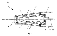
第1実施形態において、図1に示すように円錐ねじ圧縮機20は、内側要素1及び外側要素2を有する。内側要素1の外面は、実質的には第1の切頭円錐形状である。内側要素の外面4は複数の螺旋歯を有する。
In the first embodiment, as shown in FIG. 1, the
外側要素2の内面3は、実質的には、第2の切頭円錐形状である。外側要素2の内面3は、複数の螺旋歯を有し、内側要素1の螺旋歯の数より多いものとする。内側要素1及び外側要素上の各螺旋歯は、一定のピッチの螺旋を備える(円錐体の広端部から狭端部までピッチ角度を減らす)。
The inner surface 3 of the
内側要素1及び外側要素2の形状は、参照としてここに組み込むPCT外国語特許出願公開第GB2013/051497号に基づいて、例えば設計又は製造工程の一環として確定することができる。
The shape of the inner element 1 and the
内側要素1及び外側要素2は、圧縮機20の筐体6内に配置する。内側要素1及び外側要素2の両方は、筐体6内で回転可能とする。
The inner element 1 and the
内側要素1は、外歯を有する第1歯車8(ピニオンと呼ぶこともできる)に接合する。外側要素2は、内歯を有する第2歯車9に接合する。第2歯車9の内歯は、第1歯車8の外歯と噛み合う。第1歯車8の第2歯車9に対するギヤ比は、内側要素1の歯の数の外側要素2の歯の数の比と等しい。
The inner element 1 is joined to a first gear 8 (also called a pinion) having external teeth. The
図2は、第2歯車9の内側にある第1歯車8の端部図(断面図)を示す。 FIG. 2 shows an end view (cross-sectional view) of the first gear 8 inside the second gear 9.
第1歯車8は、電気モーター14のシャフトに接合する(電気モーター14は図1においては図示していない)。電気モーター14のシャフトは、内側要素1の軸に沿って並び、第1歯車8の軸と同じ軸である。 The first gear 8 is joined to the shaft of the electric motor 14 (the electric motor 14 is not shown in FIG. 1). The shaft of the electric motor 14 is aligned along the axis of the inner element 1 and is the same axis as the axis of the first gear 8.
電気モーター14のシャフトは内側要素1を駆動する。電気モーター14のシャフトは、内側要素1に接合した第1歯車8を駆動する。次に第1歯車8は外側要素2に接合した第2歯車を駆動する。歯車8・9がそれらの軸の周りを回転し始めると、圧縮機20の内側要素1及び外側要素2を回転し始める。
The shaft of the electric motor 14 drives the inner element 1. The shaft of the electric motor 14 drives the first gear 8 joined to the inner element 1. The first gear 8 then drives the second gear joined to the
内側要素1はその縦軸の周りを回転し、それを第1軸と呼び、また、外側要素2はその縦軸の周りを回転し、それを第2軸と呼ぶものとする。第1軸及び第2軸は、互いに傾斜し(並行でなく)、軸間の角度を有する。図1の実施形態において、第1軸は、1°の角度の間の角度で第2軸と交差する。
The inner element 1 rotates around its longitudinal axis and is referred to as the first axis, and the
要素の回転時に、内側要素1の螺旋歯は、外側要素の螺旋歯と結合し、内側要素1及び外側要素2間の線形の接触を形成する。線形の接触は、内側要素1及び外側要素2間のほぼ密封された螺旋状のチャンバー5を形成する。
During the rotation of the element, the helical teeth of the inner element 1 combine with the helical teeth of the outer element and form a linear contact between the inner element 1 and the
回転時、圧縮性流体(例えば、ガス状流体)は、吸引ポート11を通して内側要素1及び外側要素2の間のチャンバー5内に吸引する。本発明の実施形態において、吸引ポート11は、円錐体の大端部で外側要素の端部に隣接するように設置する。代替の実施形態において、吸引ポート11は、大端部に近いいずれかの場所に設置し、例えば、使用しやすくするいずれかの場所に設置する。
During rotation, compressible fluid (eg, gaseous fluid) is sucked into the
内側要素1及び外側要素2がそれぞれ円錐形を有し、ねじ溝が螺旋であるため、内側要素1及び外側要素2が回転すると、チャンバー5が圧縮機20の縦軸に沿って動き、体積を減らす。チャンバー5の体積の減少は、圧縮性流体を圧縮する。圧縮性流体は、圧力が上がる。
Since the inner element 1 and the
チャンバー5が圧縮機20の狭端部に到達すると、圧縮性流体は、出口12を通して排出される。高圧シールは、出口12で使用する。本発明の実施形態において、高圧シールは、金属面シールとする。他の実施形態において、いずれかの適切な高圧シールを使用する。高圧シールは、片側で高速回転(例えば、1500rpm)及び高圧で対応することができる。
When the
図1の円錐ねじ圧縮機20の操作の間、内側要素1の回転軸及び外側要素2の回転軸はそれぞれ固定されて安定した位置に留まり、要素はそれぞれの軸の周りを回転する。要素1及び2のいずれも偏心回転運動を行わない。
During operation of the
内側要素及び外側要素は、それぞれ他の要素ではなくモーターによって駆動する。従って、外側要素上の内側要素によって、若しくはその逆に及ぼされた力は、減少又は除去される。 The inner and outer elements are each driven by a motor rather than the other elements. Thus, the force exerted by the inner element on the outer element or vice versa is reduced or eliminated.
軸の正確な配置は、圧縮機20の筐体6の正確な設計及び製造により達成する。シャフトは、円錐の両側にあるカバーを有する筐体6の一部に設置する。
Accurate placement of the shaft is achieved by precise design and manufacture of the housing 6 of the
図1の実施形態において、圧縮機20の長さは189mmであり、圧縮機の垂直の大きさは95mm×95mmである。要素上の許容誤差は10マイクロメートルである。
In the embodiment of FIG. 1, the length of the
図1の実施形態において、外側要素2は合金鋼から成り、内側要素2は黄銅から成る。図1の実施形態において、黄銅を1つの要素に使用し、合金鋼をもう一方に使用する。これは、黄銅が合金鋼より柔らかいからである。いずれかの製造の誤りが存在すると、黄銅は合金鋼よりも変形又は磨耗があり、その結果、内側要素1及び外側要素2の間の固定が改良される。
In the embodiment of FIG. 1, the
図1の実施形態では、内側要素1及び外側要素2の運動を潤滑し、かつコンプレッサ内の温度を低下させるために潤滑油が使用される。内側要素1及び外側要素2間の良好な嵌合により、代替的な設計のコンプレッサ、例えば一方の要素が他方の要素を駆動ずる形式のコンプレッサで必要とされるよりも少量のオイルで十分な構成とすることができる。
In the embodiment of FIG. 1, lubricating oil is used to lubricate the movement of the inner element 1 and
円錐ねじ圧縮機の代替の実施形態を図3において示す。図3の実施形態は、円錐ねじ要素1、2の同期を図1の実施形態の代替で実施する必要がある。図3の実施形態において、外歯を備える歯車の身を円錐ねじ要素1、2の同期において使用する。
An alternative embodiment of a conical screw compressor is shown in FIG. The embodiment of FIG. 3 requires that the
図3の実施形態の内側要素1及び外側要素2は、図1の実施形態の内側要素1及び外側要素2と同様に構成され、かつ作動するように配置されている。
The inner element 1 and the
図1の実施形態において、モーター14は、内側要素1と共通の軸を共有し、シャフトによって内側要素1に接続する。逆に、図3の実施形態において、いずれの要素もシャフトによってモーター14に直接接続しない。両方の要素は同期され、歯車13、16及び17の動きによって同時に駆動する。図3の実施形態において、歯車は互いに噛み合う外歯を有し、モーターシャフト18によって駆動する。歯車16はシャフト18によって駆動し、外側要素2を駆動する。歯車17はモーターシャフト16によって駆動し、内側要素1を駆動する歯車13を駆動する。
In the embodiment of FIG. 1, the motor 14 shares a common axis with the inner element 1 and is connected to the inner element 1 by a shaft. Conversely, in the embodiment of FIG. 3, no element is directly connected to the motor 14 by the shaft. Both elements are synchronized and are driven simultaneously by the movement of
代替の実施形態において、適切な歯車機構を使用して、内側要素1及び外側要素2を同時に駆動する。
In an alternative embodiment, a suitable gear mechanism is used to drive the inner element 1 and the
図3の実施形態において、内側要素1及び外側要素2は、内側要素1及び外側要素2の回転速度比がそれらの要素のねじ表面の歯の比と同じとなるように同期する。図3の実施形態において、内側要素1及び外側要素2は圧縮機筐体6内の軸受部15に取り付ける。
In the embodiment of FIG. 3, the inner element 1 and the
図3の実施形態において、モーター14は代替の電流モーターとする。大体の実施形態において、モーター14は、直流モーター、水力モーター、内燃機関エンジン、又は内側要素1及び外側要素2の回転を駆動するいずれかの適切な方法とする。他の実施形態において、モーターを備えない駆動手段は、内側要素1及び外側要素2の回転を駆動するのに使用する。
In the embodiment of FIG. 3, motor 14 is an alternative current motor. In most embodiments, the motor 14 is a direct current motor, a hydraulic motor, an internal combustion engine, or any suitable method for driving the rotation of the inner element 1 and the
いくつかの実施形態において、第1モーターは内側要素1を回転するのに使用し、第2モーターは外側要素2を回転するのに使用する。第1モーターは、例えばシャフトによって内側要素1に直接接続する、又は、例えば歯車を使用して内側要素1に間接的に接続する。第2モーターは、例えばシャフトによって外側要素2に直接接続する、又は、例えば歯車を使用して外側要素2に間接的に接続する。第1及び第2モーターは、制御器によって制御し、内側要素1の回転が外側要素2の回転と同期するようにする。
In some embodiments, the first motor is used to rotate the inner element 1 and the second motor is used to rotate the
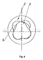
螺旋ねじ溝の特定の配置を図1及び図3において示したが、代替の実施形態において、いずれかの適切な数又は配置のねじ溝を使用することができる。図4は、3つの螺旋ねじ溝を有する内側要素1及び4つの螺旋ねじ溝を有する外側要素2の断面図を示す。図4はまた、内側要素1及び外側要素2の間のチャンバー5を示す。図5は、内側要素1及び外側要素2の代替の設計を示す。異なる実施形態において、異なる数の螺旋ねじ溝を使用する。
Although a particular arrangement of spiral threads is shown in FIGS. 1 and 3, in alternate embodiments, any suitable number or arrangement of threads can be used. FIG. 4 shows a cross-sectional view of the inner element 1 with three helical threads and the
図1の実施形態において、螺旋ねじ溝は一定のピッチ(変化するピッチ角度)を有する。他の実施形態において、螺旋ねじ溝は変化するピッチを有し、例えば連続的に変化するピッチを有する。いくつかの実施形態において、螺旋ねじ溝は変化するピッチを有し、ピッチ角度は内側又は外側要素1、2の長さに沿って一定を保持できる。
In the embodiment of FIG. 1, the spiral thread groove has a constant pitch (a changing pitch angle). In other embodiments, the helical thread has a varying pitch, eg, has a continuously varying pitch. In some embodiments, the helical thread has a varying pitch and the pitch angle can remain constant along the length of the inner or
上述の実施形態において、各螺旋ねじ溝は、内側又は外側要素1、2の全長に沿って延在する。代替の実施形態において、各螺旋ねじ溝は、内側又は外側要素1、2の長さの少なくとも一部に沿って延在する。
In the embodiment described above, each helical thread extends along the entire length of the inner or
図1の圧縮機2は、長さが189mmのプロトタイプとして製造した。代替の実施形態において、圧縮機2は、様々な大きさに製造できるものとする。例えば、圧縮機の長さは、10mmから5mの範囲であるとする。小さい圧縮機、例えば、10mmから100mmの圧縮機は、特定の装置として使用でき、例えば、空調機において使用する。大きな圧縮機、例えば、0.5〜2m又はそれより長い圧縮機は、例えば石油ガス装置において使用できる。
The
外側要素2上の内側要素1によって(又はその逆)及ぼされた力の要素を同時に駆動することによる除去又は減少は、大きな圧縮機の場合において特にインパクトがある。 The removal or reduction by simultaneously driving the elements of the force exerted by the inner element 1 on the outer element 2 (or vice versa) is particularly impactful in the case of large compressors.
小さい圧縮機は、圧縮機を組み立てるのに使用する材料の特性と比較して大きなトルクを持たない。しかし、大きな圧縮機(例えば、1メートル長さの圧縮機)において、要素は大きな質量を有する。従って、大きなトルクを持つ。内側要素1及び外側要素2の間の接触範囲は、線形のみであり、そのため、小さい接触範囲となる。1つの要素が他の要素を駆動すると、その結果できた履歴現象及び磨耗は大きくなる。1つの要素が他の要素を駆動すると、大きな圧縮機は、小さな圧縮機によって経験するよりも大きな磨耗を経験する。したがって、要素の同期は、小さな圧縮機において見られるよりも大きな圧縮機の方が大きく磨耗を減少させることができる。
A small compressor does not have a large torque compared to the properties of the material used to assemble the compressor. However, in a large compressor (eg, a 1 meter long compressor), the element has a large mass. Therefore, it has a large torque. The contact range between the inner element 1 and the
更なる実施形態において、例えば塗工層等の外装は、内側要素1の外面4の少なくとも一部及び/又は外側要素2の内面3の少なくとも一部に塗布する。この塗工は、摩擦力を減らし、及び/又は腐食抵抗を増加させる。1つの実施形態において、塗工材料はテフロンとする。他の実施形態において、塗工材料はいずれかの摩擦を減少させる材料である。更なる実施形態において、塗工層はいずれかの腐食抵抗性材料である。いくつかの実施形態において、1つ又は両方の要素は、本体の表面の一部又は全体を覆う外装を備えた本体を有する。いくつかの実施形態において、本体は、硬質の材料、例えば金属であり、外層は柔らかい材料、例えばプラスチックである。
In a further embodiment, an exterior, for example a coating layer, is applied to at least part of the outer surface 4 of the inner element 1 and / or at least part of the inner surface 3 of the
図1の実施形態において、1つの要素は合金鋼から形成し、もう一方の要素は黄銅から形成する。代替の実施形態において、内側要素1及び外側要素2のそれぞれは、産業プラスチックであるポリアミド-6(ウルトラアミドという商品名でBASFによって売られている)から組み立てる。ポリアミド-6等のプラスチック材料から作成した要素は、腐食性ガスに使用するのに適している。プラスチックは、接触内外で変形してその形を修復し、要素を硬質の材料、例えば金属材料から作成した時よりも、プラスチックで作成した時に、要素間の接触をより硬くすることができる。
In the embodiment of FIG. 1, one element is formed from alloy steel and the other element is formed from brass. In an alternative embodiment, each of the inner element 1 and
図1の実施形態において、オイルを潤滑させるために使用する。他の実施形態において、オイルはまた冷却のために使用する。1つ又はそれ以上の要素が軟質の材料、例えばプラスチック材料から成る実施形態において、潤滑のためオイルの使用は減少又は除去される。 In the embodiment of FIG. 1, it is used to lubricate oil. In other embodiments, the oil is also used for cooling. In embodiments where the one or more elements are made of a soft material, such as a plastic material, the use of oil for lubrication is reduced or eliminated.
モーター14を使用して内側要素1及び外側要素2を同時に駆動すると、要素上の磨耗を減少させることができ、また、より正確な誤差及びより良い要素間の接触となる。要素間の接合が改良されると、使用するのに必要なオイルは少なくなる。
Using the motor 14 to drive the inner element 1 and the
いくつかの実施形態において、要素の軸を正確に設置することで、要素上の磨耗を減少させることができる。いくつかの実施形態において、軸を正確に設置することで、厳密に配置した要素間の隙間ができる。このような1つの実施形態において、圧縮機20は、小さな固体粒子、例えばダストまたは砂を含むガス状流体を圧縮するように設計する。要素間の隙間は、粒子の大きさを考慮して厳密に配置することができる。隙間を厳密に配置すると、圧縮機の寿命を長くすることができる。
In some embodiments, precise placement of the element axis can reduce wear on the element. In some embodiments, precise placement of the shaft creates a gap between closely positioned elements. In one such embodiment, the
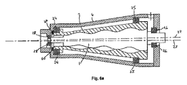
更なる実施形態の円錐ねじ圧縮機は、図6a、6b及び6cにおいて図示する(図6b及び6cは図6aの部品の詳細図である)。 A further embodiment of the conical screw compressor is illustrated in FIGS. 6a, 6b and 6c (FIGS. 6b and 6c are detailed views of the components of FIG. 6a).
図6aの円錐ねじ圧縮機20は、図1を参照して説明した螺旋歯及びねじ溝を備える内側要素1並びに外側要素2を有する。内側要素1は固体要素である(しかし、図6a〜6cにおいてははっきりとしないように示している)。
The
内側要素1は、モーター14(図6aにおいては示さない)によって駆動するシャフト21に接合する。操作において、モーター14は(シャフト21を介して)内側要素1を駆動し、その縦軸(第1軸22)の周りを回転させる。内側要素1の回転は、外側要素2を外側要素自身の縦軸(第2軸23)の周りの回転を駆動し、外側要素の縦軸は内側要素2の縦軸22に対して傾斜している。
The inner element 1 is joined to a shaft 21 driven by a motor 14 (not shown in FIG. 6a). In operation, the motor 14 drives the inner element 1 (via the shaft 21) and rotates around its longitudinal axis (first axis 22). The rotation of the inner element 1 drives the
内側要素1は、回転軸22に沿って縦軸位置においてほぼ固定する。外側要素2は、回転軸23に沿って縦軸位置においてほぼ固定する。軸22、23は、ともに固定された位置となる。外側要素2及び内側要素1の相対的な縦軸位置はほぼ維持される、これは、内側要素1及び外側要素2が相対的に固定された位置に保持されて、外側要素2の内面3及び内側要素1の外面4を硬く取り付け、ガスを内側要素1及び外側要素2の間の密室5において維持することができるからである。
The inner element 1 is substantially fixed at the longitudinal axis position along the
内側要素1及び外側要素2は、軸受部、例えば軸受部28によって相対的に縦軸位置で設置する。軸受部28は、内側要素1の端面34と接触する。
The inner element 1 and the
図6aの実施形態において、筐体6の上端は内側要素1の上部に並んでいる内面36を備える陥没を有する。内側要素1の端面34は、外側要素2の内面36に面する。軸受部28は、筐体6の陥没した内面36及び内側要素1の端面の間に配置する。
In the embodiment of FIG. 6 a, the upper end of the housing 6 has a depression with an
いくつかの実施形態において、内側要素1の上端部にステップを付け、端面ステップ表面34は筐体6の内面36に面する。
In some embodiments, the upper end of the inner element 1 is stepped and the
いくつかの実施形態において、外側要素2の上端部は、内側要素の上端部に並ぶ内面を持つ陥没を有する。軸受部28は、外側要素1の陥没した内面及び内側要素1の端面、例えば、内側要素1の端面するステップ表面の間に配置する。
In some embodiments, the upper end of the
本発明の実施形態において、軸受部28は端面ステップ表面34と接触するが。他の実施形態において、軸受部28は、いずれかの内側要素1の端面及び外側要素2のいずれかの適切に面する表面に接触する。
In the embodiment of the present invention, the bearing
更なる実施形態において、軸受部は、内側要素1のいずれかの端面及び筐体6のいずれかの適切に面する表面に接触する。 In a further embodiment, the bearing part contacts either end face of the inner element 1 and any appropriately facing surface of the housing 6.
内側要素1は、筐体において、軸受部、例えば放射状の軸受部26によって、シャフト21及び筐体6の間に固定する。図6の実施形態において、シャフト21は、圧縮機の下端部を覆う筐体6の部分に面する表面27を有するステップを持つ。筐体6のこのカバー部分は、対応するノッチ29を有し、縦軸方向に、放射状の軸受部26をステップ表面27及びノッチ29の間に配置できるようにする。
The inner element 1 is fixed between the shaft 21 and the housing 6 by a bearing portion, for example, a
内側要素1は軸受部26によって筐体6に固定し、内側要素1の動きがその縦軸22の周りを回転するように限定する。内側要素1及び筐体6の間に軸受部26を配置すると、
内側要素1は外側要素2に対してその軸22に沿って動くことができず、それによって、内側要素1及び外側要素2の間の隙間を通してガス漏れの可能性を限定する。
The inner element 1 is fixed to the housing 6 by a bearing
The inner element 1 cannot move along its
外側要素2は、外側要素の縦軸22にほぼ垂直に延びる、対応するフランジ40を有する。フランジ40は筐体の内面38に面する。
The
軸受部24は、外側要素2及び筐体6の間に放射方向に配置する。軸受部24は、筐体の内面38及びフランジ表面40の間に放射方向に配置し、それによって、外側要素2の縦軸位置を筐体6に対して固定する。軸受部24は、外側要素2及び筐体6の相対的な動きを外側要素2のその縦軸23の周りの回転に限定する放射状の軸受部である。
The bearing
他の要素において、軸受部24は、筐体のいずれかの内面及び外側要素2のいずれかの適切な表面の間に縦軸位置に配置する。高圧シール60は、外側要素2の端部及び筐体6に配置する。
In other elements, the
更なる軸受部、例えば更なる放射状軸受部25は、外側要素2及び外側要素2の下端部に接近した筐体6の間に設置する。軸受部25の縦軸位置は、縦軸23に垂直な表面及び外側要素2において対応し、面するリップを有する筐体6におけるリップによって画定する。
A further bearing part, for example a further
外側要素2は、2つの軸受部24、25によって安定した筐体6において固定し、外側要素2の動きがその縦軸23に沿った回転に限定する。
The
軸受部24、25を外側要素2及び筐体6の間に配置すると、外側要素2は内側要素1に対するその軸に沿って動くことができなくなり、内側要素1及び外側要素2の間の隙間を通したガス漏れの可能性を限定する。
If the
他の実施形態において、外側要素2は、2つ又はそれ以上の軸受部のいずれかの配置によって固定し、外側要素2の長さに沿っていずれかの適切な位置に設置する。
In other embodiments, the
内側要素1及び外側要素2は各自の固定軸の周りをそれぞれ回転する。内側要素1は、軸受部26によって筐体6において固定するため、内側要素1はその軸22の周りの回転以外の他の動きをしない。したがって、システムにおけるエネルギーの大部分は、気体を圧縮するのに使用する。内側要素1の偏心振動等の他の動きを回避することによって、このシステムはより効率的に作成され、エネルギーの消耗を減少させる。
The inner element 1 and the
内側要素1を外側要素2の内部に軸受部26を用いて固定すると、内側要素1及び外側要素2の相対的な位置を正確に設定することができる。その結果、誤差が減少する。内側要素1及び外側要素2の相対的な位置を正確に設置することにより、不必要な力の使用は回避でき、内側要素1及び外側要素2の表面の間の不必要な摩擦を避けることもできる。
When the inner element 1 is fixed to the inside of the
内側要素1は、2つの側面上の軸受部によって保持され、外側要素2は2つの側面上の軸受部によって保持される。軸受部によって保持されている要素によって、内側要素1の位置及び外側要素2の位置2を互いに対して、また筐体に対して正確に設置することができる。この配置は、内側要素1及び外側要素2を鋼鉄等の硬質の材料から製造するときに、特に効率的である。
The inner element 1 is held by bearings on two sides and the
更なる実施形態を図7において示す。 A further embodiment is shown in FIG.
図7の実施形態は、図6に類似した、内側要素1、外側要素2、及び筐体6を有する。外側要素2は2つの軸受部24、25によって固定する。
The embodiment of FIG. 7 has an inner element 1, an
内側要素は、下端部で1つの軸受部26によって固定する。内側要素1の上端部は、外側要素2の表面によって内側要素1及び外側要素2間の接触ラインにおいて固定する。
The inner element is fixed by one bearing
その位置における内側要素1は、接触ラインに沿って外側要素2の表面を押し、それによって、要素間のより良いシーリングを形成し、密室5を分け、また、チャンバーにおける圧縮性流体が漏れることを防ぐ。図7における配置は、内側要素1を1つの軸受部26によって保持し、少なくとも1つの内側要素1及び外側要素2をポリマー等の軟質の材料から作成した時に、特に効率的である。
The inner element 1 in that position pushes the surface of the
圧縮機20は、さらに、外側要素2の端部及び筐体6の間に配置した高圧シールと、圧縮された流体を除去するための圧縮機の排出口(図示せず)にパイプ又は他の導管のコネクタとを有する。
The
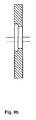
図7の実施形態において、筐体6は、カバー32を有し、圧縮機の下端部を覆う。
In the embodiment of FIG. 7, the housing 6 has a
カバー32は、固定した方法で、2つの要素の相対的に傾いた軸22、23を保持するように配置する。カバーは2つの軸を有し:a)外側要素2の第2軸23と同じ縦軸位置上に設置した主軸と、b)第2軸に対して傾いている第1軸22(内側要素1の軸)の結果できたオフセットを有する内側要素1にたいする軸受部26をマウントする場所とを有する。図8a及び8bにおいて、相対的な傾斜の結果できたオフセットは、明瞭にするため誇張している。
The
更なる実施形態において、筐体6は圧縮機の下端部を覆う筐体カバーを有する。筐体カバーに軸受部カバーは付着する。 In a further embodiment, the housing 6 has a housing cover that covers the lower end of the compressor. The bearing cover adheres to the housing cover.
軸受部カバーは、放射状の軸受部26の下端部を覆うプレートと、放射状の軸受部26を囲む円柱部分とを有する。放射状の軸受部26は、シャフト21及び軸受部カバーの円柱部分の内面の間に配置する。
The bearing portion cover includes a plate that covers the lower end portion of the
筐体カバー及び軸受部カバーは、内側要素1のシャフト21を外側要素2の軸に対して適切な角度で傾斜するように保持するように設計する。筐体カバー及び軸受部カバーは、取り外し可能なユニットを形成する。
The housing cover and the bearing cover are designed to hold the shaft 21 of the inner element 1 so as to be inclined at an appropriate angle with respect to the axis of the
圧縮性流体は、ノズルを通して圧縮機内に注入する。 The compressible fluid is injected into the compressor through a nozzle.
外側要素2の下端部は、外側要素カバーによって覆う。外側要素カバーは、縦軸を有する広い環状構造であり、軸受部25を、外側要素カバーの放射状の外面及び筐体カバーの放射状のない表面の間に放射状に設置できるようにする。
The lower end portion of the
圧縮機の上端部で、外側要素2は内側要素1の端部の下に広がる管状領域を形成して広がる。フランジ40は、末端部に付ける。放射状の軸受部24は、末端部及び筐体6の一部の間に設置する。
At the upper end of the compressor, the
図6及び図7の実施形態において、各軸受部は、1つのボール軸受部又は複数のボール軸受部を有する。他の実施形態において、いずれかの適切な型の軸受部を使用することができる。 In the embodiment of FIGS. 6 and 7, each bearing portion has one ball bearing portion or a plurality of ball bearing portions. In other embodiments, any suitable type of bearing can be used.
いくつかの実施形態において、圧縮機は、内側要素1及び外側要素2の相対的な縦軸位置を調整する方法を有する。
In some embodiments, the compressor has a method of adjusting the relative longitudinal position of the inner element 1 and the
内側要素1及び外側要素2の相対的な縦軸位置を調整することによって、外側要素2の内面3及び内側要素1の外面4の間の固定をより硬く、又は硬くしないようにできる。要素間の隙間は、要素の相対的な縦軸位置を調整することによって調整できる。要素の相対的な縦軸位置を調整することは、圧縮機20における圧力を大きく変えることとなり、従って、捜査における圧縮機によって生成する熱を大きく狩ることができることがわかる。
By adjusting the relative longitudinal position of the inner element 1 and the
いくつかの実施形態において、内側要素1及び外側要素2の相対的な縦軸位置は、軸受部24、25、26及び26の縦軸位置を調整することによって調整する。
In some embodiments, the relative longitudinal position of the inner element 1 and the
要素の相対的な縦軸位置を硬く固定するために調整することによって、チャンバーはよく密閉され高圧となることができる。しかし、固定がより硬くなると、機会損失によりトルクが増加する。システムの温度は圧力によって高くなる。 By adjusting the relative longitudinal position of the elements to be rigidly fixed, the chamber can be well sealed and at high pressure. However, as the fixation becomes harder, torque increases due to opportunity loss. The temperature of the system increases with pressure.
したがって、外側要素2及び内側要素1の相対的な縦軸位置を特定の装置に対して厳密に制御することが大切であり、達成する圧力及び生成する熱の均衡を取ることも大切である。
It is therefore important to strictly control the relative longitudinal position of the
更なる実施形態において、圧縮機は、内側要素1の縦軸位置をその回転軸22に沿ってほぼ固定するいずれかの手段と、外側要素3の縦軸位置をその回転軸23に沿ってほぼ固定するいずれかの手段を有し、内側要素及び外側要素の相対的な縦軸位置を回転の間ほぼ維持することができる。
In a further embodiment, the compressor has any means for substantially fixing the longitudinal position of the inner element 1 along its
いくつかの実施形態において、内側要素1及び外側要素2の縦軸位置をほぼ固定する手段は、少なくとも1つの歯車を備える軸受部装置を有する。
In some embodiments, the means for substantially fixing the longitudinal position of the inner element 1 and the
例えば、一つの実施形態において、内側要素1は第1歯車8によって駆動する。第1歯車は、駆動モーター14のシャフトに結合する。逆に第1歯車8は、外側要素9に結合する第2歯車9を駆動する。外側要素2は、筐体6において2つの軸受部24、25によって外側要素2の各端部に固定する。圧縮機はさらに、外側要素2及び内側要素1の間に軸受部26を有する。したがって、この実施形態において、内側要素1及び外側要素2の相対的な縦軸位置は、歯車及び軸受部の組み合わせによってほぼ維持することができる。
For example, in one embodiment, the inner element 1 is driven by the first gear 8. The first gear is coupled to the shaft of the drive motor 14. Conversely, the first gear 8 drives the second gear 9 that is coupled to the outer element 9. The
第1歯車8及び第2歯車9は、図1を参考にして上述した通りである。他の実施形態において、内側要素1及び外側要素2は、図3を参考にして上述した通り歯車13、16、17の配置によって駆動する。更なる実施形態において、いずれかの適切な歯車配置を使用する。
The first gear 8 and the second gear 9 are as described above with reference to FIG. In another embodiment, the inner element 1 and the
ここで説明する異なる実施形態の要素は、いずれかの適切な方法において結合する。例えば、1つの実施形態における圧縮機は、1つ又はそれ以上の歯車を有し、例えば、図1又は図3において示し、また、1つまたはそれ以上の軸受部を有し、例えば、図6a又は図7aにおいて示したような軸受部28がある。筐体6及びカバー30、31、32は、図7aを参照して説明しているが、図1又は図3の実施形態に適用できる。
The elements of the different embodiments described herein are combined in any suitable manner. For example, the compressor in one embodiment has one or more gears, for example as shown in FIG. 1 or FIG. 3 and has one or more bearings, for example FIG. 6a. Or there is a
説明した実施形態の円錐ねじ圧縮機は、ポンプとして操作できることを理解されたい。 It should be understood that the conical screw compressor of the described embodiment can be operated as a pump.
上述の実施形態の円錐ねじ圧縮機又はポンプは、多くの産業をまたがって様々な装置に使用することができ、例えば、石油ガス海上プラットフォーム、海上炭素の回収及び蓄積、採掘、船、並びに宇宙船がある。 The conical screw compressor or pump of the above-described embodiments can be used in a variety of devices across many industries, such as oil and gas offshore platforms, offshore carbon capture and storage, mining, ships, and spacecraft. There is.
本発明は、実施例を使用して単に説明し、詳細の修正は本発明の範囲において可能であることを理解されたい。 It will be understood that the present invention has been described by way of example only and modifications of detail are possible within the scope of the invention.
各特性は、明細書及び(適切な)請求項及び図面において開示し、個々に又はいずれかの適切な組合せにおいて提供することができる。 Each feature is disclosed in the description and (where appropriate) the claims and drawings, and may be provided individually or in any appropriate combination.
Claims (46)
第1軸の周りを回転するように構成した内側要素と、
第2軸の周りを回転するように構成した外側要素を備え、
内側要素の外面及び外側要素の内面は、回転時に互いに噛み合って同時に動作するねじ溝及び歯を有し、
第1軸及び第2軸はそれぞれ固定し、第1軸は第2軸に対して傾斜し、
内側要素及び外側要素は、操作に際して同時回転することにより、内側要素が外側要素に及ぼす力、又は外側要素が内側要素に及ぼす力を減少又は除去するように構成した、円錐ねじ圧縮機又はポンプ。 A conical screw compressor or pump,
An inner element configured to rotate about a first axis;
Comprising an outer element configured to rotate about a second axis;
The outer surface of the inner element and the inner surface of the outer element have thread grooves and teeth that engage with each other during rotation and operate simultaneously,
The first axis and the second axis are fixed, the first axis is inclined with respect to the second axis,
A conical screw compressor or pump configured to reduce or eliminate the force exerted by the inner element on the outer element or the force exerted on the inner element by rotating the inner element and the outer element simultaneously during operation.
a)内側要素の外面の少なくとも一部を、外側要素の内面の少なくとも一部を形成する材料よりも硬質の材料から形成し、又は
b)外側要素の内面の少なくとも一部を、内側要素の外面の少なくとも一部を形成する材料よりも硬質の材料から形成する、圧縮機又はポンプ。 In the conical screw compressor or pump according to any one of claims 1 to 10,
a) forming at least part of the outer surface of the inner element from a material harder than the material forming at least part of the inner surface of the outer element, or b) forming at least part of the inner surface of the outer element on the outer surface of the inner element A compressor or pump formed from a material that is harder than the material that forms at least a portion thereof.
第2軸の周りを回転するように構成した外側要素を備え、
内側要素の外面及び外側要素の内面は、回転時に互いに噛み合って同時に動作するねじ溝及び歯を有し、
第1軸及び第2軸はそれぞれ固定し、第1軸は第2軸に対して傾斜した円錐ねじ圧縮機又はポンプを操作する方法であって、この方法は、
内側要素及び外側要素を同時に回転させることによって、内側要素が外側要素に及ぼす力、又は外側要素が内側要素に及ぼす力を減少又は除去するステップを備える、方法。 An inner element configured to rotate about a first axis;
Comprising an outer element configured to rotate about a second axis;
The outer surface of the inner element and the inner surface of the outer element have thread grooves and teeth that engage with each other during rotation and operate simultaneously,
A method of operating a conical screw compressor or pump, wherein the first axis and the second axis are fixed and the first axis is inclined with respect to the second axis, the method comprising:
A method comprising reducing or eliminating a force exerted by an inner element on an outer element or a force exerted by an outer element on an inner element by simultaneously rotating the inner element and the outer element.
第1軸の周りを回転するように構成した内側要素と、
第2軸の周りを回転するように構成した外側要素と、
内側要素の縦軸方向の位置を第1軸に沿ってほぼ固定すると共に、外側要素の縦軸方向の位置を第2軸に沿ってほぼ固定する固定手段とを備え、該固定手段によって、回転の間、内側要素及び外側要素の相対的な縦軸方向の位置をほぼ維持することができ、
内側要素の外面及び外側要素の内面は、回転時に噛み合って同時に動作するねじ溝及び歯を有し、
第1軸及び第2軸はそれぞれ固定し、第1軸は第2軸に対して傾斜している、圧縮機又はポンプ。 A conical screw compressor or pump,
An inner element configured to rotate about a first axis;
An outer element configured to rotate about a second axis;
A fixing means for substantially fixing the position of the inner element in the longitudinal direction along the first axis, and for fixing the position of the outer element in the longitudinal direction along the second axis. During which the relative longitudinal position of the inner and outer elements can be substantially maintained,
The outer surface of the inner element and the inner surface of the outer element have thread grooves and teeth that engage and operate simultaneously during rotation,
A compressor or pump in which the first axis and the second axis are fixed, and the first axis is inclined with respect to the second axis.
a)内側要素は、駆動手段によって駆動するように構成すると共に、外側要素は内側要素によって駆動するように構成し、または
b)外側要素は、駆動手段によって駆動するように構成すると共に、内側要素は外側要素によって駆動するように構成した、
圧縮機又はポンプ。 A conical screw compressor or pump according to claim 38, wherein either a) or b) below:
a) the inner element is configured to be driven by the driving means and the outer element is configured to be driven by the inner element, or b) the outer element is configured to be driven by the driving means and the inner element Configured to be driven by the outer element,
Compressor or pump.
第2軸の周りを回転するように構成した外側要素を備え、
内側要素の外面及び外側要素の内面は、回転時に噛み合って同時に動作するねじ溝及び歯を有し、
第1軸及び第2軸はそれぞれ固定し、第1軸は第2軸に対して傾斜した円錐ねじ圧縮機又はポンプを操作する方法であって、この方法は、
内側要素の縦軸位置を第1軸に沿ってほぼ固定すると共に外側要素の縦軸位置を第2軸に沿ってほぼ固定することにより、回転の間内側要素及び外側要素の相対的な縦軸位置をほぼ維持可能とするステップと、
内側要素及び外側要素を回転させるステップと、
を備える、方法。 An inner element configured to rotate about a first axis;
Comprising an outer element configured to rotate about a second axis;
The outer surface of the inner element and the inner surface of the outer element have thread grooves and teeth that engage and operate simultaneously during rotation,
A method of operating a conical screw compressor or pump, wherein the first axis and the second axis are fixed and the first axis is inclined with respect to the second axis, the method comprising:
By substantially fixing the longitudinal position of the inner element along the first axis and substantially securing the longitudinal position of the outer element along the second axis, the relative longitudinal axes of the inner element and the outer element during rotation. A step that allows the position to be substantially maintained;
Rotating the inner and outer elements;
A method comprising:
Applications Claiming Priority (5)
| Application Number | Priority Date | Filing Date | Title |
|---|---|---|---|
| GB1402886.4 | 2014-02-18 | ||
| GB201402886A GB201402886D0 (en) | 2014-02-18 | 2014-02-18 | Rotary positive-displacement machine |
| GB1413716.0 | 2014-08-01 | ||
| GB201413716A GB201413716D0 (en) | 2014-08-01 | 2014-08-01 | Rotary positive-displacement machine |
| PCT/GB2015/050459 WO2015124918A1 (en) | 2014-02-18 | 2015-02-18 | Rotary positive-displacement machine |
Publications (1)
| Publication Number | Publication Date |
|---|---|
| JP2017506308A true JP2017506308A (en) | 2017-03-02 |
Family
ID=52597012
Family Applications (1)
| Application Number | Title | Priority Date | Filing Date |
|---|---|---|---|
| JP2016553361A Pending JP2017506308A (en) | 2014-02-18 | 2015-02-18 | Positive displacement rotary machine |
Country Status (8)
| Country | Link |
|---|---|
| US (2) | US10480506B2 (en) |
| EP (2) | EP3301301A1 (en) |
| JP (1) | JP2017506308A (en) |
| CA (2) | CA3153581C (en) |
| DK (1) | DK3108142T3 (en) |
| GB (1) | GB201502738D0 (en) |
| HK (1) | HK1245373A1 (en) |
| WO (1) | WO2015124918A1 (en) |
Cited By (3)
| Publication number | Priority date | Publication date | Assignee | Title |
|---|---|---|---|---|
| KR20200055768A (en) * | 2017-09-21 | 2020-05-21 | 아틀라스 캅코 에어파워, 남로체 벤누트삽 | Cylindrical symmetrical positive displacement machine |
| JP2020525699A (en) * | 2017-06-28 | 2020-08-27 | アトラス コプコ エアーパワー, ナームローゼ フェンノートシャップATLAS COPCO AIRPOWER, naamloze vennootschap | Cylindrical symmetric positive displacement machine |
| JP2020534465A (en) * | 2017-09-21 | 2020-11-26 | アトラス コプコ エアーパワー, ナームローゼ フェンノートシャップATLAS COPCO AIRPOWER, naamloze vennootschap | Cylindrical symmetric positive displacement machine |
Families Citing this family (4)
| Publication number | Priority date | Publication date | Assignee | Title |
|---|---|---|---|---|
| JP5802914B1 (en) * | 2014-11-14 | 2015-11-04 | 兵神装備株式会社 | Fluid transfer device |
| US10174973B2 (en) | 2015-08-27 | 2019-01-08 | Vert Rotors Uk Limited | Miniature low-vibration active cooling system with conical rotary compressor |
| US9776739B2 (en) | 2015-08-27 | 2017-10-03 | Vert Rotors Uk Limited | Miniature low-vibration active cooling system with conical rotary compressor |
| DE102017100715A1 (en) * | 2017-01-16 | 2018-07-19 | Hugo Vogelsang Maschinenbau Gmbh | Control of the gap geometry in an eccentric screw pump |
Citations (4)
| Publication number | Priority date | Publication date | Assignee | Title |
|---|---|---|---|---|
| JPS54129212A (en) * | 1977-12-28 | 1979-10-06 | Orszagos Koolaj Gazipari | Multiipurpose axial flow apparatus |
| JPS63212790A (en) * | 1987-02-28 | 1988-09-05 | Toshiba Corp | Compressor |
| WO2008000505A1 (en) * | 2006-06-30 | 2008-01-03 | Grundfos Management A/S | Moineau pump |
| JP2010001876A (en) * | 2008-06-23 | 2010-01-07 | Heishin Engineering & Equipment Co Ltd | Uniaxial eccentric screw pump |
Family Cites Families (48)
| Publication number | Priority date | Publication date | Assignee | Title |
|---|---|---|---|---|
| US1892217A (en) | 1930-05-13 | 1932-12-27 | Moineau Rene Joseph Louis | Gear mechanism |
| US2085115A (en) | 1934-05-02 | 1937-06-29 | Moineau Rene Joseph Louis | Gear mechanism |
| US2615436A (en) * | 1950-11-15 | 1952-10-28 | Walter S Pawl | Planetary type engine |
| GB722965A (en) | 1952-10-27 | 1955-02-02 | Walter Stanley Pawl | Improvements in or relating to rotary engines |
| HU175810B (en) | 1977-12-28 | 1980-10-28 | Orszagos Koolaj Gazipari | Axial-flow multiple-purpose flow apparatus |
| BR8707675A (en) | 1986-04-23 | 1989-08-15 | Svenska Rotor Maskiner Ab | ROTARY POSITIVE DISPLACEMENT MACHINE OF CONICA GEAR TYPE FOR A COMPRESSIBLE WORKING FLUID |
| DE19758086A1 (en) | 1997-12-30 | 1999-07-01 | Artemis Kautschuk Kunststoff | Elastomeric stator for eccentric screw- or mono pump |
| DE19804259A1 (en) | 1998-02-04 | 1999-08-12 | Artemis Kautschuk Kunststoff | Elastomer stator for eccentric screw pumps |
| DE19804260C2 (en) | 1998-02-04 | 2003-04-10 | Artemis Kautschuk Kunststoff | Elastomer stator for an eccentric screw pump |
| US6241486B1 (en) | 1998-03-18 | 2001-06-05 | Flowserve Management Company | Compact sealless screw pump |
| DE19821867A1 (en) | 1998-05-15 | 1999-11-18 | Artemis Kautschuk Kunststoff | Downhole deep drilling motor based on eccentric mono-pump principle |
| US7186101B2 (en) | 1998-07-31 | 2007-03-06 | The Texas A&M University System | Gerotor apparatus for a quasi-isothermal Brayton cycle Engine |
| FR2794498B1 (en) | 1999-06-07 | 2001-06-29 | Inst Francais Du Petrole | PROGRESSIVE CAVITY PUMP WITH COMPOSITE STATOR AND MANUFACTURING METHOD THEREOF |
| DE19950257B4 (en) | 1999-10-18 | 2013-01-17 | Wilhelm Kächele GmbH Elastomertechnik | Eccentric screw pump with fully lined stator |
| DE19950258A1 (en) | 1999-10-18 | 2001-04-26 | Wilhelm Kaechele Gmbh Elastome | Eccentric worm pump or motor has stator with end ring with through opening of essentially similar shape to stator interior, threaded with same pitch and number of turns over ring thickness |
| DE10103476C1 (en) | 2001-01-26 | 2002-11-14 | Usd Formteiltechnik Gmbh | Slide-in stator for eccentric screw pumps |
| US6604921B1 (en) | 2002-01-24 | 2003-08-12 | Schlumberger Technology Corporation | Optimized liner thickness for positive displacement drilling motors |
| US7008200B2 (en) | 2002-02-05 | 2006-03-07 | The Texas A&M University System | Gerotor apparatus for a quasi-isothermal brayton cycle engine |
| AU2003216456A1 (en) | 2002-02-27 | 2003-09-09 | North Carolina State University | Use of electroactive monolayers in generating negative differential resistance behaviors and devices employing the same |
| US6604922B1 (en) | 2002-03-14 | 2003-08-12 | Schlumberger Technology Corporation | Optimized fiber reinforced liner material for positive displacement drilling motors |
| EP1382853B1 (en) | 2002-07-17 | 2006-02-22 | Elthom Enterprises Limited | Rotary screw machine and method of transforming a motion in such a machine |
| EP1406016A1 (en) | 2002-10-04 | 2004-04-07 | Steven M. Wood | Progressive cavity pumps using composite materials |
| WO2005005836A1 (en) | 2003-07-14 | 2005-01-20 | Elthom Enterprises Limited | Volume screw machine of rotary type |
| ES2279917T5 (en) | 2003-10-07 | 2013-06-24 | Johann Heinrich Bornemann Gmbh - Kunststofftechnik Obernkirchen - | Eccentric worm pump and stator for such a pump |
| US7192260B2 (en) | 2003-10-09 | 2007-03-20 | Lehr Precision, Inc. | Progressive cavity pump/motor stator, and apparatus and method to manufacture same by electrochemical machining |
| US7316548B2 (en) | 2003-11-17 | 2008-01-08 | Artemis Kautschuk-Und Kunststoff-Technik Gmbh | Stator for an eccentric screw pump or an eccentric worm motor operating on the Moineau principle |
| DE102004001817B4 (en) | 2004-01-08 | 2012-07-12 | Herbert Naumann | Internal-axis gear pump with variable capacity |
| CN100501134C (en) | 2004-01-14 | 2009-06-17 | 埃尔汤姆企业公司 | Energy transformation method for volumetric type rotating screw machine |
| US7517202B2 (en) | 2005-01-12 | 2009-04-14 | Smith International, Inc. | Multiple elastomer layer progressing cavity stators |
| DE502006002188D1 (en) | 2006-01-26 | 2009-01-08 | Grundfos Management As | Cavity Pump |
| EP2035709B1 (en) | 2006-06-30 | 2016-05-25 | Grundfos Management A/S | Moineau type pump |
| DE202006013966U1 (en) | 2006-09-12 | 2006-12-07 | Kletke, Axel, Dr.-Ing. | Thermal engine e.g. for Stirling, Otto or Diesel engines, has external rotor and inner rotor with rotors rotate and move around their own axis where rotors rest and rotors having teeth |
| JP2008175199A (en) | 2006-12-20 | 2008-07-31 | Heishin Engineering & Equipment Co Ltd | Uniaxial eccentric screw pump |
| ATE502214T1 (en) | 2007-05-04 | 2011-04-15 | Grundfos Management As | MOINEAU PUMP |
| NO327503B1 (en) | 2007-09-20 | 2009-07-27 | Agr Subsea As | Eccentric screw pump with multiple pump sections |
| ATE445782T1 (en) | 2007-11-02 | 2009-10-15 | Grundfos Management As | MOINEAU PUMP |
| US7854111B2 (en) | 2008-03-07 | 2010-12-21 | General Electric Company | Axial flow positive displacement turbine |
| WO2009139658A1 (en) | 2008-05-16 | 2009-11-19 | Schlumberger Canada Limited | Progressive cavity hydraulic machine |
| DE102009010107B4 (en) | 2009-02-21 | 2015-01-22 | Wilo Se | Cavity Pump |
| DE102010051335A1 (en) | 2010-11-13 | 2012-05-16 | Artemis Kautschuk- Und Kunststoff-Technik Gmbh | Stator of an eccentric screw pump |
| US8840385B2 (en) | 2011-03-03 | 2014-09-23 | Ti Group Automotive Systems, L.L.C. | Positive displacement fluid pump |
| US10508492B2 (en) * | 2012-08-24 | 2019-12-17 | Barson Composites Corporation | Coatings for fluid energy device components |
| DE202012010401U1 (en) | 2012-10-31 | 2014-02-03 | Hugo Vogelsang Maschinenbau Gmbh | Rotary pump with direct drive |
| US20160186749A1 (en) | 2013-08-02 | 2016-06-30 | Lufkin Industries, Llc | Improved stator assembly for progressive cavity pumping systems |
| US20160208798A1 (en) | 2013-08-23 | 2016-07-21 | University Of Florida Research Foundation, Inc. | Adjustable interference progressive cavity pump/motor for predictive wear |
| WO2015123288A2 (en) | 2014-02-12 | 2015-08-20 | Roper Pump Company | Hybrid elastomer/metal on metal motor |
| RU2678265C2 (en) | 2014-02-18 | 2019-01-24 | РЕМЕ ТЕКНОЛОДЖИС, ЭлЭлСи | Graphene enhanced elastomeric stator |
| EP3111092B1 (en) | 2014-02-28 | 2021-04-21 | Project Phoenix LLC | Pump integrated with two independently driven prime movers |
-
2015
- 2015-02-18 WO PCT/GB2015/050459 patent/WO2015124918A1/en active Application Filing
- 2015-02-18 DK DK15707413.9T patent/DK3108142T3/en active
- 2015-02-18 US US15/120,031 patent/US10480506B2/en active Active
- 2015-02-18 CA CA3153581A patent/CA3153581C/en active Active
- 2015-02-18 CA CA2940158A patent/CA2940158C/en active Active
- 2015-02-18 EP EP17198623.5A patent/EP3301301A1/en active Pending
- 2015-02-18 EP EP15707413.9A patent/EP3108142B1/en active Active
- 2015-02-18 GB GB201502738A patent/GB201502738D0/en not_active Ceased
- 2015-02-18 JP JP2016553361A patent/JP2017506308A/en active Pending
-
2018
- 2018-04-06 HK HK18104546.1A patent/HK1245373A1/en unknown
-
2019
- 2019-05-17 US US16/415,613 patent/US10962004B2/en active Active
Patent Citations (4)
| Publication number | Priority date | Publication date | Assignee | Title |
|---|---|---|---|---|
| JPS54129212A (en) * | 1977-12-28 | 1979-10-06 | Orszagos Koolaj Gazipari | Multiipurpose axial flow apparatus |
| JPS63212790A (en) * | 1987-02-28 | 1988-09-05 | Toshiba Corp | Compressor |
| WO2008000505A1 (en) * | 2006-06-30 | 2008-01-03 | Grundfos Management A/S | Moineau pump |
| JP2010001876A (en) * | 2008-06-23 | 2010-01-07 | Heishin Engineering & Equipment Co Ltd | Uniaxial eccentric screw pump |
Cited By (6)
| Publication number | Priority date | Publication date | Assignee | Title |
|---|---|---|---|---|
| JP2020525699A (en) * | 2017-06-28 | 2020-08-27 | アトラス コプコ エアーパワー, ナームローゼ フェンノートシャップATLAS COPCO AIRPOWER, naamloze vennootschap | Cylindrical symmetric positive displacement machine |
| KR20200055768A (en) * | 2017-09-21 | 2020-05-21 | 아틀라스 캅코 에어파워, 남로체 벤누트삽 | Cylindrical symmetrical positive displacement machine |
| JP2020534464A (en) * | 2017-09-21 | 2020-11-26 | アトラス コプコ エアーパワー, ナームローゼ フェンノートシャップATLAS COPCO AIRPOWER, naamloze vennootschap | Cylindrical symmetric positive displacement machine |
| JP2020534465A (en) * | 2017-09-21 | 2020-11-26 | アトラス コプコ エアーパワー, ナームローゼ フェンノートシャップATLAS COPCO AIRPOWER, naamloze vennootschap | Cylindrical symmetric positive displacement machine |
| KR102353791B1 (en) * | 2017-09-21 | 2022-01-19 | 아틀라스 캅코 에어파워, 남로체 벤누트삽 | Cylindrical Symmetric Positive Displacement Machine |
| JP7003230B2 (en) | 2017-09-21 | 2022-01-20 | アトラス コプコ エアーパワー,ナームローゼ フェンノートシャップ | Cylindrical symmetric volumetric machine |
Also Published As
| Publication number | Publication date |
|---|---|
| HK1245373A1 (en) | 2018-08-24 |
| CA3153581A1 (en) | 2015-08-27 |
| CA2940158C (en) | 2023-01-17 |
| CA3153581C (en) | 2024-02-06 |
| US10962004B2 (en) | 2021-03-30 |
| GB201502738D0 (en) | 2015-04-01 |
| CA2940158A1 (en) | 2015-08-27 |
| US10480506B2 (en) | 2019-11-19 |
| EP3301301A1 (en) | 2018-04-04 |
| WO2015124918A1 (en) | 2015-08-27 |
| DK3108142T3 (en) | 2018-01-29 |
| EP3108142A1 (en) | 2016-12-28 |
| US20170227008A1 (en) | 2017-08-10 |
| EP3108142B1 (en) | 2017-11-15 |
| US20190271310A1 (en) | 2019-09-05 |
Similar Documents
| Publication | Publication Date | Title |
|---|---|---|
| JP2017506308A (en) | Positive displacement rotary machine | |
| JP5964245B2 (en) | Screw machine lubrication | |
| US10844859B2 (en) | Sealing in helical trochoidal rotary machines | |
| US8556603B2 (en) | Progressing cavity pump adapted for pumping of compressible fluids | |
| JP5581440B2 (en) | Scroll compressor | |
| US11815094B2 (en) | Fixed-eccentricity helical trochoidal rotary machines | |
| CN101473139B (en) | Moineau pump | |
| JP2018119521A (en) | Scroll type compressor and assembly method of the same | |
| KR101916493B1 (en) | Rotors formed using involute curves | |
| CA2903906C (en) | Dual axis rotor | |
| JP2012159161A (en) | Lock nut for inner ring of bearing and two-shaft rotary pump | |
| JP6759340B2 (en) | Double rotation scroll type compressor | |
| US20150260184A1 (en) | Segmented Positive Displacement Rotor Housing | |
| KR20190056724A (en) | Oil retrieval device | |
| JP6973364B2 (en) | Fluid machine | |
| JP7010202B2 (en) | Fluid machine | |
| CN105927542A (en) | Rotor shaft seal structure for double-screw compressor | |
| JP6873763B2 (en) | Screw fluid machine | |
| CN105179229A (en) | External-meshed gear pump and hydrodynamic transmission hydraulic system | |
| JP2010281305A (en) | Single screw compressor | |
| JP2006077744A (en) | Fluid machine |
Legal Events
| Date | Code | Title | Description |
|---|---|---|---|
| A521 | Request for written amendment filed |
Free format text: JAPANESE INTERMEDIATE CODE: A523 Effective date: 20161028 |
|
| A621 | Written request for application examination |
Free format text: JAPANESE INTERMEDIATE CODE: A621 Effective date: 20180213 |
|
| A977 | Report on retrieval |
Free format text: JAPANESE INTERMEDIATE CODE: A971007 Effective date: 20190121 |
|
| A131 | Notification of reasons for refusal |
Free format text: JAPANESE INTERMEDIATE CODE: A131 Effective date: 20190129 |
|
| A521 | Request for written amendment filed |
Free format text: JAPANESE INTERMEDIATE CODE: A523 Effective date: 20190418 |
|
| A02 | Decision of refusal |
Free format text: JAPANESE INTERMEDIATE CODE: A02 Effective date: 20190903 |