EP1406016A1 - Progressive cavity pumps using composite materials - Google Patents
Progressive cavity pumps using composite materials Download PDFInfo
- Publication number
- EP1406016A1 EP1406016A1 EP20020256992 EP02256992A EP1406016A1 EP 1406016 A1 EP1406016 A1 EP 1406016A1 EP 20020256992 EP20020256992 EP 20020256992 EP 02256992 A EP02256992 A EP 02256992A EP 1406016 A1 EP1406016 A1 EP 1406016A1
- Authority
- EP
- European Patent Office
- Prior art keywords
- rotor
- stator
- progressive cavity
- composite
- helical
- Prior art date
- Legal status (The legal status is an assumption and is not a legal conclusion. Google has not performed a legal analysis and makes no representation as to the accuracy of the status listed.)
- Withdrawn
Links
Images


Classifications
-
- F—MECHANICAL ENGINEERING; LIGHTING; HEATING; WEAPONS; BLASTING
- F04—POSITIVE - DISPLACEMENT MACHINES FOR LIQUIDS; PUMPS FOR LIQUIDS OR ELASTIC FLUIDS
- F04C—ROTARY-PISTON, OR OSCILLATING-PISTON, POSITIVE-DISPLACEMENT MACHINES FOR LIQUIDS; ROTARY-PISTON, OR OSCILLATING-PISTON, POSITIVE-DISPLACEMENT PUMPS
- F04C2/00—Rotary-piston machines or pumps
- F04C2/08—Rotary-piston machines or pumps of intermeshing-engagement type, i.e. with engagement of co-operating members similar to that of toothed gearing
- F04C2/10—Rotary-piston machines or pumps of intermeshing-engagement type, i.e. with engagement of co-operating members similar to that of toothed gearing of internal-axis type with the outer member having more teeth or tooth-equivalents, e.g. rollers, than the inner member
- F04C2/107—Rotary-piston machines or pumps of intermeshing-engagement type, i.e. with engagement of co-operating members similar to that of toothed gearing of internal-axis type with the outer member having more teeth or tooth-equivalents, e.g. rollers, than the inner member with helical teeth
- F04C2/1071—Rotary-piston machines or pumps of intermeshing-engagement type, i.e. with engagement of co-operating members similar to that of toothed gearing of internal-axis type with the outer member having more teeth or tooth-equivalents, e.g. rollers, than the inner member with helical teeth the inner and outer member having a different number of threads and one of the two being made of elastic materials, e.g. Moineau type
- F04C2/1073—Rotary-piston machines or pumps of intermeshing-engagement type, i.e. with engagement of co-operating members similar to that of toothed gearing of internal-axis type with the outer member having more teeth or tooth-equivalents, e.g. rollers, than the inner member with helical teeth the inner and outer member having a different number of threads and one of the two being made of elastic materials, e.g. Moineau type where one member is stationary while the other member rotates and orbits
Definitions
- This invention relates to improvements in progressive cavity style devices of the type composed of a helicoidal rotor acting with a complimentary helicoidal stator and also well known as a "Moineau pump” which may be used as a pump or as a motor to drive other equipment.
- rotary motion is applied to the rotor which causes fluids and solids to be passed therethrough.
- the progressive cavity device is used as a motor
- one method is to apply fluid pressure to the cavity to cause the rotor to rotate, the power therefrom having many uses.
- the ability to decrease the frequency of down time and extend the useful life of the motor is a desired objective.
- the conventional Moineau pump and motor art has used rubber or elastomer materials bonded to steel for the stator contact surface.
- elastomers include not only natural rubber, but also synthetics, such as G.R.S., neoprene, butyl and nitrile rubbers, although there are other types such as soft PVC.
- the key is to make the elastomer property soft enough to maintain the sealed cavity, yet be hard enough to withstand the abrasive wear from the working contact between the rotor and the stator.
- the rotor in these instances is usually made of steel.
- Rubber used as the stator contact surface is not preferable in high temperature environments because of its low heat conductivity.
- flow characteristics to maintain a successful and long lasting bond of the rubber to a steel housing becomes more difficult.
- hydrocarbons make up the material to be pumped, such as in oil producing wells rubber is known to deteriorate.
- One attempt to overcome these problems is taught in U.S. Patent 3,912,426 by using multiple stators connected in series with separate but connected rotors for each stator. The stators surfaces, however, are still composed of rubber.
- Moineau type rotor and stator devices have been used heretofore for downhole drilling motors for drilling straight or deviated boreholes in earth formations. For instance, see the following U.S. Patents: 3,840,080, 3,912,426, 4,415,316, 4,636,151, 5,090,497, 5,171,138
- a progressive cavity helical device having a stator with an internal helical cavity and a helical rotor within the internal helical cavity of the stator wherein the rotor has a mandrel made of metal, plastic or composite material and an outer covering of elastomeric or resilient material.
- a primary object of this invention is to provide the use of elastomers or resilient material in the makeup of the rotor of progressive cavity helical devices.
- Another object is to provide a progressive cavity helical device manufactured according to this invention which is capable of use in not only downhole drilling of well bores but for other above ground industrial applications.
- Another object of the invention is to provide a progressive cavity helical device in which the output power is available from either end of a rotor.
- the rotary power is derived by forcing fluid to flow into the cavity between the stator and rotor from an inlet to an outlet delivering rotary power at the end or ends of the rotor.
- a progressive cavity helical device which comprises: a stator with an internal helical cavity; a helical rotor within said internal helical cavity of said stator, said rotor having a non-resilient composite material formed of a plurality of filament fibers impregnated with a thermal setting resin; and an outer covering of elastomeric or resilient material bonded to said mandrel.
- the elastomeric or resilient material is nitryl rubber.
- the elastomeric or resilient material is butyl rubber or alternatively can be polyurethane.
- Figure 1 is a simple representative of a typical progressive cavity or Moineau type motor according to this invention.
- Such motors include a basic housing 10 through which power fluid enters at 12 into the cavities 28 formed between the rotor and stator to create the rotary motion of the rotor.
- the motor is made up of the helicoid stator 20 , and a mated helicoid rotor 30 .
- the rotor includes a flex shaft 40 , which in this embodiment is supported by bearings 42 and packing as needed.
- the pressure fluid exits through or around drill bit 56 via ports 58 .
- the flex shaft 40 and appropriate bearing supports must translate the rotation and gyration of rotor 30 to true rotary motion of shaft 40 which is imported to, in this instance, drill bit 56 .
- the flex shaft 40 must be able to withstand the motor thrust and torque loads, yet be flexible to the gyrational and eccentric motion of rotor 30 .
- Drill pipe bearing support systems as found in U.S. Patents 4,636,151 and 3,840,080 are inclusive for use with this aspect of the invention.
- the invention herein is directed for use in all forms of progressive cavity motor applications, the specific invention being in the makeup of the stator and/or the rotor and/or flex shaft utilizing composite materials.
- Composite materials are typically defined to include carbon fibers, boron fibers, ceramic fibers, glass fibers, thermoplastic fibers, natural fibers, metallic fibers, fibrous reinforced and synthetic fibers, all of which are typically impregnated with thermal setting resins.
- thermal setting resins are the alkyd polyesters, general purpose epoxy, general purpose phenolic and urea-formaldehyde compositions.
- stator formulations of this invention are best described herein with reference to the cross-section shown in Figures 2 and 3 which are used herein to describe the various alternate embodiments by reference to those portions of the stator identified as 22 , 24 and 26 , the latter being the surface by which the rotor 30 will sealably function within the cavities 28 .
- the various stator embodiments are capable of being formed by a variety of methods, including molding and/or machining and thus, provide formulations that can be adapted to a variety of motor uses and environments.
- the drawings indicate the use of an outer housing 10 , it is to be understood that in some usages the invention herein could be made up utilizing the stator area without the outer housing 10 .
- stator 20 is comprised of areas 22 and 24 of a composite material which acts as a supportive structure for the helicoid interface 26 of a rubber elastomer.
- the rotor 30 is comprised of steel or composite materials as hereinafter described. Areas 22 and 24 may be on one unitary member or plural layers of composites in differing characteristics and compositions.
- areas 22 and 24 are made of a composite material, while the helicoid liner 26 is a thermoplastic resin.
- composite material will make up the total stator, including areas 22 , 24 and 26 .
- areas 22 and 24 are of hardened materials, either machinable or moldable, such as steel or ceramics, with the bonded inner lining 26 being formulated of a composite material.
- the supportive structure 22 and 24 is comprised of a composite material wherein the resin is formulated to create some elastomeric properties with the inner rotor contact surface 26 being of composite material having little or no elastomeric properties.
- a stator of this embodiment will provide an improved sealing and wear surface between the rotor and stator surfaces, thereby increasing mechanical efficiency as well as reducing heat during the motor action.
- This construction allows for expansion and contraction of the stator parts together, since the thermal transfer coefficient of the composite is higher and capable of wicking off the resulting frictional heat caused by the rotor to stator action.
- Embodiment F areas 22 and 24 would be comprised of a rubber elastomer with the inner rotor contact surface 26 being a bonded composite material.
- the elastomer becomes protected from any deteriorating or abrasive produced fluids and solids and destructive friction between the rotor and stator.
- stator inner face 26 would be of a composite having elastomeric properties with the supporting outer zones 22/24 being a non-compressible composite for use with rotors of steel or non-compressible composite.
- rotor 30A is of two part construction of an inner core 98 and outer surface 100 .
- the inner core 98 is a non-compressible composite and the outer surface 100 elastomeric composite or rubber, the preferred stator comprising areas 22 , 24 and 26 would be non-compressible.
- stator 30 elements 22 , 24 , and 26 would then be a non-elastomeric, non-compressible composite, or surface 26 made of an elastomeric composite, while area 24 and 26 are non-compressible composites.
- FIG. 4 An alternate embodiment is shown in Figure 4 wherein the power from the rotor may be taken off of at one or both ends as may be applicable to an industrial need.
- the housing 10 includes sealed thrust and rotary bearing closures 54 and 56 through which the respective flex shafts, 40 and 50 , will transmit pure rotary motion to respective power take-off devices 57 and 59 .
- Pressure fluid enters via conduit 14 and exits via conduit 13 .
- the rotor may be steel or formed of a composite material.
- Another embodiment is to form the rotor 30 , and the flex shaft(s) 40 and/or 50 as a single unitary member such as shown in Figure 5 wherein the flex shaft 40A is combined with a connecting means 42 .
- a separate rotor as shown in Figure 6 includes means such as threaded bore 60 which can be attached to a separately made flex shaft.
- the rotor and the flex shaft can be formed in a variety of ways such as utilizing a resin transfer mold (RTM) for making complex configurations.
- RTM resin transfer mold
- Metal or composite end fittings 60 and 62 include an outer molded or machine threaded portion 64 and 66 respectively for connection to the rotor at one or both ends.
- the fittings include first inner shoulders 68 and 70 for retaining the composite fibers axially to provide tensile and shear strength. Adjacent the inner shoulders are polygonal, usually hexagonal, surfaces 72 and 74 respectively.
- Inner cylindrical portions 76 and 78 provide a surface to retain a mandrel 80 .
- Mandrel 80 may be any form of material, plastic or metal and is used to assemble the parts and provide support for the process of forming the composite structure of the flex shaft. The mandrel 80 is to have flexibility in and of itself.
- the process of winding resin impregnated composite fibers occurs by rotating the assembly relative to the resin impregnated composite fibers 86 in one angular direction and fibers 88 in the opposite direction, typically 45° as shown, or by rotating the fibers around a fixed mandrel, until the height thereof matches the outer diameter of flanges 60 and 62.
- Each layer adds anywhere from between .025 to .040 inches (.64 to 1.0 mm) per layer.
- the resin used makes up about 40% of the resulting composition, and because of the wrapping of the layers of composite 86 and 88 in the manner shown, the fibers are oriented at an angle to the sheer plane of the flex shaft.
- flex shaft is shown in Figure 8 being so constructed to create a flex point 94 formed as a concave indentation less than diameter D.
- the location of the flex point will vary with the characteristics of the motor including size.
- the flex point can be formed by changing, via computer controlled means, the angular direction of the composite fibers and/or resin materials at the point or area where flex is desired. For instance, during a filament winding at +45° and -45° up to section 96 (Fig. 7), the angular direction would be changed to angles less than 45° to create a flex section without decreasing overall diameter D.
- the flex shaft and rotor used in progressive cavity motors are made of steel.
- Utilizing a composite flex shaft permits the use of materials which are anti-isotropic.
- To make a steel flex shaft more flexible consists of either reducing the wall thickness or making the diameter smaller. Both of these methods reduce the strength of a metallic flex shaft, especially to fatigue.
- Utilization of a type of composite fiber and the alignment of these fibers permits a larger wall thickness while providing maximum strength and maximum flexibility required in the eccentric orbital motion.
- Composite materials are inherently better in fatigue application than metals, nor will they rust, corrode or react with the chemicals found in oil production environment; yet, the materials can be used in environments exceeding 600°F (315°C). Overall, the strength, fatigue and stiffness of composite materials are found to be equal to and in most cases exceeding the specifications of metals, including titanium, steel, aluminum, etc.
- HELOXY flexablizer by Shell Chemical Co. is added to the DPL-862 epoxy resin in an amount within the range of 20-40% by weight. This is then mixed with a hardener and TEFLON® powder in an amount to maintain a workable (flowable) mixture which is then applied to the fiber in the formation of a stator and/or rotor. The resulting composite is oven cured at 300-400°F (150-200°C) for approximately four hours.
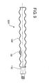
- FIG. 9 A further embodiment of the present invention of a rotor 30A constructed in accordance with the teachings of the invention is shown in Figure 9.
- the rotor will operate in a stator housing an internal helical cavity.
- the rotor 30A has a helical mandrel 98 composed of metal. It will be understood that the mandrel 98 may alternately be composed of plastic or composite material.
- Surrounding the mandrel 98 is a layer or outer covering of elastomeric or resilient material 100 .
- the layer of outer covering of elastomeric material may be nitryl rubber, butyl rubber, polyurethane or other elastomeric material that will withstand elevated temperatures and corrosive environments.
- a .125 inch thick layer of elastomeric or resilient material is bonded to the rotor surface. Such bonding can be through thermal, chemical compression or other well known adhesive methods.
Landscapes
- Engineering & Computer Science (AREA)
- Mechanical Engineering (AREA)
- General Engineering & Computer Science (AREA)
- Rotary Pumps (AREA)
Abstract

Description
- This invention relates to improvements in progressive cavity style devices of the type composed of a helicoidal rotor acting with a complimentary helicoidal stator and also well known as a "Moineau pump" which may be used as a pump or as a motor to drive other equipment.
- Progressive cavity helical devices have been known since their invention was disclosed in U.S. Patent No. 1,892,217, entitled "Gear Mechanism" to Moineau. The helicoidal rotor and the stator engage with each other along a sealing line to create cavities which progress axially as the rotor is rotated relative to the stator. Because of the required sealing and sliding contact concept of a Moineau pump, the stator and the rotor become subject to extensive wear, which necessitates frequent replacement of the stator and/or the rotor. Commercially available Moineau pumps, as well as those disclosed in the prior art, require extensive disassembly of the pumping apparatus to replace the worn stator and/or rotor, in addition to the down time loss of use. In a pump device, rotary motion is applied to the rotor which causes fluids and solids to be passed therethrough. Where the progressive cavity device is used as a motor, one method is to apply fluid pressure to the cavity to cause the rotor to rotate, the power therefrom having many uses. In the case of use in drilling wells, the ability to decrease the frequency of down time and extend the useful life of the motor is a desired objective.
- In a progressive cavity pump or motor, problems arise because the axial centerline of the rotor is required to orbit or gyrate relative to the centerline of the stator. Thus, there is a great deal of flexture that must be accounted for to obtain long life of parts. The prior art is filled with various types of universal joints, flexible shafts, and mechanical connections to compensate for the orbital or gyrating type of motion. Many of these are disclosed in U.S. Patents 4,923,376 and 2,739,650.
- Heretofore, the conventional Moineau pump and motor art has used rubber or elastomer materials bonded to steel for the stator contact surface. Such elastomers include not only natural rubber, but also synthetics, such as G.R.S., neoprene, butyl and nitrile rubbers, although there are other types such as soft PVC. The key, of course, is to make the elastomer property soft enough to maintain the sealed cavity, yet be hard enough to withstand the abrasive wear from the working contact between the rotor and the stator. The rotor in these instances is usually made of steel. Some efficiency of the pump/motor is lost because the elastomer mold must be thicker at the peaks of the helicoid in order to create the progressive cavity. This lack of uniform thickness creates compressibility differences which, at increasing pressures, causes bypass of the fluids being pumped. Thus, the pump/motor reaches a point where it is less efficient at ever increasing pressure. Because of the different thicknesses, there are different expansion characteristics and different rates and the pump does more work and builds up heat from the friction.
- Rubber used as the stator contact surface is not preferable in high temperature environments because of its low heat conductivity. In addition, as progressive cavity devices increase in diameter and/or length, flow characteristics to maintain a successful and long lasting bond of the rubber to a steel housing becomes more difficult. Also, where hydrocarbons make up the material to be pumped, such as in oil producing wells, rubber is known to deteriorate. One attempt to overcome these problems is taught in U.S. Patent 3,912,426 by using multiple stators connected in series with separate but connected rotors for each stator. The stators surfaces, however, are still composed of rubber.
- Moineau type rotor and stator devices have been used heretofore for downhole drilling motors for drilling straight or deviated boreholes in earth formations. For instance, see the following U.S. Patents: 3,840,080, 3,912,426, 4,415,316, 4,636,151, 5,090,497, 5,171,138
- In applicant's prior U.S. Patents 5,417,281 and 5,759,019, composites are taught for the progressive cavity pump/motor parts and for the tubing used to carry fluids to the progressive cavity pump.
- In the prior art references, there is no teaching of using composites as defined herein in Moineau type motors wherein at least one of the stator and rotor is comprised of a composite material. U. S. Patent No. 5,759,019 teaches such use in pumps while pending application, Serial No.08/979,290, teaches such use in motors.
- There remains a need for a progressive cavity helical device having a stator with an internal helical cavity and a helical rotor within the internal helical cavity of the stator wherein the rotor has a mandrel made of metal, plastic or composite material and an outer covering of elastomeric or resilient material.
- It is an overall object of the present invention to disclose new forms of stators, rotors and flex shafts for increasing the efficiency and longevity of progressive cavity helical devices. To that end, a primary object of this invention is to provide the use of elastomers or resilient material in the makeup of the rotor of progressive cavity helical devices.
- Another object is to provide a progressive cavity helical device manufactured according to this invention which is capable of use in not only downhole drilling of well bores but for other above ground industrial applications.
- Another object of the invention is to provide a progressive cavity helical device in which the output power is available from either end of a rotor. In all cases, the rotary power is derived by forcing fluid to flow into the cavity between the stator and rotor from an inlet to an outlet delivering rotary power at the end or ends of the rotor.
- In a first aspect of the invention there is provided a progressive cavity helical device which comprises: a stator with an internal helical cavity; a helical rotor within said internal helical cavity of said stator, said rotor having a non-resilient composite material formed of a plurality of filament fibers impregnated with a thermal setting resin; and an outer covering of elastomeric or resilient material bonded to said mandrel.
- In one embodiment the elastomeric or resilient material is nitryl rubber.
- In one embodiment the elastomeric or resilient material is butyl rubber or alternatively can be polyurethane.
- Specific embodiments of the invention are now described with reference to the accompanying drawings wherein;
- FIGURE 1 is a sectional and schematic view of a typical progressive cavity motor according to this invention as used in downhole drilling.
- FIGURE 2 is a sectional view taken along the line 2-2 of Figure 1.
- FIGURE 3 is a sectional view of another form of progressive cavity motor according to the invention.
- FIGURE 4 is a sectional and schematic view of another embodiment of progressive cavity motor according to this invention.
- FIGURE 5 is an elevational view of a composite combination flex shaft and rotor formed as one component.
- FIGURE 6 is an elevational view of a composite rotor formed separately from the flex shaft.
- FIGURE 7 is a view describing one method of forming a flex shaft and/or rotor for a progressive cavity motor.
- FIGURE 8 is an elevational view of an alternate form of flex shaft with a built-in flex point.
- FIGURE 9 is an elevational and sectional view of one type of rotor having a metal mandrel and a resilient, elastomer covering constructed in accordance with the present invention.
-
- While the invention has been described with a certain degree of particularity, it is manifest that many changes may be made in the details of construction and the arrangement of components without departing from the spirit and scope of this disclosure. It is understood that the invention is not limited to the embodiment set forth herein for purposes of exemplification, but is to be limited only by the scope of the attached claim or claims, including the full range of equivalency to which each element thereof is entitled.
- Figure 1 is a simple representative of a typical progressive cavity or Moineau type motor according to this invention. Such motors include a
basic housing 10 through which power fluid enters at 12 into thecavities 28 formed between the rotor and stator to create the rotary motion of the rotor. Specifically, the motor is made up of thehelicoid stator 20, and a matedhelicoid rotor 30. The rotor includes aflex shaft 40, which in this embodiment is supported bybearings 42 and packing as needed. The pressure fluid exits through or arounddrill bit 56 viaports 58. Theflex shaft 40 and appropriate bearing supports must translate the rotation and gyration ofrotor 30 to true rotary motion ofshaft 40 which is imported to, in this instance,drill bit 56. Theflex shaft 40 must be able to withstand the motor thrust and torque loads, yet be flexible to the gyrational and eccentric motion ofrotor 30. Drill pipe bearing support systems as found in U.S. Patents 4,636,151 and 3,840,080 are inclusive for use with this aspect of the invention. The invention herein is directed for use in all forms of progressive cavity motor applications, the specific invention being in the makeup of the stator and/or the rotor and/or flex shaft utilizing composite materials. - Composite materials are typically defined to include carbon fibers, boron fibers, ceramic fibers, glass fibers, thermoplastic fibers, natural fibers, metallic fibers, fibrous reinforced and synthetic fibers, all of which are typically impregnated with thermal setting resins. Typical of such thermal setting resins are the alkyd polyesters, general purpose epoxy, general purpose phenolic and urea-formaldehyde compositions.
- The stator formulations of this invention are best described herein with reference to the cross-section shown in Figures 2 and 3 which are used herein to describe the various alternate embodiments by reference to those portions of the stator identified as 22, 24 and 26, the latter being the surface by which the
rotor 30 will sealably function within thecavities 28. The various stator embodiments are capable of being formed by a variety of methods, including molding and/or machining and thus, provide formulations that can be adapted to a variety of motor uses and environments. Although the drawings indicate the use of anouter housing 10, it is to be understood that in some usages the invention herein could be made up utilizing the stator area without theouter housing 10. - In embodiment A,
stator 20 is comprised ofareas helicoid interface 26 of a rubber elastomer. Therotor 30, is comprised of steel or composite materials as hereinafter described.Areas - In embodiment B,
areas helicoid liner 26 is a thermoplastic resin. - In embodiment C, composite material will make up the total stator, including
areas - In embodiment D,
areas inner lining 26 being formulated of a composite material. - In embodiment E the
supportive structure rotor contact surface 26 being of composite material having little or no elastomeric properties. Such a stator of this embodiment will provide an improved sealing and wear surface between the rotor and stator surfaces, thereby increasing mechanical efficiency as well as reducing heat during the motor action. This construction allows for expansion and contraction of the stator parts together, since the thermal transfer coefficient of the composite is higher and capable of wicking off the resulting frictional heat caused by the rotor to stator action. - In
Embodiment F areas rotor contact surface 26 being a bonded composite material. In this embodiment, the elastomer becomes protected from any deteriorating or abrasive produced fluids and solids and destructive friction between the rotor and stator. - Referring now to Figure 3, a combination stator and rotor is configured in a variety of manners. In one embodiment, the stator
inner face 26 would be of a composite having elastomeric properties with the supportingouter zones 22/24 being a non-compressible composite for use with rotors of steel or non-compressible composite. Various combinations are possible when therotor 30A is of two part construction of aninner core 98 andouter surface 100. For instance, if theinner core 98 is a non-compressible composite and theouter surface 100 elastomeric composite or rubber, the preferredstator comprising areas core 98 is an elastomeric composite and theouter surface 100 is a non-elastomeric composite, thestator 30elements surface 26 made of an elastomeric composite, whilearea - An alternate embodiment is shown in Figure 4 wherein the power from the rotor may be taken off of at one or both ends as may be applicable to an industrial need. Like number refer to like parts previously described. In this embodiment the
housing 10 includes sealed thrust androtary bearing closures devices conduit 13. - In one embodiment of this invention for use with any of the stator embodiments, the rotor may be steel or formed of a composite material. Another embodiment is to form the
rotor 30, and the flex shaft(s) 40 and/or 50 as a single unitary member such as shown in Figure 5 wherein theflex shaft 40A is combined with a connectingmeans 42. In another embodiment, a separate rotor as shown in Figure 6 includes means such as threaded bore 60 which can be attached to a separately made flex shaft. The rotor and the flex shaft can be formed in a variety of ways such as utilizing a resin transfer mold (RTM) for making complex configurations. One method of forming a flex shaft and/or rotor is shown in Figure 7. Metal orcomposite end fittings portion inner shoulders cylindrical portions mandrel 80.Mandrel 80 may be any form of material, plastic or metal and is used to assemble the parts and provide support for the process of forming the composite structure of the flex shaft. Themandrel 80 is to have flexibility in and of itself. After assembly ofparts composite fibers 86 in one angular direction andfibers 88 in the opposite direction, typically 45° as shown, or by rotating the fibers around a fixed mandrel, until the height thereof matches the outer diameter offlanges composite - Another embodiment of flex shaft is shown in Figure 8 being so constructed to create a
flex point 94 formed as a concave indentation less than diameter D. The location of the flex point will vary with the characteristics of the motor including size. The flex point can be formed by changing, via computer controlled means, the angular direction of the composite fibers and/or resin materials at the point or area where flex is desired. For instance, during a filament winding at +45° and -45° up to section 96 (Fig. 7), the angular direction would be changed to angles less than 45° to create a flex section without decreasing overall diameter D. - Ordinarily, the flex shaft and rotor used in progressive cavity motors are made of steel. Utilizing a composite flex shaft permits the use of materials which are anti-isotropic. To make a steel flex shaft more flexible consists of either reducing the wall thickness or making the diameter smaller. Both of these methods reduce the strength of a metallic flex shaft, especially to fatigue. Utilization of a type of composite fiber and the alignment of these fibers permits a larger wall thickness while providing maximum strength and maximum flexibility required in the eccentric orbital motion. Composite materials are inherently better in fatigue application than metals, nor will they rust, corrode or react with the chemicals found in oil production environment; yet, the materials can be used in environments exceeding 600°F (315°C). Overall, the strength, fatigue and stiffness of composite materials are found to be equal to and in most cases exceeding the specifications of metals, including titanium, steel, aluminum, etc.
- The terms "elastomeric" or "resilient" as used with reference to composites is accomplished by variations in the composite fibers and/or the resin formulations to achieve the desired characteristic. For example, HELOXY flexablizer by Shell Chemical Co. is added to the DPL-862 epoxy resin in an amount within the range of 20-40% by weight. This is then mixed with a hardener and TEFLON® powder in an amount to maintain a workable (flowable) mixture which is then applied to the fiber in the formation of a stator and/or rotor. The resulting composite is oven cured at 300-400°F (150-200°C) for approximately four hours.
- A further embodiment of the present invention of a
rotor 30A constructed in accordance with the teachings of the invention is shown in Figure 9. The rotor will operate in a stator housing an internal helical cavity. Therotor 30A has ahelical mandrel 98 composed of metal. It will be understood that themandrel 98 may alternately be composed of plastic or composite material. Surrounding themandrel 98 is a layer or outer covering of elastomeric orresilient material 100. The layer of outer covering of elastomeric material may be nitryl rubber, butyl rubber, polyurethane or other elastomeric material that will withstand elevated temperatures and corrosive environments. In one embodiment, a .125 inch thick layer of elastomeric or resilient material is bonded to the rotor surface. Such bonding can be through thermal, chemical compression or other well known adhesive methods. - Whereas, the present invention has been described in relation to the drawings attached hereto, it should be understood that other and further modifications, apart from those shown or suggested herein, may be made within the spirit and scope of this invention.
Claims (4)
- A progressive cavity helical device which comprises:a stator with an internal helical cavity;a helical rotor within said internal helical cavity of said stator, said rotor having a non-resilient composite material formed of a plurality of filament fibers impregnated with a thermal setting resin; andan outer covering of elastomeric or resilient material bonded to said mandrel.
- A progressive cavity helical device as set forth in Claim 1 wherein said elastomeric or resilient material is nitryl rubber.
- A progressive cavity helical device as set forth in Claim 1 wherein said elastomeric or resilient material is butyl rubber.
- A progressive cavity helical device as set forth in Claim 1 wherein said elastomeric or resilient material is polyurethane.
Priority Applications (1)
| Application Number | Priority Date | Filing Date | Title |
|---|---|---|---|
| EP20020256992 EP1406016A1 (en) | 2002-10-04 | 2002-10-04 | Progressive cavity pumps using composite materials |
Applications Claiming Priority (1)
| Application Number | Priority Date | Filing Date | Title |
|---|---|---|---|
| EP20020256992 EP1406016A1 (en) | 2002-10-04 | 2002-10-04 | Progressive cavity pumps using composite materials |
Publications (1)
| Publication Number | Publication Date |
|---|---|
| EP1406016A1 true EP1406016A1 (en) | 2004-04-07 |
Family
ID=31985141
Family Applications (1)
| Application Number | Title | Priority Date | Filing Date |
|---|---|---|---|
| EP20020256992 Withdrawn EP1406016A1 (en) | 2002-10-04 | 2002-10-04 | Progressive cavity pumps using composite materials |
Country Status (1)
| Country | Link |
|---|---|
| EP (1) | EP1406016A1 (en) |
Cited By (8)
| Publication number | Priority date | Publication date | Assignee | Title |
|---|---|---|---|---|
| WO2009062717A2 (en) * | 2007-11-15 | 2009-05-22 | Services Petroliers Schlumberger | Work extraction from downhole progressive cavity devices |
| WO2009087475A2 (en) * | 2007-12-31 | 2009-07-16 | Schlumberger Canada Limited | High temperature progressive cavity motor or pump component and method of fabrication |
| US9045942B2 (en) | 2012-06-20 | 2015-06-02 | Drilformance Technologies, Llc | Downhole motor assembly |
| FR3020097A1 (en) * | 2014-04-22 | 2015-10-23 | Pcm | ADVANCED CAVITY PUMP |
| US9441627B2 (en) | 2012-11-01 | 2016-09-13 | National Oilwell Varco, L.P. | Lightweight and flexible rotors for positive displacement devices |
| US10480506B2 (en) | 2014-02-18 | 2019-11-19 | Vert Rotors Uk Limited | Conical screw machine with rotating inner and outer elements that are longitudinally fixed |
| US10844663B2 (en) | 2012-02-21 | 2020-11-24 | Smith International, Inc. | Fiber reinforced elastomeric stator |
| CN116201728A (en) * | 2022-12-22 | 2023-06-02 | 华创机器人制造有限公司 | Special screw pump for submersible screw pump oil extraction machine and manufacturing method |
Citations (12)
| Publication number | Priority date | Publication date | Assignee | Title |
|---|---|---|---|---|
| US1892217A (en) | 1930-05-13 | 1932-12-27 | Moineau Rene Joseph Louis | Gear mechanism |
| US2739650A (en) | 1951-09-19 | 1956-03-27 | Perfect Circle Corp | Pumping apparatus |
| US3840080A (en) | 1973-03-26 | 1974-10-08 | Baker Oil Tools Inc | Fluid actuated down-hole drilling apparatus |
| US3912426A (en) | 1974-01-15 | 1975-10-14 | Smith International | Segmented stator for progressive cavity transducer |
| US4415316A (en) | 1980-05-21 | 1983-11-15 | Christensen, Inc. | Down hole motor |
| US4636151A (en) | 1985-03-13 | 1987-01-13 | Hughes Tool Company | Downhole progressive cavity type drilling motor with flexible connecting rod |
| US4923376A (en) | 1988-03-24 | 1990-05-08 | Wright John L | Moineau pump with rotating closed end outer member and nonrotating hollow inner member |
| US5090497A (en) | 1990-07-30 | 1992-02-25 | Baker Hughes Incorporated | Flexible coupling for progressive cavity downhole drilling motor |
| US5171138A (en) | 1990-12-20 | 1992-12-15 | Drilex Systems, Inc. | Composite stator construction for downhole drilling motors |
| US5417281A (en) | 1994-02-14 | 1995-05-23 | Steven M. Wood | Reverse Moineau motor and pump assembly for producing fluids from a well |
| WO1997040273A1 (en) * | 1996-04-24 | 1997-10-30 | Wood Steven M | Progressive cavity pumps using composite materials |
| US20010005486A1 (en) * | 1996-04-24 | 2001-06-28 | Wood Steven M. | Progressive cavity helical device |
-
2002
- 2002-10-04 EP EP20020256992 patent/EP1406016A1/en not_active Withdrawn
Patent Citations (13)
| Publication number | Priority date | Publication date | Assignee | Title |
|---|---|---|---|---|
| US1892217A (en) | 1930-05-13 | 1932-12-27 | Moineau Rene Joseph Louis | Gear mechanism |
| US2739650A (en) | 1951-09-19 | 1956-03-27 | Perfect Circle Corp | Pumping apparatus |
| US3840080A (en) | 1973-03-26 | 1974-10-08 | Baker Oil Tools Inc | Fluid actuated down-hole drilling apparatus |
| US3912426A (en) | 1974-01-15 | 1975-10-14 | Smith International | Segmented stator for progressive cavity transducer |
| US4415316A (en) | 1980-05-21 | 1983-11-15 | Christensen, Inc. | Down hole motor |
| US4636151A (en) | 1985-03-13 | 1987-01-13 | Hughes Tool Company | Downhole progressive cavity type drilling motor with flexible connecting rod |
| US4923376A (en) | 1988-03-24 | 1990-05-08 | Wright John L | Moineau pump with rotating closed end outer member and nonrotating hollow inner member |
| US5090497A (en) | 1990-07-30 | 1992-02-25 | Baker Hughes Incorporated | Flexible coupling for progressive cavity downhole drilling motor |
| US5171138A (en) | 1990-12-20 | 1992-12-15 | Drilex Systems, Inc. | Composite stator construction for downhole drilling motors |
| US5417281A (en) | 1994-02-14 | 1995-05-23 | Steven M. Wood | Reverse Moineau motor and pump assembly for producing fluids from a well |
| US5759019A (en) | 1994-02-14 | 1998-06-02 | Steven M. Wood | Progressive cavity pumps using composite materials |
| WO1997040273A1 (en) * | 1996-04-24 | 1997-10-30 | Wood Steven M | Progressive cavity pumps using composite materials |
| US20010005486A1 (en) * | 1996-04-24 | 2001-06-28 | Wood Steven M. | Progressive cavity helical device |
Cited By (15)
| Publication number | Priority date | Publication date | Assignee | Title |
|---|---|---|---|---|
| WO2009062717A3 (en) * | 2007-11-15 | 2009-09-24 | Services Petroliers Schlumberger | Work extraction from downhole progressive cavity devices |
| WO2009062717A2 (en) * | 2007-11-15 | 2009-05-22 | Services Petroliers Schlumberger | Work extraction from downhole progressive cavity devices |
| CN101960145B (en) * | 2007-12-31 | 2013-09-11 | 普拉德研究及开发股份有限公司 | High temperature progressive cavity motor or pump component and method of fabrication |
| WO2009087475A3 (en) * | 2007-12-31 | 2009-11-19 | Schlumberger Canada Limited | High temperature progressive cavity motor or pump component and method of fabrication |
| RU2459088C2 (en) * | 2007-12-31 | 2012-08-20 | Шлюмбергер Текнолоджи Б.В. | Drive and stator element, and rotor of electric motor with movable cavity, and stator and rotor manufacturing methods |
| US8444901B2 (en) | 2007-12-31 | 2013-05-21 | Schlumberger Technology Corporation | Method of fabricating a high temperature progressive cavity motor or pump component |
| WO2009087475A2 (en) * | 2007-12-31 | 2009-07-16 | Schlumberger Canada Limited | High temperature progressive cavity motor or pump component and method of fabrication |
| US10844663B2 (en) | 2012-02-21 | 2020-11-24 | Smith International, Inc. | Fiber reinforced elastomeric stator |
| US9045942B2 (en) | 2012-06-20 | 2015-06-02 | Drilformance Technologies, Llc | Downhole motor assembly |
| US9441627B2 (en) | 2012-11-01 | 2016-09-13 | National Oilwell Varco, L.P. | Lightweight and flexible rotors for positive displacement devices |
| US10480506B2 (en) | 2014-02-18 | 2019-11-19 | Vert Rotors Uk Limited | Conical screw machine with rotating inner and outer elements that are longitudinally fixed |
| US10962004B2 (en) | 2014-02-18 | 2021-03-30 | Vert Rotors Uk Limited | Synchronized conical screw compressor or pump |
| FR3020097A1 (en) * | 2014-04-22 | 2015-10-23 | Pcm | ADVANCED CAVITY PUMP |
| CN116201728A (en) * | 2022-12-22 | 2023-06-02 | 华创机器人制造有限公司 | Special screw pump for submersible screw pump oil extraction machine and manufacturing method |
| CN116201728B (en) * | 2022-12-22 | 2024-02-13 | 华创机器人制造有限公司 | Special screw pump for submersible screw pump oil extraction machine and manufacturing method |
Similar Documents
| Publication | Publication Date | Title |
|---|---|---|
| CA2397164C (en) | Progressive cavity helical device | |
| US6183226B1 (en) | Progressive cavity motors using composite materials | |
| CA2251112C (en) | Progressive cavity pumps using composite materials | |
| EP1333151B1 (en) | Liner of optimized thickness for positive displacement drilling motors | |
| RU2602856C2 (en) | Volume type engine with radially limited rotor engagement | |
| US10450800B2 (en) | Bearing/gearing section for a PDM rotor/stator | |
| US20130048384A1 (en) | Apparatus and method for controlling or limiting rotor orbit in moving cavity motors and pumps | |
| US3975120A (en) | Wafer elements for progressing cavity stators | |
| RU2318135C1 (en) | Stator of screw gerotor hydraulic machine | |
| RU2733589C1 (en) | Downhole motor manufacturing method | |
| EP1406016A1 (en) | Progressive cavity pumps using composite materials | |
| EP2855823A1 (en) | Apparatus and method for controlling or limiting rotor orbit in moving cavity motors and pumps | |
| GB2525500B (en) | Asymmetric lobes for motors and pumps | |
| US11795761B2 (en) | Positive displacement motor with a thermoplastic stator that can be replaceable | |
| RU2315201C1 (en) | Stator of screw gyrator hydraulic machine |
Legal Events
| Date | Code | Title | Description |
|---|---|---|---|
| PUAI | Public reference made under article 153(3) epc to a published international application that has entered the european phase |
Free format text: ORIGINAL CODE: 0009012 |
|
| AK | Designated contracting states |
Kind code of ref document: A1 Designated state(s): AT BE BG CH CY CZ DE DK EE ES FI FR GB GR IE IT LI LU MC NL PT SE SK TR |
|
| AX | Request for extension of the european patent |
Extension state: AL LT LV MK RO SI |
|
| 17P | Request for examination filed |
Effective date: 20040906 |
|
| AKX | Designation fees paid |
Designated state(s): AT BE BG CH CY CZ DE DK EE ES FI FR GB GR IE IT LI LU MC NL PT SE SK TR |
|
| 17Q | First examination report despatched |
Effective date: 20050401 |
|
| STAA | Information on the status of an ep patent application or granted ep patent |
Free format text: STATUS: THE APPLICATION HAS BEEN WITHDRAWN |
|
| 18W | Application withdrawn |
Effective date: 20050713 |