JP2017181007A - Blockage suppression device and blockage suppression method for boiler - Google Patents
Blockage suppression device and blockage suppression method for boiler Download PDFInfo
- Publication number
- JP2017181007A JP2017181007A JP2016073483A JP2016073483A JP2017181007A JP 2017181007 A JP2017181007 A JP 2017181007A JP 2016073483 A JP2016073483 A JP 2016073483A JP 2016073483 A JP2016073483 A JP 2016073483A JP 2017181007 A JP2017181007 A JP 2017181007A
- Authority
- JP
- Japan
- Prior art keywords
- pressure
- boiler
- heat transfer
- pressure wave
- exhaust gas
- Prior art date
- Legal status (The legal status is an assumption and is not a legal conclusion. Google has not performed a legal analysis and makes no representation as to the accuracy of the status listed.)
- Pending
Links
Images


Abstract
Description
本発明は、ボイラの伝熱管に付着したダストによるボイラの閉塞抑制装置及び閉塞抑制方法に係り、特に、発電設備を有するごみ焼却施設に用いるのに好適な、ボイラ閉塞抑制装置及び閉塞抑制方法に関する。 The present invention relates to a boiler blockage suppression device and a blockage suppression method due to dust adhering to a heat transfer tube of a boiler, and more particularly to a boiler blockage suppression device and a blockage suppression method suitable for use in a garbage incineration facility having a power generation facility. .
発電設備を有するごみ焼却施設の運営において、発電量・売電量の維持と向上は、ごみの安定処理に次ぐ最重要項目のひとつである。ごみ焼却施設における発電は、焼却炉でのごみの燃焼から得られる高温の排ガスからボイラにて熱回収を行い、所定の温度・圧力の蒸気を発生させてタービン発電機に導入することにより行われている。ボイラは、排ガスからの放射熱を受けて蒸気を発生させる放射伝熱面を備える放射室、排ガスと伝熱管の対流伝熱面との熱交換により蒸気を発生し更に過熱する対流伝熱室とを備えている。 In the operation of a waste incineration facility with power generation facilities, maintaining and improving the amount of power generated and sold is one of the most important items after the stable treatment of waste. Power generation at a waste incineration facility is performed by recovering heat from a high-temperature exhaust gas obtained from the combustion of waste in an incinerator and generating steam at a predetermined temperature and pressure and introducing it into a turbine generator. ing. The boiler has a radiant chamber having a radiant heat transfer surface that generates steam by receiving radiant heat from the exhaust gas, a convection heat transfer chamber that generates steam by heat exchange between the exhaust gas and the convective heat transfer surface of the heat transfer tube, and further superheats. It has.
放射室には、排ガス流路を囲む鋼製側壁の外側に加温水を流通させ放射加熱により蒸気を発生させる放射伝熱管が放射伝熱面として配設されている。対流伝熱室には、排ガス流路内に排ガスと接触して対流伝熱により蒸気を発生させ更に過熱する伝熱管(過熱器とも称する)が対流伝熱面として配設されている。対流伝熱面は水平方向に伝熱管が複数配設された伝熱管群が高さ方向に複数段配設されて構成されている。対流伝熱室には、排ガス流路内に水を加熱して加温水とする伝熱管を有するエコノマイザが配設されることがある。また、ボイラの下流側にボイラに供給する水を加熱するために排ガス流路内に水を加熱して加温水とする伝熱管を有する別置エコノマイザが連設されることもある。 In the radiant chamber, a radiant heat transfer tube is provided as a radiant heat transfer surface through which heated water is circulated on the outside of the steel side wall surrounding the exhaust gas flow path to generate steam by radiant heating. In the convection heat transfer chamber, a heat transfer tube (also referred to as a superheater) that contacts the exhaust gas in the exhaust gas flow path to generate steam by convective heat transfer and further superheats is disposed as a convection heat transfer surface. The convection heat transfer surface is configured by arranging a plurality of heat transfer tube groups in which a plurality of heat transfer tubes are arranged in the horizontal direction in the height direction. The convection heat transfer chamber may be provided with an economizer having a heat transfer tube that heats water in the exhaust gas flow path to produce heated water. Moreover, in order to heat the water supplied to a boiler in the downstream of a boiler, the separate economizer which has a heat exchanger tube which heats water in an exhaust gas flow path and makes it warm water may be provided in series.
ごみ焼却において発生する排ガス中には、塩素・硫黄・重金属類等を含む小粒径のダストが含まれるが、これらがボイラの放射伝熱面、対流伝熱面に付着すると、その付着ダストが断熱材の役割をするので伝熱効率が低下する。それにより、熱回収効率も低下する。その結果、蒸気発生量が低下し、タービン発電機の発電量が減少する。その他にも、伝熱管同士の間隙が付着ダストにより閉塞し、排ガスの流通に支障が生じることもある。 The exhaust gas generated in refuse incineration contains dust of small particle size including chlorine, sulfur, heavy metals, etc., but if these adhere to the radiant and convective heat transfer surfaces of the boiler, the adhering dust will be Since it acts as a heat insulating material, heat transfer efficiency decreases. Thereby, the heat recovery efficiency also decreases. As a result, the amount of steam generated decreases, and the amount of power generated by the turbine generator decreases. In addition, the gap between the heat transfer tubes may be blocked by adhering dust, which may hinder the flow of exhaust gas.
このため、付着したダストを定期的に除去する設備が必要となる。対流伝熱面に付着するダストを除去する技術として、石炭ボイラや多くのボイラでの実績のある装置として蒸気式スートブロワ(特許文献1参照)が挙げられる。蒸気式スートブロワは複数のノズルから水蒸気を伝熱管に向けて噴射し、伝熱管表面に付着したダストを剥離し除去するもので、定期的なタイミングで水蒸気を噴射する。 For this reason, the equipment which removes adhering dust regularly is needed. As a technique for removing dust adhering to the convection heat transfer surface, a steam soot blower (see Patent Document 1) is known as an apparatus that has a proven record in coal boilers and many boilers. The steam soot blower injects water vapor from a plurality of nozzles toward the heat transfer tube, and peels and removes dust adhering to the surface of the heat transfer tube, and injects water vapor at a regular timing.
廃棄物焼却炉から排出される排ガスには、廃棄物に含まれる成分と排ガス中の塩化水素との反応により生成した塩化物が含まれている。これらの塩化物としては塩化カリウム、塩化ナトリウムが一般的に挙げられ、さらに、廃棄物に鉛や亜鉛が含まれる場合には、塩化鉛、塩化亜鉛が挙げられる。これらの塩化物の融点、沸点は以下のとおりである。
塩化カリウムと塩化ナトリウムの1:1混合塩の融点:657℃
塩化鉛の融点:501℃
塩化鉛の沸点:950℃
塩化亜鉛の融点:275℃
塩化亜鉛の沸点:756℃
The exhaust gas discharged from the waste incinerator includes chloride generated by the reaction between the components contained in the waste and hydrogen chloride in the exhaust gas. These chlorides generally include potassium chloride and sodium chloride. Furthermore, when the waste contains lead and zinc, lead chloride and zinc chloride are exemplified. The melting points and boiling points of these chlorides are as follows.
Melting point of 1: 1 mixed salt of potassium chloride and sodium chloride: 657 ° C
Melting point of lead chloride: 501 ° C
Boiling point of lead chloride: 950 ° C
Melting point of zinc chloride: 275 ° C
Boiling point of zinc chloride: 756 ° C
一般的な廃棄物焼却炉において、焼却炉出口の排ガス温度は900℃以上であるため、これらの塩化物は排ガス中に液体あるいは気体の状態で含まれ、ボイラに流入する。排ガスはボイラの放射室内に設けられた水冷壁で構成される放射伝熱面で熱回収されて温度が低下し、下流側の過熱器伝熱管群が設置されている対流伝熱室の入口で温度が約600〜650℃となる。この対流伝熱室の入口の温度雰囲気は、塩化カリウム・塩化ナトリウム混合塩の融点以下であるため、混合塩は固体状態で存在する。また、塩化鉛や塩化亜鉛は、この温度雰囲気が融点と沸点の間の領域に当るため、液体と気体の混合物となっている。 In a general waste incinerator, since the exhaust gas temperature at the incinerator outlet is 900 ° C. or higher, these chlorides are contained in the exhaust gas in a liquid or gas state and flow into the boiler. The exhaust gas is recovered by heat at the radiant heat transfer surface consisting of water-cooled walls provided in the radiant chamber of the boiler, the temperature drops, and at the entrance of the convection heat transfer chamber where the downstream superheater heat transfer tube group is installed. The temperature is about 600-650 ° C. Since the temperature atmosphere at the inlet of the convection heat transfer chamber is lower than the melting point of the potassium chloride / sodium chloride mixed salt, the mixed salt exists in a solid state. In addition, lead chloride and zinc chloride are a mixture of liquid and gas because this temperature atmosphere is in the region between the melting point and boiling point.
排ガスが対流伝熱室の過熱器伝熱管群やエコノマイザ伝熱管群を通過して熱回収される際に、排ガス温度は徐々に低下し、エコノマイザ出口では170〜250℃にまで低下する。排ガスが対流伝熱室の入口から対流伝熱室の出口あるいはエコノマイザ出口まで流通する間に、排ガス温度の低下に伴って塩化鉛や塩化亜鉛の液体と気体の混合物は、液体の存在割合が増加し、その液体は過熱器伝熱管あるいはエコノマイザ伝熱管表面に付着する。これらの伝熱管表面に付着した塩化鉛や塩化亜鉛は液体状態であるため、他の飛散ダストが付着しやすく、時間経過に伴って伝熱管表面に付着ダスト層が形成される。この付着ダスト層の厚さが増加すると伝熱管の間隙が狭くなりボイラが閉塞することとなる。 When the exhaust gas passes through the superheater heat transfer tube group and the economizer heat transfer tube group in the convection heat transfer chamber and is heat-recovered, the exhaust gas temperature gradually decreases and decreases to 170 to 250 ° C. at the economizer outlet. While the exhaust gas flows from the convection heat transfer chamber inlet to the convection heat transfer chamber outlet or economizer outlet, the liquid / gas mixture of lead chloride and zinc chloride increases as the exhaust gas temperature decreases. The liquid adheres to the surface of the superheater heat transfer tube or the economizer heat transfer tube. Since lead chloride and zinc chloride adhering to these heat transfer tube surfaces are in a liquid state, other scattered dust tends to adhere, and an adhering dust layer is formed on the heat transfer tube surface over time. When the thickness of the adhering dust layer increases, the gap between the heat transfer tubes is narrowed and the boiler is closed.
特に、鉛や亜鉛の含有量の多い廃棄物を焼却炉に投入する場合、排ガス中の塩化鉛や塩化亜鉛の含有率が高く、ボイラの過熱器伝熱管群やエコノマイザ伝熱管群に付着する液体状の塩化鉛や塩化亜鉛量が増加する。そのため、過熱器伝熱管やエコノマイザ伝熱管表面の付着ダスト層の厚さが増加する速度が速くなる。通常、ボイラの伝熱管に付着したダストを除去するためには、12〜24時間間隔で蒸気を噴射するスートブロワが広く用いられているが、このような蒸気式スートブロワを用いても除去しきれないほどに付着ダスト層の厚さが増加して伝熱管の間隙が埋まり、排ガス流通経路が狭くなり、やがてボイラが閉塞する。そうなると、排ガスを煙突に導くことが不可能になり、焼却炉を緊急停止することとなるため、計画的な廃棄物焼却処理ができなくなるという問題が生じる。また、ボイラの閉塞を回避するために蒸気式スートブロワの運転間隔を短くすると、スートブロワで噴射するために多量の蒸気を消費することになり、タービン発電機に導入する蒸気量が減少して発電量が低下するという問題も生じる。 In particular, when waste with a high content of lead or zinc is thrown into the incinerator, the content of lead chloride or zinc chloride in the exhaust gas is high, and the liquid adheres to the boiler superheater heat exchanger tube group or economizer heat transfer tube group The amount of lead chloride and zinc chloride increases. Therefore, the speed at which the thickness of the adhered dust layer on the superheater heat transfer tube or the economizer heat transfer tube surface increases. Usually, in order to remove dust adhering to the heat transfer tube of a boiler, a soot blower that injects steam at intervals of 12 to 24 hours is widely used. However, even if such a steam type soot blower is used, it cannot be completely removed. As the thickness of the adhering dust layer increases, the gap between the heat transfer tubes is filled, the exhaust gas flow path is narrowed, and the boiler is eventually closed. In this case, exhaust gas cannot be guided to the chimney, and the incinerator is urgently stopped, which causes a problem that planned waste incineration processing cannot be performed. Moreover, if the operation interval of the steam soot blower is shortened in order to avoid the blockage of the boiler, a large amount of steam is consumed to inject with the soot blower, and the amount of steam introduced into the turbine generator decreases, resulting in a reduction in power generation amount. There is also a problem of lowering.
本発明は、以上のような状況に鑑みてなされたもので、廃棄物焼却炉に連設されるボイラ内の対流伝熱室の過熱器伝熱管群やエコノマイザ伝熱管群に付着する付着ダスト層の形成によって生じるボイラの閉塞の抑制を、効率よくかつ低い設備費、運転費で行うことができるボイラの閉塞抑制装置及び閉塞抑制方法を提供することを課題とするものである。 The present invention has been made in view of the above situation, and is an adhered dust layer that adheres to a superheater heat transfer tube group or an economizer heat transfer tube group in a convection heat transfer chamber in a boiler connected to a waste incinerator. It is an object of the present invention to provide a boiler blockage suppression device and a blockage suppression method capable of efficiently and efficiently suppressing boiler blockage caused by the formation of boilers with low equipment costs and operation costs.
本発明は、廃棄物焼却炉に連設され排ガスから熱回収するための、排ガスの流通路を屈曲せしめる2つの変向部により区分された、上流側から、排ガスからの放射熱を受けて蒸気を発生させる放射伝熱面を備えた第1、第2放射室、及び、排ガスと伝熱管の対流伝熱面との熱交換により蒸気を発生して更に過熱する対流伝熱室を備えるボイラで、前記対流伝熱室の伝熱管に付着したダストによるボイラの閉塞を抑制するボイラの閉塞抑制装置であって、燃料ガスと酸化剤ガスを高圧下で混合し燃焼して圧力波を発生させボイラ内へ圧力波を放出する圧力波発生装置を設け、該圧力波発生装置の圧力波放出ノズルを、前記対流伝熱室に配設すると共に、廃棄物焼却炉内の圧力を測定する炉内圧力計と、ボイラ出口の圧力を測定するボイラ出口圧力計と、圧力波発生装置の運転を制御する圧力波発生制御装置とを備え、該圧力波発生制御装置は、前記炉内圧力計による炉内圧力測定値と前記ボイラ出口圧力計によるボイラ出口圧力測定値との差圧値が所定値以上であるとき、前記圧力波放出ノズルから圧力波を放出するように前記圧力波発生装置を制御することにより、前記課題を解決したものである。 In the present invention, steam is generated by receiving radiant heat from exhaust gas from the upstream side, which is divided by two turning sections that are connected to a waste incinerator and bend the flow path of exhaust gas for heat recovery from the exhaust gas. A first and second radiation chamber having radiation heat transfer surfaces for generating heat, and a convection heat transfer chamber for generating steam by heat exchange between the exhaust gas and the convection heat transfer surface of the heat transfer tube and further overheating. A boiler blockage suppression device that suppresses blockage of a boiler due to dust adhering to a heat transfer tube of the convection heat transfer chamber, wherein the fuel gas and an oxidant gas are mixed under high pressure and burned to generate a pressure wave. A pressure wave generator for discharging pressure waves into the chamber, and a pressure wave discharge nozzle of the pressure wave generator is disposed in the convection heat transfer chamber and measures the pressure in the waste incinerator And the boiler outlet pressure to measure the pressure at the boiler outlet A pressure wave generation control device for controlling the operation of the pressure wave generation device, the pressure wave generation control device comprising: a furnace pressure measurement value by the furnace pressure gauge; and a boiler outlet pressure by the boiler outlet pressure gauge. When the differential pressure value with respect to the measured value is equal to or greater than a predetermined value, the problem is solved by controlling the pressure wave generator so as to emit a pressure wave from the pressure wave discharge nozzle.
ここで、前記圧力波発生制御装置は、前記炉内圧力測定値とボイラ出口圧力測定値との差圧値が、0.1〜0.3kPaの範囲で予め定める所定値以上であるとき、圧力波を放出するように制御することができる。 Here, when the pressure difference between the measured pressure value in the furnace and the measured pressure value at the outlet of the boiler is equal to or higher than a predetermined value in a range of 0.1 to 0.3 kPa, It can be controlled to emit waves.
本発明は、又、廃棄物焼却炉に連設され排ガスから熱回収するための、排ガスの流通路を屈曲せしめる2つの変向部により区分された、上流側から、排ガスからの放射熱を受けて蒸気を発生させる放射伝熱面を備えた第1、第2放射室、排ガスと伝熱管の対流伝熱面との熱交換により蒸気を発生して更に過熱する対流伝熱室、及び、排ガスと伝熱管の対流伝熱面との熱交換によりボイラに供給する水を加熱するエコノマイザを備えるボイラで、前記対流伝熱室及びエコノマイザの伝熱管に付着したダストによるボイラ及びエコノマイザの閉塞を抑制するボイラの閉塞抑制装置であって、燃料ガスと酸化剤ガスを高圧下で混合し燃焼して圧力波を発生させボイラ内とエコノマイザ内へ圧力波を放出する圧力波発生装置を設け、該圧力波発生装置の圧力波放出ノズルを、前記対流伝熱室とエコノマイザに配設すると共に、廃棄物焼却炉内の圧力を測定する炉内圧力計と、エコノマイザ出口の圧力を測定するエコノマイザ出口圧力計と、圧力波発生装置の運転を制御する圧力波発生制御装置とを備え、該圧力波発生制御装置は、前記炉内圧力計による炉内圧力測定値と前記エコノマイザ出口圧力計によるエコノマイザ出口圧力測定値との差圧値が所定値以上であるとき、前記圧力波放出ノズルから圧力波を放出するように前記圧力波発生装置を制御することにより、同様に前記課題を解決したものである。 The present invention also receives radiant heat from the exhaust gas from the upstream side, which is divided by two turning portions that are connected to a waste incinerator and bends the flow path of the exhaust gas for heat recovery from the exhaust gas. First and second radiation chambers having radiation heat transfer surfaces for generating steam, convection heat transfer chambers that generate steam by heat exchange between the exhaust gas and the convection heat transfer surface of the heat transfer tube, and further heat, and exhaust gas The boiler is equipped with an economizer that heats the water supplied to the boiler by heat exchange with the convection heat transfer surface of the heat transfer tube and suppresses blockage of the boiler and economizer due to dust adhering to the heat transfer tube of the convection heat transfer chamber and the economizer A boiler blockage suppression device comprising a pressure wave generator that mixes fuel gas and oxidant gas under high pressure and burns them to generate pressure waves and release the pressure waves into the boiler and the economizer. Generator A pressure wave discharge nozzle is disposed in the convection heat transfer chamber and the economizer, an in-furnace pressure gauge that measures the pressure in the waste incinerator, an economizer outlet pressure gauge that measures the pressure of the economizer outlet, and a pressure wave A pressure wave generation control device for controlling the operation of the generator, wherein the pressure wave generation control device is a difference between an in-furnace pressure measurement value by the in-furnace pressure gauge and an economizer outlet pressure measurement value by the economizer outlet pressure gauge. When the pressure value is equal to or greater than a predetermined value, the above-described problem is similarly solved by controlling the pressure wave generator so as to emit a pressure wave from the pressure wave discharge nozzle.
ここで、前記圧力波発生制御装置は、前記炉内圧力測定値とエコノマイザ出口圧力測定値との差圧値が、0.1〜0.3kPaの範囲で予め定める所定値以上であるとき、圧力波を放出するように制御することができる。 Here, when the pressure difference between the measured pressure value in the furnace and the measured pressure value at the outlet of the economizer is equal to or greater than a predetermined value in a range of 0.1 to 0.3 kPa, the pressure wave generation control device It can be controlled to emit waves.
本発明は、又、廃棄物焼却炉に連設され排ガスから熱回収するための、排ガスの流通路を屈曲せしめる2つの変向部により区分された、上流側から、排ガスからの放射熱を受けて蒸気を発生させる放射伝熱面を備えた第1、第2放射室、及び、排ガスと伝熱管の対流伝熱面との熱交換により蒸気を発生して更に過熱する対流伝熱室を備えるボイラで、前記対流伝熱室の伝熱管に付着したダストによるボイラの閉塞を抑制するボイラの閉塞抑制方法であって、燃料ガスと酸化剤ガスを高圧下で混合し燃焼して圧力波を発生させ、前記対流伝熱室に配設された圧力波放出ノズルからボイラ内へ圧力波を放出する圧力波発生装置の運転を制御する圧力波発生制御装置を用いて、炉内圧力計により測定する廃棄物焼却炉の炉内圧力測定値と、ボイラ出口圧力計により測定するボイラ出口圧力測定値との差圧値が所定圧力以上であるとき、前記圧力波放出ノズルから圧力波を放出するように前記圧力波発生装置を制御することを特徴とするボイラの閉塞抑制方法を提供するものである。 The present invention also receives radiant heat from the exhaust gas from the upstream side, which is divided by two turning portions that are connected to a waste incinerator and bends the flow path of the exhaust gas for heat recovery from the exhaust gas. First and second radiation chambers having radiation heat transfer surfaces for generating steam, and convection heat transfer chambers that generate steam by heat exchange between the exhaust gas and the convection heat transfer surfaces of the heat transfer tubes and further superheat. A boiler blockage suppression method that suppresses the blockage of the boiler by dust adhering to the heat transfer tube of the convection heat transfer chamber, and generates pressure waves by mixing and burning fuel gas and oxidant gas under high pressure And using a pressure wave generation control device that controls the operation of the pressure wave generation device that discharges the pressure wave into the boiler from the pressure wave discharge nozzle disposed in the convection heat transfer chamber, and measures with a pressure gauge in the furnace In-furnace pressure measurement value of waste incinerator and boiler discharge A boiler that controls the pressure wave generator so as to emit a pressure wave from the pressure wave discharge nozzle when a differential pressure value with respect to a boiler outlet pressure measurement value measured by a pressure gauge is a predetermined pressure or more. The obstruction | occlusion suppression method of this is provided.
ここで、前記圧力波発生制御装置を用いて、前記炉内圧力測定値とボイラ出口圧力測定値との差圧値が、0.1〜0.3kPaの範囲で予め定める所定値以上であるとき、圧力波を放出するように制御することができる。 Here, when the pressure wave generation control device is used and the differential pressure value between the furnace pressure measurement value and the boiler outlet pressure measurement value is not less than a predetermined value in a range of 0.1 to 0.3 kPa. , Can be controlled to emit pressure waves.
本発明は、又、廃棄物焼却炉に連設され排ガスから熱回収するための、排ガスの流通路を屈曲せしめる2つの変向部により区分された、上流側から、排ガスからの放射熱を受けて蒸気を発生させる放射伝熱面を備えた第1、第2放射室、排ガスと伝熱管の対流伝熱面との熱交換により蒸気を発生して更に過熱する対流伝熱室、及び、排ガスと伝熱管の対流伝熱面との熱交換によりボイラに供給する水を加熱するエコノマイザを備えるボイラで、前記対流伝熱室及びエコノマイザの伝熱管に付着したダストによるボイラの閉塞を抑制するボイラの閉塞抑制方法であって、燃料ガスと酸化剤ガスを高圧下で混合し燃焼して圧力波を発生させ、前記対流伝熱室とエコノマイザに配設された圧力波放出ノズルからボイラ内とエコノマイザ内へ圧力波を放出する圧力波発生装置の運転を制御する圧力波発生制御装置を用いて、炉内圧力計により測定する廃棄物焼却炉の炉内圧力測定値と、エコノマイザ出口圧力計により測定するエコノマイザ出口圧力測定値との差圧値が所定圧力以上であるとき、前記圧力波放出ノズルから圧力波を放出するように前記圧力波発生装置を制御することを特徴とするボイラの閉塞抑制方法を提供するものである。 The present invention also receives radiant heat from the exhaust gas from the upstream side, which is divided by two turning portions that are connected to a waste incinerator and bends the flow path of the exhaust gas for heat recovery from the exhaust gas. First and second radiation chambers having radiation heat transfer surfaces for generating steam, convection heat transfer chambers that generate steam by heat exchange between the exhaust gas and the convection heat transfer surface of the heat transfer tube, and further heat, and exhaust gas The boiler is equipped with an economizer that heats water supplied to the boiler by heat exchange between the convection heat transfer surface of the heat transfer tube and the boiler that suppresses the blockage of the boiler by dust adhering to the heat transfer tube of the convection heat transfer chamber and the economizer. A method for suppressing clogging, in which fuel gas and oxidant gas are mixed and burned under high pressure to generate a pressure wave, and from a pressure wave discharge nozzle disposed in the convection heat transfer chamber and the economizer, in a boiler and an economizer Pressure wave to Using the pressure wave generation control device that controls the operation of the pressure wave generator to be discharged, the in-furnace pressure measurement value of the waste incinerator measured by the in-furnace pressure gauge and the economizer outlet pressure measurement measured by the economizer outlet pressure gauge A method for suppressing the blockage of a boiler, characterized by controlling the pressure wave generator so as to discharge a pressure wave from the pressure wave discharge nozzle when a differential pressure value with respect to a value is equal to or greater than a predetermined pressure. is there.
ここで、前記圧力波発生制御装置を用いて、前記炉内圧力測定値とエコノマイザ出口圧力測定値との差圧値が、0.1〜0.3kPaの範囲で予め定める所定値以上であるとき、圧力波を放出するように制御することができる。 Here, when the pressure wave generation control device is used and the differential pressure value between the in-furnace pressure measurement value and the economizer outlet pressure measurement value is not less than a predetermined value in a range of 0.1 to 0.3 kPa. , Can be controlled to emit pressure waves.
本発明によれば、鉛や亜鉛を含む廃棄物が多量に焼却炉に投入された際にも、ボイラ過熱器伝熱管群およびエコノマイザ伝熱管群に付着する付着ダスト層の形成によって生じるボイラの閉塞を抑制でき、安定した焼却炉操業が可能となる。また、ボイラ閉塞抑制を効率よくかつ低い設備費、運転費で行うことができる。 According to the present invention, even when a large amount of waste containing lead or zinc is thrown into an incinerator, the boiler is blocked by the formation of a dust layer that adheres to the boiler superheater heat transfer tube group and the economizer heat transfer tube group. Can be suppressed, and stable incinerator operation becomes possible. Moreover, boiler blockage suppression can be performed efficiently and with low equipment costs and operation costs.
以下、図面を参照して、本発明の実施の形態について詳細に説明する。なお、本発明は以下の実施形態及び実施例に記載した内容により限定されるものではない。又、以下に記載した実施形態及び実施例における構成要件には、当業者が容易に想定できるもの、実質的に同一のもの、いわゆる均等の範囲のものが含まれる。更に、以下に記載した実施形態及び実施例で開示した構成要素は適宜組み合わせてもよいし、適宜選択して用いてもよい。 Hereinafter, embodiments of the present invention will be described in detail with reference to the drawings. In addition, this invention is not limited by the content described in the following embodiment and an Example. In addition, the constituent elements in the embodiments and examples described below include those that can be easily assumed by those skilled in the art, those that are substantially the same, and those in the so-called equivalent range. Furthermore, the constituent elements disclosed in the embodiments and examples described below may be appropriately combined or may be appropriately selected and used.
まず、本発明が適用される廃棄物焼却炉と連設されるボイラについて説明する。 First, a boiler connected to a waste incinerator to which the present invention is applied will be described.
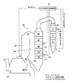
図1に示す如く、焼却炉10に連設され、排ガスから熱回収するためのボイラ20は、排ガスの流通路を屈曲せしめる2つの変向部21、22により区分され、排ガス流れ方向の上流側から、第1放射室26、第2放射室28、及び対流伝熱室30を備えている。焼却炉10から排ガスを受け入れる第1放射室26の入口近傍はガス混合室24となっている。焼却炉10から導入される排ガスは、第1放射室26の下方から上方へ、第2放射室28の上方から下方へ、対流伝熱室30の下方から上方へ流通される。
As shown in FIG. 1, a
前記第1放射室26及び第2放射室28は、排ガスからの放射熱を受けて蒸気を発生させる放射伝熱面をそれぞれ備えている。
The
前記対流伝熱室30は、排ガス流れ方向の上流側から、スクリーン管32、2次過熱器34、3次過熱器36、1次過熱器38、及び第2エコノマイザ42を備えている。2次過熱器34、3次過熱器36、1次過熱器38は、それぞれ、水平方向に配列した複数の伝熱管を高さ方向に多段に設けた伝熱管群を備え、該伝熱管群が対流伝熱面を構成しており、排ガスとの熱交換により蒸気を発生して更に過熱するようにされている。スクリーン管32には伝熱管が旗形に備えられ、対流伝熱室30に導入される排ガスを冷却するようにされている。
The convection
本発明を実施するため、本発明の第1実施形態においては、対流伝熱室30の伝熱管に付着したダストによるボイラ20の閉塞を抑制するボイラの閉塞抑制装置として、燃料ガスと酸化剤ガスを高圧下で混合し燃焼して圧力波を発生させボイラ20内へ圧力波を放出する圧力波発生装置61、62を設け、該圧力波発生装置61、62の圧力波放出ノズル(図示省略)を、前記対流伝熱室30に配設している。
In order to implement the present invention, in the first embodiment of the present invention, a fuel gas and an oxidant gas are used as a boiler blockage suppression device that suppresses blockage of the
前記圧力波発生装置61、62の圧力波放出ノズルは、前記対流伝熱室30の対流伝熱管群近傍に、例えばそれぞれ、スクリーン管32と2次過熱器34との間、及び、3次過熱器36と1次過熱器38との間に設けることができる。また、これらの位置に設けられたマンホール(図示省略)に圧力波放出ノズルを取り付けることもできる。
The pressure wave discharge nozzles of the
圧力波放出ノズルからの圧力波放出を制御するため、廃棄物焼却炉10内の圧力を測定する焼却炉内圧力計71と、ボイラ20出口の圧力を測定するボイラ出口圧力計72と、圧力波発生装置61、62の運転を制御する圧力波発生制御装置70とを備え、該圧力波発生制御装置70は、焼却炉内圧力計71による炉内圧力測定値とボイラ出口圧力計72によるボイラ出口圧力測定値との差圧値が所定値以上であるとき、圧力波放出ノズルから圧力波を放出するように圧力波発生装置61、62を制御する。
In order to control the pressure wave discharge from the pressure wave discharge nozzle, an
具体的には、圧力波発生制御装置70は、炉内圧力測定値とボイラ出口圧力測定値との差圧値が、0.1〜0.3kPaの範囲で予め定める所定値以上であるとき、圧力波を放出するように制御する。
Specifically, the pressure wave
ここで、予め定める差圧値の所定値として0.1kPa未満の差圧値とすると、ダスト付着層の形成による差圧値の増加とは異なる原因による差圧値の増加(焼却炉内の焼却状況の変動の影響など)に対しても圧力波を放出することになり、燃料ガスや酸化剤ガスの使用量が多くなり運転コストが嵩むため好ましくない。 Here, if the predetermined differential pressure value is a differential pressure value of less than 0.1 kPa, an increase in the differential pressure value due to a cause different from the increase in the differential pressure value due to the formation of the dust adhesion layer (incineration in the incinerator) The pressure wave is also released against the influence of fluctuations in the situation, etc., which is not preferable because the amount of fuel gas and oxidant gas used increases and the operating cost increases.
逆に、予め定める差圧値の所定値として0.3kPaより高い差圧値とすると、ダスト付着層の形成が進行していて、圧力波を放出しても付着ダストの剥離除去が困難であることとなり好ましくない。 On the other hand, if a predetermined pressure value of a pressure difference higher than 0.3 kPa is set as a predetermined value, a dust adhering layer is formed, and it is difficult to peel off adhering dust even if a pressure wave is released. That is not preferable.
前記圧力波発生装置61、62は、その混合ガスホルダに燃料ガス(例えばメタンガス)と酸化剤ガス(例えば酸素ガス)を高圧下で充填、混合し、前記圧力波発生制御装置70から与えられる指示により混合ガスを点火プラグで着火し、爆発燃焼させて圧力波を発生させる。爆発燃焼時の混合ガスホルダ内の圧力は例えば最高53.2barに達する。これにより、ボイラ20内の圧力波放出ノズル先端からボイラ20内部に圧力波が放出される。その際、対流伝熱管に振動及び風圧を与え、付着ダストを剥離し除去する。これにより、前記対流伝熱室30の対流伝熱面の伝熱面に付着したダストが除去される。
The
圧力波放出ノズルから放出される圧力波が、対流伝熱面に付着ダストを剥離させる程度の振動及び風圧を与える範囲は、圧力波放出ノズルから上方及び下方へそれぞれ3.5m程度の範囲である。そのため、対流伝熱室30における圧力波放出ノズルの高さ方向配設間隔を7m以下とすることが好ましく、付着ダストを剥離させる作用が及ぶ範囲を、隣接する範囲との間に隙間が生じることなく設けることができる。さらに、圧力波放出ノズルの高さ方向配設間隔を3m以上とすることが好ましく、隣接する圧力波放出ノズルから放出する圧力波同士が干渉して圧力波の作用効果が低下することなく、付着ダストを確実に剥離させることができる。このように、対流伝熱室30の伝熱管群に十分な振動と風圧を与えるためには、圧力波放出ノズルの高さ方向配設間隔を3m以上7m以下とすることが好ましい。
The range in which the pressure wave discharged from the pressure wave discharge nozzle gives vibration and wind pressure to the extent that the adhering dust is separated from the convection heat transfer surface is about 3.5 m upward and downward from the pressure wave discharge nozzle. . Therefore, it is preferable to set the height direction disposition interval of the pressure wave discharge nozzles in the convection
次に、図2に示す如く、ボイラ20の下流側に別置エコノマイザ50が付設される場合に適用した本発明の第2実施形態について説明する。
Next, a second embodiment of the present invention applied when a separate economizer 50 is attached downstream of the
本実施形態では、別置エコノマイザ50内には第1エコノマイザ51が配設され、該別置エコノマイザ50の第1エコノマイザ51と対流伝熱室30内の第2エコノマイザ42には伝熱管が配設され、排ガスとの熱交換により水が加熱され加温水が生成され、ボイラ20に供給される。
In the present embodiment, a
本実施形態においても、図2に示す如く、燃料ガスと酸化剤ガスを高圧下で混合し燃焼して圧力波を発生させボイラ20内とエコノマイザ51内へ圧力波を放出する圧力波発生装置61〜63を設け、該圧力波発生装置61〜63の圧力波放出ノズル(図示省略)を、前記対流伝熱室30と別置エコノマイザ50に配設する。
Also in the present embodiment, as shown in FIG. 2, a
そして、廃棄物焼却炉10内の圧力を測定する焼却炉内圧力計71と、エコノマイザ出口の圧力を測定するエコノマイザ出口圧力計73と、圧力波発生装置60の運転を制御する圧力波発生制御装置70とを備え、圧力波発生制御装置70は、焼却炉内圧力計71による炉内圧力測定値とエコノマイザ出口圧力計73によるエコノマイザ出口圧力測定値との差圧値が所定値以上であるとき、圧力波放出ノズルから圧力波を放出するように制御する。
An
具体的には、圧力波発生制御装置70は、炉内圧力測定値とエコノマイザ出口圧力測定値との差圧値が、0.1〜0.3kPaの範囲で予め定める所定値以上であるとき、圧力波を放出するように制御する。
Specifically, the pressure wave
ここで、予め定める差圧値の所定値として0.1kPa未満の差圧値とすると、ダスト付着層の形成による差圧値の増加とは異なる原因による差圧値の増加(焼却炉内の焼却状況の変動の影響など)に対しても圧力波を放出することになり、燃料ガスや酸化剤ガスの使用量が多くなり運転コストが嵩むため好ましくない。 Here, if the predetermined differential pressure value is a differential pressure value of less than 0.1 kPa, an increase in the differential pressure value due to a cause different from the increase in the differential pressure value due to the formation of the dust adhesion layer (incineration in the incinerator) The pressure wave is also released against the influence of fluctuations in the situation, etc., which is not preferable because the amount of fuel gas and oxidant gas used increases and the operating cost increases.
逆に、予め定める差圧値の所定値として0.3kPaより高い差圧値とすると、ダスト付着層の形成が進行していて、圧力波を放出しても付着ダストの剥離除去が困難であることとなり好ましくない。 On the other hand, if a predetermined pressure value of a pressure difference higher than 0.3 kPa is set as a predetermined value, a dust adhering layer is formed, and it is difficult to peel off adhering dust even if a pressure wave is released. That is not preferable.
本発明により、ボイラの運転中にスートブロワを運転しなくてもボイラ内壁に付着したダストを効率的に除去することが可能になり、ボイラの収熱量を維持することができる。スートブロワの運転がなくなるので、前述したドレンアタックに起因する腐食・減肉トラブルがなくなり、経済的である。また、スートブロワを用いる場合に生じる前述の問題を防ぐことができる。 According to the present invention, dust attached to the boiler inner wall can be efficiently removed without operating the soot blower during operation of the boiler, and the amount of heat collected by the boiler can be maintained. Since the operation of the soot blower is eliminated, the above-described corrosion / thinning trouble caused by the drain attack is eliminated, which is economical. In addition, the above-mentioned problems that occur when using a soot blower can be prevented.
また、スートブロワの運転は一般的に一日あたり1回あるいは2回であるのに対し、圧力波発生装置は1時間から6時間の間に1回以上運転する。つまり、短時間の間にダストを除去することになる。そうすると、付着するダスト量を低減することが可能になるので、付着したダスト中に含まれる重金属類、塩類などによるボイラ内壁面、伝熱管表面の腐食進行を防止することができ、メンテナンス費を下げ、運転管理も容易な廃棄物焼却施設ボイラ操業が可能になる。加えて必要最低限の圧力波発生装置の設置により、経済面にも有利な装置運用が可能となる。 The soot blower is generally operated once or twice per day, whereas the pressure wave generator is operated at least once in 1 to 6 hours. That is, dust is removed in a short time. As a result, the amount of dust adhering can be reduced, so that it is possible to prevent the corrosion of the boiler inner wall surface and heat transfer tube surface due to heavy metals and salts contained in the adhering dust, thereby reducing maintenance costs. This makes it possible to operate a waste incineration facility boiler that is easy to manage. In addition, the installation of the minimum necessary pressure wave generator enables the operation of the apparatus which is economically advantageous.
なお、第2実施形態では、圧力波放出ノズルを対流伝熱室30に2個、別置エコノマイザ50に少なくとも1個配設していたが、圧力波放出ノズルの配設位置及び個数はこれに限定されず、別置エコノマイザ50の圧力波放出ノズルを省略したり、対流伝熱室30に圧力波放出ノズルを1個配設することもできる。
In the second embodiment, two pressure wave discharge nozzles are disposed in the convection
又、第2放射室28に圧力波発生装置の圧力波放出ノズルまたは水噴射装置を設置して、第2放射室28内の水冷壁面(放射伝熱面)に付着したダストを除去するようにして、水冷壁での熱回収効率の低下を防止し、第2放射室28から対流伝熱室30入口部へ流入する排ガス温度が所定温度より高く上昇することを抑制することにより、排ガス中の液体状態の酸化鉛、酸化亜鉛の存在割合の増加を防ぎ、付着ダスト層の形成を抑制することもできる。
In addition, a pressure wave discharge nozzle or a water injection device of a pressure wave generator is installed in the
図3に、本発明の実施形態である対流伝熱室30内の圧力波放出ノズルの配設位置を示す。実施形態Aは、対流伝熱室30が排ガス流れ方向で上流側からスクリーン管32、2次過熱器34、3次過熱器36及び1次過熱器38を有するボイラで、前記対流伝熱室30の対流伝熱面に付着したダストによるボイラの閉塞を抑制するボイラの閉塞抑制装置において、燃料ガスと酸化剤ガスを高圧下で混合し燃焼して圧力波を発生させボイラ内へ圧力波を放出する圧力波発生装置を設け、該圧力波発生装置の圧力波放出ノズルを、前記スクリーン管32と前記2次過熱器34との間と、前記3次過熱器36と前記1次過熱器38との間に配設している。
In FIG. 3, the arrangement | positioning position of the pressure wave discharge | release nozzle in the convection
なお、実施形態A’のように、前記1次過熱器38の下流側(即ち最下流側)に第2エコノマイザ42が設けられていたり、実施形態A”のように、同じく前記1次過熱器38の下流側(即ち最下流側)に水平蒸発管44が設けられていても良い。
A
ここで、前記水平蒸発管44は、エコノマイザにより加温された水を加熱し、蒸気を発生させる伝熱管である。
Here, the
実施形態A'''は、対流伝熱室30が排ガス流れ方向で上流側からスクリーン管32、
3次過熱器36、2次過熱器34及び1次過熱器38を有するボイラ20で、圧力波発生装置の圧力波放出ノズルを、前記スクリーン管32と前記3次過熱器36との間と、前記2次過熱器34と前記1次過熱器38との間に配設している。さらに、前記1次過熱器38の下流側(即ち最下流側)に第2エコノマイザ42が設けられていたり、同じく前記1次過熱器38の下流側(即ち最下流側)に水平蒸発管44が設けられていても良い。
In the embodiment A ′ ″, the convection
In the
実施形態Bは、前記対流伝熱室30が排ガス流れ方向で上流側からスクリーン管32、水平蒸発管44、2次過熱器34、1次過熱器38及び第2エコノマイザ42を有するボイラで、前記対流伝熱室30の対流伝熱面に付着したダストによるボイラの閉塞を抑制するボイラの閉塞抑制装置において、燃料ガスと酸化剤ガスを高圧下で混合し燃焼して圧力波を発生させボイラ内へ圧力波を放出する圧力波発生装置を設け、該圧力波発生装置の圧力波放出ノズルを、前記水平蒸発管44と前記2次過熱器34との間と、前記1次過熱器38と前記第2エコノマイザ42との間に配設している。
The embodiment B is a boiler in which the convection
なお、上記実施形態A、A’、A”、A'''、Bでは、いずれも図2に示した別置エコノマイザ50が設けられ、その中に第1エコノマイザ51が設けられている。
In Embodiments A, A ′, A ″, A ′ ″, and B, the separate economizer 50 shown in FIG. 2 is provided, and the
次に、別置エコノマイザ50を設けず、対流伝熱室30内に第1エコノマイザ51及び第2エコノマイザ42を設けた実施形態B’、C、Dについて説明する。
Next, Embodiments B ′, C, and D in which the
実施形態B’では、実施形態Bと同様の構成において、対流伝熱室30内の第2エコノマイザ42の下流側(即ち最下流側)に第1エコノマイザ51が設けられており、実施形態Bと同様に、圧力波発生装置の圧力波放出ノズルを、前記水平蒸発管44と前記2次過熱器34との間と、前記1次過熱器38と前記第2エコノマイザ42との間に配設している。
In the embodiment B ′, the
又、実施形態Cは、前記対流伝熱室30が排ガス流れ方向で上流側からスクリーン管32、2次過熱器34、1次過熱器38、水平蒸発管44及び第1、第1エコノマイザ51、第2エコノマイザ42を有するボイラで、前記対流伝熱室30の対流伝熱面に付着したダストによるボイラの閉塞を抑制するボイラの閉塞抑制装置において、燃料ガスと酸化剤ガスを高圧下で混合し燃焼して圧力波を発生させボイラ内へ圧力波を放出する圧力波発生装置を設け、該圧力波発生装置の圧力波放出ノズルを、前記スクリーン管32と前記2次過熱器34との間と、前記水平蒸発管44と前記第1エコノマイザ51との間に配設している。
Further, in the embodiment C, the convection
又、実施形態Dは、前記対流伝熱室30が排ガス流れ方向で上流側からスクリーン管32、過熱器46、第1エコノマイザ51及び第2エコノマイザ42を有するボイラで、前記対流伝熱室30の対流伝熱面に付着したダストによるボイラの閉塞を抑制するボイラの閉塞抑制装置において、燃料ガスと酸化剤ガスを高圧下で混合し燃焼して圧力波を発生させボイラ内へ圧力波を放出する圧力波発生装置を設け、該圧力波発生装置の圧力波放出ノズルを、前記スクリーン管32と前記過熱器46との間と、前記第1エコノマイザ51と前記第2エコノマイザ42との間に配設している。
Embodiment D is a boiler in which the convection
実施形態A、A’、A”、A'''、Dでは、前記対流伝熱室30の過熱器へ、放射室の
放射伝熱面で加熱され発生した蒸気を供給し、蒸気を加熱して加熱蒸気とするが、実施形態B、B’、Cのように、水平蒸発管44を設ける場合は、これに加えて対流伝熱室30でも蒸気を発生させる。
In Embodiments A, A ′, A ″, A ′ ″ and D, the steam generated by heating on the radiant heat transfer surface of the radiant chamber is supplied to the superheater of the convection
なお、前記対流伝熱室30の高さは10m以上20m以下とし、前記圧力波放出ノズルの高さ方向配設間隔は3m以上7m以下とすることができる。
In addition, the height of the convection
タイヤ等の亜鉛を多く含む廃棄物と電子基板などの鉛を多く含む廃棄物とを焼却処理した場合、焼却処理開始から30日後に焼却炉内圧力が−0.1kPa、エコノマイザ出口圧力が−0.3kPaとなり、差圧が0.2kPaを超過した。そのまま焼却処理運転を継続したところ、廃棄物焼却施設内の排ガス誘引ファンが焼却炉排ガスを排出できなくなって焼却炉の緊急停止に到った。ボイラ内を点検したところ、ボイラ過熱器伝熱管はダストで覆われて排ガス流路が狭められて閉塞していた。ボイラ過熱器伝熱管の複数個所で付着ダストを採取して分析した亜鉛、鉛の含有率を表1に示す。また鉛、亜鉛をあまり含まない廃棄物を焼却する通常運転を実施した後に実施したボイラ内点検時に採取したダストの分析結果も表1に示す。 When incineration of waste containing a lot of zinc such as tires and waste containing a lot of lead such as an electronic substrate, the pressure in the incinerator is -0.1 kPa and the economizer outlet pressure is -0 after 30 days from the start of the incineration The pressure difference exceeded 0.2 kPa. When the incineration treatment operation was continued as it was, the exhaust gas induction fan in the waste incineration facility could not discharge the incinerator exhaust gas, resulting in an emergency stop of the incinerator. When the inside of the boiler was inspected, the boiler superheater heat transfer tube was covered with dust and the exhaust gas passage was narrowed and blocked. Table 1 shows the contents of zinc and lead analyzed by collecting adhering dust at multiple locations on the boiler superheater heat transfer tube. Table 1 also shows the analysis results of the dust collected during the inspection in the boiler that was conducted after the normal operation of incinerating the waste that does not contain much lead and zinc.

表1に示されるように、ボイラ閉塞が生じ焼却炉の緊急停止に到った場合には、過熱器伝熱管表面に付着したダストには亜鉛化合物、鉛化合物が多く含まれている。このことから、ボイラ過熱器伝熱管群において塩化亜鉛、塩化鉛の付着により付着ダスト層が形成されてボイラ閉塞に到ったことが確認できる。 As shown in Table 1, when the boiler is blocked and the incinerator is brought to an emergency stop, the dust adhering to the superheater heat transfer tube surface contains a large amount of zinc compounds and lead compounds. From this, it can be confirmed that in the boiler superheater heat transfer tube group, the adhering dust layer was formed by the adhesion of zinc chloride and lead chloride, and the boiler was blocked.
ボイラの対流伝熱室の過熱器伝熱管群に圧力波発生装置を設置し、焼却炉内圧力とエコノマイザ出口圧力の差圧が0.2kPaを超過した際に圧力波発生装置を運転し圧力波を放出するようにした。その結果、タイヤ等の亜鉛を多く含む廃棄物と電子基板などの鉛を多く含む廃棄物を焼却処理した場合でも、ボイラ過熱器伝熱管に付着ダスト層が形成されてボイラ閉塞することなく、安定して焼却炉施設の運転を継続することができた。 A pressure wave generator is installed in the superheater heat transfer tube group in the convection heat transfer chamber of the boiler, and the pressure wave generator operates when the differential pressure between the incinerator pressure and the economizer outlet pressure exceeds 0.2 kPa. Was released. As a result, even when waste containing a lot of zinc such as tires and waste containing a lot of lead such as electronic boards are incinerated, an adhering dust layer is formed on the boiler superheater heat transfer tube and the boiler is not clogged. As a result, the operation of the incinerator facility was continued.
なお、前記説明では、本発明を都市ごみ焼却炉に連設されたボイラに適用していたが、本発明の適用対象はこれに限定されない。 In addition, in the said description, although this invention was applied to the boiler connected with the municipal waste incinerator, the application object of this invention is not limited to this.
10…焼却炉
20…ボイラ
21、22…変向部
26…第1放射室
28…第2放射室
30…対流伝熱室
32…スクリーン管
34…2次過熱器
36…3次過熱器
38…1次過熱器
42…第2エコノマイザ
44…水平蒸発管
46…過熱器
50…別置エコノマイザ
51…第1エコノマイザ
61、62、63…圧力波発生装置
70…圧力波発生制御装置
71…焼却炉内圧力計
72…ボイラ出口圧力計
73…エコノマイザ出口圧力計
DESCRIPTION OF
Claims (8)
燃料ガスと酸化剤ガスを高圧下で混合し燃焼して圧力波を発生させボイラ内へ圧力波を放出する圧力波発生装置を設け、該圧力波発生装置の圧力波放出ノズルを、前記対流伝熱室に配設すると共に、
廃棄物焼却炉内の圧力を測定する炉内圧力計と、ボイラ出口の圧力を測定するボイラ出口圧力計と、圧力波発生装置の運転を制御する圧力波発生制御装置とを備え、
該圧力波発生制御装置は、前記炉内圧力計による炉内圧力測定値と前記ボイラ出口圧力計によるボイラ出口圧力測定値との差圧値が所定値以上であるとき、前記圧力波放出ノズルから圧力波を放出するように前記圧力波発生装置を制御することを特徴とするボイラの閉塞抑制装置。 Radiation that generates steam by receiving radiant heat from the exhaust gas from the upstream side, separated by two turning sections that bend the flow path of the exhaust gas, connected to the waste incinerator to recover heat from the exhaust gas A convection heat transfer chamber including first and second radiation chambers having heat transfer surfaces, and a convection heat transfer chamber that generates steam by heat exchange between the exhaust gas and the convection heat transfer surfaces of the heat transfer tubes, and further superheats the steam; A boiler blockage suppression device that suppresses boiler blockage due to dust adhering to the heat transfer tube of the hot chamber,
A pressure wave generator is provided that mixes fuel gas and oxidant gas under high pressure and burns to generate a pressure wave and discharge the pressure wave into the boiler. The pressure wave discharge nozzle of the pressure wave generator is connected to the convection In the heat chamber,
In-furnace pressure gauge that measures the pressure in the waste incinerator, a boiler outlet pressure gauge that measures the pressure of the boiler outlet, and a pressure wave generation control device that controls the operation of the pressure wave generation device,
When the differential pressure value between the measured pressure value in the furnace by the in-furnace pressure gauge and the measured value in the boiler outlet pressure by the boiler outlet pressure gauge is equal to or greater than a predetermined value, the pressure wave generation control device A boiler blockage suppression device, wherein the pressure wave generator is controlled to release a pressure wave.
燃料ガスと酸化剤ガスを高圧下で混合し燃焼して圧力波を発生させボイラ内とエコノマイザ内へ圧力波を放出する圧力波発生装置を設け、該圧力波発生装置の圧力波放出ノズルを、前記対流伝熱室とエコノマイザに配設すると共に、
廃棄物焼却炉内の圧力を測定する炉内圧力計と、エコノマイザ出口の圧力を測定するエコノマイザ出口圧力計と、圧力波発生装置の運転を制御する圧力波発生制御装置とを備え、
該圧力波発生制御装置は、前記炉内圧力計による炉内圧力測定値と前記エコノマイザ出口圧力計によるエコノマイザ出口圧力測定値との差圧値が所定値以上であるとき、前記圧力波放出ノズルから圧力波を放出するように前記圧力波発生装置を制御することを特徴とするボイラの閉塞抑制装置。 Radiation that generates steam by receiving radiant heat from the exhaust gas from the upstream side, separated by two turning sections that bend the flow path of the exhaust gas, connected to the waste incinerator to recover heat from the exhaust gas First and second radiation chambers having a heat transfer surface, a convection heat transfer chamber that generates steam by heat exchange between the exhaust gas and the convection heat transfer surface of the heat transfer tube, and further superheats, and a convection transfer between the exhaust gas and the heat transfer tube A boiler equipped with an economizer that heats water supplied to the boiler by heat exchange with the hot surface, and a boiler blockage suppression device that suppresses blockage of the boiler and economizer due to dust adhering to the convection heat transfer chamber and the heat transfer pipe of the economizer There,
A pressure wave generator is provided that mixes and burns fuel gas and oxidant gas under high pressure to generate pressure waves and discharges pressure waves into the boiler and the economizer, and a pressure wave discharge nozzle of the pressure wave generator is provided. While arranged in the convection heat transfer chamber and economizer,
An in-furnace pressure gauge that measures the pressure in the waste incinerator, an economizer outlet pressure gauge that measures the pressure of the economizer outlet, and a pressure wave generation control device that controls the operation of the pressure wave generator,
When the differential pressure value between the measured pressure value in the furnace by the pressure gauge in the furnace and the measured pressure value in the economizer outlet by the economizer outlet pressure gauge is equal to or greater than a predetermined value, the pressure wave generation control device A boiler blockage suppression device, wherein the pressure wave generator is controlled to release a pressure wave.
燃料ガスと酸化剤ガスを高圧下で混合し燃焼して圧力波を発生させ、前記対流伝熱室に配設された圧力波放出ノズルからボイラ内へ圧力波を放出する圧力波発生装置の運転を制御する圧力波発生制御装置を用いて、
炉内圧力計により測定する廃棄物焼却炉の炉内圧力測定値と、ボイラ出口圧力計により測定するボイラ出口圧力測定値との差圧値が所定圧力以上であるとき、前記圧力波放出ノズルから圧力波を放出するように前記圧力波発生装置を制御することを特徴とするボイラの閉塞抑制方法。 Radiation that generates steam by receiving radiant heat from the exhaust gas from the upstream side, separated by two turning sections that bend the flow path of the exhaust gas, connected to the waste incinerator to recover heat from the exhaust gas A convection heat transfer chamber including first and second radiation chambers having heat transfer surfaces, and a convection heat transfer chamber that generates steam by heat exchange between the exhaust gas and the convection heat transfer surfaces of the heat transfer tubes, and further superheats the steam; A boiler blockage suppression method that suppresses blockage of a boiler due to dust adhering to a heat transfer tube of a hot chamber,
Operation of a pressure wave generator that mixes fuel gas and oxidant gas under high pressure and burns them to generate pressure waves, and discharges pressure waves into the boiler from the pressure wave discharge nozzles disposed in the convection heat transfer chamber Using a pressure wave generation control device that controls
When the pressure difference between the pressure value measured in the furnace of the waste incinerator measured by the pressure gauge inside the furnace and the pressure measured from the boiler outlet pressure measured by the boiler outlet pressure gauge is equal to or higher than a predetermined pressure, the pressure wave discharge nozzle A method for suppressing the blockage of a boiler, wherein the pressure wave generator is controlled to release a pressure wave.
燃料ガスと酸化剤ガスを高圧下で混合し燃焼して圧力波を発生させ、前記対流伝熱室とエコノマイザに配設された圧力波放出ノズルからボイラ内とエコノマイザ内へ圧力波を放出する圧力波発生装置の運転を制御する圧力波発生制御装置を用いて、
炉内圧力計により測定する廃棄物焼却炉の炉内圧力測定値と、エコノマイザ出口圧力計により測定するエコノマイザ出口圧力測定値との差圧値が所定圧力以上であるとき、前記圧力波放出ノズルから圧力波を放出するように前記圧力波発生装置を制御することを特徴とするボイラの閉塞抑制方法。 Radiation that generates steam by receiving radiant heat from the exhaust gas from the upstream side, separated by two turning sections that bend the flow path of the exhaust gas, connected to the waste incinerator to recover heat from the exhaust gas First and second radiation chambers having a heat transfer surface, a convection heat transfer chamber that generates steam by heat exchange between the exhaust gas and the convection heat transfer surface of the heat transfer tube, and further superheats, and a convection transfer between the exhaust gas and the heat transfer tube A boiler comprising an economizer that heats water supplied to a boiler by heat exchange with a hot surface, wherein the boiler is blocked by a dust that adheres to the convection heat transfer chamber and the heat transfer pipe of the economizer and prevents the boiler from being blocked. ,
Fuel gas and oxidant gas are mixed and burned under high pressure to generate pressure waves, and pressure waves are released from the pressure wave discharge nozzles disposed in the convection heat transfer chamber and economizer into the boiler and economizer. Using a pressure wave generation control device that controls the operation of the wave generation device,
When the pressure difference between the measured value in the furnace of the waste incinerator measured by the pressure gauge in the furnace and the measured value of the economizer outlet pressure measured by the economizer outlet pressure gauge is equal to or higher than a predetermined pressure, the pressure wave discharge nozzle A method for suppressing the blockage of a boiler, wherein the pressure wave generator is controlled to release a pressure wave.
Priority Applications (1)
| Application Number | Priority Date | Filing Date | Title |
|---|---|---|---|
| JP2016073483A JP2017181007A (en) | 2016-03-31 | 2016-03-31 | Blockage suppression device and blockage suppression method for boiler |
Applications Claiming Priority (1)
| Application Number | Priority Date | Filing Date | Title |
|---|---|---|---|
| JP2016073483A JP2017181007A (en) | 2016-03-31 | 2016-03-31 | Blockage suppression device and blockage suppression method for boiler |
Publications (1)
| Publication Number | Publication Date |
|---|---|
| JP2017181007A true JP2017181007A (en) | 2017-10-05 |
Family
ID=60006743
Family Applications (1)
| Application Number | Title | Priority Date | Filing Date |
|---|---|---|---|
| JP2016073483A Pending JP2017181007A (en) | 2016-03-31 | 2016-03-31 | Blockage suppression device and blockage suppression method for boiler |
Country Status (1)
| Country | Link |
|---|---|
| JP (1) | JP2017181007A (en) |
Cited By (6)
| Publication number | Priority date | Publication date | Assignee | Title |
|---|---|---|---|---|
| JP2017187267A (en) * | 2016-03-31 | 2017-10-12 | Jfeエンジニアリング株式会社 | Boiler anticorrosive device and anticorrosive method |
| CN109899776A (en) * | 2019-03-14 | 2019-06-18 | 上海外高桥造船有限公司 | Tripping in formula exhaust boiler lower smoke box |
| JP6761558B1 (en) * | 2020-06-03 | 2020-09-23 | 三菱重工環境・化学エンジニアリング株式会社 | Boiler tube group adhering ash removal system |
| CN111998384A (en) * | 2020-08-27 | 2020-11-27 | 广州龙鑫蓄热工业炉有限公司 | Automatic timing adjusting method for heat accumulating type burner |
| JP2021042870A (en) * | 2019-09-06 | 2021-03-18 | 三菱重工環境・化学エンジニアリング株式会社 | System of removing ash deposited on boiler pipe groups |
| CN114165791A (en) * | 2021-06-22 | 2022-03-11 | 中晟工程技术(天津)有限公司 | Cooler of dangerous waste incinerator |
-
2016
- 2016-03-31 JP JP2016073483A patent/JP2017181007A/en active Pending
Cited By (8)
| Publication number | Priority date | Publication date | Assignee | Title |
|---|---|---|---|---|
| JP2017187267A (en) * | 2016-03-31 | 2017-10-12 | Jfeエンジニアリング株式会社 | Boiler anticorrosive device and anticorrosive method |
| CN109899776A (en) * | 2019-03-14 | 2019-06-18 | 上海外高桥造船有限公司 | Tripping in formula exhaust boiler lower smoke box |
| JP2021042870A (en) * | 2019-09-06 | 2021-03-18 | 三菱重工環境・化学エンジニアリング株式会社 | System of removing ash deposited on boiler pipe groups |
| JP6761558B1 (en) * | 2020-06-03 | 2020-09-23 | 三菱重工環境・化学エンジニアリング株式会社 | Boiler tube group adhering ash removal system |
| JP2021188859A (en) * | 2020-06-03 | 2021-12-13 | 三菱重工環境・化学エンジニアリング株式会社 | Boiler pipe group adhesion ash removal system |
| KR20230009953A (en) | 2020-06-03 | 2023-01-17 | 미츠비시 쥬코 칸쿄 카가쿠 엔지니어링 가부시키가이샤 | Boiler pipe group adhesive removal system |
| CN111998384A (en) * | 2020-08-27 | 2020-11-27 | 广州龙鑫蓄热工业炉有限公司 | Automatic timing adjusting method for heat accumulating type burner |
| CN114165791A (en) * | 2021-06-22 | 2022-03-11 | 中晟工程技术(天津)有限公司 | Cooler of dangerous waste incinerator |
Similar Documents
| Publication | Publication Date | Title |
|---|---|---|
| JP2017181007A (en) | Blockage suppression device and blockage suppression method for boiler | |
| JP2017187267A (en) | Boiler anticorrosive device and anticorrosive method | |
| KR910003267B1 (en) | Single drum all-welded boiler | |
| JP6693239B2 (en) | Boiler dust removing device and dust removing method | |
| CN105953231B (en) | A kind of high parameter garbage burning boiler with reheating | |
| JP5150500B2 (en) | Steam generating boiler from flue gas under optimum conditions | |
| JP5971438B1 (en) | Boiler dust removing device and dust removing method | |
| JP7153431B2 (en) | Boiler corrosion prevention device and corrosion prevention method | |
| JP6309709B2 (en) | BOILER WITH CORROSION CONTROL DEVICE AND BOILER CORROSION CONTROL METHOD | |
| JP6863257B2 (en) | Waste incinerator Boiler blockage and corrosion control methods | |
| JP2019105394A (en) | Method for suppressing blockage and corrosion in waste incinerator boiler | |
| JP2013124568A (en) | Waste power generation system | |
| JP2019045104A (en) | Waste incinerator boiler | |
| JP2016041939A (en) | Waste power generation system | |
| JP2019158167A (en) | Corrosion prevention metho on radiant heat transfer surface of boiler, and boiler | |
| CN104949131A (en) | Biomass garbage combustion system and method | |
| JP2007309162A (en) | Waste incinerator power generation device | |
| CN112880204B (en) | Method for protecting smoke side smoke screen of boiler | |
| JP2018173061A (en) | Power generation system and power generation method | |
| JP6927705B2 (en) | Methods and equipment for producing superheated steam by the heat generated in the boiler of the incinerator | |
| JP2005315440A (en) | Cooling device, cooling method and heat recovering device | |
| CN213066123U (en) | Circulating fluidized bed incineration boiler for burning solid wastes | |
| JP5144447B2 (en) | Boiler equipment | |
| JP2005164117A (en) | Combustion air preheating method for melting furnace and its device | |
| JP2005207697A (en) | Exhaust gas treatment method and device for fusion furnace |
Legal Events
| Date | Code | Title | Description |
|---|---|---|---|
| A621 | Written request for application examination |
Free format text: JAPANESE INTERMEDIATE CODE: A621 Effective date: 20180807 |
|
| A977 | Report on retrieval |
Free format text: JAPANESE INTERMEDIATE CODE: A971007 Effective date: 20190610 |
|
| A131 | Notification of reasons for refusal |
Free format text: JAPANESE INTERMEDIATE CODE: A131 Effective date: 20190625 |
|
| A02 | Decision of refusal |
Free format text: JAPANESE INTERMEDIATE CODE: A02 Effective date: 20200107 |