JP2017166320A - Wear assembly for excavating equipment - Google Patents
Wear assembly for excavating equipment Download PDFInfo
- Publication number
- JP2017166320A JP2017166320A JP2017108914A JP2017108914A JP2017166320A JP 2017166320 A JP2017166320 A JP 2017166320A JP 2017108914 A JP2017108914 A JP 2017108914A JP 2017108914 A JP2017108914 A JP 2017108914A JP 2017166320 A JP2017166320 A JP 2017166320A
- Authority
- JP
- Japan
- Prior art keywords
- wear member
- lock
- wear
- socket
- longitudinal axis
- Prior art date
- Legal status (The legal status is an assumption and is not a legal conclusion. Google has not performed a legal analysis and makes no representation as to the accuracy of the status listed.)
- Granted
Links
Images
Classifications
-
- E—FIXED CONSTRUCTIONS
- E02—HYDRAULIC ENGINEERING; FOUNDATIONS; SOIL SHIFTING
- E02F—DREDGING; SOIL-SHIFTING
- E02F3/00—Dredgers; Soil-shifting machines
- E02F3/04—Dredgers; Soil-shifting machines mechanically-driven
- E02F3/88—Dredgers; Soil-shifting machines mechanically-driven with arrangements acting by a sucking or forcing effect, e.g. suction dredgers
- E02F3/90—Component parts, e.g. arrangement or adaptation of pumps
- E02F3/92—Digging elements, e.g. suction heads
- E02F3/9212—Mechanical digging means, e.g. suction wheels, i.e. wheel with a suction inlet attached behind the wheel
- E02F3/9225—Mechanical digging means, e.g. suction wheels, i.e. wheel with a suction inlet attached behind the wheel with rotating cutting elements
-
- E—FIXED CONSTRUCTIONS
- E02—HYDRAULIC ENGINEERING; FOUNDATIONS; SOIL SHIFTING
- E02F—DREDGING; SOIL-SHIFTING
- E02F3/00—Dredgers; Soil-shifting machines
- E02F3/04—Dredgers; Soil-shifting machines mechanically-driven
- E02F3/96—Dredgers; Soil-shifting machines mechanically-driven with arrangements for alternate or simultaneous use of different digging elements
- E02F3/961—Dredgers; Soil-shifting machines mechanically-driven with arrangements for alternate or simultaneous use of different digging elements with several digging elements or tools mounted on one machine
-
- E—FIXED CONSTRUCTIONS
- E02—HYDRAULIC ENGINEERING; FOUNDATIONS; SOIL SHIFTING
- E02F—DREDGING; SOIL-SHIFTING
- E02F9/00—Component parts of dredgers or soil-shifting machines, not restricted to one of the kinds covered by groups E02F3/00 - E02F7/00
- E02F9/28—Small metalwork for digging elements, e.g. teeth scraper bits
- E02F9/2808—Teeth
- E02F9/2816—Mountings therefor
- E02F9/2833—Retaining means, e.g. pins
- E02F9/2841—Retaining means, e.g. pins resilient
-
- E—FIXED CONSTRUCTIONS
- E02—HYDRAULIC ENGINEERING; FOUNDATIONS; SOIL SHIFTING
- E02F—DREDGING; SOIL-SHIFTING
- E02F9/00—Component parts of dredgers or soil-shifting machines, not restricted to one of the kinds covered by groups E02F3/00 - E02F7/00
- E02F9/28—Small metalwork for digging elements, e.g. teeth scraper bits
- E02F9/2808—Teeth
- E02F9/2858—Teeth characterised by shape
-
- E—FIXED CONSTRUCTIONS
- E02—HYDRAULIC ENGINEERING; FOUNDATIONS; SOIL SHIFTING
- E02F—DREDGING; SOIL-SHIFTING
- E02F9/00—Component parts of dredgers or soil-shifting machines, not restricted to one of the kinds covered by groups E02F3/00 - E02F7/00
- E02F9/28—Small metalwork for digging elements, e.g. teeth scraper bits
- E02F9/2866—Small metalwork for digging elements, e.g. teeth scraper bits for rotating digging elements
-
- E—FIXED CONSTRUCTIONS
- E02—HYDRAULIC ENGINEERING; FOUNDATIONS; SOIL SHIFTING
- E02F—DREDGING; SOIL-SHIFTING
- E02F9/00—Component parts of dredgers or soil-shifting machines, not restricted to one of the kinds covered by groups E02F3/00 - E02F7/00
- E02F9/28—Small metalwork for digging elements, e.g. teeth scraper bits
- E02F9/2883—Wear elements for buckets or implements in general
Landscapes
- Engineering & Computer Science (AREA)
- Mining & Mineral Resources (AREA)
- Civil Engineering (AREA)
- General Engineering & Computer Science (AREA)
- Structural Engineering (AREA)
- Mechanical Engineering (AREA)
- Component Parts Of Construction Machinery (AREA)
- Earth Drilling (AREA)
- Bending Of Plates, Rods, And Pipes (AREA)
- Forging (AREA)
- Organic Low-Molecular-Weight Compounds And Preparation Thereof (AREA)
- Finish Polishing, Edge Sharpening, And Grinding By Specific Grinding Devices (AREA)
- Rolls And Other Rotary Bodies (AREA)
- Mechanical Operated Clutches (AREA)
- Braking Arrangements (AREA)
- Grinding-Machine Dressing And Accessory Apparatuses (AREA)
- Clamps And Clips (AREA)
- Shovels (AREA)
Abstract
Description
本発明は、磨耗部材を掘削装置に固定するための磨耗アッセンブリに関し、特に、浚渫カッターヘッドへの取り付け及び浚渫カッターヘッドでの使用に非常に適した磨耗アッセンブリに関する。 The present invention relates to a wear assembly for securing a wear member to an excavator, and more particularly to a wear assembly that is very suitable for attachment to and use in a dredge cutterhead.
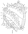
浚渫カッターヘッドは、河床などの水中にある土成分を掘削するために使用される。一般に、浚渫カッターヘッド1は、ベースリング3からハブ4に前方に伸びる複数のアーム2を含む(図21)。複数のアームは、ベースリングの周囲を離間配置され、カッターヘッドの中央軸線を中心とした広いらせん状に形成されている。各アーム2は、地面の中に掘削するための一連の離間配置された歯5が提供されている。歯は、アームに固定されたアダプター叉はベース6と、ロック8によってベースに着脱可能に取り付けられたポイント7で構成される。
The dredge cutter head is used to excavate soil components in the water such as river beds. Generally, the scissor cutter head 1 includes a plurality of
使用中、カッターヘッドは、土成分を掘削するためにその中央軸線を中心に回転される。浚渫物を取り除くために、吸引パイプがリング近傍に提供される。地面の所望の区画を掘削するために、カッターヘッドは、横方向及び前方に移動される。水の増量や水の他の運動のため、カッターヘッドは、上下に移動しがちであり、定期的に底面に衝突する。さらに、オペレータが水に下面にある掘削される地面を見ることができないことによって問題点が生じる。すなわち、最も多い他の掘削動作とは異なり、浚渫カッターヘッドは、掘削される土地に最も適合させるために路に沿って効果的に案内されることができない。重い荷重や厳しい環境にかんがみて、ポイントとベースの相互連結は、しっかりと固定される必要がある。 In use, the cutter head is rotated about its central axis to excavate soil components. A suction pipe is provided in the vicinity of the ring to remove the debris. In order to excavate the desired section of the ground, the cutter head is moved laterally and forward. The cutter head tends to move up and down due to increased water volume and other movements of the water, and regularly collides with the bottom surface. In addition, problems arise due to the operator's inability to see the excavated ground under the water. That is, unlike most other excavation operations, the dredge cutterhead cannot be effectively guided along the road to best fit the land being excavated. In view of heavy loads and harsh environments, the point and base interconnections need to be securely fastened.
歯が高速で地面の中に及び地面中を駆動されるようにカッターヘッドは回転される。従って、特に岩を掘削する際に、大きな駆動力がカッターヘッドを回転させるために必要とされる。動力条件を最小にしようと努力して、浚渫ポイントは、一般的に、地面への容易な進入のために細長くてスレンダーなビットが提供される。しかしながら、ビットが磨耗のせいで短くなると、ポイントの取り付け区分は、切断動作中に地面と係合し始める。取り付け区分は、ビットよりも幅が広く、抵抗を小さくした形状ではない。生じた抵抗の増加のため、取り付け区分は、カッターヘッドに押し付けられ、ポイントは、ビットが完全に磨耗される前に通常同時に変化される。 The cutter head is rotated so that the teeth are driven into and through the ground at high speed. Therefore, a large driving force is required to rotate the cutter head, especially when excavating rocks. In an effort to minimize power requirements, dredging points are generally provided with slender and slender bits for easy entry into the ground. However, as the bit shortens due to wear, the point attachment section begins to engage the ground during the cutting operation. The attachment section is wider than the bit and does not have a reduced resistance. Due to the increase in resistance that occurs, the mounting section is pressed against the cutter head and the points are usually changed simultaneously before the bit is completely worn.
本発明の一つの態様によれば、掘削装置のための磨耗部材は、掘削作業と関連した抵抗を最小にするため及び掘削装置を駆動するのに必要な駆動源を最小にするために、作用部分及び取り付け部分の面の軽減で形成される。低減された駆動源の消費は、より十分なオペレーション及び磨耗部材のより長い使用寿命に導く。 In accordance with one aspect of the present invention, the wear member for the drilling rig acts to minimize the resistance associated with the drilling operation and to minimize the drive source required to drive the drilling rig. Formed by reducing the surface of the part and the mounting part. Reduced drive source consumption leads to better operation and longer service life of the wear member.
本発明によれば、前面の幅は対応する後面の幅よりも大きい横断形状を有し、磨耗部材の側壁は、抵抗を低減するために前面の影にならう。この小さい後面の使用は、作用端部だけでなく、取り付け端部の少なくとも一部分にも提供される。その結果、本発明の磨耗した磨耗部材によって生じた抵抗は、従来の磨耗部材の抵抗よりも小さい。小さな抵抗は、小さな駆動消費になり、取り替えられる必要がある前の磨耗部材の使用を長くする。従って、磨耗部材の作用端部は交換が必要とされる前にさらに磨耗されることができる。 According to the present invention, the width of the front surface has a transverse shape that is greater than the width of the corresponding rear surface, and the sidewalls of the wear member follow the front surface to reduce resistance. This use of a small rear surface is provided not only on the working end but also on at least a portion of the mounting end. As a result, the resistance produced by the worn wear member of the present invention is less than that of a conventional wear member. Small resistance results in low drive consumption and lengthens the use of wear members before they need to be replaced. Thus, the working end of the wear member can be further worn before replacement is required.
本発明の他の態様によれば、磨耗部材は、ある掘削路でかつ地面中の運動方向で地面に進入する磨耗部材の部分の横断形状によって画定される掘削輪郭を有する。本発明の他の態様では、磨耗部材の面の軽減は、掘削作業中に生じた抵抗を小さくするために掘削輪郭に提供される。好適実施例では、面の軽減は、磨耗部材の寿命を通じて予期される各掘削輪郭に提供され、取り付け部分を取り囲むものを含む。 According to another aspect of the invention, the wear member has a drilling profile defined by a transverse shape of a portion of the wear member that enters the ground in a certain excavation path and in the direction of motion in the ground. In another aspect of the present invention, wear member face reduction is provided to the drilling profile to reduce the resistance created during the drilling operation. In the preferred embodiment, surface relief is provided for each excavation profile expected throughout the life of the wear member, including those surrounding the attachment portion.
本発明の他の態様によれば、磨耗部材は、掘削装置に固定されたベースのノーズを受け入れるためのソケットを含む。ソケットは、磨耗部材の台形横断の外面に概ね対応する概ね台形横断形状で形成される。この取り付け部分の外面に対するソケットの全面的な接面は、製造を容易にし、ノーズのサイズを最小にし、重量比率に対する強度を高める。 In accordance with another aspect of the invention, the wear member includes a socket for receiving a base nose secured to the excavator. The socket is formed in a generally trapezoidal transverse shape that generally corresponds to the trapezoidal transverse outer surface of the wear member. The full contact surface of the socket to the outer surface of this mounting portion facilitates manufacturing, minimizes the size of the nose, and increases strength to weight ratio.
好適な構成では、台形形状のノーズの上面、下面叉は側面の一つ以上及び対応するソケットの壁は、互いに合致するようにそれぞれ曲げられている。これらの面及び壁は、漸進的な湾曲を有し、取り付けを容易にし、磨耗部材の安定(性)を高め、使用中の縦軸線を中心とした磨耗部材の回転に抵抗する。 In a preferred configuration, one or more of the upper, lower or side surfaces of the trapezoidal nose and the corresponding socket walls are each bent to mate with each other. These surfaces and walls have a gradual curvature, facilitating installation, increasing wear member stability and resisting rotation of the wear member about the longitudinal axis during use.
本発明の他の態様によれば、ソケット及びノーズは、それぞれ、磨耗部材の縦軸線に実質的に平行に伸び、かつ、全ての方向にかかる後方への圧力に抵抗するためにソケットの周囲及びノーズの周りに実質的に伸びる後安定化面を含む。 In accordance with another aspect of the present invention, the socket and nose each extend substantially parallel to the longitudinal axis of the wear member and surround the socket to resist rearward pressure in all directions and It includes a post-stabilization surface that extends substantially around the nose.
本発明の他の態様によれば、ソケット及びノーズは、構成要素のひずみを小さくすると共に磨耗部材とノーズとの間に生じるガタガタな動きをより制御するために実質的に半球状である相補的な前支持面で形成される。 According to another aspect of the invention, the socket and nose are substantially hemispherical complementary to reduce component distortion and to more control the rattle movement that occurs between the wear member and the nose. It is formed with a front support surface.
本発明の他の態様によれば、ソケット及びノーズは、それらの前端部において湾曲した前支持面で、かつ、安定(性)を改善し、製造を容易にし、ノーズのサイズを最小にし、抵抗、ひずみ、磨耗を低減し、重量比率に対する強度を高めるために前端部の後方に概ね台形横断形状で、形成される。 In accordance with another aspect of the present invention, the socket and nose are front support surfaces that are curved at their front ends and improve stability, ease of manufacture, minimize nose size, and resistance. Formed in a generally trapezoidal transverse shape behind the front end to reduce strain, wear and increase strength to weight ratio.
本発明の他の態様によれば、磨耗アッセンブリは、ベースと、ベースに取り付ける磨耗部材と、安全で容易に使用でき容易に製造できベースへの磨耗部材の嵌合を締結できる、圧縮状態で磨耗部材をベースに保持する軸方向に配向されたロックとを含む。好適実施例では、磨耗アッセンブリは、調整可能な軸状のロックを含む。 In accordance with another aspect of the invention, the wear assembly wears in a compressed state, with a base, a wear member attached to the base, and a safe, easy to use, easily manufactured, and fastened fit of the wear member to the base. And an axially oriented lock that holds the member to the base. In the preferred embodiment, the wear assembly includes an adjustable shaft lock.
本発明の他の態様によれば、磨耗部材は、ロックが受け入れられる開口と、ロックを安定にし、ロックの締結を容易にするロックの通路に適応する開口の後壁に形成された穴とを含む。 In accordance with another aspect of the invention, the wear member includes an opening in which the lock is received and a hole formed in the rear wall of the opening that accommodates the lock passage that stabilizes the lock and facilitates locking. Including.
本発明の他の態様によれば、ベースは、単に突出したストップの使用でロックと相互作用する。その結果、ロックを受け入れるために典型的に提供されるようにノーズに穴、凹部叉は通路を必要としない。従って、ノーズの強度が高められる。 According to another aspect of the invention, the base interacts with the lock simply by the use of a protruding stop. As a result, no holes, recesses or passages are required in the nose as is typically provided for receiving locks. Accordingly, the strength of the nose is increased.
本発明の他の態様によれば、磨耗部材をロックに固定するためのロック構成は、ベース及び/叉は磨耗部材に存在するかもしれない磨耗量に関係なく予め決められた締結力を磨耗部材に安定してかけるために調整されることができる。 In accordance with another aspect of the present invention, the locking arrangement for securing the wear member to the lock provides a predetermined fastening force regardless of the amount of wear that may be present on the base and / or the wear member. Can be adjusted to hang stably.
本発明の他の態様によれば、磨耗部材は、ロックが適当に締結されたときを確認するのに使用されることができるマーカーを含む。
本発明の他の態様によれば、軸状のロックを含む使用が容易で新規なプロセスを通じて
磨耗部材はベースに取り付けられて固定される。磨耗部材は、掘削装置に固定されたベースのノーズに嵌合する。ベースは、ノーズから外方に突出するストップを含む。軸状のロックは、磨耗部材の開口の中に受け入れられ、ストップと磨耗部材の支持面との間に伸びて磨耗部材をノーズに着脱可能に保持する。
In accordance with another aspect of the invention, the wear member includes a marker that can be used to confirm when the lock is properly tightened.
In accordance with another aspect of the present invention, the wear member is attached and secured to the base through a novel process that is easy to use and includes an axial lock. The wear member fits into a base nose fixed to the excavator. The base includes a stop that projects outward from the nose. A shaft-like lock is received in the opening of the wear member and extends between the stop and the support surface of the wear member to releasably hold the wear member to the nose.
本発明の他の態様によれば、磨耗部材は、最初に掘削装置に固定されたベース上を摺動される。軸方向に配向されたロックは、ロックが軸方向に圧縮されるように、ベースのストップに抗した支持面と、磨耗部材の支持壁に抗した他の支持面とに配置される。ロックは、磨耗部材をベースに対してぴったりに動かすように調整される。 According to another aspect of the invention, the wear member is slid over a base that is initially secured to the excavator. An axially oriented lock is placed on the support surface against the base stop and the other support surface against the wear member support wall so that the lock is axially compressed. The lock is adjusted to move the wear member snugly with respect to the base.
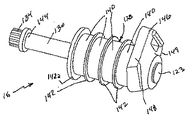
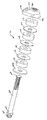
本発明の他の態様によれば、磨耗部材をベースに着脱可能に保持するロックは、支持端部及びツールと係合する端部とを有する直線状の螺子付シャフトと、螺子付シャフトに螺合されるナットと、交互に配置されると共に、支持端部とナットの間でシャフトを中心にして嵌合した、複数の環状のエラストマーディスク及び環状のスペーサを含むスプリングとを含む。 According to another aspect of the present invention, a lock for detachably holding a wear member on a base includes a linear threaded shaft having a support end and an end engaged with a tool, and a screw on the threaded shaft. And a plurality of annular elastomeric disks and springs including annular spacers that are interleaved and fitted about the shaft between the support end and the nut.
本発明は、掘削装置のための磨耗アッセンブリ10に関し、特に、浚渫作業に非常に適する。このアプリケーションでは、本発明は、浚渫カッターヘッドに取り付けるために適合された浚渫歯の用語で記載される。それにもかかわらず、本発明の様々な形態が、他の種類の磨耗アッセンブリ(例えばシュラウド)に関連して、及び他の種類の掘削装置(例えばバケット)に対して、使用されることができる。
The present invention relates to a
そのアッセンブリは、時々、上の、下の、水平の、垂直の、前方の、後方の、などの相対語で記載され、そのような用語は、本質的要素を考慮されず、単に記載を容易にするために提供される。掘削作業、特に浚渫作業での磨耗部材の方位は、著しく変更できる。これらの相対語は、別に述べられない限り、図1に示された磨耗アッセンブリ10の方位に関して理解されるべきである。
The assembly is sometimes described in relative terms such as top, bottom, horizontal, vertical, forward, backward, etc., such terms do not take into account essential elements and are simply easy to describe Provided to be. The orientation of the wear member during excavation work, particularly dredging work, can be significantly changed. These relative terms should be understood with respect to the orientation of the
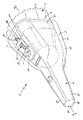
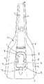
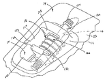
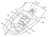
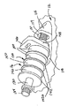
磨耗アッセンブリ10は、浚渫カッターヘッドに固定されたベース12と、磨耗部材14と、磨耗部材をベースに着脱可能に保持するロック16とを含む(図1乃至図10)。
ベース12は、その上に磨耗部材14が取り付けられる前方に突出するノーズ18と、浚渫カッターヘッドのアームに固定される取り付け端部(図示せず)を含む(図1乃至図9及び図11乃至図14)。ベースは、アームの部分として与えられ、アームに溶接され、あるいは機械的手段によって取り付けられることができる。単なる例として、米国特許第4470210号叉は米国特許第6729052号に開示されたなどのカッターヘッドに形成されかつ取り付けられることができる。
The
The
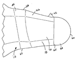
浚渫歯では、磨耗部材14は、細長いスレンダービットの形態の作用(working)部分
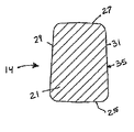
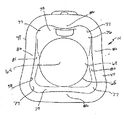
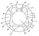
21と、ノーズ18を受け入れるためのソケット20を画定する取り付け部分23とが提供されたポイントである(図1乃至図10)。ポイント14は、それが各掘削路と概ね同じ方向に地面とかみ合うようにカッターヘッドによって回転される。その結果、ポイント14は、前面(a leading side)25と後面(a trailing side)27を含む。前面25
は、カッターヘッドの各回転で地面と最初にかみ合い、地面の貫通を案内する。本発明では、後面27は、ビット21(図5)を通じた(すなわちポイント14の縦軸線28に垂直な面に沿って)前面25と同じ幅と、少なくとも部分的に貫通した取り付け部分23(図4)とを有する。好適実施態様では、後面27は、ポイント14の長さの全体にわたって前面25よりも小さい幅を有する(図4、5及び7)。
In the toothed teeth, the
Engages the ground first with each rotation of the cutter head and guides the penetration of the ground. In the present invention, the
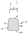
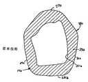
好ましくは、ポイント14のビット21は、前面25が後面27よりも広い概ね台形の横断面形状を有する(図5)。用語“横断面形状”は、磨耗部材14の縦軸線28に垂直な平面に沿った二次元の形状を呼ぶのに使用される。ポイントが細いために、側壁29、31は、掘削中前面25の影にならい、それによって、切断作業中にわずかな抵抗を生じる。好適な構成では、側壁29、31は、約16度の角度θで後面27の方に互いに近寄る(図5)が、他の角度の形状が可能である。前面25、後面27及び側壁29、31は、平らに、湾曲に、あるいは不均整にすることができる。さらに、台形以外の形状が使用されることができ、面の軽減(side relief)を提供する。
Preferably, the
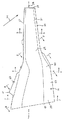
使用中、浚渫ポイント14は、各掘削路で(すなわちカッターヘッドの各回転で)特定の深さまで地面を貫通する。ポイントの長い有効耐用期間中、ビットのみが地面を貫通する。一例として、ある掘削サイクルの地面のレベルは、掘削路の中央ポイントで線3−3(図2)に沿って概ね伸びる。ビットだけが地面を貫通し、そのビットは比較的薄いので、掘削作業でかけられた抵抗は、適度の限界内にある。それにもかかわらず、高速で地面中を常に駆動される多くの歯に関し、動力要件は、常に高く、そして特に岩盤を掘削するときに作業にビットが有益であっても抵抗を減少する。
In use, the dredge
好適な構成では、側壁29、31は、後面27の方に互いに近寄るだけでなく、その側壁が掘削輪郭で前面25の影内に存在するように形状付けられる。“掘削輪郭”は、(i)地面中の掘削路の中心ポイントで移動34の方向に平らで(ii)縦軸線に対して横方向に垂直な、平面に沿って地面を貫通するポイント14の部分の横断面形状を意味するのに使用される。掘削輪郭は、実際の横断面よりも、使用中にポイントにかけられる抵抗の良い表示である。掘削輪郭の面の軽減の提供は、側壁が後面の方に互いに近寄る角度及び
ポイントの軸方向のスロープ叉は拡張部が後方に表面をつける角度に依存する。本発明は、掘削輪郭の全体像から考えられる場合に前面から後面に概ね狭まる幅を提供することである。好ましくは、掘削輪郭の面の軽減は、予期されるカッターヘッドの掘削角度を横切って伸びるが、このような面の軽減が少なくとも一つの掘削角度に存在する場合には利益がさらに得られることができる。単に一例として、図3に図示された横断面形状は、地面中を駆動されるポイント14の一部分に対する一つの掘削輪郭を表す。見られるように、ビット21は、抵抗を減少させるために側壁29、31が後面27の方に互いに近寄るような掘削輪郭でも面の軽減がさらに提供される。
In a preferred configuration, the
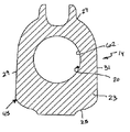
ビット21がどんどん磨耗すると、地面のレベルはだんだんと後方に漸動し、各掘削サイクルでポイント14の厚みのある部分が地面中をさらに後方に押される。従って、ポイントが磨耗するにつれてカッターヘッドを駆動するのにより大きな動力が必要とされる。結局、ポイント14の取り付け部分23が各掘削路で地面中を駆動されるほどビットは十分にどんどん磨耗する。本発明では、取り付け部分23は、取り付け部分の少なくとも前端部40(図4)、好ましくは取り付け部分の全体(図4及び図7)にわたっての面の軽減を含み続ける。図4に見られるように、取り付け部分23は、ソケット20へのノーズ18の受け入れに対応するために及びポイント14とベース12との間の相互連結のための十分な強度を提供するために、ビット21よりも大きい。側壁29、31は、後面27の方に互いに近寄るように傾斜される。この一例では、線4−4に沿った側壁29、31の傾斜は、約26度の角度αである(図4)が、他の傾斜が使用されることもできる。上述のように、掘削輪郭の所望の面の軽減は、側壁の横方向の傾斜とポイントの軸方向の拡張との間の関係に依存する。
As the
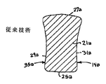
ある従来のポイント14aでは、ビット21aは、後面27aよりも幅が広い前面25aをもつ台形の横断面形状を有する。しかしながら、ビット21aは、掘削輪郭の面の軽減を提供しない。図3Aに見られるように、図2Aの(すなわち線3A−Aで沿った)掘削輪郭35aは、後面27aの方に互いに近寄る側壁29a、31aを有しない(図2A及び図3A)。むしろ、掘削輪郭35aの側壁29a、31aは、その側壁が後面の方へ伸びるにつれてだんだん大きくなるスロープで外側へ拡張する。この側壁29a、31aの外側への広がりは、カッターヘッドの大きな抵抗を生じる。掘削輪郭に対するポイント14の面の軽減の効果的な使用は、横断形状に表す側壁を単に使用することよりも抵抗の減少が良い。
At one conventional point 14a, the
ある他の実施例では、ビット21は、線6−6(図2及び図6)に沿った取り付け部分23の部分が地面中を駆動された区域まで磨耗した。取り付け部分23は、抵抗を減少するための面の軽減を提供しても、すなわち、掘削輪郭45でさえも、側壁29、31は、後面の方に互いに近寄る。掘削輪郭45の面の軽減の存在は、少ない抵抗を負い、従って、地面中を駆動させる小さな動力が必要とする。次に、減少した抵抗は、カッターヘッドが、取り付け部分が地面を貫通する点までポイントが磨耗された状態で作動し続けることを可能とする。従来のポイント14aでは、取り付け部分23aは、後面27aの方に互いに近寄る側面29a、31aをもつ台形の横断面形状を有していない。さらに、図6Aに見られるように、取り付け部分23aの前端部40aを取り囲む線6a−6aで切った掘削輪郭45aの前面25aから外方へ広がる(発散する)。掘削輪郭の面の軽減の欠如は、本発明のポイント14と比較すると、特に地面を駆動されるときにポイント14aに大きな抵抗を負わせる。この状態でポイント14aによって生じる大きな抵抗で、多くのオペレーターは、たとえビット21aが完全にぼろぼろでなくても、取り付け部分23aが地面を駆動し始めると、ポイントを取り替えるであろう。本発明では、ポイント14は、ビット21がさらにぼろぼろになるまでベース12にとどまることができる。
In certain other embodiments, the
好適な構成では、側壁29、31の先細りは、ポイント14の前端部37から後端部4
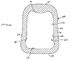
7まで続く。図7に見られるように、側壁29、31は、取り付け部分23の後部でさえも後面27の方に互いに近寄る。さらに、面の軽減は、線8−8(図2及び図8)で沿った掘削輪郭55でさえも提供され、すなわち、この後方の掘削輪郭55でさえも側壁29、31は、後面27の方に互いに近寄る。
In a preferred configuration, the taper of the
Continue to 7. As can be seen in FIG. 7, the
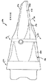
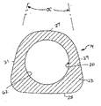
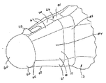
上述のように、ビット21の面の軽減を有するポイント14及び取り付け端部23の使用は、実質的にあらゆるノーズ及びソケット形状に使用されることができる。それにもかかわらず、ある好適な構成では、ノーズ18の前端部58は、凸面でかつ二つの垂直軸線を中心にして湾曲した、前方に向いた支持面60を含む(図1、図9、図11−14)。同様に、ソケット20の前端部62は、支持面60と接面する相補的に凹面で湾曲した支持面64で形成される(図1、図7、図9及び図11)。図示の構成では、前支持面60、64は、それぞれ、球面部分と合致し、例えば参照により完全に本明細書に組み込まれた米国特許第6729052号に開示されたような非軸線荷重の適用で構成要素のひずみを小さくする。
As mentioned above, the use of
好ましくは、前端部58、62は、それぞれ、ポイント14とベース12との間のガタガタするのを減少するための概ね半球形であり、全方向からの荷重をより効果的に耐える。ソケット20の前支持面64は、(すなわち、結合しないであるいは底を打たないで)さまざまなベースへのポイント14の取り付けを確実に適応させるためにその端部及び中心が半球よりもわずかに幅が広い方が望ましいが、それは、共通の荷重叉は伴う磨耗を受けてベース12の半球形状の球面に関する確実な半球形ソケットとして作用する。従来の歯10a(図2A)では、歯が地面に押し付けられるときにポイント14aは、ノーズ上であちこちに移動する。ソケット及びノーズの前端部は、平らな支持面及び鋭いコーナーで角張っている。使用中、ノーズの前端部に抗してその前端部の周りをガタガタ動くと共に、ソケット20aの後部がノーズの後端部に抗してその後端部の周りをガタガタ動くように、ポイント14aはノーズ上であちこちに移動する。この移動及びガタガタの動きは、ポイント及びノーズを磨耗させる。本発明では、概ね半球形状の前支持面60、64の使用は、ソケット20及びノーズ18の前端部でのガタガタな動きを減少する(図1及び図9)。むしろ、滑らかな連続した前支持面の使用は、ポイントがノーズを中心にして回転するのを許容し、磨耗を減少する。縦軸線28に実質的に平行な小さな帯部65は、磨耗しても所望の支持をまだ維持するノーズの付加的な能力を提供するために、概ね半球形状の支持面の後方に直線的に伸びるのが好ましい。用語“実質的に平行な”は、平行な面及び製造叉は他の目的のために(例えば、約1度乃至7度の)小さな角度で軸線28から後方に軸方向に外方へ広がる面を含むことを意味する。小さな帯部65は、軸線28に対してわずか5度で軸方向に傾斜されるのが好ましく、約2、3度で軸方向に傾斜されるのがさらに好ましい。
Preferably, the front ends 58, 62 are each generally hemispherical to reduce rattling between the
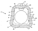
ノーズ18は、前端部58の後方に本体66を含む(図11乃至図14)。本体66は、上面68、下面69及び側面70、71によって画定される。好適な構成では、掘削の厳しさに耐えるより強度なノーズを提供するためにノーズ18が前端部58から外方に広がるように、本体の面68−71は、後方に発散する。それにもかかわらず、上面68及び下面69だけが互いから発散することができると共に、側面70、71が互いに対して実質的に平行に軸方向に伸びることができる。ソケット20は、本体66を受け入れるために前端部62の後方に主要部分76を有する。主要部分76は、本体の面68−71に適合する上壁78、下壁79及び側壁80、81を含む。好適な実施例では、本体66及び主要部分76は、それぞれ、台形状の横断面形状を有する。ノーズ18及びソケット20の長さに沿った、優れた台形形状の使用は、軸線28を中心とした磨耗部材14の回転に抵抗するために離間された隆起部として作用する四つの隅部67、77を提供する。
The
また、好適実施例では、本体の面68−71及びソケット78−81の少なくとも一つ
の面(好ましくはそれらの全ての面)は、相互に湾曲した形状を有し(図7、11及び13)、すなわち、本体の面68−71は、本体66の4つの面の各々に谷間84を画定するためにそれらの幅全体に実質的にわたってくぼんで曲がっているのが好ましい。同様に、ソケットの壁78−81は、谷間84に受け入れられる突出部86を画定するためにそれらの幅全体に実質的にわたって凸状に曲がっているのが好ましい。それらの幅全体に実質的にわたるノーズの面68−71及びソケットの壁78−81の好適な曲がりは、隅部67、77を強調し、動作中にベース12を中心としたポイント14の回転に対して増大した抵抗を提供する。また、谷間84及び突出部86は、ベース上のポイントの回転的なガタガタな動きを減少する。曲がった面68−71及び壁78−81が好ましいが、例えば参照により本明細書に組み込まれた米国特許出願第11/706582号に開示されたような他の谷間及び突出部の形状が使用されることができる。また、他の回転に抵抗する構成が使用されることができる。
Also, in a preferred embodiment, at least one surface of the body surface 68-71 and the socket 78-81 (preferably all of those surfaces) have a mutually curved shape (FIGS. 7, 11 and 13). That is, the body faces 68-71 are preferably substantially concavely bent over their entire width to define a
谷間84及び突出部86の使用、及び、特に面68−71及び壁78−81の幅全体に実質的にわたって漸進的に曲がって伸びるものの使用は、ノーズ18へのポイント14の組み入れを容易にし、すなわち、組み入れ中に、谷間84及び突出部86は、ノーズ18の適切な組み入れ位置にポイント14を協働的に導く。例えば、ポイント14が、ノーズに嵌合する際にノーズに対して適切な整合から外れてノーズ18に初期に入れられた場合、ポイントがノーズ18の奥の方に入れられるに従って、谷間84に収容される突出部86の係合が適当な整合にポイントを回転させる。この谷間84及び突出部86の協働的作用は、隅部77への隅部67の取り付け及び設置を非常に容易にすると共に大きく促進する。また、いくつかの変形は、ソケットがノーズの形状と優越して適合する限り、ソケット及びノーズの形状間で使用されることができる。
The use of
谷間84を有するノーズの面68−71は、好ましくは各々が軸方向に傾斜し、ノーズ18の後方の安定化面85に届くまでノーズ18に強度を提供するために後方に伸びるように外方に広がる。同様に、突出部86を有するソケットの壁78−81もまた面68−71に合致するように各々が広がる。また、ソケットの壁78−81は、安定化面95を画定し、安定化面85に接面する。後方の安定化面85、95は、縦軸線28に対して実質的に平行である。好適実施例では、各安定化面85、95は、軸線28に対して約7度の角度で後方に軸方向に拡散する(広がる)。また、後方安定化面85、95は、軸方向でない荷重により耐えるために、ノーズ18及びソケット20を包囲する(あるいは少なくとも実質的に包囲する)のが好ましい。様々なソケット面とノーズとの間の接触は、掘削動作中おそらく生じるであろうが、対応する前支持面60、64と後方安定化面85、95との間の接触は、歯にかかった荷重に対する重要な抵抗を提供し、それによって、所望の安定(性)を提供する。安定化面85、95は短い軸方向の伸長部で形成されるのが好ましいが、これらは長くもできるし、異なる構成にもすることができる。また、ある環境では、例えば、少ない仕事量の稼動では、安定化面85、95なしで利益が達成されることができる。
Nose surfaces 68-71 having
前支持面60、64及び後方安定化面85、95は、ノーズに対してポイントを安定にすることを提供すると共に、構成要素のひずみを小さくすることを提供する。一般に、ノーズ18及びソケット20の前端部58、62の半球形の支持面60、64は、それらの力がかかる方向に関係なく荷重に直接対抗して軸方向及び軸方向でない後方への力に安定して抵抗することができる。この曲がった連続した前支持面の使用は、ノーズに対するポイントのガタガタの動きを低減し、隅部が存在するときに別に存在する圧力の集中を減少する。後方の安定化面85、95は、ポイントの後方でのガタガタな動きを減少すると共に、参照により本明細書に組み込まれた米国特許第5709043号に開示されたようなポイントの後方部分に安定した抵抗を提供することによって、前支持面60、64を相互補完する。ノーズ18の全周囲についてあるいは少なくとも実質的に全周囲について伸び
る安定化面85、95に関し(図7、9、11−14)、それらは、あらゆる方向にかかる軸方向に導かれていない荷重を抵抗することができる。
The front support surfaces 60, 64 and the back stabilization surfaces 85, 95 provide for stabilizing the point against the nose and provide for reduced component distortion. In general, the hemispherical support surfaces 60, 64 of the
ソケット20の主要部分76は、適合的な形状のノーズ18を受け入れるために概ね台形形状の横断面形状を有する(図7及び図11)。ソケット20の概ね台形形状の横断面形状は、ポイント14の外面97の概ね台形形状の横断面形状を全体的にならう。このソケット20及び外面97の協働的形状は、ポイント14内に受け入れられることができるノーズ18のサイズを最小にし、鋳造プロセスでのポイント14の製造を容易にし、重量比率に対する強度を高める。
The
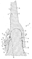
いろいろな種類の様々なロックが磨耗部材14をベース12に着脱可能に固定するのに使用されることができる。それにもかかわらず、好適実施例では、ロック16は、他の場所にも形成されることができるが好ましくは後壁27に形成された磨耗部材14の開口101の中に収容される(図1、9、15−20)。好ましくは、開口101は、軸方向に伸長した形状を有すると共に前壁103、後壁105及び側壁107、109を含む。リム111はロックの保護及び付加的な強度のために開口101の周囲に建てられている。また、リム111は、後壁105に沿って拡張されており、外面97のさらに外側に伸び、ロック16を通過するための穴113を画定する。その穴は、ロック16の位置を安定にし、オペレーターによってロックに容易にアクセスするのを許容する。
Various types of various locks can be used to removably secure the
ノーズ18は、ノーズ18の上側68から外側に突出してロック16と係合するストップ115を含む。ストップ115は、好ましくは、ロック16の前端部123が受け入れられると共に使用中に保持される凹上に曲がった凹部121を有する後面119を有するが、他の構成がロックと協働するのに使用されることができる。好適な構成では、開口101は、十分に長く、後壁27は十分に傾斜して磨耗部材14がノーズ18に組み入れられたときにストップ115に対してクリアランスを提供する。それにもかかわらず、ストップ115の通路に対して必要であれば、クリアランスのレリーフ叉は他の形状がソケット20に提供されることができる。さらに、ストップ115の突出は、ロック16の一部分を受け入れるためにくぼみ118の提供によって制限されるのが好ましい。
The
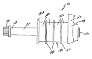
ロック16は、概ね軸方向に配向された線状ロックであり、磨耗部材14をベース12に固定し、磨耗部材14のノーズ18への嵌合を締結する。概ね軸方向に配向された線状ロックは、磨耗部材14のノーズ18への嵌合を締結するロックの機能を増大し、すなわち、取り込みの大きな長さを提供する。好適な実施例では、ロック16は、前端部123とヘッド134を有する後端部とを有する螺子付きシャフト130と、シャフト130に螺合されたナット136と、スプリング138とを含む(図1、9、15−20)。スプリング138は、好ましくはワッシャーの形態であるスペーサ142によって分離された、発泡体、ゴムあるいは他の弾性材料で構成された一連のエラストマーディスク140で形成されるのが好ましい。複数のディスク140は、十分な力、弾性、取り込みを提供するのに使用される。ワッシャーは、エラストマーディスクが一連の個々のスプリング部材として作用するようにエラストマーディスクを分離する。ワッシャー142は、プラスチックで構成されるのが好ましいが、他の材料で作られることができる。さらに、好適な構成のスプリングは、シャフト130に作り組み入れるのに経済的である。それにもかかわらず、他の種類のスプリングが使用されることができる。スラストワッシャー142a叉は他の手段が十分な支持を提供するためにスプリングの端部に提供されるのが好ましい。
The
シャフト130は、スプリング138を中心的に貫通してナット136と係合する。シャフト130の前端部123は、凹部121の中に嵌り、シャフト130が支持のためのストップ115に設置される。ロック16の後端部134は、磨耗部材14の穴113を貫通し、使用者は、開口101の外部でロックを利用することができる。ヘッド134が
より容易に利用されるようにシャフトは軸線28に対して角度をなして設置されるのが好ましい。スプリング138は、ロックが締結されるときに磨耗部材に付勢力をかけることができるように後壁105とナット136との間に設定される。穴113はヘッド134がロック16のアッセンブリ10への取り付け中通過することができるためにヘッドよりも大きい方が好ましい。また、シャフト130を単に上方から挿入することに対応するために穴113は、オープンスロットとして形成されることができる。構造と係合する他の手段が図示のヘッド134の代わりに使用されることができる。
The
使用では、磨耗部材14は、ノーズ18上を摺動し、ノーズ18がソケット20の中に嵌合する(図1及び図9)。ロックは、開口101の外側にあるシャフト130に取り付けられる着脱可能なリテイナー(例えば単なるワイヤリボン)によって、出荷、保管及び/叉は設置のために穴113に暫定的に保持されることができ、あるいは、ロックは磨耗部材がノーズに嵌合された後に取り付けられることができる。とにかく、シャフト130は、穴113に挿入され、その先端はストップ115の凹部121に設置される。ロック16は、ノーズ18の外面に沿って横たわるように配置されるため、荷重に抵抗するためのロックを収容するために穴、スロットあるいは同様なものはノーズに形成される必要がない。ヘッド134は、ツールに係合されツールによって回転されて、磨耗部材を保持するために圧縮状態にロックを締結する。すなわち、シャフト130は、ナット136に対して回転させられ、前端部123がストップ115を押圧する。次に、この動きは、ナット136をスプリング138の後方に引き、スプリングはナット136と後壁105との間で圧縮される。このロックの締結は、使用中のきちんとした嵌合のため及び磨耗しないために、磨耗部材14をノーズ18上できつく(すなわち、前支持面60、64が係合された状態で)引っ張る。続けられたシャフト130の回転はさらにスプリング138を圧縮する。そして、圧縮されたスプリング138は、ノーズ及びソケットが磨耗し始めるにつれて磨耗部材14を後方に付勢する。好適なノーズ18及びポイント14の安定(性)は、軸方向のロックの使用を許容する。すなわち、実質的に曲げ(応)力がロックにかからず、ボルトの軸方向の高い圧縮力を磨耗部材をベースに保持するのに使用することができる。ロック16は、軽量で、打ち子がなく(ハンマーレス)、製造が容易であり、大きなスペースを使用とせず、そして、ノーズにあらゆる開口を必要としない。
In use, the
好適な構成では、ロック16は、また、ナット136に関連してシャフト130に嵌合するインジケーター146を含む(図15−20)。インジケーター146は、鋼鉄あるいは他の強固な材料で形成されたプレートであるのが好ましく、側縁部148、149は、開口101の側壁107、109に接近して適合された側縁部148、149を有するが、開口101の中にぴったりと嵌合していない。インジケーター146は、シャフト130が回転されたときにナットの回転を防止するためにナット136を完全に叉は部分的に収容する開口を含む。側壁107、109に対する側縁部148、149の接近した受容は、インジケーター146が回転するのを防止する。代替的に、インジケーターは、ナットとして機能する螺子付ボアを有することができ、インジケーターが省略された場合には他の手段がナット136を回転しないように保持することが必要とされる。また、インジケーター146は、ナット136から分離することができる。
In a preferred configuration, lock 16 also includes an
インジケーター146は、シャフト130及び/叉はスプリング138に過度の力をかけないで磨耗部材に所望の圧力をかけるためにシャフト130が適当に締結されたときの視覚的表示を提供する。好適な構成では、インジケーター146は、開口101に沿って、例えばリム111及び/叉は側壁107、109に沿って形成されたマーカー152と協働する。マーカー152は、側壁107、109の一方叉は双方に沿ってリム111にあるのが好ましいが他の構成を有することができる。マーカー146は、縁部あるいは単なる表示よりもすぐれた構造であるのが好ましく、初期の締結時と同様に、磨耗が発生し始めるときにロック16を再度締結するのに使用されることができる。
シャフト130が回転されてナット136が後方に引っ張られると、インジケーター146は、開口101内でナット136と共に(図16の位置から)後方に動く。インジケーター146がマーカー152と整合すると(図15)、オペレーターは締結を止めることがわかる。この位置で、ノーズ及び/叉はソケットの磨耗に関係なく、磨耗部材14に予め決められた力をかける。従って、ロックの締結不足及び過締結を容易に避けることができる。代替として、インジケーター146を省略することができ、シャフト130は、予め決められたトルク量まで締結されることができる。
As the
本発明のさまざまな特徴が最適な実施及び利点に対して互いに使用されるのが好ましい。それにもかかわらず、さまざまな特徴が個々に使用されることができ、それらが各々提供する有益を提供する。 It is preferred that the various features of the present invention be used together for optimal implementation and advantages. Nevertheless, various features can be used individually, providing the benefits each provides.
本発明のさまざまな特徴が最適な実施及び利点に対して互いに使用されるのが好ましい。それにもかかわらず、さまざまな特徴が個々に使用されることができ、それらが各々提供する有益を提供する。
以上説明したように、本発明は以下の形態を有する。
[形態1]
掘削装置のための磨耗部材であって、
縦軸線に沿って概ね整合された作用部分及び取り付け部分であって、取り付け部分は掘削装置に固定されたベースを受け入れるためのソケットを含む、作用部分及び取り付け部分と、
掘削作業中に地面中を磨耗部材が推進する間、前方面になるように適合された前面と、
地面中を磨耗部材が推進する間、後方面になるように適合された後面とを備え、
前面及び後面は、作用部分及び取り付け部分にわたって軸方向に伸び、取り付け部分の少なくとも一部に沿った縦軸線に垂直な横断面に関して前面は後面よりも大きな幅を有する磨耗部材。
[形態2]
形態1記載の磨耗部材において、
磨耗部材をベースに固定するためのロックを受け入れる開口を含む磨耗部材。
[形態3]
形態1記載の磨耗部材において、
作用部分は、細長いビットである磨耗部材。
[形態4]
形態1記載の磨耗部材において、
取り付け部分は、縦軸線に垂直な概ね台形の横断面形状を有する磨耗部材。
[形態5]
形態4記載の磨耗部材において、
作用部分は、縦軸線に垂直な概ね台形の横断面形状を有する磨耗部材。
[形態6]
形態4記載の磨耗部材において、
取り付け部分の実質的に全長さは、縦軸線に垂直な概ね台形の横断面形状を有する磨耗部材。
[形態7]
形態1記載の磨耗部材において、
ベースに形成された谷間に勘合する突出部を画定するために、ソケットの少なくとも一つの壁は内方に曲がっている磨耗部材。
[形態8]
形態1記載の磨耗部材において、
ソケットは、概ね台形の横断面形状を有する磨耗部材。
[形態9]
形態8記載の磨耗部材において、
台形形状を画定するソケットの各壁は、壁の幅全体に実質的にわたって概ね凸状に曲がった形状を有する磨耗部材。
[形態10]
形態1記載の磨耗部材において、
作用部分の少なくとも一部に沿った縦軸線に垂直な横断面に関して前面は後面よりも大きな幅を有する磨耗部材。
[形態11]
掘削装置のための磨耗部材であって、
縦軸線に沿って概ね整合された作用部分及び取り付け部分であって、取り付け部分は掘削装置に固定されたベースを受け入れるためのソケットを含む、作用部分及び取り付け部分と、
掘削作業中に地面中を磨耗部材が推進する間、前方面になるように適合された前面と、
地面中を磨耗部材が推進する間、後方面になるように適合された後面とを備え、
前面及び後面は、作用部分及び取り付け部分にわたって軸方向に伸び、前面と後面との間に伸びる側壁が、取り付け部分の少なくとも前部分の掘削輪郭の後面の方へ概ね互いに近寄り、掘削輪郭は、掘削路の中心ポイントで地面中の移動方向に平らに伸びると共に、少なくとも一つの掘削角度に対して縦軸線に対して横方向に垂直に伸びる横断面である磨耗部材。
[形態12]
形態11記載の磨耗部材において、
磨耗部材をベースに固定するためのロックを受け入れる開口を含む磨耗部材。
[形態13]
形態11記載の磨耗部材において、
側壁は、取り付け部分の長さ全体に実質的にわたる掘削輪郭の後面の方へ概ね互いに近寄る磨耗部材。
[形態14]
形態11記載の磨耗部材において、
作用部分は、細長いビットである磨耗部材。
[形態15]
掘削装置のための磨耗部材であって、
縦軸線に沿って概ね整合された作用部分及び取り付け部分を備え、
取り付け部分は掘削装置に固定されたベースを受け入れるためのソケットを含み、
ソケットは、縦軸線に対して概ね台形形状の横断面を有し、各々が内方に湾曲に曲がった面によって画定される磨耗部材。
[形態16]
形態15記載の磨耗部材において、
ソケットの面は、面の幅全体に実質的にわたって内方に曲がっている磨耗部材。
[形態17]
形態15記載の磨耗部材において、
ソケットの前端部は、概ね半球形の前支持面を含む磨耗部材。
[形態18]
形態15記載の磨耗部材において、
磨耗部材をベースに固定するためのロックを受け入れる開口を含む磨耗部材。
[形態19]
掘削装置のための磨耗部材であって、
縦軸線に沿って概ね整合された作用部分及び取り付け部分を備え、
取り付け部分は掘削装置に固定されたベースを受け入れるためのソケットを含み、
ソケットは、概ね半球形の前支持面を画定する前端部と、前端部の後方に主要部分とを含む磨耗部材。
[形態20]
形態19記載の磨耗部材において、
主要部分は、縦軸線に対して概ね台形形状の横断面を有する磨耗部材。
[形態21]
形態19記載の磨耗部材において、
主要部分は、縦軸線に対して実質的に平行に軸方向に伸びる少なくとも一つの安定化面を含む磨耗部材。
[形態22]
形態19記載の磨耗部材において、
磨耗部材をベースに固定するためのロックを受け入れる開口を含む磨耗部材。
[形態23]
掘削装置のための磨耗部材であって、
縦軸線に沿って概ね整合された作用部分及び取り付け部分を備え、
取り付け部分は掘削装置に固定されたベースを受け入れるためのソケットを含み、
ソケットは、縦軸線に対して垂直である二つの軸線を中心にして凹状に曲がった前支持面を画定する前端部と、縦軸線に対して概ね台形形状の横断面を有する前端部の後方に主要部分とを含む磨耗部材。
[形態24]
形態23記載の磨耗部材において、
磨耗部材をベースに固定するためのロックを受け入れる開口を含む磨耗部材。
[形態25]
掘削装置のための磨耗部材であって、
縦軸線に沿って概ね整合された作用部分及び取り付け部分を備え、
取り付け部分は掘削装置に固定されたベースを受け入れるためのソケットを含み、
ソケットは、概ね半球形の前支持面を画定する前端部と、前端部の後方に主要部分とを含み、
主要部分は、縦軸線に対して実質的に平行に軸方向に伸びると共にソケットの外周を実質的に横切って伸びる安定化面を含む磨耗部材。
[形態26]
形態25記載の磨耗部材において、
主要部分は、縦軸線に対して横切る概ね台形形状の横断面を有する磨耗部材。
[形態27]
形態25記載の磨耗部材において、
磨耗部材をベースに固定するためのロックを受け入れる開口を含む磨耗部材。
[形態28]
掘削装置のための磨耗部材であって、縦軸線に沿って概ね整合された作用部分及び取り付け部分を備え、
取り付け部分は、掘削装置に固定されたベースを受け入れるためのソケットと、磨耗部材を掘削装置に着脱可能に保持するロックを受け入れるためにソケットと連通した開口とを含み、
開口は、前壁及び後壁を有し、後壁は、ロックの締結のためにオペレーターが容易に利用するためにロックが縦軸線に対して傾斜した角度で開口から貫通する穴を含む磨耗部材。
[形態29]
形態28記載の磨耗部材において、
ロックが十分に締結されたときにオペレーターに視覚的表示を提供するためにマーカーが開口に隣接して提供される磨耗部材。
[形態30]
形態28記載の磨耗部材において、
ソケットは、穴の後方に配置された、縦軸線に対して実質的に平行に軸方向に伸びる後安定化面を含む磨耗部材。
[形態31]
掘削装置のための磨耗アッセンブリであって、
掘削装置に固定されたベースと、
縦軸線に沿って概ね整合された作用部分及び取り付け部分を有する磨耗部材とを備え、
取り付け部分は、掘削装置に固定されたベースを受け入れるためのソケットと、掘削作業中に地面中を磨耗部材が推進する間、前方面になるように適合された前面と、地面中を磨耗部材が推進する間、後方面になるように適合された後面とを含み、前面及び後面は、作用部分及び取り付け部分にわたって軸方向に伸び、取り付け部分の少なくとも一部に沿った縦軸線に垂直な横断面に関して前面は後面よりも大きな幅を有し、磨耗アッセンブリは、更に、磨耗部材をベースに着脱可能に固定するためのロックを備える磨耗アッセンブリ。
[形態32]
形態31記載の磨耗アッセンブリにおいて、
ベースは、ソケットの中に受け入れられたノーズを含み、ノーズ及びソケットは、各々、縦軸線に垂直な概ね台形の横断面形状を有する磨耗アッセンブリ。
[形態33]
形態31記載の磨耗アッセンブリにおいて、
ベースは、ソケットの中に受け入れられたノーズを含み、ノーズは複数の谷間を含み、ソケットは、谷間に受け入れられる複数の突出部を含む磨耗アッセンブリ。
[形態34]
掘削装置のための磨耗アッセンブリであって、
掘削装置に固定されたベースと、
縦軸線に沿って概ね整合された作用部分及び取り付け部分を有する磨耗部材とを備え、
取り付け部分は、掘削装置に固定されたベースを受け入れるためのソケットと、掘削作業中に地面中を磨耗部材が推進する間、前方面になるように適合された前面と、地面中を磨耗部材が推進する間、後方面になるように適合された後面とを含み、
前面と後面との間に伸びる側壁が、取り付け部分の少なくとも前部分の掘削輪郭の後面の方へ概ね互いに近寄り、掘削輪郭は、掘削路の中心ポイントで地面中の移動方向に平らに伸びると共に、少なくとも一つの掘削角度に対して縦軸線に対して横方向に垂直に伸びる横断面であり、磨耗アッセンブリは、更に、磨耗部材をベースに着脱可能に固定するためのロックを備える磨耗アッセンブリ。
[形態35]
掘削装置のための磨耗アッセンブリであって、
掘削装置に固定されたベースと、
縦軸線に沿って概ね整合された作用部分及び取り付け部分を有する磨耗部材とを備え、
取り付け部分は、縦軸線に対して概ね台形形状の横断面を有すると共に各々が内方に湾曲に曲がった面によって画定されるソケットを有し、磨耗アッセンブリは、更に、磨耗部材をベースに着脱可能に固定するためのロックを備える磨耗アッセンブリ。
[形態36]
形態31記載の磨耗アッセンブリにおいて、
ベースは、ソケットの形状に実質的に合致するために、縦軸線に対して概ね台形形状の横断面を有するノーズを含む磨耗アッセンブリ。
[形態37]
掘削装置のための磨耗アッセンブリであって、
掘削装置に固定されると共に、第1面を含むベースと、
縦軸線に沿って概ね整合された作用部分及び取り付け部分を有する磨耗部材とを備え、
取り付け部分は、ベースを受け入れるソケットと、第2面を有する開口とを有し、
磨耗アッセンブリは、更に、
縦軸線と概ね同じ方向に配向され、磨耗部材をベースに着脱可能に保持するために圧縮状態に第1面と第2面との間に嵌合する細長いロックを備える磨耗アッセンブリ。
[形態38]
形態37記載の磨耗アッセンブリにおいて、
ロックは、第1面に抗する螺子付シャフトと、螺子付シャフトに螺合されるナットと、第2面とナットの間で圧縮される、シャフトを中心としたスプリングとを含む磨耗アッセンブリ。
[形態39]
磨耗部材を掘削装置に取り付けるための方法であって、
ノーズがソケットの中に受け入れられるように掘削装置に固定されたノーズに、ソケットを有する磨耗部材を嵌合することと、
磨耗部材の開口に細長いロックを配置し、ロックの第1の支持面がノーズの支持面に合致し、ロックの第2の支持面が磨耗部材の支持面に合致し、ロックの縦軸線が、磨耗部材がノーズに嵌合する方向に概ね配向されることと、
ノーズへの磨耗部材の嵌合を締結するためにロックを調整し、磨耗部材をベースに保持するために圧縮状態にロックをすることとを備える方法。
[形態40]
形態39記載の方法において、
ロックは、第1面に抗する螺子付シャフトと、螺子付シャフトに螺合されるナットと、第2面とナットの間で圧縮される、シャフトを中心としたスプリングとを含む方法。
[形態41]
磨耗部材を掘削装置に取り付けるための方法であって、
ノーズの一方側から外方に突出するストップを有する、掘削装置に固定されたノーズを提供することと、
ノーズにソケットを有する磨耗部材を嵌合し、磨耗部材を貫通する開口がストップの後方にストップと概ね軸方向に整合して配置されることと、
ロックをストップと開口の壁に接するようにノーズの外面に沿って配置し、磨耗部材をノーズに着脱可能に保持することとを備える方法。
[形態42]
形態41記載の方法において、
ストップと開口の壁との間で圧縮状態にされるようにロックが締結される方法。
[形態43]
磨耗部材を掘削装置に取り付けるための方法であって、
ノーズがソケットの中に受け入れられるように掘削装置に固定されたノーズに、ソケットを有する磨耗部材を嵌合することと、
ロックの第1の支持面がノーズの支持面に合致し、ロックの第2の支持面が磨耗部材の支持面に合致するようにロックを配置することと、
ロックの視覚的インジケーターが磨耗部材のマーカーと概ね整合するまで、ノーズへの磨耗部材の嵌合を締結するためにロックを調整することとを備える方法。
[形態44]
磨耗部材を掘削装置に固定されたベースに着脱可能に固定するためのロックであって、
ロックは、支持端部及びツールと係合する端部とを有する直線状の螺子付シャフトと、螺子付シャフトに螺合されるナットと、交互に配置されると共に、支持端部とナットの間でシャフトを中心にして嵌合した、複数の環状のエラストマーディスク及び環状のスペーサを含むスプリングとを備えるロック。
It is preferred that the various features of the present invention be used together for optimal implementation and advantages. Nevertheless, various features can be used individually, providing the benefits each provides.
As described above, the present invention has the following modes.
[Form 1]
A wear member for a drilling rig,
An action portion and an attachment portion generally aligned along the longitudinal axis, the attachment portion including a socket for receiving a base secured to the drilling rig;
A front face adapted to be the front face while the wear member propels through the ground during excavation operations;
A rear surface adapted to be a rear surface while the wear member is propelled in the ground,
A wear member having a front surface and a rear surface extending axially over the working portion and the mounting portion, the front surface having a width greater than the rear surface with respect to a cross section perpendicular to the longitudinal axis along at least a portion of the mounting portion.
[Form 2]
In the wear member according to aspect 1,
A wear member including an opening for receiving a lock for securing the wear member to the base.
[Form 3]
In the wear member according to aspect 1,
The working part is a wear member which is an elongated bit.
[Form 4]
In the wear member according to aspect 1,
The mounting portion is a wear member having a generally trapezoidal cross-sectional shape perpendicular to the longitudinal axis.
[Form 5]
In the wear member according to mode 4,
The working portion is a wear member having a generally trapezoidal cross-sectional shape perpendicular to the longitudinal axis.
[Form 6]
In the wear member according to mode 4,
A wear member having a substantially trapezoidal cross-sectional shape with a substantially full length of the attachment portion perpendicular to the longitudinal axis.
[Form 7]
In the wear member according to aspect 1,
A wear member in which at least one wall of the socket is bent inward to define a protrusion that fits into a valley formed in the base.
[Form 8]
In the wear member according to aspect 1,
The socket is a wear member having a generally trapezoidal cross-sectional shape.
[Form 9]
In the wear member according to aspect 8,
Each wall of the socket defining a trapezoidal shape is a wear member having a generally convex bent shape substantially over the entire width of the wall.
[Mode 10]
In the wear member according to aspect 1,
A wear member having a front surface with a greater width than a rear surface with respect to a cross section perpendicular to the longitudinal axis along at least a portion of the working portion.
[Form 11]
A wear member for a drilling rig,
An action portion and an attachment portion generally aligned along the longitudinal axis, the attachment portion including a socket for receiving a base secured to the drilling rig;
A front face adapted to be the front face while the wear member propels through the ground during excavation operations;
A rear surface adapted to be a rear surface while the wear member is propelled in the ground,
The front and rear surfaces extend axially across the working and mounting portions, with the sidewalls extending between the front and rear surfaces being generally closer to each other towards the rear surface of the drilling contour at least at the front portion of the mounting portion, A wear member that is a transverse section that extends flat in the direction of travel in the ground at the center point of the road and that extends perpendicular to the longitudinal axis with respect to at least one excavation angle.
[Form 12]
In the wear member according to form 11,
A wear member including an opening for receiving a lock for securing the wear member to the base.
[Form 13]
In the wear member according to form 11,
Wear members whose sidewalls generally approach each other toward the back of the digging profile substantially throughout the length of the mounting portion.
[Form 14]
In the wear member according to form 11,
The working part is a wear member which is an elongated bit.
[Form 15]
A wear member for a drilling rig,
A working portion and a mounting portion generally aligned along the longitudinal axis;
The mounting part includes a socket for receiving a base fixed to the drilling rig;
The socket is a wear member having a generally trapezoidal cross section with respect to the longitudinal axis, each defined by an inwardly curved surface.
[Form 16]
In the wear member according to form 15,
A wear member in which the face of the socket is bent inward substantially over the entire width of the face.
[Form 17]
In the wear member according to form 15,
A wear member wherein the front end of the socket includes a generally hemispherical front support surface.
[Form 18]
In the wear member according to form 15,
A wear member including an opening for receiving a lock for securing the wear member to the base.
[Form 19]
A wear member for a drilling rig,
A working portion and a mounting portion generally aligned along the longitudinal axis;
The mounting part includes a socket for receiving a base fixed to the drilling rig;
The socket is a wear member that includes a front end defining a generally hemispherical front support surface and a main portion behind the front end.
[Form 20]
In the wear member according to
The main part is a wear member having a generally trapezoidal cross section with respect to the longitudinal axis.
[Form 21]
In the wear member according to
The wear member includes a main portion including at least one stabilizing surface extending axially substantially parallel to the longitudinal axis.
[Form 22]
In the wear member according to
A wear member including an opening for receiving a lock for securing the wear member to the base.
[Form 23]
A wear member for a drilling rig,
A working portion and a mounting portion generally aligned along the longitudinal axis;
The mounting part includes a socket for receiving a base fixed to the drilling rig;
The socket has a front end that defines a front support surface that is bent concavely about two axes that are perpendicular to the longitudinal axis, and a rear end that has a generally trapezoidal cross section with respect to the longitudinal axis. A wear member including a main portion.
[Form 24]
In the wear member according to
A wear member including an opening for receiving a lock for securing the wear member to the base.
[Form 25]
A wear member for a drilling rig,
A working portion and a mounting portion generally aligned along the longitudinal axis;
The mounting part includes a socket for receiving a base fixed to the drilling rig;
The socket includes a front end defining a generally hemispherical front support surface and a main portion behind the front end;
The wear member includes a stabilizing surface that extends axially substantially parallel to the longitudinal axis and that extends substantially across the outer periphery of the socket.
[Form 26]
In the wear member according to
The main part is a wear member having a generally trapezoidal cross section transverse to the longitudinal axis.
[Form 27]
In the wear member according to
A wear member including an opening for receiving a lock for securing the wear member to the base.
[Form 28]
A wear member for a drilling rig, comprising a working portion and a mounting portion generally aligned along a longitudinal axis;
The mounting portion includes a socket for receiving a base secured to the drilling rig, and an opening in communication with the socket for receiving a lock that removably holds the wear member to the drilling rig,
The opening has a front wall and a rear wall, and the rear wall includes a wear member that includes a hole through which the lock penetrates from the opening at an angle with respect to the longitudinal axis for easy use by an operator for fastening the lock. .
[Form 29]
The wear member according to
A wear member in which a marker is provided adjacent to the opening to provide a visual indication to the operator when the lock is fully tightened.
[Form 30]
The wear member according to
The socket is a wear member that includes a post-stabilizing surface that is disposed behind the hole and extends axially substantially parallel to the longitudinal axis.
[Form 31]
A wear assembly for a drilling rig,
A base fixed to the drilling rig;
A wear member having a working portion and a mounting portion generally aligned along the longitudinal axis;
The mounting portion includes a socket for receiving a base fixed to the drilling rig, a front surface adapted to be a front surface while the wear member is propelled through the ground during excavation work, and a wear member through the ground. A rear surface adapted to be a rear surface during propulsion, the front surface and the rear surface extending axially over the working portion and the mounting portion and perpendicular to a longitudinal axis along at least a portion of the mounting portion The front surface has a width greater than the rear surface, and the wear assembly further comprises a lock for removably securing the wear member to the base.
[Form 32]
The wear assembly according to
The base includes a nose received in the socket, the nose and the socket each having a generally trapezoidal cross-sectional shape perpendicular to the longitudinal axis.
[Form 33]
The wear assembly according to
The base includes a nose received in the socket, the nose including a plurality of valleys, and the socket includes a plurality of protrusions received in the valleys.
[Form 34]
A wear assembly for a drilling rig,
A base fixed to the drilling rig;
A wear member having a working portion and a mounting portion generally aligned along the longitudinal axis;
The mounting portion includes a socket for receiving a base fixed to the drilling rig, a front surface adapted to be a front surface while the wear member is propelled through the ground during excavation work, and a wear member through the ground. A rear surface adapted to be a rear surface during propulsion,
Side walls extending between the front and rear surfaces generally approach each other towards the rear surface of the drilling contour of at least the front portion of the mounting portion, the drilling contour extends flat in the direction of movement in the ground at the center point of the drilling tract, A wear assembly, wherein the wear assembly further comprises a lock for removably securing the wear member to the base, wherein the wear assembly is a cross section extending perpendicular to the longitudinal axis for at least one excavation angle.
[Form 35]
A wear assembly for a drilling rig,
A base fixed to the drilling rig;
A wear member having a working portion and a mounting portion generally aligned along the longitudinal axis;
The mounting portion has a generally trapezoidal cross section with respect to the longitudinal axis and has sockets each defined by an inwardly curved surface, and the wear assembly is further detachable from the wear member base Wear assembly with a lock to secure to
[Form 36]
The wear assembly according to
A wear assembly, wherein the base includes a nose having a generally trapezoidal cross section with respect to the longitudinal axis to substantially match the shape of the socket.
[Form 37]
A wear assembly for a drilling rig,
A base secured to the drilling rig and including a first surface;
A wear member having a working portion and a mounting portion generally aligned along the longitudinal axis;
The mounting portion has a socket for receiving the base and an opening having a second surface;
The wear assembly
A wear assembly comprising an elongated lock that is oriented generally in the same direction as the longitudinal axis and fits between a first surface and a second surface in a compressed state to removably retain the wear member on the base.
[Form 38]
The wear assembly of
The lock includes a threaded shaft that resists a first surface, a nut that is screwed onto the threaded shaft, and a spring centered on the shaft that is compressed between the second surface and the nut.
[Form 39]
A method for attaching a wear member to a drilling rig,
Fitting a wear member having a socket to a nose secured to the drilling rig such that the nose is received in the socket;
An elongated lock is disposed in the opening of the wear member, the first support surface of the lock matches the support surface of the nose, the second support surface of the lock matches the support surface of the wear member, and the longitudinal axis of the lock is The wear member is generally oriented in a direction to fit the nose;
Adjusting the lock to fasten the fit of the wear member to the nose and locking in the compressed state to hold the wear member to the base.
[Form 40]
The method of embodiment 39,
The lock includes a threaded shaft that resists a first surface, a nut that is screwed to the threaded shaft, and a spring centered on the shaft that is compressed between the second surface and the nut.
[Form 41]
A method for attaching a wear member to a drilling rig,
Providing a nose secured to the drilling rig having a stop projecting outwardly from one side of the nose;
Fitting a wear member having a socket to the nose, and an opening penetrating the wear member disposed behind the stop in a generally axial alignment with the stop;
Placing the lock along the outer surface of the nose so as to contact the stop and the wall of the opening, and holding the wear member removably on the nose.
[Form 42]
The method of claim 41,
A method in which a lock is fastened so that it is compressed between the stop and the wall of the opening.
[Form 43]
A method for attaching a wear member to a drilling rig,
Fitting a wear member having a socket to a nose secured to the drilling rig such that the nose is received in the socket;
Positioning the lock such that the first support surface of the lock matches the support surface of the nose and the second support surface of the lock matches the support surface of the wear member;
Adjusting the lock to tighten the fit of the wear member to the nose until the visual indicator of the lock is generally aligned with the wear member marker.
[Form 44]
A lock for detachably fixing the wear member to a base fixed to the excavator,
The locks are alternately disposed with a linear threaded shaft having a support end and an end engaged with the tool, a nut threadedly engaged with the threaded shaft, and between the support end and the nut. And a spring comprising a plurality of annular elastomeric discs and an annular spacer, fitted around the shaft.
Claims (44)
縦軸線に沿って概ね整合された作用部分及び取り付け部分であって、取り付け部分は掘削装置に固定されたベースを受け入れるためのソケットを含む、作用部分及び取り付け部分と、
掘削作業中に地面中を磨耗部材が推進する間、前方面になるように適合された前面と、
地面中を磨耗部材が推進する間、後方面になるように適合された後面とを備え、
前面及び後面は、作用部分及び取り付け部分にわたって軸方向に伸び、取り付け部分の少なくとも一部に沿った縦軸線に垂直な横断面に関して前面は後面よりも大きな幅を有する磨耗部材。 A wear member for a drilling rig,
An action portion and an attachment portion generally aligned along the longitudinal axis, the attachment portion including a socket for receiving a base secured to the drilling rig;
A front face adapted to be the front face while the wear member propels through the ground during excavation operations;
A rear surface adapted to be a rear surface while the wear member is propelled in the ground,
A wear member having a front surface and a rear surface extending axially over the working portion and the mounting portion, the front surface having a width greater than the rear surface with respect to a cross section perpendicular to the longitudinal axis along at least a portion of the mounting portion.
磨耗部材をベースに固定するためのロックを受け入れる開口を含む磨耗部材。 The wear member according to claim 1,
A wear member including an opening for receiving a lock for securing the wear member to the base.
作用部分は、細長いビットである磨耗部材。 The wear member according to claim 1,
The working part is a wear member which is an elongated bit.
取り付け部分は、縦軸線に垂直な概ね台形の横断面形状を有する磨耗部材。 The wear member according to claim 1,
The mounting portion is a wear member having a generally trapezoidal cross-sectional shape perpendicular to the longitudinal axis.
作用部分は、縦軸線に垂直な概ね台形の横断面形状を有する磨耗部材。 The wear member according to claim 4,
The working portion is a wear member having a generally trapezoidal cross-sectional shape perpendicular to the longitudinal axis.
取り付け部分の実質的に全長さは、縦軸線に垂直な概ね台形の横断面形状を有する磨耗部材。 The wear member according to claim 4,
A wear member having a substantially trapezoidal cross-sectional shape with a substantially full length of the attachment portion perpendicular to the longitudinal axis.
ベースに形成された谷間に勘合する突出部を画定するために、ソケットの少なくとも一つの壁は内方に曲がっている磨耗部材。 The wear member according to claim 1,
A wear member in which at least one wall of the socket is bent inward to define a protrusion that fits into a valley formed in the base.
ソケットは、概ね台形の横断面形状を有する磨耗部材。 The wear member according to claim 1,
The socket is a wear member having a generally trapezoidal cross-sectional shape.
台形形状を画定するソケットの各壁は、壁の幅全体に実質的にわたって概ね凸状に曲がった形状を有する磨耗部材。 The wear member according to claim 8,
Each wall of the socket defining a trapezoidal shape is a wear member having a generally convex bent shape substantially over the entire width of the wall.
作用部分の少なくとも一部に沿った縦軸線に垂直な横断面に関して前面は後面よりも大きな幅を有する磨耗部材。 The wear member according to claim 1,
A wear member having a front surface with a greater width than a rear surface with respect to a cross section perpendicular to the longitudinal axis along at least a portion of the working portion.
縦軸線に沿って概ね整合された作用部分及び取り付け部分であって、取り付け部分は掘削装置に固定されたベースを受け入れるためのソケットを含む、作用部分及び取り付け部分と、
掘削作業中に地面中を磨耗部材が推進する間、前方面になるように適合された前面と、
地面中を磨耗部材が推進する間、後方面になるように適合された後面とを備え、
前面及び後面は、作用部分及び取り付け部分にわたって軸方向に伸び、
前面と後面との間に伸びる側壁が、取り付け部分の少なくとも前部分の掘削輪郭の後面の方へ概ね互いに近寄り、
掘削輪郭は、掘削路の中心ポイントで地面中の移動方向に平らに伸びると共に、少なくとも一つの掘削角度に対して縦軸線に対して横方向に垂直に伸びる横断面である磨耗部材。 A wear member for a drilling rig,
An action portion and an attachment portion generally aligned along the longitudinal axis, the attachment portion including a socket for receiving a base secured to the drilling rig;
A front face adapted to be the front face while the wear member propels through the ground during excavation operations;
A rear surface adapted to be a rear surface while the wear member is propelled in the ground,
The front and rear surfaces extend axially across the working and mounting portions,
Side walls extending between the front and rear surfaces generally approach each other toward the rear surface of the excavation profile of at least the front portion of the attachment portion;
The excavation profile is a wear member that is a cross section that extends flat in the direction of movement in the ground at the center point of the excavation path and that extends perpendicular to the longitudinal axis with respect to at least one excavation angle.
磨耗部材をベースに固定するためのロックを受け入れる開口を含む磨耗部材。 The wear member according to claim 11,
A wear member including an opening for receiving a lock for securing the wear member to the base.
側壁は、取り付け部分の長さ全体に実質的にわたる掘削輪郭の後面の方へ概ね互いに近寄る磨耗部材。 The wear member according to claim 11,
Wear members whose sidewalls generally approach each other toward the back of the digging profile substantially throughout the length of the mounting portion.
作用部分は、細長いビットである磨耗部材。 The wear member according to claim 11,
The working part is a wear member which is an elongated bit.
縦軸線に沿って概ね整合された作用部分及び取り付け部分を備え、
取り付け部分は掘削装置に固定されたベースを受け入れるためのソケットを含み、
ソケットは、縦軸線に対して概ね台形形状の横断面を有し、各々が内方に湾曲に曲がった面によって画定される磨耗部材。 A wear member for a drilling rig,
A working portion and a mounting portion generally aligned along the longitudinal axis;
The mounting part includes a socket for receiving a base fixed to the drilling rig;
The socket is a wear member having a generally trapezoidal cross section with respect to the longitudinal axis, each defined by an inwardly curved surface.
ソケットの面は、面の幅全体に実質的にわたって内方に曲がっている磨耗部材。 The wear member of claim 15,
A wear member in which the face of the socket is bent inward substantially over the entire width of the face.
ソケットの前端部は、概ね半球形の前支持面を含む磨耗部材。 The wear member of claim 15,
A wear member wherein the front end of the socket includes a generally hemispherical front support surface.
磨耗部材をベースに固定するためのロックを受け入れる開口を含む磨耗部材。 The wear member of claim 15,
A wear member including an opening for receiving a lock for securing the wear member to the base.
縦軸線に沿って概ね整合された作用部分及び取り付け部分を備え、
取り付け部分は掘削装置に固定されたベースを受け入れるためのソケットを含み、
ソケットは、概ね半球形の前支持面を画定する前端部と、前端部の後方に主要部分とを含む磨耗部材。 A wear member for a drilling rig,
A working portion and a mounting portion generally aligned along the longitudinal axis;
The mounting part includes a socket for receiving a base fixed to the drilling rig;
The socket is a wear member that includes a front end defining a generally hemispherical front support surface and a main portion behind the front end.
主要部分は、縦軸線に対して概ね台形形状の横断面を有する磨耗部材。 The wear member of claim 19,
The main part is a wear member having a generally trapezoidal cross section with respect to the longitudinal axis.
主要部分は、縦軸線に対して実質的に平行に軸方向に伸びる少なくとも一つの安定化面を含む磨耗部材。 The wear member of claim 19,
The wear member includes a main portion including at least one stabilizing surface extending axially substantially parallel to the longitudinal axis.
磨耗部材をベースに固定するためのロックを受け入れる開口を含む磨耗部材。 The wear member of claim 19,
A wear member including an opening for receiving a lock for securing the wear member to the base.
縦軸線に沿って概ね整合された作用部分及び取り付け部分を備え、
取り付け部分は掘削装置に固定されたベースを受け入れるためのソケットを含み、
ソケットは、縦軸線に対して垂直である二つの軸線を中心にして凹状に曲がった前支持
面を画定する前端部と、縦軸線に対して概ね台形形状の横断面を有する前端部の後方に主要部分とを含む磨耗部材。 A wear member for a drilling rig,
A working portion and a mounting portion generally aligned along the longitudinal axis;
The mounting part includes a socket for receiving a base fixed to the drilling rig;
The socket has a front end that defines a front support surface that is bent concavely about two axes that are perpendicular to the longitudinal axis, and a rear end that has a generally trapezoidal cross section with respect to the longitudinal axis. A wear member including a main portion.
磨耗部材をベースに固定するためのロックを受け入れる開口を含む磨耗部材。 The wear member of claim 23,
A wear member including an opening for receiving a lock for securing the wear member to the base.
縦軸線に沿って概ね整合された作用部分及び取り付け部分を備え、
取り付け部分は掘削装置に固定されたベースを受け入れるためのソケットを含み、
ソケットは、概ね半球形の前支持面を画定する前端部と、前端部の後方に主要部分とを含み、
主要部分は、縦軸線に対して実質的に平行に軸方向に伸びると共にソケットの外周を実質的に横切って伸びる安定化面を含む磨耗部材。 A wear member for a drilling rig,
A working portion and a mounting portion generally aligned along the longitudinal axis;
The mounting part includes a socket for receiving a base fixed to the drilling rig;
The socket includes a front end defining a generally hemispherical front support surface and a main portion behind the front end;
The wear member includes a stabilizing surface that extends axially substantially parallel to the longitudinal axis and that extends substantially across the outer periphery of the socket.
主要部分は、縦軸線に対して横切る概ね台形形状の横断面を有する磨耗部材。 The wear member of claim 25,
The main part is a wear member having a generally trapezoidal cross section transverse to the longitudinal axis.
磨耗部材をベースに固定するためのロックを受け入れる開口を含む磨耗部材。 The wear member of claim 25,
A wear member including an opening for receiving a lock for securing the wear member to the base.
縦軸線に沿って概ね整合された作用部分及び取り付け部分を備え、
取り付け部分は、掘削装置に固定されたベースを受け入れるためのソケットと、磨耗部材を掘削装置に着脱可能に保持するロックを受け入れるためにソケットと連通した開口とを含み、
開口は、前壁及び後壁を有し、後壁は、ロックの締結のためにオペレーターが容易に利用するためにロックが縦軸線に対して傾斜した角度で開口から貫通する穴を含む磨耗部材。 A wear member for a drilling rig,
A working portion and a mounting portion generally aligned along the longitudinal axis;
The mounting portion includes a socket for receiving a base secured to the drilling rig, and an opening in communication with the socket for receiving a lock that removably holds the wear member to the drilling rig,
The opening has a front wall and a rear wall, and the rear wall includes a wear member that includes a hole through which the lock penetrates from the opening at an angle with respect to the longitudinal axis for easy use by an operator for fastening the lock. .
ロックが十分に締結されたときにオペレーターに視覚的表示を提供するためにマーカーが開口に隣接して提供される磨耗部材。 The wear member of claim 28.
A wear member in which a marker is provided adjacent to the opening to provide a visual indication to the operator when the lock is fully tightened.
ソケットは、穴の後方に配置された、縦軸線に対して実質的に平行に軸方向に伸びる後安定化面を含む磨耗部材。 The wear member of claim 28.
The socket is a wear member that includes a post-stabilizing surface that is disposed behind the hole and extends axially substantially parallel to the longitudinal axis.
掘削装置に固定されたベースと、
縦軸線に沿って概ね整合された作用部分及び取り付け部分を有する磨耗部材とを備え、
取り付け部分は、
掘削装置に固定されたベースを受け入れるためのソケットと、
掘削作業中に地面中を磨耗部材が推進する間、前方面になるように適合された前面と、
地面中を磨耗部材が推進する間、後方面になるように適合された後面とを含み、
前面及び後面は、作用部分及び取り付け部分にわたって軸方向に伸び、取り付け部分の少なくとも一部に沿った縦軸線に垂直な横断面に関して前面は後面よりも大きな幅を有し、磨耗アッセンブリは、更に、
磨耗部材をベースに着脱可能に固定するためのロックを備える磨耗アッセンブリ。 A wear assembly for a drilling rig,
A base fixed to the drilling rig;
A wear member having a working portion and a mounting portion generally aligned along the longitudinal axis;
The mounting part is
A socket for receiving a base fixed to the drilling rig;
A front face adapted to be the front face while the wear member propels through the ground during excavation operations;
A rear surface adapted to be a rear surface while the wear member is propelled through the ground,
The front and rear surfaces extend axially across the working and mounting portions, the front surface has a greater width than the rear surface with respect to a cross-section perpendicular to the longitudinal axis along at least a portion of the mounting portion, and the wear assembly further comprises:
A wear assembly comprising a lock for removably securing a wear member to a base.
ベースは、ソケットの中に受け入れられたノーズを含み、ノーズ及びソケットは、各々、縦軸線に垂直な概ね台形の横断面形状を有する磨耗アッセンブリ。 The wear assembly of claim 31, wherein
The base includes a nose received in the socket, the nose and the socket each having a generally trapezoidal cross-sectional shape perpendicular to the longitudinal axis.
ベースは、ソケットの中に受け入れられたノーズを含み、ノーズは複数の谷間を含み、ソケットは、谷間に受け入れられる複数の突出部を含む磨耗アッセンブリ。 The wear assembly of claim 31, wherein
The base includes a nose received in the socket, the nose including a plurality of valleys, and the socket includes a plurality of protrusions received in the valleys.
掘削装置に固定されたベースと、
縦軸線に沿って概ね整合された作用部分及び取り付け部分を有する磨耗部材とを備え、
取り付け部分は、
掘削装置に固定されたベースを受け入れるためのソケットと、
掘削作業中に地面中を磨耗部材が推進する間、前方面になるように適合された前面と、
地面中を磨耗部材が推進する間、後方面になるように適合された後面とを含み、
前面と後面との間に伸びる側壁が、取り付け部分の少なくとも前部分の掘削輪郭の後面の方へ概ね互いに近寄り、掘削輪郭は、掘削路の中心ポイントで地面中の移動方向に平らに伸びると共に、少なくとも一つの掘削角度に対して縦軸線に対して横方向に垂直に伸びる横断面であり、
磨耗アッセンブリは、更に、
磨耗部材をベースに着脱可能に固定するためのロックを備える磨耗アッセンブリ。 A wear assembly for a drilling rig,
A base fixed to the drilling rig;
A wear member having a working portion and a mounting portion generally aligned along the longitudinal axis;
The mounting part is
A socket for receiving a base fixed to the drilling rig;
A front face adapted to be the front face while the wear member propels through the ground during excavation operations;
A rear surface adapted to be a rear surface while the wear member is propelled through the ground,
Side walls extending between the front and rear surfaces generally approach each other towards the rear surface of the drilling contour of at least the front portion of the mounting portion, the drilling contour extends flat in the direction of movement in the ground at the center point of the drilling tract, A transverse section extending perpendicularly to the longitudinal axis with respect to at least one excavation angle;
The wear assembly
A wear assembly comprising a lock for removably securing a wear member to a base.
掘削装置に固定されたベースと、
縦軸線に沿って概ね整合された作用部分及び取り付け部分を有する磨耗部材とを備え、
取り付け部分は、縦軸線に対して概ね台形形状の横断面を有すると共に各々が内方に湾曲に曲がった面によって画定されるソケットを有し、
磨耗アッセンブリは、更に、
磨耗部材をベースに着脱可能に固定するためのロックを備える磨耗アッセンブリ。 A wear assembly for a drilling rig,
A base fixed to the drilling rig;
A wear member having a working portion and a mounting portion generally aligned along the longitudinal axis;
The attachment portion has a socket having a generally trapezoidal cross section with respect to the longitudinal axis and each defined by an inwardly curved surface;
The wear assembly
A wear assembly comprising a lock for removably securing a wear member to a base.
ベースは、ソケットの形状に実質的に合致するために、縦軸線に対して概ね台形形状の横断面を有するノーズを含む磨耗アッセンブリ。 The wear assembly of claim 31, wherein
A wear assembly, wherein the base includes a nose having a generally trapezoidal cross section with respect to the longitudinal axis to substantially match the shape of the socket.
掘削装置に固定されると共に、第1面を含むベースと、
縦軸線に沿って概ね整合された作用部分及び取り付け部分を有する磨耗部材とを備え、
取り付け部分は、ベースを受け入れるソケットと、第2面を有する開口とを有し、
磨耗アッセンブリは、更に、
縦軸線と概ね同じ方向に配向され、磨耗部材をベースに着脱可能に保持するために圧縮状態に第1面と第2面との間に嵌合する細長いロックを備える磨耗アッセンブリ。 A wear assembly for a drilling rig,
A base secured to the drilling rig and including a first surface;
A wear member having a working portion and a mounting portion generally aligned along the longitudinal axis;
The mounting portion has a socket for receiving the base and an opening having a second surface;
The wear assembly
A wear assembly comprising an elongated lock that is oriented generally in the same direction as the longitudinal axis and fits between a first surface and a second surface in a compressed state to removably retain the wear member on the base.
ロックは、第1面に抗する螺子付シャフトと、螺子付シャフトに螺合されるナットと、第2面とナットの間で圧縮される、シャフトを中心としたスプリングとを含む磨耗アッセンブリ。 The wear assembly of claim 37.
The lock includes a threaded shaft that resists a first surface, a nut that is screwed onto the threaded shaft, and a spring centered on the shaft that is compressed between the second surface and the nut.
ノーズがソケットの中に受け入れられるように掘削装置に固定されたノーズに、ソケットを有する磨耗部材を嵌合することと、
磨耗部材の開口に細長いロックを配置し、ロックの第1の支持面がノーズの支持面に合
致し、ロックの第2の支持面が磨耗部材の支持面に合致し、ロックの縦軸線が、磨耗部材がノーズに嵌合する方向に概ね配向されることと、
ノーズへの磨耗部材の嵌合を締結するためにロックを調整し、磨耗部材をベースに保持するために圧縮状態にロックをすることとを備える方法。 A method for attaching a wear member to a drilling rig,
Fitting a wear member having a socket to a nose secured to the drilling rig such that the nose is received in the socket;
An elongated lock is disposed in the opening of the wear member, the first support surface of the lock matches the support surface of the nose, the second support surface of the lock matches the support surface of the wear member, and the longitudinal axis of the lock is The wear member is generally oriented in a direction to fit the nose;
Adjusting the lock to fasten the fit of the wear member to the nose and locking in the compressed state to hold the wear member to the base.
ロックは、第1面に抗する螺子付シャフトと、螺子付シャフトに螺合されるナットと、第2面とナットの間で圧縮される、シャフトを中心としたスプリングとを含む方法。 40. The method of claim 39, wherein
The lock includes a threaded shaft that resists a first surface, a nut that is screwed to the threaded shaft, and a spring centered on the shaft that is compressed between the second surface and the nut.
ノーズの一方側から外方に突出するストップを有する、掘削装置に固定されたノーズを提供することと、
ノーズにソケットを有する磨耗部材を嵌合し、磨耗部材を貫通する開口がストップの後方にストップと概ね軸方向に整合して配置されることと、
ロックをストップと開口の壁に接するようにノーズの外面に沿って配置し、磨耗部材をノーズに着脱可能に保持することとを備える方法。 A method for attaching a wear member to a drilling rig,
Providing a nose secured to the drilling rig having a stop projecting outwardly from one side of the nose;
Fitting a wear member having a socket to the nose, and an opening penetrating the wear member disposed behind the stop in a generally axial alignment with the stop;
Placing the lock along the outer surface of the nose so as to contact the stop and the wall of the opening, and holding the wear member removably on the nose.
ストップと開口の壁との間で圧縮状態にされるようにロックが締結される方法。 42. The method of claim 41, wherein
A method in which a lock is fastened so that it is compressed between the stop and the wall of the opening.
ノーズがソケットの中に受け入れられるように掘削装置に固定されたノーズに、ソケットを有する磨耗部材を嵌合することと、
ロックの第1の支持面がノーズの支持面に合致し、ロックの第2の支持面が磨耗部材の支持面に合致するようにロックを配置することと、
ロックの視覚的インジケーターが磨耗部材のマーカーと概ね整合するまで、ノーズへの磨耗部材の嵌合を締結するためにロックを調整することとを備える方法。 A method for attaching a wear member to a drilling rig,
Fitting a wear member having a socket to a nose secured to the drilling rig such that the nose is received in the socket;
Positioning the lock such that the first support surface of the lock matches the support surface of the nose and the second support surface of the lock matches the support surface of the wear member;
Adjusting the lock to tighten the fit of the wear member to the nose until the visual indicator of the lock is generally aligned with the wear member marker.
ロックは、
支持端部及びツールと係合する端部とを有する直線状の螺子付シャフトと、
螺子付シャフトに螺合されるナットと、
交互に配置されると共に、支持端部とナットの間でシャフトを中心にして嵌合した、複数の環状のエラストマーディスク及び環状のスペーサを含むスプリングとを備えるロック。 A lock for detachably fixing the wear member to a base fixed to the excavator,
Lock
A linear threaded shaft having a support end and an end engaged with the tool;
A nut that is screwed onto the threaded shaft;
A lock comprising a plurality of annular elastomeric disks and springs including annular spacers that are interleaved and fit about a shaft between a support end and a nut.
Applications Claiming Priority (6)
| Application Number | Priority Date | Filing Date | Title |
|---|---|---|---|
| US92882107P | 2007-05-10 | 2007-05-10 | |
| US92878007P | 2007-05-10 | 2007-05-10 | |
| US60/928,780 | 2007-05-10 | ||
| US60/928,821 | 2007-05-10 | ||
| US93048307P | 2007-05-15 | 2007-05-15 | |
| US60/930,483 | 2007-05-15 |
Related Parent Applications (1)
| Application Number | Title | Priority Date | Filing Date |
|---|---|---|---|
| JP2015046793A Division JP2015135052A (en) | 2007-05-10 | 2015-03-10 | Wear assembly for drilling equipment |
Publications (3)
| Publication Number | Publication Date |
|---|---|
| JP2017166320A true JP2017166320A (en) | 2017-09-21 |
| JP2017166320A5 JP2017166320A5 (en) | 2017-11-02 |
| JP6378803B2 JP6378803B2 (en) | 2018-08-22 |
Family
ID=40002579
Family Applications (4)
| Application Number | Title | Priority Date | Filing Date |
|---|---|---|---|
| JP2010507591A Expired - Fee Related JP5620263B2 (en) | 2007-05-10 | 2008-05-06 | Wear assembly for drilling equipment |
| JP2013182932A Expired - Fee Related JP5813068B2 (en) | 2007-05-10 | 2013-09-04 | Wear assembly for drilling equipment |
| JP2015046793A Withdrawn JP2015135052A (en) | 2007-05-10 | 2015-03-10 | Wear assembly for drilling equipment |
| JP2017108914A Expired - Fee Related JP6378803B2 (en) | 2007-05-10 | 2017-06-01 | Wear assembly for drilling equipment |
Family Applications Before (3)
| Application Number | Title | Priority Date | Filing Date |
|---|---|---|---|
| JP2010507591A Expired - Fee Related JP5620263B2 (en) | 2007-05-10 | 2008-05-06 | Wear assembly for drilling equipment |
| JP2013182932A Expired - Fee Related JP5813068B2 (en) | 2007-05-10 | 2013-09-04 | Wear assembly for drilling equipment |
| JP2015046793A Withdrawn JP2015135052A (en) | 2007-05-10 | 2015-03-10 | Wear assembly for drilling equipment |
Country Status (22)
| Country | Link |
|---|---|
| EP (4) | EP2910692B1 (en) |
| JP (4) | JP5620263B2 (en) |
| KR (5) | KR101618022B1 (en) |
| CN (3) | CN101688385B (en) |
| AP (1) | AP2751A (en) |
| AU (1) | AU2008251647C1 (en) |
| BR (4) | BR122015006401B1 (en) |
| CA (2) | CA2880205C (en) |
| CO (1) | CO6241176A2 (en) |
| CY (4) | CY1116392T1 (en) |
| DK (4) | DK2910692T3 (en) |
| EA (1) | EA015217B1 (en) |
| ES (4) | ES2719133T3 (en) |
| HR (4) | HRP20150541T1 (en) |
| LT (3) | LT2910692T (en) |
| MX (1) | MX2009012181A (en) |
| MY (3) | MY171629A (en) |
| NZ (2) | NZ581007A (en) |
| PL (4) | PL2910692T3 (en) |
| PT (4) | PT2910692T (en) |
| SI (4) | SI2865814T1 (en) |
| WO (1) | WO2008140993A1 (en) |
Families Citing this family (25)
| Publication number | Priority date | Publication date | Assignee | Title |
|---|---|---|---|---|
| WO2010136207A1 (en) * | 2009-05-29 | 2010-12-02 | Metalogenia, S.L. | Wear element for earth/rock working operations with enhanced wear resistance |
| ES2718839T3 (en) | 2009-10-30 | 2019-07-04 | Esco Group Llc | Wear set for excavation equipment |
| NL2004771C2 (en) * | 2010-05-26 | 2011-11-29 | Ihc Holland Ie Bv | Tooth system. |
| JP5210415B2 (en) * | 2011-05-09 | 2013-06-12 | 株式会社小松製作所 | Construction machine bucket tooth |
| JP5504205B2 (en) * | 2011-05-09 | 2014-05-28 | 株式会社小松製作所 | Bucket tooth assembly for construction machine and bucket equipped with the same |
| JO3726B1 (en) * | 2011-07-14 | 2021-01-31 | Esco Group Llc | Wear assembly |
| US9062436B2 (en) | 2011-10-07 | 2015-06-23 | Caterpillar Inc. | Implement tooth assembly with tip and adapter |
| US8943717B2 (en) | 2011-10-08 | 2015-02-03 | Caterpillar Inc. | Implement tooth assembly with tip and adapter |
| US9057177B2 (en) | 2011-10-08 | 2015-06-16 | Caterpillar Inc. | Implement tooth assembly with tip and adapter |
| US8943716B2 (en) | 2011-10-10 | 2015-02-03 | Caterpillar Inc. | Implement tooth assembly with tip and adapter |
| CN102535545B (en) * | 2012-01-12 | 2014-06-25 | 广西大学 | Controllable-mechanism type heavy-duty loader with high bearing capacity |
| CN102535547B (en) * | 2012-01-12 | 2014-06-25 | 广西大学 | Controllable mechanism type loader with high bearing capacity |
| CN102535537B (en) * | 2012-01-12 | 2014-05-07 | 广西大学 | Spatial controllable mechanism type loader with one-dimensional rotary movable arm and two-dimensional rotary scraping bucket |
| ES2701999T3 (en) | 2012-06-01 | 2019-02-26 | Esco Group Llc | Lip for excavation bucket |
| CN105229243B (en) * | 2013-03-18 | 2018-11-20 | 埃斯科集团有限责任公司 | Wear cap for an earth working roll |
| US10508418B2 (en) | 2016-05-13 | 2019-12-17 | Hensley Industries, Inc. | Stabilizing features in a wear member assembly |
| US10407880B2 (en) | 2016-06-24 | 2019-09-10 | Caterpillar Inc. | Wear member retention system for an implement |
| CN108505580B (en) * | 2018-03-27 | 2023-12-26 | 浙江澳德耐磨零部件有限公司 | Tooth head structure for excavator and dredging machine |
| TW202033863A (en) | 2018-10-31 | 2020-09-16 | 美商艾斯克集團有限責任公司 | Wear assembly |
| US11634892B2 (en) | 2019-11-27 | 2023-04-25 | Hensley Industries, Inc. | Excavating tooth assembly with releasable lock pin assembly |
| CA3198518A1 (en) * | 2020-12-11 | 2022-06-16 | Allen Vaughan | Coupling assembly |
| CN116829792A (en) * | 2021-01-29 | 2023-09-29 | 爱斯科集团有限责任公司 | Wear components, excavation edges and inserts for geotechnical equipment |
| AU2022232290B2 (en) * | 2021-03-12 | 2026-03-12 | Esco Group Llc | Wear assembly |
| US20220325505A1 (en) * | 2021-04-12 | 2022-10-13 | Esco Group Llc | Wear assembly |
| EP4347959A4 (en) * | 2021-06-04 | 2025-04-09 | Talon Engineering Sdn Bhd | Attachment of a lip shroud |
Citations (13)
| Publication number | Priority date | Publication date | Assignee | Title |
|---|---|---|---|---|
| JPS5018701U (en) * | 1973-06-21 | 1975-03-01 | ||
| JPS568662U (en) * | 1979-06-27 | 1981-01-24 | ||
| JPS59220598A (en) * | 1983-05-25 | 1984-12-12 | エスコ・コ−ポレ−シヨン | Apparatus and method for attaching drilling instrument |
| JPS6047128A (en) * | 1983-07-26 | 1985-03-14 | アクチボラゲツト・ボツフオ−ス・ウエア・パ−ツ | Structure of abrasion part |
| JPS61191734A (en) * | 1984-11-20 | 1986-08-26 | アクチボラゲツト・ボツフオ−ス・ウエア・パ−ツ | Abrasion parts structure |
| JPS61261598A (en) * | 1985-05-14 | 1986-11-19 | リチヤ−ド ロイド ロ−ンダ− | Mount assembly for excavation tooth |
| US4949481A (en) * | 1989-08-04 | 1990-08-21 | Deere & Company | Digging tooth assembly |
| JP2002520524A (en) * | 1998-07-17 | 2002-07-09 | エイチ アンド エル トゥース カンパニー | Multi-piece excavated tooth assembly |
| JP2003511587A (en) * | 1999-10-01 | 2003-03-25 | メタロヘニア,エセ.ア. | Improvements in excavator tooth assemblies. |
| JP2004522028A (en) * | 2001-07-06 | 2004-07-22 | エスコ・コーポレイション | Wear assembly |
| JP2004522027A (en) * | 2001-07-06 | 2004-07-22 | エスコ・コーポレイション | Coupling for drilling wear parts |
| JP2004532947A (en) * | 2001-06-18 | 2004-10-28 | キーシュ キャスティングス オーストラリア プロプライエタリー リミテッド | Lock assembly and locking method |
| JP2005509099A (en) * | 2001-11-09 | 2005-04-07 | エスコ・コーポレイション | Assembly for securing a wear member |
Family Cites Families (13)
| Publication number | Priority date | Publication date | Assignee | Title |
|---|---|---|---|---|
| US673589A (en) * | 1901-01-05 | 1901-05-07 | Anton Veit | Scuttle-door. |
| US857863A (en) * | 1906-09-05 | 1907-06-25 | Charles H Booth | Tool-head-attaching key or wedge. |
| US3225467A (en) * | 1963-07-15 | 1965-12-28 | Petersen Gerald A | Tooth for digging equipment used in compacted soil |
| US3371437A (en) * | 1965-04-28 | 1968-03-05 | Mid Continent Steel Casting Co | Locking device for digger tooth |
| US4727663A (en) * | 1985-10-24 | 1988-03-01 | Esco Corporation | Excavating tooth having a lock including a basket spring |
| JPH04306329A (en) * | 1991-03-31 | 1992-10-29 | Hitachi Constr Mach Co Ltd | Bucket hook |
| US5526593A (en) | 1994-07-15 | 1996-06-18 | Mobile Pulley & Machine Works, Inc. | Replaceable adapter for excavating cutterhead |
| US5653048A (en) * | 1995-11-06 | 1997-08-05 | Esco Corporation | Wear assembly for a digging edge of an excavator |
| US5709043A (en) | 1995-12-11 | 1998-01-20 | Esco Corporation | Excavating tooth |
| AUPS134802A0 (en) * | 2002-03-26 | 2002-05-09 | Shark Abrasion Systems Pty Ltd | Attachment system |
| SE522438C2 (en) * | 2002-12-23 | 2004-02-10 | Combi Wear Parts Ab | Wear part system for detachable mounting of wear parts to a soil preparation machine tool |
| ITUD20040021A1 (en) * | 2004-02-10 | 2004-05-10 | Italricambi Srl | TOOTH FOR EXCAVATOR BUCKETS OR SIMILAR |
| CN104727374B (en) * | 2006-03-30 | 2017-09-12 | 爱斯科公司 | Wear members and wear assembly for excavating equipment |
-
2008
- 2008-05-06 PL PL14180148T patent/PL2910692T3/en unknown
- 2008-05-06 NZ NZ581007A patent/NZ581007A/en not_active IP Right Cessation
- 2008-05-06 EP EP14180148.0A patent/EP2910692B1/en active Active
- 2008-05-06 EP EP08747674.3A patent/EP2160498B1/en active Active
- 2008-05-06 DK DK14180148.0T patent/DK2910692T3/en active
- 2008-05-06 EP EP14180150.6A patent/EP2865814B1/en active Active
- 2008-05-06 EA EA200901511A patent/EA015217B1/en unknown
- 2008-05-06 KR KR1020157008991A patent/KR101618022B1/en not_active Expired - Fee Related
- 2008-05-06 SI SI200832038T patent/SI2865814T1/en unknown
- 2008-05-06 CN CN2008800240900A patent/CN101688385B/en active Active
- 2008-05-06 BR BR122015006401A patent/BR122015006401B1/en active IP Right Grant
- 2008-05-06 BR BRPI0811427A patent/BRPI0811427B1/en not_active IP Right Cessation
- 2008-05-06 BR BR122015006403-1A patent/BR122015006403B1/en active IP Right Grant
- 2008-05-06 AU AU2008251647A patent/AU2008251647C1/en active Active
- 2008-05-06 PL PL15151786T patent/PL2889434T3/en unknown
- 2008-05-06 SI SI200832091T patent/SI2910692T1/en unknown
- 2008-05-06 DK DK08747674.3T patent/DK2160498T3/en active
- 2008-05-06 SI SI200831434T patent/SI2160498T1/en unknown
- 2008-05-06 MY MYPI2015000230A patent/MY171629A/en unknown
- 2008-05-06 DK DK14180150.6T patent/DK2865814T3/en active
- 2008-05-06 MX MX2009012181A patent/MX2009012181A/en active IP Right Grant
- 2008-05-06 PL PL08747674T patent/PL2160498T3/en unknown
- 2008-05-06 KR KR1020157000485A patent/KR101589007B1/en not_active Expired - Fee Related
- 2008-05-06 LT LT14180148T patent/LT2910692T/en unknown
- 2008-05-06 AP AP2009005034A patent/AP2751A/en active
- 2008-05-06 JP JP2010507591A patent/JP5620263B2/en not_active Expired - Fee Related
- 2008-05-06 PT PT141801480T patent/PT2910692T/en unknown
- 2008-05-06 ES ES15151786T patent/ES2719133T3/en active Active
- 2008-05-06 HR HRP20150541TT patent/HRP20150541T1/en unknown
- 2008-05-06 MY MYPI2012001953A patent/MY184361A/en unknown
- 2008-05-06 CA CA2880205A patent/CA2880205C/en active Active
- 2008-05-06 CN CN2013100668634A patent/CN103147480A/en active Pending
- 2008-05-06 CA CA2686620A patent/CA2686620C/en active Active
- 2008-05-06 KR KR1020157000486A patent/KR101651385B1/en not_active Expired - Fee Related
- 2008-05-06 WO PCT/US2008/062724 patent/WO2008140993A1/en not_active Ceased
- 2008-05-06 PL PL14180150T patent/PL2865814T3/en unknown
- 2008-05-06 DK DK15151786.9T patent/DK2889434T3/en active
- 2008-05-06 PT PT14180150T patent/PT2865814T/en unknown
- 2008-05-06 KR KR1020097025712A patent/KR101595577B1/en not_active Expired - Fee Related
- 2008-05-06 BR BR122015006394A patent/BR122015006394B1/en active IP Right Grant
- 2008-05-06 ES ES14180150T patent/ES2711820T3/en active Active
- 2008-05-06 MY MYPI20094724A patent/MY154678A/en unknown
- 2008-05-06 LT LTEP14180150.6T patent/LT2865814T/en unknown
- 2008-05-06 KR KR1020137011723A patent/KR101528984B1/en not_active Expired - Fee Related
- 2008-05-06 PT PT15151786T patent/PT2889434T/en unknown
- 2008-05-06 LT LTEP15151786.9T patent/LT2889434T/en unknown
- 2008-05-06 PT PT87476743T patent/PT2160498E/en unknown
- 2008-05-06 EP EP15151786.9A patent/EP2889434B1/en active Active
- 2008-05-06 SI SI200832056T patent/SI2889434T1/en unknown
- 2008-05-06 ES ES08747674.3T patent/ES2537085T3/en active Active
- 2008-05-06 ES ES14180148T patent/ES2748327T3/en active Active
- 2008-05-06 CN CN201210229141.1A patent/CN102720244B/en active Active
-
2009
- 2009-12-09 CO CO09140878A patent/CO6241176A2/en active IP Right Grant
-
2012
- 2012-01-27 NZ NZ597854A patent/NZ597854A/en not_active IP Right Cessation
-
2013
- 2013-09-04 JP JP2013182932A patent/JP5813068B2/en not_active Expired - Fee Related
-
2015
- 2015-03-10 JP JP2015046793A patent/JP2015135052A/en not_active Withdrawn
- 2015-05-22 CY CY20151100456T patent/CY1116392T1/en unknown
-
2017
- 2017-06-01 JP JP2017108914A patent/JP6378803B2/en not_active Expired - Fee Related
-
2019
- 2019-02-05 CY CY20191100158T patent/CY1121239T1/en unknown
- 2019-02-13 HR HRP20190291TT patent/HRP20190291T1/en unknown
- 2019-03-27 CY CY20191100355T patent/CY1122000T1/en unknown
- 2019-03-29 HR HRP20190616TT patent/HRP20190616T1/en unknown
- 2019-09-06 HR HRP20191616 patent/HRP20191616T1/en unknown
- 2019-09-20 CY CY20191100991T patent/CY1122085T1/en unknown
Patent Citations (13)
| Publication number | Priority date | Publication date | Assignee | Title |
|---|---|---|---|---|
| JPS5018701U (en) * | 1973-06-21 | 1975-03-01 | ||
| JPS568662U (en) * | 1979-06-27 | 1981-01-24 | ||
| JPS59220598A (en) * | 1983-05-25 | 1984-12-12 | エスコ・コ−ポレ−シヨン | Apparatus and method for attaching drilling instrument |
| JPS6047128A (en) * | 1983-07-26 | 1985-03-14 | アクチボラゲツト・ボツフオ−ス・ウエア・パ−ツ | Structure of abrasion part |
| JPS61191734A (en) * | 1984-11-20 | 1986-08-26 | アクチボラゲツト・ボツフオ−ス・ウエア・パ−ツ | Abrasion parts structure |
| JPS61261598A (en) * | 1985-05-14 | 1986-11-19 | リチヤ−ド ロイド ロ−ンダ− | Mount assembly for excavation tooth |
| US4949481A (en) * | 1989-08-04 | 1990-08-21 | Deere & Company | Digging tooth assembly |
| JP2002520524A (en) * | 1998-07-17 | 2002-07-09 | エイチ アンド エル トゥース カンパニー | Multi-piece excavated tooth assembly |
| JP2003511587A (en) * | 1999-10-01 | 2003-03-25 | メタロヘニア,エセ.ア. | Improvements in excavator tooth assemblies. |
| JP2004532947A (en) * | 2001-06-18 | 2004-10-28 | キーシュ キャスティングス オーストラリア プロプライエタリー リミテッド | Lock assembly and locking method |
| JP2004522028A (en) * | 2001-07-06 | 2004-07-22 | エスコ・コーポレイション | Wear assembly |
| JP2004522027A (en) * | 2001-07-06 | 2004-07-22 | エスコ・コーポレイション | Coupling for drilling wear parts |
| JP2005509099A (en) * | 2001-11-09 | 2005-04-07 | エスコ・コーポレイション | Assembly for securing a wear member |
Also Published As
Similar Documents
| Publication | Publication Date | Title |
|---|---|---|
| JP6378803B2 (en) | Wear assembly for drilling equipment | |
| US8578637B2 (en) | Wear assembly for excavating equipment | |
| US20090277050A1 (en) | Wear Assembly For Excavating Equipment | |
| AU2017202334B2 (en) | Wear assembly for excavating equipment | |
| AU2012201808A1 (en) | Wear assembly for excavating equipment |
Legal Events
| Date | Code | Title | Description |
|---|---|---|---|
| A521 | Request for written amendment filed |
Free format text: JAPANESE INTERMEDIATE CODE: A523 Effective date: 20170630 |
|
| A621 | Written request for application examination |
Free format text: JAPANESE INTERMEDIATE CODE: A621 Effective date: 20170630 |
|
| A521 | Request for written amendment filed |
Free format text: JAPANESE INTERMEDIATE CODE: A523 Effective date: 20170818 |
|
| TRDD | Decision of grant or rejection written | ||
| A01 | Written decision to grant a patent or to grant a registration (utility model) |
Free format text: JAPANESE INTERMEDIATE CODE: A01 Effective date: 20180628 |
|
| A61 | First payment of annual fees (during grant procedure) |
Free format text: JAPANESE INTERMEDIATE CODE: A61 Effective date: 20180727 |
|
| R150 | Certificate of patent or registration of utility model |
Ref document number: 6378803 Country of ref document: JP Free format text: JAPANESE INTERMEDIATE CODE: R150 |
|
| S111 | Request for change of ownership or part of ownership |
Free format text: JAPANESE INTERMEDIATE CODE: R313111 |
|
| R350 | Written notification of registration of transfer |
Free format text: JAPANESE INTERMEDIATE CODE: R350 |
|
| R250 | Receipt of annual fees |
Free format text: JAPANESE INTERMEDIATE CODE: R250 |
|
| R250 | Receipt of annual fees |
Free format text: JAPANESE INTERMEDIATE CODE: R250 |
|
| R250 | Receipt of annual fees |
Free format text: JAPANESE INTERMEDIATE CODE: R250 |
|
| LAPS | Cancellation because of no payment of annual fees |