JP2017120358A - Optical wavelength conversion sheet, backlight device including the same, image display device, and manufacturing method of optical wavelength conversion sheet - Google Patents
Optical wavelength conversion sheet, backlight device including the same, image display device, and manufacturing method of optical wavelength conversion sheet Download PDFInfo
- Publication number
- JP2017120358A JP2017120358A JP2016036884A JP2016036884A JP2017120358A JP 2017120358 A JP2017120358 A JP 2017120358A JP 2016036884 A JP2016036884 A JP 2016036884A JP 2016036884 A JP2016036884 A JP 2016036884A JP 2017120358 A JP2017120358 A JP 2017120358A
- Authority
- JP
- Japan
- Prior art keywords
- wavelength conversion
- light
- light wavelength
- conversion sheet
- sheet
- Prior art date
- Legal status (The legal status is an assumption and is not a legal conclusion. Google has not performed a legal analysis and makes no representation as to the accuracy of the status listed.)
- Granted
Links
Images


Landscapes
- Liquid Crystal (AREA)
- Planar Illumination Modules (AREA)
- Laminated Bodies (AREA)
- Optical Elements Other Than Lenses (AREA)
- Optical Filters (AREA)
Abstract
Description
本発明は、光波長変換シート、これを備えるバックライト装置、画像表示装置、および光波長変換シートの製造方法に関する。 The present invention relates to a light wavelength conversion sheet, a backlight device including the same, an image display device, and a method for manufacturing a light wavelength conversion sheet.
液晶表示装置等の透過型画像表示装置は、一般に、液晶表示パネル等の透過型画像表示パネルの背面側に配置され、透過型画像表示パネルを照明するバックライト装置を備えている。バックライト装置としては、エッジライト型や直下型のバックライト装置が知られている。 2. Description of the Related Art A transmissive image display device such as a liquid crystal display device generally includes a backlight device that is disposed on the back side of a transmissive image display panel such as a liquid crystal display panel and illuminates the transmissive image display panel. As the backlight device, an edge light type or a direct type backlight device is known.
現在、色再現性を高めるために、導光板や光源上に量子ドットおよびバインダ樹脂を含む光波長変換層を備える光波長変換シートをバックライト装置に配置することが検討されている(例えば、特許文献1参照)。量子ドットは、光を吸収して異なる波長の光を放出することができる。量子ドットが放出する光の波長は、主として量子ドットの粒子径に依存する。したがって、光波長変換シートが組み込まれたバックライト装置では、単一の波長域の光を投射する光源を用いながら、種々の色を再現することができる。例えば、青色光を発する光源を用いる場合、光波長変換シートが青色光を吸収して緑色光および赤色光を放出することもできる。このような光波長変換シートが組み込まれたバックライト装置は色純度に優れることから、このバックライト装置を用いた画像表示装置は優れた色再現性を有することになる。 Currently, in order to improve color reproducibility, it has been studied to arrange a light wavelength conversion sheet including a light wavelength conversion layer including quantum dots and a binder resin on a light guide plate or a light source in a backlight device (for example, a patent Reference 1). Quantum dots can absorb light and emit light of different wavelengths. The wavelength of light emitted from the quantum dot mainly depends on the particle diameter of the quantum dot. Therefore, in the backlight device incorporating the light wavelength conversion sheet, various colors can be reproduced while using a light source that projects light in a single wavelength region. For example, when a light source that emits blue light is used, the light wavelength conversion sheet can absorb blue light and emit green light and red light. Since the backlight device in which such a light wavelength conversion sheet is incorporated has excellent color purity, an image display device using this backlight device has excellent color reproducibility.
光波長変換シートにおいては、量子ドットは水分や酸素によって劣化してしまい、発光効率が低下するおそれがあるので、光波長変換層の両面に、水分および酸素の透過を抑制するためのバリアフィルムを設けている。バリアフィルムは光波長変換層を挟むように設けられるので、従来の光波長変換シートは、バリアフィルム、光波長変換層、バリアフィルムの順で積層された構造となっている。 In the light wavelength conversion sheet, the quantum dots are deteriorated by moisture and oxygen, and the light emission efficiency may be lowered. Therefore, a barrier film for suppressing the transmission of moisture and oxygen is provided on both surfaces of the light wavelength conversion layer. Provided. Since the barrier film is provided so as to sandwich the light wavelength conversion layer, the conventional light wavelength conversion sheet has a structure in which a barrier film, a light wavelength conversion layer, and a barrier film are laminated in this order.
しかしながら、バリアフィルムを備える光波長変換シートにおいては、バリアフィルムに発生したピンホールやクラックによる劣化が発生しやすい。バリアフィルムにピンホールやクラックが発生すると、そこから水分や酸素が入り込み、一部の量子ドットが劣化して、光波長変換シートにおいて点状に輝度が低下する部分(輝度欠点)が発生するおそれがある。この点状の輝度欠点は、全体的に量子ドットが劣化して、均一に輝度が低下する場合よりも、視認されやすい。また、現在、光波長変換シートの更なる薄型化および製造コストの低減が望まれている。 However, in an optical wavelength conversion sheet provided with a barrier film, deterioration due to pinholes and cracks generated in the barrier film is likely to occur. When pinholes and cracks occur in the barrier film, moisture and oxygen enter from it, some quantum dots deteriorate, and there is a risk of generating a point where the brightness is reduced to a point (luminance defect) in the light wavelength conversion sheet There is. This dot-like luminance defect is more visible than the case where the quantum dots deteriorate as a whole and the luminance decreases uniformly. At present, further reduction in the thickness of the light wavelength conversion sheet and reduction in manufacturing cost are desired.
本発明は、上記問題を解決するためになされたものである。すなわち、量子ドットの劣化を抑制しつつ点状の輝度欠点を抑制することができ、かつ薄型化および製造コストの低減が可能な光波長変換シート、これを備えたバックライト装置、画像表示装置、およびこのような光波長変換シートの製造方法を提供することを目的とする。 The present invention has been made to solve the above problems. That is, a light wavelength conversion sheet that can suppress point-like luminance defects while suppressing deterioration of quantum dots and can be reduced in thickness and manufacturing cost, a backlight device including the same, an image display device, And it aims at providing the manufacturing method of such a light wavelength conversion sheet.
本発明の一の態様によれば、光波長変換シートであって、バインダ樹脂と、前記バインダ樹脂に分散された量子ドットとを含み、かつ前記量子ドットの劣化抑制機能を有する光波長変換層を備え、前記光波長変換シートにおける40℃、相対湿度90%での水蒸気透過率が0.1g/(m2・24h)以上および/または前記光波長変換シートにおける23℃、相対湿度90%での酸素透過率が0.1cm3/(m2・24h・atm)以上であることを特徴とする、光波長変換シートが提供される。
According to one aspect of the present invention, there is provided a light wavelength conversion sheet, which is a light wavelength conversion sheet, comprising a binder resin and quantum dots dispersed in the binder resin, and having a function of suppressing deterioration of the quantum dots. Provided, and the water wavelength transmittance at 40 ° C. and
本発明の他の態様によれば、光源と、前記光源からの光を受ける上記の光波長変換シートを備える、バックライト装置が提供される。 According to the other aspect of this invention, a backlight apparatus provided with a light source and said light wavelength conversion sheet which receives the light from the said light source is provided.
本発明の他の態様によれば、上記のバックライト装置と、前記バックライト装置の出光側に配置された表示パネルとを備える、画像表示装置が提供される。 According to another aspect of the present invention, there is provided an image display device comprising the above backlight device and a display panel disposed on the light output side of the backlight device.
本発明の他の態様によれば、バインダ樹脂と、前記バインダ樹脂に分散された量子ドットとを含み、かつ前記量子ドットの劣化抑制機能を有する光波長変換層を備え、40℃、相対湿度90%での水蒸気透過率が0.1g/(m2・24h)以上および/または23℃、相対湿度90%での酸素透過率が0.1cm3/(m2・24h・atm)以上の光波長変換シートの製造方法であって、硬化性バインダ樹脂前駆体と、量子ドット、および前記量子ドットを包み、かつ水分および酸素の透過を抑制する光透過性のバリア粒子からなる光波長変換粒子とを含む光波長変換層用組成物を基材の一方の面に塗布して、前記光波長変換層用組成物の塗膜を形成し、前記塗膜を硬化させて、光波長変換層を形成する工程を備える、光波長変換シートの製造方法が提供される。 According to another aspect of the present invention, a light wavelength conversion layer including a binder resin and quantum dots dispersed in the binder resin and having a function of suppressing deterioration of the quantum dots is provided, and the relative humidity is 90C. % Water vapor transmission rate at 0.1 g / (m 2 · 24 h) and / or light at 23 ° C. and 90% relative humidity at a relative humidity of 0.1 cm 3 / (m 2 · 24 h · atm) or more A method for producing a wavelength conversion sheet, comprising: a curable binder resin precursor; a quantum dot; and a light wavelength conversion particle formed of a light-transmitting barrier particle that wraps around the quantum dot and suppresses transmission of moisture and oxygen. The composition for optical wavelength conversion layer containing is applied to one surface of the substrate to form a coating film of the composition for optical wavelength conversion layer, and the coating film is cured to form an optical wavelength conversion layer Optical wavelength conversion sheet A method for manufacturing the product is provided.
本発明の他の態様によれば、バインダ樹脂と、前記バインダ樹脂に分散された量子ドットとを含み、かつ前記量子ドットの劣化抑制機能を有する光波長変換層を備え、40℃、相対湿度90%での水蒸気透過率が0.1g/(m2・24h)以上および/または23℃、相対湿度90%での酸素透過率が0.1cm3/(m2・24h・atm)以上の光波長変換シートの製造方法であって、硫黄化合物、リン化合物、および窒素化合物からなる群から選択される1種以上の化合物と重合性化合物とを含む硬化性バインダ樹脂前駆体と、量子ドットとを含む光波長変換層用組成物を基材の一方の面に塗布して、前記光波長変換層用組成物の塗膜を形成し、前記塗膜を硬化させて、光波長変換層を形成する工程を備える、光波長変換シートの製造方法が提供される。 According to another aspect of the present invention, a light wavelength conversion layer including a binder resin and quantum dots dispersed in the binder resin and having a function of suppressing deterioration of the quantum dots is provided, and the relative humidity is 90C. % Water vapor transmission rate at 0.1 g / (m 2 · 24 h) and / or light at 23 ° C. and 90% relative humidity at a relative humidity of 0.1 cm 3 / (m 2 · 24 h · atm) or more A method for producing a wavelength conversion sheet, comprising: a curable binder resin precursor including a polymerizable compound and at least one compound selected from the group consisting of a sulfur compound, a phosphorus compound, and a nitrogen compound; and a quantum dot. The light wavelength conversion layer composition is applied to one surface of the substrate to form a coating film of the light wavelength conversion layer composition, and the coating film is cured to form a light wavelength conversion layer. Of the light wavelength conversion sheet comprising the steps A manufacturing method is provided.
本発明の一の態様および他の態様によれば、量子ドットの劣化を抑制しつつ点状の輝度欠点を抑制でき、かつ薄型化および製造コストの低減が可能な光波長変換シートを提供できる。また、本発明の他の態様によれば、このような光波長変換シートを備えるバックライト装置および画像表示装置を提供できる。 According to one aspect and another aspect of the present invention, it is possible to provide an optical wavelength conversion sheet that can suppress dot-like luminance defects while suppressing deterioration of quantum dots, and that can be reduced in thickness and manufacturing cost. Moreover, according to the other aspect of this invention, a backlight apparatus and an image display apparatus provided with such a light wavelength conversion sheet can be provided.
[第1の実施形態]
以下、本発明の第1の実施形態に係る光波長変換シート、バックライト装置および画像表示装置について、図面を参照しながら説明する。本明細書において、「シート」、「フィルム」等の用語は、呼称の違いのみに基づいて、互いから区別されるものではない。したがって、例えば、「フィルム」は、シートとも呼ばれるような部材も含む意味で用いられ、また「シート」はフィルムとも呼ばれ得るような部材も含む意味で用いられる。図1は本実施形態に係る光波長変換シートの概略構成図であり、図2は本実施形態に係る光波長変換シートの作用を示す図であり、図3および図8は本実施形態に係る他の光波長変換シートの概略構成図である。図4は本実施形態に係る他の光波長変換シートの斜視図であり、図5は図4の光波長変換シートのI−I線に沿った断面図であり、図6は本実施形態に係る他の光波長変換シートの斜視図であり、図7は図6の光波長変換シートのII−II線に沿った断面図であり、図9は本実施形態に係る光波長変換シートの模式的な製造工程図である。
[First Embodiment]
Hereinafter, an optical wavelength conversion sheet, a backlight device, and an image display device according to a first embodiment of the present invention will be described with reference to the drawings. In this specification, terms such as “sheet” and “film” are not distinguished from each other only based on the difference in designation. Thus, for example, “film” is used to include a member that may also be referred to as a sheet, and “sheet” is used to include a member that may also be referred to as a film. FIG. 1 is a schematic configuration diagram of an optical wavelength conversion sheet according to the present embodiment, FIG. 2 is a diagram illustrating an operation of the optical wavelength conversion sheet according to the present embodiment, and FIGS. 3 and 8 are related to the present embodiment. It is a schematic block diagram of another light wavelength conversion sheet. 4 is a perspective view of another light wavelength conversion sheet according to the present embodiment, FIG. 5 is a cross-sectional view taken along line II of the light wavelength conversion sheet of FIG. 4, and FIG. FIG. 7 is a cross-sectional view of the light wavelength conversion sheet of FIG. 6 taken along line II-II, and FIG. 9 is a schematic view of the light wavelength conversion sheet according to the present embodiment. FIG.
<<<光波長変換シート>>>
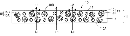
図1に示される光波長変換シート10は、入射する光のうち一部の光の波長を他の波長に変換し、入射した光の他の一部および波長変換された光を出射させるシートである。光波長変換シート10は、単層構造となっている。すなわち、光波長変換シート10は、光波長変換層11のみからなり、光波長変換シート10はバリアフィルムを備えていない。
<<< Light wavelength conversion sheet >>>
The light
光波長変換シート10は、シート全体で、40℃、相対湿度90%での水蒸気透過率(WVTR:Water Vaper Transmission Rate)が0.1g/(m2・24h)以上および/または23℃、相対湿度90%での酸素透過率(OTR: Oxygen Transmission Rate)が0.1cm3/(m2・24h・atm)以上となっている。
The light
水蒸気透過率はJIS K7129に準拠した手法で得られる数値である。水蒸気透過率は、水蒸気透過率測定装置(製品名「DELTAPERM」(Technolox社製)、製品名「PERMATRAN−W3/31」(MOCON社製))を用いて測定することができる。酸素透過率はJIS K7126に準拠した手法で得られる数値である。酸素透過率は、酸素ガス透過率測定装置(製品名「OX−TRAN 2/20」、「OX−TRAN 2/21」、いずれもMOCON社製)を用いて測定することができる。従来の光波長変換シートはバリアフィルムが形成されているので、光波長変換シート10は、従来の光波長変換シートに比べて水蒸気透過率および/または酸素透過率が高くなっている、すなわち、光波長変換シート10は、従来の光波長変換シートに比べて水分および/または酸素が透過しやすい。後述するように、光波長変換シートが、光波長変換層の他、光透過性基材や光学部材を備えている場合には、水蒸気透過率は光透過性基材や光学部材を含めた光波長変換シート全体での水蒸気透過率であり、酸素透過率は光透過性基材や光学部材を含めた光波長変換シート全体での酸素透過率である。ここで、本明細書における「バリアフィルム」とは、フィルム単体で、40℃、相対湿度90%での水蒸気透過率が0.1g/(m2・24h)未満となり、かつ23℃、相対湿度90%での酸素透過率が0.1cm3/(m2・24h・atm)未満となるフィルムを意味するものとする。バリアフィルムには、単層構造のフィルムのみならず、多層構造のフィルムも含まれる。
The water vapor transmission rate is a numerical value obtained by a method based on JIS K7129. The water vapor transmission rate can be measured using a water vapor transmission rate measuring device (product name “DELTAPERRM” (Technolox), product name “PERMATRAN-W3 / 31” (MOCON)). The oxygen transmission rate is a numerical value obtained by a method based on JIS K7126. The oxygen permeability can be measured using an oxygen gas permeability measuring device (product names “OX-TRAN 2/20” and “OX-TRAN 2/21”, both manufactured by MOCON). Since the conventional light wavelength conversion sheet is formed with a barrier film, the light
光波長変換シート10における40℃、相対湿度90%での水蒸気透過率は1g/(m2・24h)以上となっていてもよく、また光波長変換シート10における23℃、相対湿度90%での酸素透過率が1cm3/(m2・24h・atm)以上となっていてもよい。
In the light
光波長変換シート10を60℃、相対湿度90%の環境下に500時間放置する耐久性試験の前後において、光波長変換シート10の一方の表面10Aの全面に量子ドット15によって波長変換される所定の光量の光を照射して、光波長変換シート10の表面10Aとは反対側の面である他方の表面10Bの中央部から出射する光の輝度を測定したとき、耐久性試験前の光波長変換シート10の表面10Bの中央部から出射する光の輝度に対する耐久性試験後の光波長変換シート10の表面10Bの中央部から出射する光の輝度の変化率が±10%以内となっていることが好ましい。耐久性試験前の光波長変換シート10の表面10Bの中央部から出射する光の輝度に対する耐久性試験後の光波長変換シート10の表面10Bの中央部から出射する光の輝度の変化率は±5%以内であることが好ましい。
Before and after the durability test in which the light
光波長変換シートの一方の表面の全面に照射される光としては、量子ドットによって波長変換される光を含んでいれば、量子ドットによって波長変換されない光を含んでいてもよい。光波長変換層が、例えば、青色光を緑色光に変換する量子ドットおよび青色光を赤色光に変換する量子ドットの両方を含む場合には、量子ドットによって波長変換される光としては、青色光を用いることができる。上記で耐久性試験の前後において光波長変換シートに所定の光量の光を照射するとしたのは、耐久性試験の前後において異なる光量の光を光波長変換シートに照射すると、正確な輝度変化率が測定できないので、正確な輝度変化率を測定するために、耐久性試験の前後においてある一定の光量の光を光波長変換シートに照射するとした。 The light irradiated on the entire surface of the one surface of the light wavelength conversion sheet may include light that is not wavelength-converted by the quantum dots as long as it includes light that is wavelength-converted by the quantum dots. When the light wavelength conversion layer includes, for example, both a quantum dot that converts blue light into green light and a quantum dot that converts blue light into red light, the light that is wavelength-converted by the quantum dot is blue light. Can be used. The reason for irradiating the light wavelength conversion sheet with a predetermined amount of light before and after the durability test is that when the light wavelength conversion sheet is irradiated with different amounts of light before and after the durability test, an accurate luminance change rate is obtained. Since it was not possible to measure, in order to measure an accurate luminance change rate, the light wavelength conversion sheet was irradiated with a certain amount of light before and after the durability test.
耐久性試験の前後における輝度変化率は、輝度変化率をAとし、耐湿熱性試験前の光波長変換シート10の表面10Bの中央部から出射する光の輝度をBとし、耐湿熱性試験後の光波長変換シート10の表面10Bの中央部から出射する光の輝度をCとしたとき、下記式によって求めることができる。
A=(C−B)/B×100
The luminance change rate before and after the durability test is A, the luminance change rate is A, the luminance of light emitted from the central portion of the
A = (C−B) / B × 100
耐湿熱性試験の前後における輝度は、光波長変換シートの他方の表面の中央部から出射する光を、光波長変換シートの厚み方向から、分光放射輝度計(製品名「CS2000」、コニカミノルタ社製)を用いて、測定角1°の条件で、測定される。 The luminance before and after the wet heat resistance test is determined by measuring the light emitted from the center of the other surface of the light wavelength conversion sheet from the thickness direction of the light wavelength conversion sheet (product name “CS2000”, manufactured by Konica Minolta, Inc.). ) Is measured under the condition of a measurement angle of 1 °.
光波長変換シートの他方の表面の中央部から出射する光の輝度は、光波長変換シートの他方の表面の中央部から出射する光の輝度を直接的または間接的に測定することによって得ることが可能である。すなわち、光波長変換シートの他方の表面の中央部から出射する光の輝度を直接測定することによって得てもよいが、光波長変換シートを光源およびレンズシート等を備えたバックライト装置に組み込み、光波長変換シートの他方の表面の中央部を介してバックライト装置の発光面の中央部から出射する光の輝度を測定することによって得てもよい。ただし、耐久性試験前の輝度の測定と耐久性試験後の輝度の測定は、同条件によって行うことは言うまでもない。 The brightness of the light emitted from the center of the other surface of the light wavelength conversion sheet can be obtained by directly or indirectly measuring the brightness of the light emitted from the center of the other surface of the light wavelength conversion sheet. Is possible. That is, it may be obtained by directly measuring the luminance of the light emitted from the center of the other surface of the light wavelength conversion sheet, but the light wavelength conversion sheet is incorporated into a backlight device including a light source and a lens sheet, You may obtain by measuring the brightness | luminance of the light radiate | emitted from the center part of the light emission surface of a backlight apparatus through the center part of the other surface of a light wavelength conversion sheet. However, it goes without saying that the luminance measurement before the durability test and the luminance measurement after the durability test are performed under the same conditions.
光波長変換シート10において、60℃、相対湿度90%の環境下に500時間放置する耐久性試験を行ったとき、耐久性試験後の光波長変換シート10における周縁部の劣化幅が5mm以下となることが好ましく、3mm以下となることがより好ましい。ここで、光波長変換シートの周縁部の劣化幅は、以下のようにして求めるものとする。まず、耐久性試験後の光波長変換シートをバックライト装置に組み込み、バックライト装置の点灯時の発光面における輝度分布を、光波長変換シートの厚み方向から、2D色彩輝度計(製品名「UA−200」、トプコンテクノハウス社製)を用いて、測定する。そして、測定した発光面の輝度分布から、発光面の中央部の輝度に対して輝度が80%となる位置(以下、この位置を「輝度80%位置」と称する。)を求め、発光面における輝度80%位置に最も近い端から輝度80%位置までの最短距離を求める。そして、この最短距離をランダムに20箇所について求め、20箇所の最短距離の平均値を、光波長変換シートの周縁部の劣化幅とする。
In the light
光波長変換シート10の膜厚は、10μm以上150μm以下となっていることが好ましい。光波長変換シート10の膜厚がこの範囲であれば、バックライト装置の軽量化および薄膜化に適している。
The film thickness of the light
光波長変換シート10の膜厚は、走査型電子顕微鏡(SEM)、透過型電子顕微鏡(TEM)又は走査透過型電子顕微鏡(STEM)を用いて光波長変換シートの断面を撮影し、その断面の画像において光波長変換シートの膜厚を20箇所測定し、その20箇所の膜厚の平均値とする。これらの中でも、光波長変換シート10の膜厚がμmオーダーであることを考慮すると、SEMを用いることが好ましい。SEMの場合、加速電圧は30kV、倍率は1000〜7000倍とすることが好ましく、TEM又はSTEMの場合、加速電圧は30kV、倍率は5万〜30万倍とすることが好ましい。
The film thickness of the light
光波長変換シート10の少なくとも一方の面は、光波長変換シート10と他の部材との貼り付きを防止するために、算術平均粗さ(Ra)が0.1μm以上の凹凸面となっていることが好ましい。凹凸面は賦形処理によって形成することが可能であるが、アンチブロッキング剤を光波長変換シート10に含ませることによっても形成することが可能である。
At least one surface of the light
光波長変換層11は、例えば、バインダ樹脂12と、バインダ樹脂12に分散された光波長変換粒子13とを含んでいる。なお、本実施形態では、光波長変換層は、バインダ樹脂12および光波長変換粒子13を含んでいるが、バインダ樹脂および量子ドットを含んでいればよく、光波長変換粒子を含んでいなくともよい。また、光波長変換シートまたは光波長変換層は、光散乱性粒子14やアンチブロッキング剤(図示せず)をさらに含んでいてもよい。本明細書においては、「光散乱」という用語は、光波長変換シートの内部における粒子に起因する光散乱を意味する。
The light
光波長変換層11は、後述する量子ドット15の劣化抑制機能を有している。光波長変換層11に量子ドット15の劣化抑制機能を付与する手段としては、特に限定されないが、本実施形態のようにバリア粒子によって量子ドットを包むこと、または第2の実施形態のように蛍光X線分析により測定される光波長変換層中の硫黄、リン、および窒素からなる群から選択される1種以上の元素の含有量を0.5質量%以上にすることが挙げられる。
The light
シート全体で、40℃、相対湿度90%での水蒸気透過率が0.1g/(m2・24h)以上および/または23℃、相対湿度90%での酸素透過率が0.1cm3/(m2・24h・atm)以上となっている光波長変換シートにおいては、光波長変換層11が量子ドット15の劣化抑制機能を有しているか否かは、以下のように判断するものとする。まず、光波長変換シートを60℃、相対湿度90%の環境下に100時間放置する耐劣化性試験前の光波長変換シートの一方の表面の全面に量子ドットによって波長変換される所定の光量の光を照射して、光波長変換シートの表面とは反対側の面である他方の表面の中央部から出射する光の輝度を測定する。輝度は、光波長変換シートの他方の表面の中央部から出射する光を、光波長変換シートの厚み方向から、分光放射輝度計(製品名「CS2000」、コニカミノルタ社製)を用いて、測定角1°の条件で、測定される。次いで、光波長変換シートに、上記耐劣化性試験を行い、その後上記と同様の条件で、耐劣化性試験後の光波長変換シートの他方の表面の中央部から出射する光の輝度を測定する。そして、耐劣化性試験前の光波長変換シートの中央部から出射する光の輝度に対する耐劣化性試験後の光波長変換シートの中央部から出射する光の輝度の変化率を求める。そして、この輝度変化率が±10%以内となっていれば、光波長変換層が量子ドットの劣化抑制機能を有していると判断する。
The entire sheet has a water vapor transmission rate of 0.1 g / (m 2 · 24 h) or more at 40 ° C. and a relative humidity of 90% and / or an oxygen transmission rate of 0.1 cm 3 / (23 ° C. and a relative humidity of 90%. m 2 · 24h · atm) In the light wavelength conversion sheet that is equal to or greater than, whether or not the light
耐劣化性試験の前後における輝度変化率は、輝度変化率をDとし、耐劣化性試験前の光波長変換シートの中央部から出射する光の輝度をEとし、耐劣化性試験後の光波長変換シートの中央部から出射する光の輝度をFとしたとき、下記式によって求めるものとする。
D=(F−E)/E×100
The luminance change rate before and after the deterioration resistance test is set to D, the luminance of light emitted from the central portion of the light wavelength conversion sheet before the deterioration resistance test as E, and the light wavelength after the deterioration resistance test. When the luminance of the light emitted from the central portion of the conversion sheet is F, the following formula is used.
D = (F−E) / E × 100
上記においては、光波長変換層が量子ドットの劣化抑制機能を有しているか否かの判断を、光波長変換シート全体における耐劣化性試験前後の輝度変化率から行っている。すなわち、光波長変換層の少なくとも一方の面に何らかの基材やフィルム等が設けられた光波長変換シートであっても、光波長変換層からこの基材やフィルム等を剥離することなしに、光波長変換層の面にこの基材やフィルム等が設けられた光波長変換シート全体での輝度変化率から、光波長変換層が量子ドットの劣化抑制機能を有しているか否かの判断を行う。これは、以下の理由からである。まず、シート全体で、40℃、相対湿度90%での水蒸気透過率が0.1g/(m2・24h)以上および/または23℃、相対湿度90%での酸素透過率が0.1cm3/(m2・24h・atm)以上となっている光波長変換シートにおいては、水蒸気透過率および/または酸素透過率が高いので、何らかの対策を採らない限り、水分や酸素によって量子ドットが劣化してしまう。ここで、仮に光波長変換層の少なくとも一方の面に何らかの基材やフィルム等が設けられていたとしても、上記のような高い水蒸気透過率や酸素透過率を有する光波長変換シートにおいては、この基材やフィルム等も高い水蒸気透過率や酸素透過率を有するので、この基材やフィルム等によって、量子ドットの劣化を抑制することはできない。したがって、このような高い水蒸気透過率や酸素透過率を有する光波長変換シートにおいて、耐劣化性試験前後での輝度変化率が±10%以内であった場合、基材やフィルム等によって量子ドットの劣化が抑制されたのではなく、光波長変換層によって量子ドットの劣化が抑制されたので、輝度変化率を±10%以内となったと考えることができる。このため、光波長変換層単体から構成された光波長変換シートのみならず、光波長変換層の少なくとも一方の面に基材やフィルム等が設けられた光波長変換シートにおける耐劣化性試験前後の輝度変化率は、量子ドットの劣化抑制機能の有無を判断する指標として捉えることができる。したがって、たとえ、光波長変換層の少なくとも一方の面に基材やフィルム等が設けられた光波長変換シートであっても、光波長変換シートにおける耐劣化性試験前後の輝度変化率から、光波長変換層が量子ドットの劣化抑制機能を有しているか否かの判断をすることとした。 In the above description, whether or not the light wavelength conversion layer has the function of suppressing deterioration of quantum dots is determined from the luminance change rate before and after the deterioration resistance test in the entire light wavelength conversion sheet. That is, even in the case of an optical wavelength conversion sheet in which some substrate or film is provided on at least one surface of the optical wavelength conversion layer, the optical wavelength conversion layer can be used without peeling the substrate or film from the optical wavelength conversion layer. Judgment is made as to whether or not the light wavelength conversion layer has a function of suppressing deterioration of quantum dots from the luminance change rate of the entire light wavelength conversion sheet in which the base material, film, etc. are provided on the surface of the wavelength conversion layer . This is for the following reason. First, the entire sheet has a water vapor transmission rate of 0.1 g / (m 2 · 24 h) or more at 40 ° C. and a relative humidity of 90% and / or an oxygen transmission rate of 0.1 cm 3 at 23 ° C. and a relative humidity of 90%. / (M 2 · 24h · atm) or more, the light wavelength conversion sheet has a high water vapor transmission rate and / or oxygen transmission rate. Therefore, unless some measures are taken, the quantum dots deteriorate due to moisture and oxygen. End up. Here, even if some substrate or film is provided on at least one surface of the light wavelength conversion layer, in the light wavelength conversion sheet having a high water vapor transmission rate and oxygen transmission rate as described above, Since the base material and the film also have high water vapor transmission rate and oxygen transmission rate, the deterioration of the quantum dots cannot be suppressed by this base material or film. Therefore, in the light wavelength conversion sheet having such a high water vapor transmission rate and oxygen transmission rate, when the luminance change rate before and after the deterioration resistance test is within ± 10%, the quantum dots of the base material, film, etc. Since the deterioration of the quantum dots was suppressed by the light wavelength conversion layer, not the deterioration, it can be considered that the luminance change rate was within ± 10%. For this reason, before and after the deterioration resistance test in the light wavelength conversion sheet in which the substrate or film is provided on at least one surface of the light wavelength conversion layer as well as the light wavelength conversion sheet composed of the light wavelength conversion layer alone. The luminance change rate can be regarded as an index for determining the presence / absence of a function of suppressing deterioration of quantum dots. Therefore, even if it is a light wavelength conversion sheet in which a base material, a film, etc. are provided on at least one surface of the light wavelength conversion layer, the light wavelength is calculated from the luminance change rate before and after the deterioration resistance test in the light wavelength conversion sheet. It was decided whether or not the conversion layer had a function of suppressing deterioration of quantum dots.
耐劣化性試験における光波長変換シートの他方の表面の中央部から出射する光の輝度は、光波長変換シートの他方の表面の中央部から出射する光の輝度を直接的または間接的に測定することによって得ることが可能である。すなわち、光波長変換シートの他方の表面の中央部から出射する光の輝度を直接測定することによって得てもよいが、光波長変換シートを光源およびレンズシート等を備えたバックライト装置に組み込み、光波長変換シートの他方の表面の中央部を介してバックライト装置の発光面の中央部から出射する光の輝度を測定することによって得てもよい。 The brightness of light emitted from the center of the other surface of the light wavelength conversion sheet in the degradation resistance test is measured directly or indirectly by the brightness of light emitted from the center of the other surface of the light wavelength conversion sheet. Can be obtained. That is, it may be obtained by directly measuring the luminance of the light emitted from the center of the other surface of the light wavelength conversion sheet, but the light wavelength conversion sheet is incorporated into a backlight device including a light source and a lens sheet, You may obtain by measuring the brightness | luminance of the light radiate | emitted from the center part of the light emission surface of a backlight apparatus through the center part of the other surface of a light wavelength conversion sheet.
<<バインダ樹脂>>
バインダ樹脂12としては、特に限定されないが、硬化性バインダ樹脂前駆体の硬化物(重合物、架橋物)が挙げられる。本明細書における「硬化性バインダ樹脂前駆体」とは、硬化することによってバインダ樹脂の成分となる化合物を意味する。硬化性バインダ樹脂前駆体としては、重合性化合物(硬化性化合物)が挙げられる。重合性化合物は、重合可能な化合物であり、例えば、電離放射線重合性化合物(電離放射線硬化性化合物)および/または熱重合性化合物(熱硬化性化合物)が挙げられる。
<< Binder resin >>
Although it does not specifically limit as
<電離放射線重合性化合物>
電離放射線重合性化合物は、分子内に電離放射線重合性官能基を少なくとも1つ有するものである。本明細書における、「電離放射線重合性官能基」とは、電離放射線照射により重合反応し得る官能基である。電離放射線重合性官能基としては、例えば、(メタ)アクリロイル基、ビニル基、アリル基等のエチレン性二重結合が挙げられる。なお、「(メタ)アクリロイル基」とは、「アクリロイル基」および「メタクリロイル基」の両方を含む意味である。また、光重合性化合物を重合する際に照射される電離放射線としては、可視光線、並びに紫外線、X線、電子線、α線、β線、およびγ線が挙げられる。
<Ionizing radiation polymerizable compound>
The ionizing radiation polymerizable compound has at least one ionizing radiation polymerizable functional group in the molecule. In the present specification, the “ionizing radiation polymerizable functional group” is a functional group capable of undergoing a polymerization reaction upon irradiation with ionizing radiation. Examples of the ionizing radiation polymerizable functional group include ethylenic double bonds such as a (meth) acryloyl group, a vinyl group, and an allyl group. The “(meth) acryloyl group” means to include both “acryloyl group” and “methacryloyl group”. Examples of the ionizing radiation irradiated when polymerizing the photopolymerizable compound include visible light, ultraviolet rays, X-rays, electron beams, α rays, β rays, and γ rays.
電離放射線重合性化合物としては、電離放射線重合性モノマー、電離放射線重合性オリゴマー、または電離放射線重合性プレポリマーが挙げられ、これらを適宜調整して、用いることができる。電離放射線重合性化合物としては、電離放射線重合性モノマーと、電離放射線重合性オリゴマーまたは電離放射線重合性プレポリマーとの組み合わせが好ましい。 Examples of the ionizing radiation polymerizable compound include an ionizing radiation polymerizable monomer, an ionizing radiation polymerizable oligomer, and an ionizing radiation polymerizable prepolymer, and these can be appropriately adjusted and used. As the ionizing radiation polymerizable compound, a combination of an ionizing radiation polymerizable monomer and an ionizing radiation polymerizable oligomer or an ionizing radiation polymerizable prepolymer is preferable.
光重合性モノマーは、重量平均分子量が1000以下のものである。光重合性モノマーとしては、例えば、2−ヒドロキシエチル(メタ)アクリレート、2−ヒドロキシプロピル(メタ)アクリレート、2−エチルヘキシル(メタ)アクリレート等の水酸基を含むモノマーや、エチレングリコールジ(メタ)アクリレート、ジエチレングリコールジ(メタ)アクリレート、トリエチレングリコールジ(メタ)アクリレート、テトラエチレングリコールジ(メタ)アクリレート、テトラメチレングリコールジ(メタ)アクリレート、トリメチロールプロパントリ(メタ)アクリレート、トリメチロールエタントリ(メタ)アクリレート、ペンタエリスリトールジ(メタ)アクリレート、ペンタエリスリトールトリ(メタ)アクリレート、ペンタエリスリトールテトラ(メタ)アクリレート、ジペンタエリスリトールテトラ(メタ)アクリレート、ジペンタエリスリトールヘキサ(メタ)アクリレート、グリセロール(メタ)アクリレート等の(メタ)アクリル酸エステル類が挙げられる。 The photopolymerizable monomer has a weight average molecular weight of 1000 or less. Examples of the photopolymerizable monomer include monomers containing a hydroxyl group such as 2-hydroxyethyl (meth) acrylate, 2-hydroxypropyl (meth) acrylate, 2-ethylhexyl (meth) acrylate, ethylene glycol di (meth) acrylate, Diethylene glycol di (meth) acrylate, triethylene glycol di (meth) acrylate, tetraethylene glycol di (meth) acrylate, tetramethylene glycol di (meth) acrylate, trimethylolpropane tri (meth) acrylate, trimethylolethane tri (meth) Acrylate, pentaerythritol di (meth) acrylate, pentaerythritol tri (meth) acrylate, pentaerythritol tetra (meth) acrylate, dipentaerythritol Tetra (meth) acrylate, dipentaerythritol hexa (meth) acrylate, glycerol (meth) (meth) acrylic acid esters such as acrylate.
光重合性オリゴマーは、重量平均分子量が1000を超え10000以下のものである。上記光重合性オリゴマーとしては、2官能以上の多官能オリゴマーが好ましく、光重合性官能基が3つ(3官能)以上の多官能オリゴマーが好ましい。上記多官能オリゴマーとしては、例えば、ポリエステル(メタ)アクリレート、ウレタン(メタ)アクリレート、ポリエステル−ウレタン(メタ)アクリレート、ポリエーテル(メタ)アクリレート、ポリオール(メタ)アクリレート、メラミン(メタ)アクリレート、イソシアヌレート(メタ)アクリレート、エポキシ(メタ)アクリレート等が挙げられる。 The photopolymerizable oligomer has a weight average molecular weight of more than 1000 and 10,000 or less. As the photopolymerizable oligomer, a polyfunctional oligomer having two or more functions is preferable, and a polyfunctional oligomer having three (trifunctional) or more photopolymerizable functional groups is preferable. Examples of the polyfunctional oligomer include polyester (meth) acrylate, urethane (meth) acrylate, polyester-urethane (meth) acrylate, polyether (meth) acrylate, polyol (meth) acrylate, melamine (meth) acrylate, and isocyanurate. (Meth) acrylate, epoxy (meth) acrylate, etc. are mentioned.
光重合性プレポリマーは、重量平均分子量が1万を超えるものであり、重量平均分子量としては1万以上8万以下が好ましく、1万以上4万以下がより好ましい。重量平均分子量が8万を超える場合は、粘度が高いため塗工適性が低下してしまい、得られる光波長変換層の外観が悪化するおそれがある。多官能プレポリマーとしては、ウレタン(メタ)アクリレート、イソシアヌレート(メタ)アクリレート、ポリエステル−ウレタン(メタ)アクリレート、エポキシ(メタ)アクリレート等が挙げられる。 The photopolymerizable prepolymer has a weight average molecular weight exceeding 10,000, and the weight average molecular weight is preferably from 10,000 to 80,000, and more preferably from 10,000 to 40,000. When the weight average molecular weight exceeds 80,000, the viscosity is high, so that the coating suitability is lowered, and the appearance of the obtained light wavelength conversion layer may be deteriorated. Examples of the polyfunctional prepolymer include urethane (meth) acrylate, isocyanurate (meth) acrylate, polyester-urethane (meth) acrylate, and epoxy (meth) acrylate.
<熱重合性化合物>
熱重合性化合物は、分子内に熱重合性官能基を少なくとも1つ有するものである。熱重合性官能基としては、例えば、エポキシ基やオキセタニル基等の環状エーテル基、ビニルエーテル基、イソシアネート基、グリシジル基、水酸基、カルボキシル基、アミノ基、アミド基等が挙げられる。
<Thermopolymerizable compound>
The thermopolymerizable compound has at least one thermopolymerizable functional group in the molecule. Examples of the thermally polymerizable functional group include cyclic ether groups such as epoxy groups and oxetanyl groups, vinyl ether groups, isocyanate groups, glycidyl groups, hydroxyl groups, carboxyl groups, amino groups, and amide groups.
熱重合性化合物としては、特に限定されず、例えば、フェノール化合物、尿素化合物、ジアリルフタレート化合物、メラミン化合物、グアナミン化合物、不飽和ポリエステル化合物、ウレタン化合物、エポキシ化合物、アミノアルキッド化合物、メラミン−尿素共縮合化合物、ケイ素化合物、ポリシロキサン化合物等が挙げられる。熱硬化性樹脂は、1種単独で使用してもよく、また2種以上を組み合わせて使用してもよい。これらの中でも、硬化性や耐熱性の観点から、エポキシ化合物やウレタン化合物が好ましい。熱重合性化合物は、熱重合性モノマー、熱重合性オリゴマー、熱重合性樹脂(プレポリマー)、またはこれらの混合物であってもよい。 The thermopolymerizable compound is not particularly limited, and examples thereof include phenol compounds, urea compounds, diallyl phthalate compounds, melamine compounds, guanamine compounds, unsaturated polyester compounds, urethane compounds, epoxy compounds, aminoalkyd compounds, and melamine-urea cocondensation. A compound, a silicon compound, a polysiloxane compound, etc. are mentioned. A thermosetting resin may be used individually by 1 type, and may be used in combination of 2 or more type. Among these, an epoxy compound and a urethane compound are preferable from the viewpoints of curability and heat resistance. The thermopolymerizable compound may be a thermopolymerizable monomer, a thermopolymerizable oligomer, a thermopolymerizable resin (prepolymer), or a mixture thereof.
エポキシ化合物としては、一分子中にエポキシ基を有するものであれば特に制限はなく、例えば、ビスフェノールA型エポキシ化合物、ビスフェノールF型エポキシ化合物、臭素化ビスフェノールA型エポキシ化合物、ビスフェノールS型エポキシ化合物、ジフェニルエーテル型エポキシ化合物、ハイドロキノン型エポキシ化合物、ナフタレン型エポキシ化合物、ビフェニル型エポキシ化合物、フルオレン型エポキシ化合物、フェノールノボラック型エポキシ化合物、オルソクレゾールノボラック型エポキシ化合物、トリスヒドロキシフェニルメタン型エポキシ化合物、3官能型エポキシ化合物、テトラフェニロールエタン型エポキシ化合物、ジシクロペンタジエンフェノール型エポキシ化合物、水添ビスフェノールA型エポキシ化合物、ビスフェノールA含核ポリオール型エポキシ化合物、ポリプロピレングリコール型エポキシ化合物、グリシジルエステル型エポキシ化合物、グリシジルアミン型エポキシ化合物、グリオキザール型エポキシ化合物、脂環型エポキシ化合物、複素環型エポキシ化合物などを使用できる。エポキシ化合物は、モノマーであってもよく、また樹脂であってもよい。 The epoxy compound is not particularly limited as long as it has an epoxy group in one molecule. For example, bisphenol A type epoxy compound, bisphenol F type epoxy compound, brominated bisphenol A type epoxy compound, bisphenol S type epoxy compound, Diphenyl ether type epoxy compound, hydroquinone type epoxy compound, naphthalene type epoxy compound, biphenyl type epoxy compound, fluorene type epoxy compound, phenol novolac type epoxy compound, orthocresol novolac type epoxy compound, trishydroxyphenylmethane type epoxy compound, trifunctional type epoxy Compound, tetraphenylolethane type epoxy compound, dicyclopentadienephenol type epoxy compound, hydrogenated bisphenol A type epoxy compound, Phenol A 含核 polyol type epoxy compounds, polypropylene glycol type epoxy compounds, glycidyl ester type epoxy compounds, glycidyl amine type epoxy compounds, glyoxal type epoxy compounds, alicyclic epoxy compounds, heterocyclic epoxy compounds and the like can be used. The epoxy compound may be a monomer or a resin.
後述するバリア粒子16が無機酸化物粒子である場合には、バリア粒子16の表面には水酸基が存在し、またはシランカップリング剤による表面修飾によってメルカプト基、(メタ)アクリロイル基、ビニル基、スチリル基、エポキシ基、イソシアネート基、アミノ基からなる群から選択される1種以上の基が存在することもあるので、硬化性バインダ樹脂前駆体としては、水酸基やメルカプト基等と反応する官能基を有していることが好ましい。このような官能基としては、例えば、エポキシ基、イソシアネート基、メルカプト基、(メタ)アクリロイル基、ビニル基、およびアリル基等が挙げられる。
When the
<<光波長変換粒子>>
光波長変換粒子13は、光の波長変換を行う量子ドット15と、量子ドット15を包み、かつ水分および酸素の透過を抑制する光透過性のバリア粒子16とを含んでいる。量子ドット15とバリア粒子16との間には空気層は存在せず、量子ドット15の表面はバリア粒子16に密着している。
<< Light wavelength conversion particle >>
The light
図2に示されるように、光波長変換シート10の入光面10Aから光を入射させた場合には、量子ドット15に入射した光L1は光L1とは異なる波長の光L2に変換されて、入光面10Aとは反対側の面である出光面10Bから出射する。一方、入光面10Aから光を入射させた場合であっても、量子ドット15間を通過する光L1は波長変換されずに、出光面10Bから出射する。
As shown in FIG. 2, when light is incident from the
光波長変換粒子13は、1個あたり1個以上50個以下の量子ドット15を含んでいることが好ましく、1個あたり1個以上40個以下または1個以上35個以下の量子ドット15を含んでいることがより好ましい。光波長変換粒子1個に含まれる量子ドットの数が1個を下回ると、輝度が低くなるおそれがあり、また光波長変換粒子1個に含まれる量子ドットの数が50個を上回ると、量子ドット間のエネルギー移動に起因してクエンチングを起こす濃度消光により、発光効率が低下するおそれがある。1個の光波長変換粒子に含まれる量子ドットの個数は、透過型電子顕微鏡(TEM)または走査透過型電子顕微鏡(STEM)を用いてランダムに20個の光波長変換粒子の断面を10万倍〜50万倍の倍率で撮影し、得られた断面の画像から1個の光波長変換粒子に含まれる量子ドットの個数を算出し、算出した量子ドットの個数の平均値を算出することで求めることができる。
The light
光波長変換粒子13は、1個あたり2個以上の量子ドット15を含んでおり、かつ1個の光波長変換粒子13に含まれる量子ドット15における量子ドット15間の平均距離が1nm以上であることが好ましい。量子ドット間の平均距離が1nm未満であると、量子ドット間のエネルギー移動が起こり易く、発光効率が低下するおそれがある。量子ドット間の平均距離は、透過型電子顕微鏡または走査透過型電子顕微鏡を用いてランダムに20個の光波長変換粒子の断面を10万倍〜50万倍の倍率で撮影し、得られた断面の画像から量子ドット間の距離を算出し、算出した量子ドット間の距離の平均値を算出することで求めることができる。量子ドット15における量子ドット15間の平均距離の上限は100nm以下であることがより好ましい。
The light
光波長変換粒子13の平均粒子径は、10nm以上500nm以下であることが好ましい。光波長変換粒子の平均粒子径が、10nm未満であると、量子ドットに対し充分にバリア性を付与することができず、量子ドットが酸化劣化等を起こすおそれがあり、また500nmを超えると、理由は定かではないがバリア粒子のバリア性が不安定になるおそれがある。光波長変換粒子の平均粒子径は、透過型電子顕微鏡または走査透過型電子顕微鏡による光波長変換シートの断面観察において光波長変換粒子20個の粒子径を測定し、その平均値を算出することで求めることができる。光波長変換粒子13の平均粒子径の下限は、20nm以上であることが好ましく、光波長変換粒子13の平均粒子径の上限は200nm以下であることが好ましく、100nm以下であることがより好ましい。
The average particle diameter of the light
<量子ドット>
量子ドット15は、量子閉じ込め効果(quantum confinement effect)を有するナノサイズの半導体粒子である。量子ドット15の粒子径および平均粒子径は、例えば、1nm以上20nm以下となっている。量子ドット15は、励起源から光を吸収してエネルギー励起状態に達すると、量子ドット15のエネルギーバンドギャップに該当するエネルギーを放出する。よって、量子ドット15の粒子径又は物質の組成を調節すると、エネルギーバンドギャップを調節することができ、様々なレベルの波長帯のエネルギーを得ることができる。とりわけ、量子ドット15は、狭い波長帯で強い蛍光を発生することができる。
<Quantum dots>
The
具体的には、量子ドット15は粒子径が小さくなるに従い、エネルギーバンドギャップが大きくなる。すなわち、結晶サイズが小さくなるにつれて、量子ドットの発光は青色側へ、つまり、高エネルギー側へとシフトする。そのため、量子ドットの粒子径を変化させることにより、紫外領域、可視領域、赤外領域のスペクトルの波長全域にわたって、その発光波長を調節することができる。例えば、量子ドットが後述するCdSe/ZnSから構成されている場合には、量子ドットの粒子径が2.0nm以上4.0nm以下の場合は青色光を発し、量子ドットの粒子径が3.0nm以上6.0nm以下の場合は緑色光を発し、量子ドットの粒子径が4.5nm以上10.0nm以下の場合は赤色光を発する。なお、上記においては、青色光を発する量子ドットの粒子径と緑色光を発する量子ドットの粒子径の範囲は一部において重複しており、また緑色光を発する量子ドットの粒子径と赤色光を発する量子ドットの粒子径の範囲は一部において重複しているが、同じ粒子径を有する量子ドットであっても、量子ドットのシェルの厚みによっても発光色が異なる場合があるので、何ら矛盾するものではない。
Specifically, the energy band gap of the
本明細書における「青色光」とは、380nm以上480nm未満の波長域を有する光であり、「緑色光」とは、480nm以上590nm未満の波長域を有する光であり、「赤色光」とは、590nm以上750nm以下の波長域を有する光である。 In this specification, “blue light” is light having a wavelength range of 380 nm or more and less than 480 nm, “green light” is light having a wavelength range of 480 nm or more and less than 590 nm, and “red light” is It is light having a wavelength range of 590 nm to 750 nm.
量子ドット15としては、1種類の量子ドットを用いてもよいが、粒子径または材料等が異なることにより、それぞれ単独の波長域の発光帯を有する2種類以上の量子ドットを用いることも可能である。光波長変換シート10は、図1に示されるように、量子ドット15として、第1の量子ドット15Aと、第1の量子ドット15Aとは異なる波長域の発光帯を有する第2の量子ドット15Bとを含んでいる。
Although one kind of quantum dot may be used as the
量子ドットとして、それぞれ単独の波長域の発光帯を有する2種以上の量子ドットを用いる場合、光波長変換粒子1個あたり2種類以上の量子ドットを含んでいてもよく、また光波長変換粒子1個あたり1種類の量子ドットを含んでいてもよい。なお、青色光を緑色光に変換する量子ドットと、青色光を赤色光に変換する量子ドットとを1個の光波長変換粒子の中に含ませた場合には、青色光を緑色光に変換する量子ドットによって発生する緑色光が、青色光を赤色光に変換する量子ドットによって吸収されてしまう場合もあるので、この場合には、1個の光波長変換粒子の中に1種類の量子ドットのみを含ませることが好ましい。 When two or more types of quantum dots each having an emission band in a single wavelength range are used as the quantum dots, two or more types of quantum dots may be included per one light wavelength conversion particle, and the light wavelength conversion particle 1 One type of quantum dot may be included per unit. In addition, when a quantum dot that converts blue light into green light and a quantum dot that converts blue light into red light are included in one light wavelength conversion particle, blue light is converted into green light. Since the green light generated by the quantum dots that are generated may be absorbed by the quantum dots that convert blue light into red light, in this case, one kind of quantum dot is included in one light wavelength conversion particle. It is preferable to include only.
上記したように光波長変換シート10から出射される光としては波長変換されない光も存在するので、光源として青色光を発する光源を用い、第1の量子ドット15Aとして青色光を緑色光に変換する量子ドットを用い、第2の量子ドット15Bとして青色光を赤色光に変換する量子ドットを用いた場合には、光波長変換シート10から、青色光、緑色光、赤色光が混合した光を出射させることができる。
As described above, since there is also light that is not wavelength-converted as light emitted from the light
量子ドット15は、所望の狭い波長域で強い蛍光を発生することができる。このため、光波長変換シート10を用いたバックライト装置は、色純度の優れた三原色の光で、表示パネルを照明することができる。この場合、表示パネルは、優れた色再現性を有することになる。
The
量子ドット15は、主に、約2nm以上10nm以下の半導体化合物からなるコアと、このコアと異なる半導体化合物からなるシェルとを有するコアシェル型構造を有していてもよい。シェルはコアを保護する保護層としての機能を有する。
The
コアとなる材料としては、例えば、MgS、MgSe、MgTe、CaS、CaSe、CaTe、SrS、SrSe、SrTe、BaS、BaSe、BaTe、ZnS、ZnSe、ZnTe、CdS、CdSe、CdTe、HgS、HgSe及びHgTeのようなII−VI族半導体化合物、AlN、AlP、AlAs、AlSb、GaAs、GaP、GaN、GaSb、InN、InAs、InP、InSb、TiN、TiP、TiAs及びTiSbのようなIII−V族半導体化合物、Si、Ge及びPbのようなIV族半導体、等の半導体化合物又は半導体を含有する半導体結晶が挙げられる。また、InGaPのような3元素以上を含んだ半導体化合物を含む半導体結晶を用いることもできる。これらの中でも、作製の容易性、可視域での発光を得られる粒子径の制御性等の観点から、CdS、CdSe、CdTe、InP、InGaP等の半導体結晶が好適である。 Examples of the core material include MgS, MgSe, MgTe, CaS, CaSe, CaTe, SrS, SrSe, SrTe, BaS, BaSe, BaTe, ZnS, ZnSe, ZnTe, CdS, CdSe, CdTe, HgS, HgSe, and HgTe. II-VI group semiconductor compounds such as AlN, AlP, AlAs, AlSb, GaAs, GaP, GaN, GaSb, InN, InAs, InP, InSb, TiN, TiP, TiAs and TiSb , Semiconductor compounds such as group IV semiconductors such as Si, Ge and Pb, or semiconductor crystals containing semiconductors. Alternatively, a semiconductor crystal including a semiconductor compound containing three or more elements such as InGaP can be used. Among these, semiconductor crystals such as CdS, CdSe, CdTe, InP, and InGaP are preferable from the viewpoints of ease of production and controllability of particle diameters that can obtain light emission in the visible range.
シェルは、励起子がコアに閉じ込められるように、コアを形成する半導体化合物よりもバンドギャップの高い半導体化合物を用いることで、量子ドットの発光効率を高めることができる。このようなバンドギャップの大小関係を有するコアシェル構造(コア/シェル)としては、例えば、CdSe/ZnS、CdSe/ZnSe、CdSe/CdS、CdTe/CdS、InP/ZnS、Gap/ZnS、Si/ZnS、InN/GaN、InP/CdSSe、InP/ZnSeTe、InGaP/ZnSe、InGaP/ZnS、Si/AlP、InP/ZnSTe、InGaP/ZnSTe、InGaP/ZnSSe等が挙げられる。 The shell can increase the light emission efficiency of the quantum dots by using a semiconductor compound having a band gap higher than that of the semiconductor compound forming the core so that excitons are confined in the core. Examples of the core-shell structure (core / shell) having such a bandgap relationship include CdSe / ZnS, CdSe / ZnSe, CdSe / CdS, CdTe / CdS, InP / ZnS, Gap / ZnS, Si / ZnS, Examples include InN / GaN, InP / CdSSe, InP / ZnSeTe, InGaP / ZnSe, InGaP / ZnS, Si / AlP, InP / ZnSTe, InGaP / ZnSTe, and InGaP / ZnSSe.
量子ドット15の形状は特に限定されず、例えば、球状、棒状、円盤状、その他の形状であってもよい。量子ドット16の粒子径は、量子ドット15が球状でない場合、同体積を有する真球状の値とすることができる。
The shape of the
量子ドット15の粒子径、平均粒子径、形状、分散状態等の情報については、透過型電子顕微鏡または走査透過型電子顕微鏡により得ることができる。量子ドットの平均粒子径は、透過型電子顕微鏡または走査透過型電子顕微鏡による光波長変換層の断面観察により測定された20個の量子ドットの直径の平均値として求めることができる。また、量子ドットは粒子径によって発光色が変化するので、量子ドットの発光色の確認から量子ドットの粒子径を求めることも可能である。また、量子ドットの結晶構造、結晶子サイズについては、X線結晶回折(XRD)により知ることができる。さらには、紫外−可視(UV−Vis)吸収スペクトルによって、量子ドットの粒子径等に関する情報を得ることもできる。
Information such as the particle size, average particle size, shape, and dispersion state of the
<バリア粒子>
バリア粒子16は、量子ドット15を包み、光透過性を有し、かつ水分および酸素の透過を抑制するバリア性を有するものである。量子ドット15をバリア粒子16で包むことにより、量子ドット15が水分や酸素に接触することを抑制できるので、量子ドット15が水分や酸素によって劣化することを抑制できる。これにより、バリア層を設けなくとも量子ドット15の発光効率の低下を抑制できる。本明細書において、「光透過性」とは、光を透過させる性質を有することを意味し、「光透過性」には透明も含まれる。本発明においては量子ドットがバリア粒子で包まれているので、光波長変換シートから出射される量子ドットからの発光を確認することができれば、バリア粒子は光透過性を有すると言える。量子ドットの発光は蛍光光度計を用いて確認することができる。「バリア性」は、光波長変換シートにおいて、40℃、相対湿度90%環境下に300時間放置する耐久性試験を行い、耐久性試験前後における光波長変換シートの発光ピーク強度の低下率が10%以内であれば、バリア粒子はバリア性があると判断することができる。ただし、光波長変換シートを透過した光源からの光は、光波長変換シートの発光により生じた光ではないので、光波長変換シートを透過した光源からの光のピーク強度は光波長変換シートの発光ピーク強度には含めないものとする。また、光波長変換シートから出射される光の発光ピークが複数存在する場合において、「発光ピーク強度の低下率が10%以内である」とはそれぞれの発光ピークにおける強度の低下率が10%以内であることを意味する。耐久性試験前後における光波長変換シートの発光ピークの低下率をGとし、耐久試験前の光波長変換シートの発光ピーク強度をHとし、耐久試験後の光波長変換シートの発光ピーク強度をIとすると、耐久性試験前後における光波長変換シートの発光ピークの低下率(G)は、以下の式によって求められる。
G=(H−I)/H×100
<Barrier particles>
The
G = (HI) / H × 100
バリア粒子16の形成材料としては、光透過性を有し、かつバリア性が得られるものであれば特に限定されないが、例えば、無機酸化物が挙げられる。具体的には、上記無機酸化物としては、例えば、シリカ等の酸化ケイ素(SiOx)、アルミナ等の酸化アルミニウム(AlnOm)、酸化チタン(TiO2)、酸化イットリウム、酸化ホウ素(B2O3)、酸化カルシウム(CaO)、酸化窒化炭化ケイ素(SiOxNyCz)等が挙げられ、これらの中でも、酸素や水蒸気の透過性が低いという観点からガラス等のシリカまたはアルミナが好ましい。これらの材料は、単独で用いられてもよく2種以上を組み合わせて用いられてもよい。また、酸化物半導体を除く無機酸化物を用いることも可能である。
The material for forming the
量子ドット15がCdを含んでいる場合、量子ドット15に含まれるCdの溶出を防ぐために、バリア粒子16の厚み(量子ドットの表面からバリア粒子の外表面までの距離)が2nm以上であることが好ましく、4nm以上であることがより好ましい。光波長変換粒子13の平均粒子径が50nm程度である場合には、バリア粒子16の厚みは10nm以上とすることも可能である。また、光波長変換粒子13の平均粒子径が100nm程度である場合には、バリア粒子16の厚みは20nm以上とすることも可能である。バリア粒子の厚みは、透過型電子顕微鏡観察において量子ドットを含まない外側の部分として容易に測定できる。バリア粒子の周縁の位置によって厚みが異なる場合には、バリア粒子周縁全体の平均によりバリア粒子の厚みとする。
When the
バリア粒子16は、バインダ樹脂12との密着性を向上させる観点から、バインダ樹脂12と化学結合していることが好ましい。この化学結合は、シランカップリング剤で表面修飾されたバリア粒子16によって行うことが可能である。
The
シランカップリング剤としては、用いる硬化性バインダ樹脂前駆体の種類にもよるが、ビニル基、エポキシ基、スチリル基、メタクリル基、アクリル基、アミノ基、ウレイド基、メルカプト基、スルフィド基およびイソシアネート基からなる群から選択される1種以上の反応性官能基を有するものを使用することが可能である。硬化性バインダ樹脂前駆体として(メタ)アクリロイル基を有する化合物を用いる場合には、カップリング剤は、メルカプト基、(メタ)アクリロイル基、ビニル基およびスチリル基からなる群から選択される少なくとも1種の反応性官能基を有することが好ましい。また、硬化性バインダ樹脂前駆体としてエポキシ基、イソシアネート基、および水酸基からなる群から選択される少なくとも1種の基を有する化合物を用いる場合には、シランカップリング剤はエポキシ基、イソシアネート基、メルカプト基およびアミノ基からなる群から選択される少なくとも1種の反応性官能基を有することが好ましい。 The silane coupling agent depends on the type of curable binder resin precursor to be used, but vinyl group, epoxy group, styryl group, methacryl group, acrylic group, amino group, ureido group, mercapto group, sulfide group and isocyanate group. It is possible to use those having one or more reactive functional groups selected from the group consisting of: When a compound having a (meth) acryloyl group is used as the curable binder resin precursor, the coupling agent is at least one selected from the group consisting of mercapto groups, (meth) acryloyl groups, vinyl groups, and styryl groups. It is preferable to have a reactive functional group of When a compound having at least one group selected from the group consisting of an epoxy group, an isocyanate group, and a hydroxyl group is used as the curable binder resin precursor, the silane coupling agent is an epoxy group, an isocyanate group, a mercapto group. It preferably has at least one reactive functional group selected from the group consisting of a group and an amino group.
メルカプト基を有するシランカップリング剤としては、例えば、3−メルカプトプロピルトリメトキシシラン、3−メルカプトプロピルメチルジメトキシシラン、3−メルカプトプロピルトリエトキシシラン等が挙げられる。 Examples of the silane coupling agent having a mercapto group include 3-mercaptopropyltrimethoxysilane, 3-mercaptopropylmethyldimethoxysilane, and 3-mercaptopropyltriethoxysilane.
(メタ)アクリル基を有するシランカップリング剤としては、例えば、3−メタクリロイルオキシプロピルメチルジメトキシシラン、3−メタクリロイルオキシプロピルトリメトキシシラン、3−メタクリロイルオキシプロピルメチルジエトキシシラン、3−メタクリロイルオキシプロピルトリエトキシシラン、3−アクリロイルオキシプロピルトリエトキシシラン等が挙げられる。 Examples of the silane coupling agent having a (meth) acryl group include 3-methacryloyloxypropylmethyldimethoxysilane, 3-methacryloyloxypropyltrimethoxysilane, 3-methacryloyloxypropylmethyldiethoxysilane, and 3-methacryloyloxypropyltri. Examples include ethoxysilane and 3-acryloyloxypropyltriethoxysilane.
ビニル基を有するシランカップリング剤としては、ビニルトリクロルシラン、ビニルトリメトキシシラン、ビニルトリエトキシシラン等が挙げられる。スチリル基含有シランカップリング剤としては、例えば、p−スチリルトリメトキシシランが挙げられる。 Examples of the silane coupling agent having a vinyl group include vinyltrichlorosilane, vinyltrimethoxysilane, and vinyltriethoxysilane. Examples of the styryl group-containing silane coupling agent include p-styryltrimethoxysilane.
エポキシ基を有するシランカップリング剤としては、3−グリシドキシプロピルトリメトキシシラン、2−(3,4−エポキシシクロヘキシル)エチルトリメトキシシラン、3−グリシドキシプロピルメチルジメトキシシラン、3−グリシドキシプロピルメチルジエトキシシラン、3−グリシドキシプロピルトリエトキシシラン等が挙げられる。 Examples of the silane coupling agent having an epoxy group include 3-glycidoxypropyltrimethoxysilane, 2- (3,4-epoxycyclohexyl) ethyltrimethoxysilane, 3-glycidoxypropylmethyldimethoxysilane, and 3-glycid. Examples thereof include xylpropylmethyldiethoxysilane and 3-glycidoxypropyltriethoxysilane.
イソシアネート基を有するシランカップリング剤としては、例えば、3−イソシアナトプロピルトリメトキシシラン、3−イソシアナトプロピルトリエトキシシラン等が挙げられる。 Examples of the silane coupling agent having an isocyanate group include 3-isocyanatopropyltrimethoxysilane and 3-isocyanatopropyltriethoxysilane.
アミノ基を有するシランカップリング剤としては、3−アミノプロピルトリメトキシシラン、N−2−(アミノエチル)−3−アミノプロピルメチルジメトキシシラン、N−2−(アミノエチル)−3−アミノプロピルトリメオキシシラン、3−アミノプロピルトリエトキシシラン、3−トリエトキシシリル−N−(1,3−ジメチル−ブチリデン)プロピルアミン、N−フェニル−3−アミノプロピルトリメトキシシラン、N−(ビニルベンジル)−2−アミノエチル−3−アミノプロピルトリメトキシシランの塩酸塩などが挙げられる。 Examples of the silane coupling agent having an amino group include 3-aminopropyltrimethoxysilane, N-2- (aminoethyl) -3-aminopropylmethyldimethoxysilane, and N-2- (aminoethyl) -3-aminopropyltrimethyl. Oxysilane, 3-aminopropyltriethoxysilane, 3-triethoxysilyl-N- (1,3-dimethyl-butylidene) propylamine, N-phenyl-3-aminopropyltrimethoxysilane, N- (vinylbenzyl)- Examples include 2-aminoethyl-3-aminopropyltrimethoxysilane hydrochloride.
バリア粒子16をシランカップリング剤で表面処理する方法としては、バリア粒子16にシランカップリング剤をスプレーする乾式法や、バリア粒子16を溶剤に分散させてからシランカップリング剤を加えて反応させる湿式法等が挙げられる。
As a method for surface-treating the
<光散乱性粒子>
光散乱性粒子14は、光波長変換シート10に進入した光を散乱させることによって光の進行方向を変化させる作用を有する粒子である。
<Light scattering particles>
The
光散乱性粒子14の平均粒子径は、量子ドット15の平均粒子径の20倍以上2000倍以下であることが好ましく、50〜1000倍であることがより好ましい。光散乱性粒子の平均粒子径が量子ドットの平均粒子径の20倍未満であると、光波長変換層において充分な光散乱性能が得られないことがあり、光散乱性粒子の平均粒子径が量子ドットの平均粒子径の2000倍を超えると、添加量が同じであっても光散乱性粒子の数が少なくなるため、散乱点の数が減り充分な光散乱効果が得られない。なお、光散乱性粒子の平均粒子径は、上述した量子ドットの平均粒子径と同様の方法で測定することができる。
The average particle size of the light-scattering
具体的には、光散乱性粒子14の平均粒子径は、例えば、0.1μm以上10μm以下であることが好ましく、0.3μm以上5μm以下であることがより好ましい。光散乱性粒子の平均粒子径が0.1μm未満であると、光波長変換シートの光波長変換効率が不充分となることがあり、充分な光散乱性を出すためには光散乱性粒子の添加量を多くする必要がある。一方、光散乱性粒子の平均粒子径が10μmを超えると、添加量(質量%)が同じであっても光散乱粒子の数が少なくなるため、散乱点の数が減り充分な光散乱効果が得られない。
Specifically, the average particle diameter of the light-scattering
光散乱性粒子14とバインダ樹脂12の屈折率差の絶対値は、充分な光散乱を得る観点から、0.05以上であることが好ましく、0.10以上であることがより好ましい。なお、光散乱性粒子18の屈折率とバインダ樹脂12の屈折率とは、いずれの方が大きくてもよい。ここで、光波長変換層に含有させる前の光散乱性粒子の屈折率の測定方法としては、例えば、ベッケ法、最小偏角法、偏角解析、モード・ライン法、エリプソメトリ法等によって測定することができる。また、バインダ樹脂の屈折率は、光波長変換層を形成する塗液から量子ドットおよび光散乱性粒子を含まないものを塗布、乾燥、硬化させたホストマトリクスのみの硬化膜をアッベ屈折計で測定することにより得ることができる。また、光波長変換層中のバインダ樹脂(硬化物)、光散乱性粒子の屈折率の測定方法としては、例えば、硬化作製した光波長変換層中から光散乱性粒子のかけら、あるいはバインダ樹脂のかけらをなんらかの形で取り出したものについてベッケ法を用いることができる。このほか、位相シフトレーザー干渉顕微鏡(エフケー光学研究所製の位相シフトレーザー干渉顕微鏡や溝尻光学工業所製の二光束干渉顕微鏡等)を用いてバインダ樹脂と光散乱性粒子との屈折率差を測定することができる。なお、バインダ樹脂が、上述する(メタ)アクリレートとそれ以外の樹脂とを含有する場合、バインダ樹脂の屈折率とは、光波長変換粒子を除いた含有する全ての樹脂成分による硬化物の平均屈折率を意味する。
From the viewpoint of obtaining sufficient light scattering, the absolute value of the difference in refractive index between the light-scattering
光散乱性粒子14の形状は特に限定されず、例えば、球状(真球状、略真球状、楕円球状等)、多面体状、棒状(円柱状、角柱状等)、平板状、りん片状、不定形状等が挙げられる。なお、光散乱性粒子14の粒子径は、光散乱性粒子の形状が球状でない場合、同体積を有する真球状の値とすることができる。
The shape of the light-scattering
光散乱性粒子14は、光散乱性粒子14をバインダ樹脂12中に強固に固定する観点から、バインダ樹脂12と化学結合していることが好ましい。この化学結合は、シランカップリング剤で表面処理された光散乱性粒子を用いることによって実現できる。シランカップリング剤としては、バリア粒子16の欄で説明したシランカップリング剤と同様のものが挙げられる。
The
光散乱性粒子14は、無機粒子および/または有機粒子であることが好ましく、具体的には、上記バインダ樹脂との屈折率差の観点から、アンチモンドープ酸化スズ(ATO)粒子、酸化インジウムスズ(ITO)粒子、MgO粒子、Al2O3粒子、TiO2粒子、BaTiO3粒子、Sb2O5粒子、SiO2粒子、MgF2粒子、ZrO2粒子、ZnO粒子、アクリル樹脂粒子、スチレン樹脂粒子、メラミン樹脂粒子、およびウレタン樹脂粒子からなる群より選択される少なくとも1種の粒子であることが好ましい。
The light-scattering
光散乱性粒子14が無機粒子である場合、光波長変換シート10への入射光を好適に散乱させることが可能となり、該入射光に対する光波長変換効率の向上を好適に図ることが可能となる。特に、光散乱性粒子14はAl2O3粒子、TiO2粒子、BaTiO3粒子、Sb2O5粒子及びZrO2粒子からなる群より選択される少なくとも1種であること好ましい。光波長変換シート10による入射光に対する光波長変換効率の向上をより好適に図ることができることから、光散乱性粒子14は、2種以上の材料からなるものであってもよい。
When the light-scattering
光波長変換層11中の光散乱性粒子14の含有量は、1質量%以上50質量%以下であることが好ましく、3質量%以上30質量%以下であることがより好ましい。光散乱性粒子の含有量が1質量%未満であると、光散乱効果が充分に得られないおそれがあり、また、光散乱性粒子の含有量が50質量%を超えると、ミー散乱が起こり難くなるので、光散乱効果を充分に得られないおそれがあり、さらに光散乱性粒子が多すぎるために加工性が低下するおそれがある。なお、硬化物である光波長変換層中の光散乱性粒子(無機の場合)の質量%は、光波長変換層中の光波長変換粒子の質量%を算出する方法と同様の方法によって概略算出することができる。すなわち、上記と同様に、光波長変換シートから光波長変換層の一部をサンプリングし、次いでサンプリングした部分に含まれるバインダ樹脂を溶剤に溶解または燃焼により灰化させて、バインダ樹脂の成分を除去する。その後、残った光波長変換粒子と光散乱性粒子の成分を分離し、分離した光散乱性粒子の成分の質量をそれぞれ測定する。そして、サンプリングした光波長変換層の一部の質量と光散乱性粒子の成分の質量に基づいてサンプリングした光波長変換層の一部に含まれる光散乱性粒子の質量の割合を算出する。
The content of the light-scattering
<アンチブロッキング剤>
アンチブロッキング剤は、光波長変換シート10の表面に凹凸を付けて、光波長変換シート10と他の部材との貼り付きを防止する成分である。アンチブロッキング剤としては、例えば、平均一次粒子径100〜1000nmの粒子であって、シリカ等の無機化合物の微粒子及び高密度ポリエチレンや、ポリスチレン、ポリスチレンアクリル等の有機化合物の微粒子を用いることができる。
<Anti-blocking agent>
An antiblocking agent is a component which attaches an unevenness | corrugation to the surface of the light
<<光波長変換粒子の製造方法>>
光波長変換粒子13は、例えば、ゾルゲル法を用いて作製することができる(特許第5682069号参照)。具体的には、まず、量子ドットを用意し、量子ドットに、適量の例えばテトラエトキシシラン等の金属アルコキシド(1)を添加して、適度に加水分解させることで、量子ドットの表面を金属アルコキシド(1)の加水分解物で置換する。このような液体を有機溶剤Aとする。一方で、水溶液中に例えば3−メルカプトプロピルトリメトキシシラン等の金属アルコキシド(2)を分散させ、部分的に加水分解することで水溶液Bを得る。ここで、金属アルコキシド(2)は金属アルコキシド(1)よりも加水分解速度が遅いものを選択する。そして、有機溶液Aと水溶液Bを混合することで、金属アルコキシド(1)が覆われた量子ドットの表面にさらに金属アルコキシド(2)の層が形成される。水に触れた量子ドットは、その表面の金属アルコキシドの加水分解が進むので親水性となり、水相に移動する。このとき、量子ドット同士が集合体を作る。表面付近にある金属アルコキシド(2)は金属アルコキシド(1)よりも加水分解の速度が遅いので、水相に移動したときに量子ドットの表面のアルコキシドが一気に脱水縮合し、大きな塊となることを防ぐ。水相中の集合体にさらにシリカガラス層等の無機酸化物層を堆積させる。これは、通常のストーバー法により、アルカリ性領域でわずかな量の金属アルコキシド(3)を、大量の水とアルコールで加水分解し、核となる量子ドットの集合体に堆積させることで行える。これにより、光波長変換粒子13を得ることができる。
<< Method for Producing Light Wavelength Conversion Particles >>
The light
<<<他の光波長変換シート>>>
光波長変換シートは、図3に示されるように、光波長変換層11の他、光波長変換層11を支持する光透過性基材21をさらに備える光波長変換シート20であってもよい。光透過性基材21を備えることにより、光波長変換シート20の強度を高めることができる。光波長変換シート20は、シート全体で、40℃、相対湿度90%での水蒸気透過率が0.1g/(m2・24h)以上および/または23℃、相対湿度90%での酸素透過率が0.1cm3/(m2・24h・atm)以上となっている。光波長変換シート20における40℃、相対湿度90%での水蒸気透過率は1g/(m2・24h)以上となっていてもよく、また光波長変換シート20における23℃、相対湿度90%での酸素透過率が1cm3/(m2・24h・atm)以上となっていてもよい。
<<< Other Light Wavelength Conversion Sheet >>>
As shown in FIG. 3, the light wavelength conversion sheet may be a light
<<光透過性基材>>
光透過性基材21としては、光透過性を有すれば特に限定されないが、量子ドット15を水分や酸素からより一層保護するために、量子ドット15を水分や酸素から保護する機能を有するものであることが好ましい。
<< light transmissive substrate >>
The light-transmitting
光透過性基材21の厚みは、特に限定されないが、10μm以上150μm以下であることが好ましい。光透過性基材の厚みが、10μm未満であると、光波長変換シートのアッセンブリ、取扱い時における皺や折れが発生するおそれがあり、また150μmを超えると、ディスプレイの軽量化および薄膜化に適さないおそれがある。光透過性基材21の厚みのより好ましい下限は50μm以上、より好ましい上限は125μm以下である。
The thickness of the
光透過性基材21の厚みは、走査型電子顕微鏡(SEM)、透過型電子顕微鏡(TEM)又は走査透過型電子顕微鏡(STEM)を用いて光透過性基材の断面を撮影し、その断面の画像において光透過性基材の厚みを20箇所測定し、その20箇所の厚みの平均値とする。
The thickness of the
光透過性基材21の構成材料としては、例えば、ポリエステル(例えば、ポリエチレンテレフタレート、ポリエチレンナフタレート)、セルローストリアセテート、セルロースジアセテート、セルロースアセテートブチレート、ポリアミド、ポリイミド、ポリエーテルスルフォン、ポリスルフォン、ポリプロピレン、ポリメチルペンテン、ポリ塩化ビニル、ポリビニルアセタール、ポリエーテルケトン、ポリメタクリル酸メチル、ポリカーボネート、ポリウレタン、またはシクロオレフィンポリマー(COP)等の熱可塑性樹脂が挙げられる。光透過性基材21の構成材料としては、好ましくは、ポリエステル(例えば、ポリエチレンテレフタレート、ポリエチレンナフタレート)が挙げられる。
Examples of the constituent material of the
光透過性基材21は、単一の基材から構成されていてもよいが、複数の基材から構成される積層基材であってもよい。このような積層基材は、用途に応じて、同種の構成材料の層からなる複数の層から構成されていてもよく、異なる種類の構成材料の層からなる複数の層から構成されていてもよい。
The
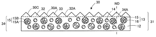
光波長変換シートは、図4および図5に示されるように、レンズ部32を備える光波長変換層31のみからなる光波長変換シート30であってもよい。光波長変換層31がレンズ部32を備えることにより、光波長変換シート30が、光波長変換機能の他、レンズ機能を有するので、レンズシートを1枚省略することが可能であり、更なる薄型化および製造コストの低減を図ることができる。
As shown in FIGS. 4 and 5, the light wavelength conversion sheet may be a light
光波長変換シート30は、シート全体で、40℃、相対湿度90%での水蒸気透過率が0.1g/(m2・24h)以上および/または23℃、相対湿度90%での酸素透過率が0.1cm3/(m2・24h・atm)以上となっている。光波長変換シート30における40℃、相対湿度90%での水蒸気透過率は1g/(m2・24h)以上となっていてもよく、また光波長変換シート30における23℃、相対湿度90%での酸素透過率が1cm3/(m2・24h・atm)以上となっていてもよい。また、光波長変換シート30の光波長変換層31は、量子ドット15の劣化抑制機能を有している。
The light
レンズ部32は光波長変換シート30の一部である。レンズ部32としては、集光性を有するレンズ部が挙げられる。光波長変換シート30の出光面30Aは、レンズ部32のレンズ面32Aとなっているが、光波長変換シートがレンズ部を備える場合、光波長変換シートの入光面および出光面のいずれかがレンズ面となっていればよい。本明細書において、「レンズ面」とは、レンズ部においてレンズ作用(屈折作用)を奏する面のことをいう。
The
レンズ部32は、複数の単位レンズ33を備えている。図3および図4に示されるように単位レンズ33は光波長変換シート30と同様の構成となっている本体部33上に隙間をあけることなく並べられている。図3に示されるように単位レンズ33は、単位レンズ33の配列方向ADと交差する方向に線状、とりわけ本実施の形態においては直線状に、延びている。また本実施の形態において、多数の単位レンズ33は、互いに平行に延びている。また、単位レンズ33の長手方向LDは、光波長変換シート30における単位レンズ33の配列方向ADと直交している。
The
単位レンズは、三角柱状であってもよいし、波状や例えば半球状のような椀状であってもよい。具体的には、単位レンズ部としては、単位プリズム部、単位シリンドリカルレンズ部、単位マイクロレンズ部等が挙げられる。本実施形態では、単位レンズとして、出光側に向けて幅が狭くなる三角柱状の単位プリズム部について説明する。図4に示される光波長変換シート30の本体部34のシート面の法線方向NDおよび単位レンズ33の配列方向ADの両方に平行な断面(光波長変換シートの主切断面とも呼ぶ)の形状は、出光側に突出する三角形形状となっている。とりわけ、正面方向輝度を集中的に向上させるという観点から、主切断面における単位レンズ33の断面形状は二等辺三角形形状であるとともに、等辺の間に位置する頂角が本体部34の出光側面34Aから出光側に突出するように、各単位レンズ33が構成されている。
The unit lens may have a triangular prism shape, a wavy shape, or a bowl shape such as a hemisphere. Specifically, examples of the unit lens unit include a unit prism unit, a unit cylindrical lens unit, and a unit microlens unit. In the present embodiment, a triangular prism unit prism portion whose width becomes narrower toward the light output side will be described as a unit lens. The shape of a cross section (also called a main cutting surface of the light wavelength conversion sheet) parallel to both the normal direction ND of the sheet surface of the
単位レンズ33は、光の利用効率を向上させる観点から、80°以上100°以下の頂角を有することが好ましく、約90°の頂角を有することがより好ましい。ただし、光波長変換シートの巻き取りの際における単位レンズの先端の破損を考慮すると、単位レンズ33の先端は曲面であってもよい。
The
光波長変換シート30の寸法は、一例として、以下のように設定され得る。まず、単位レンズ33の具体例として、単位レンズ33の配列ピッチ(図示された例では、単位レンズ33の幅に相当)を10μm以上200μm以下とすることができる。ただし、昨今においては、単位レンズ33の配列の高精細化が急速に進んでおり、単位レンズ33の配列ピッチを10μm以上50μm以下とすることが好ましい。また、光波長変換シート30のシート面への法線方向NDに沿った本体部34からの単位レンズ33の突出高さを5μm以上100μm以下とすることができる。さらに、単位レンズ33の頂角を60°以上120°以下とすることができる。
The dimension of the light
光波長変換シートは、図6および図7に示されるように、光波長変換層11の他、光学部材41をさらに備える光波長変換シート40であってもよい。図6および図7に示されるように、光波長変換シート40は、光波長変換層11と、光波長変換層11の片面側に配置された光学部材41と、光波長変換層11と光学部材41を貼り合わせるための接着層42とを備えている。光波長変換層11と光学部材41は接着層42を解して接合されているので、光波長変換層11と光学部材41は空気層を介さずに一体化されている。本実施形態においては、光波長変換層11の片側のみに光学部材41が設けられているが、光波長変換層の両側に光学部材が設けられていてもよい。また、本実施形態においては、光波長変換層11と光学部材41が接着層42を介して貼り合わせられているが、光学部材に光波長変換層用組成物を直接塗布、硬化させることによって光波長変換層と光学部材とを直接接合してもよい。
As shown in FIGS. 6 and 7, the light wavelength conversion sheet may be a light
本明細書において、「光学部材」とは、光学的特性(例えば、偏光性、光屈折性、光散乱性、光反射性、光透過性、光吸収性、光回折性、旋光性など)を有する部材を意味し、光学的特性を有するシート(フィルム)状ないし板状の部材であれば、特に限定されない。光学部材としては、レンズシート、導光板および光拡散板等の光学板、反射型偏光分離シート、偏光板等が挙げられる。なお、光学部材が、光波長変換シートの両面側に設けられている場合には、光学部材はそれぞれ別の光学的特性を有する光学部材であってもよい。本実施形態においては、光学部材41が、光透過性基材43と、光透過性基材43の一方の面に設けられ、かつ複数の単位レンズ45を有するレンズ層44とを備えるレンズシートである例について説明する。レンズシートの単位レンズの形状は、三角柱状であってもよく、また波状や、半球状のような椀状であってもよい。そのような単位レンズ形状を有するレンズシートとしては、プリズムシート、レンチキュラーレンズシート、マイクロレンズシート等が挙げられる。
In this specification, the “optical member” means optical properties (for example, polarization, light refraction, light scattering, light reflectivity, light transmission, light absorption, light diffraction, optical rotation, etc.). It is not particularly limited as long as it is a sheet (film) -like or plate-like member having optical characteristics. Examples of the optical member include a lens sheet, an optical plate such as a light guide plate and a light diffusion plate, a reflective polarization separation sheet, and a polarizing plate. In addition, when the optical member is provided on both surface sides of the light wavelength conversion sheet, the optical member may be an optical member having different optical characteristics. In the present embodiment, the
光波長変換シート40は、シート全体で、40℃、相対湿度90%での水蒸気透過率が0.1g/(m2・24h)以上および/または23℃、相対湿度90%での酸素透過率が0.1cm3/(m2・24h・atm)以上となっている。光波長変換シート40における40℃、相対湿度90%での水蒸気透過率は1g/(m2・24h)以上となっていてもよく、また光波長変換シート40における23℃、相対湿度90%での酸素透過率が1cm3/(m2・24h・atm)以上となっていてもよい。
The light
<<光学部材>>
レンズシートとしての光学部材41は、入射した光の進行方向を変化させて出光側から出射させる機能を有する。本実施形態においては、図7に示されるように、入射した光L3の進行方向を変化させて出光側から出射させて、正面方向の輝度を集中的に向上させる機能(集光機能)とともに、入射した光L4を反射させて、光波長変換層11側に戻す機能(再帰反射機能)を有している。光制御シート41は、上記したように、光透過性基材43と、光透過性基材43の一方の面に設けられ、かつ複数の単位レンズ45を有するレンズ層44とを備えている。
<< Optical member >>
The
<光透過性基材>
光透過性基材43としては、光透過性基材21と同様のものであるので、ここでは説明を省略するものとする。
<Light transmissive substrate>
Since the
<レンズ層>
レンズ層44は、複数の単位レンズ45を備えているが、その他、シート状の本体部46を備えている。複数の単位レンズ45は、本体部46の出光側に並べて配置されている。
<Lens layer>
The
本体部46は、単位レンズ45を支持するシート状部材として機能する。図7に示されるように、本体部46の出光側面46A上には、単位レンズ45が隙間をあけることなく並べられている。したがって、光学部材制御シート41の出光面は、レンズ面44Aによって形成されている。その一方で、図7に示すように、本実施の形態において、本体部46は、出光側面46Aに対向する入光側面46Bとして、レンズ層44の入光側面をなす平滑な面を有している。単位レンズ45は、単位レンズ33と同様のものであるので、ここでは説明を省略するものとする。
The
光波長変換シートは、図8に示されるように、光波長変換層11と、光波長変換層11の両面を覆うオーバーコート層51、52とを備える光波長変換シート50であってもよい。本実施形態においては、光波長変換層11の両面にオーバーコート層51、52が形成されているが、オーバーコート層は光波長変換層の少なくとも一方の面に形成されていれば、光波長変換層11の両面に形成されていなくともよい。なお、光波長変換層の一方の面のみにオーバーコート層が設けられている場合、光波長変換層の他方の面には光透過性基材が設けられていてもよい。
As shown in FIG. 8, the light wavelength conversion sheet may be a light
光波長変換シート50は、シート全体で、40℃、相対湿度90%での水蒸気透過率が0.1g/(m2・24h)以上および/または23℃、相対湿度90%での酸素透過率が0.1cm3/(m2・24h・atm)以上となっている。光波長変換シート50における40℃、相対湿度90%での水蒸気透過率は1g/(m2・24h)以上となっていてもよく、また光波長変換シート50における23℃、相対湿度90%での酸素透過率が1cm3/(m2・24h・atm)以上となっていてもよい。
The light
<<オーバーコート層>>
オーバーコート層51、52は、光波長変換層11の表面を覆い、かつ塗工によって形成された樹脂からなる層である。オーバーコート層51、52上に光拡散層等の他の層が形成されていてもよい。
<< Overcoat layer >>
The overcoat layers 51 and 52 are layers made of a resin that covers the surface of the light
オーバーコート層51、52は、光波長変換層11が直接大気に暴露されるのを防ぐために設けられているものである。このようなオーバーコート層51、52を光波長変換層11の少なくとも一方の面に設けることにより、量子ドット15を水分や酸素から保護することができ、また光透過性基材を光波長変換層11の少なくとも一方の面に設けるよりも、光波長変換シートの厚みを薄くできる。
The overcoat layers 51 and 52 are provided to prevent the light
オーバーコート層51、52は、光波長変換層11が直接大気に暴露されるのを防ぐ機能以外に、何らかの機能を有していてもよい。具体的には、オーバーコート層51、52は、例えば、アンチブロッキング性、光拡散性、帯電防止性、および反射防止性等の少なくともいずれかの機能を有する層であってもよい。オーバーコート層51、52が、光波長変換層11が直接大気に暴露されるのを防ぐ機能およびその他何らかの機能を有する層である場合、オーバーコート層51、52には、何らかの機能を有するための材料が添加されていてもよい。
The overcoat layers 51 and 52 may have some function in addition to the function of preventing the light
オーバーコート層51、52の膜厚は、光波長変換層11が直接大気に暴露されるのを防ぐとともに、光波長変換シートを薄型化する観点から、0.1μm以上100μm以下となっていることが好ましい。オーバーコート層の膜厚は、光透過性基材21の厚みと同様の手法によって測定することができる。オーバーコート層51、52の膜厚の下限は1μm以上であることがより好ましく、上限は50μm以下であることがより好ましい。
The film thicknesses of the overcoat layers 51 and 52 are 0.1 μm or more and 100 μm or less from the viewpoint of preventing the light
オーバーコート層51、52は、スクラッチ試験において垂直力10μN以上および/または水平力−5μN以下となる硬度を有することが好ましい。オーバーコート層51、52がこのような硬度を有している場合には、オーバーコート層51、52は緻密な膜となるので、光波長変換層11を大気暴露から防ぐ能力が高い。スクラッチ試験における垂直力および水平力は、ナノインデンテーション装置(製品名「TI950 TriboIndenter」、HYSITRON(ハイジトロン)社製)を用いて、オーバーコート層の断面からオーバーコート層の内部方向に圧子(Cube Corner:Ti037_110410(12))を50nm押し込み、その深さを一定として、30秒間この圧子を移動速度4μm/minで水平方向に移動させた際に測定される垂直力(荷重)および水平力の平均値をそれぞれ求め、さらにこのスクラッチ試験を5回繰り返すことによって求めた垂直力の5つの平均値の平均値(5回平均値)および水平力の5つの平均値の平均値(5回平均値)とする。垂直力は数値が大きいほど、水平力は数値が小さいほどオーバーコート層51、52の硬度が高い。光波長変換層11を大気暴露から防ぐ能力を高める観点から、オーバーコート層51、52のスクラッチ試験における垂直力は15μN以上であることがより好ましく、また水平力は−8μN以下であることがより好ましい。
The overcoat layers 51 and 52 preferably have a hardness that provides a vertical force of 10 μN or more and / or a horizontal force of −5 μN or less in a scratch test. When the overcoat layers 51 and 52 have such hardness, since the overcoat layers 51 and 52 are dense films, the ability to prevent the light
オーバーコート層51、52は、上記硬度を有すれば、特に限定されないが、例えば、(メタ)アクリレート系化合物、エポキシ化合物、イソシアネートおよびポリオールの組み合わせ、金属アルコキシド、ケイ素含有樹脂、水溶性高分子、またはこれらの混合物を含むオーバーコート層用組成物を用いて形成することが可能である。これらの中でも、オーバーコート層51、52は、光波長変換層11が直接大気に暴露されるのを防ぐ観点から、アクリル酸亜鉛、アルコキシシランの加水分解生成物、ポリビニルアルコール、ポリシラザン、またはこれらの混合物を含むオーバーコート層用組成物を用いて形成されることが好ましい。
The overcoat layers 51 and 52 are not particularly limited as long as they have the above hardness. For example, a combination of a (meth) acrylate compound, an epoxy compound, an isocyanate and a polyol, a metal alkoxide, a silicon-containing resin, a water-soluble polymer, Alternatively, it can be formed using a composition for an overcoat layer containing a mixture thereof. Among these, the overcoat layers 51 and 52 are made of zinc acrylate, a hydrolysis product of alkoxysilane, polyvinyl alcohol, polysilazane, or these from the viewpoint of preventing the light
なお、光波長変換シート20、30、40、50においても、60℃、相対湿度90%の環境下に500時間放置する耐久性試験の前後において、光波長変換シート20、30、40の一方の表面の中央部に量子ドットによって波長変換される所定の光量の光を照射して、光波長変換シート20、30、40、50の他方の表面の中央部から出射する光の輝度を測定したとき、耐久性試験前の光波長変換シート20、30、40、50の他方の表面の中央部から出射する光の輝度に対する耐久性試験後の光波長変換シート20、30、40、50の他方の表面の中央部から出射する光の輝度の変化率が±10%以内となっていることが好ましく、±5%以内であることがより好ましい。また、光波長変換シート20、30、40、50においても、60℃、相対湿度90%の環境下に500時間放置する耐久性試験を行ったとき、耐久性試験後の光波長変換シート20、30、40、50における周縁部の劣化幅が5mm以下となることが好ましく、3mm以下となることがより好ましい。
In addition, in the light
<<<光波長変換シートの製造方法>>>
光波長変換シート10は、例えば、以下のようにして作製することができる。図9は本実施形態に係る光波長変換シートの模式的な製造工程図である。まず、図9(A)に示されるように、基材55の一方の面に、硬化性バインダ樹脂前駆体56および硬化性バインダ樹脂前駆体56中に分散した光変換波長粒子13を含む光波長変換層用組成物を塗布し、乾燥させて、光波長変換層用組成物の塗膜57を形成する。基材52としては、光透過性基材であってもよいが、光透過性基材でなくともよい。光波長変換層用組成物には重合開始剤を含ませることが好ましい。
<<< Method for Producing Light Wavelength Conversion Sheet >>>
The light
重合開始剤は、光または熱により分解されて、ラジカルやイオン種を発生させて硬化性樹脂前駆体の重合(架橋)を開始または進行させる成分である。光波長変換層用組成物に用いられる重合開始剤は、光重合開始剤(例えば、光ラジカル重合開始剤、光カチオン重合開始剤、光アニオン重合開始剤)、熱重合開始剤(例えば、熱ラジカル重合開始剤、熱カチオン重合開始剤、熱アニオン重合開始剤)、またはこれらの混合物が挙げられる。 The polymerization initiator is a component that is decomposed by light or heat to generate radicals or ionic species to initiate or advance polymerization (crosslinking) of the curable resin precursor. The polymerization initiator used in the composition for a light wavelength conversion layer is a photopolymerization initiator (for example, a photo radical polymerization initiator, a photo cationic polymerization initiator, a photo anion polymerization initiator), a thermal polymerization initiator (for example, a thermal radical). Polymerization initiator, thermal cationic polymerization initiator, thermal anionic polymerization initiator), or a mixture thereof.
上記光ラジカル重合開始剤としては、例えば、ベンゾフェノン系化合物、アセトフェノン系化合物、アシルフォスフィンオキサイド系化合物、チタノセン系化合物、オキシムエステル系化合物、ベンゾインエーテル系化合物、チオキサントン等が挙げられる。 Examples of the photo radical polymerization initiator include benzophenone compounds, acetophenone compounds, acylphosphine oxide compounds, titanocene compounds, oxime ester compounds, benzoin ether compounds, thioxanthones, and the like.
上記光ラジカル重合開始剤のうち市販されているものとしては、例えば、IRGACURE184、IRGACURE369、IRGACURE379、IRGACURE651、IRGACURE819、IRGACURE907、IRGACURE2959、IRGACURE OXE01、ルシリンTPO(いずれもBASFジャパン社製)、NCI−930(ADEKA社製)、SPEEDCURE EMK(日本シーベルヘグナー社製)、ベンソインメチルエーテル、ベンゾインエチルエーテル、ベンゾインイソプロピルエーテル(いずれも東京化成工業社製)等が挙げられる。 Examples of commercially available photo radical polymerization initiators include IRGACURE 184, IRGACURE 369, IRGACURE 379, IRGACURE 651, IRGACURE 819, IRGACURE 907, IRGACURE 2959, IRGACURE OXE01, and Lucillin TPO (all manufactured by BASF Japan 9) ADEKA), SPEEDCURE EMK (Nihon Sebel Hegner), benzoin methyl ether, benzoin ethyl ether, benzoin isopropyl ether (all manufactured by Tokyo Chemical Industry Co., Ltd.) and the like.
上記光カチオン重合開始剤としては、例えば、芳香族ジアゾニウム塩、芳香族ヨードニウム塩、芳香族スルホニウム塩等が挙げられる。上記光カチオン重合開始剤のうち市販されているものとしては、例えば、アデカオプトマーSP−150、アデカオプトマーSP−170(いずれもADEKA社製)等が挙げられる。 As said photocationic polymerization initiator, aromatic diazonium salt, aromatic iodonium salt, aromatic sulfonium salt etc. are mentioned, for example. Examples of commercially available photocationic polymerization initiators include Adekaoptomer SP-150 and Adekaoptomer SP-170 (both manufactured by ADEKA).
上記熱ラジカル重合開始剤としては、例えば、過酸化物やアゾ化合物等が挙げられる。これらの中でも、高分子アゾ化合物からなる高分子アゾ開始剤が好ましい。高分子アゾ開始剤としては、例えば、アゾ基を介してポリアルキレンオキサイドやポリジメチルシロキサン等のユニットが複数結合した構造を有するものが挙げられる。 Examples of the thermal radical polymerization initiator include peroxides and azo compounds. Among these, a polymer azo initiator composed of a polymer azo compound is preferable. Examples of the polymer azo initiator include those having a structure in which a plurality of units such as polyalkylene oxide and polydimethylsiloxane are bonded via an azo group.
上記アゾ基を介してポリアルキレンオキサイド等のユニットが複数結合した構造を有する高分子アゾ開始剤としては、例えば、4,4'−アゾビス(4−シアノペンタン酸)とポリアルキレングリコールの重縮合物や、4,4'−アゾビス(4−シアノペンタン酸)と末端アミノ基を有するポリジメチルシロキサンの重縮合物等が挙げられる。 Examples of the polymer azo initiator having a structure in which a plurality of units such as polyalkylene oxide are bonded via the azo group include, for example, a polycondensate of 4,4′-azobis (4-cyanopentanoic acid) and polyalkylene glycol. And polycondensate of 4,4′-azobis (4-cyanopentanoic acid) and polydimethylsiloxane having a terminal amino group.
上記過酸化物としては、例えば、ケトンパーオキサイド、パーオキシケタール、ハイドロパーオキサイド、ジアルキルパーオキサイド、パーオキシエステル、ジアシルパーオキサイド、パーオキシジカーボネート等が挙げられる。 Examples of the peroxide include ketone peroxide, peroxyketal, hydroperoxide, dialkyl peroxide, peroxy ester, diacyl peroxide, and peroxydicarbonate.
上記熱ラジカル重合開始剤のうち市販されているものとしては、例えば、パーブチルO、パーヘキシルO、パーブチルPV(いずれも日油社製)、V−30、V−501、V−601、VPE−0201、VPE−0401、VPE−0601(いずれも和光純薬工業社製)等が挙げられる。 Examples of commercially available thermal radical polymerization initiators include perbutyl O, perhexyl O, perbutyl PV (all manufactured by NOF Corporation), V-30, V-501, V-601, and VPE-0201. , VPE-0401, VPE-0601 (both manufactured by Wako Pure Chemical Industries, Ltd.) and the like.
上記熱カチオン重合開始剤としては、例えば、第四級アンモニウム塩、ホスホニウム塩、スルホニウム塩等の各種オニウム塩類等が挙げられる。上記熱カチオン重合開始剤のうち市販されているものとしては、例えば、アデカオプトンCP−66、アデカオプトンCP−77(いずれもADEKA社製)、サンエイドSI−60L、サンエイドSI−80L、サンエイドSI−100L(いずれも三新化学工業社製)、CIシリーズ(日本曹達社製)等が挙げられる。 Examples of the thermal cationic polymerization initiator include various onium salts such as a quaternary ammonium salt, a phosphonium salt, and a sulfonium salt. Examples of commercially available thermal cationic polymerization initiators include Adeka Opton CP-66, Adeka Opton CP-77 (all manufactured by ADEKA), Sun-Aid SI-60L, Sun-Aid SI-80L, and Sun-Aid SI-100L ( All of them are manufactured by Sanshin Chemical Industry Co., Ltd.) and CI series (manufactured by Nippon Soda Co., Ltd.).
そして、図9(B)に示されるように、光波長変換層用組成物の塗膜57に電離放射線を照射して、または熱を加えて、塗膜57を硬化させて、光波長変換層を形成する。
And as FIG. 9 (B) shows, the
最後に、図9(C)に示されるように、光波長変換層11から基材55を剥離する。これにより、光波長変換層11のみからなる光波長変換シート10が得られる。
Finally, as shown in FIG. 9C, the
図3に示される光波長変換シート20は、基材55として光透過性基材を用い、かつ光波長変換層11形成後に基材55を剥離せずにそのまま残存させることにより得ることができる。
The light
図4に示される光波長変換シート30は、例えば、ドラムプリンティングシステム方式(DPS方式)によって形成することが可能である。すなわち、単位レンズ33の形状に対し逆形状の凹部を有し、かつ回転する成形用型に光波長変換層用組成物を塗工充填し、次いでこれに基材55を供給して型面の光波長変換層用組成物の上から成形用型に押圧する。そして、押圧した状態で、基材51を介して光波長変換層用組成物に紫外線等の電離放射線を照射し、または光波長変換層用組成物に熱を加えて、光波長変換層用組成物を硬化させる。そして、硬化させた光波長変換層用組成物を基材55と共に回転する成形用型から剥離する。これにより、基材55上にレンズ部32有する光波長変換層31が形成される。最後に、光波長変換層31から基材51を剥離する。これにより、レンズ部32を有する光波長変換層31のみからなる光波長変換シート30が得られる。
The light
図6に示される光波長変換シート40は、光波長変換層11形成後に、光波長変換層11における基材55側の面とは反対側の面に、接着層42を介して光学部材41を貼り合わせて、その後光波長変換層11から基材55を剥離することによって得ることができる。なお、基材51が光透過性基材である場合には、基材55を剥離せずにそのまま残存させておいてもよい。また、接着層42を用いずに、光学部材41の光透過性基材43におけるレンズ層44側の面とは反対側の面に光波長変換層用組成物を直接塗布し、光波長変換層用組成物に電離放射線を照射し、または光波長変換層用組成物に熱を加えて、光波長変換層用組成物を硬化させてもよい。この場合、光学部材が基材となる。さらに、基材55の上に塗布した光波長変換層用組成物の塗膜53の塗布面に光学部材41を配置して、その後、塗膜57を硬化させてもよく、また塗膜57を硬化させた後に基材55を剥離してもよい。また、光波長変換層の両面に光学部材を貼り合わせる場合には、光波長変換層における基材側の面とは反対側の面(第1の面)に、接着層を介して光学部材を貼り合わせる前または貼り合わせた後に、光波長変換層から基材を剥離して、基材の剥離後に光波長変換層の第1の面とは反対側の第2の面に接着層を介して上記光学部材とは異なる光学部材を貼り合わせることによって、光波長変換層の両面に光学部材を貼り合わせてもよい。
The optical
図8に示される光波長変換シート50は、光波長変換シート10の少なくとも一方の面にオーバーコート層用組成物を塗布して、オーバーコート層用組成物の塗膜を形成し、この塗膜を硬化させることによって形成することが可能である。
The light
また、光波長変換シート50は、次のような方法によっても形成することが可能である。まず、2枚の基材の一方の面にオーバーコート層用組成物を塗布して、オーバーコート層用組成物の塗膜を形成する。塗膜を形成した後、それぞれのオーバーコート層用組成物の塗膜に電離放射線を照射して、または熱を加えて、オーバーコート層を形成する。オーバーコート層を形成した後、一方の基材に形成されたオーバーコート層上に光波長変換層用組成物を塗布して、光波長変換層用組成物の塗膜を形成する。次いで、光波長変換層用組成物の塗膜に他方の基材に形成されたオーバーコート層が接するように光波長変換層用組成物の塗膜上に他方の基材を配置する。次いで、この状態で、光波長変換層用組成物の塗膜に電離放射線を照射して、または熱を加えて、光波長変換層を形成するとともに、光波長変換層と、オーバーコート層とを一体化させる。最後に両方の基材を剥離すれば、光波長変換シート50が得られる。
The light
本実施形態によれば、光波長変換シート10、20、30、40、50における40℃、相対湿度90%での水蒸気透過率が0.1g/(m2・24h)以上および/または光波長変換シート10、20、30、40、50における23℃、相対湿度90%での酸素透過率が0.1cm3/(m2・24h・atm)以上となっているので、光透過性基材およびバリア層からなるバリアフィルムを備えていない。したがって、バリアフィルムに起因するピンホールやクラックが発生することがなく、これにより、点状の輝度欠点を抑制することができる。また、光波長変換シート10、20、30、40、50においては、光波長変換層11、31が量子ドット15の劣化抑制機能を有しているので、バリアフィルムを備えていなくとも、量子ドット15の劣化を抑制できる。さらに、光波長変換シート10、20、30、40、50においては、バリアフィルムを備えていないので、薄型化および製造コストの低減を図ることができる。
According to this embodiment, the water vapor transmission rate at 40 ° C. and the relative humidity of 90% in the light
通常、光波長変換シートは、光波長変換層の両面にバリアフィルムを設けた状態で所望の大きさに切断するので、切断された光波長変換シートの側面にはバリアフィルムが存在せず、露出している。このため、光波長変換シートの周縁部に存在する量子ドットが光波長変換シートの中央部に存在する量子ドットに比べて劣化しやすい。これに対し、本実施形態によれば、量子ドット15をバリア粒子16で包んだ光波長変換粒子13を用いているので、量子ドット15を水分や酸素から保護することができる。これにより、光波長変換シート10、20、30、40、50における40℃、相対湿度90%での水蒸気透過率が0.1g/(m2・24h)以上および/または23℃、相対湿度90%での酸素透過率が0.1cm3/(m2・24h・atm)以上であったとしても、光波長変換シート10、20、30、40、50の周縁部10C、20C、30C、40C、50C(図1、図3、図5、図7、図8参照)に存在する量子ドット15の劣化を抑制できる。また、本実施形態によれば、量子ドット15をバリア粒子16で包んでいるので、光波長変換層11、31に量子ドット15の劣化抑制機能を付与することができる。
Usually, the light wavelength conversion sheet is cut into a desired size with the barrier films provided on both sides of the light wavelength conversion layer, so that the barrier film does not exist on the side surface of the cut light wavelength conversion sheet and is exposed. doing. For this reason, the quantum dot which exists in the peripheral part of a light wavelength conversion sheet tends to deteriorate compared with the quantum dot which exists in the center part of a light wavelength conversion sheet. On the other hand, according to the present embodiment, since the light
また、本実施形態によれば、量子ドット15をバリア粒子16で包んだ光波長変換粒子13を用いて、量子ドット15の劣化を抑制しているので、光波長変換シート10、20、30、40、50における40℃、相対湿度90%での水蒸気透過率が0.1g/(m2・24h)以上および/または23℃、相対湿度90%での酸素透過率が0.1cm3/(m2・24h・atm)以上であったとしても、別途バリアフィルムを設ける必要がないので、光波長変換シート10、30のように単層でも使用することができる。
Moreover, according to this embodiment, since the deterioration of the
本実施形態によれば、光波長変換シート10、20、30、40、50における40℃、相対湿度90%での水蒸気透過率が0.1g/(m2・24h)以上および/または23℃、相対湿度90%での酸素透過率が0.1cm3/(m2・24h・atm)以上であったとしても、光波長変換シート10、20、30、40、50を60℃、相対湿度90%の環境下に500時間放置する耐久性試験の前後において、耐久性試験前の光波長変換シート10、20、30、40、50の表面の中央部から出射する光の輝度に対する耐久性試験後の光波長変換シート10、20、30、40、50の表面の中央部から出射する光の輝度の変化率が±10%以内となっている場合には、光波長変換シート10、20、30、40、50の中心部の劣化を抑制できる。また、この場合には、60℃、相対湿度90%の環境下に500時間放置する耐久性試験後の光波長変換シート10、20、30、40、50における周縁部の劣化幅を5mm以下とすることができる。これにより、バリアフィルムを設けなくとも、光波長変換シート10、20、30、40、50の中心部および周縁部の劣化を抑制することができる。
According to the present embodiment, the water vapor permeability at 40 ° C. and relative humidity of 90% in the light
上述したように従来の光波長変換シートにおいては側面が露出しているので、光波長変換シートの周縁部の量子ドットが劣化してしまう。そして、光波長変換シートの周縁部の量子ドットが劣化してしまうと、波長変換効率が低下してしまう。このことが原因の一つとなって、光源からの光を光波長変換シートに入射させた場合に、光波長変換シートの周縁部から出射される光の色味が中央部から出射される光の色味に比べて際立ってしまうことがある。これに対し、本実施形態においては、量子ドット15をバリア粒子16で包んだ光波長変換粒子13を用いることにより、光波長変換シート10、20、30、40、50の周縁部に存在する量子ドット15の劣化を抑制できるので、光波長変換シート10、20、30、40、50の周縁部から出射される光の色味が中央部の色味に比べて際立つことを抑制することができる。
As described above, since the side surface is exposed in the conventional light wavelength conversion sheet, the quantum dots at the peripheral edge of the light wavelength conversion sheet are deteriorated. And if the quantum dot of the peripheral part of a light wavelength conversion sheet deteriorates, wavelength conversion efficiency will fall. This is one of the causes, and when the light from the light source is incident on the light wavelength conversion sheet, the color of the light emitted from the peripheral edge of the light wavelength conversion sheet is the light emitted from the center. May stand out compared to color. On the other hand, in the present embodiment, quantum wavelengths existing in the peripheral portions of the light
上述したように、バリアフィルムを備えていると、バリアフィルムにピンホールやクラックが発生し、そこから水分や酸素が光波長変換シートに浸入し、量子ドットが劣化してしまうおそれがある。バリアフィルムのクラックは、光波長変換シートを折り曲げた場合に特に発生しやすい。これに対し、本実施形態においては、バリアフィルムを設けていないので、フォールダブルにも対応することができる。 As described above, when the barrier film is provided, pinholes and cracks are generated in the barrier film, and moisture and oxygen enter the light wavelength conversion sheet from there, and the quantum dots may be deteriorated. Cracks in the barrier film are particularly likely to occur when the light wavelength conversion sheet is folded. On the other hand, in this embodiment, since the barrier film is not provided, it is possible to deal with foldable.
本実施形態によれば、別途バリアフィルムを設ける必要がないので、厚みに厳しい要件があるモバイル製品(いわゆるスマートフォンと称される機器を含む携帯用コンピュータ端末機器)にも対応することができる。 According to this embodiment, since it is not necessary to provide a separate barrier film, it can also be applied to mobile products (portable computer terminal devices including devices called so-called smartphones) that have strict requirements on thickness.
本実施形態によれば、光波長変換シート10、20、30、40、50が光散乱粒子14を含んでいるので、緑色の発光が赤色の発光よりも優先的に増強させることができる。この理由は明確ではないが、光散乱粒子は、青色光を緑色光に変換する第1の量子ドットから、青色光を赤色光に変換する第2の量子ドットへのエネルギー移動を阻害するような役割を果たしていると考えられ、本来上記エネルギー移動により失活していた緑色の発光が失活することなく発光過程に至り、結果として緑色の発光が増加するためであると考えられる。
According to the present embodiment, since the light
従来、光波長変換層の両面にバリアフィルムを備える光波長変換シートの厚みは300μm程度であるので、光波長変換シートとレンズシート等の光学部材とを貼り合わせることは困難であり、別々に配置されていた。このため、バックライト装置の組み立て作業が煩雑になり、また光波長変換シートと光制御シートとの間に異物が入り込むことがあり、さらに光波長変換シートと光学部材との間に空気界面が存在するので光利用効率が低下するおそれがあった。これに対し、本実施形態に係る光波長変換シートはバリアフィルムを必要としないので、厚みを極めて薄くできる。このため、光波長変換シート40のように光波長変換層と光学部材とを貼り合わせることが可能となる。これにより、光波長変換シートと光学部材とを別個独立に配置する場合に比べて、バックライト装置の組み立て作業を容易になり、また光波長変換層と光制御シートとの間に異物が入り込むことを抑制でき、さらに省スペース化および部材の簡素化を図ることができる。
Conventionally, since the thickness of the light wavelength conversion sheet provided with the barrier films on both surfaces of the light wavelength conversion layer is about 300 μm, it is difficult to bond the light wavelength conversion sheet and an optical member such as a lens sheet, which are arranged separately. It had been. For this reason, the assembling work of the backlight device becomes complicated, foreign matter may enter between the light wavelength conversion sheet and the light control sheet, and an air interface exists between the light wavelength conversion sheet and the optical member. As a result, the light utilization efficiency may be reduced. On the other hand, since the light wavelength conversion sheet according to the present embodiment does not require a barrier film, the thickness can be extremely reduced. For this reason, the light wavelength conversion layer and the optical member can be bonded together like the light
光波長変換シート10、20、30、40、50は、バックライト装置および画像表示装置に組み込んで使用することができる。以下、光波長変換シート10をバックライト装置および画像表示装置に組み込んだ例について説明する。図10は本実施形態に係るバックライト装置を含む画像表示装置の概略構成図であり、図11は図10に示されるレンズシートの斜視図であり、図12は本実施形態に係る他のバックライト装置の概略構成図である。
The light
<<<画像表示装置>>>
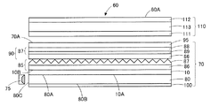
図10に示される画像表示装置60は、バックライト装置70と、バックライト装置70の出光側に配置された表示パネル110とを備えている。画像表示装置60は、画像を表示する表示面60Aを有している。図10に示される画像表示装置60においては、表示パネル110の表面が表示面60Aとなっている。
<<< Image display device >>>
An
バックライト装置60は、表示パネル110を背面側から面状に照らすものである。表示パネル110は、バックライト装置60からの光の透過または遮断を画素毎に制御するシャッターとして機能し、表示面60Aに像を表示するように構成されている。
The
<<表示パネル>>
図10に示される表示パネル110は、液晶表示パネルであり、入光側に配置された偏光板111と、出光側に配置された偏光板112と、偏光板111と偏光板112との間に配置された液晶セル113とを備えている。偏光板111、112は、入射した光を直交する二つの直線偏光成分(S偏光およびP偏光)に分解し、一方の方向(透過軸と平行な方向)に振動する直線偏光成分(例えば、P偏光)を透過させ、前記一方の方向に直交する他方の方向(吸収軸と平行な方向)に振動する直線偏光成分(例えば、S偏光)を吸収する機能を有している。
<< Display panel >>
A
液晶セル113には、一つの画素を形成する領域毎に、電圧の印加がなされ得るように構成されている。そして、電圧印加の有無によって液晶セル113中の液晶分子の配向方向が変化するようになる。一例として、入光側に配置された偏光板111を透過した特定方向の直線偏光成分は、電圧印加がなされた液晶セル113を通過する際にその偏光方向を90°回転させ、その一方で、電圧印加がなされていない液晶セル113を通過する際にその偏光方向を維持する。この場合、液晶セル113への電圧印加の有無によって、偏光板111を透過した特定方向に振動する直線偏光成分を偏光板112に対して透過させ、または偏光板112で吸収して遮断することができる。このようにして、表示パネル110では、バックライト装置70からの光の透過または遮断を画素毎に制御し得るように構成されている。なお、液晶表示パネルの詳細については、種々の公知文献(例えば、「フラットパネルディスプレイ大辞典(内田龍男、内池平樹監修)」2001年工業調査会発行)に記載されており、ここではこれ以上の詳細な説明を省略する。
The
<<バックライト装置>>
図10に示されるバックライト装置70は、エッジライト型のバックライト装置として構成され、光源75と、光源75の側方に配置された導光板としての光学板80と、光学板80の出光側に配置された光波長変換シート10と、光波長変換シート10の出光側に配置されたレンズシート85と、レンズシート85の出光側に配置されたレンズシート90と、レンズシート90の出光側に配置された反射型偏光分離シート95と、光学板80の出光側とは反対側に配置された反射シート100とを備えている。バックライト装置70は、光学板80、レンズシート85、90、反射型偏光分離シート95、反射シート100を備えているが、これらのシート等は備えられていなくともよい。本明細書において、「出光側」とは、各部材においてバックライト装置から出射する方向に向かう光が出射される側を意味する。
<< Backlight device >>
A
バックライト装置70は、面状に光を発光する発光面70Aを有している。図10に示されるバックライト装置70においては、反射型偏光分離シート95の出光面がバックライト装置70の発光面70Aとなっている。
The
光波長変換シート10における光学板80側の面が入光面10Aとなっており、光波長変換シート10におけるレンズシート85側の面が出光面10Bとなっている。
The surface on the
<光源>
光源75は、例えば、線状の冷陰極管等の蛍光灯や、点状の発光ダイオード(LED)や白熱電球等の種々の態様で構成され得る。本実施の形態において、光源75は、光学板60の後述する入光面80C側に、線状に並べて配置された多数の点状発光体、具体的には、多数の発光ダイオード(LED)によって、構成されている。
<Light source>
The
バックライト装置70においては光波長変換シート10が配置されていることに伴い、光源75は、単一の波長域の光を放出する発光体のみを用いることができる。例えば、光源は、色純度の高い青色光を発する青色発光ダイオードのみを用いることができる。
As the light
<光学板>
導光板としての光学板80は、平面視形状が四角形形状に形成されている。光学板80は、表示パネル110側の一方の主面によって構成された出光面80Aと、出光面80Aに対向するもう一方の主面からなる裏面80Bと、出光面80Aおよび裏面80Bの間を延びる側面と、を有している。側面のうちの光源75側の側面が、光源75からの光を受ける入光面80Cとなっている。入光面80Cから光学板80内に入射した光は、入光面80Cと、入光面80Cと対向する反対面とを結ぶ方向(導光方向)に光学板内を導光され、出光面80Aから出射される。
<Optical plate>
The
光波長変換シート10がアンチブロッキング剤等により入光面10Aが凹凸面となっている場合には、出光面80Aは、入光面10Aの一部(例えば、凸部)と光学的に密着し、また入光面10Aの他の部分(例えば、凹部)と離間していることが好ましい。この場合、出光面80Aと入光面10Aの他の部分との隙間は空気層となっている。この空気層を設けることにより、出光面80Aと入光面10Aが光学的に密着するように出光面60Aに対して光波長変換シート10を固定した場合であっても、出光面80Aに光波長変換シート10が貼り付くことを抑制できるので、光波長変換シート10と光学板80との間の界面にウエットアウトが形成されることを抑制できる。本明細書において、「光学的に密着」とは、光学板の出光面と光波長変換シートの入光面の一部がその間に空気層を形成することなく密着している状態をいう。また、光学板の出光面に光波長変換シートが貼り付いていない状態とは、光波長変換シートと光学板の固定を解除した場合に、光学板の出光面から該出光面の平面方向に光波長変換シートを動かせることを意味する。
In the case where the light
光学板80を構成する材料としては、画像表示装置に組み込まれる光学シート用の材料として広く使用され、優れた機械的特性、光学特性、安定性および加工性等を有するとともに安価に入手可能な材料、例えば、アクリル樹脂、ポリスチレン、ポリカーボネート、ポリエチレンテレフタレート、ポリアクリロニトリル等の一以上を主成分とする透明樹脂や、エポキシアクリレートやウレタンアクリレート系の反応性樹脂(電離放射線硬化型樹脂等)が好適に使用され得る。なお、必要に応じて、光学板60中に光を拡散させる機能を有する光拡散材を添加することもできる。光拡散材としては、例えば、平均粒子径が0.5μm以上100μm以下のシリカ(二酸化珪素)、アルミナ(酸化アルミニウム)、アクリル樹脂、ポリカーボネート樹脂、シリコーン樹脂等の透明物質からなる粒子を用いることができる。
As a material constituting the
<レンズシート>
図11に示されるように、レンズシート85、90は、光学部材41と同様の構成となっている。すなわち、レンズシート85、90は、光透過性基材86と、光透過性基材86の一方の面に設けられ、かつ複数の単位レンズ88を有するレンズ層87とを備えており、レンズ層87は単位レンズ88の他、シート状の本体部89を備えている。光透過性基材86、レンズ層87、単位レンズ88、本体部89は、光学部材41における光透過性基材43、レンズ層44、単位レンズ45、本体部46と同様であるので、ここでは説明を省略するものとする。
<Lens sheet>
As shown in FIG. 11, the
図10から理解され得るように、レンズシート85の単位レンズ88の配列方向とレンズシート90の単位レンズ88の配列方向とは交差、さらに限定的には直交している。
As can be understood from FIG. 10, the arrangement direction of the
<反射型偏光分離シート>
反射型偏光分離シート95は、レンズシート85から出射される光のうち、第1の直線偏光成分(例えば、P偏光)のみを透過し、かつ第1の直線偏光成分と直交する第2の直線偏光成分(例えば、S偏光)を吸収せずに反射する機能を有する。反射型偏光分離シート95で反射された第2の直線偏光成分は再度反射され、偏光が解消された状態(第1の直線偏光成分と第2の直線偏光成分とを両方含んだ状態)で、再度、反射型偏光分離シート95に入射する。よって、反射型偏光分離シート95は再度入射する光のうち第1の直線偏光成分を透過し、第1の直線偏光成分と直交する第2の直線偏光成分は再度反射される。以下、同上の過程を繰り返す事により、レンズシート75から出光した光の70〜80%程度が第1の直線偏光成分となった光源光として出光される。したがって、反射型偏光分離シート95の第1の直線偏光成分(透過軸成分)の偏光方向と表示パネル110の偏光板111の透過軸方向とを一致させることにより、バックライト装置50からの出射光は全て表示パネル110で画像形成に利用可能となる。したがって、光源75から投入される光エネルギーが同じであっても、反射型偏光分離シート95を未配置の場合に比べて、より高輝度の画像形成が可能となり、又光源75のエネルギー利用効率も向上する。とりわけ、反射型偏光分離シート95で反射された光は、光波長変換シート10で波長変換が行われ得る。したがって、反射型偏光分離シート95を配置することによって、光波長変換シート10の波長変換効率がさらに上昇させることができる。したがって、更なる光の利用効率の改善を期待することができる。
<Reflection-type polarized light separation sheet>
The reflection-type
反射型偏光分離シート95としては、3M社から入手可能な「DBEF」(登録商標)を用いることができる。また、「DBEF」以外にも、Shinwha Intertek社から入手可能な高輝度偏光シート「WRPS」やワイヤーグリッド偏光子等を、反射型偏光分離シート95として用いることができる。
As the reflective
<反射シート>
反射シート100は、光学板80の裏面80Bから漏れ出した光を反射して、再び光学板80内に入射させる機能を有する。反射シート100は、白色の散乱反射シート、金属等の高い反射率を有する材料からなるシート、高い反射率を有する材料からなる薄膜(例えば金属薄膜)を表面層として含んだシート等から、構成され得る。反射シート85での反射は、正反射(鏡面反射)でもよく、拡散反射でもよい。反射シート85での反射が拡散反射の場合には、当該拡散反射は、等方性拡散反射であってもよいし、異方性拡散反射であってもよい。
<Reflection sheet>
The
<<他のバックライト装置>>
光波長変換シート10を組み込むバックライト装置は、図12に示されるような直下型のバックライト装置であってもよい。図12に示されるバックライト装置120は、光源75と、光源75の光を受け、かつ光拡散板として機能する光学板121と、光学板121の出光側に配置された光波長変換シート10、光波長変換シート10の出光側に配置されたレンズシート85と、レンズシート85の出光側に配置された反射型偏光分離シート95とを備えている。本実施形態においては、光源75は、光学板121の側方ではなく、光学板121の直下に配置されている。図12において、図10と同じ符号が付されている部材は、図10で示した部材と同じものであるので、説明を省略するものとする。なお、バックライト装置120においては、反射シート100は備えられていない。
<< Other backlight devices >>
The backlight device incorporating the light
<光学板>
光拡散板としての光学板121は、平面視形状が四角形形状に形成されている。光学板121は、光源75側の一方の主面によって構成された入光面121Aと、光波長変換シート10側の他方の主面によって構成された出光面121Bとを有している。入光面121Aから光学板121内に入射した光は、光学板121内で散乱され、出光面101Bから出射される。
<Optical plate>
The
光学板121としては、光源75からの光を散乱させることができれば、特に限定されないが、例えば、透明材料中に光散乱性粒子を分散させた板が挙げられる。透明材料としては、特に限定されないが、例えば透明樹脂、無機ガラス等が挙げられる。前記透明樹脂としては、成形が容易である点で、透明熱可塑性樹脂が好適に用いられる。この透明熱可塑性樹脂としては、特に限定されるものではないが、例えば、ポリスチレン樹脂、スチレン−メタクリル酸メチル共重合体樹脂、スチレン−メタクリル酸共重合体樹脂、スチレン−無水マレイン酸共重合体樹脂、メタクリル樹脂、アクリル樹脂、ポリカーボネート樹脂、ABS樹脂(アクリロニトリル−ブタジエン−スチレン共重合体樹脂)、AS樹脂(アクリロニトリル−スチレン共重合体樹脂)、ポリオレフィン樹脂(ポリエチレン樹脂、ポリプロピレン樹脂等)などが挙げられる。これらのうちの1種を用いても良いし、或いはこれらの2種以上を混合して用いても良い。
The
<光散乱性粒子>
光散乱性粒子の平均粒子径としては、例えば、0.5μm以上30μm以下であることが好ましく、1μm以上20μm以下であることがより好ましい。0.5μm未満であると、光波長変換シートの光波長変換効率が不充分となることがあり、充分な光散乱性を出すためには光散乱性粒子の添加量を多くする必要がある。一方、30μmを超えると、光散乱性が悪くなり、また光波長変換層の膜厚に近くなるため製膜が安定しにくくなる。なお、光散乱性粒子の平均粒子径は、上述した量子ドットと同様の方法で測定することができる。
<Light scattering particles>
The average particle diameter of the light scattering particles is, for example, preferably from 0.5 μm to 30 μm, and more preferably from 1 μm to 20 μm. If it is less than 0.5 μm, the light wavelength conversion efficiency of the light wavelength conversion sheet may be insufficient, and it is necessary to increase the amount of light scattering particles added in order to obtain sufficient light scattering properties. On the other hand, when it exceeds 30 μm, the light scattering property is deteriorated, and the film formation becomes difficult to stabilize because it becomes close to the film thickness of the light wavelength conversion layer. In addition, the average particle diameter of light-scattering particle | grains can be measured by the method similar to the quantum dot mentioned above.
光散乱性粒子の平均粒子径は、上述した量子ドットの平均粒子径の10倍以上2万倍以下であることが好ましく、10〜5000倍であることがより好ましい。10倍未満であると、光散乱板に充分な光散乱性が得られないことがあり、2万倍を超えると、光散乱板の光散乱性能は優れたものとなるが、光散乱板の光の透過率が大幅にダウンしやすくなる。 The average particle size of the light-scattering particles is preferably 10 to 20,000 times, more preferably 10 to 5000 times the average particle size of the quantum dots described above. If it is less than 10 times, sufficient light scattering properties may not be obtained for the light scattering plate. If it exceeds 20,000 times, the light scattering performance of the light scattering plate will be excellent. The light transmittance is greatly reduced.
光散乱性粒子は、有機材料からなる粒子または無機材料からなる粒子であってもよい。光散乱性粒子を構成する有機材料としては特に限定されず、例えば、ポリエステル、ポリスチレン、メラミン樹脂、(メタ)アクリル樹脂、アクリル−スチレン共重合体樹脂、シリコーン樹脂、ベンゾグアナミン樹脂、ベンゾグアナミン・ホルムアルデヒド縮合樹脂、ポリカーボネート、ポリエチレン、ポリオレフィン等が挙げられる。なかでも、架橋アクリル樹脂が好適に用いられる。また、上記光散乱性粒子を構成する無機材料としては特に限定されず、例えば、シリカ、アルミナ、チタニア、酸化スズ、アンチモンドープ酸化スズ(ATO)、酸化亜鉛微粒子等の無機酸化物等が挙げられる。なかでも、シリカ及び/又はアルミナが好適に用いられる。 The light scattering particles may be particles made of an organic material or particles made of an inorganic material. The organic material constituting the light scattering particles is not particularly limited. For example, polyester, polystyrene, melamine resin, (meth) acrylic resin, acrylic-styrene copolymer resin, silicone resin, benzoguanamine resin, benzoguanamine / formaldehyde condensation resin , Polycarbonate, polyethylene, polyolefin and the like. Of these, a crosslinked acrylic resin is preferably used. Moreover, it does not specifically limit as an inorganic material which comprises the said light-scattering particle | grains, For example, inorganic oxides, such as a silica, an alumina, a titania, a tin oxide, an antimony dope tin oxide (ATO), a zinc oxide fine particle, etc. are mentioned. . Of these, silica and / or alumina is preferably used.
本実施形態においては、光波長変換シート10をバックライト装置70、120に組み込んだ例について説明しているが、光波長変換シート10に代えて、光波長変換シート20、30、40をバックライト装置70、120に組み込んでもよい。光波長変換シート30、40をバックライト装置70、120に組み込む場合には、レンズ部32や光学部材41がレンズシート85の代わりとなるので、レンズシート85を省略することができる。光波長変換シート30、40は、レンズ部32や光学部材41側がレンズシート90側となるように配置される。
In the present embodiment, an example in which the light
[第2の実施形態]
以下、本発明の第2の実施形態に係る光波長変換シート、バックライト装置および画像表示装置について、図面を参照しながら説明する。図13は本実施形態に係る光波長変換シートの概略構成図であり、図14および図15は本実施形態に係る光波長変換シートの模式的な製造工程図である。
[Second Embodiment]
Hereinafter, an optical wavelength conversion sheet, a backlight device, and an image display device according to a second embodiment of the present invention will be described with reference to the drawings. FIG. 13 is a schematic configuration diagram of the light wavelength conversion sheet according to the present embodiment, and FIGS. 14 and 15 are schematic manufacturing process diagrams of the light wavelength conversion sheet according to the present embodiment.
<<<光波長変換シート>>>
図13に示される光波長変換シート130は、光波長変換層131と、光波長変換層131の両面に設けられた光透過性基材132、133と、光透過性基材132、133における光波長変換層131側の面とは反対側に設けられた光拡散層134、135とを備えている。光波長変換シート130においては、光拡散層134、135の表面が光波長変換シート130の表面130A、130Bを構成している。光波長変換シート130は、光透過性基材132、133を備えているが、バリア層を備えていないので、光透過性基材およびバリア層からなるバリアフィルムを備えていない。なお、光波長変換シート130は、光拡散層134/光透過性基材132/光波長変換層131/光透過性基材133/光拡散層135の構造となっているが、光波長変換層を有していれば、光波長変換シートの構造は特に限定されない。
<<< Light wavelength conversion sheet >>>
The light
光波長変換シート130は、シート全体で、40℃、相対湿度90%での水蒸気透過率が0.1g/(m2・24h)以上および/または23℃、相対湿度90%での酸素透過率が0.1cm3/(m2・24h・atm)以上となっている。水蒸気透過率および酸素透過率は、第1の実施形態と同様の手法によって測定される。
The light
光波長変換シート130における40℃、相対湿度90%での水蒸気透過率は1g/(m2・24h)以上となっていてもよく、また光波長変換シート130における23℃、相対湿度90%での酸素透過率が1cm3/(m2・24h・atm)以上となっていてもよい。
The water vapor transmission rate at 40 ° C. and
光波長変換シート130を60℃、相対湿度90%の環境下に500時間放置する耐久性試験の前後において、光波長変換シート130の一方の表面130Aの全面に量子ドット137によって波長変換される所定の光量の光を照射して、光波長変換シート130の表面130Aとは反対側の面である他方の表面130Bの中央部から出射する光の輝度を測定したとき、耐久性試験前の光波長変換シート130の表面130Bの中央部から出射する光の輝度に対する耐久性試験後の光波長変換シート130の表面130Bの中央部から出射する光の輝度の変化率が±10%以内となっていることが好ましく、±5%以内であることが好ましい。
Before and after the durability test in which the light
光波長変換シート130において、60℃、相対湿度90%の環境下に500時間放置する耐久性試験を行ったとき、耐久性試験後の光波長変換シート130における周縁部の劣化幅が5mm以下となることが好ましく、3mm以下となることがより好ましい。
In the light
<<<光波長変換層>>>
光波長変換層131は、例えば、バインダ樹脂136と、バインダ樹脂136に分散された量子ドット137とを含んでいる。光波長変換層131は、光散乱性粒子138をさらに含んでいることが好ましい。また、光波長変換シート131は、後述するように蛍光X線分析により測定される光波長変換層中の特定の元素の含有量を0.5質量%以上にしているので、量子ドット137の劣化抑制機能を有している。
<<< Light wavelength conversion layer >>>
The light
光波長変換層131においては、蛍光X線分析(XRF)により測定される光波長変換層131中の硫黄、リン、および窒素からなる群から選択される1種以上の元素(以下、この元素を「特定の元素」と称する。)の含有量は、0.5質量%以上となっている。特定の元素の含有量が0.5質量%未満であると、量子ドットの劣化を抑制できないおそれがある。特定の元素が2種または3種の元素から構成されている場合には、本明細書における特定の元素の含有量とは、2種または3種の元素の合計の含有量を意味するものとする。特定の元素の含有量の測定は、蛍光X線分析装置(製品名「EDX−800HS」、島津製作所製)を用いることにより行うことができる。蛍光X線分析(XRF)により測定される光波長変換層11中の特定の元素の含有量の下限は、0.5質量%以上であることが好ましく、特定の元素の含有量の上限は20質量%以下であることが好ましく、10質量%以下であることがより好ましい。特定の元素の含有量が20質量%を越えると、光波長変換層の形成時に充分な硬化が行われないおそれがある。
In the light
特定の元素は主にバインダ樹脂136に含まれているが、量子ドット137にも含まれている場合があり、この場合には、光波長変換層131の量子ドット非含有領域において電子顕微鏡付属のエネルギー分散型X線分光分析装置(EDX)による元素分析を行うことによって、バインダ樹脂136の特定の元素の有無を把握することができる。
The specific element is mainly contained in the
光波長変換層131の膜厚は、10μm以上200μm以下となっていることが好ましい。この光波長変換層131の膜厚がこの範囲であれば、バックライト装置の軽量化および薄膜化に適している。光波長変換層131の膜厚は、光波長変換シートの断面を、走査型電子顕微鏡(SEM)を用いて、光波長変換層の断面を撮影し、その断面の画像において光波長変換層の厚みを20箇所測定し、その20箇所の厚みの平均値とする。光波長変換層131の膜厚の上限は170μm未満であることがより好ましい。
The film thickness of the light
<<バインダ樹脂>>
バインダ樹脂136は、硬化性バインダ樹脂前駆体の硬化物(重合物、架橋物)を含む。硬化性バインダ樹脂前駆体は、硫黄化合物、リン化合物、および窒素化合物からなる群から選択される1種以上の化合物(以下、この化合物を「特定の化合物」と称する。)と、重合性化合物とを含むことが好ましい。
<< Binder resin >>
The
<硫黄化合物>
硫黄化合物は、硫黄を含む化合物である。硫黄化合物としては、特に限定されないが、チオール化合物、チオエーテル化合物、ジスルフィド化合物、チオフェン化合物等が挙げられる。硫黄化合物として、チオール化合物を用いた場合には、バインダ樹脂136中においては、チオール化合物と重合性化合物は、チオール−エン反応により共重合体を形成していることが好ましい。チオールと重合性化合物が共重合することにより、チオール化合物をバインダ樹脂中に固定することができる。なお、本実施形態では、チオール化合物と重合性化合物は別々の化合物であるが、1分子中にチオール基とラジカル重合性官能基を有するチオール化合物を用いてもよい。チオール化合物を用いる場合には、塗工時のポットライフや臭気抑制の観点から、特に2級チオール化合物または3級チオール化合物を用いるのが好ましい。
<Sulfur compounds>
A sulfur compound is a compound containing sulfur. Although it does not specifically limit as a sulfur compound, A thiol compound, a thioether compound, a disulfide compound, a thiophene compound etc. are mentioned. When a thiol compound is used as the sulfur compound, in the
2級チオール化合物とは、チオール基が結合している炭素に2つの炭化水素基が結合している化合物をいう。3級チオール化合物とは、チオール基が結合している炭素に3つの炭化水素基が結合している化合物をいう。2級チオール化合物および3級チオール化合物においては、1分子中にチオール基が1以上であればよいが、量子ドットの耐久性向上の観点から、2以上であることが好ましい。 The secondary thiol compound refers to a compound in which two hydrocarbon groups are bonded to carbon to which a thiol group is bonded. The tertiary thiol compound refers to a compound in which three hydrocarbon groups are bonded to carbon to which a thiol group is bonded. In the secondary thiol compound and the tertiary thiol compound, the thiol group may be 1 or more in one molecule, but from the viewpoint of improving the durability of the quantum dots, it is preferably 2 or more.
2級チオール化合物または3級チオール化合物としては、特に限定されないが、光波長変換層の形成の際の硬化性や量子ドットの耐久性向上の観点から、下記一般式(1)で示される化合物が好ましい。
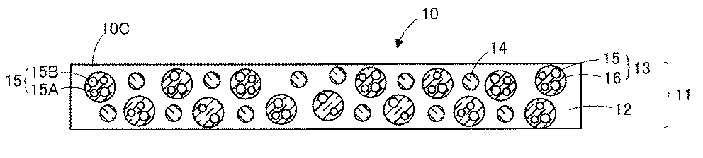
R1のアルキル基は直鎖状でも分岐状でもよい。R1のアルキル基としては、例えば、メチル基、エチル基、n−プロピル基、イソプロピル基、n−ブチル基、sec−ブチル基、イソブチル基、tert−ブチル基、n−ペンチル基、ネオペンチル基、tert−ペンチル基、イソペンチル基、2−メチルブチル基、1−エチルプロピル基、ヘキシル基、イソヘキシル基、4−メチルペンチル基、3−メチルペンチル基、2−メチルペンチル基、1−メチルペンチル基、3,3−ジメチルブチル基、2,2−ジメチルブチル基、1,1−ジメチルブチル基、1,2−ジメチルブチル基、1,3−ジメチルブチル基、2,3−ジメチルブチル基、1−エチルブチル基、2−エチルブチル基、ヘプチル基、オクチル基、ノニル基、デシル基等が挙げられる。 The alkyl group for R 1 may be linear or branched. Examples of the alkyl group for R 1 include methyl group, ethyl group, n-propyl group, isopropyl group, n-butyl group, sec-butyl group, isobutyl group, tert-butyl group, n-pentyl group, neopentyl group, tert-pentyl group, isopentyl group, 2-methylbutyl group, 1-ethylpropyl group, hexyl group, isohexyl group, 4-methylpentyl group, 3-methylpentyl group, 2-methylpentyl group, 1-methylpentyl group, 3 , 3-dimethylbutyl group, 2,2-dimethylbutyl group, 1,1-dimethylbutyl group, 1,2-dimethylbutyl group, 1,3-dimethylbutyl group, 2,3-dimethylbutyl group, 1-ethylbutyl Group, 2-ethylbutyl group, heptyl group, octyl group, nonyl group, decyl group and the like.
R2のアルキレン基は、直鎖状または分岐鎖状のいずれであってもよい。R2のアルキレン基としては、メチレン基、エチレン基、トリメチレン基、プロピレン基、イソプロピリデン基等が挙げられる。 The alkylene group for R 2 may be linear or branched. Examples of the alkylene group for R 2 include a methylene group, an ethylene group, a trimethylene group, a propylene group, and an isopropylidene group.
R1のアルキル基やR2のアルキレン基が置換されている場合、置換基としては、ハロゲン原子、水酸基、アルコキシ基、アリールオキシ基、アシル基、アルコキシカルボニル基、カルボキシル基、およびフェニル基等から選択される基が挙げられる。ハロゲン原子としては、フッ素原子、塩素原子、および臭素原子が挙げられる。 When the alkyl group of R 1 or the alkylene group of R 2 is substituted, examples of the substituent include a halogen atom, a hydroxyl group, an alkoxy group, an aryloxy group, an acyl group, an alkoxycarbonyl group, a carboxyl group, and a phenyl group. Examples include selected groups. Examples of the halogen atom include a fluorine atom, a chlorine atom, and a bromine atom.
R1のアルキル基中またはR2のアルキレン基中の1つのメチレン基または隣接しない2以上のメチレン基は、−O−、−S−、−SO2−、−CO−、−COO−、−OCO−、−NR4−、−CONR4−、−NR4CO−、−N=CH−および−CH=CH−からなる群から選択された少なくとも1つの基で置換されていてもよい(式中、R4はそれぞれ独立して水素又は炭素原子数1〜5のアルキル基を表す。) One methylene group or two or more non-adjacent methylene groups in the alkyl group of R 1 or the alkylene group of R 2 are —O—, —S—, —SO 2 —, —CO—, —COO—, — It may be substituted with at least one group selected from the group consisting of OCO—, —NR 4 —, —CONR 4 —, —NR 4 CO—, —N═CH— and —CH═CH— (formula In the formula, each R 4 independently represents hydrogen or an alkyl group having 1 to 5 carbon atoms.)
R3の脂肪族基に含まれても良い炭素原子以外の原子としては、例えば、窒素原子、酸素原子、硫黄原子等が挙げられる。 Examples of atoms other than carbon atoms that may be contained in the aliphatic group of R 3 include nitrogen atoms, oxygen atoms, and sulfur atoms.
これらのうち、光波長変換層の形成の際の硬化性や量子ドットの耐久性向上の観点から、R1が置換されていてもよい炭素原子数1〜5のアルキル基であり、R2が置換されていてもよい炭素原子数1〜5のアルキレン基であり、R3が炭素原子数1〜10の脂肪族基であり、mが1〜10であり、nが1〜15である2級チオール化合物が好ましい。ここでのR2のアルキレン基中の1つのメチレン基または隣接しない2以上のメチレン基も、上記と同様の基によって置換されていてもよい。 Among these, R 1 is an optionally substituted alkyl group having 1 to 5 carbon atoms from the viewpoint of improving curability at the time of forming the light wavelength conversion layer and durability of the quantum dots, and R 2 is 2 is an optionally substituted alkylene group having 1 to 5 carbon atoms, R 3 is an aliphatic group having 1 to 10 carbon atoms, m is 1 to 10, and n is 1 to 15. Grade thiol compounds are preferred. One methylene group or two or more methylene groups not adjacent to each other in the alkylene group represented by R 2 may be substituted with the same group as described above.
2級チオール化合物の具体例としては、1,4−ビス(3−メルカプトブチリルオキシ)ブタン、1,3,5−トリス(3−メルカプトブチルオキシエチル)−1,3,5−トリアジン−2,4,6(1H,3H,5H)−トリオン、ペンタエリスリトールテトラキス(3−メルカプトブチレート)、トリメチロールプロパントリス(3−メルカプトブチレート)、トリメチロールエタントリス(3−メルカプトブチレート)等が挙げられる。3級チオール化合物の具体例としては、tert−ブチルメルカプタン等が挙げられる。 Specific examples of the secondary thiol compound include 1,4-bis (3-mercaptobutyryloxy) butane, 1,3,5-tris (3-mercaptobutyloxyethyl) -1,3,5-triazine-2 , 4, 6 (1H, 3H, 5H) -trione, pentaerythritol tetrakis (3-mercaptobutyrate), trimethylolpropane tris (3-mercaptobutyrate), trimethylolethane tris (3-mercaptobutyrate), etc. Can be mentioned. Specific examples of the tertiary thiol compound include tert-butyl mercaptan.
<リン化合物>
リン化合物は、リンを含む化合物である。リン化合物としては、特に限定されないが、ホスホン酸系化合物、ホスフィン酸系化合物、ホスフィンオキサイド系化合物、亜ホスホン酸系化合物、亜ホスフィン酸系化合物、およびホスフィン系化合物が挙げられる。これらの中でも、光波長変換層の形成の際の硬化性や量子ドットの耐久性向上の観点から、下記一般式(2)で示される化合物が好ましい。
A phosphorus compound is a compound containing phosphorus. The phosphorus compound is not particularly limited, and examples thereof include phosphonic acid compounds, phosphinic acid compounds, phosphine oxide compounds, phosphonous acid compounds, phosphinic acid compounds, and phosphine compounds. Among these, the compound represented by the following general formula (2) is preferable from the viewpoint of improving curability when forming the light wavelength conversion layer and improving the durability of the quantum dots.
R5〜R7のいずれかが置換基を有している場合、置換基としては、ハロゲン原子(F、Cl、Br)、炭素数1〜6のアルキル基、炭素数1〜6のアルコキシ基、炭素数1〜6のアルケニル基、炭素数1〜6のアルキニル基、炭素数3〜6のシクロアルキル基、(メタ)アクリロイル基、(メタ)アクリロイルオキシ基、アミノ基、水酸基、カルボキシル基、炭素数1〜6のアルキルアミノ基、ニトロ基、フェニル基、ビフェニル基、ナフチル基、フェノキシ基、または複素環基等が挙げられる。 When any of R 5 to R 7 has a substituent, examples of the substituent include a halogen atom (F, Cl, Br), an alkyl group having 1 to 6 carbon atoms, and an alkoxy group having 1 to 6 carbon atoms. , An alkenyl group having 1 to 6 carbon atoms, an alkynyl group having 1 to 6 carbon atoms, a cycloalkyl group having 3 to 6 carbon atoms, a (meth) acryloyl group, a (meth) acryloyloxy group, an amino group, a hydroxyl group, a carboxyl group, Examples thereof include an alkylamino group having 1 to 6 carbon atoms, a nitro group, a phenyl group, a biphenyl group, a naphthyl group, a phenoxy group, or a heterocyclic group.
複素環基としては、ピリジル基、ピリミジニル基、ピリダジル基、ピラジル基、フリル基、チエニル基、オキサゾリル基、イソキサゾリル基、オキサジアゾリル基、チアゾリル基、イソチアゾリル基、イミダゾリル基、トリアゾリル基、ピロール基、ピラゾリル基、またはテトラゾリル基が挙げられる。 Heterocyclic groups include pyridyl, pyrimidinyl, pyridazyl, pyrazyl, furyl, thienyl, oxazolyl, isoxazolyl, oxadiazolyl, thiazolyl, isothiazolyl, imidazolyl, triazolyl, pyrrole, pyrazolyl Or a tetrazolyl group.
リン化合物としては、具体的には、トリス(2-エチルヘキシル)ホスファイト、トリラウリルホスファイト、トリス(トリデシル)ホスファイト、ビス(デシル)ペンタエリスリトールジホスファイト、ビス(トリデシル)ペンタエリスリトールジホスファイト、トリフェニルホスファイト、トリスノニルフェニルホスファイト、ブチルアシッドホスフェート、オレイルアシッドホスフェート、テトラコシルアシッドホスフェート、2-ヒドロキシエチルメタクリレートアシッドホスフェート、ジブチルホスフェート、ジメチルビニルホスフェート、ジ−2−エチルヘキシルハイドロゼンホスファイト、ジオレイルハイドロゼンホスファイト等が挙げられる。 Specific examples of phosphorus compounds include tris (2-ethylhexyl) phosphite, trilauryl phosphite, tris (tridecyl) phosphite, bis (decyl) pentaerythritol diphosphite, and bis (tridecyl) pentaerythritol diphosphite. , Triphenyl phosphite, trisnonyl phenyl phosphite, butyl acid phosphate, oleyl acid phosphate, tetracosyl acid phosphate, 2-hydroxyethyl methacrylate acid phosphate, dibutyl phosphate, dimethyl vinyl phosphate, di-2-ethylhexyl hydrogen phosphite And dioleyl hydrogen phosphite.
<窒素化合物>
窒素化合物は、窒素を含む化合物である。窒素化合物としては、特に限定されないが、光波長変換層の形成の際の硬化性や量子ドットの耐久性向上の観点から、アミン化合物が好ましい。アミン化合物としては、1級アミン化合物、2級アミン化合物および3級アミン化合物、ジアミン化合物のいずれであってもよい。
<Nitrogen compounds>
A nitrogen compound is a compound containing nitrogen. Although it does not specifically limit as a nitrogen compound, From a viewpoint of the sclerosis | hardenability at the time of formation of a light wavelength conversion layer, and the durable improvement of a quantum dot, an amine compound is preferable. As an amine compound, any of a primary amine compound, a secondary amine compound, a tertiary amine compound, and a diamine compound may be sufficient.
アミン化合物としては、具体的には、ラウリルアミン、ミリスチルアミン、セチルアミン、ステアリルアミン、オレイルアミン、ベヘニルアミン、ジステアリルアミン、ジメチルラウリルアミン、ジメチルミリスチルアミン、ジメチルステアリルアミン、ジラウリルモノメチルアミン、トリオクチルアミン、オレイルプロピレンジアミン等が挙げられる。 Specific examples of amine compounds include laurylamine, myristylamine, cetylamine, stearylamine, oleylamine, behenylamine, distearylamine, dimethyllaurylamine, dimethylmyristylamine, dimethylstearylamine, dilaurylmonomethylamine, and trioctylamine. And oleylpropylenediamine.
<重合性化合物>
重合性化合物は、第1の実施形態で説明した重合性化合物と同様であるので、下記以外は説明を省略するものとする。
<Polymerizable compound>
Since the polymerizable compound is the same as the polymerizable compound described in the first embodiment, the description is omitted except for the following.
光重合性化合物の中でも、耐久性をより向上させる観点から、水酸基およびカルボキシル基の少なくともいずれかを有する光重合性化合物が好ましい。水酸基やカルボキシル基は1分子中に少なくとも1以上あればよい。 Among the photopolymerizable compounds, a photopolymerizable compound having at least one of a hydroxyl group and a carboxyl group is preferable from the viewpoint of further improving durability. There may be at least one hydroxyl group or carboxyl group in one molecule.
水酸基を有する光重合性化合物としては、例えば2−ヒドロキシエチル(メタ)アクリレート、2−ヒドロキシプロピル(メタ)アクリレート、2−ヒドロキシ−3−フェノキシプロピル(メタ)アクリレート及び2−ヒドロキシブチル(メタ)アクリレート、4−ヒドロキシブチル(メタ)アクリレート、シクロヘキサンジメタノールモノ(メタ)アクリレート等のヒドロキシアルキル(メタ)アクリレート;グリセロールモノ(メタ)アクリレート、ポリエチレングリコールモノ(メタ)アクリレート、ポリプロピレングリコールモノ(メタ)アクリレート及びポリエチレングリコール−ポリプロピレングリコール共重合体のモノ(メタ)アクリレート化物等のポリアルキレングリコールモノ(メタ)アクリレート、ヒドロキシエチル(メタ)アクリルアミド、アリルアルコール、ペンタエリスリトールトリ(メタ)アクリレート等が挙げられる。 Examples of the photopolymerizable compound having a hydroxyl group include 2-hydroxyethyl (meth) acrylate, 2-hydroxypropyl (meth) acrylate, 2-hydroxy-3-phenoxypropyl (meth) acrylate, and 2-hydroxybutyl (meth) acrylate. Hydroxyalkyl (meth) acrylates such as 4-hydroxybutyl (meth) acrylate and cyclohexanedimethanol mono (meth) acrylate; glycerol mono (meth) acrylate, polyethylene glycol mono (meth) acrylate, polypropylene glycol mono (meth) acrylate and Polyalkylene glycol mono (meth) acrylates such as mono (meth) acrylates of polyethylene glycol-polypropylene glycol copolymers, hydroxyethyl ( Data) acrylamide, allyl alcohol, pentaerythritol tri (meth) acrylate.
カルボキシル基を有する光重合性化合物としては、(メタ)アクリル酸、クロトン酸、マレイン酸、フマル酸、イタコン酸、シトラコン酸、ケイヒ酸及び無水マレイン酸等の不飽和カルボン酸;イタコン酸モノエチルエステル、フマル酸モノブチルエステル及びマレイン酸モノブチルエステル等の不飽和ジカルボン酸のモノアルキルエステル;ω−カルボキシポリカプロラクトン(メタ)アクリレート、(メタ)アクリル酸ダイマー、2−(メタ)アクリロイロキシエチルフタル酸、2−(メタ)アクリロイロキシエチルヘキサヒドロフタル酸等のカルボキシル基含有(メタ)アクリレート等が挙げられる。 Examples of the photopolymerizable compound having a carboxyl group include unsaturated carboxylic acids such as (meth) acrylic acid, crotonic acid, maleic acid, fumaric acid, itaconic acid, citraconic acid, cinnamic acid and maleic anhydride; itaconic acid monoethyl ester Monoalkyl esters of unsaturated dicarboxylic acids such as monobutyl ester of fumaric acid and monobutyl maleate; ω-carboxypolycaprolactone (meth) acrylate, (meth) acrylic acid dimer, 2- (meth) acryloyloxyethylphthalate Examples include acids and carboxyl group-containing (meth) acrylates such as 2- (meth) acryloyloxyethyl hexahydrophthalic acid.
<<量子ドット>>
量子ドット137は量子ドット15と同様であるので、下記以外は、説明を省略するものとする。本実施形態の量子ドットはバリア粒子によって包まれていてもよいが、バリア粒子によって包まれていなくともよい。なお、図13に示される量子ドット137は、バリア粒子によって包まれていない。また、量子ドット137は、量子ドット15と同様に、第1の量子ドット137Aと、第1の量子ドット137Aとは異なる波長域の発光帯を有する第2の量子ドット137Bとを含んでいる。
<< Quantum dots >>
Since the
<光散乱性粒子>
光散乱性粒子134は光散乱性粒子18と同様であるので、ここでは説明を省略するものとする。
<Light scattering particles>
Since the light-scattering
<<光透過性基材>>
光透過性基材132、133の厚みは、特に限定されないが、10μm以上500μm以下であることが好ましい。光透過性基材132、133の厚みが、10μm未満であると、光波長変換シートのアッセンブリ、取扱い時における皺や折れが発生するおそれがあり、また150μmを超えると、ディスプレイの軽量化および薄膜化に適さないおそれがある。光透過性基材132、133の厚みのより好ましい下限は50μm以上、より好ましい上限は400μm以下である。
<< light transmissive substrate >>
The thickness of the light
光透過性基材132、133の平均厚みは、例えば、走査型電子顕微鏡(SEM)、透過型電子顕微鏡(TEM)又は走査透過型電子顕微鏡(STEM)で撮影した断面の画像を用いて算出できる。
The average thickness of the light-transmitting
光透過性基材132、133の構成材料としては、光透過性基材21の構成材料と同様のものが挙げられる。光透過性基材132、133は、単一の基材から構成されていてもよいが、複数の基材から構成される積層基材であってもよい。このような積層基材は、用途に応じて、同種の構成材料の層からなる複数の層から構成されていてもよく、異なる種類の構成材料の層からなる複数の層から構成されていてもよい。
Examples of the constituent material of the light
<<<光拡散層>>>
光拡散層134、135は、表面に凹凸形状を有しており、この凹凸形状によって光波長変換シート130に入射する光および出射する光を拡散させることができる。光拡散層14、15を設けることにより、光波長変換シート130における光波長変換効率をより高めることができる。光拡散層134、135は、表面凹凸形成粒子とバインダ樹脂とを含んでいる。
<<< Light diffusion layer >>>
The light diffusion layers 134 and 135 have a concavo-convex shape on the surface, and the light that enters and exits the light
<<表面凹凸形成粒子>>
表面凹凸形成粒子は、主に、光拡散層の表面に凹凸形状を形成するためのものである。ただし、表面凹凸形成粒子自体が光散乱性能を発揮することもある。
<< surface irregularity forming particle >>
The surface unevenness forming particles are mainly for forming an uneven shape on the surface of the light diffusion layer. However, the surface unevenness forming particles themselves may exhibit light scattering performance.
表面凹凸形成粒子の平均粒子径は、上述した量子ドット137の平均粒子径の10倍以上2万倍以下であることが好ましく、10〜5000倍であることがより好ましい。表面凹凸形成粒子の平均粒子径が量子ドットの平均粒子径の10倍未満であると、光拡散層に充分な光拡散性が得られないことがあり、また表面凹凸形成粒子の平均粒子径が量子ドットの平均粒子径の2万倍を超えると、光拡散層の光拡散性能は優れたものとなるが、光拡散層の光の透過率が大幅にダウンしやすくなる。なお、表面凹凸形成粒子の平均粒子径は、上述した量子ドットの平均粒子径と同様の方法で測定することができる。
The average particle diameter of the surface irregularity-forming particles is preferably 10 times or more and 20,000 times or less, more preferably 10 to 5000 times the average particle diameter of the
具体的には、表面凹凸形成粒子の平均粒子径は、例えば、1μm以上30μm以下であることが好ましく、1μm以上20μm以下であることがより好ましい。表面凹凸形成粒子の平均粒子径が1μm未満であると、光波長変換シートの光波長変換効率が不充分となることがあり、充分な光拡散性を出すためには表面凹凸形成粒子の添加量を多くする必要がある。一方、表面凹凸形成粒子の平均粒子径が30μmを超えると、光拡散性能は優れたものとなるが、光拡散層の光の透過率が大幅にダウンしやすくなる。 Specifically, the average particle diameter of the surface unevenness forming particles is, for example, preferably from 1 μm to 30 μm, and more preferably from 1 μm to 20 μm. If the average particle diameter of the surface irregularity-forming particles is less than 1 μm, the light wavelength conversion efficiency of the light wavelength conversion sheet may be insufficient, and the amount of addition of the surface irregularity-forming particles is sufficient to provide sufficient light diffusibility. Need to be more. On the other hand, when the average particle diameter of the surface irregularity-forming particles exceeds 30 μm, the light diffusion performance is excellent, but the light transmittance of the light diffusion layer is likely to be greatly reduced.
表面凹凸形成粒子とバインダ樹脂との屈折率差の絶対値は、0.02以上0.15以下であることが好ましい。0.02未満であると、光学的に表面凹凸形成粒子の持つ屈折率による光拡散性が得られず、光波長変換シートの光波長変換効率の向上が不充分となることがあり、0.15を超えると、光拡散層の透過率が低下してしまうことがある。表面凹凸形成粒子とバインダ樹脂との屈折率差のより好ましい下限は0.03以上、より好ましい上限は0.12以下である。なお、表面凹凸形成粒子の屈折率とバインダ樹脂の屈折率とは、いずれの方が大きくてもよい。表面凹凸形成粒子およびバインダ樹脂の屈折率は、光散乱性粒子18および第1のバインダ樹脂の屈折率と同様の手法によって測定することができる。 The absolute value of the refractive index difference between the surface unevenness forming particles and the binder resin is preferably 0.02 or more and 0.15 or less. If it is less than 0.02, the light diffusibility due to the refractive index of the surface irregularity-forming particles cannot be optically obtained, and the improvement of the light wavelength conversion efficiency of the light wavelength conversion sheet may be insufficient. If it exceeds 15, the transmittance of the light diffusion layer may be lowered. The more preferable lower limit of the refractive index difference between the surface unevenness forming particles and the binder resin is 0.03 or more, and the more preferable upper limit is 0.12 or less. Note that either the refractive index of the surface irregularity-forming particles and the refractive index of the binder resin may be larger. The refractive indexes of the surface unevenness forming particles and the binder resin can be measured by the same technique as the refractive indexes of the light scattering particles 18 and the first binder resin.
表面凹凸形成粒子の形状は特に限定されず、例えば、球状(真球状、略真球状、楕円球状等)、多面体状、棒状(円柱状、角柱状等)、平板状、りん片状、不定形状等が挙げられる。なお、表面凹凸形成粒子の粒子径は、表面凹凸形成粒子の形状が球状でない場合、同体積を有する真球状の値とすることができる。 The shape of the surface irregularity-forming particles is not particularly limited. For example, spherical (true sphere, approximately true sphere, elliptic sphere, etc.), polyhedron, rod (column, prismatic, etc.), flat plate, flake, irregular shape Etc. In addition, when the shape of the surface unevenness forming particles is not spherical, the particle size of the surface unevenness forming particles can be a true spherical value having the same volume.
表面凹凸形成粒子は、表面凹凸形成粒子をバインダ樹脂中に強固に固定する観点から、バインダ樹脂と化学結合していることが好ましい。この化学結合は、シランカップリング剤で表面修飾された表面凹凸形成粒子を用いることによって実現できる。シランカップリング剤は、光散乱性粒子の欄で説明したシランカップリング剤と同様であるので、ここでは説明を省略するものとする。 The surface irregularity-forming particles are preferably chemically bonded to the binder resin from the viewpoint of firmly fixing the surface irregularity-forming particles in the binder resin. This chemical bond can be realized by using surface irregularity-forming particles whose surface is modified with a silane coupling agent. Since the silane coupling agent is the same as the silane coupling agent described in the column of light scattering particles, the description thereof is omitted here.
表面凹凸形成粒子は、有機材料からなる粒子または無機材料からなる粒子であってもよい。表面凹凸形成粒子を構成する有機材料としては特に限定されず、例えば、ポリエステル、ポリスチレン、メラミン樹脂、(メタ)アクリル樹脂、アクリル−スチレン共重合体樹脂、シリコーン樹脂、ベンゾグアナミン樹脂、ベンゾグアナミン・ホルムアルデヒド縮合樹脂、ポリカーボネート、ポリエチレン、ポリオレフィン等が挙げられる。なかでも、架橋アクリル樹脂が好適に用いられる。また、上記光拡散粒子を構成する無機材料としては特に限定されず、例えば、シリカ、アルミナ、チタニア、酸化スズ、アンチモンドープ酸化スズ(ATO)、酸化亜鉛微粒子等の無機酸化物等が挙げられる。なかでも、シリカ及び/又はアルミナが好適に用いられる。 The surface irregularity-forming particles may be particles made of an organic material or particles made of an inorganic material. The organic material constituting the surface irregularity-forming particles is not particularly limited. For example, polyester, polystyrene, melamine resin, (meth) acrylic resin, acrylic-styrene copolymer resin, silicone resin, benzoguanamine resin, benzoguanamine / formaldehyde condensation resin , Polycarbonate, polyethylene, polyolefin and the like. Of these, a crosslinked acrylic resin is preferably used. Moreover, it does not specifically limit as an inorganic material which comprises the said light-diffusion particle | grains, For example, inorganic oxides, such as a silica, an alumina, a titania, a tin oxide, an antimony dope tin oxide (ATO), a zinc oxide fine particle, etc. are mentioned. Of these, silica and / or alumina is preferably used.
<<バインダ樹脂>>
バインダ樹脂としては、特に限定されないが、バインダ樹脂12の欄で説明した重合性化合物の硬化物(重合物、架橋物)を用いることができるので、ここでは説明を省略するものとする。
<< Binder resin >>
Although it does not specifically limit as binder resin, Since the hardened | cured material (polymerized material, crosslinked material) of the polymeric compound demonstrated in the column of
<<<他の光波長変換シート>>>
本実施形態に係る光波長変換シートは、第1の実施形態に係る光波長変換シート10、20、40、50の光波長変換層11を光波長変換層131に代えた光波長変換シートであってもよい。なお、光波長変換シート40においては、光波長変換層11と光制御シート41が接着層42を介して貼り合わせられているが、光制御シートに光波長変換層用組成物を直接塗布、硬化させることによって光波長変換層131と光制御シートとを直接接合してもよい。また、光波長変換シート30の光波長変換層31のようにレンズ部を備えた光波長変換シートであってもよい。この場合、これらの光波長変換シートにおいては、シート全体で、40℃、相対湿度90%での水蒸気透過率が0.1g/(m2・24h)以上および/または23℃、相対湿度90%での酸素透過率が0.1cm3/(m2・24h・atm)以上となっていてもよい。また、これらの光波長変換シートにおいては、40℃、相対湿度90%での水蒸気透過率は1g/(m2・24h)以上となっていてもよく、また光波長変換シートにおける23℃、相対湿度90%での酸素透過率が1cm3/(m2・24h・atm)以上となっていてもよい。さらに、これらの光波長変換シートにおいても、60℃、相対湿度90%の環境下に500時間放置する耐久性試験の前後において、光波長変換シートの一方の表面の全面に量子ドットによって波長変換される所定の光量の光を照射して、光波長変換シートの他方の表面の中央部から出射する光の輝度を測定したとき、耐久性試験前の光波長変換シートの他方の表面の中央部から出射する光の輝度に対する耐久性試験後の光波長変換シートの他方の表面の中央部から出射する光の輝度の変化率が±10%以内となっていることが好ましく、±5%以内であることがより好ましい。また、これらの光波長変換シートにおいても、60℃、相対湿度90%の環境下に500時間放置する耐久性試験を行ったとき、耐久性試験後の光波長変換シートにおける周縁部の劣化幅が5mm以下となることが好ましく、3mm以下となることがより好ましい。
<<< Other Light Wavelength Conversion Sheet >>>
The light wavelength conversion sheet according to this embodiment is a light wavelength conversion sheet obtained by replacing the light
<<<光波長変換シートの製造方法>>>
光波長変換シート130は、例えば、以下のようにして作製することができる。まず、図示しないが、光透過性基材132の一方の面に、表面凹凸形成粒子および硬化性バインダ樹脂前駆体を含む光拡散層用組成物を塗布し、乾燥させて、光拡散層用組成物の塗膜を形成する。また、同様に、光透過性基材133の一方の面に、光拡散層用組成物の塗膜を形成する。
<<< Method for Producing Light Wavelength Conversion Sheet >>>
The light
次いで、電離放射線照射等によって、光拡散層用組成物の塗膜を硬化させる。これにより、図14(A)に示されるように、光透過性基材132の一方の面に光拡散層134が形成されて、光拡散層134付き光透過性基材132が形成される。また、図示しないが、同様にして、光拡散層135付き光透過性基材133を形成する。
Subsequently, the coating film of the composition for light diffusion layers is hardened by ionizing radiation irradiation etc. Thereby, as shown in FIG. 14A, the
光拡散層135付き光透過性基材133を形成した後、図14(B)に示されるように、光拡散層135付き光透過性基材133における光拡散層135側の面とは反対側の面に、量子ドット137、上記特定の化合物ならびに重合性化合物を含む硬化性バインダ樹脂前駆体、ならびに光散乱性粒子138を含む光波長変換層用組成物を塗布し、乾燥させて、光波長変換層用組成物の塗膜139を形成する。
After forming the
光波長変換層用組成物の全固形分質量に対する量子ドットの含有量は、0.01質量%以上2質量%以下であることが好ましく、0.03質量%以上1質量%以下であることがより好ましい。量子ドットの含有量が0.01質量%未満であると、充分な発光強度が得られないおそれがあり、また、量子ドットの含有量が2質量%を超えると、充分な励起光の透過光強度が得られないおそれがある。 The content of the quantum dots with respect to the total solid mass of the composition for the light wavelength conversion layer is preferably 0.01% by mass or more and 2% by mass or less, and preferably 0.03% by mass or more and 1% by mass or less. More preferred. If the content of quantum dots is less than 0.01% by mass, sufficient emission intensity may not be obtained. If the content of quantum dots exceeds 2% by mass, sufficient transmitted light of excitation light is transmitted. There is a risk that strength cannot be obtained.
光波長変換層用組成物の全固形分質量に対する上記特定の化合物の含有量は、5質量%以上となっている。特定の化合物の含有量が5質量%未満であると、量子ドットの劣化を抑制できないおそれがある。光波長変換層用組成物の全固形分質量に対する特定の化合物の含有量の下限は10質量%以上であることがより好ましく、また特定の化合物の含有量の上限は70質量%以下であることが好ましく、50質量%以下であることがより好ましい。光波長変換層用組成物の全固形分質量に対する特定の化合物の含有量が70質量%を越えると、光波長変換層の形成の際に充分な硬化性が得られないおそれがある。なお、光波長変換層用組成物が2種以上の特定の化合物を含む場合には、上記含有量は特定の化合物の合計の含有量を意味するものとする。 Content of the said specific compound with respect to the total solid content mass of the composition for optical wavelength conversion layers is 5 mass% or more. If the content of the specific compound is less than 5% by mass, deterioration of the quantum dots may not be suppressed. The lower limit of the content of the specific compound with respect to the total solid mass of the composition for the light wavelength conversion layer is more preferably 10% by mass or more, and the upper limit of the content of the specific compound is 70% by mass or less. Is preferable, and it is more preferable that it is 50 mass% or less. When the content of the specific compound with respect to the total solid content of the composition for the light wavelength conversion layer exceeds 70% by mass, sufficient curability may not be obtained when the light wavelength conversion layer is formed. In addition, when the composition for light wavelength conversion layers contains 2 or more types of specific compounds, the said content shall mean the total content of a specific compound.
光波長変換層用組成物の全固形分質量に対する重合性化合物の含有量は、30質量%以上95質量%以下であることが好ましく、50質量%以上90質量%以下であることが好ましい。重合性化合物の含有量が30質量%未満であると、光波長変換層の形成の際に充分な硬化性が得られないおそれがあり、また、重合性化合物の含有量が95質量%を超えると、上記特定の化合物による耐久性向上の効果が充分に得られないおそれがある。なお、光波長変換層用組成物が光重合性化合物および熱重合性化合物の両方を含む場合には、上記含有量は光重合性化合物および熱重合性化合物の合計の含有量を意味するものとする。 The content of the polymerizable compound with respect to the total solid mass of the composition for light wavelength conversion layer is preferably 30% by mass to 95% by mass, and more preferably 50% by mass to 90% by mass. If the content of the polymerizable compound is less than 30% by mass, sufficient curability may not be obtained when forming the light wavelength conversion layer, and the content of the polymerizable compound exceeds 95% by mass. And there exists a possibility that the effect of the durable improvement by the said specific compound may not fully be acquired. In addition, when the composition for light wavelength conversion layers contains both the photopolymerizable compound and the thermopolymerizable compound, the above content means the total content of the photopolymerizable compound and the thermopolymerizable compound. To do.
光波長変換層用組成物の全固形分質量に対する光散乱性粒子18の含有量は、1質量%以上50質量%以下であることが好ましく、3質量%以上30質量%以下であることがより好ましい。光散乱性粒子の含有量が1質量%未満であると、光散乱効果が充分に得られないおそれがあり、また、光散乱性粒子の含有量が50質量%を超えると、ミー散乱が起こり難くなるので、光散乱効果を充分に得られないおそれがあり、さらに光散乱性粒子が多すぎるために加工性が低下するおそれがある。 The content of the light scattering particles 18 with respect to the total solid mass of the composition for a light wavelength conversion layer is preferably 1% by mass or more and 50% by mass or less, and more preferably 3% by mass or more and 30% by mass or less. preferable. If the content of the light scattering particles is less than 1% by mass, the light scattering effect may not be sufficiently obtained, and if the content of the light scattering particles exceeds 50% by mass, Mie scattering occurs. Since it becomes difficult, the light scattering effect may not be sufficiently obtained, and the processability may be deteriorated because there are too many light scattering particles.
光波長変換層用組成物は重合開始剤を含んでいることが好ましい。重合開始剤は、第1の実施形態と同様のものであるので、ここでは説明を省略するものとする。 It is preferable that the composition for light wavelength conversion layers contains the polymerization initiator. Since the polymerization initiator is the same as that in the first embodiment, the description thereof is omitted here.
光波長変換層用組成物の塗膜139形成後、図15(A)に示されるように光拡散層14付き光透過性基材132における光拡散層134側の面とは反対側の面が光波長変換層用組成物の塗膜139と接するように、光波長変換層用組成物の塗膜139上に光拡散層134付き光透過性基材132を配置する。これにより、光波長変換層用組成物の塗膜139が、光透過性基材132、133間で挟まれる。
After the
次いで、図15(B)に示されるように光透過性基材132を介して光波長変換層用組成物の塗膜139に電離放射線を照射して、または熱を加えて、硬化性バインダ樹脂前駆体を硬化させて、光波長変換層131を形成するとともに、光波長変換層131と、光拡散層134付き光透過性基材132および光拡散層145付き光透過性基材133とを一体化させる。これにより、図13に示される光波長変換シート130が得られる。
Next, as shown in FIG. 15 (B), the
本実施形態によれば、第1の実施形態と同様に、光波長変換シート130における40℃、相対湿度90%での水蒸気透過率が0.1g/(m2・24h)以上および/または光波長変換シート130における23℃、相対湿度90%での酸素透過率が0.1cm3/(m2・24h・atm)以上となっているので、光透過性基材およびバリア層からなるバリアフィルムを備えていない。したがって、バリアフィルムに起因するピンホールやクラックが発生することがなく、これにより、点状の輝度欠点を抑制することができる。また、光波長変換層131が量子ドット137の劣化抑制機能を有しているので、バリアフィルムを備えていなくとも、量子ドット137の劣化を抑制できる。さらに、光波長変換シート130においては、バリアフィルムを備えていないので、薄型化および製造コストの低減を図ることができる。
According to this embodiment, as in the first embodiment, the water vapor transmission rate at 40 ° C. and 90% relative humidity in the light
量子ドットの劣化の原因は、チオールやホスフィン等からなる量子ドットの表面に配位するリガンドが量子ドットから光や熱で脱離してしまうことにより量子ドットが酸化され易くなることにあると考えられる。本実施形態によれば、蛍光X線分析により測定される光波長変換層131中の上記特定の元素の含有量は、0.5質量%以上となっているので、量子ドット137の劣化を抑制できる。これは、リガンドが量子ドット137から脱離した場合であっても、バインダ樹脂136に含まれ、かつ量子ドット137の周辺に存在する硫黄成分、リン成分、または窒素成分がリガンドの役割を補助するような機能(例えば、リガンドの代わりに量子ドット137に結合して、リガンドを代替する機能)を発揮するからであると考えられる。これにより、耐久性を向上させることができ、かつ周縁部130C(図13参照)に存在する量子ドット137の劣化を抑制できる。また、蛍光X線分析により測定される光波長変換層131中の上記特定の元素の含有量を0.5質量%以上とすることにより、光波長変換層131に量子ドット137の劣化抑制機能を付与することができる。
The cause of the deterioration of the quantum dots is considered to be that the ligands coordinated on the surface of the quantum dots made of thiol, phosphine, etc. are desorbed from the quantum dots by light or heat, so that the quantum dots are easily oxidized. . According to the present embodiment, since the content of the specific element in the light
また、本実施形態によれば、蛍光X線分析により測定される光波長変換層131中の硫黄元素の含有量を0.5質量%以上として、量子ドット137の劣化を抑制しているので、光波長変換シート130における40℃、相対湿度90%での水蒸気透過率が0.1g/(m2・24h)以上および/または光波長変換シート130における23℃、相対湿度90%での酸素透過率が0.1cm3/(m2・24h・atm)以上であったとしても、別途バリアフィルムを設ける必要がない。これにより、光波長変換シートの工程を簡素化できることにより品質を良化させやすくなるとともに、光波長変換シートの薄型化および製造コストの低減を図ることができる。
Moreover, according to this embodiment, since the content of the sulfur element in the light
また、光波長変換層用組成物が光波長変換層用組成物の全固形分質量に対して5質量%以上の上記特定の化合物を含んでいるので、量子ドットの劣化を抑制できる。これにより、本実施形態の光波長変換層用組成物を用いて、耐久性を向上させることができ、かつ周縁部130Cに存在する量子ドット137の劣化を抑制できる光波長変換層131を形成することができる。
Moreover, since the composition for optical wavelength conversion layers contains 5 mass% or more of the said specific compound with respect to the total solid content mass of the composition for optical wavelength conversion layers, deterioration of a quantum dot can be suppressed. Thereby, the optical
本実施形態によれば、光波長変換シート130における40℃、相対湿度90%での水蒸気透過率が0.1g/(m2・24h)以上および/または23℃、相対湿度90%での酸素透過率が0.1cm3/(m2・24h・atm)以上であったとしても、光波長変換シート130を60℃、相対湿度90%の環境下に500時間放置する耐久性試験の前後において、耐久性試験前の光波長変換シート130の表面の中央部から出射する光の輝度に対する耐久性試験後の光波長変換シート130の表面の中央部から出射する光の輝度の変化率が±10%以内となっている場合には、光波長変換シート130の中心部の劣化を抑制できる。また、この場合には、60℃、相対湿度90%の環境下に500時間放置する耐久性試験後の光波長変換シート130における周縁部の劣化幅を5mm以下とすることができる。これにより、バリアフィルムを設けなくとも、光波長変換シート130の中心部および周縁部の劣化を抑制することができる。
According to the present embodiment, the light transmittance of the light
本実施形態における光波長変換シートも、第1の実施形態で説明したバックライト装置70、120や画像表示装置60と同様の構造のバックライト装置や画像表示装置に組み込むことが可能である。
The light wavelength conversion sheet in the present embodiment can also be incorporated into a backlight device or an image display device having the same structure as the
本発明を詳細に説明するために、以下に実施例を挙げて説明するが、本発明はこれらの記載に限定されない。 In order to describe the present invention in detail, examples will be described below, but the present invention is not limited to these descriptions.
<光波長変換粒子の作製>
まず、下記に示す手順で、光波長変換粒子を得た。
(光波長変換粒子1)
まず、0.2質量部の緑色発光量子ドット(製品名「CdSe/ZnS 530」、SIGMA−ALDRICH社製、コア:CdSe、シェル:ZnS、平均粒子径3.3nm)および0.2質量部の赤色発光量子ドット(製品名「CdSe/ZnS 610」、SIGMA−ALDRICH社製、コア:CdSe、シェル:ZnS、平均粒子径5.2nm)を用意した。緑色発光量子ドットおよび赤色発光量子ドットを用意した後、緑色発光量子ドットおよび赤色発光量子ドットの表面をドデシルアミンで覆い、これらの量子ドットをトルエン溶液(0.4mL、1.5μM/L)に分散させた。次いで、この溶液にテトラエトキシシラン(TEOS、10μL)を添加し、3時間攪拌して、有機溶液1を作製した。
<Preparation of light wavelength conversion particles>
First, light wavelength conversion particles were obtained by the procedure shown below.
(Light wavelength conversion particle 1)
First, 0.2 parts by mass of green light emitting quantum dots (product name “CdSe / ZnS 530”, manufactured by SIGMA-ALDRICH, core: CdSe, shell: ZnS, average particle diameter: 3.3 nm) and 0.2 parts by mass Red light-emitting quantum dots (product name “CdSe / ZnS 610”, manufactured by SIGMA-ALDRICH, core: CdSe, shell: ZnS, average particle diameter: 5.2 nm) were prepared. After preparing the green light emission quantum dot and the red light emission quantum dot, the surface of the green light emission quantum dot and the red light emission quantum dot is covered with dodecylamine, and these quantum dots are added to a toluene solution (0.4 mL, 1.5 μM / L). Dispersed. Next, tetraethoxysilane (TEOS, 10 μL) was added to this solution and stirred for 3 hours to prepare an organic solution 1.
一方で、3−メルカプトプロピルトリメトキシシラン(MPS、1μL)をエタノール(25mL)とアンモニア水(4mL、アンモニア濃度10wt%)に混合して水溶液2を作製した。
Meanwhile, 3-mercaptopropyltrimethoxysilane (MPS, 1 μL) was mixed with ethanol (25 mL) and aqueous ammonia (4 mL,
そして、有機溶液1と水溶液2を混合し、3時間攪拌したところ、緑色発光量子ドットおよび赤色発光量子ドットは水相に移動し、さらに水相で緑色発光量子ドットおよび赤色発光量子ドットの集合体が形成された。この集合体を遠心分離によって取り出した。 Then, when the organic solution 1 and the aqueous solution 2 are mixed and stirred for 3 hours, the green light-emitting quantum dots and the red light-emitting quantum dots move to the aqueous phase, and further, an aggregate of the green light-emitting quantum dots and the red light-emitting quantum dots in the aqueous phase. Formed. This assembly was removed by centrifugation.
最後に、上記の集合体が分散した水溶液0.5mLを取り出し、エタノール(8mL)とアンモニア水(0.1mL、25wt%)を加え、さらにTEOS(14μL)を添加した。これにより、緑色発光量子ドットおよび赤色発光量子ドットからなる集合体がシリカガラスで包まれ、平均粒子径50nmの光波長変換粒子1を得た。 Finally, 0.5 mL of the aqueous solution in which the aggregate was dispersed was taken out, ethanol (8 mL) and aqueous ammonia (0.1 mL, 25 wt%) were added, and TEOS (14 μL) was further added. Thereby, the aggregate | assembly consisting of a green light emission quantum dot and a red light emission quantum dot was wrapped with silica glass, and the light wavelength conversion particle | grains 1 with an average particle diameter of 50 nm were obtained.
(光波長変換粒子2)
まず、0.2質量部の緑色発光量子ドット(製品名「CdSe/ZnS 530」、SIGMA−ALDRICH社製、コア:CdSe、シェル:ZnS、平均粒子径3.3nm)を用意する。緑色発光量子ドットを用意した後、緑色発光量子ドットの表面をドデシルアミンで覆い、緑色発光量子ドットをトルエン溶液(0.4mL、1.5μM/L)に分散させた。次いで、この溶液にテトラエトキシシラン(TEOS、10μL)を添加し、3時間攪拌して、有機溶液3を得た。
(Light wavelength conversion particle 2)
First, 0.2 parts by mass of green light emitting quantum dots (product name “CdSe / ZnS 530”, manufactured by SIGMA-ALDRICH, core: CdSe, shell: ZnS, average particle diameter: 3.3 nm) are prepared. After preparing the green light emitting quantum dots, the surface of the green light emitting quantum dots was covered with dodecylamine, and the green light emitting quantum dots were dispersed in a toluene solution (0.4 mL, 1.5 μM / L). Next, tetraethoxysilane (TEOS, 10 μL) was added to this solution and stirred for 3 hours to obtain an organic solution 3.
そして、有機溶液3と実施例1で作製した水溶液2を混合し、3時間攪拌したところ、緑色発光量子ドットは水相に移動し、さらに水相で緑色発光量子ドットの集合体が形成された。この集合体を遠心分離によって取り出した。 Then, when the organic solution 3 and the aqueous solution 2 prepared in Example 1 were mixed and stirred for 3 hours, the green light-emitting quantum dots moved to the aqueous phase, and an aggregate of green light-emitting quantum dots was formed in the aqueous phase. . This assembly was removed by centrifugation.
最後に、上記の集合体が分散した水溶液0.5mLを取り出し、エタノール(8mL)とアンモニア水(0.1mL、25wt%)を加え、さらにTEOS(14μL)を添加した。これにより、緑色発光量子ドットからなる集合体がシリカガラスで包まれ、緑色発光量子ドットを含む平均粒子径50nmの光波長変換粒子2を得た。 Finally, 0.5 mL of the aqueous solution in which the aggregate was dispersed was taken out, ethanol (8 mL) and aqueous ammonia (0.1 mL, 25 wt%) were added, and TEOS (14 μL) was further added. Thereby, the aggregate | assembly which consists of a green light emission quantum dot was wrapped with silica glass, and the light wavelength conversion particle | grains 2 with an average particle diameter of 50 nm containing a green light emission quantum dot were obtained.
(光波長変換粒子3)
まず、0.2質量部の赤色発光量子ドット(製品名「CdSe/ZnS 610」、SIGMA−ALDRICH社製、コア:CdSe、シェル:ZnS、平均粒子径5.2nm)を用意する。赤色発光量子ドットを用意した後、赤色発光量子ドットの表面をドデシルアミンで覆い、赤色光り発光量子ドットをトルエン溶液(0.4mL、1.5μM/L)に分散させた。次いで、この溶液にテトラエトキシシラン(TEOS、10μL)を添加し、3時間攪拌して、有機溶液4を得た。
(Light wavelength conversion particle 3)
First, 0.2 parts by mass of red light emitting quantum dots (product name “CdSe / ZnS 610”, manufactured by SIGMA-ALDRICH, core: CdSe, shell: ZnS, average particle diameter: 5.2 nm) are prepared. After preparing red light emitting quantum dots, the surface of the red light emitting quantum dots was covered with dodecylamine, and the red light emitting quantum dots were dispersed in a toluene solution (0.4 mL, 1.5 μM / L). Next, tetraethoxysilane (TEOS, 10 μL) was added to this solution and stirred for 3 hours to obtain an organic solution 4.
そして、有機溶液4と実施例1で作製した水溶液2を混合し、3時間攪拌したところ、赤色発光量子ドットは水相に移動し、さらに水相で赤色発光量子ドットの集合体が形成された。この集合体を遠心分離によって取り出した。 Then, when the organic solution 4 and the aqueous solution 2 prepared in Example 1 were mixed and stirred for 3 hours, the red light-emitting quantum dots moved to the water phase, and an aggregate of red light-emitting quantum dots was formed in the water phase. . This assembly was removed by centrifugation.
最後に、上記の集合体が分散した水溶液0.5mLを取り出し、エタノール(8mL)とアンモニア水(0.1mL、25wt%)を加え、さらにTEOS(14μL)を添加した。これにより、赤色発光量子ドットからなる集合体をシリカガラスで包み、赤色発光量子ドットを含む平均粒子径50nmの光波長変換粒子3を得た。 Finally, 0.5 mL of the aqueous solution in which the aggregate was dispersed was taken out, ethanol (8 mL) and aqueous ammonia (0.1 mL, 25 wt%) were added, and TEOS (14 μL) was further added. Thereby, the aggregate | assembly which consists of a red light emission quantum dot was wrapped with silica glass, and the light wavelength conversion particle 3 with an average particle diameter of 50 nm containing a red light emission quantum dot was obtained.
<光波長変換シート用組成物の調製>
まず、下記に示す組成となるように各成分を配合して、光波長変換層用組成物を得た。
(光波長変換層用組成物1)
・エポキシアクリレート(製品名「ユニディックV−5500」、DIC社製):99質量部
・光波長変換粒子1:5質量部
・アルミナ粒子(光散乱性粒子、製品名「DAM−03」、電気化学工業社製、平均粒子径4μm):10質量部
・光重合開始剤(1−ヒドロキシシクロヘキシルフェニルケトン、製品名「Irgacure(登録商標)184」、BASFジャパン社製):1質量部
<Preparation of composition for light wavelength conversion sheet>
First, each component was mix | blended so that it might become a composition shown below, and the composition for optical wavelength conversion layers was obtained.
(Composition 1 for light wavelength conversion layer)
Epoxy acrylate (product name “Unidic V-5500”, manufactured by DIC Corporation): 99 parts by mass • Light wavelength conversion particles 1: 5 parts by mass • Alumina particles (light scattering particles, product name “DAM-03”, electricity Chemical Industry Co., Ltd., average particle size 4 μm): 10 parts by mass Photoinitiator (1-hydroxycyclohexyl phenyl ketone, product name “Irgacure (registered trademark) 184”, manufactured by BASF Japan): 1 part by mass
(光波長変換層用組成物2)
・エポキシアクリレート(製品名「ユニディックV−5500」、DIC社製):99質量部
・光波長変換粒子2:2.5質量部
・光波長変換粒子3:2.5質量部
・アルミナ粒子(光散乱性粒子、製品名「DAM−03」、電気化学工業社製、平均粒子径4μm):10質量部
・光重合開始剤(1−ヒドロキシシクロヘキシルフェニルケトン、製品名「Irgacure(登録商標)184」、BASFジャパン社製):1質量部
(Composition 2 for light wavelength conversion layer)
-Epoxy acrylate (product name "Unidic V-5500", manufactured by DIC Corporation): 99 parts by mass-Light wavelength conversion particles 2: 2.5 parts by mass-Light wavelength conversion particles 3: 2.5 parts by mass-Alumina particles ( Light-scattering particles, product name “DAM-03”, manufactured by Denki Kagaku Kogyo Co., Ltd., average particle size 4 μm): 10 parts by mass / photopolymerization initiator (1-hydroxycyclohexyl phenyl ketone, product name “Irgacure (registered trademark) 184” ", Manufactured by BASF Japan Ltd.): 1 part by mass
(光波長変換層用組成物3)
・エポキシアクリレート(製品名「ユニディックV−5500」、DIC社製):89質量部
・緑色発光量子ドット(製品名「CdSe/ZnS 530」、SIGMA−ALDRICH社製、コア:CdSe、シェル:ZnS、平均粒子径3.3nm):0.20質量部
・赤色発光量子ドット(製品名「CdSe/ZnS 610」、SIGMA−ALDRICH社製、コア:CdSe、シェル:ZnS、平均粒子径5.2nm):0.20質量部
・アルミナ粒子(光散乱性粒子、製品名「DAM−03」、電気化学工業社製、平均粒子径4μm):10質量部
・光重合開始剤(1−ヒドロキシシクロヘキシルフェニルケトン、製品名「Irgacure(登録商標)184」、BASFジャパン社製):1質量部
(Composition 3 for light wavelength conversion layer)
Epoxy acrylate (product name “Unidic V-5500”, manufactured by DIC): 89 parts by mass Green emitting quantum dot (product name “CdSe / ZnS 530”, manufactured by SIGMA-ALDRICH, core: CdSe, shell: ZnS , Average particle diameter 3.3 nm): 0.20 parts by mass / red light emitting quantum dot (product name “CdSe / ZnS 610”, manufactured by SIGMA-ALDRICH, core: CdSe, shell: ZnS, average particle diameter 5.2 nm) : 0.20 parts by mass / alumina particles (light scattering particles, product name “DAM-03”, manufactured by Denki Kagaku Kogyo Co., Ltd., average particle size 4 μm): 10 parts by mass / photopolymerization initiator (1-hydroxycyclohexyl phenyl ketone) , Product name “Irgacure (registered trademark) 184”, manufactured by BASF Japan Ltd.): 1 part by mass
(光波長変換層用組成物4)
・エポキシアクリレート(製品名「ユニディックV−5500」、DIC社製):90質量部
・トリメチロールプロパントリス(3−メルカプトブチレート)(製品名「TPMB」、昭和電工社製):10質量部
・緑色発光量子ドット(製品名「CdSe/ZnS 530」、SIGMA−ALDRICH社製、コア:CdSe、シェル:ZnS、平均粒径3.3nm):0.20質量部
・赤色発光量子ドット(製品名「CdSe/ZnS 610」、SIGMA−ALDRICH社製、コア:CdSe、シェル:ZnS、平均粒径5.2nm):0.20質量部
・ラジカル重合開始剤(1−ヒドロキシシクロヘキシルフェニルケトン、製品名「Irgacure(登録商標)184」、BASFジャパン社製):0.2質量部
(Composition 4 for light wavelength conversion layer)
Epoxy acrylate (product name “Unidic V-5500”, manufactured by DIC): 90 parts by mass Trimethylolpropane tris (3-mercaptobutyrate) (product name “TPMB”, manufactured by Showa Denko KK): 10 parts by mass Green light emitting quantum dots (product name “CdSe / ZnS 530”, manufactured by SIGMA-ALDRICH, core: CdSe, shell: ZnS, average particle size 3.3 nm): 0.20 parts by mass Red light emitting quantum dots (product name “CdSe / ZnS 610”, manufactured by SIGMA-ALDRICH, core: CdSe, shell: ZnS, average particle diameter 5.2 nm): 0.20 part by mass / radical polymerization initiator (1-hydroxycyclohexyl phenyl ketone, product name “ Irgacure (registered trademark) 184 ", manufactured by BASF Japan Ltd.): 0.2 parts by mass
(光波長変換層用組成物5)
・エポキシアクリレート(製品名「ユニディックV−5500」、DIC社製):90質量部
・トリメチロールプロパントリス(3−メルカプトブチレート)(製品名「TPMB」、昭和電工社製):10質量部
・緑色発光量子ドット(製品名「CdSe/ZnS 530」、SIGMA−ALDRICH社製、コア:CdSe、シェル:ZnS、平均粒径3.3nm):0.20質量部
・赤色発光量子ドット(製品名「CdSe/ZnS 610」、SIGMA−ALDRICH社製、コア:CdSe、シェル:ZnS、平均粒径5.2nm):0.20質量部
・アルミナ粒子(光散乱性粒子、製品名「DAM−03」、電気化学工業社製、平均粒子径4μm):10質量部
・ラジカル重合開始剤(1−ヒドロキシシクロヘキシルフェニルケトン、製品名「Irgacure(登録商標)184」、BASFジャパン社製):0.2質量部
(Composition 5 for light wavelength conversion layer)
Epoxy acrylate (product name “Unidic V-5500”, manufactured by DIC): 90 parts by mass Trimethylolpropane tris (3-mercaptobutyrate) (product name “TPMB”, manufactured by Showa Denko KK): 10 parts by mass Green light emitting quantum dots (product name “CdSe / ZnS 530”, manufactured by SIGMA-ALDRICH, core: CdSe, shell: ZnS, average particle size 3.3 nm): 0.20 parts by mass Red light emitting quantum dots (product name “CdSe / ZnS 610”, manufactured by SIGMA-ALDRICH, core: CdSe, shell: ZnS, average particle size 5.2 nm): 0.20 parts by mass / alumina particles (light scattering particles, product name “DAM-03”) , Manufactured by Denki Kagaku Kogyo Co., Ltd., average particle size 4 μm): 10 parts by mass / radical polymerization initiator (1-hydroxycyclohexyl phenyl keto Product name “Irgacure (registered trademark) 184” manufactured by BASF Japan Ltd.): 0.2 parts by mass
(光波長変換層用組成物6)
・エポキシアクリレート(製品名「ユニディックV−5500」、DIC社製):90質量部
・2−メタクロイロキシエチルアシッドホスフェート(製品名「ライトエステルP−2M」、共栄社化学社製):10質量部
・緑色発光量子ドット(製品名「CdSe/ZnS 530」、SIGMA−ALDRICH社製、コア:CdSe、シェル:ZnS、平均粒径3.3nm):0.20質量部
・赤色発光量子ドット(製品名「CdSe/ZnS 610」、SIGMA−ALDRICH社製、コア:CdSe、シェル:ZnS、平均粒径5.2nm):0.20質量部
・アルミナ粒子(光散乱性粒子、製品名「DAM−03」、電気化学工業社製、平均粒子径4μm):10質量部
・ラジカル重合開始剤(1−ヒドロキシシクロヘキシルフェニルケトン、製品名「Irgacure(登録商標)184」、BASFジャパン社製):0.2質量部
(Composition 6 for light wavelength conversion layer)
-Epoxy acrylate (product name "Unidic V-5500", manufactured by DIC Corporation): 90 parts by mass-2-methacryloxyethyl acid phosphate (product name "Light Ester P-2M", manufactured by Kyoeisha Chemical Co., Ltd.): 10 masses Part / green light-emitting quantum dot (product name “CdSe / ZnS 530”, manufactured by SIGMA-ALDRICH, core: CdSe, shell: ZnS, average particle size 3.3 nm): 0.20 part by mass / red light-emitting quantum dot (product Name “CdSe / ZnS 610”, manufactured by SIGMA-ALDRICH, core: CdSe, shell: ZnS, average particle size 5.2 nm): 0.20 parts by mass / alumina particles (light scattering particles, product name “DAM-03”) ”, Manufactured by Denki Kagaku Kogyo Co., Ltd., average particle size: 4 μm): 10 parts by mass / radical polymerization initiator (1-hydroxycyclohexylpheny Luketone, product name “Irgacure (registered trademark) 184” manufactured by BASF Japan Ltd.): 0.2 parts by mass
(光波長変換層用組成物7)
・エポキシアクリレート(製品名「ユニディックV−5500」、DIC社製):90質量部
・ステアリルアミン(製品名「ファーミン80」、花王社製):10質量部
・緑色発光量子ドット(製品名「CdSe/ZnS 530」、SIGMA−ALDRICH社製、コア:CdSe、シェル:ZnS、平均粒径3.3nm):0.20質量部
・赤色発光量子ドット(製品名「CdSe/ZnS 610」、SIGMA−ALDRICH社製、コア:CdSe、シェル:ZnS、平均粒径5.2nm):0.20質量部
・アルミナ粒子(光散乱性粒子、製品名「DAM−03」、電気化学工業社製、平均粒子径4μm):10質量部
・ラジカル重合開始剤(1−ヒドロキシシクロヘキシルフェニルケトン、製品名「Irgacure(登録商標)184」、BASFジャパン社製):0.2質量部
(Composition 7 for light wavelength conversion layer)
-Epoxy acrylate (product name "Unidic V-5500", manufactured by DIC): 90 parts by mass-Stearylamine (product name "
(光波長変換層用組成物8)
・エポキシアクリレート(製品名「ユニディックV−5500」、DIC社製):90質量部
・トリメチロールプロパントリス(3−メルカプトブチレート)(製品名「TPMB」、昭和電工社製):5質量部
・2−メタクロイロキシエチルアシッドホスフェート(製品名「ライトエステルP−2M」、共栄社化学社製):5質量部
・緑色発光量子ドット(製品名「CdSe/ZnS 530」、SIGMA−ALDRICH社製、コア:CdSe、シェル:ZnS、平均粒径3.3nm):0.20質量部
・赤色発光量子ドット(製品名「CdSe/ZnS 610」、SIGMA−ALDRICH社製、コア:CdSe、シェル:ZnS、平均粒径5.2nm):0.20質量部
・アルミナ粒子(光散乱性粒子、製品名「DAM−03」、電気化学工業社製、平均粒子径4μm):10質量部
・ラジカル重合開始剤(1−ヒドロキシシクロヘキシルフェニルケトン、製品名「Irgacure(登録商標)184」、BASFジャパン社製):0.2質量部
(Composition 8 for light wavelength conversion layer)
Epoxy acrylate (product name “Unidic V-5500”, manufactured by DIC): 90 parts by mass Trimethylolpropane tris (3-mercaptobutyrate) (product name “TPMB”, manufactured by Showa Denko KK): 5 parts by mass -2-methacryloylethyl acid phosphate (product name "light ester P-2M", manufactured by Kyoeisha Chemical Co., Ltd.): 5 parts by mass-green light emitting quantum dot (product name "CdSe / ZnS 530", manufactured by SIGMA-ALDRICH, Core: CdSe, shell: ZnS, average particle size: 3.3 nm): 0.20 parts by mass. Red light emitting quantum dot (product name “CdSe / ZnS 610”, manufactured by SIGMA-ALDRICH, core: CdSe, shell: ZnS, (Average particle diameter 5.2 nm): 0.20 parts by mass / alumina particles (light scattering particles, product name “DAM-03”) Gas Chemical Industries, Ltd., average particle size 4 [mu] m): 10 parts by mass polymerization initiator (1-hydroxycyclohexyl phenyl ketone, product name "Irgacure (registered trademark) 184" manufactured by BASF Japan Ltd.): 0.2 parts by weight
(光波長変換層用組成物9)
・エポキシアクリレート(製品名「ユニディックV−5500」、DIC社製):75質量部
・トリメチロールプロパントリス(3−メルカプトブチレート)(製品名「TPMB」、昭和電工社製):25質量部
・緑色発光量子ドット(製品名「CdSe/ZnS 530」、SIGMA−ALDRICH社製、コア:CdSe、シェル:ZnS、平均粒径3.3nm):0.20質量部
・赤色発光量子ドット(製品名「CdSe/ZnS 610」、SIGMA−ALDRICH社製、コア:CdSe、シェル:ZnS、平均粒径5.2nm):0.20質量部
・アルミナ粒子(光散乱性粒子、製品名「DAM−03」、電気化学工業社製、平均粒子径4μm):10質量部
・ラジカル重合開始剤(1−ヒドロキシシクロヘキシルフェニルケトン、製品名「Irgacure(登録商標)184」、BASFジャパン社製):0.2質量部
(Composition 9 for light wavelength conversion layer)
Epoxy acrylate (product name “Unidic V-5500”, manufactured by DIC): 75 parts by mass Trimethylolpropane tris (3-mercaptobutyrate) (product name “TPMB”, manufactured by Showa Denko KK): 25 parts by mass Green light emitting quantum dots (product name “CdSe / ZnS 530”, manufactured by SIGMA-ALDRICH, core: CdSe, shell: ZnS, average particle size 3.3 nm): 0.20 parts by mass Red light emitting quantum dots (product name “CdSe / ZnS 610”, manufactured by SIGMA-ALDRICH, core: CdSe, shell: ZnS, average particle size 5.2 nm): 0.20 parts by mass / alumina particles (light scattering particles, product name “DAM-03”) , Manufactured by Denki Kagaku Kogyo Co., Ltd., average particle size 4 μm): 10 parts by mass / radical polymerization initiator (1-hydroxycyclohexyl phenyl keto Product name “Irgacure (registered trademark) 184” manufactured by BASF Japan Ltd.): 0.2 parts by mass
(光波長変換層用組成物10)
・エポキシアクリレート(製品名「ユニディックV−5500」、DIC社製):50質量部
・トリメチロールプロパントリス(3−メルカプトブチレート)(製品名「TPMB」、昭和電工社製):50質量部
・緑色発光量子ドット(製品名「CdSe/ZnS 530」、SIGMA−ALDRICH社製、コア:CdSe、シェル:ZnS、平均粒径3.3nm):0.20質量部
・赤色発光量子ドット(製品名「CdSe/ZnS 610」、SIGMA−ALDRICH社製、コア:CdSe、シェル:ZnS、平均粒径5.2nm):0.20質量部
・アルミナ粒子(光散乱性粒子、製品名「DAM−03」、電気化学工業社製、平均粒子径4μm):10質量部
・ラジカル重合開始剤(1−ヒドロキシシクロヘキシルフェニルケトン、製品名「Irgacure(登録商標)184」、BASFジャパン社製):0.2質量部
(
Epoxy acrylate (product name “Unidic V-5500”, manufactured by DIC Corporation): 50 parts by mass Trimethylolpropane tris (3-mercaptobutyrate) (product name “TPMB”, manufactured by Showa Denko KK): 50 parts by mass Green light emitting quantum dots (product name “CdSe / ZnS 530”, manufactured by SIGMA-ALDRICH, core: CdSe, shell: ZnS, average particle size 3.3 nm): 0.20 parts by mass Red light emitting quantum dots (product name “CdSe / ZnS 610”, manufactured by SIGMA-ALDRICH, core: CdSe, shell: ZnS, average particle size 5.2 nm): 0.20 parts by mass / alumina particles (light scattering particles, product name “DAM-03”) , Manufactured by Denki Kagaku Kogyo Co., Ltd., average particle size 4 μm): 10 parts by mass / radical polymerization initiator (1-hydroxycyclohexyl phenyl keto Product name “Irgacure (registered trademark) 184” manufactured by BASF Japan Ltd.): 0.2 parts by mass
(光波長変換層用組成物11)
・エポキシアクリレート(製品名「ユニディックV−5500」、DIC社製):100質量部
・緑色発光量子ドット(製品名「CdSe/ZnS 530」、SIGMA−ALDRICH社製、コア:CdSe、シェル:ZnS、平均粒径3.3nm):0.20質量部
・赤色発光量子ドット(製品名「CdSe/ZnS 610」、SIGMA−ALDRICH社製、コア:CdSe、シェル:ZnS、平均粒径5.2nm):0.20質量部
・ラジカル重合開始剤(1−ヒドロキシシクロヘキシルフェニルケトン、製品名「Irgacure(登録商標)184」、BASFジャパン社製):0.2質量部
(
Epoxy acrylate (product name “Unidick V-5500”, manufactured by DIC): 100 parts by mass Green emitting quantum dot (product name “CdSe / ZnS 530”, manufactured by SIGMA-ALDRICH, core: CdSe, shell: ZnS , Average particle size 3.3 nm): 0.20 parts by mass Red-emitting quantum dots (product name “CdSe / ZnS 610”, manufactured by SIGMA-ALDRICH, core: CdSe, shell: ZnS, average particle size 5.2 nm) : 0.20 parts by mass. Radical polymerization initiator (1-hydroxycyclohexyl phenyl ketone, product name “Irgacure (registered trademark) 184”, manufactured by BASF Japan Ltd.): 0.2 parts by mass
(光波長変換層用組成物12)
・エポキシアクリレート(製品名「ユニディックV−5500」、DIC社製):97質量部
・トリメチロールプロパントリス(3−メルカプトブチレート)(製品名「TPMB」、昭和電工社製):3質量部
・緑色発光量子ドット(製品名「CdSe/ZnS 530」、SIGMA−ALDRICH社製、コア:CdSe、シェル:ZnS、平均粒径3.3nm):0.20質量部
・赤色発光量子ドット(製品名「CdSe/ZnS 610」、SIGMA−ALDRICH社製、コア:CdSe、シェル:ZnS、平均粒径5.2nm):0.20質量部
・ラジカル重合開始剤(1−ヒドロキシシクロヘキシルフェニルケトン、製品名「Irgacure(登録商標)184」、BASFジャパン社製):0.2質量部
(
Epoxy acrylate (product name “Unidic V-5500”, manufactured by DIC): 97 parts by mass Trimethylolpropane tris (3-mercaptobutyrate) (product name “TPMB”, manufactured by Showa Denko KK): 3 parts by mass Green light emitting quantum dots (product name “CdSe / ZnS 530”, manufactured by SIGMA-ALDRICH, core: CdSe, shell: ZnS, average particle size 3.3 nm): 0.20 parts by mass Red light emitting quantum dots (product name “CdSe / ZnS 610”, manufactured by SIGMA-ALDRICH, core: CdSe, shell: ZnS, average particle diameter 5.2 nm): 0.20 part by mass / radical polymerization initiator (1-hydroxycyclohexyl phenyl ketone, product name “ Irgacure (registered trademark) 184 ", manufactured by BASF Japan Ltd.): 0.2 parts by mass
<オーバーコート層用組成物の調製>
下記に示す組成となるように各成分を配合して、オーバーコート層用組成物を得た。
(オーバーコート層用組成物1)
・アクリル酸亜鉛(製品名「ZN−DA」日本触媒社製):30質量部
・メタノール:70質量部
・光重合開始剤(1−ヒドロキシシクロヘキシルフェニルケトン、製品名「Irgacure(登録商標)184、BASFジャパン社製):1質量部
<Preparation of composition for overcoat layer>
Each component was mix | blended so that it might become a composition shown below, and the composition for overcoat layers was obtained.
(Composition 1 for overcoat layer)
Zinc acrylate (product name “ZN-DA” manufactured by Nippon Shokubai Co., Ltd.): 30 parts by mass Methanol: 70 parts by mass Photopolymerization initiator (1-hydroxycyclohexyl phenyl ketone, product name “Irgacure (registered trademark) 184, BASF Japan)): 1 part by mass
(オーバーコート層用組成物2)
・ジペンタエリスリトールヘキサアクリレートとジペンタエリスリトールペンタアクリレートの混合物(製品名「アロニックス(登録商標)M−403」、東亞合成社製):30質量部
・メタノール:70質量部
・光重合開始剤(1−ヒドロキシシクロヘキシルフェニルケトン、製品名「Irgacure(登録商標)184、BASFジャパン社製):1質量部
(Composition 2 for overcoat layer)
-Mixture of dipentaerythritol hexaacrylate and dipentaerythritol pentaacrylate (product name "Aronix (registered trademark) M-403", manufactured by Toagosei Co., Ltd.): 30 parts by mass-Methanol: 70 parts by mass-Photopolymerization initiator (1 -Hydroxycyclohexyl phenyl ketone, product name “Irgacure (registered trademark) 184, manufactured by BASF Japan Ltd.”: 1 part by mass
<光拡散層用組成物の調製>
下記に示す組成となるように各成分を配合して、光拡散層用組成物1を得た。
(光拡散層用組成物1)
・ペンタエリスリトールトリアクリレート:99質量部
・表面凹凸形成粒子(架橋ポリスチレン樹脂ビーズ、製品名「SBX−4」、積水化成品工業株式会社製、平均粒子径4μm):158質量部
・光重合開始剤(1−ヒドロキシシクロヘキシルフェニルケトン、製品名「Irgacure(登録商標)184、BASFジャパン社製):1質量部
・溶剤(メチルイソブチルケトン:シクロヘキサノン=1:1(質量比)):170質量部
<Preparation of composition for light diffusion layer>
Each component was mix | blended so that it might become a composition shown below, and the composition 1 for light diffusion layers was obtained.
(Composition 1 for light diffusion layer)
Pentaerythritol triacrylate: 99 parts by mass Surface irregularity-forming particles (crosslinked polystyrene resin beads, product name “SBX-4”, manufactured by Sekisui Plastics Co., Ltd., average particle size 4 μm): 158 parts by mass Photopolymerization initiator (1-hydroxycyclohexyl phenyl ketone, product name “Irgacure (registered trademark) 184, manufactured by BASF Japan Ltd.): 1 part by mass / solvent (methyl isobutyl ketone: cyclohexanone = 1: 1 (mass ratio)): 170 parts by mass
<実施例1>
まず、厚さ50μmのポリエチレンテレフタレート(PET)基材(製品名「ルミラーT60」、東レ社製)の一方の面に光波長変換層用組成物1を塗布し、塗膜を形成した。そして、紫外線を積算光量が500mJ/cm2になるように照射して塗膜を硬化させて、光波長変換層を得た。最後に、PET基材を剥離し、実施例1に係る厚さ100μmの光波長変換層のみからなる光波長変換シートを形成した。なお、光波長変換シートの厚みは、光波長変換シートの断面を、走査型電子顕微鏡(SEM)を用いて撮影し、その断面の画像において光波長変換シートの厚みを20箇所測定し、その20箇所の厚みの平均値とした。
<Example 1>
First, the composition 1 for light wavelength conversion layer was apply | coated to one side of a 50-micrometer-thick polyethylene terephthalate (PET) base material (product name "Lumirror T60", Toray Industries, Inc. make), and the coating film was formed. And the ultraviolet-ray was irradiated so that an integrated light quantity might be set to 500 mJ / cm < 2 >, the coating film was hardened, and the light wavelength conversion layer was obtained. Finally, the PET base material was peeled off to form a light wavelength conversion sheet consisting only of a light wavelength conversion layer having a thickness of 100 μm according to Example 1. The thickness of the light wavelength conversion sheet was obtained by taking a cross-section of the light wavelength conversion sheet using a scanning electron microscope (SEM) and measuring the thickness of the light wavelength conversion sheet at 20 locations in the cross-sectional image. It was set as the average value of the thickness of a location.
<実施例2>
実施例2においては、光波長変換層用組成物1の代わりに光波長変換層用組成物2を用いたこと以外は、実施例1と同様にして、光波長変換シートを作製した。
<Example 2>
In Example 2, a light wavelength conversion sheet was produced in the same manner as in Example 1 except that the light wavelength conversion layer composition 2 was used instead of the light wavelength conversion layer composition 1.
<実施例3>
実施例3においては、光波長変換層からPET基材を剥離しなかったこと以外は、実施例1と同様にして、光波長変換シートを作製した。実施例3に係る光波長変換シートは、光波長変換シートとPET基材からなるものであった。実施例3に係る光波長変換シートの厚みは140μmであった。
<Example 3>
In Example 3, a light wavelength conversion sheet was produced in the same manner as in Example 1 except that the PET base material was not peeled from the light wavelength conversion layer. The light wavelength conversion sheet according to Example 3 was composed of a light wavelength conversion sheet and a PET base material. The thickness of the light wavelength conversion sheet according to Example 3 was 140 μm.
<実施例4>
実施例4においては、光波長変換層からPET基材を剥離しなかったこと以外は、実施例2と同様にして、光波長変換シートを作製した。実施例4に係る光波長変換シートは、光波長変換シートとPET基材からなるものであった。
<Example 4>
In Example 4, a light wavelength conversion sheet was produced in the same manner as in Example 2 except that the PET base material was not peeled from the light wavelength conversion layer. The light wavelength conversion sheet according to Example 4 was composed of a light wavelength conversion sheet and a PET base material.
<実施例5>
所望の単位プリズムの形状に対し逆形状の凹部を有し、かつ回転する成形用型に光波長変換層用組成物1を塗工充填し、次いでこれにポリエチレンテレフタレート(PET)基材(製品名「ルミラーT60」、東レ社製)を走行速度10m/分で供給して型面の光波長変換層用組成物1の上から成形用型に押圧した。そして、押圧した状態で、PET基材を介して光波長変換層用組成物1に紫外線を照射して光波長変換層用組成物1を硬化させた。そして、硬化させた光波長変換層用組成物1をPET基材と共に回転する成形用型から剥離して、レンズ部を有する光波長変換層を得た。レンズ部は、シート状の本体部と、この本体部上に並べて配置され、かつ各々が配列方向と交差する方向に延びており、頂角が90°であり、幅が50μmであり、高さが25μmである複数の三角柱状の単位プリズムを有していた。最後に、光波長変換層からPET基材を剥離して、レンズ部を有し、かつ光波長変換層のみからなる光波長変換シートを得た。実施例5に係る光波長変換シートの厚みは125μmであった。
<Example 5>
The composition for light wavelength conversion layer 1 is coated and filled in a mold having a concave shape opposite to the desired unit prism shape and rotating, and then a polyethylene terephthalate (PET) substrate (product name) “Lumirror T60” (manufactured by Toray Industries, Inc.) was supplied at a traveling speed of 10 m / min and pressed onto the mold from above the composition 1 for the light wavelength conversion layer on the mold surface. And in the pressed state, the composition 1 for light wavelength conversion layers was irradiated with the ultraviolet-ray through the PET base material, and the composition 1 for light wavelength conversion layers was hardened. And the hardened composition 1 for light wavelength conversion layers was peeled from the shaping | molding type | mold which rotates with a PET base material, and the light wavelength conversion layer which has a lens part was obtained. The lens part is arranged side by side on the sheet-like main body part and extends in a direction intersecting the arrangement direction, the apex angle is 90 °, the width is 50 μm, and the height. Has a plurality of triangular prism unit prisms. Finally, the PET base material was peeled from the light wavelength conversion layer to obtain a light wavelength conversion sheet having a lens portion and consisting only of the light wavelength conversion layer. The thickness of the light wavelength conversion sheet according to Example 5 was 125 μm.
<実施例6>
実施例6においては、光波長変換層用組成物1の代わりに光波長変換層用組成物2を用いたこと以外は、実施例5と同様にして、光波長変換シートを作製した。
<Example 6>
In Example 6, a light wavelength conversion sheet was produced in the same manner as in Example 5 except that the composition 2 for light wavelength conversion layer was used instead of the composition 1 for light wavelength conversion layer.
<実施例7>
まず、プリズムシートを用意した。プリズムシートは以下のようにして作製された。所望の単位プリズムの形状に対し逆形状の凹部を有し、かつ回転する成形用型にエポキシアクリレート(製品名「ユニディックV−5500」、DIC社製)99質量部に光重合開始剤(1−ヒドロキシシクロヘキシルフェニルケトン、製品名「Irgacure(登録商標)184」、BASFジャパン社製)1質量部を含むプリズム層用組成物を塗工充填し、次いでこれに厚さ50μmの光透過性基材としてのポリエチレンテレフタレート(PET)基材(製品名「ルミラーT60」、東レ社製)を走行速度10m/分で供給して型面のプリズム層用組成物の上から成形用型に押圧した。そして、押圧した状態で、PET基材を介してプリズム層用組成物に紫外線を照射してプリズム層用組成物を硬化させた。そして、硬化させたプリズム層用組成物をPET基材と共に回転する成形用型から剥離して、プリズムシートを得た。プリズムシートは、シート状の本体部と、この本体部上に並べて配置され、かつ各々が配列方向と交差する方向に延びており、頂角が90°であり、幅が50μmであり、高さが25μmである複数の三角柱状の単位プリズムを有していた。
<Example 7>
First, a prism sheet was prepared. The prism sheet was produced as follows. A photopolymerization initiator (1) having 99 parts by mass of epoxy acrylate (product name “Unidic V-5500”, manufactured by DIC) having a concave part having a reverse shape with respect to the shape of a desired unit prism and rotating. -Hydroxycyclohexyl phenyl ketone, product name “Irgacure (registered trademark) 184” (manufactured by BASF Japan Ltd.) is coated and filled with a composition for a prism layer containing 1 part by mass, and then a light-transmitting substrate having a thickness of 50 μm A polyethylene terephthalate (PET) base material (product name “Lumirror T60”, manufactured by Toray Industries, Inc.) was supplied at a traveling speed of 10 m / min and pressed onto the molding die from the prism layer composition on the mold surface. Then, in the pressed state, the prism layer composition was cured by irradiating the prism layer composition with ultraviolet rays through a PET substrate. Then, the cured composition for the prism layer was peeled off from the mold for rotation together with the PET substrate to obtain a prism sheet. The prism sheet has a sheet-like main body, and is arranged side by side on the main body, and each extends in a direction intersecting the arrangement direction. The apex angle is 90 °, the width is 50 μm, and the height. Has a plurality of triangular prism unit prisms.
プリズムシートのレンズ面とは反対側の面に、紫外線硬化性接着剤を介して、実施例1に係る光波長変換シート(光波長変換層)を配置した。そして、プリズムシート側から、紫外線を積算光量が500mJ/cm2になるように照射して紫外線硬化性接着剤を硬化させて、光波長変換層、接着層、プリズムシートからなる光波長変換シートを得た。実施例7に係る光波長変換シートの厚みは180μmであった。 The light wavelength conversion sheet (light wavelength conversion layer) according to Example 1 was disposed on the surface of the prism sheet opposite to the lens surface via an ultraviolet curable adhesive. Then, from the prism sheet side, ultraviolet light is irradiated so that the integrated light quantity becomes 500 mJ / cm 2 to cure the ultraviolet curable adhesive, and the light wavelength conversion sheet comprising the light wavelength conversion layer, the adhesive layer, and the prism sheet is obtained. Obtained. The thickness of the light wavelength conversion sheet according to Example 7 was 180 μm.
<実施例8>
実施例8においては、実施例1に係る光波長変換シートの代わりに実施例2に係る光波長変換シートを用いたこと以外は、実施例7と同様にして、光波長変換シートを作製した。
<Example 8>
In Example 8, a light wavelength conversion sheet was produced in the same manner as in Example 7 except that the light wavelength conversion sheet according to Example 2 was used instead of the light wavelength conversion sheet according to Example 1.
<実施例9>
実施例7と同様の手順に沿って作製され、かつ実施例7と同じ大きさのプリズムシートのレンズ面とは反対側の面に、光波長変換層用組成物1を塗布し、塗膜を形成した。そして、紫外線を積算光量が500mJ/cm2になるように照射して塗膜を硬化させて、光波長変換層を得た。これにより、光波長変換シートおよびプリズムシートからなる光波長変換シートを得た。実施例9に係る光波長変換シートの厚みは175μmであった。
<Example 9>
The composition for light wavelength conversion layer 1 was applied to the surface opposite to the lens surface of the prism sheet having the same size as that of Example 7 prepared in the same manner as in Example 7, and the coating film was coated. Formed. And the ultraviolet-ray was irradiated so that an integrated light quantity might be set to 500 mJ / cm < 2 >, the coating film was hardened, and the light wavelength conversion layer was obtained. This obtained the light wavelength conversion sheet which consists of a light wavelength conversion sheet and a prism sheet. The thickness of the light wavelength conversion sheet according to Example 9 was 175 μm.
<実施例10>
実施例10においては、光波長変換層用組成物1の代わりに光波長変換層用組成物2を用いたこと以外は、実施例9と同様にして、光波長変換シートを作製した。
<Example 10>
In Example 10, a light wavelength conversion sheet was produced in the same manner as in Example 9 except that the light wavelength conversion layer composition 2 was used instead of the light wavelength conversion layer composition 1.
<実施例11>
まず、PET基材の一方の面に光波長変換層用組成物1を塗布し、塗膜を形成した。そして、実施例7と同様の手順に沿って作製され、かつ実施例7と同じ大きさのプリズムシートのレンズ面とは反対側の面に塗膜が接するように塗膜付きポリエチレンテレフタレート(PET)基材(製品名「ルミラーT60」、東レ社製)を配置した。そして、紫外線を積算光量が500mJ/cm2になるように照射して塗膜を硬化させて、光波長変換層を得た。最後に、PET基材を剥離し、光波長変換シートおよびプリズムシートからなる光波長変換シートを得た。実施例11に係る光波長変換シートの厚みは175μmであった。
<Example 11>
First, the composition 1 for light wavelength conversion layer was apply | coated to one side of a PET base material, and the coating film was formed. Then, a polyethylene terephthalate (PET) with a coating film is produced according to the same procedure as in Example 7 and the coating film is in contact with the surface opposite to the lens surface of the prism sheet having the same size as in Example 7. A base material (product name “Lumirror T60”, manufactured by Toray Industries, Inc.) was placed. And the ultraviolet-ray was irradiated so that an integrated light quantity might be set to 500 mJ / cm < 2 >, the coating film was hardened, and the light wavelength conversion layer was obtained. Finally, the PET substrate was peeled off to obtain a light wavelength conversion sheet comprising a light wavelength conversion sheet and a prism sheet. The thickness of the light wavelength conversion sheet according to Example 11 was 175 μm.
<実施例12>
実施例12においては、光波長変換層用組成物1の代わりに光波長変換層用組成物2を用いたこと以外は、実施例11と同様にして、光波長変換シートを作製した。
<Example 12>
In Example 12, a light wavelength conversion sheet was produced in the same manner as in Example 11 except that the light wavelength conversion layer composition 2 was used instead of the light wavelength conversion layer composition 1.
<実施例13>
実施例1で作製した光波長変換層(光波長変換層)の一方の面に、オーバーコート層用組成物1を塗布し、塗膜を形成した。そして、紫外線を積算光量が500mJ/cm2になるように照射して塗膜を硬化させて、膜厚5μmのオーバーコート層を得た。次いで、同様に、光波長変換層の他方の面に、オーバーコート層用組成物1を塗布し、塗膜を形成した。そして、紫外線を積算光量が500mJ/cm2になるように照射して塗膜を硬化させて、膜厚5μmのオーバーコート層を得た。これにより、光波長変換層と、光波長変換層の両面に形成されたオーバーコート層とからなる光波長変換シートを得た。
<Example 13>
The overcoat layer composition 1 was applied to one surface of the light wavelength conversion layer (light wavelength conversion layer) prepared in Example 1 to form a coating film. And the ultraviolet-ray was irradiated so that an integrated light quantity might be set to 500 mJ / cm < 2 >, the coating film was hardened, and the overcoat layer with a film thickness of 5 micrometers was obtained. Next, similarly, overcoat layer composition 1 was applied to the other surface of the light wavelength conversion layer to form a coating film. And the ultraviolet-ray was irradiated so that an integrated light quantity might be set to 500 mJ / cm < 2 >, the coating film was hardened, and the overcoat layer with a film thickness of 5 micrometers was obtained. This obtained the light wavelength conversion sheet which consists of a light wavelength conversion layer and the overcoat layer formed in both surfaces of the light wavelength conversion layer.
<実施例14>
実施例14においては、オーバーコート層用組成物1の代わりにオーバーコート層用組成物2を用いたこと以外は、実施例13と同様にして、光波長変換シートを作製した。
<Example 14>
In Example 14, a light wavelength conversion sheet was produced in the same manner as in Example 13 except that the overcoat layer composition 2 was used instead of the overcoat layer composition 1.
<比較例1>
比較例1においては、光波長変換層用組成物1の代わりに光波長変換層用組成物3を用いたこと以外は、実施例1と同様にして、光波長変換シートを作製した。
<Comparative Example 1>
In Comparative Example 1, a light wavelength conversion sheet was produced in the same manner as in Example 1 except that the composition 3 for light wavelength conversion layer was used instead of the composition 1 for light wavelength conversion layer.
<比較例2>
比較例2においては、光波長変換層用組成物1の代わりに光波長変換層用組成物3を用いたこと以外は、実施例3と同様にして、光波長変換シートを作製した。
<Comparative example 2>
In Comparative Example 2, a light wavelength conversion sheet was produced in the same manner as in Example 3 except that the composition 3 for light wavelength conversion layer was used instead of the composition 1 for light wavelength conversion layer.
<比較例3>
比較例3においては、光波長変換層用組成物1の代わりに光波長変換層用組成物3を用いたこと以外は、実施例5と同様にして、光波長変換シートを作製した。
<Comparative Example 3>
In Comparative Example 3, a light wavelength conversion sheet was produced in the same manner as in Example 5 except that the composition 3 for light wavelength conversion layer was used instead of the composition 1 for light wavelength conversion layer.
<比較例4>
比較例4においては、光波長変換層用組成物1の代わりに光波長変換層用組成物3を用いたこと以外は、実施例7と同様にして、光波長変換シートを作製した。
<Comparative example 4>
In Comparative Example 4, a light wavelength conversion sheet was produced in the same manner as in Example 7 except that the light wavelength conversion layer composition 3 was used instead of the light wavelength conversion layer composition 1.
<比較例5>
比較例5においては、光波長変換層用組成物1の代わりに光波長変換層用組成物3を用いたこと以外は、実施例9と同様にして、光波長変換シートを作製した。
<Comparative Example 5>
In Comparative Example 5, a light wavelength conversion sheet was produced in the same manner as in Example 9 except that the light wavelength conversion layer composition 3 was used instead of the light wavelength conversion layer composition 1.
<比較例6>
比較例6においては、光波長変換層用組成物1の代わりに光波長変換層用組成物3を用いたこと以外は、実施例11と同様にして、光波長変換シートを作製した。
<Comparative Example 6>
In Comparative Example 6, a light wavelength conversion sheet was produced in the same manner as in Example 11 except that the composition 3 for light wavelength conversion layer was used instead of the composition 1 for light wavelength conversion layer.
<比較例7>
比較例7においは、光波長変換層用組成物1の代わりに光波長変換層用組成物3を用いたこと以外は、実施例13と同様にして、光波長変換シートを作製した。
<Comparative Example 7>
In Comparative Example 7, a light wavelength conversion sheet was produced in the same manner as in Example 13 except that the composition 3 for light wavelength conversion layer was used instead of the composition 1 for light wavelength conversion layer.
<比較例8>
まず、2枚のバリアフィルムを次のような方法で作製した。高周波スパッタリング装置において、電極に周波数13.56MHz、電力5kWの高周波電力を印加することにより、チャンバー内で放電を生じさせて、ポリエチレンテレフタレート(PET)基材(製品名「ルミラーT60」、東レ社製)の片面にターゲット物質(シリカ)からなる、厚みが50nmであり、かつ屈折率が1.46であるシリカ蒸着層を形成し、これにより、PET基材およびシリカ蒸着層からなるバリアフィルムを2枚形成した。
<Comparative Example 8>
First, two barrier films were produced by the following method. In a high-frequency sputtering apparatus, a high-frequency power having a frequency of 13.56 MHz and a power of 5 kW is applied to the electrode, thereby generating a discharge in the chamber. ) Is formed on one surface of the target material (silica), and a silica vapor deposition layer having a thickness of 50 nm and a refractive index of 1.46 is formed. A sheet was formed.
次いで、一方のバリアフィルムのシリカ蒸着層側に光波長変換層用組成物3を塗布し、塗膜を形成した。次いで、形成した塗膜に対して、80℃の乾燥空気を30秒間流通させて乾燥させることにより塗膜中の溶剤を蒸発させた。その後、その塗膜面にシリカ蒸着層が接するように他方のバリアフィルムを配置し、紫外線を積算光量が500mJ/cm2になるように照射して塗膜を硬化させることにより、膜厚が100μmの光波長変換層を形成し、これにより、バリアフィルムとバリアフィルム間に配置された光波長変換層とを備える厚みが200μmの光波長変換シートを得た。 Subsequently, the composition 3 for light wavelength conversion layers was apply | coated to the silica vapor deposition layer side of one barrier film, and the coating film was formed. Next, the solvent in the coating film was evaporated by allowing the formed coating film to dry by passing dry air at 80 ° C. for 30 seconds. Thereafter, the other barrier film is disposed so that the silica vapor deposition layer is in contact with the coating film surface, and the coating film is cured by irradiating ultraviolet rays so that the integrated light quantity becomes 500 mJ / cm 2 , whereby the film thickness is 100 μm. Thus, a light wavelength conversion sheet having a thickness of 200 μm including a barrier film and a light wavelength conversion layer disposed between the barrier films was obtained.
<比較例9>
比較例9においては、実施例1に係る光波長変換シートの代わりに比較例8に係る光波長変換シートを用いたこと以外は、実施例7と同様にして、光波長変換シートを作製した。比較例9に係る光波長変換シートの厚みは280μmであった。
<Comparative Example 9>
In Comparative Example 9, a light wavelength conversion sheet was produced in the same manner as in Example 7 except that the light wavelength conversion sheet according to Comparative Example 8 was used instead of the light wavelength conversion sheet according to Example 1. The thickness of the light wavelength conversion sheet according to Comparative Example 9 was 280 μm.
<実施例15>
大きさ7インチおよび厚みが50μmの光透過性基材としての2枚のポリエチレンテレフタレート(PET)基材(製品名「ルミラーT60」、東レ社製)の片面にそれぞれ上記光拡散層用組成物1を、塗布し、塗膜を形成した。次いで、形成した塗膜に対して、80℃の乾燥空気を30秒間流通させて乾燥させることにより塗膜中の溶剤を蒸発させた。その後、紫外線を積算光量が500mJ/cm2になるように照射して塗膜を硬化させることにより膜厚が10μmの光拡散層を形成し、光拡散層付きPET基材を形成した。
<Example 15>
The light diffusing layer composition 1 is formed on one side of two polyethylene terephthalate (PET) substrates (product name “Lumirror T60”, manufactured by Toray Industries, Inc.) as light transmissive substrates having a size of 7 inches and a thickness of 50 μm. Was applied to form a coating film. Next, the solvent in the coating film was evaporated by allowing the formed coating film to dry by passing dry air at 80 ° C. for 30 seconds. Then, the light diffusion layer having a film thickness of 10 μm was formed by irradiating ultraviolet rays so that the integrated light amount was 500 mJ / cm 2 to cure the coating film, and a PET substrate with a light diffusion layer was formed.
次いで、一方の光拡散層付きPET基材における光拡散層側の面とは反対側の面に光波長変換層用組成物4を塗布し、80℃で乾燥させて、塗膜を形成した。そして、塗膜に光拡散層付きPET基材における光拡散層側の面とは反対側の面が接するように他方の光拡散層付きPET基材を積層した。この状態で、紫外線を積算光量が500mJ/cm2になるように照射して塗膜を硬化させ、光波長変換層を形成するとともに、光波長変換層と、2枚の光拡散層付きPET基材とを一体化した。これにより、実施例15に係る光波長変換シートを得た。 Subsequently, the composition 4 for light wavelength conversion layers was apply | coated to the surface on the opposite side to the surface by the side of the light-diffusion layer in one PET base material with a light-diffusion layer, it was made to dry at 80 degreeC, and the coating film was formed. And the other PET base material with a light-diffusion layer was laminated | stacked so that the surface on the opposite side to the surface by the side of the light-diffusion layer in a PET base material with a light-diffusion layer might contact | connect with a coating film. In this state, the coating film is cured by irradiating ultraviolet rays so that the integrated light quantity becomes 500 mJ / cm 2 to form a light wavelength conversion layer, and a light wavelength conversion layer and two PET substrates with a light diffusion layer. Integrated with the material. As a result, an optical wavelength conversion sheet according to Example 15 was obtained.
<実施例16>
実施例16においては、光波長変換層用組成物1の代わりに光波長変換層用組成物5を用いたこと以外は、実施例15と同様にして、光波長変換シートを作製した。
<Example 16>
In Example 16, a light wavelength conversion sheet was produced in the same manner as in Example 15 except that the composition 5 for light wavelength conversion layer was used instead of the composition 1 for light wavelength conversion layer.
<実施例17>
実施例17においては、光波長変換層用組成物1の代わりに光波長変換層用組成物6を用いたこと以外は、実施例15と同様にして、光波長変換シートを作製した。
<Example 17>
In Example 17, a light wavelength conversion sheet was produced in the same manner as in Example 15 except that the composition 6 for light wavelength conversion layer was used instead of the composition 1 for light wavelength conversion layer.
<実施例18>
実施例18においては、光波長変換層用組成物1の代わりに光波長変換層用組成物7を用いたこと以外は、実施例15と同様にして、光波長変換シートを作製した。
<Example 18>
In Example 18, a light wavelength conversion sheet was produced in the same manner as in Example 15 except that the composition 7 for light wavelength conversion layer was used instead of the composition 1 for light wavelength conversion layer.
<実施例19>
実施例19においては、光波長変換層用組成物1の代わりに光波長変換層用組成物8を用いたこと以外は、実施例15と同様にして、光波長変換シートを作製した。
<Example 19>
In Example 19, a light wavelength conversion sheet was produced in the same manner as in Example 15 except that the light wavelength conversion layer composition 8 was used instead of the light wavelength conversion layer composition 1.
<実施例20>
実施例20においては、光波長変換層用組成物1の代わりに光波長変換層用組成物9を用いたこと以外は、実施例15と同様にして、光波長変換シートを作製した。
<Example 20>
In Example 20, a light wavelength conversion sheet was produced in the same manner as in Example 15 except that the light wavelength conversion layer composition 9 was used instead of the light wavelength conversion layer composition 1.
<実施例21>
実施例21においては、光波長変換層用組成物1の代わりに光波長変換層用組成物10を用いたこと以外は、実施例15と同様にして、光波長変換シートを作製した。
<Example 21>
In Example 21, a light wavelength conversion sheet was produced in the same manner as in Example 15 except that the light wavelength
<実施例22>
厚さ50μmのポリエチレンテレフタレート(PET)基材(製品名「ルミラーT60」、東レ社製)の一方の面に光波長変換層用組成物9を塗布し、80℃で乾燥させて、塗膜を形成した。そして、紫外線を積算光量が500mJ/cm2になるように照射して塗膜を硬化させた。最後に、PET基材を剥離し、実施例22に係る膜厚が100μmの光波長変換層のみからなる光波長変換シートを得た。
<Example 22>
A composition 9 for light wavelength conversion layer is applied to one surface of a polyethylene terephthalate (PET) substrate (product name “Lumirror T60”, manufactured by Toray Industries, Inc.) having a thickness of 50 μm, and dried at 80 ° C. Formed. And the ultraviolet-ray was irradiated so that the integrated light quantity might be 500 mJ / cm < 2 >, and the coating film was hardened. Finally, the PET substrate was peeled off to obtain a light wavelength conversion sheet consisting only of a light wavelength conversion layer having a film thickness of 100 μm according to Example 22.
<実施例23>
厚さ100μmのポリエチレンテレフタレート(PET)基材(製品名「ルミラーT60」、東レ社製)の一方の面にウレタンアクリレートを含むプリズム層用組成物を均一に塗布して、プリズム層用組成物の塗膜を形成し、プリズムシート用積層体を形成した。そして、所望の単位プリズムの形状に対し逆形状の凹部を有し、かつ回転する成形用型にレンズ層用組成物の塗膜が成形用型側となるようにプリズムシート用積層体を走行速度20m/分で供給して成形用型によってプリズム層用組成物の塗膜に単位プリズムの形状を賦形するとともに、PET基材を介してプリズム層用組成物の塗膜に紫外線を照射して、プリズム層用組成物の塗膜を硬化させた。最後に、硬化させたプリズム層用組成物の塗膜をPET基材と共に成形用型から剥離して、PET基材の一方の面にプリズム層が形成されたプリズムシートを得た。プリズム層は、シート状の本体部と、この本体部上に並べて配置され、かつ各々が配列方向と交差する方向に延びており、頂角が90°であり、幅が47μmであり、高さが30μmである複数の三角柱状の単位プリズムを有していた。
<Example 23>
A prism layer composition containing urethane acrylate was uniformly applied to one surface of a polyethylene terephthalate (PET) base material (product name “Lumirror T60”, manufactured by Toray Industries, Inc.) having a thickness of 100 μm. A coating film was formed to form a prism sheet laminate. Then, the prism sheet laminate is traveled at a running speed so that the coating layer of the lens layer composition is on the molding die side and has a concave portion having a reverse shape with respect to the shape of the desired unit prism. The shape of the unit prism is formed on the prism layer composition coating film by a molding die at a rate of 20 m / min, and the prism layer composition coating film is irradiated with ultraviolet rays via a PET substrate. The coating film of the prism layer composition was cured. Finally, the cured coating film of the prism layer composition was peeled off from the molding die together with the PET base material to obtain a prism sheet having a prism layer formed on one surface of the PET base material. The prism layer has a sheet-like main body, and is arranged side by side on the main body. Each prism layer extends in a direction intersecting the arrangement direction, has an apex angle of 90 °, a width of 47 μm, and a height. Had a plurality of triangular prism unit prisms.
次いで、プリズムシートにおけるPET基材の他方の面に光波長変換層用組成物9を塗布し、80℃で乾燥させて、塗膜を形成した。そして、紫外線を積算光量が500mJ/cm2になるように照射して塗膜を硬化させることにより、プリズムシートと一体化した膜厚が100μmの光波長変換層を形成した。これにより、実施例23に係る光波長変換シートを得た。 Subsequently, the composition 9 for light wavelength conversion layers was apply | coated to the other surface of the PET base material in a prism sheet, and it was made to dry at 80 degreeC, and the coating film was formed. Then, the light wavelength conversion layer having a thickness of 100 μm integrated with the prism sheet was formed by irradiating the ultraviolet ray so that the integrated light amount was 500 mJ / cm 2 to cure the coating film. As a result, an optical wavelength conversion sheet according to Example 23 was obtained.
<実施例24>
実施例22で作製した光波長変換シート(光波長変換層)の一方の面に、オーバーコート層用組成物1を塗布し、塗膜を形成した。そして、紫外線を積算光量が500mJ/cm2になるように照射して塗膜を硬化させて、膜厚5μmのオーバーコート層を得た。次いで、同様に、光波長変換層の他方の面に、オーバーコート層用組成物1を塗布し、塗膜を形成した。そして、紫外線を積算光量が500mJ/cm2になるように照射して塗膜を硬化させて、膜厚5μmのオーバーコート層を得た。これにより、光波長変換層と、光波長変換層の両面に形成されたオーバーコート層とからなる光波長変換シートを得た。
<Example 24>
The overcoat layer composition 1 was applied to one surface of the light wavelength conversion sheet (light wavelength conversion layer) prepared in Example 22 to form a coating film. And the ultraviolet-ray was irradiated so that an integrated light quantity might be set to 500 mJ / cm < 2 >, the coating film was hardened, and the overcoat layer with a film thickness of 5 micrometers was obtained. Next, similarly, overcoat layer composition 1 was applied to the other surface of the light wavelength conversion layer to form a coating film. And the ultraviolet-ray was irradiated so that an integrated light quantity might be set to 500 mJ / cm < 2 >, the coating film was hardened, and the overcoat layer with a film thickness of 5 micrometers was obtained. This obtained the light wavelength conversion sheet which consists of a light wavelength conversion layer and the overcoat layer formed in both surfaces of the light wavelength conversion layer.
<実施例25>
実施例25においては、オーバーコート層用組成物1の代わりにオーバーコート層用組成物2を用いたこと以外は、実施例24と同様にして、光波長変換シートを作製した。
<Example 25>
In Example 25, a light wavelength conversion sheet was produced in the same manner as in Example 24 except that the overcoat layer composition 2 was used instead of the overcoat layer composition 1.
<比較例10>
比較例10においては、光波長変換層用組成物1の代わりに光波長変換層用組成物11を用いたこと以外は、実施例15と同様にして、光波長変換シートを作製した。
<Comparative Example 10>
In Comparative Example 10, a light wavelength conversion sheet was produced in the same manner as in Example 15 except that the light wavelength
<比較例11>
比較例11においては、光波長変換層用組成物1の代わりに光波長変換層用組成物12を用いたこと以外は、実施例15と同様にして、光波長変換シートを作製した。
<Comparative Example 11>
In Comparative Example 11, a light wavelength conversion sheet was produced in the same manner as in Example 15 except that the light wavelength
<比較例12>
比較例12においては、光波長変換層用組成物1の代わりに光波長変換層用組成物11を用いたこと以外は、実施例22と同様にして、光波長変換シートを作製した。
<Comparative Example 12>
In Comparative Example 12, a light wavelength conversion sheet was produced in the same manner as in Example 22 except that the light wavelength
<比較例13>
比較例13においては、光波長変換層用組成物1の代わりに光波長変換層用組成物12を用いたこと以外は、実施例22と同様にして、光波長変換シートを作製した。
<Comparative Example 13>
In Comparative Example 13, a light wavelength conversion sheet was produced in the same manner as in Example 22 except that the light wavelength
<比較例14>
比較例14においては、光波長変換層用組成物1の代わりに光波長変換層用組成物11を用いたこと以外は、実施例23と同様にして、光波長変換シートを作製した。
<Comparative example 14>
In Comparative Example 14, a light wavelength conversion sheet was produced in the same manner as in Example 23 except that the light wavelength
<比較例15>
比較例15においては、光波長変換層用組成物1の代わりに光波長変換層用組成物12を用いたこと以外は、実施例23と同様にして、光波長変換シートを作製した。
<Comparative Example 15>
In Comparative Example 15, a light wavelength conversion sheet was produced in the same manner as in Example 23 except that the light wavelength
<比較例16>
比較例16においては、光波長変換層用組成物9の代わりに光波長変換層用組成物11を用いたこと以外は、実施例24と同様にして、光波長変換シートを作製した。
<Comparative Example 16>
In Comparative Example 16, a light wavelength conversion sheet was produced in the same manner as in Example 24 except that the light wavelength
<比較例17>
比較例17においては、光波長変換層用組成物9の代わりに光波長変換層用組成物12を用いたこと以外は、実施例24と同様にして、光波長変換シートを作製した。
<Comparative Example 17>
In Comparative Example 17, a light wavelength conversion sheet was produced in the same manner as in Example 24 except that the light wavelength
<比較例18>
まず、2枚のバリアフィルムを次のような方法で作製した。高周波スパッタリング装置において、電極に周波数13.56MHz、電力5kWの高周波電力を印加することにより、チャンバー内で放電を生じさせて、大きさ7インチおよび厚みが50μmの光透過性基材としてのポリエチレンテレフタレート(PET)基材(製品名「ルミラーT60」、東レ社製)の片面にターゲット物質(シリカ)からなる、厚みが50nmであり、かつ屈折率が1.46であるシリカ蒸着層を形成した。これにより、PET基材の一方の面にシリカ蒸着層が形成されたバリアフィルムを2枚形成した。
<Comparative Example 18>
First, two barrier films were produced by the following method. Polyethylene terephthalate as a light-transmitting substrate having a size of 7 inches and a thickness of 50 μm is generated in a chamber by applying a high-frequency power with a frequency of 13.56 MHz and a power of 5 kW to an electrode in a high-frequency sputtering apparatus. A silica vapor deposition layer having a thickness of 50 nm and a refractive index of 1.46 made of a target material (silica) was formed on one side of a (PET) substrate (product name “Lumirror T60”, manufactured by Toray Industries, Inc.). Thus, two barrier films each having a silica vapor deposition layer formed on one surface of the PET substrate were formed.
次いで、両方のバリアフィルムにおけるシリカ蒸着層側の面とは反対側の面に上記光拡散層用組成物1を、塗布し、塗膜を形成した。次いで、形成した塗膜に対して、80℃の乾燥空気を30秒間流通させて乾燥させることにより塗膜中の溶剤を蒸発させた。その後、紫外線を積算光量が500mJ/cm2になるように照射して塗膜を硬化させることにより膜厚が10μmの光拡散層を形成し、光拡散層付きバリアフィルムを形成した。 Subsequently, the said composition 1 for light diffusion layers was apply | coated to the surface on the opposite side to the surface at the side of a silica vapor deposition layer in both barrier films, and the coating film was formed. Next, the solvent in the coating film was evaporated by allowing the formed coating film to dry by passing dry air at 80 ° C. for 30 seconds. Then, the light diffusion layer with a film thickness of 10 μm was formed by irradiating with ultraviolet rays so that the integrated light amount was 500 mJ / cm 2 to cure the coating film, thereby forming a barrier film with a light diffusion layer.
次いで、一方の光拡散層付きバリアフィルムのシリカ蒸着層側に光波長変換層用組成物11を塗布し、80℃で乾燥させて、塗膜を形成した。そして、塗膜における光拡散層付きバリアフィルムのシリカ蒸着層の面に、シリカ蒸着層が接するように他方の光拡散層付きバリアフィルムを積層した。この状態で、紫外線を積算光量が500mJ/cm2になるように照射して塗膜を硬化させることにより、両方の光拡散層付きバリアフィルムに密着した膜厚が100μmの光波長変換層を形成した。これにより、比較例18に係る光波長変換シートを得た。
Subsequently, the
<比較例19>
比較例19においては、光波長変換層用組成物1の代わりに光波長変換層用組成物12を用いたこと以外は、比較例18と同様にして、光波長変換シートを作製した。
<Comparative Example 19>
In Comparative Example 19, a light wavelength conversion sheet was produced in the same manner as in Comparative Example 18 except that the light wavelength
<水蒸気透過率および酸素透過率測定>
上記実施例および上記比較例に係る光波長変換シートにおいて、水蒸気透過率および酸素透過率をそれぞれ測定した。実施例1〜14および比較例1〜9に係る光波長変換シートの水蒸気透過率は、JIS K7129:2008に準拠して、水蒸気透過率測定装置(製品名「DELTAPERM」、Technolox社製)を用いて、40℃、相対湿度90%の条件下で測定した。実施例15〜25および比較例10〜19に係る光波長変換シートの水蒸気透過率は、JIS K7129:2008に準拠して、水蒸気透過率測定装置(製品名「PERMATRAN−W3/31」、MOCON社製)を用いて、40℃、相対湿度90%の条件下で測定した。また、実施例1〜14および比較例1〜9に係る光波長変換シートの酸素透過率は、JIS K7126:2006に準拠して、酸素ガス透過率測定装置(製品名「OX−TRAN 2/21」、MOCON社製)を用いて23℃、相対湿度90%の条件下で測定した。実施例15〜25および比較例10〜19に係る光波長変換シートの酸素透過率は、JIS K7126:2006に準拠して、酸素ガス透過率測定装置(製品名「OX−TRAN 2/20」、MOCON社製)を用いて23℃、相対湿度90%の条件下で測定した。
<Measurement of water vapor transmission rate and oxygen transmission rate>
In the light wavelength conversion sheet according to the example and the comparative example, the water vapor transmission rate and the oxygen transmission rate were measured, respectively. The water vapor transmission rates of the light wavelength conversion sheets according to Examples 1 to 14 and Comparative Examples 1 to 9 are measured in accordance with JIS K7129: 2008 using a water vapor transmission rate measuring device (product name “DELTAPERRM”, manufactured by Technolox). The measurement was performed under the conditions of 40 ° C. and
<量子ドットの個数および距離測定>
実施例1〜14に係る光波長変換シートにおいて、走査透過型電子顕微鏡(STEM)を用いてランダムに20個の光波長変換粒子の断面を撮影し、得られた断面の画像から1個の光波長変換粒子に含まれる量子ドットの個数を算出し、算出した量子ドットの個数の平均値を算出した。また、同様に、実施例1〜14に係る光波長変換シートにおいて、走査透過型電子顕微鏡(STEM)を用いてランダムに20個の光波長変換粒子の断面を撮影し、得られた断面の画像から量子ドット間の距離を算出し、算出した量子ドット間の距離の平均値を算出した。
<Measurement of number and distance of quantum dots>
In the light wavelength conversion sheets according to Examples 1 to 14, a cross section of 20 light wavelength conversion particles was randomly shot using a scanning transmission electron microscope (STEM), and one light was obtained from the obtained cross-sectional images. The number of quantum dots contained in the wavelength conversion particles was calculated, and the average value of the calculated number of quantum dots was calculated. Similarly, in the light wavelength conversion sheets according to Examples 1 to 14, a cross section of 20 light wavelength conversion particles was randomly photographed using a scanning transmission electron microscope (STEM), and images of the obtained cross sections were obtained. From the above, the distance between the quantum dots was calculated, and the average value of the calculated distance between the quantum dots was calculated.
<蛍光X線分析による特定の元素の含有量測定>
実施例15〜25および比較例10〜18に係る光波長変換シートにおいて、PET基材を剥がした状態で、光波長変換層に含まれる硫黄、リン、および窒素の含有量を、蛍光X線分析装置(製品名「RIX2000型」、理学社製)を用いて測定した。なお、光波長変換層から、硫黄、リン、および窒素のうち2種または3種の元素が検出されたときは、含有量はこれらの元素の合計の含有量とした。
<Measurement of specific element content by fluorescent X-ray analysis>
In the light wavelength conversion sheet | seat which concerns on Examples 15-25 and Comparative Examples 10-18, in the state which peeled PET base material, the content of sulfur, phosphorus, and nitrogen which are contained in a light wavelength conversion layer is a fluorescent X ray analysis. Measurement was performed using an apparatus (product name “RIX2000”, manufactured by Rigaku Corporation). When two or three elements of sulfur, phosphorus, and nitrogen were detected from the light wavelength conversion layer, the content was the total content of these elements.
<光波長変換層における量子ドットの劣化抑制機能判断試験>
上記実施例1〜25および上記比較例1〜7、10〜16に係る光波長変換シートにおいて、耐劣化性試験を行い、耐劣化性試験前後における光波長変換シートの中央部の輝度変化率から、光波長変換層が、量子ドットの劣化抑制機能を有するか否かを調べた。具体的には、まず、60℃、相対湿度90%の条件下で100時間放置する耐劣化性試験を行っていない状態で、光波長変換層シートをそれぞれバックライト装置に組み込んだ。なお、比較例8、9、17、18に係る光波長変換シートについては、光波長変換シートはバリアフィルムを備えているので、表1および表3に示されるように、0.1g/(m2・24h)未満の水蒸気透過率および0.1cm3/(m2・24h・atm)未満の酸素透過率を示す。このような低い水蒸気透過率および酸素透過率を示す光波長変換シートにおいては、光波長変換シートにおける耐劣化性試験前後の輝度変化から、光波長変換層が量子ドットの劣化抑制機能を有しているか否かの判断をすることはできないので、比較例8、9、17、18に係る光波長変換シートにおいては、ここでの試験の対象とはしなかった。
<Degradation suppression function judgment test of quantum dots in optical wavelength conversion layer>
In the light wavelength conversion sheets according to Examples 1 to 25 and Comparative Examples 1 to 7 and 10 to 16, the deterioration resistance test is performed, and the luminance change rate at the center of the light wavelength conversion sheet before and after the deterioration resistance test is determined. It was investigated whether or not the light wavelength conversion layer had a function of suppressing deterioration of quantum dots. Specifically, first, each of the light wavelength conversion layer sheets was incorporated into a backlight device in a state where the deterioration resistance test was not performed for 100 hours under conditions of 60 ° C. and 90% relative humidity. In addition, about the light wavelength conversion sheet | seat which concerns on Comparative Examples 8, 9, 17, and 18, since the light wavelength conversion sheet | seat is equipped with the barrier film, as Table 1 and Table 3 show, it is 0.1 g / (m The water vapor transmission rate is less than 2 · 24 h) and the oxygen transmission rate is less than 0.1 cm 3 / (m 2 · 24 h · atm). In the light wavelength conversion sheet showing such a low water vapor transmission rate and oxygen transmission rate, the light wavelength conversion layer has a function of suppressing deterioration of quantum dots from the luminance change before and after the deterioration resistance test in the light wavelength conversion sheet. Therefore, the optical wavelength conversion sheets according to Comparative Examples 8, 9, 17, and 18 were not subjected to the test here.
バックライト装置としては、Kindle Fire(登録商標)HDX7のバックライト装置(発光ピーク波長が450nmの青色発光ダイオード、導光板、2枚のプリズムシート(第1のプリズムシートおよび第2のプリズムシート))を用いた。2枚のプリズムシートは、シート状の本体部と、この本体部上に並べて配置され、かつ各々が配列方向と交差する方向に延びた三角柱状の複数の単位プリズムとを備え、単位プリズムの頂角が90°となっているものであった。 As a backlight device, a Kindle Fire (registered trademark) HDX7 backlight device (a blue light emitting diode having an emission peak wavelength of 450 nm, a light guide plate, two prism sheets (first prism sheet and second prism sheet)) Was used. The two prism sheets each include a sheet-like main body portion and a plurality of triangular prism-like unit prisms arranged side by side on the main body portion and extending in a direction intersecting the arrangement direction. The angle was 90 °.
そして、青色発光ダイオード側が入光面となるように導光板を配置するとともに、導光板の出光面上に実施例1に係る光波長変換シート、第1のプリズムシート、第2のプリズムシートをこの順で配置して、実施例1に係る光波長変換シートが組み込まれたバックライト装置を得た。また、観察者側の第2のプリズムシートは、単位プリズムの配列方向が第1のプリズムシートの単位プリズムの配列方向と直交するように配置された。また、同様にして、実施例2〜25および比較例1〜7、10〜16に係る光波長変換シートが組み込まれたバックライト装置を得た。ただし、実施例5〜12、23および比較例3〜7、14、15においては、第1のプリズムシートは用いず、また光波長変換シートにおけるレンズ部またはプリズムシートが観察者側となるように、かつ単位プリズムの配列方向が第2のプリズムシートの単位プリズムの配列方向と直交するように配置した。バックライト装置の発光面は第2のプリズムシートのレンズ面であった。 Then, the light guide plate is arranged so that the blue light emitting diode side becomes the light incident surface, and the light wavelength conversion sheet, the first prism sheet, and the second prism sheet according to Example 1 are disposed on the light output surface of the light guide plate. Arranged in order, a backlight device incorporating the light wavelength conversion sheet according to Example 1 was obtained. In addition, the second prism sheet on the observer side was arranged so that the arrangement direction of the unit prisms was orthogonal to the arrangement direction of the unit prisms of the first prism sheet. Similarly, backlight devices were obtained in which the light wavelength conversion sheets according to Examples 2 to 25 and Comparative Examples 1 to 7 and 10 to 16 were incorporated. However, in Examples 5 to 12 and 23 and Comparative Examples 3 to 7, 14, and 15, the first prism sheet is not used, and the lens portion or the prism sheet in the light wavelength conversion sheet is on the viewer side. The unit prisms are arranged so that the arrangement direction of the unit prisms is orthogonal to the arrangement direction of the unit prisms of the second prism sheet. The light emitting surface of the backlight device was the lens surface of the second prism sheet.
光波長変換シートをバックライト装置に組み込んだ状態で、青色発光ダイオードを点灯させて、導光板を介して、光波長変換シートの一方の面の全面に光を照射した。この状態で、光波長変換シートの中央部に相当する発光面の中央部における輝度を測定した。輝度は、分光放射輝度計(製品名「CS2000」、コニカミノルタ社製)を用いて、測定角1°の条件で、測定した。 With the light wavelength conversion sheet incorporated in the backlight device, the blue light emitting diode was turned on, and light was irradiated to the entire surface of one side of the light wavelength conversion sheet through the light guide plate. In this state, the luminance at the central portion of the light emitting surface corresponding to the central portion of the light wavelength conversion sheet was measured. The luminance was measured using a spectral radiance meter (product name “CS2000”, manufactured by Konica Minolta) at a measurement angle of 1 °.
その後、上記実施例1〜25および上記比較例1〜7、10〜16に係る光波長変換シートをバックライト装置から取り出して、60℃、相対湿度90%の条件下で100時間放置する耐劣化性試験を行った。そして、耐劣化性試験後の光波長変換シートを上記と同様にバックライト装置に組み込み、その状態で、上記と同様の条件で、光波長変換シートの中央部に相当する発光面の中央部における輝度を測定した。 Thereafter, the light wavelength conversion sheets according to Examples 1 to 25 and Comparative Examples 1 to 7 and 10 to 16 are taken out from the backlight device and are allowed to stand for 100 hours at 60 ° C. and 90% relative humidity. A sex test was performed. Then, the light wavelength conversion sheet after the deterioration resistance test is incorporated into the backlight device in the same manner as described above, and in that state, in the central portion of the light emitting surface corresponding to the central portion of the light wavelength conversion sheet under the same conditions as described above. Luminance was measured.
測定したこれらの輝度から、光波長変換シートの中央部における耐劣化性試験前の輝度に対する耐劣化性試験後の輝度の変化率をそれぞれ求めた。耐劣化性試験の前後における輝度変化率は、輝度変化率をD1とし、耐劣化性試験前のバックライト装置の発光面の中央部から出射する光の輝度をE1とし、耐劣化性試験後のバックライト装置の発光面の中央部から出射する光の輝度をC1とし、下記式によって求めた。そして、この輝度変化率が、±10%以内であれば、光波長変換層が量子ドットの劣化抑制機能を有すると判断した。
D1=(F1−E1)/E1×100
From these measured brightness | luminances, the change rate of the brightness | luminance after a deterioration resistance test with respect to the brightness | luminance before the deterioration resistance test in the center part of the light wavelength conversion sheet | seat was calculated | required, respectively. The luminance change rate before and after the deterioration resistance test is D 1 , the luminance of light emitted from the center of the light emitting surface of the backlight device before the deterioration resistance test is E 1 , and the deterioration resistance test. The luminance of the light emitted from the central portion of the light emitting surface of the later backlight device was defined as C 1 and obtained by the following formula. When the luminance change rate is within ± 10%, it is determined that the light wavelength conversion layer has a function of suppressing deterioration of quantum dots.
D 1 = (F 1 −E 1 ) / E 1 × 100
<光波長変換シートの中央部の耐久性試験前後の輝度変化>
上記実施例および上記比較例に係る光波長変換シートにおいて、耐久性試験を行い、耐久性試験前後における光波長変換シートの中央部の輝度変化を調べた。具体的には、まず、60℃、相対湿度90%の条件下で500時間放置する耐久性試験を行っていない状態で、光波長変換シートをそれぞれバックライト装置に組み込んだ。
<Brightness change before and after the durability test at the center of the light wavelength conversion sheet>
In the light wavelength conversion sheets according to the examples and the comparative examples, a durability test was performed, and a change in luminance at the center of the light wavelength conversion sheet before and after the durability test was examined. Specifically, first, each of the light wavelength conversion sheets was incorporated into a backlight device in a state where a durability test was not performed for 500 hours at 60 ° C. and a relative humidity of 90%.
バックライト装置は、上記光波長変換層における量子ドットの劣化抑制機能判断試験で用いたバックライト装置と同様のバックライト装置を用い、また、実施例および比較例に係る光波長変換シートを、上記光波長変換層における量子ドットの劣化抑制機能判断試験と同様にバックライト装置に組み込んだ。 The backlight device uses a backlight device similar to the backlight device used in the quantum dot deterioration suppression function judgment test in the light wavelength conversion layer, and the light wavelength conversion sheet according to the example and the comparative example, It was incorporated in the backlight device in the same manner as the test for judging the function of suppressing deterioration of quantum dots in the light wavelength conversion layer.
光波長変換シートをバックライト装置に組み込んだ状態で、青色発光ダイオードを点灯させて、導光板を介して、光波長変換シートの一方の面の全面に光を照射した。この状態で、光波長変換シートの中央部に相当する発光面の中央部における輝度を測定した。輝度は、分光放射輝度計(製品名「CS2000」、コニカミノルタ社製)を用いて、測定角1°の条件で、測定した。 With the light wavelength conversion sheet incorporated in the backlight device, the blue light emitting diode was turned on, and light was irradiated to the entire surface of one side of the light wavelength conversion sheet through the light guide plate. In this state, the luminance at the central portion of the light emitting surface corresponding to the central portion of the light wavelength conversion sheet was measured. The luminance was measured using a spectral radiance meter (product name “CS2000”, manufactured by Konica Minolta) at a measurement angle of 1 °.
その後、上記実施例および上記比較例に係る光波長変換シートにおいて、60℃、相対湿度90%の条件下で500時間放置する耐久性試験を行った。そして、耐久性試験後の光波長変換シートを上記と同様にバックライト装置に組み込み、その状態で、上記と同様の条件で、光波長変換シートの中央部に相当する発光面の中央部における輝度を測定した。 Thereafter, the light wavelength conversion sheets according to the above examples and comparative examples were subjected to a durability test that was allowed to stand for 500 hours under conditions of 60 ° C. and relative humidity of 90%. Then, the light wavelength conversion sheet after the durability test is incorporated into the backlight device in the same manner as described above, and in that state, under the same conditions as described above, the luminance at the central portion of the light emitting surface corresponding to the central portion of the light wavelength conversion sheet Was measured.
測定したこれらの輝度から、光波長変換シートの中央部における耐久性試験前の輝度に対する耐久性試験後の輝度の変化率をそれぞれ求めた。耐久性試験の前後における輝度変化率は、輝度変化率をA1とし、耐久性試験前のバックライト装置の発光面の中央部から出射する光の輝度をB1とし、耐久性試験後のバックライト装置の発光面の中央部から出射する光の輝度をC1とし、下記式によって求めた。
A1=(C1−B1)/B1×100
From these measured brightness | luminances, the change rate of the brightness | luminance after the durability test with respect to the brightness | luminance before the durability test in the center part of the light wavelength conversion sheet | seat was each calculated | required. The luminance change rate before and after the durability test is A 1 as the luminance change rate, B 1 is the luminance of light emitted from the center of the light emitting surface of the backlight device before the durability test, and the back after the durability test. the brightness of the light emitted from the center portion of the light-emitting surface of the light device and C 1, was determined by the following equation.
A 1 = (C 1 −B 1 ) / B 1 × 100
<光波長変換シートの周縁部の劣化幅測定>
上記実施例および上記比較例に係る耐久性試験後の光波長変換シートを組み込んだ上記のバックライト装置を用いて、バックライト装置における発光時の発光面における輝度分布を、光波長変換シートの厚み方向から、2D色彩輝度計(製品名「UA−200」、トプコンテクノハウス社製)を用いて、測定した。そして、測定した発光面の輝度分布から、発光面の中央部の輝度に対して輝度が80%となる位置(輝度80%位置)を求め、発光面における輝度80%位置に最も近い端から輝度80%位置までの最短距離を求めた。そして、この最短距離をランダムに20箇所について求め、この20箇所の最短距離の平均値を、光波長変換シートの周縁部の劣化幅とした。
<Measurement of degradation width of peripheral edge of optical wavelength conversion sheet>
Using the backlight device incorporating the light wavelength conversion sheet after the durability test according to the above examples and the comparative examples, the luminance distribution on the light emitting surface at the time of light emission in the backlight device, the thickness of the light wavelength conversion sheet From the direction, measurement was performed using a 2D color luminance meter (product name “UA-200”, manufactured by Topcon Technohouse). Then, from the measured luminance distribution of the light emitting surface, a position where the luminance is 80% with respect to the luminance of the central portion of the light emitting surface (
<点状の輝度欠点評価>
上記実施例および上記比較例に係る耐久性試験後の光波長変換シートを組み込んだ上記のバックライト装置を用いて、バックライト装置における発光時の発光面に点状の輝度欠点が存在するかを目視で観察し、評価した。評価基準は以下の通りとした。
○:点状の輝度欠点が確認されなかった、または若干確認されたが実用上問題のないレベルであった。
×:点状の輝度欠点が多く確認された。
<Spot-like luminance defect evaluation>
Using the above backlight device incorporating the light wavelength conversion sheet after the durability test according to the example and the comparative example, whether there is a dotted luminance defect on the light emitting surface at the time of light emission in the backlight device. It was visually observed and evaluated. The evaluation criteria were as follows.
◯: A point-like luminance defect was not confirmed or was slightly confirmed, but at a level where there was no practical problem.
X: Many point-like brightness | luminance defects were confirmed.
以下、結果を表1〜表4に示す。
比較例1〜7に係る光波長変換シートにおいては、光波長変換シートにおける耐劣化性試験前後の輝度変化が±10%の範囲内には無かったので、光波長変換層は量子ドットの劣化抑制機能を有していなかった。一方で、比較例1〜7に係る光波長変換シートにおいては、水蒸気透過率および酸素透過率が高かった。このため、耐久性試験によって量子ドットが劣化してしまい、中央部における耐久性試験前後の輝度変化が大きかった。なお、比較例1〜7に係る光波長変換シートにおいて、周縁部の劣化幅が0mmとなっているのは、比較例1〜7に係る光波長変換シートにおいては、全体的に量子ドットが劣化していたため、発光面の中心部と周縁部において輝度の差がほぼなかったためである。 In the light wavelength conversion sheets according to Comparative Examples 1 to 7, since the luminance change before and after the deterioration resistance test in the light wavelength conversion sheet was not within the range of ± 10%, the light wavelength conversion layer suppressed deterioration of quantum dots. It did not have a function. On the other hand, in the light wavelength conversion sheet according to Comparative Examples 1 to 7, the water vapor transmission rate and the oxygen transmission rate were high. For this reason, the quantum dot deteriorated by the durability test, and the luminance change before and after the durability test in the central portion was large. In addition, in the light wavelength conversion sheets according to Comparative Examples 1 to 7, the deterioration width of the peripheral portion is 0 mm. In the light wavelength conversion sheets according to Comparative Examples 1 to 7, the quantum dots are deteriorated as a whole. This is because there was almost no difference in luminance between the central portion and the peripheral portion of the light emitting surface.
比較例8、9に係る光波長変換シートにおいては、バリアフィルムを備えているので、点状の輝度欠点が多く、また水蒸気透過率および酸素透過率が極めて低かったが、周縁部の劣化幅が大きかった。また、比較例8、9に係る光波長変換シートは、バリアフィルムを備えているので、光波長変換シートの厚みが大きかった。 In the light wavelength conversion sheets according to Comparative Examples 8 and 9, since the barrier film is provided, there are many dot-like luminance defects, and the water vapor transmission rate and the oxygen transmission rate are extremely low. It was big. Moreover, since the light wavelength conversion sheet which concerns on the comparative examples 8 and 9 was equipped with the barrier film, the thickness of the light wavelength conversion sheet was large.
これに対し、実施例1〜14に係る光波長変換シートにおいては、光波長変換シートにおける耐劣化性試験前後の輝度変化が±10%の範囲内であったので、光波長変換層は量子ドットの劣化抑制機能を有していた。これは、光波長変換粒子を用いていたためであると考えられる。このため、実施例1〜14に係る光波長変換シートにおいては、水蒸気透過率および酸素透過率の両方が高いが、実施例1、2と比較例1、実施例3、4と比較例2、実施例5、6と比較例3、実施例7、8と比較例4、実施例9、10と比較例5、実施例11、12と比較例6、実施例13、14と比較例7に係る光波長変換シートの中央部における耐久性試験前後の輝度変化をそれぞれ比べると、実施例1〜14に係る光波長変換シートの方が、比較例1〜7よりも中央部における耐久性試験前後の輝度変化が小さかった。また実施例1〜14に係る光波長変換シートにおける周縁部の劣化幅は、比較例8、9に係る光波長変換シートにおける周縁部の劣化幅より小さかった。したがって、実施例1〜14に係る光波長変換シートは、バリアフィルムを設けなくとも、量子ドットの劣化を抑制できることが確認された。また、実施例1〜14に係る光波長変換シートは、バリアフィルムを備えていないため、点状の輝度欠点は確認されなかった、または若干確認されたが実用上問題のないレベルであり、また比較例8、9に係る光波長変換シートよりも厚みが極めて薄かった。 On the other hand, in the light wavelength conversion sheets according to Examples 1 to 14, since the luminance change before and after the deterioration resistance test in the light wavelength conversion sheet was within ± 10%, the light wavelength conversion layer was a quantum dot. It had a function of suppressing deterioration. This is considered to be because the light wavelength conversion particles were used. For this reason, in the light wavelength conversion sheets according to Examples 1 to 14, although both the water vapor transmission rate and the oxygen transmission rate are high, Examples 1 and 2, Comparative Example 1, Examples 3, 4 and Comparative Example 2, Examples 5, 6 and Comparative Example 3, Examples 7, 8 and Comparative Example 4, Examples 9, 10 and Comparative Example 5, Examples 11 and 12, Comparative Example 6, Examples 13, 14 and Comparative Example 7 Comparing the luminance change before and after the durability test at the center of the light wavelength conversion sheet, the light wavelength conversion sheets according to Examples 1 to 14 are before and after the durability test at the center than those of Comparative Examples 1 to 7. The brightness change of was small. Moreover, the deterioration width of the peripheral part in the light wavelength conversion sheet which concerns on Examples 1-14 was smaller than the deterioration width of the peripheral part in the light wavelength conversion sheet which concerns on the comparative examples 8 and 9. FIG. Therefore, it was confirmed that the light wavelength conversion sheets according to Examples 1 to 14 can suppress the deterioration of the quantum dots without providing a barrier film. In addition, since the light wavelength conversion sheets according to Examples 1 to 14 are not provided with a barrier film, a point-like luminance defect was not confirmed or slightly confirmed, but at a level having no practical problem. The thickness was much thinner than the light wavelength conversion sheets according to Comparative Examples 8 and 9.
比較例10〜17に係る光波長変換シートにおいては、光波長変換シートにおける耐劣化性試験前後の輝度変化が±10%の範囲内には無かったので、光波長変換層は量子ドットの劣化抑制機能を有していなかった。一方で、比較例10〜17に係る光波長変換シートにおいては、水蒸気透過率および酸素透過率が高かった。このため、耐久性試験によって量子ドットが劣化してしまい、中央部における耐久性試験前後の輝度変化や周縁部の劣化幅が大きかった。 In the light wavelength conversion sheets according to Comparative Examples 10 to 17, since the luminance change before and after the deterioration resistance test in the light wavelength conversion sheet was not within the range of ± 10%, the light wavelength conversion layer suppressed deterioration of quantum dots. It did not have a function. On the other hand, in the light wavelength conversion sheet according to Comparative Examples 10 to 17, the water vapor transmission rate and the oxygen transmission rate were high. For this reason, the quantum dot deteriorated by the durability test, and the luminance change before and after the durability test in the central portion and the deterioration width of the peripheral portion were large.
比較例18、19に係る光波長変換シートにおいては、バリアフィルムを備えているので、点状の輝度欠点が多く、また水蒸気透過率および酸素透過率が極めて低かったが、周縁部の劣化幅が大きかった。 In the light wavelength conversion sheets according to Comparative Examples 18 and 19, since the barrier film is provided, there are many point-like luminance defects, and the water vapor transmission rate and the oxygen transmission rate are extremely low. It was big.
これに対し、実施例15〜25に係る光波長変換シートにおいては、光波長変換シートにおける耐劣化性試験前後の輝度変化が±10%の範囲内であったので、光波長変換層は量子ドットの劣化抑制機能を有していた。これは、蛍光X線分析により測定された光波長変換層中の上記特定の元素の含有量が0.5質量%以上であったためであると考えられる。このため、実施例15〜25に係る光波長変換シートにおいては、水蒸気透過率および酸素透過率の両方が高いが、実施例15〜21と比較例10および11、実施例22と比較例12および13、実施例23と比較例14および15、実施例24、25と比較例16および17に係る光波長変換シートの中央部における耐久性試験前後の輝度変化および周縁部の劣化幅をそれぞれ比べると、実施例15〜25に係る光波長変換シートの方が、比較例10〜17よりも中央部における耐久性試験前後の輝度変化が小さく、また周縁部の劣化幅も小さかった。また実施例15〜25に係る光波長変換シートにおける周縁部の劣化幅は、比較例18、19に係る光波長変換シートにおける周縁部の劣化幅より小さかった。したがって、実施例15〜25に係る光波長変換シートは、バリアフィルムを設けなくとも、量子ドットの劣化を抑制できることが確認された。また、実施例15〜25に係る光波長変換シートは、バリアフィルムを備えていないため、点状の輝度欠点は確認されなかった、または若干確認されたが実用上問題のないレベルであった。さらに、実施例15〜23に係る光波長変換シートは、比較例18、19に係る光波長変換シートよりも少なくともバリア層の厚み分、厚みを薄くすることができ、また実施例24、25に係る光波長変換シートは、比較例18、19に係る光波長変換シートよりも厚みが極めて薄かった。 On the other hand, in the light wavelength conversion sheets according to Examples 15 to 25, the change in luminance before and after the deterioration resistance test in the light wavelength conversion sheet was within a range of ± 10%. It had a function of suppressing deterioration. This is considered to be because the content of the specific element in the light wavelength conversion layer measured by fluorescent X-ray analysis was 0.5% by mass or more. For this reason, in the light wavelength conversion sheets according to Examples 15 to 25, both the water vapor transmission rate and the oxygen transmission rate are high, but Examples 15 to 21 and Comparative Examples 10 and 11, Example 22 and Comparative Example 12 and 13. When comparing the luminance change before and after the durability test and the deterioration width of the peripheral portion in the central portion of the light wavelength conversion sheets according to Example 23 and Comparative Examples 14 and 15, and Examples 24 and 25 and Comparative Examples 16 and 17, respectively. In addition, the light wavelength conversion sheets according to Examples 15 to 25 were smaller in luminance change before and after the durability test in the central portion than in Comparative Examples 10 to 17, and the deterioration width of the peripheral portion was also small. Moreover, the deterioration width of the peripheral part in the light wavelength conversion sheet which concerns on Examples 15-25 was smaller than the deterioration width of the peripheral part in the light wavelength conversion sheet which concerns on Comparative Examples 18 and 19. Therefore, it was confirmed that the light wavelength conversion sheets according to Examples 15 to 25 can suppress the deterioration of the quantum dots without providing a barrier film. In addition, since the light wavelength conversion sheets according to Examples 15 to 25 were not provided with a barrier film, a dotted luminance defect was not confirmed or slightly confirmed, but at a level causing no practical problem. Furthermore, the light wavelength conversion sheets according to Examples 15 to 23 can be made thinner at least by the thickness of the barrier layer than the light wavelength conversion sheets according to Comparative Examples 18 and 19, and Such an optical wavelength conversion sheet was much thinner than the optical wavelength conversion sheets according to Comparative Examples 18 and 19.
また、実施例13、14、24、25に係る光波長変換シートにおいて、オーバーコート層に対してスクラッチ試験を行い、その際の垂直力および水平力を測定したところ、実施例13、24に係る光波長変換シートは、共に垂直力が21μNであり、水平力が−11μNであり、実施例14、25に係る光波長変換シートは、共に垂直力が11μNであり、水平力が−6μNであった。これらのオーバーコート層は緻密な膜となり、光波長変換層を大気暴露から防ぐ能力を有していたが、光波長変換層を大気暴露から防ぐ能力においては実施例13、24に係る光波長変換シートのオーバーコート層の方が実施例14、25に係る光波長変換シートのオーバーコート層よりも高いと言える。スクラッチ試験は、ナノインデンテーション装置(製品名「TI950 TriboIndenter」、HYSITRON(ハイジトロン)社製)を用いて、オーバーコート層の断面からオーバーコート層の内部方向に圧子(Cube Corner:Ti037_110410(12))を50nm押し込み、その深さを一定として、30秒間この圧子を移動速度4μm/minで水平方向に移動させることによって行い、その際の垂直力(荷重)および水平力を測定し、測定された垂直力および水平力の平均値を求め、さらにこのスクラッチ試験を5回繰り返すことによって求めた垂直力の5つの平均値の平均値(5回平均値)を垂直力とし、また水平力の5つの平均値の平均値(5回平均値)を水平力とした。 Further, in the light wavelength conversion sheets according to Examples 13, 14, 24, and 25, a scratch test was performed on the overcoat layer, and the vertical force and horizontal force at that time were measured. Both the optical wavelength conversion sheets had a vertical force of 21 μN and a horizontal force of −11 μN, and the optical wavelength conversion sheets according to Examples 14 and 25 both had a vertical force of 11 μN and a horizontal force of −6 μN. It was. These overcoat layers were dense films and had the ability to prevent the light wavelength conversion layer from exposure to the atmosphere. However, in the ability to prevent the light wavelength conversion layer from exposure to the atmosphere, the light wavelength conversion according to Examples 13 and 24 was performed. It can be said that the overcoat layer of the sheet is higher than the overcoat layer of the light wavelength conversion sheet according to Examples 14 and 25. The scratch test was performed by using a nanoindentation device (product name “TI950 TriboIndenter”, manufactured by HYSITRON Co., Ltd.) from the cross section of the overcoat layer to the inside of the overcoat layer (Cube Corner: Ti037_110410 (12) ) Was pushed by 50 nm, the depth was kept constant, and this indenter was moved in the horizontal direction at a moving speed of 4 μm / min for 30 seconds. The vertical force (load) and horizontal force at that time were measured and measured. The average value of the vertical force and the horizontal force is obtained, and the average value of the five average values of the vertical force (5 times average value) obtained by repeating this scratch test five times is defined as the vertical force. The average value (average value of 5 times) of the average value was defined as the horizontal force.
なお、上記実施例においては、緑色発光量子ドットや赤色発光量子ドットのコア材料としてCdSeを用いているが、コア材料としてInP、InAs等の非Cd系材料を用いても、上記実施例と同様の結果が得られた。 In the above embodiment, CdSe is used as the core material of the green light emitting quantum dot and the red light emitting quantum dot. However, even if a non-Cd material such as InP or InAs is used as the core material, the same as in the above embodiment. Results were obtained.
10、20、30、40、50、130…光波長変換シート
11、31、131…光波長変換層
12、136…バインダ樹脂
13…光波長変換粒子
14、138…光散乱粒子
15、137…量子ドット
16…バリア粒子
32…レンズ部
41…光制御シート
51、52…オーバーコート層
60…画像表示装置
70、120…バックライト装置
110…表示パネル
10, 20, 30, 40, 50, 130 ... light
Claims (27)
バインダ樹脂と、前記バインダ樹脂に分散された量子ドットとを含み、かつ前記量子ドットの劣化抑制機能を有する光波長変換層を備え、
前記光波長変換シートにおける40℃、相対湿度90%での水蒸気透過率が0.1g/(m2・24h)以上および/または前記光波長変換シートにおける23℃、相対湿度90%での酸素透過率が0.1cm3/(m2・24h・atm)以上であることを特徴とする、光波長変換シート。 A light wavelength conversion sheet,
Including a binder resin and a quantum dot dispersed in the binder resin, and having a light wavelength conversion layer having a function of suppressing deterioration of the quantum dot,
Oxygen transmission at 40 ° C. and relative humidity 90% in the light wavelength conversion sheet is 0.1 g / (m 2 · 24 h) or more and / or in the light wavelength conversion sheet 23 ° C. and relative humidity 90%. The light wavelength conversion sheet, wherein the rate is 0.1 cm 3 / (m 2 · 24 h · atm) or more.
前記光源からの光を受ける請求項1に記載の光波長変換シートと
を備える、バックライト装置。 A light source;
A backlight device comprising: the light wavelength conversion sheet according to claim 1, which receives light from the light source.
前記バックライト装置の出光側に配置された表示パネルと
を備える、画像表示装置。 The backlight device according to claim 17,
An image display device comprising: a display panel disposed on a light output side of the backlight device.
硬化性バインダ樹脂前駆体と、量子ドット、および前記量子ドットを包み、かつ水分および酸素の透過を抑制する光透過性のバリア粒子からなる光波長変換粒子とを含む光波長変換層用組成物を基材の一方の面に塗布して、前記光波長変換層用組成物の塗膜を形成し、前記塗膜を硬化させて、光波長変換層を形成する工程を備える、光波長変換シートの製造方法。 A light wavelength conversion layer including a binder resin and quantum dots dispersed in the binder resin and having a function of suppressing deterioration of the quantum dots, and having a water vapor transmission rate of 0.1 g at 40 ° C. and a relative humidity of 90%. / (M 2 · 24h) or more and / or a method for producing an optical wavelength conversion sheet having an oxygen permeability of 0.1 cm 3 / (m 2 · 24h · atm) or more at 23 ° C. and a relative humidity of 90%,
A composition for an optical wavelength conversion layer, comprising: a curable binder resin precursor; and an optical wavelength conversion particle comprising quantum dots and optically transparent barrier particles that wrap around the quantum dots and suppress moisture and oxygen transmission. An optical wavelength conversion sheet comprising a step of applying to one surface of a substrate, forming a coating film of the composition for light wavelength conversion layer, curing the coating film, and forming a light wavelength conversion layer. Production method.
硫黄化合物、リン化合物、および窒素化合物からなる群から選択される1種以上の化合物と重合性化合物とを含む硬化性バインダ樹脂前駆体と、量子ドットとを含む光波長変換層用組成物を基材の一方の面に塗布して、前記光波長変換層用組成物の塗膜を形成し、前記塗膜を硬化させて、光波長変換層を形成する工程を備える、光波長変換シートの製造方法。 A light wavelength conversion layer including a binder resin and quantum dots dispersed in the binder resin and having a function of suppressing deterioration of the quantum dots, and having a water vapor transmission rate of 0.1 g at 40 ° C. and a relative humidity of 90%. / (M 2 · 24h) or more and / or a method for producing an optical wavelength conversion sheet having an oxygen permeability of 0.1 cm 3 / (m 2 · 24h · atm) or more at 23 ° C. and a relative humidity of 90%,
Based on a composition for an optical wavelength conversion layer, comprising a curable binder resin precursor containing at least one compound selected from the group consisting of a sulfur compound, a phosphorus compound, and a nitrogen compound and a polymerizable compound, and quantum dots. Production of a light wavelength conversion sheet comprising a step of applying to one surface of a material, forming a coating film of the composition for light wavelength conversion layer, curing the coating film, and forming a light wavelength conversion layer. Method.
Applications Claiming Priority (4)
| Application Number | Priority Date | Filing Date | Title |
|---|---|---|---|
| JP2015193028 | 2015-09-30 | ||
| JP2015193028 | 2015-09-30 | ||
| JP2015256715 | 2015-12-28 | ||
| JP2015256715 | 2015-12-28 |
Publications (2)
| Publication Number | Publication Date |
|---|---|
| JP2017120358A true JP2017120358A (en) | 2017-07-06 |
| JP6679988B2 JP6679988B2 (en) | 2020-04-15 |
Family
ID=59271943
Family Applications (1)
| Application Number | Title | Priority Date | Filing Date |
|---|---|---|---|
| JP2016036884A Active JP6679988B2 (en) | 2015-09-30 | 2016-02-29 | Light wavelength conversion sheet, backlight device including the same, image display device, and method for manufacturing light wavelength conversion sheet |
Country Status (1)
| Country | Link |
|---|---|
| JP (1) | JP6679988B2 (en) |
Cited By (8)
| Publication number | Priority date | Publication date | Assignee | Title |
|---|---|---|---|---|
| JP2018109141A (en) * | 2016-12-28 | 2018-07-12 | Dic株式会社 | Ink composition, light conversion layer, and color filter |
| JP2019158996A (en) * | 2018-03-09 | 2019-09-19 | ミネベアミツミ株式会社 | Method for manufacturing phosphor sheet |
| CN110780486A (en) * | 2018-07-24 | 2020-02-11 | 纳米系统公司 | Method for improving display efficiency using quantum dots with integrated optical elements |
| KR20200092025A (en) * | 2019-01-24 | 2020-08-03 | 주식회사 엘엠에스 | Optical film for mini led or micro led backlight unit |
| CN111615653A (en) * | 2018-01-23 | 2020-09-01 | 东丽株式会社 | Light emitting element, display and color conversion substrate |
| CN112639570A (en) * | 2018-07-31 | 2021-04-09 | 东丽先端素材株式会社 | Color conversion sheet and backlight unit including the same |
| JP7323266B2 (en) | 2017-11-30 | 2023-08-08 | 大日本印刷株式会社 | Barrier film for wavelength conversion sheet, wavelength conversion sheet and display device used therefor |
| WO2023157559A1 (en) * | 2022-02-17 | 2023-08-24 | 住友化学株式会社 | Composition, protective layer, laminate, and display device |
Citations (11)
| Publication number | Priority date | Publication date | Assignee | Title |
|---|---|---|---|---|
| JP2008287072A (en) * | 2007-05-18 | 2008-11-27 | Fujifilm Corp | Anti-glare film and anti-reflection film using the same |
| JP2010170961A (en) * | 2009-01-26 | 2010-08-05 | Sony Corp | Optical member and display |
| JP2012509604A (en) * | 2008-11-19 | 2012-04-19 | ナノコ テクノロジーズ リミテッド | LIGHT EMITTING DEVICE USING SEMICONDUCTOR NANOPARTICLES, RELATED MATERIAL AND METHOD |
| JP2012103689A (en) * | 2010-10-14 | 2012-05-31 | Fujifilm Corp | Optical film, polarizing plate and image display device |
| JP2012514071A (en) * | 2008-12-30 | 2012-06-21 | ナノシス・インク. | Method for encapsulating nanocrystals and the resulting composition |
| JP2014508818A (en) * | 2010-12-21 | 2014-04-10 | コーニンクレッカ フィリップス エヌ ヴェ | Lighting device having polymer-containing base material |
| WO2014208456A1 (en) * | 2013-06-25 | 2014-12-31 | コニカミノルタ株式会社 | Optical material, optical film and light emitting device |
| JP2015121702A (en) * | 2013-12-24 | 2015-07-02 | Jsr株式会社 | Curable resin composition, cured film, light-emitting element, wavelength conversion film, and method for forming light-emitting layer |
| WO2015138174A1 (en) * | 2014-03-10 | 2015-09-17 | 3M Innovative Properties Company | Composite nanoparticles including a thiol-substituted silicone |
| WO2015141226A1 (en) * | 2014-03-18 | 2015-09-24 | 株式会社クラレ | Electronic device |
| WO2016167927A1 (en) * | 2015-04-16 | 2016-10-20 | 3M Innovative Properties Company | Quantum dot article with thiol-epoxy matrix |
-
2016
- 2016-02-29 JP JP2016036884A patent/JP6679988B2/en active Active
Patent Citations (11)
| Publication number | Priority date | Publication date | Assignee | Title |
|---|---|---|---|---|
| JP2008287072A (en) * | 2007-05-18 | 2008-11-27 | Fujifilm Corp | Anti-glare film and anti-reflection film using the same |
| JP2012509604A (en) * | 2008-11-19 | 2012-04-19 | ナノコ テクノロジーズ リミテッド | LIGHT EMITTING DEVICE USING SEMICONDUCTOR NANOPARTICLES, RELATED MATERIAL AND METHOD |
| JP2012514071A (en) * | 2008-12-30 | 2012-06-21 | ナノシス・インク. | Method for encapsulating nanocrystals and the resulting composition |
| JP2010170961A (en) * | 2009-01-26 | 2010-08-05 | Sony Corp | Optical member and display |
| JP2012103689A (en) * | 2010-10-14 | 2012-05-31 | Fujifilm Corp | Optical film, polarizing plate and image display device |
| JP2014508818A (en) * | 2010-12-21 | 2014-04-10 | コーニンクレッカ フィリップス エヌ ヴェ | Lighting device having polymer-containing base material |
| WO2014208456A1 (en) * | 2013-06-25 | 2014-12-31 | コニカミノルタ株式会社 | Optical material, optical film and light emitting device |
| JP2015121702A (en) * | 2013-12-24 | 2015-07-02 | Jsr株式会社 | Curable resin composition, cured film, light-emitting element, wavelength conversion film, and method for forming light-emitting layer |
| WO2015138174A1 (en) * | 2014-03-10 | 2015-09-17 | 3M Innovative Properties Company | Composite nanoparticles including a thiol-substituted silicone |
| WO2015141226A1 (en) * | 2014-03-18 | 2015-09-24 | 株式会社クラレ | Electronic device |
| WO2016167927A1 (en) * | 2015-04-16 | 2016-10-20 | 3M Innovative Properties Company | Quantum dot article with thiol-epoxy matrix |
Cited By (12)
| Publication number | Priority date | Publication date | Assignee | Title |
|---|---|---|---|---|
| JP2018109141A (en) * | 2016-12-28 | 2018-07-12 | Dic株式会社 | Ink composition, light conversion layer, and color filter |
| JP7020016B2 (en) | 2016-12-28 | 2022-02-16 | Dic株式会社 | Ink composition, light conversion layer and color filter |
| JP7323266B2 (en) | 2017-11-30 | 2023-08-08 | 大日本印刷株式会社 | Barrier film for wavelength conversion sheet, wavelength conversion sheet and display device used therefor |
| CN111615653A (en) * | 2018-01-23 | 2020-09-01 | 东丽株式会社 | Light emitting element, display and color conversion substrate |
| US11957020B2 (en) | 2018-01-23 | 2024-04-09 | Toray Industries, Inc. | Light-emitting device, display and color conversion substrate |
| JP2019158996A (en) * | 2018-03-09 | 2019-09-19 | ミネベアミツミ株式会社 | Method for manufacturing phosphor sheet |
| JP7095937B2 (en) | 2018-03-09 | 2022-07-05 | ミネベアミツミ株式会社 | Manufacturing method of fluorescent sheet |
| CN110780486A (en) * | 2018-07-24 | 2020-02-11 | 纳米系统公司 | Method for improving display efficiency using quantum dots with integrated optical elements |
| CN112639570A (en) * | 2018-07-31 | 2021-04-09 | 东丽先端素材株式会社 | Color conversion sheet and backlight unit including the same |
| KR20200092025A (en) * | 2019-01-24 | 2020-08-03 | 주식회사 엘엠에스 | Optical film for mini led or micro led backlight unit |
| KR102211672B1 (en) | 2019-01-24 | 2021-02-04 | 주식회사 엘엠에스 | Optical film for mini led or micro led backlight unit |
| WO2023157559A1 (en) * | 2022-02-17 | 2023-08-24 | 住友化学株式会社 | Composition, protective layer, laminate, and display device |
Also Published As
| Publication number | Publication date |
|---|---|
| JP6679988B2 (en) | 2020-04-15 |
Similar Documents
| Publication | Publication Date | Title |
|---|---|---|
| JP6020684B1 (en) | Optical wavelength conversion sheet, backlight device including the same, and image display device | |
| JP6948120B2 (en) | Laminate manufacturing method, laminate, backlight device, and display device | |
| JP6679969B2 (en) | Light wavelength conversion sheet, backlight device, image display device, and method for manufacturing light wavelength conversion sheet | |
| JP6825208B2 (en) | Light wavelength conversion composition, wavelength conversion member, light wavelength conversion sheet, backlight device, and image display device | |
| JP6679988B2 (en) | Light wavelength conversion sheet, backlight device including the same, image display device, and method for manufacturing light wavelength conversion sheet | |
| JP6786799B2 (en) | Light wavelength conversion sheet, backlight device, image display device, and composition for light wavelength conversion layer | |
| JP6866577B2 (en) | Light wavelength conversion composition, light wavelength conversion particles, light wavelength conversion member, light wavelength conversion sheet, backlight device, and image display device | |
| JP6866659B2 (en) | Light wavelength conversion composition, light wavelength conversion particles, light wavelength conversion member, light wavelength conversion sheet, backlight device, and image display device | |
| JP2016194558A (en) | Quantum dot sheet, backlight device, and display | |
| JP2016194552A (en) | Quantum dot sheet, backlight device, display, and manufacturing method of quantum dot sheet | |
| JP6665477B2 (en) | Light wavelength conversion sheet, backlight device, and image display device | |
| JP6903927B2 (en) | Light wavelength conversion composition, light wavelength conversion member, light wavelength conversion sheet, backlight device, and image display device | |
| JP6844294B2 (en) | Light wavelength conversion particles, light wavelength conversion particle dispersion, light wavelength conversion composition, light wavelength conversion member, light wavelength conversion sheet, backlight device, image display device, and method for manufacturing light wavelength conversion particles. | |
| JP6841108B2 (en) | Light wavelength conversion member, backlight device, and image display device | |
| JP2018106097A (en) | Optical wavelength conversion member, backlight device, and image display device | |
| JP2016194986A (en) | Backlight device and display device | |
| JP2017161938A (en) | Light wavelength conversion sheet, backlight device comprising the same, and image display device | |
| JP7069543B2 (en) | Light wavelength conversion composition, light wavelength conversion member, light wavelength conversion sheet, backlight device, and image display device | |
| JP6903924B2 (en) | Light wavelength conversion sheet, backlight device, image display device, light wavelength conversion composition, and light wavelength conversion member | |
| JP6720603B2 (en) | Light wavelength conversion composition, light wavelength conversion member, light wavelength conversion sheet, backlight device, and image display device | |
| JP2016194561A (en) | Quantum dot sheet, backlight device, and display | |
| JP2018013672A (en) | Production method of optical wavelength conversion particle, optical wavelength conversion particle, optical wavelength conversion particle-containing composition, optical wavelength conversion member, optical wavelength conversion sheet, backlight device, and image display deice | |
| JP6786827B2 (en) | Light wavelength conversion composition, light wavelength conversion member, light wavelength conversion sheet, backlight device, and image display device | |
| JP6690257B2 (en) | Light wavelength conversion sheet, backlight device, and image display device | |
| JP6152917B2 (en) | Optical wavelength conversion sheet, backlight device including the same, and image display device |
Legal Events
| Date | Code | Title | Description |
|---|---|---|---|
| A621 | Written request for application examination |
Free format text: JAPANESE INTERMEDIATE CODE: A621 Effective date: 20181226 |
|
| A977 | Report on retrieval |
Free format text: JAPANESE INTERMEDIATE CODE: A971007 Effective date: 20190909 |
|
| A131 | Notification of reasons for refusal |
Free format text: JAPANESE INTERMEDIATE CODE: A131 Effective date: 20190917 |
|
| A521 | Request for written amendment filed |
Free format text: JAPANESE INTERMEDIATE CODE: A523 Effective date: 20191115 |
|
| TRDD | Decision of grant or rejection written | ||
| A01 | Written decision to grant a patent or to grant a registration (utility model) |
Free format text: JAPANESE INTERMEDIATE CODE: A01 Effective date: 20200218 |
|
| A61 | First payment of annual fees (during grant procedure) |
Free format text: JAPANESE INTERMEDIATE CODE: A61 Effective date: 20200302 |
|
| R150 | Certificate of patent or registration of utility model |
Ref document number: 6679988 Country of ref document: JP Free format text: JAPANESE INTERMEDIATE CODE: R150 |