JP2017100643A - Vehicular pedestrian collision detection apparatus - Google Patents
Vehicular pedestrian collision detection apparatus Download PDFInfo
- Publication number
- JP2017100643A JP2017100643A JP2015237282A JP2015237282A JP2017100643A JP 2017100643 A JP2017100643 A JP 2017100643A JP 2015237282 A JP2015237282 A JP 2015237282A JP 2015237282 A JP2015237282 A JP 2015237282A JP 2017100643 A JP2017100643 A JP 2017100643A
- Authority
- JP
- Japan
- Prior art keywords
- vehicle
- buffer member
- upper wall
- wall portion
- collision detection
- Prior art date
- Legal status (The legal status is an assumption and is not a legal conclusion. Google has not performed a legal analysis and makes no representation as to the accuracy of the status listed.)
- Pending
Links
Images
Landscapes
- Body Structure For Vehicles (AREA)
- Force Measurement Appropriate To Specific Purposes (AREA)
Abstract
Description
本発明は車両の歩行者衝突検出装置の構造に関する。 The present invention relates to a structure of a vehicle pedestrian collision detection device.
車両前部に歩行者が衝突した際に、フードを持ち上げたり、フード上にエアバッグを展開して歩行者の保護を図る歩行者保護装置を備えた車両が提供されている。
このような車両では、車両前部に歩行者が衝突したことを検出する歩行者衝突検出装置が設けられている。
歩行者衝突検出装置として、バンパービームとバンパーカバーとの間に配置された緩衝材と、緩衝材を介してバンパービームとバンパーカバーとの間に配置され車幅方向に延在する圧力チューブと、圧力チューブの圧力変化に応じた信号を出力する圧力検出器とを備えたものが知られている。
There has been provided a vehicle including a pedestrian protection device that protects a pedestrian by lifting a hood or deploying an airbag on the hood when a pedestrian collides with the front of the vehicle.
Such a vehicle is provided with a pedestrian collision detection device that detects that a pedestrian has collided with the front of the vehicle.
As a pedestrian collision detection device, a shock absorber disposed between the bumper beam and the bumper cover, a pressure tube disposed between the bumper beam and the bumper cover via the shock absorber, and extending in the vehicle width direction, A device including a pressure detector that outputs a signal corresponding to a pressure change of a pressure tube is known.
しかしながら、上記従来技術では、車両前部に縁石や車止めなどの路面構造物が衝突した場合であっても、衝突を検出してフードの持ち上げ、あるいは、エアバッグの展開が行われてしまう場合がある。つまり歩行者保護装置の作動が不要な状況でも歩行者と衝突したと誤判定し、歩行者保護装置を作動させてしまう場合がある。
本発明は、上記事情に鑑みなされたものであり、歩行者衝突の検出精度を向上して誤判定を抑制する上で有利な車両の歩行者衝突検出装置を提供することを目的とする。
However, in the above-described prior art, even when a road surface structure such as a curb or a car stop collides with the front part of the vehicle, the collision may be detected and the hood may be lifted or the airbag may be deployed. is there. That is, it may be erroneously determined that the pedestrian protection device has collided with the pedestrian even in a situation where the pedestrian protection device is not required to operate, and the pedestrian protection device may be activated.
The present invention has been made in view of the above circumstances, and an object of the present invention is to provide a vehicle pedestrian collision detection device that is advantageous in improving detection accuracy of a pedestrian collision and suppressing erroneous determination.
上記目的を達成するために、請求項1記載の発明は、バンパービームとバンパーカバーとの間に配置された緩衝材と、前記緩衝材を介して前記バンパービームと前記バンパーカバーとの間に配置された車幅方向に延在する圧力チューブと、前記圧力チューブの圧力変化に応じた信号を出力する圧力検出器と、を備える車両の歩行者衝突検出装置であって、前記緩衝部材の上端部近傍に、車幅方向に延在し前記圧力チューブが収容される収容空間が設けられ、前記緩衝部材の前記収容空間の上方に位置して上壁となる部分に、前記緩衝部材上方側から車両後方斜め下方へ向かって衝撃力が作用した際に、前記収容空間内に弾性変形して前記圧力チューブを圧縮する上壁部が形成されていることを特徴とする。
請求項2記載の発明は、前記緩衝部材は、前記バンパービームに支持される第1の緩衝部材と、前記第1の緩衝部材の前方に接合され、前記第1の緩衝部材よりも硬度が低く設定される第2の緩衝部材とを含んで構成され、前記第1の緩衝部材が前記収容空間の下方および後方に位置して前記収容空間の底壁を成す部分と後壁を成す部分を構成し、前記第2の緩衝部材が前記収容空間の前方および上方に位置して前記収容空間の前壁を成す部分と前記上壁を成す上壁部を構成することを特徴とする。
請求項3記載の発明は、前記上壁部は、前記収容空間の前記前壁の上端から車両後方に延設され、前記上壁部の後端は、前記収容空間の前記後壁に対して切り離された状態で同後壁の近傍に位置されることを特徴とする。
請求項4記載の発明は、前記収容空間の前記後壁には、前記上壁部の後端の上方に位置して同上壁部の上方への変位を規制する変位規制部が設けられていることを特徴とする。
請求項5記載の発明は、前記収容空間の前記底壁は、車両の後方から前方に至るにつれ次第に下方に変位する傾斜面とされていることを特徴とする。
請求項6記載の発明は、前記緩衝部材の前記前壁を成す部分には、前記上壁部の前記収容空間内側への弾性変形を誘発する変形誘発部が設けられていることを特徴とする。
In order to achieve the above-mentioned object, the invention according to claim 1 is arranged between the bumper beam and the bumper cover via the cushioning material, and the cushioning material disposed between the bumper beam and the bumper cover. A vehicle pedestrian collision detection device comprising: a pressure tube extending in a vehicle width direction; and a pressure detector that outputs a signal corresponding to a pressure change of the pressure tube, wherein the upper end of the buffer member A storage space that extends in the vehicle width direction and accommodates the pressure tube is provided in the vicinity, and a vehicle that is located above the storage space of the buffer member and serves as an upper wall from above the buffer member An upper wall portion that is elastically deformed and compresses the pressure tube when an impact force acts obliquely downward and rearward is formed.
According to a second aspect of the present invention, the buffer member is joined to the first buffer member supported by the bumper beam and the front of the first buffer member, and has a lower hardness than the first buffer member. And a second buffer member to be set, wherein the first buffer member is positioned below and behind the storage space and forms a bottom wall and a rear wall of the storage space. The second buffer member is located in front of and above the accommodation space, and constitutes a portion constituting the front wall of the accommodation space and an upper wall portion constituting the upper wall.
According to a third aspect of the present invention, the upper wall portion extends from the upper end of the front wall of the housing space toward the rear of the vehicle, and the rear end of the upper wall portion is located with respect to the rear wall of the housing space. It is located in the vicinity of the rear wall in a separated state.
According to a fourth aspect of the present invention, the rear wall of the housing space is provided with a displacement restricting portion that is located above the rear end of the upper wall portion and restricts the upward displacement of the upper wall portion. It is characterized by that.
The invention according to claim 5 is characterized in that the bottom wall of the accommodation space is formed as an inclined surface that gradually displaces downward from the rear to the front of the vehicle.
The invention according to claim 6 is characterized in that a portion that forms the front wall of the buffer member is provided with a deformation inducing portion that induces elastic deformation of the upper wall portion toward the inside of the accommodating space. .
請求項1記載の発明によれば、歩行者と車両前部が衝突した際、バンパーカバーに加わる衝撃力は、緩衝部材の上部に車両の後方斜め下方に作用するので、上壁部が収容空間内に弾性変形することで圧力チューブが圧縮され、圧力検出器で圧力の変化が検出される。
一方、路上構造物が車両前部に衝突した際には、バンパーカバーに加わる衝撃力により緩衝部材が前後方向に圧縮されるものの、上壁部の収容空間内への弾性変形は抑制されるので、圧力チューブの圧縮が抑制され、圧力検出器による圧力変化は検出されない。
つまり、歩行者が車両前部に衝突した場合に確実に圧力チューブが圧縮され、圧力検出器によって圧力変化が検出されるので、歩行者衝突の検出精度を向上させるこができる。したがって、誤判定を抑制して歩行者保護装置の不要な作動を低減させることができる。
請求項2記載の発明によれば、収容空間の底壁と後壁の部分を第1の緩衝部材で構成し、収容空間の前壁と上壁の部分を第1の緩衝部材よりも硬度が低く設定される第2の緩衝部材で構成したので、収容空間の前壁と上壁部が比較的変形しやすく、収容空間の底壁と後壁、すなわち収容空間の下方と後方が比較的変形しにくくなる。そのため、歩行者が車両前部に衝突した際に、上壁部が確実に弾性変形されるので、上壁部と底壁との間で圧力チューブを確実に圧縮することができる。一方、路上構造物等が車両前部に衝突した際には、第2の緩衝部材が圧縮変形されても収容空間の底壁と後壁の部分を構成する第1緩衝部材により収容空間の変形が抑制されるので、圧力チューブの圧縮は抑制される。したがって、歩行者衝突の検出精度をより向上させることができる。
請求項3記載の発明によれば、上壁部の後端が収容空間の後壁に対して切り離されているので、歩行者が車両前部に衝突した際に、上壁部が収容空間内へより弾性変形しやすくなる。一方で、路上構造物等が車両前部に衝突した際には、上壁部が後壁に突き当たって上壁部の収容空間内への変形を抑制することができる。したがって歩行者衝突の検出精度をより一層向上することができる。
請求項4記載の発明によれば、変位規制部を設けたので、上壁部の後端が変位規制部によって上方側にずれることを規制して上壁部が上方側への変形することを抑制することができるので、路上構造物が車両前部に衝突した際に、収容空間が大きく変形されて容積が縮小されることを防止することができる。
請求項5記載の発明によれば、歩行者が車両前部に衝突した際、上壁部の弾性変形によって押圧された圧力チューブを底壁により確実に受け止めることができるので、圧力チューブをより確実に圧縮することができ、歩行者衝突の検出精度をより向上させることができる。
請求項6記載の発明によれば、歩行者が車両前部に衝突した際、その衝撃力により前壁の部分が変形誘発部で後方へ折れるよう弾性変形されるので、上壁部の収容空間内への弾性変形が誘発されるとともに促進され、圧力チューブをより確実に圧縮することができる。
According to the first aspect of the present invention, when the pedestrian collides with the front portion of the vehicle, the impact force applied to the bumper cover acts on the upper portion of the buffer member obliquely downward and rearward of the vehicle. The pressure tube is compressed by being elastically deformed inward, and a pressure change is detected by the pressure detector.
On the other hand, when the road structure collides with the front part of the vehicle, the buffer member is compressed in the front-rear direction by the impact force applied to the bumper cover, but elastic deformation of the upper wall part into the accommodation space is suppressed. The compression of the pressure tube is suppressed, and the pressure change by the pressure detector is not detected.
That is, when the pedestrian collides with the front part of the vehicle, the pressure tube is surely compressed and the pressure change is detected by the pressure detector, so that the detection accuracy of the pedestrian collision can be improved. Therefore, it is possible to suppress erroneous determination and reduce unnecessary operations of the pedestrian protection device.
According to the second aspect of the present invention, the bottom wall and the rear wall of the housing space are configured by the first buffer member, and the front wall and the upper wall of the housing space are harder than the first buffer member. Since the second buffer member is set to be low, the front wall and the upper wall of the housing space are relatively easily deformed, and the bottom wall and the rear wall of the housing space, that is, the lower and rear sides of the housing space are relatively deformed. It becomes difficult to do. Therefore, when the pedestrian collides with the front portion of the vehicle, the upper wall portion is reliably elastically deformed, so that the pressure tube can be reliably compressed between the upper wall portion and the bottom wall. On the other hand, when a road structure or the like collides with the front part of the vehicle, even if the second buffer member is compressed and deformed, the first buffer member constituting the bottom wall and the rear wall of the storage space deforms the storage space. Therefore, compression of the pressure tube is suppressed. Therefore, the detection accuracy of pedestrian collision can be further improved.
According to invention of Claim 3, since the rear end of the upper wall part is cut | disconnected with respect to the rear wall of accommodation space, when a pedestrian collides with a vehicle front part, an upper wall part is in accommodation space. It becomes easier to elastically deform. On the other hand, when a road structure or the like collides with the front portion of the vehicle, the upper wall portion abuts against the rear wall, and deformation of the upper wall portion into the accommodation space can be suppressed. Therefore, the detection accuracy of a pedestrian collision can be further improved.
According to the invention described in claim 4, since the displacement restricting portion is provided, the upper wall portion is prevented from being deformed upward by restricting the rear end of the upper wall portion from being displaced upward by the displacement restricting portion. Since it can suppress, when a road structure collides with the vehicle front part, it can prevent that accommodation space is greatly deform | transformed and volume is reduced.
According to the fifth aspect of the present invention, when the pedestrian collides with the front portion of the vehicle, the pressure tube pressed by the elastic deformation of the upper wall portion can be reliably received by the bottom wall. The detection accuracy of the pedestrian collision can be further improved.
According to the sixth aspect of the present invention, when the pedestrian collides with the front part of the vehicle, the impact force causes the front wall part to be elastically deformed so as to be folded backward by the deformation inducing part. Inward elastic deformation is induced and promoted, and the pressure tube can be more reliably compressed.
(第1の実施の形態)
以下、本発明の実施の形態について図面を参照して説明する。
図1から図3において、符号FRは車両前方、符号RRは車両後方、符号UPは車両上方、符号DOWNは車両下方を示している。
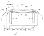
図1に示すように、車両10の前端に車幅方向に延在するバンパーカバー12が配置され、バンパーカバー12の後方に車幅方向に延在するバンパービーム14が配置され、バンパービーム14は、左右一対のサイドフレーム16により支持されている。
車両10は歩行者衝突検出装置18を備え、歩行者衝突検出装置18は、車両前部に対する歩行者の衝突を検出して後述する歩行者保護装置26を機能させるためのものである。
(First embodiment)
Hereinafter, embodiments of the present invention will be described with reference to the drawings.
In FIG. 1 to FIG. 3, symbol FR indicates the front of the vehicle, symbol RR indicates the rear of the vehicle, symbol UP indicates the vehicle upper side, and symbol DOWN indicates the vehicle lower side.
As shown in FIG. 1, a
The
歩行者衝突検出装置18は、緩衝部材20と、圧力チューブ22と、圧力検出器24とを含んで構成されている。
圧力チューブ22は、後述するようにバンパーカバー12とバンパービーム14との間に緩衝部材20を介して配置され、圧力チューブ22の内部には気体が満たされ、圧力チューブ22は車幅方向に延在している。
圧力検出器24は、緩衝部材20の車幅方向両端からそれぞれ突出する圧力チューブ22の端部に設けられている。
圧力検出器24は、圧力チューブ22の圧力(内圧)の変化を検出するものである。
The pedestrian
As will be described later, the
The
The
圧力検出器24には歩行者保護装置26が接続されている。
歩行者保護装置26は、ECU28と、アクチュエータ30と、フード32あるいはエアバッグとを含んで構成されている。
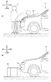
すなわち、ECU28は、圧力検出器24の検出結果に基づいて歩行者が車両前部に衝突したか否かを判定し、歩行者が衝突したと判定した場合にアクチュエータ30を作動して図3(A)に示すように、フード32の後部を持ち上げることで歩行者Hの保護を図る。
あるいは、歩行者保護装置26は、フード32を持ち上げる代わりに、エアバッグを展開させることで歩行者Hの保護を図るものであってもよい。
なお、フード32を持ち上げる、あるいは、エアバッグを展開させる歩行者保護装置26は、不図示のガス発生装置(インフレータ)によって発生したガスによって動作するものであることから1回使用すると、交換する必要がある。
A
The
That is, the ECU 28 determines whether or not the pedestrian has collided with the front portion of the vehicle based on the detection result of the
Alternatively, the
Note that the
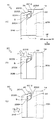
図1、図2(A)に示すように、緩衝部材20は、バンパービーム14とバンパーカバー12との間に配置され、バンパービーム14に沿って車幅方向に延在されている。緩衝部材20は、車両前後方向の厚さTが、車幅方向に亘って均一となるよう形成されている。緩衝部材20は、その背面がバンパービームの前面に接着等の様々な方法により固定されている。
緩衝部材20は、例えば、歩行者Hと衝突したときに歩行者Hの保護を図るような衝撃吸収機能を発揮する発泡合成樹脂材料で形成されており、このような発泡合成樹脂材料として従来公知の様々な弾性材料が使用可能である。
As shown in FIGS. 1 and 2A, the
The
緩衝部材20の上端部の近傍には、車幅方向に延在し圧力チューブ22が収容される収容空間Sが設けられている。
緩衝部材20の収容空間Sの上方に位置する上壁2002を構成する緩衝部材部分は、緩衝部材20の他の部分に比べて薄肉の上壁部2010で形成されている。
上壁部2010は、図2(B)に示すように、緩衝部材20の上部に上方から車両後方斜め下方へ向かって所定以上の衝撃力が作用した際に、収容空間Sの内側へ弾性変形して収容空間Sの下方に位置する底壁2004との間で圧力チューブ22を圧縮するよう構成されている。
上壁部2010は、緩衝部材20の収容空間Sの前方に位置する前壁2006の上端から車両後方に至るにつれて上方に変位する傾斜で後方に延設されている。
また、上壁部2010の後端2012は、緩衝部材20の収容空間Sの後方に位置する後壁2008に対して切り離されて形成され、後壁2008の近傍に位置されている。
収容空間Sの後壁2008の上部には、上壁部2002の後端2012の上方への変位を規制する変位規制部34が設けられている。
本実施の形態では、変形規制部34は、上壁部2010の後端2012より上方の位置で後壁2008から車両前方へ突接され、上壁部2010に上方から係止するよう構成されている。
なお、変位規制部34は、上壁部2010の後端2012が挿入される凹部で構成されるなど任意であり、従来公知の様々な構造が採用可能である。
収容空間Sの底壁2004は、その壁面が車両10の後方から前方に至るにつれ次第に下方に変位する傾斜面とされている。
緩衝部材20の収容空間Sの前壁2006を構成している部分は、上壁部2010に比べて肉厚に形成されている。
An accommodation space S that extends in the vehicle width direction and accommodates the
The buffer member portion constituting the
As shown in FIG. 2 (B), the
The
Further, the
A
In the present embodiment, the
In addition, the
The
A portion constituting the
図2(A)に示すように、緩衝部材20は、バンパービーム14に固定される第1の緩衝部材20Aと、第1の緩衝部材20Aの前方に位置して第1の緩衝部材20Aに接合される第2の緩衝部材20Bとを含んで構成されている。
そして、収容空間Sは、この第1の緩衝部材20Aと第2の緩衝部材の間に形成される。
第1の緩衝部材20Aは、収容空間Sの下方および後方に位置され、収容空間Sの底壁2004を成す部分と後壁2008を成す部分とを構成し、第2の緩衝部材20Bは、収容空間Sの前方および上方に位置され、収容空間Sの前壁2006を成す部分と上壁2002を成す部分(上壁部2010)とを構成している。
また、第2の緩衝部材20Bは、第1の緩衝部材20Aよりも硬度が低い材料で形成されている。
つまり、第2の緩衝部材20Bの硬度を低く設定することで第1の緩衝部材20Aよりも車両前方側の第2の緩衝部材20Bが変形し易い構造としている。
そして、収容空間Sは、上壁部2010(上壁2002)と前壁2006を成す前方および上方側の部位が変形し易く、底壁2004と後壁2008を成す下方および後方側の部位が変形し難くい構成とされる。
第2の緩衝部材20Bのうち収容空間Sの前方に位置する前壁2006の部分と上壁部2010とを除いた残りの箇所は、第1の緩衝部材20Aの前面に接着剤等で接合されている。
As shown in FIG. 2A, the
The accommodation space S is formed between the
The
In addition, the
That is, by setting the hardness of the
In the accommodation space S, the front and upper side portions forming the upper wall 2010 (upper wall 2002) and the
The remaining portions of the
次に本実施の形態における歩行者衝突検出装置18の作用効果について説明する。
図3(A)に示すように、歩行者Hが車両前部に衝突した場合、図2(B)に示すように、歩行者Hの上半身が後方へ倒れ込むため、バンパーカバー12には、上方側から車両後方斜め下方側へ衝撃力F1が入力される。
このため、バンパーカバー12を介してその衝撃力F1が、緩衝部材20(第1の緩衝部材20A)の上部に対して車両後方斜め下方へ向かって作用する。
この衝撃力F1により、前壁2006の部分が下方へ圧縮されつつ上壁部2010が下方側、すなわち収容空間Sの内側へ弾性変形される。
そして、上壁部2010が弾性変形により収容空間S内に進入してくることで圧力チューブ22は上壁部2010と底壁2004との間で圧縮され、圧力検出器24により圧力チューブ22の圧力変化が検出される。
ECU28がその検出結果に基いてアクチュエータ30によりフード32を持ち上げ、あるいは、エアバッグをフード32上に展開させ、歩行者Hの保護が図られる。
なお、本実施の形態では、上壁部2010の後端2012を収容空間Sの後壁2008と切り離すことで、後端2012が連結されている場合に比べて上壁部2010の弾性変形が容易な構成とし、収容空間S内への進入量が大きくなるようにしている。
さらに、底壁2004が車両後方から前方に至るにつれ次第に下方に変位する傾斜面とされており、底壁2004の壁面を衝撃力F1の入力方向に向けることで底壁2004が衝撃力F1をより受け易くなるようにしている。つまり上壁部2010および底壁2004の構造によって圧力チューブ22の圧縮がより確実に行えるよう図られている。
また、上壁部2010は第2の緩衝部材20Bで構成され、第2の緩衝部材20Bは、第1の緩衝部材20Aよりも硬度が低い材料で形成されているので、歩行者Hが車両前部に衝突した際、その衝撃力F1により緩衝部材20の上端かつ前方側に位置する前壁2006の部分および上壁部2010が変形し易く、反応よく圧力チューブ22を圧縮することができるように図られている。
Next, the effect of the pedestrian
As shown in FIG. 3 (A), when the pedestrian H collides with the front of the vehicle, the upper body of the pedestrian H falls backward as shown in FIG. 2 (B). The impact force F1 is input from the side to the vehicle rear obliquely lower side.
For this reason, the impact force F1 acts on the upper part of the buffer member 20 (
Due to the impact force F1, the
The
Based on the detection result, the
In the present embodiment, by separating the
Furthermore, the
Moreover, since the
一方、図3(B)に示すように、路上構造物Mが車両前部に衝突した場合、図2(C)に示すように、バンパーカバー12には、主に下方側から車両後方斜め上方側へ作用する衝撃力F2が入力される。
このため、バンパーカバー12を介してその衝撃力F2が、緩衝部材20(第2の緩衝部材20B)に対して車両後方斜め上方へ作用する。
この衝撃力F2により、緩衝部材20の収容空間Sより前方側に位置する第2の緩衝部材20Bの下部側は、前後方向に大きく変形するが、衝撃力F2は、主に緩衝部材20の下方側に入力されるため、上壁部2010への影響が少なく弾性変形が抑制される。
また、収容空間Sの下方および後方側を第1の緩衝部材20Aで構成し、収容空間Sは底壁2004および後壁2008が変形し難い構造とされているので、衝撃力F2に対して収容空間Sの変形が抑制され、圧力チューブ22の圧縮が抑制される。
そのため、圧力検出器24により圧力チューブ22の圧力変化が検出されることはなく、フード32の持ち上げやエアバッグの展開は禁止される。
なお、本実施の形態では、上壁部2010は、変位規制部34によって上方への変位が規制されるので、上壁部2010の後端2012が後壁2008から上方へ外れて収容空間Sが大きく変形され、容積が縮小されることを抑制している。
したがって、本実施の形態の歩行者衝突検出装置18によれば、歩行者Hが車両前部に衝突した場合には、圧力チューブ22が圧縮されやすく、路上構造物Mなどが車両前部に衝突した場合には、圧力チューブ22が圧縮されにくくなるので、歩行者との衝突判定をより正確に行うことができ、歩行者衝突の検出精度を向上させることができる。ゆえに誤判定を抑制して歩行者保護装置26の不要な作動を低減させることができる。
On the other hand, as shown in FIG. 3B, when the road structure M collides with the front of the vehicle, as shown in FIG. The impact force F2 acting on the side is input.
For this reason, the impact force F2 acts on the shock absorbing member 20 (second
Due to the impact force F2, the lower side of the
Further, the lower side and the rear side of the accommodation space S are configured by the
Therefore, the pressure change of the
In the present embodiment, the
Therefore, according to the pedestrian
(第2の実施の形態)
次に第2の実施の形態について図4を参照して説明する。
なお、以下の実施の形態では、第1の実施の形態と同様な箇所、部材に同一の符号を付してその説明を省略し、異なった箇所を重点的に説明する。
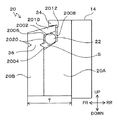
第2の実施の形態では、前壁2006に、上壁部2010の収容空間S内側への弾性変形を誘発する変形誘発部36が設けられている。
第2の実施の形態では、前壁2006を構成する部位の下部近傍、すなわち底壁2004と交差する部分の近傍の部位の前面と後面にそれぞれ車幅方向に延在する凹溝2020が設けられ、変形誘発部36は、それら凹溝2020の間に位置する薄肉部で形成されている。
この変形誘発部36により、歩行者Hが車両前部に衝突した際、その衝撃力により前壁2006が収容空間S側へ弾性変形、すなわち前壁2006が車両後方側へ倒れ易い構造とされている。これにより、上壁部2010の収容空間S内側への弾性変形を誘発するとともに促進し、圧力チューブ22がより確実に圧縮されように図られている。
なお、変形誘発部36は、前壁2006の下部の部分を、第2の緩衝部材20Bよりも柔らかい材料で形成することで構成するなど任意であり、従来公知の様々な構造が採用可能である。
以上本発明の歩行者衝突検知装置について説明したが、上述した実施形態における各構成およびそれの組合せ等は一例であり、本発明の趣旨から逸脱しない範囲内で変更が可能であることはいうまでもない。
(Second Embodiment)
Next, a second embodiment will be described with reference to FIG.
In the following embodiments, the same portions and members as those in the first embodiment are denoted by the same reference numerals, the description thereof is omitted, and different portions are mainly described.
In the second embodiment, the
In the second embodiment,
When the pedestrian H collides with the front part of the vehicle, the
The
Although the pedestrian collision detection device of the present invention has been described above, each configuration in the above-described embodiment and combinations thereof are examples, and it is needless to say that changes can be made without departing from the spirit of the present invention. Nor.
10 車両
12 バンパーカバー
14 バンパービーム
18 歩行者衝突検出装置
20 緩衝部材
2002 上壁
2004 底壁
2006 前壁
2008 後壁
2010 上壁部
2012 後端
22 圧力チューブ
24 圧力検出器
34 変位規制部
36 変形誘発部
S 収容空間
DESCRIPTION OF
Claims (6)
前記緩衝材を介して前記バンパービームと前記バンパーカバーとの間に配置された車幅方向に延在する圧力チューブと、
前記圧力チューブの圧力変化に応じた信号を出力する圧力検出器と、
を備える車両の歩行者衝突検出装置であって、
前記緩衝部材の上端部近傍に、車幅方向に延在し前記圧力チューブが収容される収容空間が設けられ、
前記緩衝部材の前記収容空間の上方に位置して上壁となる部分に、前記緩衝部材上方側から車両後方斜め下方へ向かって衝撃力が作用した際に、前記収容空間内に弾性変形して前記圧力チューブを圧縮する上壁部が形成されている、
ことを特徴とする車両の歩行者衝突検出装置。 Cushioning material disposed between the bumper beam and the bumper cover;
A pressure tube that extends between the bumper beam and the bumper cover and extends in the vehicle width direction via the cushioning material;
A pressure detector that outputs a signal corresponding to a pressure change in the pressure tube;
A vehicle pedestrian collision detection device comprising:
An accommodating space that extends in the vehicle width direction and accommodates the pressure tube is provided in the vicinity of the upper end of the buffer member,
When an impact force acts on the portion of the cushioning member located above the accommodation space and serving as the upper wall from the upper side of the cushioning member toward the obliquely lower rear of the vehicle, it is elastically deformed in the accommodation space. An upper wall for compressing the pressure tube is formed;
A pedestrian collision detection apparatus for vehicles.
前記第1の緩衝部材が前記収容空間の下方および後方に位置して前記収容空間の底壁を成す部分と後壁を成す部分を構成し、前記第2の緩衝部材が前記収容空間の前方および上方に位置して前記収容空間の前壁を成す部分と前記上壁を成す上壁部を構成する、
ことを特徴とする請求項1記載の車両の歩行者衝突検出装置。 The buffer member is a first buffer member supported by the bumper beam and a second buffer member joined to the front of the first buffer member and having a lower hardness than the first buffer member. And comprising
The first buffer member is positioned below and behind the housing space to form a bottom wall portion and a rear wall portion, and the second buffer member is located in front of the housing space and A portion that forms a front wall of the housing space and an upper wall portion that forms the upper wall are located above,
The vehicle pedestrian collision detection apparatus according to claim 1.
前記上壁部の後端は、前記収容空間の前記後壁に対して切り離された状態で同後壁の近傍に位置される、
ことを特徴とする請求項1又は2記載の車両の歩行者衝突検出装置。 The upper wall portion extends from the upper end of the front wall of the housing space to the rear of the vehicle,
The rear end of the upper wall portion is positioned in the vicinity of the rear wall in a state of being separated from the rear wall of the accommodation space.
The pedestrian collision detection device for a vehicle according to claim 1 or 2.
ことを特徴とする請求項3記載の車両の歩行者衝突検出装置。 The rear wall of the accommodating space is provided with a displacement restricting portion that is located above the rear end of the upper wall portion and restricts the upward displacement of the upper wall portion.
The pedestrian collision detection device for a vehicle according to claim 3.
ことを特徴とする請求項1から4の何れか1項に記載の車両の歩行者衝突検出装置。 The bottom wall of the housing space is an inclined surface that gradually displaces downward from the rear to the front of the vehicle.
The pedestrian collision detection device for a vehicle according to any one of claims 1 to 4, wherein the pedestrian collision detection device is a vehicle.
ことを特徴とする請求項1から5の何れか1項に記載の車両の歩行者衝突検出装置。 A portion that forms the front wall of the buffer member is provided with a deformation inducing portion that induces elastic deformation of the upper wall portion toward the inside of the accommodating space.
The pedestrian collision detection device for a vehicle according to any one of claims 1 to 5, wherein
Priority Applications (1)
| Application Number | Priority Date | Filing Date | Title |
|---|---|---|---|
| JP2015237282A JP2017100643A (en) | 2015-12-04 | 2015-12-04 | Vehicular pedestrian collision detection apparatus |
Applications Claiming Priority (1)
| Application Number | Priority Date | Filing Date | Title |
|---|---|---|---|
| JP2015237282A JP2017100643A (en) | 2015-12-04 | 2015-12-04 | Vehicular pedestrian collision detection apparatus |
Publications (1)
| Publication Number | Publication Date |
|---|---|
| JP2017100643A true JP2017100643A (en) | 2017-06-08 |
Family
ID=59015965
Family Applications (1)
| Application Number | Title | Priority Date | Filing Date |
|---|---|---|---|
| JP2015237282A Pending JP2017100643A (en) | 2015-12-04 | 2015-12-04 | Vehicular pedestrian collision detection apparatus |
Country Status (1)
| Country | Link |
|---|---|
| JP (1) | JP2017100643A (en) |
Cited By (5)
| Publication number | Priority date | Publication date | Assignee | Title |
|---|---|---|---|---|
| WO2019039133A1 (en) * | 2017-08-21 | 2019-02-28 | トヨタ車体株式会社 | Vehicle bumper |
| CN110997417A (en) * | 2017-10-24 | 2020-04-10 | 本田技研工业株式会社 | Collision detection structure |
| CN111194282A (en) * | 2017-10-24 | 2020-05-22 | 本田技研工业株式会社 | Collision detection structure |
| CN111201162A (en) * | 2017-10-24 | 2020-05-26 | 本田技研工业株式会社 | Collision detection structure |
| JP7424865B2 (en) | 2020-03-02 | 2024-01-30 | 株式会社Subaru | Collision detection device |
-
2015
- 2015-12-04 JP JP2015237282A patent/JP2017100643A/en active Pending
Cited By (10)
| Publication number | Priority date | Publication date | Assignee | Title |
|---|---|---|---|---|
| WO2019039133A1 (en) * | 2017-08-21 | 2019-02-28 | トヨタ車体株式会社 | Vehicle bumper |
| JP2019034680A (en) * | 2017-08-21 | 2019-03-07 | トヨタ車体株式会社 | Vehicular bumper |
| CN110891828A (en) * | 2017-08-21 | 2020-03-17 | 丰田车体株式会社 | Bumper for vehicle |
| US11052846B2 (en) | 2017-08-21 | 2021-07-06 | Toyota Shatai Kabushiki Kaisha | Vehicle bumper |
| CN110891828B (en) * | 2017-08-21 | 2022-09-27 | 丰田车体株式会社 | Bumper for vehicle |
| CN110997417A (en) * | 2017-10-24 | 2020-04-10 | 本田技研工业株式会社 | Collision detection structure |
| CN111194282A (en) * | 2017-10-24 | 2020-05-22 | 本田技研工业株式会社 | Collision detection structure |
| CN111201162A (en) * | 2017-10-24 | 2020-05-26 | 本田技研工业株式会社 | Collision detection structure |
| US11267417B2 (en) | 2017-10-24 | 2022-03-08 | Honda Motor Co. Ltd. | Collision detecting structure |
| JP7424865B2 (en) | 2020-03-02 | 2024-01-30 | 株式会社Subaru | Collision detection device |
Similar Documents
| Publication | Publication Date | Title |
|---|---|---|
| JP5302643B2 (en) | Collision detection device and collision detection method | |
| JP2017100643A (en) | Vehicular pedestrian collision detection apparatus | |
| US10358106B2 (en) | Airbag apparatus | |
| US8653958B2 (en) | Collision detection apparatus and method for same | |
| JP6285977B2 (en) | Bumper for vehicle | |
| US9902363B2 (en) | Airbag device | |
| JP2009018741A (en) | Vehicle collision detector | |
| JP2009137435A (en) | Vehicle body front part structure | |
| JP2017007368A (en) | Vehicle bumper structure including pedestrian collision detection sensor | |
| JP4434293B2 (en) | Vehicle collision detection device | |
| CN103492244A (en) | Method to achieve early/robust g-signal for side pole | |
| JP5499907B2 (en) | Pedestrian collision detection device | |
| KR101250413B1 (en) | Unification air-bag module | |
| JP2008239121A (en) | Vehicle side collision detection device | |
| JP4858786B2 (en) | Vehicle collision detection device | |
| JP7431060B2 (en) | Collision detection device | |
| JP2015157512A (en) | pedestrian collision detection system | |
| JP2017100563A (en) | Vehicular pedestrian collision detection apparatus | |
| JP2015077826A (en) | Vehicle collision determination device | |
| JP6627460B2 (en) | Vehicle pedestrian collision detection device | |
| CN109204198B (en) | System for deploying an airbag in a vehicle | |
| JP6334337B2 (en) | Vehicle collision detection sensor mounting structure | |
| JP2017087848A (en) | Air bag device | |
| JP6408312B2 (en) | Pedestrian collision detection device | |
| JP5994666B2 (en) | Bumper for vehicle equipped with pedestrian collision detection device |
Legal Events
| Date | Code | Title | Description |
|---|---|---|---|
| A621 | Written request for application examination |
Free format text: JAPANESE INTERMEDIATE CODE: A621 Effective date: 20181130 |
|
| A977 | Report on retrieval |
Free format text: JAPANESE INTERMEDIATE CODE: A971007 Effective date: 20190913 |
|
| A131 | Notification of reasons for refusal |
Free format text: JAPANESE INTERMEDIATE CODE: A131 Effective date: 20190924 |
|
| A02 | Decision of refusal |
Free format text: JAPANESE INTERMEDIATE CODE: A02 Effective date: 20200519 |