JP2017014008A - Conveyance unit and printer - Google Patents
Conveyance unit and printer Download PDFInfo
- Publication number
- JP2017014008A JP2017014008A JP2015135687A JP2015135687A JP2017014008A JP 2017014008 A JP2017014008 A JP 2017014008A JP 2015135687 A JP2015135687 A JP 2015135687A JP 2015135687 A JP2015135687 A JP 2015135687A JP 2017014008 A JP2017014008 A JP 2017014008A
- Authority
- JP
- Japan
- Prior art keywords
- unit
- recording medium
- recording
- printer
- print unit
- Prior art date
- Legal status (The legal status is an assumption and is not a legal conclusion. Google has not performed a legal analysis and makes no representation as to the accuracy of the status listed.)
- Granted
Links
- 238000009826 distribution Methods 0.000 claims abstract description 29
- 230000032258 transport Effects 0.000 claims description 184
- 238000005520 cutting process Methods 0.000 claims description 45
- 238000007639 printing Methods 0.000 claims description 22
- 238000007599 discharging Methods 0.000 claims description 3
- 238000013461 design Methods 0.000 abstract description 22
- 238000011161 development Methods 0.000 abstract description 22
- 238000004519 manufacturing process Methods 0.000 abstract description 19
- 230000007246 mechanism Effects 0.000 description 57
- 239000010410 layer Substances 0.000 description 53
- 238000003780 insertion Methods 0.000 description 36
- 230000037431 insertion Effects 0.000 description 36
- 238000001514 detection method Methods 0.000 description 30
- 238000000859 sublimation Methods 0.000 description 22
- 230000008022 sublimation Effects 0.000 description 21
- 238000010586 diagram Methods 0.000 description 15
- 239000003086 colorant Substances 0.000 description 10
- 238000004891 communication Methods 0.000 description 10
- 230000002093 peripheral effect Effects 0.000 description 10
- 238000010438 heat treatment Methods 0.000 description 9
- 239000000758 substrate Substances 0.000 description 8
- 238000007796 conventional method Methods 0.000 description 6
- 239000011888 foil Substances 0.000 description 6
- 238000012545 processing Methods 0.000 description 6
- 238000012546 transfer Methods 0.000 description 6
- 238000004804 winding Methods 0.000 description 6
- 239000000463 material Substances 0.000 description 5
- 230000005540 biological transmission Effects 0.000 description 4
- 238000000034 method Methods 0.000 description 4
- 230000003287 optical effect Effects 0.000 description 4
- 238000005452 bending Methods 0.000 description 3
- 230000008859 change Effects 0.000 description 3
- 230000006870 function Effects 0.000 description 2
- PCHJSUWPFVWCPO-UHFFFAOYSA-N gold Chemical compound [Au] PCHJSUWPFVWCPO-UHFFFAOYSA-N 0.000 description 2
- 229910052737 gold Inorganic materials 0.000 description 2
- 239000010931 gold Substances 0.000 description 2
- 229910052709 silver Inorganic materials 0.000 description 2
- 239000004332 silver Substances 0.000 description 2
- XLYOFNOQVPJJNP-UHFFFAOYSA-N water Substances O XLYOFNOQVPJJNP-UHFFFAOYSA-N 0.000 description 2
- 230000006866 deterioration Effects 0.000 description 1
- 238000009792 diffusion process Methods 0.000 description 1
- 230000000694 effects Effects 0.000 description 1
- 238000005516 engineering process Methods 0.000 description 1
- 238000010030 laminating Methods 0.000 description 1
- 238000012423 maintenance Methods 0.000 description 1
- 238000003825 pressing Methods 0.000 description 1
- 230000008569 process Effects 0.000 description 1
- 239000011241 protective layer Substances 0.000 description 1
- 238000003860 storage Methods 0.000 description 1
- 239000002699 waste material Substances 0.000 description 1
Images


Classifications
-
- B—PERFORMING OPERATIONS; TRANSPORTING
- B41—PRINTING; LINING MACHINES; TYPEWRITERS; STAMPS
- B41J—TYPEWRITERS; SELECTIVE PRINTING MECHANISMS, i.e. MECHANISMS PRINTING OTHERWISE THAN FROM A FORME; CORRECTION OF TYPOGRAPHICAL ERRORS
- B41J3/00—Typewriters or selective printing or marking mechanisms characterised by the purpose for which they are constructed
- B41J3/60—Typewriters or selective printing or marking mechanisms characterised by the purpose for which they are constructed for printing on both faces of the printing material
-
- B—PERFORMING OPERATIONS; TRANSPORTING
- B41—PRINTING; LINING MACHINES; TYPEWRITERS; STAMPS
- B41J—TYPEWRITERS; SELECTIVE PRINTING MECHANISMS, i.e. MECHANISMS PRINTING OTHERWISE THAN FROM A FORME; CORRECTION OF TYPOGRAPHICAL ERRORS
- B41J11/00—Devices or arrangements of selective printing mechanisms, e.g. ink-jet printers or thermal printers, for supporting or handling copy material in sheet or web form
- B41J11/66—Applications of cutting devices
- B41J11/70—Applications of cutting devices cutting perpendicular to the direction of paper feed
-
- B—PERFORMING OPERATIONS; TRANSPORTING
- B41—PRINTING; LINING MACHINES; TYPEWRITERS; STAMPS
- B41J—TYPEWRITERS; SELECTIVE PRINTING MECHANISMS, i.e. MECHANISMS PRINTING OTHERWISE THAN FROM A FORME; CORRECTION OF TYPOGRAPHICAL ERRORS
- B41J13/00—Devices or arrangements of selective printing mechanisms, e.g. ink-jet printers or thermal printers, specially adapted for supporting or handling copy material in short lengths, e.g. sheets
- B41J13/0009—Devices or arrangements of selective printing mechanisms, e.g. ink-jet printers or thermal printers, specially adapted for supporting or handling copy material in short lengths, e.g. sheets control of the transport of the copy material
- B41J13/0045—Devices or arrangements of selective printing mechanisms, e.g. ink-jet printers or thermal printers, specially adapted for supporting or handling copy material in short lengths, e.g. sheets control of the transport of the copy material concerning sheet refeed sections of automatic paper handling systems, e.g. intermediate stackers
-
- B—PERFORMING OPERATIONS; TRANSPORTING
- B41—PRINTING; LINING MACHINES; TYPEWRITERS; STAMPS
- B41J—TYPEWRITERS; SELECTIVE PRINTING MECHANISMS, i.e. MECHANISMS PRINTING OTHERWISE THAN FROM A FORME; CORRECTION OF TYPOGRAPHICAL ERRORS
- B41J15/00—Devices or arrangements of selective printing mechanisms, e.g. ink-jet printers or thermal printers, specially adapted for supporting or handling copy material in continuous form, e.g. webs
- B41J15/04—Supporting, feeding, or guiding devices; Mountings for web rolls or spindles
-
- B—PERFORMING OPERATIONS; TRANSPORTING
- B41—PRINTING; LINING MACHINES; TYPEWRITERS; STAMPS
- B41J—TYPEWRITERS; SELECTIVE PRINTING MECHANISMS, i.e. MECHANISMS PRINTING OTHERWISE THAN FROM A FORME; CORRECTION OF TYPOGRAPHICAL ERRORS
- B41J15/00—Devices or arrangements of selective printing mechanisms, e.g. ink-jet printers or thermal printers, specially adapted for supporting or handling copy material in continuous form, e.g. webs
- B41J15/18—Multiple web-feeding apparatus
-
- B—PERFORMING OPERATIONS; TRANSPORTING
- B41—PRINTING; LINING MACHINES; TYPEWRITERS; STAMPS
- B41J—TYPEWRITERS; SELECTIVE PRINTING MECHANISMS, i.e. MECHANISMS PRINTING OTHERWISE THAN FROM A FORME; CORRECTION OF TYPOGRAPHICAL ERRORS
- B41J2/00—Typewriters or selective printing mechanisms characterised by the printing or marking process for which they are designed
- B41J2/315—Typewriters or selective printing mechanisms characterised by the printing or marking process for which they are designed characterised by selective application of heat to a heat sensitive printing or impression-transfer material
- B41J2/32—Typewriters or selective printing mechanisms characterised by the printing or marking process for which they are designed characterised by selective application of heat to a heat sensitive printing or impression-transfer material using thermal heads
- B41J2/325—Typewriters or selective printing mechanisms characterised by the printing or marking process for which they are designed characterised by selective application of heat to a heat sensitive printing or impression-transfer material using thermal heads by selective transfer of ink from ink carrier, e.g. from ink ribbon or sheet
-
- B—PERFORMING OPERATIONS; TRANSPORTING
- B41—PRINTING; LINING MACHINES; TYPEWRITERS; STAMPS
- B41J—TYPEWRITERS; SELECTIVE PRINTING MECHANISMS, i.e. MECHANISMS PRINTING OTHERWISE THAN FROM A FORME; CORRECTION OF TYPOGRAPHICAL ERRORS
- B41J29/00—Details of, or accessories for, typewriters or selective printing mechanisms not otherwise provided for
-
- B—PERFORMING OPERATIONS; TRANSPORTING
- B41—PRINTING; LINING MACHINES; TYPEWRITERS; STAMPS
- B41J—TYPEWRITERS; SELECTIVE PRINTING MECHANISMS, i.e. MECHANISMS PRINTING OTHERWISE THAN FROM A FORME; CORRECTION OF TYPOGRAPHICAL ERRORS
- B41J3/00—Typewriters or selective printing or marking mechanisms characterised by the purpose for which they are constructed
- B41J3/54—Typewriters or selective printing or marking mechanisms characterised by the purpose for which they are constructed with two or more sets of type or printing elements
-
- B—PERFORMING OPERATIONS; TRANSPORTING
- B65—CONVEYING; PACKING; STORING; HANDLING THIN OR FILAMENTARY MATERIAL
- B65H—HANDLING THIN OR FILAMENTARY MATERIAL, e.g. SHEETS, WEBS, CABLES
- B65H29/00—Delivering or advancing articles from machines; Advancing articles to or into piles
- B65H29/58—Article switches or diverters
- B65H29/60—Article switches or diverters diverting the stream into alternative paths
-
- B—PERFORMING OPERATIONS; TRANSPORTING
- B65—CONVEYING; PACKING; STORING; HANDLING THIN OR FILAMENTARY MATERIAL
- B65H—HANDLING THIN OR FILAMENTARY MATERIAL, e.g. SHEETS, WEBS, CABLES
- B65H35/00—Delivering articles from cutting or line-perforating machines; Article or web delivery apparatus incorporating cutting or line-perforating devices, e.g. adhesive tape dispensers
- B65H35/0006—Article or web delivery apparatus incorporating cutting or line-perforating devices
- B65H35/006—Article or web delivery apparatus incorporating cutting or line-perforating devices with means for delivering a predetermined length of tape
-
- B—PERFORMING OPERATIONS; TRANSPORTING
- B65—CONVEYING; PACKING; STORING; HANDLING THIN OR FILAMENTARY MATERIAL
- B65H—HANDLING THIN OR FILAMENTARY MATERIAL, e.g. SHEETS, WEBS, CABLES
- B65H2301/00—Handling processes for sheets or webs
- B65H2301/10—Selective handling processes
- B65H2301/13—Relative to size or orientation of the material
- B65H2301/132—Relative to size or orientation of the material single face or double face
-
- B—PERFORMING OPERATIONS; TRANSPORTING
- B65—CONVEYING; PACKING; STORING; HANDLING THIN OR FILAMENTARY MATERIAL
- B65H—HANDLING THIN OR FILAMENTARY MATERIAL, e.g. SHEETS, WEBS, CABLES
- B65H2301/00—Handling processes for sheets or webs
- B65H2301/30—Orientation, displacement, position of the handled material
- B65H2301/33—Modifying, selecting, changing orientation
- B65H2301/333—Inverting
- B65H2301/3331—Involving forward reverse transporting means
- B65H2301/33312—Involving forward reverse transporting means forward reverse rollers pairs
-
- B—PERFORMING OPERATIONS; TRANSPORTING
- B65—CONVEYING; PACKING; STORING; HANDLING THIN OR FILAMENTARY MATERIAL
- B65H—HANDLING THIN OR FILAMENTARY MATERIAL, e.g. SHEETS, WEBS, CABLES
- B65H2404/00—Parts for transporting or guiding the handled material
- B65H2404/60—Other elements in face contact with handled material
- B65H2404/63—Oscillating, pivoting around an axis parallel to face of material, e.g. diverting means
- B65H2404/632—Wedge member
-
- B—PERFORMING OPERATIONS; TRANSPORTING
- B65—CONVEYING; PACKING; STORING; HANDLING THIN OR FILAMENTARY MATERIAL
- B65H—HANDLING THIN OR FILAMENTARY MATERIAL, e.g. SHEETS, WEBS, CABLES
- B65H2801/00—Application field
- B65H2801/03—Image reproduction devices
- B65H2801/12—Single-function printing machines, typically table-top machines
Abstract
Description
この発明は、記録媒体の両面への記録が可能なプリンタおよび当該プリンタに用いられる搬送ユニットに関する。 The present invention relates to a printer capable of recording on both sides of a recording medium and a transport unit used in the printer.
従来、外部装置から受け付けた記録指示に基づいて、記録対象とする記録媒体に対する記録動作をおこなうプリンタがあった。このようなプリンタには、記録媒体の片面のみならず、記録媒体の両面に対する記録動作をおこなうものがあった。このようなプリンタにおいては、巻回された状態の記録媒体を所定の長さで切断して使用するものがあった。 Conventionally, there has been a printer that performs a recording operation on a recording medium to be recorded based on a recording instruction received from an external device. Some printers perform a recording operation not only on one side of the recording medium but also on both sides of the recording medium. In such a printer, there is a printer in which a wound recording medium is cut at a predetermined length.
具体的には、従来、たとえば、記録媒体に対する記録動作をおこなうサーマルプリンタにおいて、巻回された状態の記録媒体を保持する保持部または記録媒体に対する記録動作をおこなうサーマルヘッド部を回転させる反転機構を備え、当該反転機構によりサーマルヘッド部に臨む記録媒体の表裏を反転させることによって、記録媒体の両面に対して記録動作をおこなうようにした技術があった(たとえば、下記特許文献1を参照。)。 Specifically, for example, in a conventional thermal printer that performs a recording operation on a recording medium, a reversing mechanism that rotates a holding unit that holds the wound recording medium or a thermal head unit that performs the recording operation on the recording medium is provided. There is a technique in which a recording operation is performed on both sides of the recording medium by reversing the front and back of the recording medium facing the thermal head portion by the reversing mechanism (see, for example, Patent Document 1 below). .
また、具体的には、従来、たとえば、インクリボンなどの通常の消耗品を用いた通常の記録動作をおこなうサーマルヘッド部、および、記録媒体の表面を保護する保護層を設けたり金・銀・色箔を設ける加工(箔押し)をおこなったりするための特殊な記録動作をおこなうサーマルヘッド部、のように複数のサーマルヘッド部を備えたサーマルプリンタにおいて、巻回された状態の記録媒体を保持する保持部または記録媒体に対する記録動作をおこなうサーマルヘッド部を回転させる反転機構を備え、当該反転機構によりサーマルヘッド部に臨む記録媒体の表裏を反転させることによって、記録媒体の両面に対して記録動作をおこなうようにした技術があった(たとえば、下記特許文献2を参照。)。 Specifically, conventionally, for example, a thermal head unit that performs a normal recording operation using a normal consumable such as an ink ribbon, and a protective layer that protects the surface of the recording medium are provided. In a thermal printer having a plurality of thermal heads, such as a thermal head that performs a special recording operation for performing processing (foil pressing) for providing colored foil, the recording medium in a wound state is held. A reversing mechanism that rotates a thermal head unit that performs a recording operation on the holding unit or the recording medium is provided. There has been a technique to perform (see, for example, Patent Document 2 below).
また、具体的には、従来、たとえば、記録媒体に対して記録動作をおこなうプリンタユニットと反転ユニットとを備えたプリンタにおいて、反転ユニットに単票紙状の記録媒体を保持し、プリンタユニットが長尺状の記録媒体に対して記録動作をおこなうとともに、単票状の記録媒体に対して記録動作をおこなうようにした技術があった(たとえば、下記特許文献3を参照。)。 Specifically, conventionally, for example, in a printer including a printer unit that performs a recording operation on a recording medium and a reversing unit, the reversing unit holds a sheet-like recording medium, and the printer unit is long. There has been a technique in which a recording operation is performed on a scale-shaped recording medium and a recording operation is performed on a single-sheet recording medium (see, for example, Patent Document 3 below).
しかしながら、上述した特許文献1および2に記載された従来の技術は、巻回された状態の記録媒体を保持する保持部ごと反転させる機構であるため、装置が大型化するという問題があった。また、上述した特許文献1および2に記載された従来の技術は、保持部とサーマルヘッド部との間に、当該保持部の反転に連動する部材の移動スペースを確保しなくてはならないため、装置が大型化するという問題があった。 However, since the conventional techniques described in Patent Documents 1 and 2 described above are mechanisms for reversing the entire holding unit that holds the wound recording medium, there is a problem that the apparatus is increased in size. In addition, since the conventional techniques described in Patent Documents 1 and 2 described above must secure a moving space for a member that interlocks with the reversal of the holding unit between the holding unit and the thermal head unit, There was a problem that the apparatus was enlarged.
しかしながら、上述した特許文献1ないし3に記載された従来の技術は、記録媒体の両面に対して記録動作をおこなう場合、片面に記録動作をおこなった記録媒体の表裏を反転ユニットにおいて反転し、おもて面に記録動作をおこなった記録部と同じ記録部を用いて、当該記録媒体の裏面に記録動作をおこなうため、記録媒体の両面に対して記録動作が完了するまでに時間がかかるという問題があった。 However, the conventional techniques described in Patent Documents 1 to 3 described above, when performing the recording operation on both sides of the recording medium, invert the front and back of the recording medium that has performed the recording operation on one side in the reversing unit. Since the recording operation is performed on the back surface of the recording medium using the same recording unit that performed the recording operation on the front surface, it takes time to complete the recording operation on both sides of the recording medium. was there.
また、上述した特許文献1ないし3に記載された従来の技術は、記録媒体の両面に対して記録動作をおこなうため、反転ユニットなどの両面記録に特化した構造が必要になり、開発設計や製造にコストがかかるという問題があった。また、上述した特許文献1に記載された従来の技術は、記録動作をおこなう記録部と、当該記録媒体の表裏を反転させる反転ユニットとを連動して制御するため、専用の制御をおこなわなくてはならず、開発設計にコストがかかるという問題があった。 In addition, since the conventional techniques described in Patent Documents 1 to 3 described above perform the recording operation on both sides of the recording medium, a structure specialized for double-sided recording such as a reversing unit is required. There was a problem that manufacturing was expensive. In addition, the conventional technique described in Patent Document 1 described above controls the recording unit that performs the recording operation and the reversing unit that inverts the front and back of the recording medium in an interlocked manner, and thus does not perform dedicated control. In other words, there was a problem that the development design cost was high.
さらに、上述した特許文献1ないし3に記載された従来の技術は、反転ユニットが、記録動作をおこなう記録部の下方に設けられているため、記録媒体が詰まるいわゆるジャムが発生した場合に、当該ジャムを発生させた記録媒体を取り除くなどの復旧作業が煩雑であるという問題があった。 Furthermore, the conventional techniques described in Patent Documents 1 to 3 described above have the reversing unit provided below the recording unit that performs the recording operation. Therefore, when a so-called jam occurs in which the recording medium is jammed, There has been a problem that the restoration work such as removing the recording medium causing the jam is complicated.
この発明は、上述した従来技術による問題点を解消するため、開発設計や製造にコストをかけることなく、利用者ごとの用途に応じた記録動作をおこなうことができる自由度の高いプリンタおよび当該プリンタに用いられる搬送ユニットを提供することを目的とする。 In order to solve the above-described problems caused by the conventional technology, the present invention provides a printer having a high degree of freedom and capable of performing a recording operation according to the use for each user without incurring development design and manufacturing costs. An object of the present invention is to provide a transport unit used in the above.
上述した課題を解決し、目的を達成するため、この発明にかかる搬送ユニットは、巻回された長尺状の記録媒体を保持する保持部と当該保持部から引き出した記録媒体に対する記録動作をおこなう記録部とを備え、記録動作がおこなわれた長尺状の記録媒体を切断して排出するプリンタに設けられる搬送ユニットであって、前記プリンタから排出される記録媒体を、前記プリンタに重ねられた当該プリンタと同一の構成をなす別のプリンタ側または当該別のプリンタ側とは異なる位置に振り分ける振り分け部と、前記振り分け部によって前記別のプリンタ側に振り分けられた記録媒体が、当該別のプリンタが保持する別の記録媒体を引き出す位置に、当該別の記録媒体の引き出し方向と同一方向に沿って供給されるように案内する案内部と、前記振り分け部によって前記別のプリンタ側とは異なる位置に振り分けられた記録媒体を、当該記録媒体の後端が前記振り分け部を通過するまで収容し、当該後端が前記振り分け部を通過すると、当該記録媒体を当該後端から前記案内部へ搬送する搬送部と、を備え、前記振り分け部が、前記搬送部によって搬送される記録媒体を前記別のプリンタ側に振り分けることを特徴とする。 In order to solve the above-described problems and achieve the object, a transport unit according to the present invention performs a recording operation on a holding unit that holds a wound long recording medium and a recording medium that is drawn from the holding unit. And a recording unit that is provided in a printer that cuts and discharges a long recording medium on which a recording operation has been performed, and the recording medium discharged from the printer is superimposed on the printer Another printer side having the same configuration as the printer or a sorting unit that sorts the printer to a different position from the other printer side, and a recording medium sorted by the sorting unit to the other printer side are A guide unit that guides a position to pull out another recording medium to be held so that the recording medium is supplied along the same direction as the other recording medium; The recording medium distributed by the recording distribution unit to a position different from the other printer side is accommodated until the rear end of the recording medium passes through the distribution unit, and when the rear end passes through the distribution unit, A transport unit that transports the recording medium from the rear end to the guide unit, and the distribution unit distributes the recording medium transported by the transport unit to the other printer side.
また、この発明にかかる搬送ユニットは、上記の発明において、前記振り分け部が、前記プリンタからの前記記録媒体の排出位置の近傍に設けられ、当該排出位置と前記案内部とを連通する第1の位置と、前記搬送部と前記案内部とを連通する第2の位置と、に切替自在なフラップ状部材であることを特徴とする。 In the transport unit according to the present invention, in the above invention, the sorting unit is provided in the vicinity of a discharge position of the recording medium from the printer, and communicates the discharge position with the guide unit. It is a flap-shaped member that is switchable between a position and a second position that communicates the transport section and the guide section.
また、この発明にかかる搬送ユニットは、上記の発明において、前記搬送部が、前記プリンタにおける前記別のプリンタ側とは異なる位置に設けられて、前記別のプリンタ側とは異なる位置に振り分けられた記録媒体を折り曲げることなく収容する空間を備えたことを特徴とする。 In the transport unit according to the present invention, in the above invention, the transport unit is provided at a position different from the other printer side in the printer, and is distributed to a position different from the other printer side. It is characterized by having a space for accommodating the recording medium without bending.
また、この発明にかかる搬送ユニットは、上記の発明において、前記搬送部が、前記別のプリンタ側とは異なる位置に振り分けられた記録媒体を前記空間内に搬送するローラ対を備え、当該ローラ対を第1の回転方向に回転することにより当該記録媒体を当該空間内に収容し、当該第1の回転方向とは逆方向の第2の回転方向に回転することにより当該記録媒体を前記後端から前記案内部へ搬送することを特徴とする。 In the transport unit according to the present invention, in the above invention, the transport unit includes a roller pair that transports the recording medium distributed to a position different from the other printer side into the space. The recording medium is accommodated in the space by rotating the recording medium in the first rotation direction, and the recording medium is rotated in the second rotation direction opposite to the first rotation direction. It conveys to the said guidance part.
また、この発明にかかる搬送ユニットは、上記の発明において、前記空間が、前記プリンタに対し、当該プリンタと前記別のプリンタとが重なる位置とは反対側に設けられていることを特徴とする。 In the transport unit according to the present invention as set forth in the invention described above, the space is provided on the opposite side of the printer from the position where the printer and the other printer overlap.
また、この発明にかかる搬送ユニットは、上記の発明において、前記振り分け部が、前記プリンタから排出される記録媒体を鉛直方向上側または下側に振り分け、前記搬送部に搬送された前記記録媒体を鉛直方向に沿って前記案内部に搬送することを特徴とする。 In the transport unit according to the present invention as set forth in the invention described above, the sorting unit sorts the recording medium ejected from the printer upward or downward in the vertical direction, and vertically moves the recording medium transported to the transporting unit. It conveys to the said guide part along a direction, It is characterized by the above-mentioned.
また、この発明にかかる搬送ユニットは、上記の発明において、前記空間が、前記プリンタと前記別のプリンタとの間に設けられていることを特徴とする。 In the transport unit according to the present invention, the space is provided between the printer and the another printer.
また、この発明にかかる搬送ユニットは、上記の発明において、前記振り分け部が、前記プリンタから排出される記録媒体を鉛直方向上側に振り分けることにより前記別のプリンタに搬送し、当該記録媒体を鉛直方向に交差する方向に振り分けることにより前記空間に搬送し、さらに、前記空間に搬送された前記記録媒体を鉛直方向に沿って前記案内部に搬送することを特徴とする。 In the transport unit according to the present invention as set forth in the invention described above, the sorting unit transports the recording medium ejected from the printer to the other printer by sorting the recording medium discharged from the printer to the upper side in the vertical direction. In this case, the recording medium is transported to the space by being distributed in a direction intersecting with the recording medium, and the recording medium transported to the space is transported to the guide unit along the vertical direction.
また、この発明にかかる搬送ユニットは、上記の発明において、前記振り分け部と前記案内部と前記搬送部とを収容するハウジングを備え、前記ハウジングが、前記別のプリンタから排出される記録媒体を当該ハウジングの外に排出する排出部を備えたことを特徴とする。 Further, the transport unit according to the present invention includes a housing that accommodates the sorting unit, the guide unit, and the transport unit in the above invention, and the housing is configured to store the recording medium discharged from the another printer. A discharge portion for discharging outside the housing is provided.
また、この発明にかかるプリンタは、巻回された長尺状の記録媒体を保持する保持部と、前記保持部から引き出した記録媒体に対する記録動作をおこなう記録部と、前記記録部によって記録動作がおこなわれた長尺状の記録媒体を切断するカッタ部と、を備えたプリントユニットと、前記カッタ部において切断された記録媒体を、前記プリントユニットに重ねられた当該プリントユニットと同一の構成をなす別のプリントユニット側または当該別のプリントユニット側とは異なる位置に振り分ける振り分け部と、前記振り分け部によって前記別のプリントユニット側に振り分けられた記録媒体が、当該別のプリントユニットが保持する別の記録媒体を引き出す位置に、当該別の記録媒体の引き出し方向と同一方向に沿って供給されるように案内する案内部と、前記振り分け部によって前記別のプリントユニット側とは異なる位置に振り分けられた記録媒体を、当該記録媒体の後端が前記振り分け部を通過するまで収容し、当該後端が前記振り分け部を通過すると、当該記録媒体を当該後端から前記案内部へ搬送する搬送部と、を備え、前記振り分け部が、前記搬送部によって搬送される記録媒体を前記別のプリントユニット側に振り分けることを特徴とする。 Further, the printer according to the present invention has a holding unit that holds the wound long recording medium, a recording unit that performs a recording operation on the recording medium pulled out from the holding unit, and a recording operation performed by the recording unit. Another print unit having the same configuration as the print unit overlaid on the print unit, the print unit including a cutter unit that cuts the long recording medium performed, and the print medium cut in the cutter unit. A distribution unit that distributes to a position different from the other or the other print unit side, and a recording medium that is distributed to the other print unit by the distribution unit is in a position to draw out another recording medium held by the other print unit, Proposed to be supplied along the same direction as the other recording medium And a recording medium distributed by the distribution unit to a position different from the other print unit side until the rear end of the recording medium passes through the distribution unit, and the rear end is the distribution unit And a transport unit that transports the recording medium from the rear end to the guide unit, and the sorting unit sorts the recording medium transported by the transport unit to the other print unit side. And
この発明にかかる搬送ユニットおよびプリンタによれば、開発設計や製造にコストをかけることなく、利用者ごとの用途に応じた記録動作をおこなうことができ、自由度の向上を図ることができるという効果を奏する。 According to the transport unit and the printer according to the present invention, it is possible to perform a recording operation according to the use for each user without incurring development design and manufacturing costs, and to improve the degree of freedom. Play.
以下に添付図面を参照して、この発明にかかる搬送ユニットおよびプリンタの好適な実施の形態を詳細に説明する。 Exemplary embodiments of a transport unit and a printer according to the present invention will be explained below in detail with reference to the accompanying drawings.
(実施の形態1)
(プリンタの外観)
まず、この発明にかかる実施の形態1のプリンタの外観について説明する。図1は、この発明にかかる実施の形態1のプリンタの外観を示す説明図である。図1において、この発明にかかる実施の形態1のプリンタ100は、2つのプリントユニット110、120と、各プリントユニット110、120の正面側に設けられた搬送ユニット130、140と、を備えている。搬送ユニット130、140は、プリントユニット110、120の正面側(利用者による操作を受け付ける側)に設けられている。
(Embodiment 1)
(Appearance of printer)
First, the appearance of the printer according to the first embodiment of the present invention will be described. FIG. 1 is an explanatory diagram showing the appearance of the printer according to the first embodiment of the present invention. 1, the
2つのプリントユニット110、120は、それぞれ、略箱形の略同一形状のハウジング110a、120aを備えている。プリンタ100は、それぞれのハウジング110a、120aを、鉛直方向に沿って重ねた状態で使用される。鉛直方向下側のプリントユニット(以下、「第1のプリントユニット」という)110と鉛直方向上側のプリントユニット(以下、「第2のプリントユニット」という)120とは、同一の外観をなしている。第1のプリントユニット110と第2のプリントユニット120とは、分離可能とされている。
The two
第1のプリントユニット110と第2のプリントユニット120とは、それぞれが独立して記録動作をおこなうことができる。すなわち、第1のプリントユニット110および第2のプリントユニット120は、それぞれ、第1のプリントユニット110のみ、あるいは、第2のプリントユニット120のみを、独立したプリンタとして用いることができる。
Each of the
第1のプリントユニット110と、第1のプリントユニット110に対応する搬送ユニット(以下、「第1の搬送ユニット」という)130とは、分離可能とされている。第2のプリントユニット120と、第2のプリントユニット120に対応する搬送ユニット(以下、「第2の搬送ユニット」という)140とは、分離可能とされている。また、第1の搬送ユニット130と第2の搬送ユニット140とは、それぞれが分離可能とされている。
The
第1のプリントユニット110と第2のプリントユニット120との連結部や、各プリントユニット110、120と搬送ユニット130、140との連結部には、互いの位置決めのための形状(図示を省略する)が設けられていてもよい。これにより、プリントユニット110、120を分離可能に構成した場合にも、プリントユニット110、120どうしの位置関係や、各プリントユニット110、120と各搬送ユニット130、140との位置関係を、精度よくかつ容易に確保することができる。
The connecting portions between the
第2の搬送ユニット140のハウジング140aには、第2のプリントユニット120を経由した記録媒体を排出する排出口141が設けられている。プリンタ100は、第2のプリントユニット120において記録をおこなった記録物を、排出口141を介してプリンタ100の外に排出する。第1の搬送ユニット130のハウジング130aには、格別開口は設けられておらず、第1のプリントユニット110のハウジング110aと面一な、略箱型形状をなしている。
The
プリンタ100において、第1のプリントユニット110および第1の搬送ユニット130の下側には、中空の箱型をなすトレイ150が設けられている。トレイ150を設けることにより、第1のプリントユニット110および第1の搬送ユニット130の下側に所定の空間を確保することができる。トレイ150は、少なくとも、第1の搬送ユニット130に対向する位置が開放されており、第1の搬送ユニット130から、当該第1の搬送ユニット130よりも鉛直方向下方に突出した記録媒体を収容することができる空間を備えている。この実施の形態1においては、トレイ150が備える空間によって、この発明にかかる、「記録媒体を折り曲げることなく収容する空間」を実現することができる。
In the
この実施の形態1において、第1のプリントユニット110はこの発明にかかるプリンタを実現し、第2のプリントユニット120はこの発明にかかる別のプリンタを実現する。また、この実施の形態1において、第1の搬送ユニット130および第2の搬送ユニット140は、この発明にかかる搬送ユニットを実現する。
In the first embodiment, the
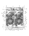
(プリンタ100の内部構成)
つぎに、この発明にかかる実施の形態1のプリンタ100の内部構成について説明する。図2は、図1のA−A断面図である。図2において、第1のプリントユニット110および第2のプリントユニット120は、それぞれ、記録対象となる記録媒体を保持する保持部201、202を備えている。第1の保持部201および第2の保持部202は、同様の構成をなしている。この実施の形態1において、第1の保持部201は、この発明にかかる保持部を実現する。
(Internal configuration of printer 100)
Next, the internal configuration of the
第1の保持部201および第2の保持部202は、図2における紙面表裏方向を軸心方向とし、軸心周りに回転可能に設けられた保持軸201a、202aを備えている。第1の保持部201および第2の保持部202は、長尺状をなし長さ方向に沿ってロール状に巻回された記録媒体の巻き取り中心となる巻き取り芯を保持軸201a、202aによって保持する。これにより、第1の保持部201および第2の保持部202は、それぞれ、巻回された状態の長尺状の記録媒体を、外周側の端部から引き出し可能な状態で保持している。この実施の形態1において、第2の保持部202が保持する記録媒体は、この発明にかかる別の記録媒体を実現する。
The
記録媒体は、記録層を備えている。記録媒体が備える記録層は、紙などによって形成される基材の表面に設けられている。記録層は、基材に塗布、あるいは貼り合わされる断熱層と、当該断熱層に積層される受容層と、によって構成されている。第1の保持部は、たとえば、基材の両方の面にそれぞれ記録層が設けられた記録媒体を保持する。第2の保持部は、たとえば、基材の一方の面にのみ記録層が設けられた記録媒体を保持する。 The recording medium includes a recording layer. The recording layer provided in the recording medium is provided on the surface of a substrate formed of paper or the like. The recording layer is composed of a heat insulating layer applied or bonded to a substrate and a receiving layer laminated on the heat insulating layer. A 1st holding | maintenance part hold | maintains the recording medium with which the recording layer was each provided in both surfaces of the base material, for example. The second holding unit holds, for example, a recording medium provided with a recording layer only on one surface of the substrate.
第1のプリントユニット110および第2のプリントユニット120は、それぞれ、記録対象となる記録媒体(印画紙)に対する記録動作をおこなう記録部203、204を備えている。第1のプリントユニット110が備える記録部(以下、「第1の記録部」という)203および第2のプリントユニット120が備える記録部(以下、「第2の記録部」という)204は、同様の構成をなし、それぞれ、サーマルヘッド203a、204aとプラテン203b、204bとを備えている。この実施の形態1において、第1の記録部203は、この発明にかかる記録部を実現する。
Each of the
第1のプリントユニット110は、ハウジング110a内に、第1の保持部201から第1の記録部203を経由して第1の排出口205へ連通する第1の搬送経路206を備えている。第1の搬送経路206には、当該第1の搬送経路206における記録媒体を搬送する搬送用のローラ対(図示を省略する)が設けられている。搬送用のローラ対は、第1の搬送経路206を間にして対向配置された、対をなすローラによって構成されている。搬送用のローラ対は、第1の搬送経路206において、一ないし複数設けられている。
The
第1の記録部203におけるサーマルヘッド(以下、「第1のサーマルヘッド」という)203aおよびプラテン(以下、「第1のプラテン」という)203bは、第1の搬送経路206を間にして対向配置されている。第1の記録部203において、第1のサーマルヘッド203aは、第1のプラテン203bに接触する位置と第1のプラテン203bから離間する位置とに移動可能に設けられている。
A thermal head (hereinafter referred to as a “first thermal head”) 203 a and a platen (hereinafter referred to as a “first platen”) 203 b in the
第1のプラテン203bは、記録媒体の幅方向を軸心方向とする円筒形状をなし、軸心周りに回転可能に設けられている。第1のプラテン203bは、図2における紙面反時計回り方向(正方向)、および、図2における紙面時計回り方向(逆方向)に回転可能に設けられている。
The
第1のプラテン203bには、図示を省略するモータが、所定の輪列を介して連結されている。第1のプラテン203bは、所定の輪列を介して連結されたモータの駆動力が伝達されることにより接触する記録媒体の動きに合わせて、受動的に回転しながら、記録媒体を挟んで対向する第1のサーマルヘッド203aが記録媒体にかける圧力を受け止める。
A motor (not shown) is connected to the
第2のプリントユニット120は、ハウジング120a内に、第2の保持部202から第2の記録部204を経由して第2の排出口207へ連通する第2の搬送経路208を備えている。第2の搬送経路208は、第2の保持部202を間にして第2の記録部204とは反対側に延びており、第2のプリントユニット120のハウジング120aに設けられた挿入口209に連通されている。このため、第2の搬送経路208は、挿入口209から、第2の保持部202および第2の記録部204を経由して第2の排出口207に連通されている。
The
第2の記録部204におけるサーマルヘッド(以下、「第2のサーマルヘッド」という)204aおよびプラテン(以下、「第2のプラテン」という)204bは、第2の搬送経路208を間にして対向配置されている。第2の記録部204において、第2のサーマルヘッド204aは、第2のプラテン204bに接触する位置と第2のプラテン204bから離間する位置とに移動可能に設けられている。
A thermal head (hereinafter referred to as “second thermal head”) 204 a and a platen (hereinafter referred to as “second platen”) 204 b in the
第2のプラテン204bは、第1のプラテン203bと同様に、記録媒体の幅方向を軸心方向とする円筒形状をなし、軸心周りに回転可能に設けられている。第2のプラテン204bは、第1のプラテン203bと同様に、図2における紙面反時計回り方向(正方向)および図2における紙面時計回り方向(逆方向)に回転可能に設けられている。
Similar to the
第2のプラテン204bには、図示を省略するモータが、所定の輪列を介して連結されている。第2のプラテン204bは、接触する記録媒体の動きに合わせて、受動的に回転しながら、記録媒体を挟んで対向する第2のサーマルヘッド204aが記録媒体にかける圧力を受け止める。
A motor (not shown) is connected to the
第1のサーマルヘッド203aおよび第2のサーマルヘッド204aは、いずれも、記録媒体の幅方向(図2における紙面表裏方向)に沿ってライン状に配列された複数の発熱素子(発熱抵抗体)や、当該発熱素子を駆動するドライバICなどを備えている(図3を参照)。各ドライバICは、第1のプリントユニット110および第2のプリントユニット120がそれぞれ備えるマイクロコンピュータ(図3を参照)によって駆動制御される。ドライバICは、マイクロコンピュータによって駆動制御されることにより、図示を省略する電源から、第1のサーマルヘッド203aおよび第2のサーマルヘッド204aにおける各発熱素子に接続された電極配線に選択的に通電することによって、通電された電極配線に対応する発熱素子を発熱させる。
Each of the first
第1のプリントユニット110および第2のプリントユニット120が備えるマイクロコンピュータは、それぞれ、第1のプリントユニット110および第2のプリントユニット120に設けられた制御基板に搭載されている。各制御基板は、第1のプリントユニット110および第2のプリントユニット120が備える各部を駆動制御する。
The microcomputers provided in the
また、第1のプリントユニット110および第2のプリントユニット120は、それぞれ、リボンユニット210、211を備えている。リボンユニット210、211は、同様の構成をなしている。
Further, the
具体的に、第1のプリントユニット110が備えるリボンユニット210は、インクリボンを保持する一対のローラ210a、210bを備えている。一対のローラ210a、210bは、第1のサーマルヘッド203aと第1のプラテン203bとの間において、インクリボンが張り渡されるようにして当該インクリボンを保持する。一対のローラ210a、210bは、第1のサーマルヘッド203aと第1のプラテン203bとの間において、インクリボンにおけるインク層が第1のプラテン203bに対向する状態で、当該インクリボンを保持する。
Specifically, the
リボンユニット210における一対のローラ210a、210bは、巻き取りローラ210aと供給ローラ210bとによって構成される。巻き取りローラ210aは、図2における時計回り方向に回転可能に設けられており、回転することによって供給ローラ210bが保持するインクリボンを、当該インクリボンの一端側から巻き上げる。供給ローラ210bは、巻回された長尺状のインクリボンを、当該インクリボンの外周側から繰り出し可能に保持する。供給ローラ210bは、巻き取りローラ210aが回転することによるインクリボンの巻き上げにともなって、図2における時計回り方向に回転し、インクリボンを外周側から繰り出す。
The pair of
また、具体的に、第2のプリントユニット120が備えるリボンユニット211は、インクリボンを保持する一対のローラ211a、211bを備えている。一対のローラ211a、211bは、第2のサーマルヘッド204aと第2のプラテン204bとの間において、インクリボンが張り渡されるようにして当該インクリボンを保持する。一対のローラ211a、211bは、第2のサーマルヘッド204aと第2のプラテン204bとの間において、インクリボンにおけるインク層が第2のプラテン204bに対向する状態で、当該インクリボンを保持する。
Specifically, the
巻き取りローラ211aは、図2における時計回り方向に回転可能に設けられており、回転することによって供給ローラ211bが保持するインクリボンを、当該リボンの一端側から巻き上げる。供給ローラ211bは、巻回された長尺状のインクリボンを、当該インクリボンの外周側から繰り出し可能に保持する。供給ローラ210bは、巻き取りローラ211aが回転することによるインクリボンの巻き上げにともなって、図2における時計回り方向に回転し、インクリボンを外周側から繰り出す。
The take-up
各リボンユニット210、211が保持するインクリボンは、それぞれ、長尺状の基材と、当該基材の一面側に設けられたインク層を備えている。インク層は、昇華性染料インク(昇華性染料(昇華性色素、熱拡散性色素)を含有するインク、すなわち昇華インク)によって形成されている。具体的に、インクリボンは、イエロー(Y)、マゼンタ(M)およびシアン(C)の各色のインク層を備える。各インク層は、それぞれ、昇華性染料インク(昇華性染料(昇華性色素)を含有するインク、すなわち昇華インク)によって形成されている。
Each of the ink ribbons held by the
インクリボンにおいて、複数色のインク層は、色ごとに、基材の長さ方向に沿って周期的に配置されている。具体的には、たとえば、イエロー(Y)、マゼンタ(M)およびシアン(C)の各インク層は、基材の長さ方向に沿って「イエロー(Y)のインク層→マゼンタ(M)のインク層→シアン(C)のインク層→・・・」の順序で周期的に配置されている。 In the ink ribbon, the ink layers of a plurality of colors are periodically arranged along the length direction of the substrate for each color. Specifically, for example, each of the yellow (Y), magenta (M), and cyan (C) ink layers is “yellow (Y) ink layer → magenta (M)” along the length direction of the substrate. The ink layers are periodically arranged in the order of ink layer → cyan (C) ink layer →.
また、インクリボンは、オーバーコート層を備えている。オーバーコート層は、インク層とともに、基材の長さ方向に沿って周期的に配置されている。具体的に、インクリボンにおいては、基材の長さ方向に沿って、「イエロー(Y)のインク層→マゼンタ(M)のインク層→シアン(C)のインク層→オーバーコート層→イエロー(Y)のインク層→・・・」の順序で周期的に配置されている。 The ink ribbon includes an overcoat layer. The overcoat layer is periodically arranged along with the length of the substrate together with the ink layer. Specifically, in the ink ribbon, along the length direction of the substrate, “yellow (Y) ink layer → magenta (M) ink layer → cyan (C) ink layer → overcoat layer → yellow ( The ink layers are arranged in the order of “Y) ink layer →.
第1のプリントユニット110および第2のプリントユニット120は、それぞれ、昇華転写方式の記録動作をおこなう。昇華転写方式の記録動作は、サーマルヘッド203a、204aにおける発熱素子に対して選択的に通電することにより発熱素子を選択的に発熱させ、発熱素子において発生した熱をインクリボンに伝達し、記録対象とする記録媒体における記録層に対して、インクリボンが備えるインク層に含有される昇華性染料インクを記録媒体に昇華転写することによっておこなう。各記録媒体における受容層は、インクリボンが備えるインク層に含有される昇華性染料インクの転写を受け付ける。このような昇華転写方式の記録動作をおこなうプリンタ100は、たとえば、昇華型プリンタ(Dye−sublimation printer)などと称される。
The
昇華型プリンタは、記録媒体に転写するインクの濃度を、記録するドットごとに調整することができる。このため、昇華型プリンタは、階調表現に優れている。優れた階調表現ができることから、昇華型プリンタは、写真印刷用途にも耐えうる画質を得ることができる。このため、昇華型プリンタは、近年、DTP(DeskTop Publishing)用途にも用いられている。 The sublimation printer can adjust the density of the ink transferred to the recording medium for each dot to be recorded. For this reason, the sublimation printer is excellent in gradation expression. Since excellent gradation expression can be achieved, the sublimation printer can obtain an image quality that can withstand photographic printing. For this reason, in recent years, sublimation printers are also used for DTP (Desk Top Publishing) applications.
また、第1のプリントユニット110および第2のプリントユニット120は、それぞれ、記録動作に際して、記録動作をおこなった記録媒体の表面(記録面)に、当該記録面を覆うようにしてオーバーコート層を設けることによってラミネート処理を施す。これにより、記録物における昇華性染料インクの耐水性能や耐候性能の劣化を抑制し、記録物の耐水性や耐候性を高めることができる。記録媒体の両面に対して記録動作をおこなう場合、片面に対する記録動作ごとにオーバーコート層を設ける。
Further, each of the
第1のプリントユニット110および第2のプリントユニット120は、それぞれ、グリップローラ212とピンチローラ213とを備えている。グリップローラ212とピンチローラ213とは、それぞれ、第1の搬送経路206および第2の搬送経路208を間にして対向配置されている。
Each of the
グリップローラ212は、それぞれ、第1の記録部203および第2の記録部204による記録動作中の記録媒体の記録面の裏面側に設けられている。ピンチローラ213は、それぞれ、対向配置されたグリップローラ212に対して当接する方向に付勢されている。これにより、グリップローラ212とピンチローラ213とによって、第1の搬送経路206および第2の搬送経路208を搬送される記録媒体を挟持することができる。
The
グリップローラ212は、外周方向に突出した突起(図示を省略する)を有する。これにより、グリップローラ212と記録媒体とがスリップすることを防止できる。グリップローラ212およびピンチローラ213が記録媒体を挟持して搬送できる力(グリップ力)は、記録媒体が第1の記録部203および第2の記録部204や、第1の搬送経路206や第2の搬送経路208から受ける負荷よりも十分大きく確保する。これにより、グリップローラ212と記録媒体とがスリップすることを確実に防止できる。
The
各グリップローラ212には、モータ(図3を参照)が、所定の輪列を介して連結されている。これにより、グリップローラ212とピンチローラ213との間に記録媒体を挟持した状態で、グリップローラ212を回転させることができる。グリップローラ212とピンチローラ213との間に記録媒体を挟持した状態で、グリップローラ212を回転させることにより、第1のサーマルヘッド203aおよび第1のプラテン203b、および、第2のサーマルヘッド204aおよび第2のプラテン204bによる記録位置に対する当該記録媒体の位置を制御できる。
A motor (see FIG. 3) is connected to each
また、第1のプリントユニット110において、グリップローラ212の近傍には、第1の保持部201から第1の搬送経路206に引き出された記録媒体の先端位置を検出する第1の記録媒体検出センサ(図3における符号318を参照)が設けられている。第1の記録媒体検出センサは、たとえば、第1の搬送経路206を間にして対向配置された発光素子と受光素子とを備え、受光素子における受光量の変化に応じて変動する光センサによって実現することができる。
Further, in the
第1のプリントユニット110は、第1の搬送経路206中を搬送される記録媒体が発光素子と受光素子との間を通過することによって受光素子における受光量が変化し、この受光量の変化に応じて変動する第1の記録媒体検出センサの出力値に基づいて、第1の保持部201から第1の搬送経路206に引き出された記録媒体の先端位置を検出することができる。
In the
また、第2のプリントユニット120においても、グリップローラ212の近傍には、第1のプリントユニット110と同様に、第2の保持部202から第2の搬送経路208中に引き出された記録媒体の先端位置を検出する第2の記録媒体検出センサ(図3における符号328を参照)が設けられている。第2の記録媒体検出センサは、第1の記録媒体検出センサと同様に、第2の搬送経路208を間にして対向配置された発光素子と受光素子とを備えた光センサによって実現することができる。
Also in the
このように、グリップローラ212の近傍に第1の記録媒体検出センサや第2の記録媒体検出センサを設けることにより、第1の記録部203や第2の記録部204における記録動作に際して、記録媒体に対する各色の記録位置を精度よく合わせることができ、品質の高い記録物を得ることができる。
As described above, by providing the first recording medium detection sensor and the second recording medium detection sensor in the vicinity of the
また、第1のプリントユニット110において、第1の排出口205の近傍には、第1のカッタ機構214が設けられている。第1のカッタ機構214は、位置が固定された固定刃と、固定刃に沿って記録媒体の幅方向に移動(往復移動)可能に設けられた可動刃と、を備えている(いずれも図示を省略する)。可動刃は、固定刃と接触しており、第1の搬送経路206を分断する位置に設けられている。可動刃は、外周部分に刃を備えた円板形状をなし、固定刃に沿って記録媒体の幅方向に移動(往復移動)可能に設けられている。可動刃は、記録媒体の切断を待機している場合などの非動作時は、記録媒体の通過に支障のない位置に位置付けられる。
In the
第1のカッタ機構214は、可動刃駆動用のモータなどの駆動源や、当該可動刃駆動用のモータが発生させた駆動力を可動刃に伝達する動力伝達機構(いずれも図示を省略する)などを備えている。第1のカッタ機構214は、記録媒体における切断位置(すなわち切断対象とする位置)が、第1の搬送経路206において可動刃が当該第1の搬送経路206を横断するように移動(往復移動)する位置(すなわち第1のカッタ機構214による切断位置)まで搬送された状態で、可動刃駆動用のモータが発生させた駆動力によって可動刃を記録媒体の幅方向に移動させることによって記録媒体を切断する。
The
第1のプリントユニット110において、第1のカッタ機構214における切断位置の近傍には、記録媒体の有無に応じて出力値が変化する第1の切断位置検出センサ(図3における符号319を参照)が設けられている。第1の切断位置検出センサは、たとえば、上記の第1の記録媒体検出センサと同様に、第1の搬送経路206を間にして対向配置された発光素子と受光素子とを備え、受光素子における受光量の変化に応じて変動する光センサによって実現することができる。
In the
第1のプリントユニット110において、第1のカッタ機構214の鉛直方向下側には、第1のカッタ機構214によって記録媒体を切断する際に生じた断裁片(カットくず)を収容する第1の断裁片収容部215が設けられている。第1の断裁片収容部215は、第1のカッタ機構214側に開口する開口部(図示を省略する)を備えており、第1のプリントユニット110のハウジング110aに対して着脱可能に設けられている。
In the
第1のプリントユニット110は、記録対象とする記録媒体が、ハウジング110a内において第1の搬送経路206中を搬送されるように、当該記録媒体の位置をガイドする第1のガイド部材216を備えている。第1のガイド部材216は、第1の保持部201から引き出した記録媒体が、第1の記録部203を経由して第1のカッタ機構214に搬送されるように、当該記録媒体の位置をガイドする。
The
第2のプリントユニット120において、第2の排出口207の近傍には、第2のカッタ機構217が設けられている。第2のカッタ機構217は、第1のカッタ機構214と同様の構成をなし、固定刃、可動刃、駆動源および動力伝達機構などを備えている。また、第2のプリントユニット120において、第2のカッタ機構217における切断位置の近傍には、記録媒体の有無に応じて出力値が変化する第2の切断位置検出センサ(図3における符号329を参照)が設けられている。第2の切断位置検出センサは、たとえば、上記の第1の記録媒体検出センサや第1の切断位置検出センサと同様に、第2の搬送経路208を間にして対向配置された発光素子と受光素子とを備え、受光素子における受光量の変化に応じて変動する光センサによって実現することができる。
In the
また、第2のプリントユニット120において、第2のカッタ機構217の鉛直方向下側には、第2の断裁片収容部218が設けられている。第2の断裁片収容部218は、第1の断裁片収容部215と同様の構成をなし、第2のカッタ機構217側に開口する開口部(図示を省略する)を備え、第2のプリントユニット120のハウジング120aに対して着脱可能に設けられている。
In the
第2のプリントユニット120は、記録対象とする記録媒体が、ハウジング120a内において第2の搬送経路208中を搬送されるように、当該記録媒体の位置をガイドする第2のガイド部材219を備えている。第2のガイド部材219は、第2の保持部202から引き出した記録媒体が、第2の記録部204を経由して第2のカッタ機構217に搬送されるように当該記録媒体の位置をガイドする。
The
また、第2のプリントユニット120は、挿入口209を介して第1のプリントユニット110側から搬送される記録媒体が、第2の記録部204に搬送されるように当該記録媒体の位置をガイドするガイド部材219を備えている。このガイド部材219において、第2の記録部204側の端部には、切替部材220が設けられている。
Further, the
切替部材220は、第2の記録部204に供給される記録媒体の種類に応じて、連続紙用の位置と切断紙用の位置とに選択的に位置付けられる。切替部材220は、第2の保持部202が保持する記録媒体に対する記録動作をおこなう場合に連続紙用の位置に位置付けられ、挿入口209から第2の記録部204へ至る経路を閉塞する。また、切替部材220は、挿入口209を介して第1のプリントユニット110側から搬送される記録媒体に対する記録動作をおこなう場合に切断紙用の位置に位置付けられ、第2の保持部202から第2の記録部204へ至る経路を閉塞する。
The switching
第2のプリントユニット120において、挿入口209の近傍には、記録媒体の有無に応じて出力値が変化する挿入検知センサ(図3における符号330を参照)が設けられており、切替部材220は、この挿入検知センサの出力値に応じて連続紙用の位置と切断紙用の位置とに選択的に位置付けられる。具体的に、切換部材は、挿入検知センサが記録媒体を検出していない場合は連続紙用の位置に位置付けられ、当該挿入検知センサが記録媒体を検出した場合は切断紙用の位置に位置付けられる。
In the
第1の搬送ユニット130のハウジング130aには、第1の排出口205に対向する位置(第1のプリントユニット110からの記録媒体の排出位置)に設けられた第1の開口221と、トレイ150に対向する位置に設けられた第2の開口222と、第2の搬送ユニット140に対向する位置に設けられた第3の開口223と、を連通する反転経路224が設けられている。反転経路224は、第2の開口222と第3の開口223とを連通する経路224aと、当該経路224aにおける第1の開口221の近傍から分岐して第1の開口221に連通する経路224bと、によって構成され、略T字形状をなしている。
The
反転経路224において、経路224aと経路224bとの分岐位置よりも第2の開口222側には、搬送ローラ対225が設けられている。搬送ローラ対225を構成する一対のローラ225a、225bのうちの一方のローラ225aには、当該一方のローラ225aを駆動するためのモータなどの駆動源(図3を参照)が連結され、当該駆動源が発生させた駆動力を一方のローラ225aに伝達する動力伝達機構(図示を省略する)が連結されている。
In the reversing
一方のローラ225aを駆動するためのモータは、正方向および逆方向のいずれの方向にも回転可能とされている。これにより、一方のローラ225aは、第1の開口221側から第2の開口222側に向けて記録媒体を搬送する方向(以下、適宜「第1の回転方向」という)と、第2の開口222側から第3の開口223側に向けて記録媒体を搬送する方向(以下、適宜「第2の回転方向」という)と、のいずれの方向にも回転することができる。一方のローラ225aは、一方のローラ225aを駆動するためのモータの回転方向に応じた方向に回転する。
The motor for driving one
搬送ローラ対225を構成する一対のローラ225a、225bのうちの他方のローラ225bは、図示を省略する付勢部材によって、一方のローラ225aに当接する方向に付勢されている。これにより、搬送ローラ対225における一対のローラ225a、225bは、互いに外周面の一部を当接させた状態で設けられている。そして、これにより、搬送ローラ対225における他方のローラ225bは、一方のローラ225aとの摩擦によって、当該一方のローラ225aの回転にともなって当該一方のローラ225aの回転方向とは反対方向に回転する。
The
搬送ローラ対225は、外周面の一部を互いに当接させた一対のローラ225a、225bの間に、記録媒体を挟持する。一対のローラ225a、225bの間に記録媒体を挟持した状態においては、記録媒体は、他方のローラ225bによって一方のローラ225aに当接する方向に付勢される。この状態で一方のローラ225aが回転すると、当該一方のローラ225aと記録媒体との摩擦によって、当該一方のローラ225aの回転方向に応じた方向に記録媒体を搬送することができる。
The conveying
搬送ローラ対225は、第1のプリントユニット110において、もっとも第1の排出口205側に設けられた搬送用のローラ対までの距離が、外部装置(図3における符号300を参照)から受信した記録指示に基づいて特定される記録物の寸法よりも短くなる位置に設けられている。これにより、プリンタ100における記録媒体に対して、常に搬送力を付与することができ、第1のプリントユニット110から排出された記録媒体が第1の搬送ユニット130内で停滞してしまうことを防止できる。この実施の形態1においては、搬送ローラ対225によって、この発明にかかる搬送部を実現することができる。
The
また、搬送ローラ対225は、当該搬送ローラ対225によって記録媒体を挟持する位置から、第2のプリントユニット120のハウジング120aに設けられた挿入口209までの距離が、外部装置から受信した記録指示に基づいて特定される記録物の寸法よりも短くなる位置に設けられている。これにより、プリンタ100における記録媒体に対して、常に搬送力を付与することができ、第1の搬送ユニット130から第2の搬送ユニット140に搬送された記録媒体が、第1の搬送ユニット130内または第2の搬送ユニット140内で停滞してしまうことを防止できる。また、これにより、第2の搬送ユニット140に、記録媒体を搬送するローラ対などの搬送手段を設けることなく、第1の搬送ユニット130から第2のプリントユニット120に記録媒体を搬送することができる。
Further, the
反転経路224において、経路224aと経路224bとの分岐位置には、振り分け部226が設けられている。振り分け部226は、第1の開口221を介して第1の排出口205に対向する位置に設けられている。振り分け部226は、具体的には、たとえば、一端が固定され、当該一端を支点として他端が揺動可能に設けられたフラップ状部材によって実現することができる。この実施の形態1においては、以下、振り分け部226を実現するフラップ状部材に、符号226を付して説明する。
In the
フラップ状部材226の位置は、固定された一端を支点として揺動することにより、第1の開口221と第2の開口222とを連通する第1の位置と、第2の開口222と第3の開口223とを連通する第2の位置と、に自在に切り替えることができる。
The position of the flap-shaped
第2の搬送ユニット140のハウジング140aには、第3の開口223に対向する位置に設けられた第4の開口227と、第2のプリントユニット120のハウジング120aに設けられた挿入口209に対向する位置に設けられた第5の開口228と、を連通する案内経路229が設けられている。また、第2の搬送ユニット140は、案内経路229中を搬送される記録媒体の位置をガイドするガイド部材230を備えている。この実施の形態1においては、案内経路229やガイド部材230によって、この発明にかかる案内部を実現することができる。
The
第2の搬送ユニット140のハウジング140a内には、第2の排出口207と排出口141とを連通する排出用の経路231が設けられている。排出用の経路231には、当該排出用の経路231を間にして対向配置された一対のローラ232が設けられている。一対のローラ232は、互いに外周面の一部を当接させた状態で設けられており、当接している部分において記録媒体を挟持する。
A
一対のローラ232は、モータなどの動力源には連結されておらず、第2のプリントユニット120から排出された記録媒体が、一対のローラ232の間に挟まれた状態で当該記録媒体がさらに搬送された場合に、当該記録媒体に連れ回されて回転する。一対のローラ232を設けることにより、排出口141において記録媒体を保持することができる。
The pair of
(プリンタ100のハードウエア構成)
つぎに、この発明にかかる実施の形態1のプリンタ100のハードウエア構成について説明する。図3は、この発明にかかる実施の形態1のプリンタ100のハードウエア構成を示す説明図である。図3において、プリンタ100は、第1の制御系310と、第2の制御系320と、を備えている。第1の制御系310は、第1のプリントユニット110が備える各部を駆動制御する。第2の制御系320は、第2のプリントユニット120が備える各部を駆動制御する。第1の制御系310および第2の制御系320は、それぞれ独立しており、制御対象とする各部をそれぞれ独立して駆動制御する。
(Hardware configuration of printer 100)
Next, a hardware configuration of the
第1の制御系310は、第1のマイクロコンピュータ311と、第1の通信I/F(インターフェイス)312と、第1のドライバIC313と、第1のモータドライバ314と、第1の入力I/F315と、を備えている。第1のマイクロコンピュータ311、第1の通信I/F312、第1のドライバIC313、第1のモータドライバ314、第1の入力I/F315の各部は、バス316によって接続されている。
The
第1のマイクロコンピュータ311は、第1のプリントユニット110が備える各部を駆動制御する。第1のマイクロコンピュータ311は、たとえば、CPU、ROMやRAMなどのメモリ、入出力回路やタイマー回路などの各種回路を実装した基板によって実現することができる。
The first microcomputer 311 drives and controls each unit included in the
第1のマイクロコンピュータ311は、当該第1のマイクロコンピュータ311が備えるメモリに記憶された各種データや第1の通信I/F312を介して外部装置300から受信した各種データに基づいて、当該メモリに記憶された各種の制御プログラムをCPUにおいて実行することによって第1のプリントユニット110が備える各部を駆動制御する。第1のマイクロコンピュータ311において、CPUは、たとえば、記録命令情報に基づく印刷にかかるイメージデータを展開する際のワークエリアとしてRAMを使用する。
The first microcomputer 311 stores data in the memory based on various data stored in the memory included in the first microcomputer 311 and various data received from the
第1の通信I/F312は、外部装置300に接続されている。第1の通信I/F312は、外部装置300と直接接続されていてもよく、ネットワークを介して接続されていてもよい。第1の通信I/F312は、外部装置300と第1のプリントユニット110の内部とのインターフェイスをつかさどり、第1の制御系310におけるデータの入出力を制御する。
The first communication I / F 312 is connected to the
第1のドライバIC313は、第1のマイクロコンピュータ311によって駆動制御される。第1のドライバIC313は、第1のマイクロコンピュータ311によって駆動制御されることにより、第1の記録部203における第1のサーマルヘッド203aが備える複数の発熱素子のそれぞれに対応する電極配線に対して選択的に通電する。これにより、各発熱素子を選択的に発熱させることができる。第1のサーマルヘッド203aの発熱素子において発生した熱をインクリボンを介して記録媒体の記録層に伝達することによって、当該インクリボンに設けられた昇華性染料インクを記録媒体に昇華転写し、記録媒体に対する記録動作をおこなうことができる。
The first driver IC 313 is driven and controlled by the first microcomputer 311. The first driver IC 313 is driven and controlled by the first microcomputer 311 so that the electrode wiring corresponding to each of the plurality of heating elements included in the first
第1のモータドライバ314は、第1のマイクロコンピュータ311によって駆動制御される。第1のモータドライバ314には、第1のプラテン203bに連結されたモータ、第1のプリントユニット110におけるグリップローラ212に連結されたモータ、第1のカッタ機構214における可動刃駆動用のモータ、および、第1のプリントユニット110におけるローラ対などの搬送手段に連結されたモータなどの各種モータ317が接続されている。第1のモータドライバ314は、第1のマイクロコンピュータ311からの制御信号に基づいて、第1のモータドライバ314に接続された各種モータ317を駆動制御する。
The first motor driver 314 is driven and controlled by the first microcomputer 311. The first motor driver 314 includes a motor coupled to the
第1の入力I/F315には、第1の記録媒体検出センサ318や第1の切断位置検出センサ319などの各種センサが接続されている。各種センサは、USB(Universal Serial Bus)により第1の入力I/F315に接続されていてもよい。
Various sensors such as a first recording
第1の入力I/F315は、第1の記録媒体検出センサ318や第1の切断位置検出センサ319などの各種センサからの出力値に応じた信号を、第1のマイクロコンピュータ311に出力する。第1のマイクロコンピュータ311には、第1の入力I/F315から出力された信号に基づいて、第1のプリントユニット110が備える各部を駆動制御する。
The first input I / F 315 outputs a signal corresponding to an output value from various sensors such as the first recording
第2の制御系320は、第2のマイクロコンピュータ321と、第2の通信I/F322と、第2のドライバIC323と、第2のモータドライバ324と、第2の入力I/F325と、を備えている。第2のマイクロコンピュータ321、第2の通信I/F322、第2のドライバIC323、第2のモータドライバ324、第2の入力I/F325の各部は、バス326によって接続されている。
The
第2の制御系320が備える第2のマイクロコンピュータ321、第2の通信I/F322、第2のドライバIC323、第2のモータドライバ324、第2の入力I/F325は、第1の制御系310における第1のマイクロコンピュータ311、第1の通信I/F312、第1のドライバIC313、第1のモータドライバ314、第1の入力I/F315と同様に構成されている。
The second microcomputer 321, the second communication I / F 322, the
第2の入力I/F325には、第2の記録媒体検出センサ328、第2の切断位置検出センサ329、挿入検知センサ330などの各種センサが接続されている。各種センサは、USB(Universal Serial Bus)により第2の入力I/F325に接続されていてもよい。
Various sensors such as a second recording
外部装置300は、たとえば、プリンタ100に対する記録指示を生成し、生成した記録指示をプリンタ100に対して出力する。外部装置300は、具体的には、デジタルカメラで撮影した画像をプリント出力するサービスを提供するDPE店などに設置されたパーソナルコンピュータによって実現することができる。
For example, the
記録指示は、たとえば、記録媒体に記録する画像などに関する情報や、当該情報の記録を指示するコマンドなどを含む。具体的に、外部装置300は、記録指示として、記録媒体の片面に対する記録動作(片面記録)を指示する片面記録指示や、記録媒体の両面に対する記録動作(両面記録)を指示する両面記録指示を出力する。
The recording instruction includes, for example, information related to an image to be recorded on a recording medium, a command for instructing recording of the information, and the like. Specifically, the
外部装置300は、両面記録指示の出力に際しては、第1のプリントユニット110および第2のプリントユニット120に、それぞれ、片面記録指示を出力する。すなわち、外部装置300は、両面記録指示の出力に際して、記録媒体の両面に設けられた記録面のうちの一方の記録面(たとえば、おもて面)に記録する画像に関する情報を含む記録指示(以下、適宜「おもて面用の記録指示」という)を第1のプリントユニット110に対して出力し、記録媒体の両面に設けられた記録面のうちの他方の記録面(たとえば、裏面)に記録する画像に関する情報を含む記録指示(以下、適宜「裏面用の記録指示」という)を第2のプリントユニット120に対して出力することによって両面記録指示の出力を実現する。
When outputting the double-sided recording instruction, the
両面記録指示の出力に際して外部装置300が第2のプリントユニット120に対して出力する裏面用の記録指示は、第2の保持部202が保持する記録媒体ではなく、挿入口209を介して挿入された記録媒体に対する記録動作の指示を含む。あるいは、裏面用の記録指示は、両面記録に際して、第2の保持部202が保持する記録媒体の巻き取り芯が回転しないように、当該巻き取り芯の回転を規制する指示を含むものであってもよい。
The back side recording instruction output from the
外部装置300によるプリンタの制御は、外部装置300にインストールされたプリンタドライバによっておこなってもよく、DLL(Dynamic Link Library)によっておこなってもよい。DLLファイルはそれ単体では実行することができないライブラリ(汎用性の高い複数のプログラム)であって、記録動作時などの各プリントユニットの動作時に自動的に連結されてメモリ上に展開される。プリンタにおけるDLLは、各プリントユニットの動作時に共通して必要とするプログラムによって実現することができる。
Control of the printer by the
(プリンタ100がおこなう記録動作)
つぎに、この発明にかかる実施の形態1のプリンタ100がおこなう記録動作について説明する。上述したように、プリンタ100は、記録媒体に対して、片面記録および両面記録をおこなうことができる。
(Recording operation performed by the printer 100)
Next, a recording operation performed by the
(片面記録)
まず、プリンタ100がおこなう記録動作として、片面記録にかかる記録動作について説明する。図4、図5、図6および図7は、この発明にかかる実施の形態1のプリンタ100がおこなう記録動作のうち、片面記録にかかる記録動作を示す説明図である。
(Single-sided recording)
First, as a recording operation performed by the
片面記録に際して、プリンタ100は、まず、外部装置300から、片面記録指示を受信する。片面記録指示は、第2のプリントユニット120に入力される。片面記録指示を受信した第2のプリントユニット120は、切替部材220を、連続紙用の位置に位置付ける(図4を参照)。
When performing single-sided recording, the
片面記録指示を受信した第2のプリントユニット120は、第2の保持部202が保持する記録媒体を第2の搬送経路208に引き出す方向に、第2のプリントユニット120における搬送用のローラ対を回転させる。これにより、第2の保持部202が保持する記録媒体が、第2の保持部202から第2の搬送経路208に引き出される(図4を参照)。第2の保持部202から第2の搬送経路208に引き出された記録媒体の先端位置は、第2の記録媒体検出センサ328の出力値に基づいて検出することができる。
Receiving the single-sided recording instruction, the
そして、検出した記録媒体の先端位置に基づいて、さらに、第2のプリントユニット120における搬送用のローラ対を回転させるとともに、グリップローラ212を正回転方向に回転させる。搬送用のローラ対およびグリップローラ212は、先端位置が検出された記録媒体の当該先端位置が、あらかじめ設定された記録動作の開始位置(印刷開始位置)に到達するまで、正方向に回転させる。
Then, based on the detected front end position of the recording medium, the conveyance roller pair in the
第2のプリントユニット120における記録動作の開始位置(印刷開始位置)は、第2の搬送経路208に引き出した記録媒体の先端から第2の記録部204の記録位置までの長さが、外部装置300から受信した片面記録指示に基づいて特定される記録物の寸法よりも長くなる位置に設定することができる。第2のプリントユニット120は、長尺状の記録媒体を第2の保持部202から引き出す際には、第2のサーマルヘッド204aを第2のプラテン204bから離間させる。
The start position (print start position) of the recording operation in the
つぎに、第2のプリントユニット120は、第2のサーマルヘッド204aを第2のプラテン204b側に移動させ、第2のサーマルヘッド204aと第2のプラテン204bとによって記録媒体およびインクリボンを挟持する。この状態で、第2の保持部202から第2の搬送経路208に引き出した長尺状の記録媒体を、第2の保持部202に引き込む方向に搬送しながら、片面記録指示に基づいて、第2のサーマルヘッド204aが備える発熱素子を選択的に発熱させる(図5を参照)。これにより、第2のサーマルヘッド204aが備える発熱素子において発生した熱がインクリボンに伝達され、当該インクリボンに設けられた昇華性染料インクが記録媒体に昇華転写され、記録媒体に対する記録動作をおこなうことができる。
Next, the
上記の記録動作は、インク層の色ごとに、YMC面順次印刷をおこなう。具体的には、たとえば、1色目(たとえばイエロー(Y))の記録動作をおこない、つぎに2色目(たとえばマゼンタ(M))の記録動作をおこない、そのつぎに3色目(シアン(C))の記録動作をおこなう。プリンタ100は、各色の記録動作をおこなうごとに、当該記録動作により第2の保持部202に引き込まれた記録媒体の先端が、再び印刷開始位置に到達するまで、当該記録媒体を第2の搬送経路208に引き出す。
In the above recording operation, YMC plane sequential printing is performed for each color of the ink layer. Specifically, for example, the recording operation for the first color (for example, yellow (Y)) is performed, the recording operation for the second color (for example, magenta (M)) is performed, and then the third color (cyan (C)) is performed. Perform the recording operation. Each time the
具体的には、1色目(たとえばイエロー(Y))の記録動作をおこなった後、記録媒体の先端が印刷開始位置に到達するまで記録媒体を第2の搬送経路208に引き出す。そして、2色目(たとえばマゼンタ(M))の記録動作をおこない、当該2色目(たとえばマゼンタ(M))の記録動作をおこなった後、記録媒体の先端が印刷開始位置に到達するまで記録媒体を第2の搬送経路208に引き出す。3色目(シアン(C))の記録動作も同様におこなう。
Specifically, after performing the recording operation for the first color (for example, yellow (Y)), the recording medium is pulled out to the
そして、記録媒体の片面に対してすべての色の記録動作をおこなった後、記録動作をおこなった記録面にオーバーコート層を設ける。第2のプリントユニット120は、記録動作をおこなった記録媒体の先端が印刷開始位置に到達するまで記録媒体を第2の搬送経路208に引き出した状態で、上記の記録動作をおこなうことによって、記録動作をおこなった記録面にオーバーコート層を設ける。オーバーコート層は、記録動作をおこなった記録面の全面に設ける。
And after performing the recording operation of all the colors with respect to the single side | surface of a recording medium, an overcoat layer is provided in the recording surface which performed the recording operation. The
つぎに、第2のプリントユニット120は、該当する第2のモータドライバ324を駆動制御して、オーバーコート層を設けた記録媒体が、第2の保持部202から第2の排出口207へ向かって移動する方向に、第2の搬送経路208に設けられた搬送用のローラ対を正回転させる。第2のプリントユニット120は、オーバーコート層を設けた記録媒体の先端が、第2のカッタ機構217による切断位置を通過して、所定の位置まで引き出されるまで該当する第2のモータドライバ324を駆動制御する。具体的には、片面記録をおこなった記録媒体の先端側における記録部と未記録部の境界が、第2のカッタ機構217による切断位置に達するまで、第2の搬送経路208に設けられた搬送用のローラ対を正回転させるように、該当する第2のモータドライバ324を駆動制御する。
Next, the
上記の記録動作に際しては、第2のサーマルヘッド204aが備える発熱素子に対する通電量(通電時間)や、記録動作に際しての記録媒体の搬送速度(印画エネルギー)などを調整することにより、記録動作に際して記録媒体における記録面に対して加えられるエネルギー(印画エネルギー)を調整することができる。これにより、巻回された長尺状の記録媒体を用いることにより当該記録媒体についている巻き癖を取り除き、湾曲していない平坦な状態の記録媒体とすることができる。
During the above recording operation, by adjusting the energization amount (energization time) to the heat generating element provided in the second
そして、オーバーコート層を設けた記録媒体を所定の位置まで引き出した状態で、第2のカッタ機構217における可動刃用のモータのモータドライバ324を駆動制御して、可動刃を動作させる(図6を参照)。これにより、片面記録をおこなった記録媒体の先端の余白が記録物から切断される。この切断により生じた余白片は、第2の断裁片収容部218に収容される。
Then, in a state where the recording medium provided with the overcoat layer is pulled out to a predetermined position, the
さらに、片面記録をおこなった記録媒体の先端の余白を切断した記録媒体を、第2の排出口207へ向かって搬送する方向に搬送用のローラ対が回転するように、該当する第2のモータドライバ324を駆動制御する。プリンタ100は、片面記録をおこなった記録媒体が、当該記録媒体における記録部分が第2のカッタ機構217による切断位置を通過して、所定の位置まで搬送されるまで、該当する第2のモータドライバ324を駆動制御する。具体的には、片面記録をおこなった記録媒体の後端側における記録部と未記録部の境界が、第2のカッタ機構217による切断位置に達するまで、第2の搬送経路208に設けられた搬送用のローラ対を正回転させるように、該当する第2のモータドライバ324を駆動制御する。
Further, the corresponding second motor is arranged so that the pair of conveying rollers rotates in the direction of conveying the recording medium obtained by cutting the margin at the leading end of the recording medium on which single-sided recording is performed toward the
この状態で、第2のカッタ機構217における可動刃用のモータの第2のモータドライバ324を駆動制御して、再度、可動刃を動作させる(図7を参照)。これにより、片面記録をおこなった記録媒体の記録部と未記録部の境界が切断される。このように、片面記録をおこなった記録媒体の記録部両端を切断することにより、余白のない記録物(縁なしの記録物)を提供することができる。
In this state, the
両端の余白が切断された記録媒体は、長尺状の記録媒体から単票状の記録媒体となる。第2のプリントユニット120は、単票状の記録媒体を、搬送用のローラ対によって、第2の排出口207を介して第2の搬送ユニット140に搬送し、第2の搬送ユニット140のハウジング140aに設けられた排出口141から、プリンタ100の外へ排出する。
The recording medium from which the margins at both ends are cut is changed from a long recording medium to a single sheet recording medium. The
この実施の形態1のプリンタ100においては、第2のプリントユニット120が第1のプリントユニット110よりも鉛直方向上側に重ねられているため、プリンタの正面側であって排出口141の下方に空間を確保することができる。これにより、排出口141から複数枚の記録物を連続して排出した場合にも、この空間に、当該複数枚の記録物を積層した状態で貯めておくことができる。
In the
(両面記録)
つぎに、プリンタ100がおこなう記録動作として、両面記録にかかる記録動作について説明する。図8、図9、図10、図11、図12、図13および図14は、この発明にかかる実施の形態1のプリンタ100がおこなう記録動作のうち、両面記録にかかる記録動作を示す説明図である。
(Double-sided recording)
Next, as a recording operation performed by the
両面記録に際して、プリンタ100は、まず、外部装置300から、両面記録指示を受信する。上記のように、両面記録に際しては、おもて面用の記録指示が第1のプリントユニット110に対して入力され、裏面用の記録指示が第2のプリントユニット120に対して入力される。おもて面用の記録指示を受信した第1のプリントユニット110は、フラップ状部材226を第1の位置に位置付ける。裏面用の記録指示を受信した第2のプリントユニット120は、切替部材220を、切断紙用の位置に位置付ける(図8を参照)。
In duplex recording, the
両面記録指示にかかる記録指示を受信した第1のプリントユニット110は、第1の保持部201が保持する記録媒体を第1の搬送経路206に引き出す方向に、第1のプリントユニット110における搬送用のローラ対を回転させる。これにより、第1の保持部201が保持する記録媒体が、第1の保持部201から第1の搬送経路206に引き出される(図8を参照)。第1の保持部201から第1の搬送経路206に引き出された記録媒体の先端位置は、第1の記録媒体検出センサ318の出力値に基づいて判断することができる。
The
そして、検出した記録媒体の先端位置に基づいて、さらに、第1のプリントユニット110における搬送用のローラ対を回転させるとともに、グリップローラ212を正回転方向に回転させる。搬送用のローラ対およびグリップローラ212は、先端位置が検出された記録媒体の当該先端位置が、あらかじめ設定された記録動作の開始位置(印刷開始位置)に到達するまで、正方向に回転させる。
Then, based on the detected leading end position of the recording medium, the conveyance roller pair in the
第1のプリントユニット110における記録動作の開始位置(印刷開始位置)は、第1の搬送経路206に引き出した記録媒体の先端から第1の記録部203の記録位置までの長さが、外部装置300から受信したおもて面用の記録指示に基づいて特定される記録物の寸法よりも長くなる位置に設定することができる。第1のプリントユニット110は、長尺状の記録媒体を第1の保持部201から引き出す際には、第1のサーマルヘッド203aを第1のプラテン203bから離間させる。
The start position (print start position) of the recording operation in the
つぎに、第1のプリントユニット110は、第1のサーマルヘッド203aを第1のプラテン203b側に移動させ、第1のサーマルヘッド203aと第1のプラテン203bとによって記録媒体およびインクリボンを挟持する。この状態で、第1の保持部201から第1の搬送経路206に引き出した記録媒体を、第1の保持部201に引き込む方向に搬送しながら、おもて面用の記録指示に基づいて、第1のサーマルヘッド203aが備える発熱素子を選択的に発熱させる(図9を参照)。
Next, the
これにより、第1のサーマルヘッド203aが備える発熱素子において発生した熱がインクリボンに伝達され、当該インクリボンに設けられた昇華性染料インクが記録媒体に昇華転写され、記録媒体に対する記録動作をおこなうことができる。第1のプリントユニット110における記録動作は、第2のプリントユニット120における記録動作と同様に、インク層の色ごとに、YMC面順次印刷をおこなう。
As a result, the heat generated in the heating element provided in the first
そして、記録媒体の片面に対してすべての色の記録動作をおこなった後、第2のプリントユニット120における記録動作と同様に、片面に記録動作がおこなわれた記録媒体の記録面(おもて面)にオーバーコート層を設ける。オーバーコート層は、第2のプリントユニット120における記録動作と同様に、記録動作をおこなった記録面(おもて面)の全面に設ける。
Then, after performing the recording operation of all colors on one side of the recording medium, the recording surface (front surface) of the recording medium on which the recording operation is performed on one side is performed in the same manner as the recording operation in the second print unit 120. ) Is provided with an overcoat layer. Similar to the recording operation in the
つぎに、第1のプリントユニット110は、該当する第1のモータドライバ314を駆動制御して、オーバーコート層を設けた記録媒体が、第1の保持部201から第1の排出口205へ向かって移動する方向に、第1の搬送経路206に設けられた搬送用のローラ対を回転させる。第1のプリントユニット110は、オーバーコート層を設けた記録媒体の先端が、第1のカッタ機構214による切断位置を通過して、所定の位置まで引き出されるまで該当する第1のモータドライバ314を駆動制御する。具体的には、片面(おもて面)に記録動作をおこなった記録媒体の先端側における記録部と未記録部の境界が、第1のカッタ機構214による切断位置に達するまで、第1の搬送経路206に設けられた搬送用のローラ対を正回転させるように、該当する第1のモータドライバ314を駆動制御する。
Next, the
そして、オーバーコート層を設けた記録媒体を所定の位置まで引き出した状態で、第1のカッタ機構214における可動刃用のモータの第1のモータドライバ314を駆動制御して、可動刃を動作させる(図10を参照)。これにより、片面(おもて面)に記録動作をおこなった記録媒体の先端の余白が記録物から切断される。この切断により生じた余白片は、第1の断裁片収容部215に収容される。
Then, in a state where the recording medium provided with the overcoat layer is pulled out to a predetermined position, the first motor driver 314 of the movable blade motor in the
両面記録に際しては、片面(おもて面)に記録動作をおこなった記録媒体の先端の余白をすべて切断するものに限らない。具体的には、片面(おもて面)に記録動作をおこなった記録媒体の先端の余白の一部を残した状態で切断をおこなってもよく、あるいは、片面記録をおこなった記録媒体の先端の余白を切断せず残しておいてもよい。余白を残しておくことにより、裏面に対する記録動作に際して、グリップローラ212とピンチローラ213との間や、第1の記録部203における第1のサーマルヘッド203aと第1のプラテン203bとの間に挿入される際に記録媒体の端部にかかる負荷を余白部分で緩衝することができ、これにより記録物が損傷することを防止できる。
The double-sided recording is not limited to cutting all margins at the front end of the recording medium on which the recording operation is performed on one side (front side). Specifically, cutting may be performed while leaving a part of the margin at the tip of the recording medium on which the recording operation has been performed on one side (front side), or the tip of the recording medium on which single-sided recording has been performed. You may leave the margins without cutting them. By leaving the margin, it is inserted between the
つぎに、該当する第1のモータドライバ314を駆動制御して搬送用のローラ対を回転させ、先端の余白を切断した片面(おもて面)に記録動作をおこなった記録媒体を第1の排出口205へ向けて搬送する(図11を参照)。プリンタ100は、おもて面に記録動作がおこなわれた記録媒体が、当該記録媒体における記録部分が第1のカッタ機構214による切断位置を通過して、所定の位置まで搬送されるまで、該当する第1のモータドライバ314を駆動制御する。具体的には、おもて面に記録動作がおこなわれた記録媒体における記録部分のうち、先端とは反対側に位置する記録部と未記録部との境界(以下、適宜「後端」という)が第1のカッタ機構214による切断位置まで搬送されるまで該当する第1のモータドライバ314を駆動制御する。
Next, the corresponding first motor driver 314 is driven and controlled to rotate the conveyance roller pair, and the recording medium on which the recording operation is performed on one side (front surface) where the margin at the tip is cut is the first. It conveys toward the discharge port 205 (refer FIG. 11). The
この状態で、第1のカッタ機構214における可動刃用のモータの第1のモータドライバ314を駆動制御して、再度、可動刃を動作させる。これにより、片面記録をおこなった記録媒体の記録部と未記録部の境界が切断され、片面(おもて面)に記録動作がおこなわれた単票状の記録媒体とされる。このように、片面記録をおこなった記録媒体の記録部両端を切断することにより、余白のない記録物(縁なしの記録物)を提供することができる。
In this state, the first motor driver 314 of the motor for the movable blade in the
両面記録に際しては、片面記録がおこなわれた記録媒体の後端の余白をすべて切断せず、片面記録をおこなった記録媒体の後端の余白を所定長さ残した状態で切断をおこなう。具体的には、グリップローラ212とピンチローラ213との当接位置から第1の記録部203による記録位置までの長さの余白を残した状態で、片面記録をおこなった記録媒体の後端を切断する。
In double-sided recording, cutting is performed in a state in which the margin at the rear end of the recording medium on which single-sided recording is performed is not cut, and the margin at the rear end of the recording medium on which single-sided recording is performed is left a predetermined length. Specifically, the trailing edge of the recording medium on which single-sided recording is performed with a margin from the contact position between the
このように、余白を残しておくことにより、裏面に対する記録動作に際しても、グリップローラ212とピンチローラ213とによって記録媒体を挟持することができ、当該記録媒体に対する記録位置を精度よく調整することができる。また、余白を残しておくことにより、グリップローラ212とピンチローラ213との間や、第1の記録部203における第1のサーマルヘッド203aと第1のプラテン203bとの間に挿入される際に記録媒体の端部にかかる負荷を余白部分で緩衝することができ、これにより記録物が損傷することを防止できる。
In this way, by leaving the margin, the recording medium can be held between the
第1の搬送ユニット130は、第1のプリントユニット110が記録動作をおこなっている間、フラップ状部材226を第1の位置に位置付けておく。これにより、第1のカッタ機構214における記録媒体の切断に際して、当該記録媒体が先端側から第1の排出口205を介して第1のプリントユニット110のハウジング110aの外に飛び出した場合、当該記録媒体を第1の搬送ユニット130における第1の開口221から第2の開口222側に案内することができ、当該記録媒体がフラップ状部材226に引っ掛かるなどして損傷することを防止できる(図11を参照)。
The
つぎに、片面(おもて面)に記録動作がおこなわれた単票状の記録媒体を、第1の搬送ユニット130に搬送する。第1の搬送ユニット130におけるフラップ状部材226が第1の位置に位置付けられているため、片面(おもて面)に記録動作がおこなわれた単票状の記録媒体は、当該記録媒体の先端側から、第1の排出口205および第1の開口221を介して第1の搬送ユニット130に搬送される(図12を参照)。これにより、第1の搬送ユニット130に搬送された記録媒体は、第1の開口221から第2の開口222側に案内される。
Next, the single-sheet recording medium on which the recording operation is performed on one side (front side) is conveyed to the
上記のように、搬送ローラ対225は、第1のプリントユニット110において、もっとも第1の排出口205側に設けられた搬送用のローラ対までの距離が、外部装置300から受信した記録指示に基づいて特定される記録物の寸法よりも短くなる位置に設けられているため、片面(おもて面)に記録動作がおこなわれた単票状の記録媒体は、後端側が切断された時点において、搬送ローラ対225によって挟持される。
As described above, the
プリンタ100は、第1のカッタ機構214によって記録媒体の後端を切断した後、第1の搬送ユニット130における搬送ローラ対225が備える一方のローラ225aを正方向に回転させる。これにより、片面記録がおこなわれ、後端側が切断された記録媒体は、第1の開口221から第2の開口222へ向かって搬送される。第1の開口221から第2の開口222へ向かって搬送される記録媒体は、当該記録媒体の長さに応じて、第2の開口222を介して先端からトレイ150に搬送される(図13を参照)。
The
プリンタ100は、第1の切断位置検出センサ318の出力値に基づいて、片面(おもて面)に記録動作がおこなわれた単票状の記録媒体の後端が第1のカッタ機構214の切断位置を通過してから、当該記録媒体が第1の開口221から第2の開口222へ向かって所定長さ分搬送されるまで、搬送ローラ対225が備える一方のローラ225aを正方向に回転させる。具体的に、プリンタ100は、第1のカッタ機構214によって切断された記録媒体の後端が、第1の位置に位置付けられたフラップ状部材226の先端位置を通過するまで、搬送ローラ対225が備える一方のローラ225aを正方向に回転させる。
In the
つぎに、プリンタ100は、フラップ状部材226を第2の位置に位置付け、第1の搬送ユニット130における搬送ローラ対225が備える一方のローラ225aを逆方向に回転させる(図14を参照)。これにより、片面(おもて面)に記録動作がおこなわれた単票状の記録媒体は、第2の開口222から第3の開口223へ向かって搬送される。
Next, the
プリンタ100は、搬送ローラ対225が備える一方のローラ225aが、外部装置300から受信した記録指示に基づいて特定される記録物の寸法分の長さの記録媒体の搬送に要する回転数よりも多く回転するように、当該一方のローラ225aを逆方向に回転させる。このように、先端からトレイ150内の空間に搬送された記録媒体を、後端から第2のプリントユニット120に搬送することにより、当該記録媒体において、第1のサーマルヘッド203aに対向する面と、第2のサーマルヘッド204aに対向する面とを反転させることができる。
In the
第2のプリントユニット120は、挿入口209の近傍に設けられた挿入検知センサ330の出力値に基づいて、挿入口209から挿入された記録媒体を検出すると、搬送用のローラ対を正方向に回転させ、外部装置300から受信した裏面用の記録指示に基づいて、上記の片面記録に際しての記録動作と同様の記録動作をおこなう。上記のように、記録媒体において、第1のサーマルヘッド203aに対向する面と、第2のサーマルヘッド204aに対向する面とが反転されているため、第2のプリントユニット120において片面記録と同様の記録動作をおこなうことで、当該記録媒体の両面に記録することができる。
When the
上記のように、第1のプリントユニット110における記録動作に際して、記録対象とする記録媒体が、当該記録媒体の先端の余白を残して切断されている場合、第2のプリントユニット120は、両面記録にかかる記録動作に際して、当該記録媒体の先端の余白を第2のカッタ機構217によって切断する。
As described above, when the recording medium to be recorded is cut while leaving a margin at the tip of the recording medium during the recording operation in the
その後、両面記録にかかる第2のプリントユニット120における記録動作に際しては、記録対象とする記録媒体の後端の余白を切断する。これにより、両面記録に際しても、余白のない記録物(縁なしの記録物)を提供することができる。両端の余白が切断された両面記録がおこなわれた記録媒体は、第2の排出口207を介して第2の搬送ユニット140に搬送され、第2の搬送ユニット140のハウジング140aに設けられた排出口141から、プリンタの外へ排出される。
Thereafter, in the recording operation in the
上述した実施の形態1においては、第1のプリントユニット110の第1の保持部201において両面記録に適した記録媒体を保持し、第1の保持部201が保持する記録媒体のおもて面に第1の記録部203によって記録動作をおこなった後、第2のプリントユニット120の第2の記録部204において、当該記録媒体の裏面に第2の記録部204によって記録動作をおこなうことによって両面記録をおこなうプリンタについて説明した。また、上述した実施の形態1においては、第1のプリントユニット110におけるリボンユニット210および第2のプリントユニット120におけるリボンユニット211がそれぞれ同様のインクリボンを用いて記録動作をおこなうプリンタについて説明した。
In the first embodiment described above, the
この発明にかかるプリンタ100は、上述した実施の形態1に示した用途に限るものではなく、以下に示す各種の用途に用いることができる。たとえば、第1の保持部201において片面記録に適した記録媒体を保持し、第1のプリントユニット110におけるリボンユニット210が保持するインクリボンの種類と第2のプリントユニット120におけるリボンユニット211が保持するインクリボンの種類とを異ならせてもよい。
The
この場合、具体的には、第1のプリントユニット110におけるリボンユニットにおいては、上記と同様のインクリボンを保持し、第2のプリントユニット120におけるリボンユニットにおいては、イエロー(Y)、マゼンタ(M)およびシアン(C)以外の色(特殊色)のインク層を備えたインクリボンを保持する。特殊色としては、具体的には、たとえば、金色、銀色、ホログラム色、黒色などを用いることができる。ホログラム色は、表面に複数の細かい溝を設けたインク層を備えたインクリボンを用いることによって記録することができる。この場合、第1のプリントユニット110において片面記録をおこなった記録媒体の記録面に、特殊色を重ねて記録することができる。
In this case, specifically, the ribbon unit in the
プリンタ100をこのような用途に用いる場合、第1の搬送ユニット130は、第1のプリントユニット110による記録動作が完了するまでに、フラップ状部材226を第2の位置に位置付ける。これにより、第1のプリントユニット110において片面記録をおこなった記録媒体を、第1の記録部203の記録位置に対向していた記録面と同じ面を第2の記録部204の記録位置に対して対向させた状態で、第2のプリントユニット120に搬送することができる。
When the
また、このような用途においては、たとえば、第1の保持部201において両面記録に適した記録媒体を保持し、第2のプリントユニット120におけるリボンユニットにおいて、黒色のインク層を備えたインクリボンを保持することで、第1のプリントユニット110におけるリボンユニット210が保持するインクリボンの種類と第2のプリントユニット120におけるリボンユニット211が保持するインクリボンの種類とを異ならせてもよい。
In such applications, for example, the
この場合、第1のプリントユニット110において片面記録をおこなった記録媒体の裏面側に、黒色一色の記録動作をおこなうことができる。このような用途は、たとえば、年賀状の記録動作に適用することができる。このような用途により、片面に画像を記録しながら、既に片面に対する画像の記録がおこなわれた記録媒体の他面に宛名を記録することができる。
In this case, a black single color recording operation can be performed on the back side of the recording medium on which single-sided recording is performed in the
また、上述した実施の形態1においては、第1のプリントユニット110と第2のプリントユニット120とを重ねあわせたプリンタについて説明したが、プリンタにおいて重ねるプリントユニットの数は、2つに限るものではない。具体的には、3つ以上のプリントユニットを重ねてプリンタを構成してもよい。
In the first embodiment described above, the printer in which the
3つ以上のプリントユニットを重ねて構成されるプリンタにおいては、たとえば、鉛直方向における最下位置に設けられるプリントユニットにおいて両面記録に適した記録媒体を保持し、鉛直方向における最上位置以外の各プリントユニットに、第1の搬送ユニット130と同様の搬送ユニットを取り付ける。
In a printer configured by stacking three or more print units, for example, a print unit provided at the lowest position in the vertical direction holds a recording medium suitable for double-sided recording, and each print unit other than the highest position in the vertical direction has A transport unit similar to the
このようなプリンタにおいては、両面記録をおこなうとともに、記録媒体の両面に特殊色の記録をおこなうことができる。具体的には、たとえば、記録媒体の両面にイエロー(Y)、マゼンタ(M)およびシアン(C)による記録(通常記録)をそれぞれおこない、さらに、当該記録媒体の両面に特殊色の記録をおこなうことができる。 Such a printer can perform double-sided recording and can record special colors on both sides of the recording medium. Specifically, for example, recording (normal recording) with yellow (Y), magenta (M), and cyan (C) is performed on both sides of the recording medium, and special color recording is performed on both sides of the recording medium. be able to.
また、3つ以上のプリントユニットを重ねて構成されるプリンタにおいては、たとえば、記録媒体における一方の面に、通常記録および特殊色による記録動作をおこない、当該記録媒体における他方の面に黒色で宛名を記録することができる。 In addition, in a printer configured by stacking three or more print units, for example, normal recording and recording operation using a special color are performed on one side of the recording medium, and the black address is assigned to the other side of the recording medium. Can be recorded.
上述した実施の形態1においては、2つ重ねたプリントユニット110、120の最下位置にトレイ150を設け、記録媒体の表裏を反転する際には、トレイ150の内側の空間に記録媒体を折り曲げることなく収容するようにしたが、この空間の位置は2つ重ねたプリントユニット110、120の最下位置に限るものではない。たとえば、2つ重ねたプリントユニット110、120の間にトレイ150を配置するなどして、当該トレイ150によって確保される空間と同様の空間を確保してもよい。
In the first embodiment described above, the
この場合、プリントユニット110、120の間の空間に、鉛直方向下側に配置されたプリントユニット110が記録動作をおこなった記録媒体の表裏を反転するために当該記録媒体を一時的に搬送することができる。また、この場合、鉛直方向上側に配置されたプリントユニット120が記録動作をおこなった記録媒体の表裏を反転するために当該記録媒体を一時的に搬送するようにしてもよい。
In this case, the recording medium can be temporarily transported in the space between the printing
これにより、第1の搬送ユニット130と同様の反転経路224を備えた搬送ユニットを、鉛直方向下側に配置されるプリントユニット110のみならず鉛直方向上側に配置されるプリントユニット120にも取り付け、各プリントユニット110、120において記録媒体の表裏を反転させることができる。これにより、利用者ごとの用途より細かく応じた記録動作をおこなうことができ、自由度の向上を図ることができる。
As a result, the transport unit having the
また、上述した実施の形態1においては、プリントユニット110、120を鉛直方向において2つ重ね、鉛直方向下側に配置されたプリントユニット110において記録媒体の一方の面(おもて面)に記録動作をおこない、当該記録媒体の他方の面(裏面)に対して、鉛直方向上側に配置されたプリントユニット120において記録動作をおこなうようにしたが、記録媒体を搬送する方向はこれに限るものではない。たとえば、鉛直方向上側に配置されたプリントユニット120において記録媒体の一方の面(おもて面)に記録動作をおこない、当該記録媒体の他方の面(裏面)に対して、鉛直方向上側に配置されたプリントユニット120において記録動作をおこなうようにしてもよい。
In the first embodiment described above, two
以上説明したように、この発明にかかる搬送ユニットを実現する第1の搬送ユニット130(および第2の搬送ユニット140)は、巻回された長尺状の記録媒体を保持する第1の保持部201と当該第1の保持部201から引き出した記録媒体に対する記録動作をおこなう第1の記録部203とを備え、記録動作がおこなわれた長尺状の記録媒体を切断して排出する第1のプリントユニット110に設けられる。
As described above, the first transport unit 130 (and the second transport unit 140) that realizes the transport unit according to the present invention is the first holding unit that holds the wound long recording medium. 201 and a
そして、第1のプリントユニット110から排出される記録媒体を、第1のプリントユニット110に重ねられた第2のプリントユニット120側または当該第2のプリントユニット120とは反対側に振り分ける振り分け部を実現するフラップ状部材226と、フラップ状部材226によって第2のプリントユニット120側に振り分けられた記録媒体が、当該第2のプリントユニット120が保持する別の記録媒体を引き出す位置に、当該別の記録媒体の引き出し方向と同一方向に沿って供給されるように案内する案内経路229と、フラップ状部材226によって第2のプリントユニット120とは反対側に振り分けられた記録媒体を、当該記録媒体の後端が第2のプリントユニット120を通過するまで収容し、当該後端がフラップ状部材226を通過すると、当該記録媒体を当該後端から案内経路229へ搬送する搬送ローラ対225と、を備えている。
Then, a flap shape that realizes a distribution unit that distributes the recording medium discharged from the
そして、フラップ状部材226が、搬送ローラ対225によって搬送される記録媒体を第2のプリントユニット120側に振り分けることを特徴としている。
The flap-shaped
この発明にかかる搬送ユニットを実現する第1の搬送ユニット130および第2の搬送ユニット140によれば、第1のプリントユニット110から排出された記録媒体を、第2のプリントユニット120において、第2の保持部202が保持する記録媒体を引き出す位置に、当該記録媒体の引き出し方向と同一方向に沿って供給することにより、第1のプリントユニット110による記録動作を受け付けた記録面に対して、さらに重ねて、第2のプリントユニット120による記録動作をおこなうことができる。
According to the
これにより、たとえば、1台のプリンタ(たとえば、第1のプリントユニット110のみ、あるいは、第2のプリントユニット120のみ)では用いることができない特別色(たとえば、金色、銀色、ホログラム色、黒色など)を記録したり、箔押しのような特殊な加工を施すことができる。
Thereby, for example, a special color (for example, gold, silver, hologram, black, etc.) that cannot be used by one printer (for example, only the
従来、特別色の記録や箔押しのような特殊な加工をおこなうプリンタは、特別色の記録や特殊な加工のために都度専用に開発設計されていた。このような専用プリンタは設計開発のコストがかかり、また、専用プリンタは普及台数が少ないために製造コストがかかる。 Conventionally, printers that perform special processing such as special color recording and foil stamping have been developed and designed exclusively for special color recording and special processing. Such a dedicated printer requires design and development costs, and the dedicated printers are expensive because they are not widely used.
これに対し、第1の搬送ユニット130および第2の搬送ユニット140によれば、同じ構造をなす第1のプリントユニット110と第2のプリントユニット120とを重ね合わせて用いることができるので、あらたなプリンタを開発することなく、特別色の記録や箔押しのような特殊な加工をおこなうことができる。
On the other hand, according to the
このように、この発明にかかる実施の形態1の第1の搬送ユニット130および第2の搬送ユニット140によれば、開発設計や製造にコストをかけることなく、利用者ごとの用途に応じた記録動作をおこなうことができる自由度の高いプリンタ100を提供することができる。
Thus, according to the
また、この発明にかかる実施の形態1の第1の搬送ユニット130および第2の搬送ユニット140によれば、フラップ状部材226によって第2のプリントユニット120とは反対側に振り分けられた記録媒体を、第1のプリントユニット110からの排出時における先端とは反対側の後端から、第2のプリントユニット120に供給することができる。
Further, according to the
第1のプリントユニット110と第2のプリントユニット120とは同一の構成をなすため、プリンタから排出された記録媒体を、排出時における先端とは反対側の後端から第2のプリントユニット120に供給することにより、第2のプリントユニット120の記録部に対する記録面を、プリンタの記録部に対する記録面に対して反転させることができ、同一の構成をなすプリンタを複数(たとえば2台)用いて記録媒体の両面に記録動作をおこなうことができる。
Since the
これにより、第1のプリントユニット110における記録媒体の一方の面に対する記録動作と並行して、第2のプリントユニット120において、第1のプリントユニット110によって既に一方の面に記録動作がおこなわれた記録媒体の他方の面に対して記録動作をおこなうことができる。
Thus, in parallel with the recording operation for one side of the recording medium in the
そして、これにより、1台のプリンタによって複数枚の記録媒体の両面に対してそれぞれ記録動作をおこなう場合と比較して、同じ枚数の複数の記録媒体に対する両面記録が完了するまでの時間短縮を図ることができ、両面記録にかかるスループットの向上を図ることができる。 As a result, compared with the case where a single printer performs recording operations on both sides of a plurality of recording media, the time required for completing double-sided recording on the same number of recording media is reduced. Therefore, the throughput for double-sided recording can be improved.
また、記録媒体の両面に対する記録動作を、同一の構成をなす第1のプリントユニット110と第2のプリントユニット120とを用いておこなうことにより、記録媒体の両面に記録動作をおこなうことができる専用プリンタの設計開発を不要とし、記録媒体の一方の面に記録動作をおこなう機構と他方の面に記録動作をおこなう機構との部品を共通化することができる。これにより、記録媒体の両面に記録動作をおこなうためのシステムの設計開発コストや製造コストを抑えることができる。
In addition, by performing the recording operation on both sides of the recording medium by using the
また、第1のプリントユニット110から排出された記録媒体を、第2のプリントユニット120において、当該第2のプリントユニット120が第2の保持部202から記録媒体を引き出す位置に、当該記録媒体の引き出し方向と同一方向に沿って供給することにより、第2の保持部202において保持される記録媒体に対しても、第1のプリントユニット110から第2のプリントユニット120に供給された記録媒体に対しても、同一の制御によって記録動作をおこなうことができる。
In addition, the recording medium discharged from the
これにより、記録媒体の両面に記録動作をおこなうことができる専用プリンタの設計開発を不要とし、記録媒体の一方の面に記録動作をおこなう機構と他方の面に記録動作をおこなう機構との部品を共通化することができる。そして、これにより、記録媒体の両面に記録動作をおこなうためのシステムの設計開発コストや製造コストを抑えることができる。 This eliminates the need for the design and development of a dedicated printer that can perform recording operations on both sides of the recording medium, and eliminates the components of the mechanism that performs the recording operation on one side of the recording medium and the mechanism that performs the recording operation on the other side. Can be shared. As a result, it is possible to reduce the design and development costs and manufacturing costs of the system for performing the recording operation on both sides of the recording medium.
このように、この発明にかかる実施の形態1の第1の搬送ユニット130および第2の搬送ユニット140によれば、開発設計や製造にコストをかけることなく、両面記録にかかるスループットの向上を図ることができる。
As described above, according to the
また、この発明にかかる実施の形態1の第1の搬送ユニット130および第2の搬送ユニット140は、第1のプリントユニット110からの記録媒体の排出位置である第1の排出口205の近傍に設けられ、当該第1の排出口205と案内経路229とを連通する第1の位置と、搬送ローラ対225と案内経路229とを連通する第2の位置と、に切替自在なフラップ状部材226によって記録媒体を振り分けることを特徴としている。
In addition, the
この発明にかかる実施の形態1の第1の搬送ユニット130および第2の搬送ユニット140によれば、第1のプリントユニット110から排出される記録媒体を、簡易な構成によって振り分けることができる。これにより、第1のプリントユニット110に制御ユニットを追加した場合にも制御にかかる負担の増大、および、開発設計や製造にコストをかけることなく、両面記録にかかるスループットの向上を図ることができる。
According to the
また、この発明にかかる実施の形態1の第1の搬送ユニット130および第2の搬送ユニット140は、搬送ローラ対225が、第1のプリントユニット110における第2の搬送ユニット140側とは異なる位置に設けられて、第2の搬送ユニット140側とは異なる位置に振り分けられた記録媒体を折り曲げることなく収容する空間を備えたトレイ150を有することを特徴としている。
Further, in the
この発明にかかる実施の形態1の第1の搬送ユニット130および第2の搬送ユニット140によれば、長尺状の記録媒体をカットすることにより枚葉形状とされた記録媒体を収容するための空間は、薄く扁平形状でよい。このため、記録媒体を折り曲げることなく収容する大きさの、薄く扁平な空間を確保するだけで、第1のプリントユニット110から排出されて第2のプリントユニット120とは反対側に搬送される記録媒体を損傷させることなく、当該記録媒体の表裏を反転することができる。
According to the
また、この発明にかかる実施の形態1の第1の搬送ユニット130および第2の搬送ユニット140は、第2の搬送ユニット140側とは異なる位置に振り分けられた記録媒体を折り曲げることなく収容する空間を備えたトレイ150が、第1のプリントユニット110に対し、当該第1のプリントユニット110と第2のプリントユニット120とが重なる位置とは反対側に設けられていることを特徴としている。
In addition, the
この発明にかかる実施の形態1の第1の搬送ユニット130および第2の搬送ユニット140によれば、第1のプリントユニット110における第2のプリントユニット120側にトレイ150を設けることにより、トレイ150の有無にかかわらず、すなわち記録媒体の反転が必要な記録動作であるか特別色の記録や箔押しのような特殊な加工が必要な記録動作であるかにかかわらず、いずれの場合にも同一の構成のプリンタ100によって記録動作をおこなうことができる。
According to the
これにより、開発設計や製造にコストをかけることなく、利用者ごとの用途に応じた記録動作をおこなうことができる自由度の高いプリンタ100を提供することができる。
Accordingly, it is possible to provide the
また、この発明にかかる実施の形態1の第1の搬送ユニット130および第2の搬送ユニット140は、搬送ローラ対225が、第1の回転方向に回転することにより当該記録媒体を当該空間内に収容し、当該第1の回転方向とは逆方向の第2の回転方向に回転することにより当該記録媒体を後端から案内経路229へ搬送することを特徴としている。
Further, in the
この発明にかかる実施の形態1の第1の搬送ユニット130および第2の搬送ユニット140によれば、第1のプリントユニット110から排出される記録媒体を、簡易な構成によって振り分けることができる。これにより、第1のプリントユニット110に制御ユニットを追加した場合にも制御にかかる負担の増大、および、開発設計や製造にコストをかけることなく、両面記録にかかるスループットの向上を図ることができる。
According to the
また、この発明にかかる実施の形態1の第1の搬送ユニット130および第2の搬送ユニット140は、フラップ状部材226が、第1のプリントユニット110から排出される記録媒体を鉛直方向上側または下側に振り分け、搬送ローラ対225に搬送された記録媒体を鉛直方向に沿って案内経路229に搬送することを特徴としている。
Further, in the
この発明にかかる実施の形態1の第1の搬送ユニット130および第2の搬送ユニット140によれば、一般的に、記録動作がおこなわれていた記録媒体は、プリンタや別のプリンタの正面側から排出されることから、第1のプリントユニット110から排出される記録媒体の振り分け、および、搬送ローラ対225から案内経路229への記録媒体の搬送を鉛直方向に沿っておこなうことにより、第1のプリントユニット110と第2のプリントユニット120とを鉛直方向に沿って重ね、当該第1のプリントユニット110および第2のプリントユニット120の正面に搬送ユニット130、140を設けることができる。
According to the
これにより、鉛直方向に沿って重ねた第1のプリントユニット110と第2のプリントユニット120とを備えるプリンタ100(プリントシステム)の大型化を抑制するとともに、開発設計や製造にコストをかけることなく、両面記録にかかるスループットの向上を図ることができる。
This suppresses an increase in the size of the printer 100 (print system) including the
また、この発明にかかる実施の形態1の第1の搬送ユニット130および第2の搬送ユニット140によれば、第1のプリントユニット110および第2のプリントユニット120の正面に搬送ユニット130、140を設けることにより、たとえば、表裏反転のために記録媒体が搬送ユニット130、140においてジャムを発生させた場合などにおいて、当該ジャムの解消作業を容易かつ確実におこなうことができる。
Further, according to the
また、この発明にかかる実施の形態1の第1の搬送ユニット130および第2の搬送ユニット140は、搬送ローラ対225と案内経路229と搬送部とを収容するハウジング130a、140aを備え、このハウジング130a、140aが、第2のプリントユニット120から排出される記録媒体を当該ハウジングの外に排出する排出部(排出口141)を備えたことを特徴としている。
The
この発明にかかる実施の形態1の第1の搬送ユニット130および第2の搬送ユニット140によれば、鉛直方向に沿って重ねた第1のプリントユニット110および第2のプリントユニット120の正面に搬送ユニット130、140を設けた場合にも、第2のプリントユニット120から排出される記録媒体を損傷することなくハウジングの外に搬送することができる。
According to the
(実施の形態2)
つぎに、この発明にかかる実施の形態2のプリンタについて説明する。実施の形態2においては、上述した実施の形態1と同一部分は同一符号で示し、説明を省略する。
(Embodiment 2)
Next, a printer according to a second embodiment of the present invention will be described. In the second embodiment, the same parts as those in the first embodiment are denoted by the same reference numerals, and the description thereof is omitted.
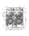
(プリンタの内部構成)
図15は、この発明にかかる実施の形態2のプリンタの内部構成を示す説明図である。図15において、この発明にかかる実施の形態2のプリンタは、第1のプリントユニット110および第2のプリントユニット120を収容するハウジング1501を備えている。図15においては、プリンタ1500を、図1におけるA−A線と同様の位置で切断した断面を示している。プリンタ1500は、鉛直方向に沿って重ね合わされた第1のプリントユニット110と第2のプリントユニット120との間に配置された、トレイ1502を備えている。
(Internal configuration of printer)
FIG. 15 is an explanatory diagram showing the internal configuration of the printer according to the second embodiment of the present invention. 15, the printer according to the second embodiment of the present invention includes a
プリンタ1500においては、トレイ1502のように有体物が設けられているものに限らない。プリンタ1500は、第1のプリントユニット110と第2のプリントユニット120との間に、トレイ1502のような部材を設けず、記録媒体を折り曲げることなく収容するために十分な空間が確保されていればよい。具体的には、たとえば、ハウジング1501内における第1のプリントユニット110と第2のプリントユニット120との位置関係を調整することによって、第1のプリントユニット110と第2のプリントユニット120との間に、「記録媒体を折り曲げることなく収容するために十分な空間」を確保することができる。
The
トレイ1502は、トレイ1502において第1の排出口205側と同じ側(図15における紙面左側)に開口1502aを備えている。開口1502aは、第1の排出口205の位置よりも、鉛直方向上側に設けられている。ハウジング1501内には、第1の排出口205と開口1502aと挿入口209と、を連通する反転経路1510が設けられている。
The
反転経路1510は、第1の排出口205と開口1502aとを連通する経路1511と、開口1502aと挿入口209とを連通する経路1512と、第1の排出口205と挿入口209とを連通する経路1513と、によって構成されている。これにより、ハウジング1501内には、第1の排出口205から開口1502aおよびトレイ1502内の空間を経由して挿入口209に至る経路(すなわち経路1511および経路1512)と、第1の排出口205から直接挿入口209に至る経路(すなわち経路1513)と、が形成されている。
The
反転経路1510において、第1の排出口205から開口1502aおよびトレイ150内の空間を経由して挿入口209に至る経路と、第1の排出口205から直接挿入口209に至る経路と、の分岐位置には、振り分け部を実現するフラップ状部材226が設けられている。フラップ状部材226の位置は、固定された一端を支点として揺動することにより、第1の排出口205と開口1502aとを連通する第1の位置と、第1の排出口205と挿入口209とを連通する第2の位置と、に自在に切り替えることができる。
In the
フラップ状部材226は、第2の位置に位置付けられている場合に第1のプリントユニット110から排出される記録媒体を鉛直方向上側に振り分け、第1の位置に位置付けられている場合に当該記録媒体を側方すなわちトレイ150内の空間に振り分ける。また、フラップ状部材226は、トレイ150内の空間に搬送された記録媒体を鉛直方向に沿って挿入口229に搬送する。
The flap-shaped
経路1513において、挿入口209の近傍には、経路1513中を搬送される記録媒体の位置をガイドするガイド部材(図示を省略する)が設けられている。このガイド部材は、たとえば、経路1513において、挿入口209の近傍において、第1のプリントユニット110あるいはトレイ150内の空間から搬送される記録媒体の先端を、第2のプリントユニット120側に向けるように湾曲した形状をなす部材によって実現することができる。実施の形態2においては、経路1513や経路1513に設けられたガイド部材によって、この発明にかかる案内部を実現することができる。
In the
また、反転経路1510において、記録媒体を開口1502aへ誘導する経路1511と、開口1502aを介してトレイ1502内の空間から排出される記録媒体を挿入口209を介して経路1512へ誘導する経路1511と、が分岐する位置の近傍であって、当該分岐する位置よりもトレイ1502側には、搬送ローラ対1520が設けられている。この実施の形態2においては、搬送ローラ対1520によって、この発明にかかる搬送部を実現することができる。
Further, in the
搬送ローラ対1520を構成する一対のローラ1520a、1520bのうちの一方のローラ1520aには、当該一方のローラ1520aを駆動するためのモータなどの駆動源や、当該駆動源が発生させた駆動力を一方のローラ1520aに伝達する動力伝達機構などが連結されている。
One
一方のローラ1520aを駆動するためのモータは正方向および逆方向のいずれの方向にも回転可能であり、これにより一方のローラ1520aは当該モータの回転方向に応じた方向に回転する。そして、これにより一方のローラ1520aは、第1の排出口205から排出された記録媒体をトレイ1502内の空間に搬送する方向(以下、適宜「第1の回転方向」という)と、トレイ1502内の空間から当該空間の外方に向けて記録媒体を搬送する方向(以下、適宜「第2の回転方向」という)と、のいずれの方向にも回転することができる。
The motor for driving one
この実施の形態2においては、切替部材220、フラップ状部材226、トレイ1502、経路1511、1512、1513および搬送ローラ対1520などによって、この発明にかかる搬送ユニットを実現することができる。また、この実施の形態2において、プリンタ1500のハウジング1501は、この発明にかかる搬送ユニットのハウジングを実現する。
In the second embodiment, the transfer unit according to the present invention can be realized by the switching
(プリンタ1500がおこなう記録動作)
プリンタ1500は、片面記録にかかる記録動作、両面記録にかかる記録動作および特殊色を重ねる記録動作をおこなうことができる。片面記録に際しては、上述したプリンタ100と同様の記録動作をおこなう。
(Recording operation performed by the printer 1500)
The
(両面記録)
両面記録にかかる記録動作に際して、プリンタ1500は、外部装置300から受信した両面記録指示に基づいて、第1のプリントユニット110においてフラップ状部材226を第1の位置に位置付け、第2のプリントユニット120において切替部材220を切断紙用の位置に位置付ける。
(Double-sided recording)
In the recording operation for the double-sided recording, the
そして、記録媒体の片面に対してすべての色の記録動作をおこない、片面に記録動作がおこなわれた記録媒体の記録面(おもて面)にオーバーコート層を設けた後、オーバーコート層を設けた記録媒体が、第1の保持部201から第1の排出口205へ向かって移動する方向に、第1の搬送経路206に設けられた搬送用のローラ対を回転させる。その後、オーバーコート層を設けた記録媒体を所定の位置まで引き出した状態で、第1のカッタ機構214により、片面(おもて面)に記録動作をおこなった記録媒体の記録部両端を切断する。
Then, the recording operation of all colors is performed on one side of the recording medium, and the overcoat layer is provided on the recording surface (front surface) of the recording medium on which the recording operation is performed on one side. The conveyance roller pair provided in the
つぎに、片面(おもて面)に記録動作がおこなわれた単票状の記録媒体を、第1の排出口205および開口1502a、すなわち経路1511を介してトレイ1502内の空間に搬送する。具体的に、プリンタ1500においては、フラップ状部材226が第1の位置に位置付けられているため、第1の排出口205側から開口1502a側へ向かって搬送される記録媒体は、先端がフラップ状部材226に突き当たると、当該フラップ状部材226に沿って開口1502a側へ屈曲する。この状態で、さらに第1の搬送経路206に設けられた搬送用のローラ対を回転させることにより、片面(おもて面)に記録動作がおこなわれた単票状の記録媒体を、当該記録媒体の先端側から、トレイ1502内の空間に搬送することができる。
Next, the single-sheet recording medium on which the recording operation is performed on one side (front side) is conveyed to the space in the
プリンタ1500は、第1のカッタ機構214によって切断された記録媒体の後端が、第1の位置に位置付けられたフラップ状部材226の先端位置を通過するまで、搬送ローラ対1520が備える一方のローラ1520aを正方向に回転させる。一方のローラ1520aを正方向に回転させることによって搬送される記録媒体は、開口1502aを介して、先端からトレイ1502内の空間に搬送される。
The
その後、プリンタ1500は、フラップ状部材226を第2の位置に位置付け、一方のローラ1520aを逆方向に回転させる。これにより、片面(おもて面)に記録動作がおこなわれ、先端からトレイ1502内の空間に搬送された単票状の記録媒体は、開口1502aを介してトレイ1502内の空間から外方へ搬送され、挿入口209へ向かって搬送される。
Thereafter, the
このとき、フラップ状部材226が第2の位置に位置付けられているため、トレイ1502内の空間から外方へ搬送される記録媒体は、先端がフラップ状部材226に突き当たると、当該フラップ状部材226に沿って挿入口209側へ屈曲する。この状態で、さらに搬送ローラ対1520が備える一方のローラ1520aを回転させることにより、片面(おもて面)に記録動作がおこなわれた単票状の記録媒体を、当該記録媒体の後端側から、挿入口209を介して第2のプリントユニット120に搬送することができる。
At this time, since the flap-shaped
先端からトレイ1502内の空間に搬送された記録媒体を、後端から第2のプリントユニット120に搬送することにより、当該記録媒体において、第1のサーマルヘッド203aに対向する面と、第2のサーマルヘッド204aに対向する面とを反転させることができる。
The recording medium conveyed from the front end to the space in the
第2のプリントユニット120は、上述したプリンタ100と同様に、挿入口209から挿入された記録媒体を検出すると、搬送用のローラ対を正方向に回転させ、外部装置300から受信した裏面用の記録指示に基づいて、上記の片面記録に際しての記録動作と同様の記録動作をおこなう。記録媒体において、第1のサーマルヘッド203aに対向する面と、第2のサーマルヘッド204aに対向する面とが反転されているため、第2のプリントユニット120において片面記録と同様の記録動作をおこなうことで、当該記録媒体の両面に記録することができる。
Similar to the
両面記録において、上記のように、第1のプリントユニット110における記録動作に際して、記録対象とする記録媒体が当該記録媒体の先端の余白を残して切断されている場合、第2のプリントユニット120は、両面記録にかかる記録動作に際して、当該記録媒体の先端の余白を第2のカッタ機構217によって切断する。
In double-sided recording, as described above, when the recording medium to be recorded is cut leaving a margin at the tip of the recording medium during the recording operation in the
その後、両面記録にかかる第2のプリントユニット120における記録動作に際しては、記録対象とする記録媒体の後端の余白を切断し、当該記録媒体を排出口141からプリンタの外へ排出する。このようにして、記録媒体に対する両面記録をおこなうことができる。
Thereafter, in the recording operation in the
(特殊色を重ねる記録動作)
プリンタ1500において、片面記録がおこなわれた記録媒体の記録面に対して特殊色を重ねる記録動作をおこなう場合は、第1の搬送ユニット130は、第1のプリントユニット110による記録動作が完了するまでに、フラップ状部材226を第2の位置に位置付ける。これにより、第1のプリントユニット110において片面記録をおこなった記録媒体は、先端がフラップ状部材226に突き当たると、当該フラップ状部材226に沿って挿入口209側へ屈曲する。
(Recording operation to overlay special colors)
When the
この状態で、さらに搬送ローラ対1520が備える一方のローラ1520aを回転させることにより、片面(おもて面)に記録動作がおこなわれた単票状の記録媒体は、当該記録媒体の後端側から、挿入口209を介して第2のプリントユニット120に搬送される。このように、先端から搬送経路1511中に搬送された記録媒体を、先端から第2のプリントユニット120に搬送することにより、当該記録媒体において、第1のサーマルヘッド203aに対向する面と、第2のサーマルヘッド204aに対向する面とを同じくしたままとすることができる。
In this state, by further rotating one
すなわち、第1の記録部203の記録位置に対向していた記録面と同じ面を第2の記録部204の記録位置に対して対向させた状態で、第2のプリントユニット120に搬送することができる。これにより、第2のプリントユニット120において片面記録と同様の記録動作をおこなうことで、片面(おもて面)に記録動作がおこなわれた単票状の記録媒体の記録面に対して特殊色を重ねる記録動作をおこなうことができる。
That is, the recording surface can be transported to the
以上説明したように、この発明にかかる搬送ユニットを備えた実施の形態2のプリンタ1500は、トレイ1502内の空間が、第1のプリントユニット110と第2のプリントユニット120との間に設けられていることを特徴としている。
As described above, in the
この発明にかかる実施の形態2のプリンタ1500によれば、第1のプリントユニット110による記録動作がおこなわれた記録媒体を、経路1512、1513を経由させることによって反転してから第2のプリントユニット120に搬送し、反転しない場合には経路1511を経由させることによって直接第2のプリントユニット120に搬送することができる。これにより、プリンタ1500は、記録媒体の表裏を反転させるための経路を第1のプリントユニット110と第2のプリントユニット120との間に収めることができる。
According to the
そして、これにより、プリンタ1500によれば、第1のプリントユニット110や第2のプリントユニット120の前面に反転経路(上述した実施の形態1のプリンタ100における反転経路224を参照)などの反転にかかる機構を確保する構成のプリンタ100などと比較して、プリンタ1500(プリントシステム)の大型化を抑制するとともに、開発設計や製造にコストをかけることなく、両面記録にかかるスループットの向上を図ることができる。また、プリンタ1500の正面側に反転にかかる機構を設ける場合と比較して、プリンタ1500の美観向上を図る効果が期待できる。
As a result, according to the
また、この発明にかかる実施の形態2のプリンタ1500によれば、記録媒体の表裏を反転させるための経路やトレイ1502を第1のプリントユニット110と第2のプリントユニット120との間に収める構成とすることにより、上述した実施の形態1のプリンタ100における搬送ローラ対225と比較して、搬送ローラ対1520を第2のプリントユニット120に近い位置に配置することができる。
In addition, according to the
これにより、第1のプリントユニット110から第2のプリントユニット120までの距離を短くすることができ、記録媒体の表裏を反転させるための経路やトレイ1502を第1のプリントユニット110と第2のプリントユニット120との間に収めない場合と比較して、第1のプリントユニット110において記録動作がおこなわれた記録媒体を、第2のプリントユニット120に搬送するために要するローラの数を少なくすることができる。これによって、開発設計や製造にコストをかけることなく、両面記録にかかるスループットの向上を図ることができる。
Accordingly, the distance from the
また、この発明にかかる実施の形態2のプリンタ1500によれば、記録媒体の表裏を反転させるための経路やトレイ1502を第1のプリントユニット110と第2のプリントユニット120との間に収める構成とすることにより、第1のプリントユニット110および第2のプリントユニット120をそれぞれ独立して構成することができる。このように、第1のプリントユニット110および第2のプリントユニット120を独立して構成可能とすることにより、第1のプリントユニット110および第2のプリントユニット120の共通化をおこないやすくすることができる。
In addition, according to the
具体的には、上述したように、第1のプリントユニット110と第2のプリントユニット120とをそれぞれ独立した部品とみなし、これらのプリントユニット110、120を鉛直方向に重ね合わせることによってプリンタ1500を実現することができる。これにより、プリンタ1500によれば、開発設計や製造にコストをかけることなく、両面記録にかかるスループットの向上を図ることができる。
Specifically, as described above, the
また、この発明にかかる実施の形態2のプリンタ1500によれば、反転にかかる機構(具体的には、トレイ1502、経路1511、経路1512、搬送ローラ対1520など)を設けない態様で利用する場合にも、反転にかかる機構を備えた態様(すなわち、図15に示す態様)のプリンタ1500における各部との共通化をおこないやすい。具体的に、図15に示したプリンタ1500からトレイ1502、経路1511、経路1512、搬送ローラ対1520などを取り外しただけの構成で、反転にかかる機構を設けない態様で利用することができる。これにより、プリンタ1500(プリントシステム)の大型化を抑制するとともに、開発設計や製造にコストをかけることなく、両面記録にかかるスループットの向上を図ることができる。
Further, according to the
また、この発明にかかる実施の形態2のプリンタ1500は、振り分け部を実現するフラップ状部材226が、第1のプリントユニット110から排出される記録媒体を鉛直方向上側に振り分けることにより第2のプリントユニット120に搬送し、当該記録媒体を鉛直方向に交差する方向(たとえば側方)に振り分けることによりトレイ1502内の空間に搬送し、さらに、当該空間に搬送された記録媒体を鉛直方向に沿って挿入口209に搬送することを特徴としている。
Further, in the
この発明にかかる実施の形態2のプリンタ1500によれば、第1のプリントユニット110と第2のプリントユニット120との間にトレイ1502(すなわち記録媒体を収容する空間)を設けた場合にも、第1のプリントユニット110から排出される記録媒体の振り分け、および、搬送ローラ対1520から案内経路1510への記録媒体の搬送をプリンタ1500における正面においておこなうことができ、当該記録媒体の反転を、第1のプリントユニット110および第2のプリントユニット120の間においておこなうことができる。これにより、プリンタ1500(プリントシステム)の大型化を抑制するとともに、開発設計や製造にコストをかけることなく、両面記録にかかるスループットの向上を図ることができる。
According to the
これにより、鉛直方向に沿って重ねた第1のプリントユニット110と第2のプリントユニット120とを備えるプリンタ100(プリントシステム)の大型化を抑制するとともに、開発設計や製造にコストをかけることなく、両面記録にかかるスループットの向上を図ることができる。
This suppresses an increase in the size of the printer 100 (print system) including the
また、この発明にかかる実施の形態2のプリンタ1500によれば、第1のプリントユニット110および第2のプリントユニット120の正面に、搬送ユニット(切替部材220、フラップ状部材226、トレイ1502、経路1511、1512、1513および搬送ローラ対1520など)を設けることにより、たとえば、表裏反転のために記録媒体が搬送ユニット130、140においてジャムを発生させた場合などにおいて、当該ジャムの解消作業を容易かつ確実におこなうことができる。
Further, according to the
なお、上述した実施の形態1においては、それぞれ独立して記録動作をおこなうことができるプリントユニット110、120に、独立した搬送ユニット130、140をそれぞれ取り付けることによって構成されたプリンタ100への適用例を示したが、これに限るものではない。プリントユニット110、120の構成および機能と、搬送ユニット130、140の構成および機能とを、単一のハウジング内に収容して一体に構成されたプリンタによってこの発明にかかるプリンタを実現してもよい。
In the first embodiment described above, an example of application to the
このようなプリンタは、具体的には、巻回された長尺状の記録媒体を保持する保持部と、保持部から引き出した記録媒体に対する記録動作をおこなう記録部と、記録部によって記録動作がおこなわれた長尺状の記録媒体を切断するカッタ部と、を備えたプリントユニットと、カッタ部において切断された記録媒体を、プリントユニットに重ねられた当該プリントユニットと同一の構成をなす別のプリントユニット側または当該別のプリントユニットとは反対側に振り分ける振り分け部と、振り分け部によって別のプリントユニット側に振り分けられた記録媒体が、当該別のプリントユニットが保持する別の記録媒体を引き出す位置に、当該別の記録媒体の引き出し方向と同一方向に沿って供給されるように案内する案内部と、振り分け部によって別のプリントユニットとは反対側に振り分けられた記録媒体を、当該記録媒体の後端が振り分け部を通過するまで収容し、当該後端が振り分け部を通過すると、当該記録媒体を当該後端から案内部へ搬送する搬送部と、を備える。そして、このようなプリンタは、振り分け部が、搬送部によって搬送される記録媒体を別のプリントユニット側に振り分けることを特徴とする。 Specifically, such a printer has a holding unit that holds a wound long recording medium, a recording unit that performs a recording operation on the recording medium drawn from the holding unit, and a recording unit that performs a recording operation. A print unit including a cutter unit that cuts the long recording medium that has been performed, and another print unit side that has the same configuration as the print unit that is stacked on the print unit. The distribution unit that distributes to the opposite side of the other print unit, and the recording medium that is distributed to the other print unit by the distribution unit is located at a position where the other print medium held by the other print unit is pulled out. A guide unit that guides the feed along the same direction as the drawer direction of the The recording medium distributed to the side opposite to the other print unit is stored until the rear end of the recording medium passes through the distribution unit, and when the rear end passes through the distribution unit, the recording medium is removed from the rear end. And a transport unit that transports to the guide unit. Such a printer is characterized in that the distribution unit distributes the recording medium conveyed by the conveyance unit to another print unit side.
このようなプリンタによれば、上述した実施の形態1と同様に、開発設計や製造にコストをかけることなく、利用者ごとの用途に応じた記録動作をおこなうことができる自由度の高いプリンタを提供することができる。 According to such a printer, as in the first embodiment described above, a printer with a high degree of freedom capable of performing a recording operation according to the use for each user without incurring development design and manufacturing costs. Can be provided.
以上のように、この発明にかかる搬送ユニットおよびプリンタは、記録媒体の両面への記録が可能なプリンタおよび当該プリンタに用いられる搬送ユニットに有用であり、特に、記録媒体の片面への記録と両面への記録とが要求されるプリンタおよび当該プリンタに用いられる搬送ユニットに適している。 As described above, the transport unit and the printer according to the present invention are useful for a printer capable of recording on both sides of a recording medium and a transport unit used in the printer, and particularly for recording on both sides of a recording medium and both sides. This is suitable for a printer that is required to perform recording on a printer and a transport unit used in the printer.
100 プリンタ
110 第1のプリントユニット
120 第2のプリントユニット
130 第1の搬送ユニット
140 第2の搬送ユニット
150 トレイ
201 第1の保持部
202 第2の保持部
203 第1の記録部
203a サーマルヘッド
203b プラテン
204 第2の記録部
204a サーマルヘッド
204b プラテン
214 第1のカッタ機構
217 第2のカッタ機構
220 切替部材
221 第1の開口
222 第2の開口
223 第3の開口
225 搬送ローラ対
226 振り分け部(フラップ状部材)
227 第4の開口
228 第5の開口
229 案内経路
230 ガイド部材
1500 プリンタ
1501 ハウジング
1502 トレイ
1502a 開口
1511、1512、1513 経路
1520 搬送ローラ対
1520a 一方のローラ
DESCRIPTION OF
227
Claims (10)
前記プリンタから排出される記録媒体を、前記プリンタに重ねられた当該プリンタと同一の構成をなす別のプリンタ側または当該別のプリンタ側とは異なる位置に振り分ける振り分け部と、
前記振り分け部によって前記別のプリンタ側に振り分けられた記録媒体が、当該別のプリンタが保持する別の記録媒体を引き出す位置に、当該別の記録媒体の引き出し方向と同一方向に沿って供給されるように案内する案内部と、
前記振り分け部によって前記別のプリンタ側とは異なる位置に振り分けられた記録媒体を、当該記録媒体の後端が前記振り分け部を通過するまで収容し、当該後端が前記振り分け部を通過すると、当該記録媒体を当該後端から前記案内部へ搬送する搬送部と、
を備え、
前記振り分け部は、前記搬送部によって搬送される記録媒体を前記別のプリンタ側に振り分けることを特徴とする搬送ユニット。 A holding unit that holds the wound long recording medium and a recording unit that performs a recording operation on the recording medium drawn from the holding unit, and cuts the long recording medium on which the recording operation has been performed. A transport unit provided in the printer for discharging
A distribution unit that distributes the recording medium discharged from the printer to a position different from the other printer side or another printer side having the same configuration as the printer stacked on the printer;
The recording medium sorted by the sorting unit to the other printer side is supplied to the position where the other recording medium held by the other printer is pulled out along the same direction as the direction of drawing out the other recording medium. And a guidance section that guides
The recording medium distributed by the distribution unit to a position different from the other printer side is accommodated until the rear end of the recording medium passes through the distribution unit, and when the rear end passes through the distribution unit, A transport unit for transporting the recording medium from the rear end to the guide unit;
With
The distribution unit distributes the recording medium conveyed by the conveyance unit to the other printer side.
前記ハウジングは、前記別のプリンタから排出される記録媒体を当該ハウジングの外に排出する排出部を備えたことを特徴とする請求項5または7に記載の搬送ユニット。 A housing for housing the sorting unit, the guide unit, and the transport unit;
The transport unit according to claim 5, wherein the housing includes a discharge unit that discharges a recording medium discharged from the another printer to the outside of the housing.
前記カッタ部において切断された記録媒体を、前記プリントユニットに重ねられた当該プリントユニットと同一の構成をなす別のプリントユニット側または当該別のプリントユニット側とは異なる位置に振り分ける振り分け部と、
前記振り分け部によって前記別のプリントユニット側に振り分けられた記録媒体が、当該別のプリントユニットが保持する別の記録媒体を引き出す位置に、当該別の記録媒体の引き出し方向と同一方向に沿って供給されるように案内する案内部と、
前記振り分け部によって前記別のプリントユニット側とは異なる位置に振り分けられた記録媒体を、当該記録媒体の後端が前記振り分け部を通過するまで収容し、当該後端が前記振り分け部を通過すると、当該記録媒体を当該後端から前記案内部へ搬送する搬送部と、
を備え、
前記振り分け部は、前記搬送部によって搬送される記録媒体を前記別のプリントユニット側に振り分けることを特徴とするプリンタ。 A holding unit that holds a wound long recording medium, a recording unit that performs a recording operation on the recording medium drawn from the holding unit, and a long recording medium on which the recording operation is performed by the recording unit A cutting unit, and a printing unit comprising:
A distribution unit that distributes the recording medium cut in the cutter unit to another print unit side having the same configuration as the print unit overlaid on the print unit or to a position different from the other print unit side;
The recording medium distributed to the other print unit by the distribution unit is supplied to a position where the other recording medium held by the other print unit is pulled out along the same direction as the other recording medium pulling direction. And a guidance section that guides
The recording medium distributed by the distribution unit to a position different from the other print unit side is accommodated until the rear end of the recording medium passes through the distribution unit, and when the rear end passes through the distribution unit, A transport unit for transporting the recording medium from the rear end to the guide unit;
With
The printer according to claim 1, wherein the distribution unit distributes the recording medium conveyed by the conveyance unit to the other print unit.
Priority Applications (5)
| Application Number | Priority Date | Filing Date | Title |
|---|---|---|---|
| JP2015135687A JP6502770B2 (en) | 2015-07-06 | 2015-07-06 | Transport unit and printer |
| PCT/JP2016/066083 WO2017006649A1 (en) | 2015-07-06 | 2016-05-31 | Conveyance unit and printer |
| CN201680039773.8A CN107735262B (en) | 2015-07-06 | 2016-05-31 | Supply unit and printer |
| US15/742,340 US10369810B2 (en) | 2015-07-06 | 2016-05-31 | Feeding unit and printer |
| EP16821120.9A EP3321090A4 (en) | 2015-07-06 | 2016-05-31 | Conveyance unit and printer |
Applications Claiming Priority (1)
| Application Number | Priority Date | Filing Date | Title |
|---|---|---|---|
| JP2015135687A JP6502770B2 (en) | 2015-07-06 | 2015-07-06 | Transport unit and printer |
Publications (2)
| Publication Number | Publication Date |
|---|---|
| JP2017014008A true JP2017014008A (en) | 2017-01-19 |
| JP6502770B2 JP6502770B2 (en) | 2019-04-17 |
Family
ID=57686185
Family Applications (1)
| Application Number | Title | Priority Date | Filing Date |
|---|---|---|---|
| JP2015135687A Active JP6502770B2 (en) | 2015-07-06 | 2015-07-06 | Transport unit and printer |
Country Status (5)
| Country | Link |
|---|---|
| US (1) | US10369810B2 (en) |
| EP (1) | EP3321090A4 (en) |
| JP (1) | JP6502770B2 (en) |
| CN (1) | CN107735262B (en) |
| WO (1) | WO2017006649A1 (en) |
Families Citing this family (3)
| Publication number | Priority date | Publication date | Assignee | Title |
|---|---|---|---|---|
| JP7155819B2 (en) * | 2018-09-28 | 2022-10-19 | ブラザー工業株式会社 | printer |
| CN110136364B (en) * | 2019-04-10 | 2021-04-30 | 维融科技股份有限公司 | Control method of self-service driver license issuing machine |
| WO2024039876A1 (en) * | 2022-08-18 | 2024-02-22 | Kodak Alaris Inc. | Modular stacking thermal printers |
Citations (5)
| Publication number | Priority date | Publication date | Assignee | Title |
|---|---|---|---|---|
| JP2003305893A (en) * | 2002-04-16 | 2003-10-28 | Canon Inc | Image recorder |
| JP2005028598A (en) * | 2003-07-07 | 2005-02-03 | Fuji Xerox Co Ltd | Print unit and printer |
| JP2011230386A (en) * | 2010-04-28 | 2011-11-17 | Canon Inc | Printer |
| JP2014028474A (en) * | 2012-07-31 | 2014-02-13 | Canon Inc | Printing method and sheet for printing used therefor |
| JP2014055042A (en) * | 2012-09-11 | 2014-03-27 | Citizen Holdings Co Ltd | Printer |
Family Cites Families (14)
| Publication number | Priority date | Publication date | Assignee | Title |
|---|---|---|---|---|
| JPS53149332A (en) * | 1977-06-01 | 1978-12-26 | Oriental Photo Ind Co Ltd | Sheettshaped photographic paper guiding device |
| JP2721112B2 (en) | 1993-09-08 | 1998-03-04 | スター精密株式会社 | Paper transport device |
| JPH07237336A (en) * | 1994-01-10 | 1995-09-12 | Fujitsu Ltd | Both-sided printing device of continuous paper |
| JP3710225B2 (en) * | 1996-09-06 | 2005-10-26 | 富士写真フイルム株式会社 | Photosensitive material processing equipment |
| JPH11338116A (en) * | 1998-03-25 | 1999-12-10 | Fuji Photo Film Co Ltd | Photographic processing method and printer processor |
| DE19929322A1 (en) * | 1999-06-25 | 2000-12-28 | Eastman Kodak Co | Inkjet printer for making photo prints |
| US6390464B1 (en) * | 1999-09-20 | 2002-05-21 | Hernan Gutierrez | Media handling devices and media handling methods |
| JP3818368B2 (en) * | 2000-09-07 | 2006-09-06 | セイコーエプソン株式会社 | Duplex printing device |
| JP4399129B2 (en) | 2001-06-14 | 2010-01-13 | シャープ株式会社 | Image forming apparatus |
| EP1510342B1 (en) * | 2003-09-01 | 2007-03-28 | FUJIFILM Corporation | Inkjet head and inkjet recording apparatus |
| JP2011093256A (en) | 2009-10-30 | 2011-05-12 | Sinfonia Technology Co Ltd | Thermal printer |
| JP5509791B2 (en) | 2009-10-30 | 2014-06-04 | シンフォニアテクノロジー株式会社 | Thermal printer |
| JP4999962B2 (en) * | 2010-05-13 | 2012-08-15 | キヤノン株式会社 | Printing apparatus and printing method |
| CN103221217B (en) * | 2010-06-24 | 2015-01-28 | 惠普发展公司,有限责任合伙企业 | Web press and method of printing |
-
2015
- 2015-07-06 JP JP2015135687A patent/JP6502770B2/en active Active
-
2016
- 2016-05-31 EP EP16821120.9A patent/EP3321090A4/en not_active Withdrawn
- 2016-05-31 US US15/742,340 patent/US10369810B2/en active Active
- 2016-05-31 CN CN201680039773.8A patent/CN107735262B/en not_active Expired - Fee Related
- 2016-05-31 WO PCT/JP2016/066083 patent/WO2017006649A1/en active Application Filing
Patent Citations (5)
| Publication number | Priority date | Publication date | Assignee | Title |
|---|---|---|---|---|
| JP2003305893A (en) * | 2002-04-16 | 2003-10-28 | Canon Inc | Image recorder |
| JP2005028598A (en) * | 2003-07-07 | 2005-02-03 | Fuji Xerox Co Ltd | Print unit and printer |
| JP2011230386A (en) * | 2010-04-28 | 2011-11-17 | Canon Inc | Printer |
| JP2014028474A (en) * | 2012-07-31 | 2014-02-13 | Canon Inc | Printing method and sheet for printing used therefor |
| JP2014055042A (en) * | 2012-09-11 | 2014-03-27 | Citizen Holdings Co Ltd | Printer |
Also Published As
| Publication number | Publication date |
|---|---|
| EP3321090A4 (en) | 2019-03-20 |
| CN107735262B (en) | 2019-06-07 |
| US20180201030A1 (en) | 2018-07-19 |
| CN107735262A (en) | 2018-02-23 |
| EP3321090A1 (en) | 2018-05-16 |
| US10369810B2 (en) | 2019-08-06 |
| JP6502770B2 (en) | 2019-04-17 |
| WO2017006649A1 (en) | 2017-01-12 |
Similar Documents
| Publication | Publication Date | Title |
|---|---|---|
| US8827440B2 (en) | Printer | |
| JP6632451B2 (en) | Printer | |
| WO2017006649A1 (en) | Conveyance unit and printer | |
| JP5158029B2 (en) | Tape cassette | |
| JP6107317B2 (en) | Recording device, transport device | |
| US10632769B2 (en) | Printer | |
| JP6639715B1 (en) | Printer | |
| JP6052970B2 (en) | Printer | |
| JP4544108B2 (en) | Printing device | |
| JP4400383B2 (en) | Printer | |
| JP4848713B2 (en) | Printing device | |
| JP2006123279A (en) | Printer | |
| JP2015081185A (en) | Both-sided printer for card | |
| JP6524349B2 (en) | Thermal printer | |
| JP5959411B2 (en) | Printer | |
| JP2021030627A (en) | Printer and printing system | |
| JP2005271532A (en) | Printer and printing method | |
| JP2002160390A (en) | Line printer | |
| JP2005271452A (en) | Printer | |
| JP2005297428A (en) | Printer | |
| JP2007083658A (en) | Printer | |
| JP2005313473A (en) | Printer | |
| JP2005280061A (en) | Printer | |
| JP2000343802A (en) | Method and apparatus for recording | |
| JP2012200878A (en) | Printer |
Legal Events
| Date | Code | Title | Description |
|---|---|---|---|
| A621 | Written request for application examination |
Free format text: JAPANESE INTERMEDIATE CODE: A621 Effective date: 20180515 |
|
| TRDD | Decision of grant or rejection written | ||
| A01 | Written decision to grant a patent or to grant a registration (utility model) |
Free format text: JAPANESE INTERMEDIATE CODE: A01 Effective date: 20190305 |
|
| A61 | First payment of annual fees (during grant procedure) |
Free format text: JAPANESE INTERMEDIATE CODE: A61 Effective date: 20190322 |
|
| R150 | Certificate of patent or registration of utility model |
Ref document number: 6502770 Country of ref document: JP Free format text: JAPANESE INTERMEDIATE CODE: R150 |
|
| R250 | Receipt of annual fees |
Free format text: JAPANESE INTERMEDIATE CODE: R250 |
|
| R250 | Receipt of annual fees |
Free format text: JAPANESE INTERMEDIATE CODE: R250 |
|
| R250 | Receipt of annual fees |
Free format text: JAPANESE INTERMEDIATE CODE: R250 |