JP4399129B2 - Image forming apparatus - Google Patents
Image forming apparatus Download PDFInfo
- Publication number
- JP4399129B2 JP4399129B2 JP2001180534A JP2001180534A JP4399129B2 JP 4399129 B2 JP4399129 B2 JP 4399129B2 JP 2001180534 A JP2001180534 A JP 2001180534A JP 2001180534 A JP2001180534 A JP 2001180534A JP 4399129 B2 JP4399129 B2 JP 4399129B2
- Authority
- JP
- Japan
- Prior art keywords
- image
- image forming
- forming unit
- recording paper
- unit
- Prior art date
- Legal status (The legal status is an assumption and is not a legal conclusion. Google has not performed a legal analysis and makes no representation as to the accuracy of the status listed.)
- Expired - Fee Related
Links
- 230000015572 biosynthetic process Effects 0.000 claims description 75
- 238000000926 separation method Methods 0.000 claims description 10
- 230000002441 reversible effect Effects 0.000 claims description 7
- 238000000034 method Methods 0.000 description 82
- 230000008569 process Effects 0.000 description 38
- 238000010586 diagram Methods 0.000 description 14
- 238000010438 heat treatment Methods 0.000 description 10
- 230000001360 synchronised effect Effects 0.000 description 9
- 238000011144 upstream manufacturing Methods 0.000 description 6
- 238000013500 data storage Methods 0.000 description 4
- 230000008901 benefit Effects 0.000 description 3
- 230000000694 effects Effects 0.000 description 3
- 230000003287 optical effect Effects 0.000 description 3
- 230000008859 change Effects 0.000 description 2
- 238000001035 drying Methods 0.000 description 2
- 239000000843 powder Substances 0.000 description 2
- 238000003825 pressing Methods 0.000 description 2
- 239000000654 additive Substances 0.000 description 1
- 230000000996 additive effect Effects 0.000 description 1
- 230000000740 bleeding effect Effects 0.000 description 1
- 238000006243 chemical reaction Methods 0.000 description 1
- 239000003795 chemical substances by application Substances 0.000 description 1
- 239000003086 colorant Substances 0.000 description 1
- 238000001816 cooling Methods 0.000 description 1
- 238000001514 detection method Methods 0.000 description 1
- 230000006866 deterioration Effects 0.000 description 1
- 238000007599 discharging Methods 0.000 description 1
- 238000002845 discoloration Methods 0.000 description 1
- 230000006870 function Effects 0.000 description 1
- 239000011521 glass Substances 0.000 description 1
- 239000007788 liquid Substances 0.000 description 1
- 238000002156 mixing Methods 0.000 description 1
- 239000000049 pigment Substances 0.000 description 1
- 230000005855 radiation Effects 0.000 description 1
- 230000009467 reduction Effects 0.000 description 1
- 229920005989 resin Polymers 0.000 description 1
- 239000011347 resin Substances 0.000 description 1
- 230000003068 static effect Effects 0.000 description 1
- 229920005992 thermoplastic resin Polymers 0.000 description 1
Images


Classifications
-
- G—PHYSICS
- G03—PHOTOGRAPHY; CINEMATOGRAPHY; ANALOGOUS TECHNIQUES USING WAVES OTHER THAN OPTICAL WAVES; ELECTROGRAPHY; HOLOGRAPHY
- G03G—ELECTROGRAPHY; ELECTROPHOTOGRAPHY; MAGNETOGRAPHY
- G03G15/00—Apparatus for electrographic processes using a charge pattern
- G03G15/22—Apparatus for electrographic processes using a charge pattern involving the combination of more than one step according to groups G03G13/02 - G03G13/20
- G03G15/221—Machines other than electrographic copiers, e.g. electrophotographic cameras, electrostatic typewriters
-
- B—PERFORMING OPERATIONS; TRANSPORTING
- B41—PRINTING; LINING MACHINES; TYPEWRITERS; STAMPS
- B41J—TYPEWRITERS; SELECTIVE PRINTING MECHANISMS, i.e. MECHANISMS PRINTING OTHERWISE THAN FROM A FORME; CORRECTION OF TYPOGRAPHICAL ERRORS
- B41J3/00—Typewriters or selective printing or marking mechanisms characterised by the purpose for which they are constructed
- B41J3/54—Typewriters or selective printing or marking mechanisms characterised by the purpose for which they are constructed with two or more sets of type or printing elements
- B41J3/546—Combination of different types, e.g. using a thermal transfer head and an inkjet print head
-
- G—PHYSICS
- G03—PHOTOGRAPHY; CINEMATOGRAPHY; ANALOGOUS TECHNIQUES USING WAVES OTHER THAN OPTICAL WAVES; ELECTROGRAPHY; HOLOGRAPHY
- G03G—ELECTROGRAPHY; ELECTROPHOTOGRAPHY; MAGNETOGRAPHY
- G03G15/00—Apparatus for electrographic processes using a charge pattern
- G03G15/04—Apparatus for electrographic processes using a charge pattern for exposing, i.e. imagewise exposure by optically projecting the original image on a photoconductive recording material
- G03G15/04036—Details of illuminating systems, e.g. lamps, reflectors
- G03G15/04045—Details of illuminating systems, e.g. lamps, reflectors for exposing image information provided otherwise than by directly projecting the original image onto the photoconductive recording material, e.g. digital copiers
- G03G15/04072—Details of illuminating systems, e.g. lamps, reflectors for exposing image information provided otherwise than by directly projecting the original image onto the photoconductive recording material, e.g. digital copiers by laser
Description
【0001】
【発明の属する技術分野】
この発明は、電子写真方式等の現像剤方式によるモノクロ画像形成を行う画像形成部と、インクジェット方式等のインク方式によるカラー画像形成を行う画像形成部と、を併設した画像形成装置に関する。
【0002】
【従来の技術】
従来より、カラー画像を形成する画像形成方法として、電子写真方式等の現像剤を用いた画像形成方法と、インクジェット方式等のインクを用いた画像形成方法と、がある。このうち、電子写真方式では、現像剤を加熱及び加圧して用紙上に強制的に定着させるために高速化に適し、比較的安価な現像剤を使用するためにランニングコストが安価になるという利点がある反面、熱可塑性を有する樹脂粉末に顔料又は染料を混入させた現像剤を記録用紙に転写した後に加熱して定着させるために樹脂粉末の透明度の影響や定着時の高温化による色相の変化によって色の再現性が低いという欠点がある。一方、インクジェット方式では、透明性の高い液体インクを高温に加熱することなく画像を形成するものであるために色の再現性に優れているという利点がある反面、インクの乾燥に長時間を必要とするために高速化に適さず、比較的高価なインクを使用するためにランニングコストが高騰する欠点がある。
【0003】
また、一般に記録用紙上に形成されるカラー画像情報としては、フルカラー画像情報よりも、書類等の文字画像の一部に挿入される印章、イラスト及びグラフ等の単色又は複数色の部分カラー画像情報が多い。
【0004】
これらの画像形成方式毎の特性やカラー画像の使用状況を考慮して、従来の画像形成装置では、電子写真方式等の現像剤方式の画像形成を行なう画像形成部とインクジェット方式等のインク方式の画像形成を行なう画像形成部とを併設し、現像剤方式の画像形成部においてモノクロの画像形成を行なうとともにインク方式の画像形成部においてカラーの画像形成を行なうようにしたものが提案されている。
【0005】
例えば、特開平8−95463号公報には、電子写真方式の画像形成を行なった後にインクジェット方式の画像形成を行なう画像形成装置において、電子写真方式のみで画像形成を行なう場合、電子写真方式及びインクジェット方式の両方で画像形成を行なう場合、並びに、インクジェット方式のみで画像形成を行なう場合のそれぞれに応じて、記録用紙の搬送速度を変える手段、又は、記録用紙を冷却する手段を設け、電子写真方式の画像形成部に含まれる定着装置を通過した記録用紙の温度を常に一定の範囲内に保つようにした構成が開示されている。この構成により、インクジェット方式による画像形成時のインクの滲みによる画像の劣化を抑えることができるとされている。
【0006】
【発明が解決しようとする課題】
しかしながら、現像剤方式の画像形成部とインク方式の画像形成部とを併設した従来の画像形成装置では、現像剤方式の画像形成速度とインク方式の画像形成速度との違いを考慮しつつ、現像剤方式の画像形成部とインク方式の画像形成部とを経由する用紙搬送路を短縮して装置を十分に小型化できるようにしたものがなかった。
【0007】
即ち、一般的に現像剤方式とインク方式とで画像形成時における用紙搬送速度は一致しないため、上流側の画像形成部と下流側の画像形成部との間の距離が記録用紙の長さより短い場合、記録用紙の後端が上流側の画像形成部を通過する前に記録用紙の前端が下流側の画像形成部に達し、記録用紙に弛みを生じてジャムを発生したり、記録用紙が前後に引っ張られて破損する。
【0008】
また、上流側の画像形成部と下流側の画像形成部との間の距離が記録用紙の長さより短く、現像剤方式の画像形成部の下流側に配置したインク方式の画像形成部が用紙搬送方向に直交する方向である主走査方向に往復移動するインクヘッドを備えるとともに、インクヘッドが主走査方向に移動する間において記録用紙の搬送を停止する構成とした場合、上流側の現像剤方式の画像形成部において非画像形成時にも所定の高温に維持された定着部に対して記録用紙を一様な速度で通過させることができず、定着部における加熱及び加圧によって受ける影響度合いが不均一になり、均一な画像形成状態を得ることができない。
【0009】
これに対して、特開平10−10819号公報に開示されているように、電子写真方式の画像形成部の用紙搬送方向における下流側にインクジェット方式の画像形成部を配置し、電子写真方式の画像形成部に含まれる定着ロールとインクジェット方式の画像形成部に含まれるインクジェットヘッドとの間の搬送路長を記録用紙長よりも長くした場合には、用紙搬送路が長くなって装置の大型化を招く問題がある。
【0010】
また、現像剤方式の画像形成部とインク方式の画像形成部とを併設した従来の画像形成装置では、記録用紙の両面に画像を形成する場合について考慮されておらず、モノクロ画像、カラー画像、又は、モノクロ画像とカラー画像との混在画像のいずれかを、記録用紙の片面のみ、又は、両面に形成するそれぞれの場合において、画像形成速度を最速にできるように構成された最短の搬送経路に適合した状態で各画像形成部に画像データを供給することができず、画像の再現性が低下する問題があった。
【0011】
さらに、現像剤方式の画像形成部では一般に記録用紙上に現像剤画像を定着させるために記録用紙を加熱及び加圧する定着装置を備えているが、定着装置による加熱及び加圧によって記録用紙に変形を生じる。記録用紙の片面又は両面にモノクロ画像とカラー画像との両方が混在した画像を形成する場合には、加熱及び加圧により変形した後の記録用紙に対して画像形成が行われることになるが、画像情報のサイズの調整について考慮していない従来の画像形成装置では、記録用紙上におけるモノクロ画像とカラー画像との相対的なサイズが一致しなくなり、画像の再現性が低下する問題がある。
【0012】
この発明の目的は、モノクロ画像、カラー画像、又は、モノクロ画像とカラー画像との混在画像のいずれかを、記録用紙の片面のみ、又は、両面のそれぞれに形成するそれぞれの場合において、画像形成速度を最速にできるように構成された最短の搬送経路に適合した状態で各画像形成部に画像データを供給することができるとともに、少なくとも一方の画像形成部を通過する間に変形を生じた記録用紙上におけるモノクロ画像とカラー画像との相対的なサイズを正確に一致させることができ、画像の再現性を向上することができる画像形成装置を提供することにある。
【0013】
【課題を解決するための手段】
この発明は、上記の課題を解決するための手段として、以下の構成を備えている。
【0014】
(1)モノクロ画像情報に基づく電子写真方式の画像形成を行う第1の画像形成部と、カラー画像情報に基づくインクジェット方式の画像形成を行う第2の画像形成部と、を給紙部から排紙部に至る記録用紙の搬送経路中にこの順に配置し、前記搬送経路中を搬送される記録用紙の両面に画像を形成する画像形成装置において、
原稿の表裏面のそれぞれからの入力画像情報に対する画像処理を行う画像処理部と、
前記画像処理部で画像処理を施された表面画像情報及び裏面画像情報のそれぞれを記憶する表面画像記憶部及び裏面画像記憶部と、
を備え、
前記搬送経路中には、
前記排紙部側に、記録用紙の搬送方向を正方向、または逆方向に選択的に切り替えられる排紙搬送路が設けられているとともに、
前記排紙搬送路において逆方向に搬送している記録用紙が導かれ、この記録用紙を前記第1の画像形成部、および前記第2の画像形成部が画像を形成する搬送路へ、画像形成面を表裏反転して導く副搬送路が設けられ、
前記画像処理部は、
記録用紙の表面に対する画像形成時に、前記表面画像記憶部から読み出した表面画像情報について各色相値と所定の閾値との比較結果に基づいてモノクロ画像情報であるかカラー画像情報であるかの判別を行い、モノクロの表面画像情報を前記第1の画像形成部に供給するとともにカラーの表面画像情報を前記第2の画像形成部に供給し、
記録用紙の裏面に対する画像形成時に、前記裏面画像記憶部から読み出した裏面画像情報について各色相値と所定の閾値との比較結果に基づいてモノクロ画像情報であるかカラー画像情報であるかの判別を行い、モノクロの裏面画像情報を前記第1の画像形成部に供給するとともにカラーの裏面画像情報を前記第2の画像形成部に供給し、
前記第1の画像形成部は、
記録用紙の両面に画像を形成するとき、この記録用紙の一方の面に対する画像形成を行った後、他方の面に対する画像形成を行い、
前記第2の画像形成部は、
記録用紙の両面に画像を形成するとき、この記録用紙の前記他方の面に対する画像形成を行った後、前記一方の面に対する画像形成を行う、ことを特徴とする。
【0015】
この構成においては、モノクロ画像データに対する画像処理、及び、カラー画像データに対する画像処理が、同一の画像処理部で実行される。したがって、モノクロ画像データの記憶手段とカラー画像データの記憶手段とを個別に設ける必要がなく、画像処理部の構成が簡略化される。また、モノクロ画像データ及びカラー画像データが第1の画像形成部及び第2の画像形成部に対して個別のタイミングで出力される。したがって、第1の画像形成部における画像形成方式と第2の画像形成部における画像形成方式とが相違し、互いの画像形成処理時の動作タイミングが異なる場合にも、単一の画像処理部からそれぞれの画像形成部に対して適正なタイミングで画像データが供給される。
【0017】
また、色分解後の入力画像情報における各色相値を所定の閾値と比較して、入力画像情報がモノクロ画像情報であるかカラー画像情報であるかが判別される。したがって、入力画像情報が互いに異なる画像処理が施されるモノクロ画像情報であるかカラー画像情報であるかが正確且つ素早く判別され、画像処理動作が短時間化される。
【0018】
(2)前記画像処理部は、色分解後の入力画像情報における各色相値を所定の閾値と比較し、少なくとも1つの色相値が閾値以上である場合に、カラー画像情報であると判別し、色分解後の入力画像情報における各色相値の他の色相値との差が所定の閾値以下である時に、入力画像情報がモノクロ画像情報であると判断することを特徴とする。
【0019】
この構成においては、色分解後の入力画像情報における少なくとも1つの色相値が所定の閾値以上である場合に入力画像情報がカラー画像情報であると判断される。したがって、色相の鮮やかなカラー画像情報についての判別時間が短縮される。
【0021】
また、色分解後の入力画像情報における各色相値間の差が少ない場合に入力画像情報がモノクロ画像情報であると判断される。したがって、入力画像情報がモノクロ画像情報であるかカラー画像情報であるかの判別時間が短縮される。
【0024】
(3)前記画像処理部は、記録用紙の搬送経路における第1の画像形成部の直前に配置された搬送部材の駆動タイミングに合致したタイミングでモノクロ画像情報を第1の画像形成部に出力し、
記録用紙の搬送経路における第2の画像形成部の直前に配置された搬送部材の駆動タイミングに合致したタイミングでカラー画像情報を第2の画像形成部に出力することを特徴とする。
【0025】
この構成においては、第1の画像形成部の直前に配置された搬送部材によって記録用紙が第1の画像形成部内に導かれるタイミングに合わせてモノクロ画像情報が第1の画像形成部に供給される。したがって、第1の画像形成部に既存の搬送部材の駆動タイミングに基づいて、第1の画像形成部における記録用紙に対する画像形成処理に合致したタイミングで第1の画像形成部に対してモノクロ画像情報が供給される。また、第2の画像形成部の直前に配置された搬送部材によって記録用紙が第2の画像形成部内に導かれるタイミングに合わせてカラー画像情報が第2の画像形成部に供給される。したがって、第2の画像形成部に既存の搬送部材の駆動タイミングに基づいて、第2の画像形成部における記録用紙に対する画像形成処理に合致したタイミングで第2の画像形成部に対してカラー画像情報が供給される。
【0040】
【発明の実施の形態】
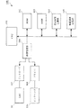
以下に、この発明の実施形態に係る画像形成装置としてディジタル複写機を例にあげて説明する。図1は、この発明の実施形態に係るディジタル複写機の構成を示す概略図である。また、図2は、上記ディジタル複写機のプリンタ部における第2画像形成部の近傍の構成を示す図である。ディジタル複写機1は、上部にスキャナ部1A、中間部にプリンタ部1B、下部に給紙部1Cを配置して、略コの字型形状に構成されている。
【0041】
スキャナ部1Aは、ディジタル複写機1の上面に露出する透明硬質ガラス体の原稿台15を備え、この原稿台15の下方に光源ランプ11、ミラー12a〜12c、レンズ13及び光電変換素子(以下、CCDと言う。)14を含むスキャナ光学系10を備えている。露光ランプ11は、ミラー12aとともに原稿台15の下面に平行に往復移動し、原稿台15の上面に載置された原稿の画像面を露光する。ミラー12b,12cは、光源ランプ11及びミラー12aの1/2の速度で原稿台15の下面に平行に往復移動し、光源ランプ11から照射された光の原稿の画像面における反射光を光路長を一定にしてレンズ13に配光する。レンズ13は、原稿の画像面における反射光をCCD14の受光面に結像する。CCD14は、受光面における受光量に応じた受光信号を出力する。CCD14から出力された受光信号は、後述する画像処理部においてディジタルデータに変換された後に所定の画像処理を施されて画像データとしてプリンタ部1Bに供給される。
【0042】
なお、この例では、原稿台上に位置を固定して載置された原稿の画像を原稿台に平行に移動するスキャナ光学系によって読み取る原稿固定方式のスキャナ部について説明したが、原稿移動方式のみ、又は、原稿移動方式と原稿固定方式とを併用したスキャナ部を用いることもできる。
【0043】
プリンタ部1Bは、電子写真方式によるモノクロ画像形成を行う第1画像形成部20(この発明の第1の画像形成部)とインクジェット方式によるカラー画像形成を行う第2画像形成部50(この発明の第2の画像形成部)とを併設して構成されている。これによって、高速化に優れた電子写真方式とカラー画像の再現性に優れたインクジェット方式とのそれぞれの長所を生かした画像形成を可能にしている。
【0044】
第1画像形成部20は、感光体ドラム28の周囲に、帯電器29、レーザスキャンユニット(以下、LSUと言う。)30、現像ユニット31、転写器32等を感光体ドラム28の回転方向に沿ってこの順に配置し、さらに、主搬送路41における感光体ドラム28と転写器32との間の下流側に定着装置23を配置して構成されている。第1画像形成部20における画像形成時には、矢印方向に所定のプロセス速度で回転する感光体ドラム28の表面に対して、帯電器29から所定の電荷が均一に付与された後、LSU30から画像データによって変調されたレーザ光が照射される。これによって感光体ドラム28の表面には静電潜像が形成される。現像ユニット31は、静電潜像が形成された感光体ドラム28の表面に現像ローラ31aを介して現像剤を供給し、静電潜像を現像剤像に顕像化する。転写器32は、感光体ドラム28の表面に担持された現像剤像を記録用紙Pの表面に転写する。なお、転写工程を終了した感光体ドラム28の表面は、図示しないクリーナ及び除電器によって残留現像剤及び残留電荷の除去を受け、画像形成プロセスに繰り返し使用される。定着装置23は、図2に示すように、加熱ローラ23aと加圧ローラ23bとを所定の押圧力で圧接させ、この間を通過する記録用紙Pを加熱及び加圧し、記録用紙Pに転写されたトナー像を高温高圧下で押し潰すことにより、記録用紙P上に熱定着させる。
【0045】
第2画像形成部50は、プリンタ部1Bにおいて、主搬送路41の下流側に連続する排紙搬送路42に配置されている。第2画像形成部50は、図2に示すように、インクヘッド53a及びインクタンク53bを搭載したキャリッジ53をシャフト54を介して主走査方向に往復移動自在に支持し、排紙搬送路42を挟んでキャリッジ53に対向するプラテン55を備えている。また、排紙搬送路42中には、キャリッジ53及びプラテン55の対向位置を挟んで、この発明の第2の画像形成部の直前に配置された搬送部材である搬送ローラ51a,52aが正逆両方向に回転自在に支持されており、それぞれの上方に軸支されたスターローラ51b,52bとの間に記録用紙Pを挟持して搬送する。スターローラ51b,52bは、後述するスターローラ25bと同様に、第2画像形成部50においてインク画像が形成された記録用紙Pの画像形成面との接触面積を小さくして画像の滲みを防止するために用いられる。
【0046】
キャリッジ53は、プラテン55との間に記録用紙Pが停止している状態で主走査方向に移動し、この間に画像データに基づいて駆動されるインクヘッド53aの複数のノズルから選択的にインクが吐出される。キャリッジ53が主走査方向の1ライン分の移動を終了した時点で、搬送ローラ51a,52aの回転によって記録用紙Pがインクヘッド53aにおけるノズルの配置範囲分に相当する距離だけ搬送される。このインクヘッド53の駆動を伴うキャリッジ53の主走査方向の移動と記録用紙Pの間歇搬送とを繰り返すことにより、記録用紙Pの全面にインクによる画像が形成される。
【0047】
なお、プリンタ部1B内には、主搬送路41及び排紙搬送路42に加えて、副搬送路43が形成されており、主搬送路41と排紙搬送路42との間には、副搬送路43を開閉するフラッパ56が揺動自在に設けられている。
【0048】
給紙部1Cは、本体の一方の側面に装着された給紙トレイ16、複数枚の用紙を収納して本体に着脱自在にされた給紙カセット17、給紙トレイ16上に載置された記録用紙P及び給紙カセット17内に収納された記録用紙Pを一枚ずつ繰り出すピックアップローラ18a,18b、並びに、ピックアップローラ18bによって繰り出された記録用紙Pをプリンタ部1Bに給紙する給紙ローラ19を備えている。給紙部1Cには、給紙トレイ16及び給紙カセット17のそれぞれを主搬送路41の上流側に連絡する給紙搬送路44,45が形成されている。
【0049】
プリンタ部1B内において、主搬送路41内には、定着装置23を構成する加熱ローラ23a及び加圧ローラ23bに加えて、レジストローラ22が配置されている。レジストローラ22は、この発明の第1の画像形成部の直前に配置された搬送部材であり、感光体ドラム28の回転に先立って給紙部1Cから給紙された記録用紙Pを一旦停止させた後、感光体ドラム28の回転に同期して感光体ドラム28と転写器32との間に導く。即ち、レジストローラ22は、記録用紙Pが給紙部1Cから給紙された時点では回転を停止しており、感光体ドラム28と転写器32とが対向する位置において記録用紙Pの前端部が感光体ドラム28に担持されたトナー像の前端部に一致するタイミングで回転を開始する。
【0050】
ディジタル複写機1において、スキャナ部1Aと給紙部1Cとの間の空間には、プリンタ部1Bの一方の側面に装着された排紙トレイ39が配置されている。プリンタ部1B内に形成された排紙搬送路42は主搬送路41の下流側端部を排紙トレイに39に連通するものであり、排紙搬送路42の排紙トレイ39側の端部には排紙ローラ25aがスターローラ25bとともに設けられている。この排紙ローラ25aは、搬送ローラ51a,52aと同様に正逆両方向に回転自在にされており、搬送ローラ51a,52aとともに第1画像形成部20における両面画像形成機能の実現に使用される。
【0051】
即ち、第1画像形成部20において記録用紙Pの片面に画像を形成する片面画像形成モード時には、フラッパ56が図2中実線で示す状態に位置するとともに、搬送ローラ51a,52a及び排紙ローラ25aは図2中時計方向に正転し、定着装置23を通過した記録用紙Pは、排紙搬送路42を通過して排紙トレイ39上に排出される。これに対して、記録用紙Pの両面に画像を形成する両面画像形成モードにおける第1面画像形成時には、記録用紙Pの後端が搬送ローラ52aを通過した時点で、フラッパ56が図2中破線で示す状態に移動するとともに、搬送ローラ51a,52a及び排紙ローラ25aが図2中反時計方向に逆転し、記録用紙Pは副搬送路43内に導かれ、記録用紙Pの全面が副搬送路43内に移動した時点で、フラッパ56は図2中実線で示す状態に移動する。副搬送路43を通過した記録用紙Pは、主搬送路41の上流側を経由して表裏面を反転した状態で第1画像形成部20に導かれ、第2面に対する画像形成を受けた後、図2中時計方向に正転する搬送ローラ51a,52a及び排紙ローラ25aによって排紙トレイ39上に排出される。
【0052】
なお、以下の説明においては、搬送ローラ51aとスターローラ51bとを一体的に搬送ローラ51といい、搬送ローラ52aとスターローラ52bとを一体的に搬送ローラ52といい、排紙ローラ25aとスターローラ25bとを一体的に排紙ローラ25という。
【0053】
図3は、上記ディジタル複写機の制御部の構成を示す図である。ディジタル複写機1の制御部100は、ROM102及びRAM103を備えたCPU101に、表面画像記憶部104、裏面画像記憶部105及び画像処理部106を接続して構成されている。表面画像記憶部104及び裏面画像記憶部105のそれぞれは、スキャナ部1Aにおいて1枚の原稿の表面及び裏面のそれぞれから読みとられた表面画像データ及び裏面画像データのそれぞれを記憶する。
【0054】
画像処理部106は、表面画像記憶部104及び裏面画像記憶部105に記憶されている画像データに対して所定の画像処理を施す。この画像処理部106には、第1画像形成部20に設けられたLSU30のコントローラ107、及び、第2画像形成部50に設けられたインクヘッド53aのドライバ108が接続されている。画像処理部106は、所定の画像処理を施したモノクロ画像データを所定のタイミングでコントローラ107に供給するとともに、所定の画像処理を施したカラー画像データを所定のタイミングでドライバ108に供給する。
【0055】
図4は、上記ディジタル複写機の制御部の処理手順を示すフローチャートである。制御部100のCPU101は、電源が投入されると、イニシャライズ処理の後に、画像形成要求の入力を待機し(s1)、画像形成要求が入力されると、画像形成の対象となる原稿が片面原稿であるか両面原稿であるかの判別を行う(s2,s3)。CPU101は、片面原稿であると判定した場合には、スキャナ部1Aを介して原稿の画像を読み取り(s4)、読み取った画像データを表面画像記憶部104に格納した後(s5)、表面画像記憶部104に格納されている画像データに対して画像処理部106を介して所定の画像処理を施す(s6)。一方、画像形成の対象となる原稿が両面原稿である場合には、CPU101は、スキャナ部1Aを介して原稿の表面から読み取った画像データを表面画像記憶部104に格納するとともに原稿の裏面から読み取った画像データを裏面画像記憶部105に格納し(s7,s8)、表面画像記憶部104及び裏面画像記憶部105に格納されている画像データに対して画像処理部106を介して所定の画像処理を施す(s9)。
【0056】
次いで、CPU101は、表面画像記憶部104及び裏面画像記憶部105に格納されている画像データが、モノクロ画像データのみ、カラー画像データのみ、又は、モノクロ画像とカラー画像との混在画像データの何れであるかの判別を行う(s10〜s12)。CPU101は、モノクロ画像データのみが格納されている場合には第1画像形成部20における電子写真方式のモノクロ画像形成処理を実行し(s13)、カラー画像データのみが格納されている場合には第2画像形成部50におけるインクジェット方式のカラー画像形成処理を実行し(s14)、混在画像データが格納されている場合には第1画像形成部20及び第2画像形成部50における混在画像形成処理を実行する(s15)。CPU101は、上記s2〜s15の処理を画像形成要求に含まれる全ての原稿について繰り返し実行する(s16→s2)。
【0057】
ここで、モノクロ画像とカラー画像とが混在する混在原稿から読み取った混在画像データについては、画像処理部106は、従来と異なる手順で記憶部104,105に格納するとともに、コントローラ107及びドライバ108に供給する。即ち、従来の画像形成装置では、モノクロ画像データに対する画像処理を行う画像処理部とカラー画像データに対する画像処理を行う画像処理部とを個別に設けるとともに、混在画像データを原稿の表裏面のそれぞれについてモノクロ画像データとカラー画像データとに区別して所定の画像処理後に表面画像記憶部及び裏面画像記憶部に格納するようにしていた。
【0058】
これに対して、この発明の画像処理部106は、図5に示すように、原稿の表裏面のそれぞれから読み取られた混在画像データをモノクロ画像データとカラー画像データとに区別することなく、単一の画像処理部106で所定の画像処理を施した後に表面画像記憶部104及び裏面画像記憶部105に格納し、第1画像形成部20及び第2画像形成部50での画像形成時に表面画像記憶部104及び裏面画像記憶部105から読み出した画像データがモノクロ画像データであるかカラー画像データであるかを判別し、モノクロ画像データをLSU30のコントローラ107に供給するとともに、カラー画像データをインクヘッド53aのドライバ108に供給する。
【0059】
但し、第1画像形成部20におけるモノクロ画像形成処理と第2画像形成部50におけるカラー画像形成処理とが同時に行われることはないため、画像処理部106は、第1画像形成部20における電子写真方式のモノクロ画像形成が実行される時にモノクロ画像データと判別した画像データのみを第1画像形成部20に供給し、第2画像形成部50におけるカラー画像形成が実行される時にカラー画像データと判別した画像データのみを第2画像形成部50に供給する。
【0060】
このように、画像処理部106は混在画像データをモノクロ画像データとカラー画像データとに区別することなく記憶するため、表面画像記憶部104及び裏面画像記憶部105の記憶容量を削減することができるとともに、画像処理部106におけるモノクロ画像データの処理経路とカラー画像データの処理経路とが同一になり、画像処理部106の構成を簡略化することができる。
【0061】
この場合、画像処理部106からコントローラ107及びドライバ108に供給する際のモノクロ画像データ及びカラー画像データの判別処理は、正確かつ容易に行われることが望ましい。このため、画像処理部106は、一例として、図6のフローチャートに示す処理により、加法混色の三原色であるR(赤)、G(緑)、B(青)の各色相値に基づいて、モノクロ画像データであるかカラー画像データであるかを判別する。
【0062】
画像処理部106は、先ず、R,G,Bの各色相値と他の色相値との差が所定範囲内であるか否かを判別し(s21〜s23)、R,G,Bの各色相値間の差が所定範囲内である場合には、モノクロ画像データであると判断する(s23→s30)。これは、グレースケール中の画像において、R,G,Bの各色相値が略同一となることに基づく。
【0063】
R,G,Bの各色相値間のいずれかで所定範囲を超える差がある場合には、画像処理部106は、各色相値を所定の閾値と比較し(s24〜s26)、全ての色相値が所定の閾値を超える場合には、モノクロ画像データであると判断する(s26→s30)。これは、グレースケール中の画像において、R,G,Bの各色相値が全て高い値を示す場合があることに基づく。
【0064】
R,G,Bのいずれかが所定範囲を超えない場合には、画像処理部106は、各色相値を所定の閾値と比較し(s27〜s29)、全ての色相値が所定の閾値以下である場合には、モノクロ画像データであると判断する(s29→s30)。これは、グレースケール中の画像において、R,G,Bの各色相値が全て低い値を示す場合があることに基づく。上記s21〜s29の判別において、モノクロ画像データであると判断されなかった画像がカラー画像データであると判断される。
【0065】
以上の処理によって、モノクロ画像データであるかカラー画像データであるかを、正確かつ素早く判断することができる。
【0066】
次に、上記ディジタル複写機1における画像形成処理時の記録用紙の搬送状態、及び、画像データの処理状態について、モノクロ画像形成処理時、カラー画像形成処理時及び混在画像形成処理時のそれぞれの場合に分けて説明する。
【0067】
(1)モノクロ画像形成処理
第1画像形成部20における電子写真方式でモノクロ画像を形成するモノクロ画像形成処理時には、図7のフローチャートに示すように、CPU101は、記録用紙Pの片面に画像を形成する片面画像形成モードであるか、記録用紙Pの両面に画像を形成する両面画像形成モードであるかの判別を行ない(s101,s102)、片面画像形成モード時には、表面画像記憶部104に格納されている表面用モノクロ画像データを画像の前端部から順に読み出し、レジストローラ22の駆動タイミングに同期したタイミングで、画像処理部106を介してコントローラ107に供給する。これによって、第1画像形成部20において、感光体ドラム28の表面にLSU30によって静電潜像が形成され(s103)、現像ユニット31からの現像剤の供給によって静電潜像を現像剤像に顕像化し(s104)、給紙部1Cから給紙された記録用紙Pが図8(A)に示すように感光体ドラム28と転写器32との間を通過する間に、記録用紙Pに対して転写器32により現像剤像を転写する(s105)。
【0068】
次いで、定着装置23において記録用紙Pを加熱及び加圧することによって現像剤像を記録用紙P上に定着させ(s106)、フラッパ56を図2中実線で示す状態に位置させて主搬送路41と排紙搬送路42とを連通し(s107)、図8(B)に示すように記録用紙Pを第2画像形成部50に通過させ、図8(C)に示すようにモノクロ画像が形成された表面を下向きにしたFaceDown状態で記録用紙Pを排紙トレイ39上に排出する(s108)。
【0069】
両面画像形成モード時には、CPU101は、裏面画像記憶部105に記憶されている裏面用モノクロ画像データを画像の前端側から順に読み出し、レジストローラ22の駆動タイミングに同期したタイミングで第1画像形成部20に供給し(s109)、上記s104〜s107と同様の処理により、図9(A)に示すように第1画像形成部20において第1面に現像剤画像が形成された記録用紙Pを排紙搬送路42に導き(s110〜s113)、第2の画像形成部50を通過した記録用紙Pが排紙ローラ25にチャックされた状態で排紙ローラ25の回転を停止した後(s114)、フラッパ56を図2中破線で示す状態に位置させて排紙搬送路42と副搬送路43との間を開放し、図9(B)に示すように、搬送ローラ51,52及び排紙ローラ25を逆転させる(s115)。これによって、記録用紙Pを副搬送路43を経由して表裏面を反転した状態で再度主搬送路41に導く。
【0070】
この後、CPU101は、表面画像記憶部104に記憶されている表面用モノクロ画像データを画像の後端側から順に読み出し、レジストローラ22の駆動タイミングに同期したタイミングで第1画像形成部20に供給し(s116)、上記s104〜s108と同様の処理により、図9(C)に示すように第1画像形成部20において第1面に現像剤画像が形成された記録用紙Pを排紙搬送路42を経由してFaceDown状態で排紙トレイ39上に排出する(s117〜s121)。
【0071】
このように、モノクロ画像の両面画像形成モード時において、先に記録用紙Pの裏面に対する画像形成を行った後に、記録用紙Pの表面に対する画像形成を行うようにしているのは、複数枚の記録用紙Pの両面にページの連続した画像を形成する場合に、排紙トレイ39に排出された複数枚の記録用紙Pのページ順を並べ替える作業(丁合作業)を不要にするためである。また、裏面用モノクロ画像データを画像の前端側から順に読み出すとともに、表面用モノクロ画像データを画像の後端側から順に読み出すのは、主搬送路41を2回通過する間に記録用紙Pの表裏面を反転させるべく、裏面に対する画像形成終了後に記録用紙Pをスイッチバックさせて搬送する結果、裏面に対する画像形成時と表面に対する画像形成時とで記録用紙Pの搬送方向の前後が反転するためである。
【0072】
(2)カラー画像形成処理
第2画像形成部50におけるインクジェット方式でカラー画像を形成するカラー画像形成処理時には、図10のフローチャートに示すように、CPU101は、用紙Pの片面に画像を形成する片面画像形成モードであるか、用紙Pの両面に画像を形成する両面画像形成モードであるかの判別を行ない(s201,s202)、片面画像形成モード時には、表面画像記憶部104に格納されている表面用カラー画像データを画像の後端側から順に読み出す(s203)。一方、給紙部1Cから給紙された記録用紙Pを主搬送路41を経由して搬送し(s204)、フラッパ56を図2中実線で示す状態に位置させて記録用紙Pを排紙搬送路42に導き(s205)、図11(A)に示すように、排紙ローラ25が記録用紙Pをチャックしている状態で排紙ローラ25を一旦停止させる(s206)。
【0073】
この後、フラッパ56を図2中破線で示す状態に位置させて排紙搬送路42と副搬送路43との間を開放した状態で、図11(B)に示すように、記録用紙Pの後端が搬送ローラ52に達するまで排紙ローラ25を反転させて記録用紙Pを図11に示す矢印b方向に搬送した後(s207)、搬送ローラ52の駆動タイミングに同期したタイミング(記録用紙Pの後端と画像後端部のカラー画像データとが一致するタイミング)でインクヘッド53aのドライバ108に表面用カラー画像データを供給し、記録用紙Pの矢印b方向の搬送と第2画像形成部50におけるキャリッジ53及びインクヘッド53aの駆動とを調整して記録用紙Pに対するカラー画像形成を行う(s208)。
【0074】
このとき、第2画像形成部50において、インクヘッド53aを搭載したキャリッジ53が、記録用紙Pの搬送方向に直交する主走査方向に往復移動しつつ、インクヘッド53aのノズルからインクを吐出して画像形成を行う場合、記録用紙Pは搬送方向に平行な副走査方向におけるノズルの配列幅ずつ間歇的に搬送される。このため、1ライン分のキャリッジ53の移動が終了する毎に、全てのカラー画像データについての画像形成処理が完了したか否かの判別を行う(s209)。
【0075】
また、フラッパ56が排紙搬送路42と副搬送路43との間を開放しているため、第2画像形成部50においてインクジェット方式のカラー画像形成処理を受けている間に記録用紙Pの後端部は副搬送路43内に導かれ、主搬送路41内に配置された定着ユニット23内に進入することはない。
【0076】
全てのカラー画像データに基づくカラー画像形成処理が終了すると、図11(C)に示すように、排紙ローラ25及び搬送ローラ51,52を正転させて記録用紙Pを排紙搬送路42内において矢印a方向に搬送し、排紙トレイ39上に画像形成面を上側にしたFaceUp状態で排出する(s210)。
【0077】
なお、この例では、画像形成時間を短縮するために記録用紙PをFaceUp状態で排紙トレイ39上に排出させることとしたが、複数枚の連続画像形成時における丁合作業を不要にすべくFaceDown状態で記録用紙Pを排紙トレイ39上に排出させる場合には、第2画像形成部50におけるカラー画像形成処理を終了した記録用紙Pをそのまま副搬送路43に導き、主搬送路41及び排紙搬送路42を順に経由させて排紙すればよい。
【0078】
また、この例では、記録用紙P上におけるインクの乾燥を促進させるべく、記録用紙Pを矢印b方向に搬送する間に第2画像形成部50で画像形成を行い、第2画像形成部50を通過した記録用紙Pが高温状態の定着ユニット23に接近するようにしているが、画像形成時間をより短縮するためには、図11(A)に示す矢印a方向の搬送時に第2画像形成部50においてカラー画像形成処理を行い、そのまま排紙トレイ39に排出すればよい。
【0079】
両面画像形成モード時には、CPU101は、上記s203〜s209と同様の処理により、図12(A),(B)に示すように、排紙搬送路42において記録用紙Pを矢印b方向に搬送する間に、記録用紙Pの第1面に第2画像形成部50において表面用カラー画像を形成する(s211〜s218)。この後、フラッパ56を図2中破線で示す状態に位置させて排紙搬送路42と副搬送路43との間を開放し、搬送ローラ51,52及び排紙ローラ25を逆転させ、記録用紙Pを副搬送路43に導く。
【0080】
次いで、CPU101は、裏面画像記憶部105に記憶されている表面用モノクロ画像データを画像の後端側から順に読み出し(s219)、図12(C)に示すように、記録用紙Pを副搬送路43を経由して主搬送路41に導き(s220)、さらに、フラッパ56を図2中実線で示す状態に位置させて、図12(D)に示すように主搬送路41と排紙搬送路42との間を開放して記録用紙Pを排紙搬送路42に導く(s221)。
【0081】
このようにして排紙搬送路42を矢印a方向に移動する記録用紙Pの第2面に対して、搬送ローラ51の駆動タイミングに同期したタイミング(記録用紙Pの後端と画像後端部のカラー画像データとが一致するタイミング)でインクヘッド53aのドライバ108に裏面用カラー画像データを供給し、第2画像形成部50によって裏面用カラー画像の画像形成を行い(s222)、裏面用カラー画像データの全てについての画像形成が終了すると、図12(E)に示すように表面用カラー画像が形成された面を下向きにしたFaceDown状態で記録用紙Pを排紙トレイ39上に排出する(s223→s210)。
【0082】
なお、両面画像形成モードのカラー画像形成処理時に、記録用紙Pに対して、先に表面用カラー画像を形成するようにしているのは、複数枚の連続画像形成時に排紙トレイ39上に排出された記録用紙Pに対する丁合作業を不要にするためである。また、上記の処理では、カラー画像データのうちの黒色の画像データについても、第2画像形成部50におけるインクジェット方式の画像形成処理を行うようにしたが、後述する混在画像形成処理と同様の処理により、カラー画像データのうちの黒色の画像データについては第1画像形成部20における電子写真方式の画像形成を行うことにより、第2画像形成部50において黒色のインクタンクを不要にすることができ、第2画像形成部50の構成を簡略化することができる。また、キャリッジ53の軽量化を図ることもできる。
【0083】
(3)混在画像形成処理
第1画像形成部20における電子写真方式のモノクロ画像形成、及び、第2画像形成部50におけるインクジェット方式のカラー画像形成を行う混在画像形成処理時には、図13及び図14のフローチャートに示すように、CPU101は、記録用紙Pの片面に画像を形成する片面画像形成モードであるか、記録用紙Pの両面に画像を形成する両面画像形成モードであるかの判別を行なう(s301,s302)。
【0084】
片面画像形成モード時には、記録用紙Pの搬送経路の上流側に位置する第1画像形成部20における電子写真方式のモノクロ画像形成が、第2画像形成部50におけるインクジェット方式のカラー画像形成に先行して行われる。第1画像形成部20における画像形成処理では、先ず、表面画像記憶部104に格納されている表面用モノクロ画像データを画像の前端側から順に読み出してレジストローラ22の駆動タイミングに同期したタイミングでコントローラ107に供給する。これによって、第1画像形成部20において、感光体ドラム28の表面にLSU30によって静電潜像が形成され(s303)、現像ユニット31からの現像剤の供給によって静電潜像を現像剤像に顕像化し(s304)、給紙部1Cから給紙された記録用紙Pが図15(A)に示すように感光体ドラム28と転写器32との間を通過する間に、記録用紙Pに対して転写器32により現像剤像を転写する(s305)。
【0085】
次いで、定着ユニット23において記録用紙Pを加熱及び加圧することによって現像剤像を記録用紙P上に定着させ(s306)、フラッパ56を図2中実線で示す状態に位置させて主搬送路41と排紙搬送路42とを連通し(s307)、図15(B)に示すように記録用紙Pを矢印a方向に第2画像形成部50を通過させた後、記録用紙Pが排紙ローラ25にチャックされた状態で排紙ローラ25の回転を停止する(s308)。この状態で、表面画像記憶部104に格納されている表面用カラー画像データを画像の後端側から順に読み出し(s309)、フラッパ56を図2中破線で示す状態に位置させて排紙搬送路42と副搬送路43との間を開放し、搬送ローラ51,52及び排紙ローラ25を逆転させて記録用紙Pを矢印b方向に搬送することにより、図15(C)に示すように、副搬送路43を経由して主搬送路41に導く(s310)。
【0086】
この後、フラッパ56を図2中実線で示す状態に位置させて、図15(D)に示すように主搬送路41と排紙搬送路42との間を開放して記録用紙Pを排紙搬送路42に導き、搬送ローラ52の駆動タイミングに同期したタイミング(記録用紙Pの後端と画像後端部のカラー画像データとが一致するタイミング)でインクヘッド53aのドライバ108に表面用カラー画像データを供給し、排紙搬送路42を矢印a方向に移動する記録用紙Pの第1面に対して第2画像形成部50によって表面用カラー画像の画像形成を行い(s312)、表面用カラー画像データの全てについての画像形成が終了すると、図15(E)に示すように表面用モノクロ画像及び表面用カラー画像が形成された面を上向きにしたFaceUp状態で記録用紙Pを排紙トレイ39上に排出する(s313→s314)。
【0087】
このようにして、片面画像形成モード時にも主搬送路41及び排紙搬送路42に加えて副搬送路43を経由して記録用紙Pを搬送することにより、主搬送路41を経由して排紙搬送路42を通過する際の記録用紙Pにおける互いに異なる面に画像を形成する状態で第1画像形成部20及び第2画像形成部50が配置されている場合でも、記録用紙Pの同一面に第1画像形成部20におけるモノクロ画像形成と第2画像形成部50におけるカラー画像形成とを行うことができる。
【0088】
なお、上記の例では、画像形成処理時間を短縮するために記録用紙をFaceUp状態で排紙トレイ39上に排出するようにしているが、複数枚の記録用紙Pに対する連続画像形成時における丁合作業を不要にすべくFaceDown状態で排出する場合には、モノクロ画像形成及びカラー画像形成を終了した記録用紙Pを再度副搬送路43に導き、主搬送路41及び排紙搬送路42を経由して排紙すればよい。
【0089】
両面画像形成モード時には、CPU101は、裏面画像記憶部105に記憶されている裏面用モノクロ画像データを画像の前端側から順に読み出して第1画像形成部20に供給し(s315)、上記s304〜s307と同様の処理により、記録用紙Pの第1面に対して裏面用モノクロ画像の画像形成を実行する。さらに、図16(A)に示すように第1画像形成部20において第1面に現像剤画像が形成された記録用紙Pを排紙搬送路42に導き(s316〜s319)、図16(B)に示すように第2画像形成部50を通過した記録用紙Pをチャックした状態で排紙ローラ25の回転を停止した後(s320)、表面画像記憶部104に格納されている表面用カラー画像データを画像の後端側から順に読み出す(s321)。
【0090】
次いで、フラッパ56を図2中破線で示す状態に位置させて排紙搬送路42と副搬送路43との間を開放した状態で、図16(C)に示すように、記録用紙Pの後端が搬送ローラ52に達するまで排紙ローラ25を反転させて記録用紙Pを矢印b方向に搬送した後(s322)、搬送ローラ52の駆動タイミングに同期したタイミング(記録用紙Pの後端と画像後端部のカラー画像データとが一致するタイミング)でインクヘッド53aのドライバ108に表面用カラー画像データを供給し、記録用紙Pの矢印b方向の搬送と第2画像形成部50におけるキャリッジ53及びインクヘッド53aの駆動とを調整して記録用紙Pの第2面に対する表面用カラー画像の全てについて画像形成を行う(s323,s324)。
【0091】
このようにして、裏面用モノクロ画像と表面用カラー画像とが形成された記録用紙Pを図16(D)に示すように副搬送路43を経由して主搬送路41に導くとともに(s325)、表面画像記憶部104に記憶されている表面用モノクロ画像データを画像の後端側から順に読み出し、レジストローラ22の駆動タイミングに同期したタイミングで第1画像形成部20に供給し(s326)、上記s304〜s306と同様の処理により、記録用紙Pの第2面に対して表面用モノクロ画像の画像形成を行う(s327〜s329)。
【0092】
さらに、裏面画像記憶部105に格納されている裏面用カラー画像データを画像の後端側から順に読み出し(s330)、フラッパ56を図2中実線で示す状態に位置させて、図16(E)に示すように主搬送路41と排紙搬送路42との間を開放して記録用紙Pを排紙搬送路42に導き、搬送ローラ51の駆動タイミングに同期したタイミング(記録用紙Pの後端と画像後端部のカラー画像データとが一致するタイミング)でインクヘッド53aのドライバ108に裏面用カラー画像データを供給し、排紙搬送路42を矢印a方向に移動する記録用紙Pの第1面に対して第2画像形成部50によって裏面用カラー画像の画像形成を行い(s332)、裏面用カラー画像データの全てについての画像形成が終了すると、図16(F)に示すように表面用画像が形成された面を下向きにしたFaceDown状態で記録用紙Pを排紙トレイ39上に排出する(s333→s314)。
【0093】
以上のように、この実施形態に係るディジタル複写機1では、モノクロ画像、カラー画像及び混在画像の各画像についての片面画像形成モード時及び両面画像形成モード時のそれぞれに個別の記録用紙Pの搬送経路に応じたタイミング及び状態でモノクロ画像データ及びカラー画像データを第1画像形成部20及び第2画像形成部50に供給するようにしている。
【0094】
即ち、電子写真方式でモノクロ画像形成を行う第1画像形成部20では記録用紙Pを一定速度で連続搬送するのに対して、インクジェット方式でカラー画像形成を行う第2画像形成部50では記録用紙Pを間歇的に搬送する。このため、モノクロ画像を形成する時とカラー画像を形成する時とでは、記録用紙Pの搬送速度を変える必要があり、また、第1画像形成部20に含まれる定着装置23と第2画像形成部50との配置距離に留意する必要がある。即ち、第2画像形成部50でインクジェット方式の画像形成を受けている記録用紙Pの後端部が定着装置23内に位置するように定着装置23と第2画像形成部50とを配置すると、記録用紙Pの後端部が定着装置23内を間歇搬送されることになり、記録用紙Pにおいて停止中に定着装置23内に位置している部分が過剰に加熱され、この部分に既に形成された現像剤像が定着ローラにオフセットしたり、記録用紙Pに変色を生じる。
【0095】
そこで、第2画像形成部50におけるインクジェット方式の画像形成を行う際には、記録用紙Pを一旦排紙ローラ25まで搬送した後に搬送方向を反転し、記録用紙Pが第2画像形成部50を逆方向に通過する間にカラー画像形成を行うことにより、現像剤像のオフセットや記録用紙Pの変色を生じることなく、定着装置23と第2画像形成部50との間の距離を短くすることができ、ディジタル複写機1を小型化することができる。
【0096】
また、記録用紙Pに対する画像形成処理を行っていない時の記録用紙Pの搬送速度を最も速くし、次に、第1画像形成部20におけるモノクロ画像形成処理時の記録用紙Pの搬送速度とし、第2画像形成部50におけるカラー画像形成処理時の記録用紙Pの搬送速度を最も遅くすることにより、画像形成処理の効率を向上することができ、特に、混在画像形成処理時の画像形成時間を短縮することができる。
【0097】
さらに、定着装置23の放熱板を第2画像形成部50が配置されている排紙搬送路42の搬送ガイドに近接、密着又は共用させることにより、第2画像形成部50におけるインクジェット方式の画像形成で記録用紙Pに吐出されたインクの乾燥を促進することができる。
【0098】
これらのことから、この実施形態に係るディジタル複写機1では、画像形成処理の高速化及び構成の小型化を実現するための最短の搬送経路を構成する第1画像形成部20及び第2画像形成部50の配置状態に適合した状態で、画像の再現性を向上することができるように、第1画像形成部20及び第2画像形成部50にモノクロ画像データ及びカラー画像データを供給することができる。
【0099】
また、第1画像形成部20のLSU30に対するモノクロ画像データの供給タイミングは、一般的な電子写真方式の画像形成部と同様に、記録用紙Pを第1画像形成部20内に導くレジストローラ22の駆動タイミングに合致している。さらに、第2画像形成部50のインクヘッド53aに対するカラー画像データの供給タイミングは、記録用紙を第2画像形成部50内に導く搬送ローラ51,52の駆動タイミングに合致している。これによって、モノクロ画像、カラー画像又は混在画像のいずれであるか、及び、片面画像形成モード又は両面画像形成モードのいずれであるかに応じて異なる記録用紙Pの搬送状態のそれぞれに基づいて、モノクロ画像データ及びカラー画像データを第1画像形成部20及び第2画像形成部50に適正なタイミングで供給することができ、記録用紙P上の適正な位置にモノクロ画像及びカラー画像を形成することができ、画像の再現性を向上することができる。
【0100】
なお、この実施形態に係るディジタル複写機1では、原稿の画像がモノクロ画像、カラー画像又は混在画像のいずれであるかの検出結果に応じて、それぞれ異なる処理を実行するようにしているが、片面画像形成モードであるか両面画像形成モードであるかの判別のみを行い、モノクロ画像、カラー画像及び混在画像の全てについて共通の処理を行うようにしてもよい。これによって、処理の簡略化を図ることができる。
【0101】
また、定着装置23による加熱及び加圧によって記録用紙Pに変形を生じるが、第2画像形成部50では定着装置23を通過した記録用紙Pに対してインクジェット方式の画像形成が行われるため、特に、混在画像形成処理時に、第1画像形成部20でモノクロ画像が形成された記録用紙Pに変形を生じた場合、第2画像形成部50で形成されるカラー画像のサイズがモノクロ画像のサイズに一致せず、両者の画像にずれを生じて画像の再現性が劣化する。
【0102】
そこで、画像処理部106における画像処理に、定着装置23による加熱及び加圧による記録用紙Pの変形状態を考慮して、モノクロ画像データ及びカラー画像データを拡大又は縮小する処理を含めることにより、混在画像形成処理時に記録用紙P上におけるモノクロ画像とカラー画像とのサイズを一致させ、画像の再現性を向上する。
【0103】
具体的には、記録用紙Pの搬送方向の長さを定着装置23の前後の位置における通過時間と搬送速度とから測定することによって、第1画像形成部20におけるモノクロ画像形成処理時の記録用紙Pのサイズと第2画像形成部50におけるカラー画像形成処理時の記録用紙Pのサイズとの変形量を算出し、この変形量に応じてカラー画像データを拡大又は縮小することが考えられる。
【0104】
但し、記録用紙Pの変形が定着装置23による加熱及び加圧のみによって生じ、かつ、定着装置23の温度及び圧力がディジタル複写機1において一定であることから、定着装置23を通過した際の記録用紙Pの拡大率又は縮小率を予め実験的に測定し、この値を制御部100においてROM102等の不揮発性メモリに記憶しておき、この記憶内容にしたがって画像データを拡大又は縮小するようにしてもよい。これによって、混在画像形成処理毎に記録用紙Pの変形量を算出する必要がなく、処理の簡略化及び高速化を図ることができる。
【0105】
この場合に、記録用紙Pのサイズ毎に変形量が異なること、及び、混在画像形成処理の両面画像形成時には記録用紙Pが定着装置23を2回通過することを考慮して、図17に示すように、記録用紙Pのサイズ及び定着装置23の通過回数毎の変形量を記憶したテーブルT1を制御部100に格納しておき、テーブルT1を参照して画像データの拡大又は縮小処理を行うようにしてもよい。
【0106】
なお、記録用紙Pの各面におけるモノクロ画像サイズとカラー画像サイズとを一致させるためには、少なくともカラー画像データのみを記録用紙Pの変形量に応じて拡大又は縮小すればよいが、記録用紙Pの両面における全ての画像サイズの統一を図るためには、2回目のモノクロ画像形成処理時のモノクロ画像データをも記録用紙Pの変形量に応じて拡大又は縮小する必要がある。
【0107】
【発明の効果】
この発明によれば、以下の効果を奏することができる。
【0108】
(1)モノクロ画像データに対する画像処理、及び、カラー画像データに対する画像処理を、同一の画像処理部で実行することにより、モノクロ画像データの記憶手段とカラー画像データの記憶手段とを個別に設ける必要がなく、画像処理部の構成を簡略化できる。また、モノクロ画像データ及びカラー画像データを第1の画像形成部及び第2の画像形成部に対して個別のタイミングで出力することにより、第1の画像形成部における画像形成方式と第2の画像形成部における画像形成方式とが相違して互いの画像形成処理時の動作タイミングが異なる場合にも、単一の画像処理部からそれぞれの画像形成部に対して適正なタイミングで画像データを供給することができ、画像形成方式の異なる複数の画像形成部を経由する記録用紙の搬送経路に応じた最適なタイミングで画像データを供給することができるため、画像の再現性を向上することができる。
【0109】
(2)色分解後の入力画像情報におけるの各色相値を所定の閾値と比較して、入力画像情報がモノクロ画像情報であるかカラー画像情報であるかを判別することにより、互いに異なる画像処理を施すべきモノクロ画像情報であるかカラー画像情報であるかを正確且つ素早く判別することができ、画像処理動作を短時間化することができる。
【0110】
(3)色分解後の入力画像情報における少なくとも1つの色相値が所定の閾値以上である場合に入力画像情報がカラー画像情報であると判断することにより、色相の鮮やかなカラー画像情報についての判別時間を短縮することができる。
【0111】
(4)色分解後の入力画像情報における各色相値間の差が少ない場合に入力画像情報がモノクロ画像情報であると判断することにより、入力画像情報がモノクロ画像情報であるかカラー画像情報であるかの判別時間を短縮することができる。
【0113】
(3)第1の画像形成部の直前に配置された搬送部材によって記録用紙が第1の画像形成部内に導かれるタイミングに合わせてモノクロ画像情報が第1の画像形成部に供給することにより、第1の画像形成部に既存の搬送部材の駆動タイミングに基づいて、第1の画像形成部における記録用紙に対する画像形成処理に合致したタイミングで第1の画像形成部に対してモノクロ画像情報を供給することができる。
【0114】
また、第2の画像形成部の直前に配置された搬送部材によって記録用紙が第2の画像形成部内に導かれるタイミングに合わせてカラー画像情報が第2の画像形成部に供給することにより、第2の画像形成部に既存の搬送部材の駆動タイミングに基づいて、第2の画像形成部における記録用紙に対する画像形成処理に合致したタイミングで第2の画像形成部に対してカラー画像情報を供給することができる。
【図面の簡単な説明】
【図1】この発明の実施形態に係るディジタル複写機の構成を示す概略図である。
【図2】上記ディジタル複写機のプリンタ部における第2画像形成部の近傍の構成を示す図である。
【図3】上記ディジタル複写機の制御部の構成を示す図である。
【図4】上記ディジタル複写機の制御部の処理手順を示すフローチャートである。
【図5】前記制御部の一部を構成する画像処理部における画像処理状態を説明する図である。
【図6】前記画像処理部におけるモノクロ画像データであるかカラー画像データであるかの判別時の処理手順を示すフローチャートである。
【図7】この発明のディジタル複写機におけるモノクロ画像形成処理時の処理手順を示すフローチャートである。
【図8】上記ディジタル複写機における片面画像形成モードのモノクロ画像形成処理時の記録用紙の搬送経路を説明する図である。
【図9】上記ディジタル複写機における両面画像形成モードのモノクロ画像形成処理時の記録用紙の搬送経路を説明する図である。
【図10】上記ディジタル複写機におけるカラー画像形成処理時の処理手順を示すフローチャートである。
【図11】上記ディジタル複写機における片面画像形成モードのカラー画像形成処理時の記録用紙の搬送経路を説明する図である。
【図12】上記ディジタル複写機における両面画像形成モードのカラー画像形成処理時の記録用紙の搬送経路を説明する図である。
【図13】上記ディジタル複写機における混在画像形成処理時の処理手順を示すフローチャートである。
【図14】同フローチャートである。
【図15】上記ディジタル複写機における片面画像形成モードの混在画像形成処理時の記録用紙の搬送経路を説明する図である。
【図16】上記ディジタル複写機における両面画像形成モードの混在画像形成処理時の記録用紙の搬送経路を説明する図である。
【図17】記録用紙のサイズ及び定着装置の通過回数と記録用紙の変形量との関係を記憶したテーブルを示す図である。
【符号の説明】
1−ディジタル複写機(画像形成装置)
20−第1画像形成部
22−レジストローラ(搬送部材)
41−主搬送路
42−排紙搬送路
43−副搬送路
50−第2画像形成部
51,52−搬送ローラ(搬送部材)
100−制御部
101−CPU
106−画像処理部[0001]
BACKGROUND OF THE INVENTION
The present invention relates to an image forming apparatus provided with an image forming unit for forming a monochrome image by a developer method such as an electrophotographic method and an image forming unit for forming a color image by an ink method such as an ink jet method.
[0002]
[Prior art]
Conventionally, as an image forming method for forming a color image, there are an image forming method using a developer such as an electrophotographic method and an image forming method using an ink such as an ink jet method. Among these, the electrophotographic method is advantageous in that it is suitable for speeding up because the developer is heated and pressurized to force it to be fixed on the paper, and the running cost is low because a relatively inexpensive developer is used. On the other hand, because the developer in which pigment or dye is mixed into the thermoplastic resin powder is transferred to the recording paper and then heated and fixed, the effect of the transparency of the resin powder and the change in hue due to high temperature during fixing Therefore, the color reproducibility is low. On the other hand, the inkjet method has the advantage of excellent color reproducibility because it forms an image without heating a highly transparent liquid ink to a high temperature, but it requires a long time to dry the ink. For this reason, there is a disadvantage that running cost increases because of using relatively expensive ink.
[0003]
Also, color image information generally formed on recording paper includes single-color or multiple-color partial color image information such as seals, illustrations, and graphs inserted into a part of a character image such as a document rather than full-color image information. There are many.
[0004]
In consideration of the characteristics of these image forming methods and the use status of color images, in conventional image forming apparatuses, an image forming unit for forming a developer type image such as an electrophotographic method and an ink type such as an ink jet method are used. It has been proposed that an image forming unit for forming an image is also provided so that a monochrome image is formed in a developer type image forming unit and a color image is formed in an ink type image forming unit.
[0005]
For example, Japanese Patent Application Laid-Open No. 8-95463 discloses an image forming apparatus that forms an image by an ink jet method after forming an image by an electrophotographic method. An electrophotographic system is provided with a means for changing the conveyance speed of the recording paper or a means for cooling the recording paper according to each of the case where the image is formed by both methods and the case where the image is formed only by the ink jet method. A configuration is disclosed in which the temperature of a recording sheet that has passed through a fixing device included in the image forming unit is always kept within a certain range. With this configuration, it is said that image deterioration due to ink bleeding during image formation by the ink jet method can be suppressed.
[0006]
[Problems to be solved by the invention]
However, in a conventional image forming apparatus provided with a developer type image forming unit and an ink type image forming unit, development is performed while taking into account the difference between the developer type image forming rate and the ink type image forming rate. There is no one that can shorten the sheet conveyance path through the agent type image forming unit and the ink type image forming unit so that the apparatus can be sufficiently downsized.
[0007]
That is, generally, the paper conveyance speed at the time of image formation does not match between the developer method and the ink method, so the distance between the upstream image forming unit and the downstream image forming unit is shorter than the length of the recording paper. In this case, the leading edge of the recording paper reaches the downstream image forming section before the trailing edge of the recording paper passes through the upstream image forming section. It is damaged by being pulled.
[0008]
Further, the distance between the upstream image forming unit and the downstream image forming unit is shorter than the length of the recording paper, and the ink type image forming unit arranged on the downstream side of the developer type image forming unit conveys the paper. In the case where an ink head that moves back and forth in the main scanning direction, which is a direction orthogonal to the direction, is provided and the conveyance of the recording paper is stopped while the ink head moves in the main scanning direction, In the image forming unit, the recording paper cannot pass through the fixing unit maintained at a predetermined high temperature even during non-image formation at a uniform speed, and the degree of influence due to heating and pressing in the fixing unit is uneven. Thus, a uniform image forming state cannot be obtained.
[0009]
On the other hand, as disclosed in Japanese Patent Laid-Open No. 10-10819, an electrophotographic image forming unit is disposed downstream of the electrophotographic image forming unit in the paper conveyance direction, and an electrophotographic image is formed. If the conveyance path length between the fixing roll included in the forming unit and the inkjet head included in the inkjet image forming unit is longer than the recording paper length, the paper conveyance path becomes longer and the apparatus becomes larger. There is an inviting problem.
[0010]
In addition, in a conventional image forming apparatus provided with a developer-type image forming unit and an ink-type image forming unit, the case of forming an image on both sides of a recording sheet is not considered, and a monochrome image, a color image, Or, in each case where either a mixed image of monochrome image and color image is formed on only one side or both sides of the recording paper, the shortest transport path is configured so that the image forming speed can be maximized. There is a problem that image data cannot be supplied to each image forming unit in a conforming state and image reproducibility is lowered.
[0011]
Further, the developer-type image forming unit generally includes a fixing device that heats and pressurizes the recording paper in order to fix the developer image on the recording paper. Produce. When forming an image in which both a monochrome image and a color image are mixed on one side or both sides of the recording paper, image formation is performed on the recording paper after being deformed by heating and pressurization. In the conventional image forming apparatus that does not consider the adjustment of the size of the image information, the relative sizes of the monochrome image and the color image on the recording paper do not match, and there is a problem that the reproducibility of the image is lowered.
[0012]
An object of the present invention is to provide an image forming speed in each case where a monochrome image, a color image, or a mixed image of a monochrome image and a color image is formed on only one side or both sides of a recording sheet. Recording paper that can supply image data to each image forming unit in a state that is adapted to the shortest conveyance path that is configured to be capable of being fastest, and that is deformed while passing through at least one image forming unit An object of the present invention is to provide an image forming apparatus capable of accurately matching the relative sizes of the monochrome image and the color image and improving the reproducibility of the image.
[0013]
[Means for Solving the Problems]
The present invention has the following configuration as means for solving the above problems.
[0014]
(1) A first image forming unit that performs electrophotographic image formation based on monochrome image information and a second image forming unit that performs inkjet image formation based on color image information are discharged from the paper feeding unit. Arranged in this order in the recording paper transport path to the paper sectionThen, images are formed on both sides of the recording paper conveyed through the conveyance path.In the image forming apparatus,
An image processing unit that performs image processing on input image information from each of the front and back sides of the document;
A front surface image storage unit and a back surface image storage unit for storing the front surface image information and the back surface image information subjected to image processing in the image processing unit;
With
During the transport path,
On the paper discharge unit side, there is provided a paper discharge conveyance path for selectively switching the conveyance direction of the recording paper to the forward direction or the reverse direction,
A recording sheet conveyed in the reverse direction in the paper discharge conveyance path is guided, and image formation is performed on the recording sheet to a conveyance path where the first image forming unit and the second image forming unit form an image. A sub-transport path is provided to guide the surface upside down,
The image processing unit
At the time of image formation on the surface of the recording paper, it is determined whether the surface image information read from the surface image storage unit is monochrome image information or color image information based on a comparison result between each hue value and a predetermined threshold value. And supplying monochrome surface image information to the first image forming unit and supplying color surface image information to the second image forming unit,
At the time of image formation on the back side of the recording paper, the back side image information read from the back side image storage unit is determined based on a comparison result between each hue value and a predetermined threshold value as monochrome image information or color image information. And supplying monochrome back side image information to the first image forming unit and supplying color back side image information to the second image forming unit,
The first image forming unit includes:
When forming images on both sides of the recording paper, after forming an image on one side of the recording paper, perform image formation on the other side,
The second image forming unit includes:
When forming an image on both sides of a recording sheet, after forming an image on the other side of the recording sheet, an image is formed on the one side.It is characterized by that.
[0015]
In this configuration, image processing for monochrome image data and image processing for color image data are executed by the same image processing unit. Therefore, it is not necessary to separately provide monochrome image data storage means and color image data storage means, and the configuration of the image processing unit is simplified. In addition, monochrome image data and color image data are output to the first image forming unit and the second image forming unit at individual timings. Therefore, even when the image forming method in the first image forming unit is different from the image forming method in the second image forming unit, and the operation timing at the time of the image forming process is different, the single image processing unit Image data is supplied to each image forming unit at an appropriate timing.
[0017]
AlsoEach hue value in the input image information after color separation is compared with a predetermined threshold value to determine whether the input image information is monochrome image information or color image information. Therefore, it is determined accurately and quickly whether the input image information is monochrome image information or color image information subjected to different image processing, and the image processing operation is shortened.
[0018]
(2) The image processing unit compares each hue value in the input image information after color separation with a predetermined threshold, and determines that the image information is color image information when at least one hue value is equal to or greater than the threshold.When the difference between each hue value and other hue values in the input image information after color separation is equal to or less than a predetermined threshold value, it is determined that the input image information is monochrome image information.It is characterized by that.
[0019]
In this configuration, the input image information is determined to be color image information when at least one hue value in the input image information after color separation is equal to or greater than a predetermined threshold value. Therefore, the determination time for color image information with a bright hue is shortened.
[0021]
Also,When the difference between the hue values in the input image information after color separation is small, it is determined that the input image information is monochrome image information. Therefore, the time for determining whether the input image information is monochrome image information or color image information is shortened.
[0024]
(3)The image processing unit outputs monochrome image information to the first image forming unit at a timing that coincides with a driving timing of a conveyance member disposed immediately before the first image forming unit in the conveyance path of the recording paper,
The color image information is output to the second image forming unit at a timing that coincides with the driving timing of the conveying member arranged immediately before the second image forming unit in the recording paper conveyance path.
[0025]
In this configuration, monochrome image information is supplied to the first image forming unit in accordance with the timing at which the recording sheet is guided into the first image forming unit by the conveyance member disposed immediately before the first image forming unit. . Therefore, the monochrome image information is sent to the first image forming unit at a timing that matches the image forming process for the recording paper in the first image forming unit based on the driving timing of the conveying member existing in the first image forming unit. Is supplied. In addition, color image information is supplied to the second image forming unit in accordance with the timing at which the recording sheet is guided into the second image forming unit by the conveying member disposed immediately before the second image forming unit. Therefore, based on the driving timing of the conveying member existing in the second image forming unit, the color image information is sent to the second image forming unit at a timing that matches the image forming process for the recording paper in the second image forming unit. Is supplied.
[0040]
DETAILED DESCRIPTION OF THE INVENTION
Hereinafter, a digital copying machine will be described as an example of an image forming apparatus according to an embodiment of the present invention. FIG. 1 is a schematic diagram showing the configuration of a digital copying machine according to an embodiment of the present invention. FIG. 2 is a diagram showing a configuration in the vicinity of the second image forming unit in the printer unit of the digital copying machine. The
[0041]
1 A of scanner parts are equipped with the transparent hard glass
[0042]
In this example, the scanner unit of the document fixing method is described in which the image of the document placed on the document table with the position fixed is read by the scanner optical system that moves in parallel to the document table. However, only the document movement method is described. Alternatively, it is possible to use a scanner unit that uses both the document moving method and the document fixing method.
[0043]
The printer unit 1B includes a first image forming unit 20 (first image forming unit of the present invention) that forms a monochrome image by electrophotography and a second image forming unit 50 (color of the present invention) that forms a color image by inkjet method. And a second image forming unit). This makes it possible to form an image by taking advantage of the respective advantages of the electrophotographic method excellent in speeding up and the ink jet method excellent in color image reproducibility.
[0044]
The first
[0045]
The second
[0046]
The
[0047]
In addition to the
[0048]
The
[0049]
In the printer unit 1B, a
[0050]
In the digital copying
[0051]
That is, in the single-sided image forming mode in which the first
[0052]
In the following description, the
[0053]
FIG. 3 is a diagram showing the configuration of the control unit of the digital copying machine. The
[0054]
The
[0055]
FIG. 4 is a flowchart showing the processing procedure of the control unit of the digital copying machine. When the power is turned on, the
[0056]
Next, the
[0057]
Here, the mixed image data read from the mixed original document in which the monochrome image and the color image are mixed is stored in the
[0058]
On the other hand, as shown in FIG. 5, the
[0059]
However, since the monochrome image forming process in the first
[0060]
As described above, the
[0061]
In this case, it is desirable that the determination processing of monochrome image data and color image data when supplying from the
[0062]
First, the
[0063]
If there is a difference between the hue values of R, G, and B that exceeds a predetermined range, the
[0064]
If any of R, G, and B does not exceed the predetermined range, the
[0065]
Through the above processing, it is possible to accurately and quickly determine whether the image data is monochrome image data or color image data.
[0066]
Next, the recording paper conveyance state and the image data processing state at the time of the image forming process in the digital copying
[0067]
(1) Monochrome image formation processing
At the time of monochrome image forming processing for forming a monochrome image by electrophotography in the first
[0068]
Next, the developer image is fixed on the recording paper P by heating and pressurizing the recording paper P in the fixing device 23 (s106), and the
[0069]
In the double-sided image forming mode, the
[0070]
Thereafter, the
[0071]
As described above, in the double-sided image formation mode of the monochrome image, the image formation on the front surface of the recording paper P is performed after the image formation on the back surface of the recording paper P is first performed. This is because when a continuous image of pages is formed on both sides of the paper P, a work (collation work) for rearranging the page order of the plurality of recording papers P discharged to the
[0072]
(2) Color image formation processing
At the time of color image forming processing for forming a color image by the inkjet method in the second
[0073]
Thereafter, the
[0074]
At this time, in the second
[0075]
In addition, since the
[0076]
When the color image forming process based on all the color image data is completed, as shown in FIG. 11C, the
[0077]
In this example, in order to shorten the image forming time, the recording paper P is discharged onto the
[0078]
Further, in this example, in order to promote the drying of the ink on the recording paper P, the second
[0079]
During the double-sided image forming mode, the
[0080]
Next, the
[0081]
In this way, the second surface of the recording paper P moving in the direction of the arrow a on the second surface of the recording paper P is synchronized with the driving timing of the transport roller 51 (the trailing edge of the recording paper P and the trailing edge of the image). The back side color image data is supplied to the
[0082]
Note that the color image for the front surface is formed on the recording paper P at the time of the color image forming process in the double-sided image forming mode because the paper is discharged onto the
[0083]
(3) Mixed image formation processing
As shown in the flowcharts of FIGS. 13 and 14, during the mixed image forming process in which the electrophotographic monochrome image formation in the first
[0084]
In the single-sided image formation mode, the electrophotographic monochrome image formation in the first
[0085]
Next, the developer unit is fixed on the recording paper P by heating and pressurizing the recording paper P in the fixing unit 23 (s306), and the
[0086]
Thereafter, the
[0087]
In this way, even in the single-sided image forming mode, the recording paper P is transported via the
[0088]
In the above example, the recording paper is discharged onto the
[0089]
In the double-sided image forming mode, the
[0090]
Next, with the
[0091]
In this way, the recording paper P on which the monochrome image for the back surface and the color image for the front surface are formed is guided to the
[0092]
Further, the color image data for the back side stored in the back side
[0093]
As described above, in the digital copying
[0094]
That is, the recording sheet P is continuously conveyed at a constant speed in the first
[0095]
Therefore, when the inkjet image formation is performed in the second
[0096]
Further, the conveyance speed of the recording paper P when the image forming process is not performed on the recording paper P is made highest, and then the conveyance speed of the recording paper P at the time of monochrome image formation processing in the first
[0097]
Further, the heat radiation plate of the fixing
[0098]
For these reasons, in the digital copying
[0099]
In addition, the supply timing of the monochrome image data to the
[0100]
In the digital copying
[0101]
In addition, although the recording paper P is deformed by heating and pressurization by the fixing
[0102]
Accordingly, the image processing in the
[0103]
Specifically, the length of the recording paper P in the conveyance direction is measured from the passage time and the conveyance speed at the front and rear positions of the fixing
[0104]
However, since the deformation of the recording paper P is caused only by heating and pressurization by the fixing
[0105]
In this case, in consideration of the fact that the amount of deformation differs depending on the size of the recording paper P and that the recording paper P passes through the fixing
[0106]
In order to make the monochrome image size and the color image size on each side of the recording paper P coincide with each other, at least only the color image data needs to be enlarged or reduced according to the deformation amount of the recording paper P. In order to unify all the image sizes on both sides, it is necessary to enlarge or reduce the monochrome image data at the time of the second monochrome image forming process according to the deformation amount of the recording paper P.
[0107]
【The invention's effect】
According to the present invention, the following effects can be obtained.
[0108]
(1) It is necessary to separately provide monochrome image data storage means and color image data storage means by executing image processing for monochrome image data and image processing for color image data in the same image processing unit. The configuration of the image processing unit can be simplified. Further, by outputting monochrome image data and color image data to the first image forming unit and the second image forming unit at individual timings, the image forming method and the second image in the first image forming unit are output. Even when the image forming method in the forming unit is different and the operation timing at the time of image forming processing is different, image data is supplied from the single image processing unit to each image forming unit at an appropriate timing. In addition, the image data can be supplied at an optimal timing according to the conveyance path of the recording paper that passes through a plurality of image forming units having different image forming methods, so that the reproducibility of the image can be improved.
[0109]
(2) Each hue value in the input image information after color separation is compared with a predetermined threshold value to determine whether the input image information is monochrome image information or color image information. Whether the image information is monochrome image information or color image information to be applied can be determined accurately and quickly, and the image processing operation can be shortened.
[0110]
(3) Discrimination of color image information with a bright hue by determining that the input image information is color image information when at least one hue value in the input image information after color separation is equal to or greater than a predetermined threshold. Time can be shortened.
[0111]
(4) When the difference between the hue values in the input image information after color separation is small, it is determined that the input image information is monochrome image information, so that the input image information is monochrome image information or color image information. It is possible to shorten the determination time of whether or not there is.
[0113]
(3)By supplying monochrome image information to the first image forming unit in accordance with the timing at which the recording sheet is guided into the first image forming unit by the conveying member disposed immediately before the first image forming unit, the first image forming unit is provided. Monochrome image information can be supplied to the first image forming unit at a timing that matches the image forming process for the recording paper in the first image forming unit based on the driving timing of the existing conveying member to the image forming unit. it can.
[0114]
In addition, the color image information is supplied to the second image forming unit in accordance with the timing at which the recording sheet is guided into the second image forming unit by the conveying member disposed immediately before the second image forming unit. The color image information is supplied to the second image forming unit at a timing that matches the image forming process for the recording paper in the second image forming unit based on the driving timing of the existing conveying member to the second image forming unit. be able to.
[Brief description of the drawings]
FIG. 1 is a schematic diagram showing the configuration of a digital copying machine according to an embodiment of the present invention.
FIG. 2 is a diagram illustrating a configuration in the vicinity of a second image forming unit in a printer unit of the digital copying machine.
FIG. 3 is a diagram showing a configuration of a control unit of the digital copying machine.
FIG. 4 is a flowchart showing a processing procedure of a control unit of the digital copying machine.
FIG. 5 is a diagram illustrating an image processing state in an image processing unit that constitutes a part of the control unit.
FIG. 6 is a flowchart showing a processing procedure when determining whether the image processing unit is monochrome image data or color image data.
FIG. 7 is a flowchart showing a processing procedure during monochrome image forming processing in the digital copying machine of the present invention;
FIG. 8 is a diagram for explaining a recording paper conveyance path during monochrome image formation processing in a single-sided image formation mode in the digital copying machine.
FIG. 9 is a diagram illustrating a recording paper conveyance path during monochrome image formation processing in a double-sided image formation mode in the digital copying machine.
FIG. 10 is a flowchart showing a processing procedure during color image forming processing in the digital copying machine.
FIG. 11 is a diagram for explaining a recording paper conveyance path during color image formation processing in the single-sided image formation mode in the digital copying machine.
FIG. 12 is a diagram illustrating a recording paper conveyance path during color image forming processing in a double-sided image forming mode in the digital copying machine.
FIG. 13 is a flowchart showing a processing procedure during mixed image forming processing in the digital copying machine.
FIG. 14 is a flowchart of the same.
FIG. 15 is a diagram illustrating a recording paper conveyance path during mixed image formation processing in a single-sided image formation mode in the digital copying machine.
FIG. 16 is a diagram illustrating a recording paper conveyance path during mixed image formation processing in a double-sided image formation mode in the digital copying machine.
FIG. 17 is a diagram illustrating a table that stores the relationship between the size of the recording paper, the number of passes through the fixing device, and the amount of deformation of the recording paper.
[Explanation of symbols]
1-Digital copier (image forming device)
20-first image forming unit
22-Registration roller (conveying member)
41-Main transport path
42-Discharge transport path
43-Sub-transport path
50-second image forming unit
51, 52-Conveying roller (conveying member)
100-control unit
101-CPU
106-Image processing unit
Claims (3)
原稿の表裏面のそれぞれからの入力画像情報に対する画像処理を行う画像処理部と、
前記画像処理部で画像処理を施された表面画像情報及び裏面画像情報のそれぞれを記憶する表面画像記憶部及び裏面画像記憶部と、
を備え、
前記搬送経路中には、
前記排紙部側に、記録用紙の搬送方向を正方向、または逆方向に選択的に切り替えられる排紙搬送路が設けられているとともに、
前記排紙搬送路において逆方向に搬送している記録用紙が導かれ、この記録用紙を前記第1の画像形成部、および前記第2の画像形成部が画像を形成する搬送路へ、画像形成面を表裏反転して導く副搬送路が設けられ、
前記画像処理部は、
記録用紙の表面に対する画像形成時に、前記表面画像記憶部から読み出した表面画像情報について各色相値と所定の閾値との比較結果に基づいてモノクロ画像情報であるかカラー画像情報であるかの判別を行い、モノクロの表面画像情報を前記第1の画像形成部に供給するとともにカラーの表面画像情報を前記第2の画像形成部に供給し、
記録用紙の裏面に対する画像形成時に、前記裏面画像記憶部から読み出した裏面画像情報について各色相値と所定の閾値との比較結果に基づいてモノクロ画像情報であるかカラー画像情報であるかの判別を行い、モノクロの裏面画像情報を前記第1の画像形成部に供給するとともにカラーの裏面画像情報を前記第2の画像形成部に供給し、
前記第1の画像形成部は、
記録用紙の両面に画像を形成するとき、この記録用紙の一方の面に対する画像形成を行った後、他方の面に対する画像形成を行い、
前記第2の画像形成部は、
記録用紙の両面に画像を形成するとき、この記録用紙の前記他方の面に対する画像形成を行った後、前記一方の面に対する画像形成を行う、ことを特徴とする画像形成装置。A first image forming unit that performs electrophotographic image formation based on monochrome image information, and a second image forming unit that performs inkjet image formation based on color image information, from a paper feeding unit to a paper discharge unit In an image forming apparatus that is arranged in this order in the transport path of the recording paper to reach and forms images on both sides of the recording paper transported in the transport path ,
An image processing unit that performs image processing on input image information from each of the front and back sides of the document;
A front surface image storage unit and a back surface image storage unit for storing the front surface image information and the back surface image information subjected to image processing in the image processing unit;
With
During the transport path,
On the paper discharge unit side, there is provided a paper discharge conveyance path for selectively switching the conveyance direction of the recording paper to the forward direction or the reverse direction,
A recording sheet conveyed in the reverse direction in the paper discharge conveyance path is guided, and image formation is performed on the recording sheet to a conveyance path where the first image forming unit and the second image forming unit form an image. A sub-transport path is provided to guide the surface upside down,
The image processing unit
At the time of image formation on the surface of the recording paper, it is determined whether the surface image information read from the surface image storage unit is monochrome image information or color image information based on a comparison result between each hue value and a predetermined threshold value. And supplying monochrome surface image information to the first image forming unit and supplying color surface image information to the second image forming unit,
At the time of image formation on the back side of the recording paper, the back side image information read from the back side image storage unit is determined based on a comparison result between each hue value and a predetermined threshold value as monochrome image information or color image information. And supplying monochrome back side image information to the first image forming unit and supplying color back side image information to the second image forming unit,
The first image forming unit includes:
When forming images on both sides of the recording paper, after forming an image on one side of the recording paper, perform image formation on the other side,
The second image forming unit includes:
An image forming apparatus , wherein when an image is formed on both sides of a recording sheet, the image is formed on the other side of the recording sheet, and then the image is formed on the one side .
色分解後の入力画像情報における各色相値の他の色相値との差が所定の閾値以下である時に、入力画像情報がモノクロ画像情報であると判断することを特徴とする請求項1に記載の画像形成装置。The image processing unit compares each hue value in the input image information after color separation with a predetermined threshold, and determines that it is color image information when at least one hue value is equal to or greater than the threshold ;
2. The input image information is determined to be monochrome image information when a difference between each hue value and other hue values in the input image information after color separation is equal to or less than a predetermined threshold value. Image forming apparatus.
記録用紙の搬送経路における第2の画像形成部の直前に配置された搬送部材の駆動タイミングに合致したタイミングでカラー画像情報を第2の画像形成部に出力することを特徴とする請求項1又は2に記載の画像形成装置。 The image processing unit outputs monochrome image information to the first image forming unit at a timing that coincides with a driving timing of a conveyance member disposed immediately before the first image forming unit in the conveyance path of the recording paper,
Claim 1 or, characterized in that output at a timing that matches the driving timing of the conveying member which is arranged immediately before the second image forming unit in the transport path of the recording paper the color image information to the second image forming unit the image forming apparatus according to 2.
Priority Applications (4)
| Application Number | Priority Date | Filing Date | Title |
|---|---|---|---|
| JP2001180534A JP4399129B2 (en) | 2001-06-14 | 2001-06-14 | Image forming apparatus |
| US10/167,636 US6889012B2 (en) | 2001-06-14 | 2002-06-12 | Image forming apparatus for monochromatic and color image formation |
| CN02123252.0A CN1207638C (en) | 2001-06-14 | 2002-06-14 | Image forming device |
| EP02013190A EP1267224A3 (en) | 2001-06-14 | 2002-06-14 | Image forming apparatus having an electrophotographic system combined with an ink-jet system |
Applications Claiming Priority (1)
| Application Number | Priority Date | Filing Date | Title |
|---|---|---|---|
| JP2001180534A JP4399129B2 (en) | 2001-06-14 | 2001-06-14 | Image forming apparatus |
Related Child Applications (1)
| Application Number | Title | Priority Date | Filing Date |
|---|---|---|---|
| JP2006270774A Division JP2007072475A (en) | 2006-10-02 | 2006-10-02 | Image forming apparatus |
Publications (2)
| Publication Number | Publication Date |
|---|---|
| JP2002370428A JP2002370428A (en) | 2002-12-24 |
| JP4399129B2 true JP4399129B2 (en) | 2010-01-13 |
Family
ID=19020940
Family Applications (1)
| Application Number | Title | Priority Date | Filing Date |
|---|---|---|---|
| JP2001180534A Expired - Fee Related JP4399129B2 (en) | 2001-06-14 | 2001-06-14 | Image forming apparatus |
Country Status (4)
| Country | Link |
|---|---|
| US (1) | US6889012B2 (en) |
| EP (1) | EP1267224A3 (en) |
| JP (1) | JP4399129B2 (en) |
| CN (1) | CN1207638C (en) |
Families Citing this family (13)
| Publication number | Priority date | Publication date | Assignee | Title |
|---|---|---|---|---|
| JP2006101444A (en) * | 2004-09-30 | 2006-04-13 | Canon Inc | Image forming device and control method therefor |
| US7274883B2 (en) * | 2005-03-22 | 2007-09-25 | Marvell International Technology Ltd. | Hybrid printer and related system and method |
| US20070103533A1 (en) * | 2005-11-10 | 2007-05-10 | Yueh-Shing Lee | Combination of monochromatic-printing and color-printing device |
| TWI279330B (en) * | 2006-02-15 | 2007-04-21 | Lite On Technology Corp | Printer with dual printing modules |
| TWI288082B (en) * | 2006-05-24 | 2007-10-11 | Lite On Technology Corp | Multi-function peripheral apparatus |
| US8169661B2 (en) * | 2007-11-27 | 2012-05-01 | Shu-Kunag Ho | Method and system for scanning papers and documents presenting printed information in black & white and in colored formats |
| KR101288362B1 (en) * | 2008-09-09 | 2013-07-19 | 삼성전자주식회사 | Image forming system |
| US8068147B2 (en) * | 2008-12-18 | 2011-11-29 | Motorola Mobility, Inc. | Setting the white balance of a video frame |
| US8478151B2 (en) * | 2009-02-05 | 2013-07-02 | Kabushiki Kaisha Toshiba | Image forming apparatus |
| EP2247091B1 (en) * | 2009-04-27 | 2019-04-17 | Kabushiki Kaisha Toshiba | Image forming apparatus, image forming method, and computer-readable recording medium having image forming program recorded therein |
| JP6502770B2 (en) * | 2015-07-06 | 2019-04-17 | シチズン時計株式会社 | Transport unit and printer |
| US10175647B2 (en) * | 2016-11-07 | 2019-01-08 | Kabushiki Kaisha Toshiba | Image forming apparatus comprising a control unit that controls a fan and a guide |
| JP2022108768A (en) * | 2021-01-14 | 2022-07-27 | ブラザー工業株式会社 | Image forming apparatus |
Family Cites Families (20)
| Publication number | Priority date | Publication date | Assignee | Title |
|---|---|---|---|---|
| JPS62194269A (en) * | 1986-02-20 | 1987-08-26 | Sharp Corp | Copying machine |
| JPH0722330B2 (en) | 1990-01-10 | 1995-03-08 | 富士ゼロックス株式会社 | Image region identification method for image processing apparatus |
| US5333038A (en) | 1991-10-17 | 1994-07-26 | Konica Corporation | Image forming apparatus for controlling a size or a color tone of a toner image |
| CA2090642C (en) | 1992-05-01 | 1999-06-22 | Thomas N. Taylor | Xerographic/thermal ink jet combined printing |
| JPH06332275A (en) * | 1993-05-21 | 1994-12-02 | Mita Ind Co Ltd | Image forming device |
| JP2907696B2 (en) | 1993-10-21 | 1999-06-21 | キヤノン株式会社 | Image forming device |
| US5760928A (en) * | 1994-08-31 | 1998-06-02 | Canon Kabushiki Kaisha | Image forming apparatus utilizing plural image forming methods and recording agent color detection |
| JPH0869217A (en) * | 1994-08-31 | 1996-03-12 | Canon Inc | Image forming device |
| JPH0895463A (en) | 1994-09-29 | 1996-04-12 | Canon Inc | Image forming device |
| JPH08160693A (en) | 1994-12-07 | 1996-06-21 | Canon Inc | Image forming device |
| JPH08258342A (en) | 1995-03-27 | 1996-10-08 | Oki Data:Kk | Device and method for recording |
| JPH08328325A (en) * | 1995-03-30 | 1996-12-13 | Oki Data:Kk | Printer |
| US5751299A (en) * | 1996-03-22 | 1998-05-12 | Lexmark International, Inc. | Combined electrophotographic and ink jet printing |
| JPH1010819A (en) | 1996-06-20 | 1998-01-16 | Ricoh Co Ltd | Image forming device |
| JPH10138590A (en) * | 1996-11-07 | 1998-05-26 | Oki Data:Kk | Image recorder and image input/output device |
| JPH10171202A (en) * | 1996-12-06 | 1998-06-26 | Hitachi Koki Co Ltd | Two-color both-face printing system |
| WO1999009458A1 (en) * | 1997-08-13 | 1999-02-25 | OCé PRINTING SYSTEMS GMBH | Printer or copier system for performance-adapted creation of a predetermined sheet series of monochrome and/or colour printed individual sheets |
| US5790915A (en) * | 1997-10-09 | 1998-08-04 | Hewlett-Packard Company | Plane registration for monochrome and color printing systems |
| JP2002049186A (en) * | 2000-08-04 | 2002-02-15 | Hitachi Koki Co Ltd | Double-sided printing device |
| US6582039B2 (en) * | 2001-07-24 | 2003-06-24 | Hewlett-Packard Developement Company, L.P. | Combination color inkjet and laser image-printing device with dual paper-picking mechanism and method of implementing same |
-
2001
- 2001-06-14 JP JP2001180534A patent/JP4399129B2/en not_active Expired - Fee Related
-
2002
- 2002-06-12 US US10/167,636 patent/US6889012B2/en not_active Expired - Fee Related
- 2002-06-14 CN CN02123252.0A patent/CN1207638C/en not_active Expired - Fee Related
- 2002-06-14 EP EP02013190A patent/EP1267224A3/en not_active Withdrawn
Also Published As
| Publication number | Publication date |
|---|---|
| US6889012B2 (en) | 2005-05-03 |
| US20020191978A1 (en) | 2002-12-19 |
| EP1267224A2 (en) | 2002-12-18 |
| EP1267224A3 (en) | 2003-11-05 |
| CN1392457A (en) | 2003-01-22 |
| JP2002370428A (en) | 2002-12-24 |
| CN1207638C (en) | 2005-06-22 |
Similar Documents
| Publication | Publication Date | Title |
|---|---|---|
| JP4399129B2 (en) | Image forming apparatus | |
| US8229315B2 (en) | Image forming apparatus and control method therefor | |
| JP2003280452A (en) | Image forming apparatus | |
| JP2003195591A (en) | Image forming apparatus | |
| JP4110851B2 (en) | Image forming apparatus | |
| JP2010066517A (en) | Image forming apparatus | |
| JP3915409B2 (en) | Image reading apparatus and image forming apparatus | |
| JP3512739B2 (en) | Image forming apparatus and image forming method | |
| JP2007072475A (en) | Image forming apparatus | |
| JPH1172989A (en) | Image forming device | |
| JP4424322B2 (en) | Image reading apparatus and image forming apparatus | |
| JP4057799B2 (en) | Image forming apparatus and printing control method therefor | |
| JP4310129B2 (en) | Document feeding apparatus, image forming apparatus, method for controlling document feeding apparatus, and method for controlling image forming apparatus | |
| US8139967B2 (en) | Image forming apparatus having an image carrying area switching part which switches image carrying areas on an intermediate transfer part | |
| JP2001100487A (en) | Device and system for forming image | |
| JP2003050528A (en) | Image forming device | |
| JP3597487B2 (en) | Image forming device | |
| JP2003195587A (en) | Image forming apparatus | |
| JP2002271587A (en) | Image reader | |
| JP2002229296A (en) | Image forming device | |
| JP2999626B2 (en) | Image forming device | |
| JP3701581B2 (en) | Image forming apparatus | |
| JP3751859B2 (en) | Transport guide for image forming apparatus | |
| JP2023148105A (en) | image forming system | |
| JP2002307759A (en) | Imaging apparatus |
Legal Events
| Date | Code | Title | Description |
|---|---|---|---|
| A977 | Report on retrieval |
Free format text: JAPANESE INTERMEDIATE CODE: A971007 Effective date: 20050325 |
|
| A131 | Notification of reasons for refusal |
Free format text: JAPANESE INTERMEDIATE CODE: A131 Effective date: 20050809 |
|
| A521 | Request for written amendment filed |
Free format text: JAPANESE INTERMEDIATE CODE: A523 Effective date: 20051011 |
|
| A131 | Notification of reasons for refusal |
Free format text: JAPANESE INTERMEDIATE CODE: A131 Effective date: 20060131 |
|
| A521 | Request for written amendment filed |
Free format text: JAPANESE INTERMEDIATE CODE: A523 Effective date: 20060320 |
|
| A02 | Decision of refusal |
Free format text: JAPANESE INTERMEDIATE CODE: A02 Effective date: 20060801 |
|
| A521 | Request for written amendment filed |
Free format text: JAPANESE INTERMEDIATE CODE: A523 Effective date: 20061002 |
|
| A911 | Transfer to examiner for re-examination before appeal (zenchi) |
Free format text: JAPANESE INTERMEDIATE CODE: A911 Effective date: 20061012 |
|
| A912 | Re-examination (zenchi) completed and case transferred to appeal board |
Free format text: JAPANESE INTERMEDIATE CODE: A912 Effective date: 20061027 |
|
| A521 | Request for written amendment filed |
Free format text: JAPANESE INTERMEDIATE CODE: A523 Effective date: 20090623 |
|
| RD02 | Notification of acceptance of power of attorney |
Free format text: JAPANESE INTERMEDIATE CODE: A7422 Effective date: 20090623 |
|
| A01 | Written decision to grant a patent or to grant a registration (utility model) |
Free format text: JAPANESE INTERMEDIATE CODE: A01 |
|
| A61 | First payment of annual fees (during grant procedure) |
Free format text: JAPANESE INTERMEDIATE CODE: A61 Effective date: 20091026 |
|
| FPAY | Renewal fee payment (event date is renewal date of database) |
Free format text: PAYMENT UNTIL: 20121030 Year of fee payment: 3 |
|
| R150 | Certificate of patent or registration of utility model |
Ref document number: 4399129 Country of ref document: JP Free format text: JAPANESE INTERMEDIATE CODE: R150 Free format text: JAPANESE INTERMEDIATE CODE: R150 |
|
| FPAY | Renewal fee payment (event date is renewal date of database) |
Free format text: PAYMENT UNTIL: 20131030 Year of fee payment: 4 |
|
| LAPS | Cancellation because of no payment of annual fees |