CN1207638C - Image forming device - Google Patents
Image forming device Download PDFInfo
- Publication number
- CN1207638C CN1207638C CN02123252.0A CN02123252A CN1207638C CN 1207638 C CN1207638 C CN 1207638C CN 02123252 A CN02123252 A CN 02123252A CN 1207638 C CN1207638 C CN 1207638C
- Authority
- CN
- China
- Prior art keywords
- imaging
- image data
- recording chart
- image
- imaging area
- Prior art date
- Legal status (The legal status is an assumption and is not a legal conclusion. Google has not performed a legal analysis and makes no representation as to the accuracy of the status listed.)
- Expired - Fee Related
Links
Images


Classifications
-
- G—PHYSICS
- G03—PHOTOGRAPHY; CINEMATOGRAPHY; ANALOGOUS TECHNIQUES USING WAVES OTHER THAN OPTICAL WAVES; ELECTROGRAPHY; HOLOGRAPHY
- G03G—ELECTROGRAPHY; ELECTROPHOTOGRAPHY; MAGNETOGRAPHY
- G03G15/00—Apparatus for electrographic processes using a charge pattern
- G03G15/22—Apparatus for electrographic processes using a charge pattern involving the combination of more than one step according to groups G03G13/02 - G03G13/20
- G03G15/221—Machines other than electrographic copiers, e.g. electrophotographic cameras, electrostatic typewriters
-
- B—PERFORMING OPERATIONS; TRANSPORTING
- B41—PRINTING; LINING MACHINES; TYPEWRITERS; STAMPS
- B41J—TYPEWRITERS; SELECTIVE PRINTING MECHANISMS, i.e. MECHANISMS PRINTING OTHERWISE THAN FROM A FORME; CORRECTION OF TYPOGRAPHICAL ERRORS
- B41J3/00—Typewriters or selective printing or marking mechanisms characterised by the purpose for which they are constructed
- B41J3/54—Typewriters or selective printing or marking mechanisms characterised by the purpose for which they are constructed with two or more sets of type or printing elements
- B41J3/546—Combination of different types, e.g. using a thermal transfer head and an inkjet print head
-
- G—PHYSICS
- G03—PHOTOGRAPHY; CINEMATOGRAPHY; ANALOGOUS TECHNIQUES USING WAVES OTHER THAN OPTICAL WAVES; ELECTROGRAPHY; HOLOGRAPHY
- G03G—ELECTROGRAPHY; ELECTROPHOTOGRAPHY; MAGNETOGRAPHY
- G03G15/00—Apparatus for electrographic processes using a charge pattern
- G03G15/04—Apparatus for electrographic processes using a charge pattern for exposing, i.e. imagewise exposure by optically projecting the original image on a photoconductive recording material
- G03G15/04036—Details of illuminating systems, e.g. lamps, reflectors
- G03G15/04045—Details of illuminating systems, e.g. lamps, reflectors for exposing image information provided otherwise than by directly projecting the original image onto the photoconductive recording material, e.g. digital copiers
- G03G15/04072—Details of illuminating systems, e.g. lamps, reflectors for exposing image information provided otherwise than by directly projecting the original image onto the photoconductive recording material, e.g. digital copiers by laser
Landscapes
- Physics & Mathematics (AREA)
- General Physics & Mathematics (AREA)
- Optics & Photonics (AREA)
- Accessory Devices And Overall Control Thereof (AREA)
- Control Or Security For Electrophotography (AREA)
- Color Electrophotography (AREA)
- Printers Characterized By Their Purpose (AREA)
- Facsimile Image Signal Circuits (AREA)
- Counters In Electrophotography And Two-Sided Copying (AREA)
- Fax Reproducing Arrangements (AREA)
- Editing Of Facsimile Originals (AREA)
- Color Image Communication Systems (AREA)
Abstract
The present invention discloses an image forming apparatus. During recording paper fed from paper supply unit passes through main conveying path, back-surface monochromatic image data is supplied to first image forming section; during switching back along discharged-paper conveying path, top-surface color image data is supplied to second image forming section; during passage through main conveying path again via sub conveying path, top-surface monochromatic image data is supplied to first image forming section; during passage along discharged-paper conveying path toward discharge tray, back-surface color image data is supplied to second image forming section. During paper having passed through main conveying path is switched back along discharged-paper conveying path and is then guided, through sub and main conveying paths, to discharged-paper conveying path and discharged onto discharge tray, monochromatic and color images are formed on both surfaces of paper.
Description
Technical field
The present invention relates to a kind of imaging device, it has adopted two different imaging areas of combination, and one of them imaging area is designed to carry out forming monochrome image based on the method for utilizing developer, as electrostatic printing system (electrophotographic system); Another imaging area is designed to carry out colour imaging based on the method for utilizing printing ink, as ink-jet system.
Background technology
Formation method as being used to form coloured image is well known that traditionally: utilize the method for developer, such as the electrostatic printing system; And the method for utilizing printing ink, such as ink-jet system.These two kinds of legacy systems respectively have merits and demerits.For the electrostatic printing system, advantage is: by heat and applying of pressure and developer is bonded on the paper by force, thereby be embodied as the high speed of picture; Be that also operating cost can utilize comparatively cheap developer and be minimized.Shortcoming is: owing to employedly be transferred on the recording chart then by the heating set thereon by pigment or dyestuff being mixed into the developer that obtains in the powder of thermoplastic resin, so tone causes relatively poor color reproducibility because of the influence that the transparency of toner and the temperature in the fixing raise is easy to change.Equally, for ink-jet system, positive aspect is: imaging is to utilize the higher liquid ink of transparency to realize, and need not at high temperature heat, and causes good color reproducibility.Negative being: the high speed that dry printing ink need spend many times and can not realize operating, owing to use comparatively expensive printing ink to cause the operating cost sharp increase.
In addition, usually as the color image data that will be formed on the recording chart, rather than the full-colour image data, using is the partial color image data more continually, it is corresponding to the marking, chart or the curve in the text image part such as file of being included in that exists with monochrome or polychrome.
Consider the characteristic of above-mentioned each formation method and the service condition of coloured image, people have proposed a kind of imaging device traditionally, it adopts two different imaging areas of combination, and one of them imaging area is designed to carry out imaging based on the method for utilizing developer, as the electrostatic printing system; Another imaging area is designed to carry out imaging based on the method for utilizing printing ink, as ink-jet system.In this structure, forming monochrome image carries out in developer system imaging district, and colour imaging carries out at the ink set imaging area.
For example, the patent disclosure JP-A8-95463 of Japanese unexamined (1996) discloses a kind of imaging device, and it is designed to: after the imaging of finishing based on the electrostatic printing system, carry out with the imaging based on ink-jet system.This structural attitude is, changes the device of recording chart transfer rate, and the device that perhaps cools off recording chart is provided with separately, to be used for following each situation: promptly, only carry out the situation of imaging based on the electrostatic printing system; Not only based on the electrostatic printing system but also the situation of carrying out imaging based on ink-jet system; Only carry out the situation of imaging based on ink-jet system.In this configuration, the temperature of the recording chart by fixation unit can remain in the predetermined scope, wherein fixation unit is included in the electrostatic printing system imaging district, can prevent the printing ink stain deterioration of picture quality because of producing in the ink-jet system imaging process thus.
Yet, in traditional imaging device of developer system imaging district that adopts combination and ink set imaging area, verified: as to consider the image taking speed difference between developer system and the ink set, can not make by the paper transport path of developer system imaging district and ink set imaging area enough short.Thereby it is compact satisfactorily that device totally can not keep.
In other words, usually developer system and ink set differ from one another on the paper transfer rate of imaging being used for.Thus, under the distance setting between upstream side imaging area and the downstream imaging area became than the short situation of recording chart length, before the upstream side imaging area was passed through in the rear end of recording chart, the front end of recording chart arrived the downstream imaging area.As a result, recording chart exists lax or is reached pulling backward forward, causes paperboard or paper-tear picture.
In addition, distance setting between upstream side imaging area and downstream imaging area becomes than in the short structure of the length of recording chart, suppose that the ink set imaging area that is arranged in downstream, developer system imaging district is provided with the ink gun (ink head) that moves back and forth on the main scanning direction of paper conveyance direction being orthogonal to, and the ink gun that is transmitted in of hypothetical record paper during moving, main scanning direction is stopped by being impelled.In this case, in upstream side developer system imaging district, even do not carrying out in the time interval of imaging, also can not allow recording chart with even speed by remaining on the photographic fixing district under the predetermined high temperature.The influence degree to recording chart that then causes the heating carried out owing to the photographic fixing district and pressurization to cause is inhomogeneous, makes to lack homogeneity in image-forming condition.
In contrast, in the disclosed structure of the patent disclosure JP-A10-10819 (1998) of Japanese unexamined, what be arranged on that downstream, electrostatic printing system imaging district arranges along paper conveyance direction is the ink-jet system imaging area, and forms longlyer than recording chart from fixing roller to the transfer path that the ink gun that is included in the ink-jet system imaging area extends that is included in electrostatic printing system imaging district.In this structure, paper transport path is so long make device need on the whole to make cross get big.
In addition, the developer system imaging district of employing combination and traditional imaging device of ink set imaging area do not have to consider the situation of imaging on recording chart is two-sided, cause following problems thus.Only on the recording chart one side, forming monochrome image, coloured image, and combination is monochromatic and coloured image obtains in the various situations of vision-mix, and on recording chart is two-sided, form in the situation of above-mentioned any image, can not be to be suitable for forming transfer path length to such an extent that the shortlyest view data is provided be given to each imaging area to obtain the mode of high image taking speed.Then cause relatively poor color reproducibility.
And developer system imaging district is typically provided with the fixation unit that is used for applying to recording chart heat and pressure, thereby the developer image is fixed on the recording chart.In this case, recording chart experiences distortion because of heating and pressurization that fixation unit carries out.Thereby, for the one side of recording chart or two-sided on form by making up vision-mix monochromatic and that coloured image obtains, imaging is carried out on because of the heating and the recording chart that has been out of shape that pressurizes inevitably.Aspect this, because traditional imaging device is not considered the adjusting of image data amount, so inconsistent phenomenon appears in relative size between monochrome on the recording chart and the coloured image being formed on.Then cause relatively poor color reproducibility.
Summary of the invention
The purpose of this invention is to provide a kind of imaging device, it can be the shortest in to apply view data to each imaging area in following two kinds of situations any of the mode that obtains the highest image taking speed to be suitable for transfer path is made, that is: only on the recording chart one side, form monochrome image, coloured image, and combination is monochromatic and the situation of the vision-mix that coloured image obtains; And on recording chart is two-sided, form above-mentioned any image, and can improve the situation of the reproduction of color by guaranteeing consistance in monochrome that on the recording chart that has been out of shape when distinguishing that is shaped by at least one, forms and the relative size between the coloured image.
For achieving the above object, the feature of the structure of the present invention of conception will be set forth hereinafter.
The invention provides a kind of imaging device, it comprises:
Carry out first imaging area of imaging based on monochromatic image data;
Based on second imaging area that color image data carries out imaging, first and second imaging areas are arranged in along in the mutual diverse location on the path of transfer sheet; And
The Flame Image Process district, it is used for exporting monochromatic image data and color image data through Flame Image Process to first imaging area and second imaging area in the independent moment respectively.
According to the present invention, can be undertaken by same Flame Image Process district for the Flame Image Process of monochromatic image data with for the Flame Image Process of color image data.Then no longer needing provides data storage device respectively to monochromatic image data and color image data, helps the structure of simplified image treatment region thus.In addition, monochromatic image data and color image data input to first and second imaging areas in their independent moment respectively.Therefore, though the formation method of first and second imaging areas differ from one another and thereby their imaging operation process in work under the constantly different situations, view data can be applied to each imaging area from the single image treatment region in the suitable moment.This makes provides view data to become possibility in the preferred moment in path that is suitable for recording paper was transmitted the imaging area of the different formation methods of a plurality of employings, thereby has improved the reproduction of image.
In the present invention, preferably, the Flame Image Process district is according to determining that at the comparative result in becheduleding between of the tone that carries out existing in the input image data of color-separated input image data is monochromatic image data or color image data.
According to the present invention, the view data of input is that monochromatic image data or color image data are to judge on relatively the basis between each tone value in being present in the input image data that has experienced color-separated and the predetermined threshold value.In this way, the view data that can make input is the judgement quickly and accurately of monochromatic image data or color image data, and these two kinds of data will be subjected to different images and handle operation.As a result, the time of image processing operations needs can shorten.
In the present invention, preferably, in the Flame Image Process district, make each tone value that is present in the input image data that has experienced color-separated and the comparison between the predetermined threshold, be equal to or greater than predetermined threshold if find at least one tone value, then Shu Ru view data is judged and makes color image data.
According to the present invention, when finding to be present at least one tone value in the input image data that has experienced color-separated and be equal to or greater than predetermined threshold, the view data of input is judged makes color image data.This helps to reduce the required time of data that is used to distinguish on the coloured image that reveals with lively hue table.
In the present invention, preferably in image processing section, when the difference between each tone value of finding to be present in the input image data that has experienced color-separated was equal to or less than predetermined threshold, the view data of input is judged made monochromatic image data.
According to the present invention, when the difference between each tone value of finding to be present in the input image data that has experienced color-separated was very little, the view data of input is judged made monochromatic image data.This helps to reduce and is used to judge that the view data of input is the required time of monochromatic image data or color image data.
In the present invention, preferably in image processing section, be the information that how to be formed on the recording chart towards the moment and the image that first and second imaging areas transmit according to recording chart, determine the moment of output monochrome and color image data.
According to the present invention, according to recording chart towards monochromatic and color image data be provided to moment of each imaging area transmission on it respectively, and image is the information that how to be formed on the recording chart, be that image is formed on still two-sided going up the determined moment on the one side of recording chart, monochromatic and color image data is exported to schedule from the Flame Image Process district respectively.Thereby monochromatic and color image data can export in each of a plurality of imaging areas in the suitable moment respectively, and this is determined according to recording chart transmission condition constantly.
In the present invention, preferably, with the consistent moment of driving time that set to give transmission parts, Flame Image Process district output monochromatic image data to the first imaging area, this transmission parts directly is arranged on the dead ahead of first imaging area along recording paper transportation path.
According to the present invention, guide the moment of first imaging area into synchronous with recording chart by transmission parts, monochromatic image data offers first imaging area, and transmission parts is arranged on the first imaging area dead ahead.Thereby, based on the driving that is present in the transmission parts in first imaging area constantly, in being suitable for first imaging area, on recording chart, carrying out the moment of imaging operation, monochromatic image data is provided for first imaging area.
In the present invention, preferably, with the consistent moment of driving time that set to give transmission parts, Flame Image Process district output color image data to the second imaging area, this transmission parts directly is arranged on the dead ahead or the dead astern of second imaging area along recording paper transportation path.
According to the present invention, be transmitted part with recording chart and guide the into time synchronized of second imaging area, color image data offers second imaging area, and transmission parts is arranged on second imaging area dead ahead or the dead astern.Thereby based on the driving that is present in the transmission parts in second imaging area constantly, in the moment that is suitable for carrying out imaging operation in second imaging area on recording chart, color image data is provided for second imaging area.
The present invention also provides a kind of imaging device, and it comprises:
Carry out first imaging area of imaging based on monochromatic image data;
Based on second imaging area that color image data carries out imaging, first and second imaging areas are arranged in along in the mutual diverse location on the path of transfer sheet; And
The Flame Image Process district, its be used for exporting successively monochromatic and color image data with on recording chart is two-sided with definite sequence formation vision-mix, this vision-mix is by making up monochromatic and coloured image obtains, and wherein said order is: the data that will be formed on the monochrome image on first of the recording chart; Will be formed on the data of the coloured image on second of the recording chart; Will be formed on the data of the monochrome image on second of the recording chart; With the data that will be formed on the coloured image on first of the recording chart.
According to the present invention, monochromatic and coloured image is formed on recording chart two-sided in the following manner.At first, the monochromatic image data that is used for first of recording chart offers first imaging area.Then, be used for second color image data and offer second imaging area.Next, be used for second monochromatic image data and offer first imaging area.At last, be used for first color image data and offer second imaging area.As a result, recording chart by transfer path then after upset once more by in the interval of transfer path, monochrome and coloured image sequentially are formed on recording chart two-sided, wherein, first and second imaging areas are arranged along transfer path.
In the present invention, preferably, for first surface imaging in the double-face imaging pattern, the Flame Image Process district sequentially exports monochromatic image data as follows, that is, as from record during paper, image forms gradually with the order from its fore-end to its rear end part; And, export monochromatic image data as follows for second surface imaging in the double-face imaging pattern, that is, image forms gradually with the order from its rear end part to its fore-end.
According to the present invention, in the double-face imaging pattern, the order that the monochromatic image data of setting for first surface imaging provides to first imaging area be second surface imaging set opposite.Thereby, the monochromatic image data that is used for first and second can offer first imaging area as follows, this mode is suitable for the following recording chart transfer approach adopted in the double-face imaging pattern based on monochromatic image data: promptly, monochrome image is formed at first after by the recording chart of second imaging area first go up, the counter-rotating of recording chart direction of transfer.So the counter-rotating of the direct of travel that recording chart is two-sided is finished.Under this state, recording chart is once more by first imaging area, and during this period, monochrome image is formed on second of recording chart.
In the present invention, preferably, the Flame Image Process district sequentially exports color image data as follows, that is, as from record during paper, image forms gradually with the order from its rear end part to its fore-end; And, export color image data as follows for second surface imaging in the double-face imaging pattern, that is, image forms gradually with the order of its fore-end to its rear end part.
According to the present invention, in the double-face imaging pattern, the order that the color image data of setting for first surface imaging provides to second imaging area be second surface imaging set opposite.Thereby, the color image data that is used for first and second can offer second imaging area as follows, this mode is suitable for the following recording chart transfer approach adopted in the double-face imaging pattern: promptly, and the direction of transfer counter-rotating of the recording chart by second imaging area; Then, interim by second imaging area once more at recording chart, coloured image is formed on first of recording chart.So the counter-rotating of the direct of travel that recording chart is two-sided is finished.Under this state, passed through the direction of transfer counter-rotating of the recording chart of second imaging area.Then, interim by second imaging area once more at recording chart, coloured image is formed on second of recording chart.
The present invention also provides a kind of imaging device, and it comprises:
Carry out first imaging area of imaging based on monochromatic image data;
Based on second imaging area that color image data carries out imaging, first and second imaging areas are arranged in along in the mutual diverse location on the path of transfer sheet; And
The Flame Image Process district is used for amplifying having experienced or the monochromatic image data or the color image data that dwindle processing exports first imaging area or second imaging area to.
According to the present invention, the color image data that offers the monochromatic image data of first imaging area or offer second imaging area is amplified or is dwindled processing.Thus, though at recording chart under situation by experience distortion in first and second imaging areas at least one, be formed on monochrome image on the recording chart and coloured image consistent size each other, thereby view data can be reproduced accurately.
In the present invention, preferably, the Flame Image Process district is according to the deformation state of recording chart in first imaging area, monochromatic image data or color image data are amplified or dwindles processing, and this recording chart is by being used for applying to recording chart the fixation unit of heat and pressure.
According to the present invention, according to the deformation state of the recording chart that has experienced heating and pressurization in first imaging area, monochromatic image data or color image data are amplified or are dwindled processing.This guaranteed to be formed on the recording chart one side or two-sided on monochrome image and coloured image consistent size each other, thereby view data can accurately be reproduced.
In the present invention, preferably be provided with memory storage, the test figure that is used to store the deflection of every of many different size recording chart by fixation unit, and in the Flame Image Process district, according to the size of the recording chart that will experience imaging and the number of times by fixation unit, the magnification of monochrome or color image data or reduction rate are determined with reference to the information that is stored in the memory storage.
According to the present invention, based on the storage experimental data in advance of recording chart deflection, monochrome or color image data amplify with the amplification determined according to the number of times of recording chart size and heating, pressurized operation or minification or dwindle processing.By utilizing concrete experimental data, can guarantee to be formed on the recording chart one side or two-sided on monochrome image and coloured image consistent size each other, thereby view data can accurately be reproduced.
Description of drawings
Of the present invention other and further purpose, feature and advantage will be clearer and more definite from the detailed description with reference to accompanying drawing hereinafter, in the accompanying drawing:
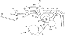
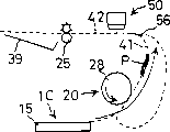
Fig. 1 is the synoptic diagram of digital copier (copier) structure according to the embodiment of the invention;
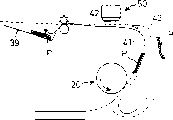
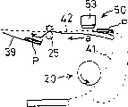
Fig. 2 is the view that the second imaging area peripheral structure in the print unit that is arranged on digital copier is shown;
Fig. 3 is the view that the structure of the control module that comprises in the digital copier is shown;
Fig. 4 is the process flow diagram that is illustrated in the order of the processing procedure of carrying out in the control module of digital copier;
Fig. 5 is the view how the aid illustration Flame Image Process carries out in the Flame Image Process district that constitutes a control module part;
Fig. 6 is the process flow diagram that is illustrated in the order of the processing procedure of carrying out in the Flame Image Process district, is used to judge that the data that provided are monochromatic image data or color image data;
Fig. 7 is the process flow diagram that is illustrated in the order that embodies the processing procedure of carrying out in the digital copier of the present invention, is used to carry out forming monochrome image;
The view in recording paper transportation path footpath under Fig. 8 A to 8C situation that to be aid illustration carry out in digital copier for the forming monochrome image in the single face imaging pattern;
The view in recording paper transportation path footpath under Fig. 9 A to 9C situation that to be aid illustration carry out in digital copier for the forming monochrome image in the double-face imaging pattern;
Figure 10 is the process flow diagram that is illustrated in the order of the processing procedure of carrying out in the digital copier, is used to carry out colour imaging;
The view in recording paper transportation path footpath under Figure 11 A to 11C situation that to be aid illustration carry out in digital copier for the colour imaging in the single face imaging pattern;
The view in recording paper transportation path footpath under Figure 12 A to 12E situation that to be aid illustration carry out in digital copier shown in Figure 10 for the colour imaging in the double-face imaging pattern;
Figure 13 is the process flow diagram that is illustrated in another example of the processing procedure of carrying out in the digital copier, is used to carry out the colour imaging operation;
The view in recording paper transportation path footpath under Figure 14 A to 14F situation that to be aid illustration carry out in digital copier shown in Figure 13 for the colour imaging in the double-face imaging pattern;
Figure 15 is the process flow diagram that is illustrated in the order of the processing procedure of carrying out in the digital copier, is used for carrying out the picture that is mixed into of single face imaging pattern;
Figure 16 is the process flow diagram that is illustrated in the order of the processing procedure of carrying out in the digital copier, is used for carrying out the picture that is mixed into of double-face imaging pattern;
Figure 17 A to 17E is the recording paper transportation path footpath under the situation of carrying out in the digital copier shown in Figure 15 of view aid illustration is imaged on to(for) the mixing in the single face imaging pattern;
Figure 18 A to 18F is the recording paper transportation path footpath under the situation of carrying out in the digital copier shown in Figure 16 of view aid illustration is imaged on to(for) the mixing in the double-face imaging pattern;
Figure 19 is the process flow diagram that is illustrated in another example of the processing procedure of carrying out in the digital copier, is used for carrying out the mixing imaging operation at the single face imaging pattern;
Figure 20 is the process flow diagram that is illustrated in another example of the processing procedure of carrying out in the digital copier, is used for carrying out the mixing imaging operation in the double-face imaging pattern;
Figure 21 A to 21F is the recording paper transportation path footpath under the situation of carrying out in the digital copier shown in Figure 19 of view aid illustration is imaged on to(for) the mixing in the single face imaging pattern;
Figure 22 A to 22G explains the auxiliary view that is imaged on recording paper transportation path footpath under the situation of carrying out in the digital copier shown in Figure 19 for the mixing in the single face imaging pattern;
Figure 23 illustrates the table that concerns between recording paper deflection, recording chart size and the fixation unit number of pass times.
Embodiment
Referring now to accompanying drawing, the preferred embodiment of the present invention is described hereinafter.
Below, will make explanation according to the imaging device of the embodiment of the invention.Regard digital copier as an example at this.Fig. 1 is the synoptic diagram that illustrates according to embodiment of the invention digital copier structure.Fig. 2 is the view that the second imaging area peripheral structure in the print unit that is arranged on digital copier is shown.Digital copier 1 is designed to have scanning element 1A at an upper portion thereof, has print unit 1B in the middle, has paper supply unit 1C in its underpart, thereby presents the configuration of U-shaped basically.
Scanning element 1A is provided with original paper platform of being made by transparent hard glass 15 and the scanning optics 10 that is positioned at original paper platform 15 belows.Original paper platform 15 is arranged to be exposed on the end face of digital copier 1.Scanning optics 10 comprises illuminator 11; Catoptron 12a to 12c; Lens 13; And ccd image sensor (hereinafter referred is made " CCD ") 14.Exposure lamp (the exposure lamp) 11 and catoptron 12a reciprocally move on the direction that is parallel to original paper platform 15 lower surfaces together, thereby the image load-bearing surface that is placed on the original paper on original paper platform 15 upper surfaces is exposed in the light.Catoptron 12b and 12c move back and forth with 1/2nd speed of illuminator 11 and catoptron 12a on the direction that is parallel to original paper platform 15 lower surfaces, thereby send then distribution of light from the reflection of original paper image load-bearing surface to lens 13 from illuminator 11, it is constant that its optical path length keeps.Lens 13 act as the light that the image load-bearing surface from original paper is reflected and focus on the optical receiving surface of CCD14.CCD14 exports light receiving signal according to the light quantity that incides on the optical receiving surface.The imaging area of describing hereinafter from the light receiving signal of CCD14 output converts digital signal to.Digital signal offers print unit 1B as view data after being subjected to predetermined imaging operation.
In this example, although having adopted fixedly for employing, the situation of the scanning element of original paper read method is illustrated, promptly, the scanning element that is placed on the view data of the original paper of fixed position on the original paper platform reads by the scanning optics that is parallel to the original paper platform and moves, but adopt the scanning element of mobile original paper read method or adopt mobile original paper read method and fixedly the original paper read method combination can for use.
First imaging area 20 is made of following basically: photoelectric conducting drum 28; Charger 29; Laser scan unit (hereinafter referred is made " LSU ") 30; Developing cell 31; Transfer printing unit 32; And fixation unit 23.Charhing unit 29, LSU30, developing cell 23, transfer printing unit 32 etc. are provided with around photoelectric conducting drum 28 with the sense of rotation of this order along photoelectric conducting drum 28.Fixation unit 23 is arranged on the downstream of the relative position and the transfer printing unit 32 of photoelectric conducting drum 28 along main transfer path 41.In first imaging area 20, imaging is following to be carried out.At first, charhing unit 29 is applied to predetermined electric charge on the surface of photoelectric conducting drum 28 equably, and this photoelectric conducting drum 28 rotates with predetermined process speed in direction shown in the arrow A.Then, the LSU30 radiation is according to the laser of view data modulation.At this moment, electrostatic latent image is formed on the surface of photoelectric conducting drum 28.Developing cell 31 is provided to developer on the surface of photoelectric conducting drum 28, form electrostatic latent image by developer roll 31a on this surface, thereby electrostatic latent image as the developer image as seen.Transfer printing unit 32 will be carried on the surface of photoelectric conducting drum 28 lip-deep developer image to recording chart P.Attention: the surface that has experienced the photoelectric conducting drum 28 of transport process is removed by unshowned cleaner and electric charge remover and remains in lip-deep residue developer and electric charge, thereby photoelectric conducting drum 28 can be used for imaging process once more.The function of fixation unit 23 is as follows.As shown in Figure 2, warm-up mill 23a and backer roll 23b under predetermined pressure each other pressure contact so that the recording chart P in zone applies heat and pressure between by two rollers.Be transferred on the recording chart P toner image at high temperature with pressure under pressurized, heat fixation is to recording chart P thus.
At print unit 1B, second imaging area 50 is arranged in the transfer path, and this path design is used to discharge paper (hereinafter being called " row's paper transfer path ") 42, and the downstream of this path and main transfer path 41 is continuous on paper conveyance direction.In second imaging area 50, as shown in Figure 2, the carriage 53 that combines ink gun 53a and print cartridge 53b is supported, to such an extent as to can move back and forth via axle 54 at main scanning direction, and platen 55 is arranged in above whole row's paper transfer path 42 carriage 53.In addition, among row's paper transfer path 42, act as the transfer roller 51a of transmission parts and the dead ahead that 52a is arranged on the present invention's second imaging area.Being placed on transfer roller 51a on the opposite flank of carriage 53 and platen 55 relative positions is supported at vertical and horizontal direction with 52a and all rotates freely.In addition, star roller 51b and 52b are supported on the top of transfer roller 51a and 52a respectively at their axis place.Recording chart P is transmitted when being clipped between transfer roller 51a, 52a and star roller 51b, the 52b.By in second imaging area 50, utilizing star roller 51b and 52b and star roller 25b described below, each roller and be formed with on it that surface in contact between the image load-bearing surface of recording chart p of ink image is long-pending to be reduced to some extent prevents to have in the image that is obtained stain to produce thus.
Note, except main transfer path 41 and row's paper transfer path 42, in print unit 1B, also be formed with auxiliary transfer path 43.Between main transfer path 41 and row's paper transfer path 42 is the baffle plate 56 that can swing setting, is used to close auxiliary transfer path 43.
In the print unit 1B, except the warm-up mill 23a and backer roll 23b that constitute fixation unit 23, be provided with along main transfer path 41 and stop roller (a resist roller) 22, it is arranged on the transmission parts in the present invention first imaging area dead ahead.Before photoelectric conducting drum 28 rotation, stop that roller 22 will stop once from the recording chart P that paper supply unit 1C enters, then and the synchronous leader record paper of the rotation of photoelectric conducting drum 28 to the zone between photoelectric conducting drum 28 and the transfer printing unit 32.In other words, stop that roller 22 keeps not rotation at recording chart P when paper supply unit 1C infeeds, yet, begin rotation when the leading section of the toner image of carrying overlaps on the fore-end of recording chart P and the photoelectric conducting drum 28 at the relative position place of photoelectric conducting drum 28 and transfer printing unit 32.
In digital copier 1, discharge tray 39 is connected on the side of print unit 1B, thereby is positioned in the gap between scanning element 1A and the paper supply unit 1C.Being formed on row's paper transfer path 42 in the print unit 1B act as downstream side with main transfer path 41 and forms with discharge tray 39 on paper conveyance direction and be communicated with.Row's paper transfer path 42 has the exit roller 25a that cooperates in pairs with star roller 25b at its discharge tray 39 sides.Exit roller 25a is designed at both forward and reverse directions all rotatable as transfer roller 51a and 52a.Exit roller 25a and transfer roller 51a and 52a are used to be implemented in the double-face imaging function in first imaging area 20.
In other words, be used on surface of first imaging area, 20 recording chart P, forming in the single face imaging pattern situation of image, baffle plate 56 is set in the position by solid line indication among Fig. 2, transfer roller 51a, 52a and the vertical in the clockwise direction rotation of exit roller 25a, as shown in Figure 2.Under this state, the recording chart P by fixation unit 23 passes through row's paper transfer path 42, is expelled to thus on the discharge tray 39.In contrast, in the situation that is used on recording chart P is two-sided, forming the double-face imaging pattern of image, on the recording chart first surface, form in the image process (first surface imaging), when the rear end part of recording chart P passes through transfer roller 52a, baffle plate 56 is transferred to the position by dotted line indication among Fig. 2, and transfer roller 51a, 52a and exit roller 25a are in the counter-clockwise direction reverse rotation, as shown in Figure 2.Under this state, recording chart P is directed to auxiliary transfer path 43, all shifts when advancing to assist in the transfer path 43 on the whole surface of recording chart P then, and baffle plate 56 is transferred to the position by solid line indication among Fig. 2.Be conducted through upstream side to the first imaging area 20 of main transfer path 41 by the recording chart P of main transfer path 43 upstream sides, its surface turns.Then, experience is after the second surface epigraph of recording chart forms (second surface imaging), and recording chart P is discharged on the discharge tray 39, as shown in Figure 2 by transfer roller 51a, 52a and the exit roller 25a of vertical rotation in the clockwise direction.
Notice that in the following description, transfer roller 51a and star roller 51b are defined as transfer roller 51; The combination of transfer roller 52a and star roller 52b is defined as transfer roller 52; The combination of exit roller 25a and star roller 25b is defined as exit roller 25.
Fig. 3 is the view that the control module structure that is combined in the digital copier is shown.The control module 100 of digital copier constitutes by top plane view is connected to the CPU101 that comprises ROM102 and RAM103 as memory block 104, back side image memory block 105 and Flame Image Process district 106.Top plane view is stored end face view data and back side image data respectively as memory block 104 and back side image memory block 105, and these data are to read from the end face and the back side of individual original paper respectively by scanning element 1A.
Flame Image Process district 106 carries out predetermined picture processing operation for being stored in top plane view as the view data in memory block 104 and the back side image memory block 105.Be connected to the controller 107 that is arranged on the LSU30 in first imaging area 20 in the Flame Image Process district 106, and the driver 108 that is arranged on the ink gun 53a in second imaging area 50.Flame Image Process district 106 will experience the monochromatic image data that predetermined picture handles at predetermined instant and offer controller 107, also will experience the color image data that predetermined picture handles at predetermined instant and offer driver 108.
Fig. 4 is the process flow diagram that is illustrated in the order of the processing procedure of carrying out in the control module of digital copier.When energized, in step s1, the CPU101 of control module 100 sets the input that becomes the imaging request and prepares after starting.After having imported the imaging request, in step s2, CPU101 judges whether the original paper that is used for image information is the single face original paper, if not, in step s3, judge whether this original paper is two-sided original paper.Make the single face original paper if this original paper is judged, then in step s4, CPU101 reads the image of original paper by scanning element 1A.Then, in step s5, the image data storage that reads top plane view as memory block 104 in the time, in step s6, in Flame Image Process district 106, predetermined picture is handled to operate in and is stored in top plane view as carrying out on the view data in the memory block 104.On the other hand, if being used for the original paper of imaging is judged and makes two-sided original paper, then in step s7, CPU101 is by the end face reads image data of scanning element 1A from original paper, then, in step s8, with image data storage top plane view as memory block 104 in, also the image data storage that will read from the original paper back side is overleaf the image memory block 105.Then, in step s9, in Flame Image Process district 106, carry out predetermined picture processing operation for the view data that is stored in end face and back side image memory block 104 and 105.
Then, in step s10 to s12, CPU101 judges that whether be stored in top plane view includes only monochromatic image data, includes only color image data as the view data in memory block 104 and the back side image memory block 105, perhaps comprises the blended image data that is constituted by monochromatic and color image data.Only store monochromatic image data if judge, then in step s13, CPU101 carries out the imaging based on the electrostatic printing system in first imaging area 20.Only store color image data if judge, then in step s14, CPU101 carries out the colour imaging based on ink-jet system in second imaging area 50.Store blended image data if judge, then in step s15, CPU101 is mixed into picture in first and second imaging areas 20 and 50.In step 16, have next original paper if judge, then process is back to step s2.Under the imaging request, CPU101 repeatedly carries out treatment step s2 to step s15 on each original paper.
Note, in Flame Image Process district 106, be stored in image memory block 104 and 105 from carrying, and offer controller 107 and driver 108 to be different from the mode that adopts in the tradition by the blended image data that reads monochromatic and the original paper of coloured image in conjunction with the image that obtains.That is, in traditional imaging device, two discrete Flame Image Process districts are monochromatic image data and color image data and be provided with separately.In addition, in the situation of handling blended image data, for each of the original paper end face and the back side, corresponding view data is divided into monochromatic image data and color image data, and institute's divided image data is stored in end face and the back side image memory block after the experience predetermined picture is handled.
Under the contrast, embody Flame Image Process of the present invention district 106 and have following distinguished feature.As shown in Figure 5, the blended image data that reads from original paper end face and the back side experiences single imaging area 106 after predetermined picture handles, be stored in top plane view as memory block 104 and back side image memory block 105, and be not divided into monochromatic image data and color image data.Then, in first and second imaging areas 20 and 50, during the imaging, make whether the view data that reads is the decision of monochromatic image data or color image data from end face and back side image memory block 104 and 105.After this, monochromatic image data offers the controller 107 of LSU30, and color image data offers the driver 108 of ink gun 53a.
Yet, it should be noted that the color image information in the monochrome image information in first imaging area 20 and second imaging area 50 is not to carry out simultaneously.Therefore, in Flame Image Process district 106, when electrostatic printing system forming monochrome image is carried out in first imaging area 20, have only and judge that the data of making monochromatic image data just can offer first imaging area 20; And, when colour imaging when second imaging area 50 carries out, have only and judge that the data make color image data just can offer second imaging area 50.
In this way, Flame Image Process district 106 can store blended image data, and will data not be divided into monochromatic image data and color image data.This helps to reduce the memory capacity of end face and back side image memory block 104 and 105.Another advantage is that monochromatic image data and color image data can handle in same processing path.This helps the structure of simplified image treatment region 106.
In this case, whether be that the monochromatic image data or the judgement of color image data should be easy to make exactly ideally for the data that offer controller 107 and driver 108 from Flame Image Process district 106.Given this, for example, according to the process shown in Fig. 6 process flow diagram, Flame Image Process district 106 is designed to: on the basis of each tone value of the primary colors R (redness) that is used to add, G (green) and B (blueness), be that monochromatic image data or color image data judge to the data that provide.
Among Fig. 6, at step s21 to s23, Flame Image Process district 106 judges whether the difference of the tone value between color R, G and the B remains in the preset range.If the difference of the tone value between color R, G and the B remains in the preset range, then in step s30, Flame Image Process district 106 judgment data are monochromatic image datas.This judgement is that the tone value at color R, G and B is equal to each other basically in gray level image on the basis of this fact and makes.
If the difference of the tone value of any two kinds of colors exceeds preset range among R, G and the B, then in Flame Image Process district 106, in step s24 to s26, the tone value of color compares with predetermined threshold separately.If all tone values are all greater than predetermined threshold, then in step s30, Flame Image Process district 106 judgment data are monochromatic image datas.This judgement is to make color R, G and B show the basis of high this fact of tone value in gray level image on.
If the difference of the tone value of any two kinds of colors all remains in the preset range among R, G and the B, then in Flame Image Process district 106, in step s27 to s29, the tone value of color compares with predetermined threshold separately.If all tone values all are equal to or less than predetermined threshold, then in step s30, Flame Image Process district 106 judgment data are monochromatic image datas.This judgement is to make color R, G and B show the basis of this fact of low key tone value in gray level image on.In the process of step s21 to s29, judge that those view data make monochromatic image data are judged to make color image data in step s31.
According to aforementioned process, be that the monochromatic image data or the judgement of color image data can be easy to make accurately about the data that provide.
Then, hereinafter will be respectively at the situation of the situation that forms monochrome image, formation coloured image and the situation that forms vision-mix, to being described of observed recording chart delivery status and view data treatment state during the imaging of in digital copier 1, carrying out.In the explanation, " front end of recording chart P " refers to the end of recording chart P in the side of the main transfer path 41 of recording chart P hereinafter, as being placed at recording chart P under the state on the paper feed pallet 16 or it is placed under the state in the input tray 17 observed.On the other hand, " rear end of recording chart P " refers to that end relative with recording chart P front end.
(1) forming monochrome image
The forming monochrome image in first imaging area 20 based on the electrostatic printing system carries out following.As from shown in Fig. 7 process flow diagram, at first, in step s101 and s102, CPU101 judges what whether imaging was carried out based on the single face imaging pattern that forms image on recording chart P one side, is based on also that the double-face imaging pattern that forms image on recording chart P is two-sided carries out.In the single face imaging pattern, in step s103, CPU101 is in order from corresponding to reading the monochromatic image data that is used for end face the part that will be formed on the image section on the recording chart P leading section, this data storage top plane view as memory block 104 in.Thus obtained monochromatic image data can synchronously offer controller 107 by Flame Image Process district 106 when then stopping the driving of roller 22 with setting.In other words, Flame Image Process district 106 exports monochromatic image data as follows to controller 107, that is, image is formed on the recording chart P gradually by the order from the fore-end of recording chart to its rear end part.Thus, in first imaging area 20, electrostatic latent image is formed on the surface of photoelectric conducting drum 28 by LSU30.Then, in step s104, under the control of CPU101, utilize the developer that provides from developing cell 31, formed electrostatic latent image is as developed image and visual.Then, in step s105, in the time interval by the zone between photoelectric conducting drum 28 and the transfer printing unit 32, shown in Fig. 8 A, the developer image is transferred on the recording chart P by transfer printing unit 32 at the record paper P that infeeds from paper supply unit 1C.
Then, at step s106, under CPU101 control, fixation unit 23 applies heat and pressure to recording chart P, so the developer image is bonded on the recording chart P.Then, in step s107, baffle plate 56 is set in the position of solid line indication among Fig. 2, so that be communicated with between main transfer path 41 and the row's paper transfer path 42, allows recording chart P by second imaging area 50, shown in Fig. 8 B.At last, in step s108, shown in Fig. 8 C, recording chart P carries ventricumbent mode with its monochrome image and is discharged on the discharge tray 39, that is, and and in ventricumbent mode.
In the situation of double-face imaging pattern, in step s109, CPU101 reads the monochromatic image data that is used for the back side in the part corresponding to the data that will be formed on the parts of images on the recording chart P leading section from be stored in back side image memory block 105 in order.Thus obtained monochromatic image data stops that with setting the driving of roller 22 constantly synchronously offers first imaging area 20 by Flame Image Process district 106.That is, to such an extent as to Flame Image Process district 106 exports back side monochromatic image data to controller 107 images in mode so is formed on gradually on the recording chart P by the order from the fore-end of recording chart to its rear end part.Then, in step s110 to s113, under the control of CPU101, according to the treatment step identical with step s104 to s107, shown in Fig. 9 A, on its first surface, carry developer record images paper P this moment owing to the result who operates by first imaging area 20 and be directed to row's paper transfer path 42.Subsequently, in step s114, after exit roller 25 stops, rearward end by second imaging area 50 is by exit roller 25 clampings, in step s115, baffle plate 56 is set in the position of dotted line indication among Fig. 2, so that be communicated with between row's paper transfer path 42 and the auxiliary transfer path 43, thereby transfer roller 51,52 and exit roller 25 reverse rotations are shown in Fig. 9 B.Thus, recording chart P is directed passing through once more auxiliary transfer path 43 to main transfer path, and the upset of the surface of recording chart down.
After this, in step s116, CPU101 in order from be stored in top plane view as the memory block 104 corresponding to reading the monochromatic image data that is used for end face in the partial data that will be formed on the parts of images on the recording chart P rearward end.Thus obtained monochromatic image data stops that with setting the driving of roller 22 constantly synchronously offers first imaging area 20 via Flame Image Process district 106.That is, to such an extent as to Flame Image Process district 106 exports back side monochromatic image data to controller 107 images in mode so is formed on gradually on the recording chart P by the order from the rear end part of recording chart to its fore-end.Then, in step s117 to s121, under the control of CPU101, according to the treatment step identical with step s104 to s108, shown in Fig. 9 C, at this moment, on its first surface, carry developer record images paper P as the result who operates by first imaging area 20 by row's paper transfer path 42, thereby be expelled on the discharge tray 39 in ventricumbent mode.
As mentioned above, forming with the double-face imaging pattern in the situation of monochrome image, the experience imaging of the back side of recording chart P is early than its end face, and reason is as follows.Even be formed under the situation of many recording chart P on two-sided the number of pages (sorting operation) that also not needing sorts is discharged to the recording chart on the discharge tray 39 at the image that strides across page boundary.In addition, back side monochromatic image data is in order from corresponding to reading the partial data that will be formed on the parts of images on the recording chart P leading section, and the end face monochromatic image data is in order from corresponding to reading the partial data that will be formed on the parts of images on the recording chart P rearward end, this be because, for recording chart P is being spun upside down in twice by main transfer path 41, after finishing back side imaging, recording chart P is gone back in transport process.As a result, be used for back side imaging recording chart P direct of travel be used for the opposite of end face imaging.
(2) color image information
The colour imaging in second imaging area 50 based on ink-jet system carries out following.As from shown in Figure 10 process flow diagram, at first, in step s201 and s202, CPU101 judges what whether imaging was carried out based on the single face imaging pattern that forms image on recording chart P one side, is based on also that the double-face imaging pattern that forms image on recording chart P is two-sided carries out.In the single face imaging pattern, in step s203, under the control of CPU101, in order from being stored in top plane view as the end face color image data in the memory block 104 corresponding to reading the partial data that will be formed on the parts of images on the recording chart P rearward end.Simultaneously, in step s204, under the control of CPU101, the record paper P that enters from paper supply unit 1C transmits by main transfer path 41, and in step s205, baffle plate 56 is arranged on the position of solid line indication among Fig. 2, arrives row's paper transfer path 42 with leader record paper P.Then, in step s206, shown in Figure 11 A, exit roller 25 stops, and the rearward end of recording chart P is by exit roller 25 clampings.
Then, in step s207, under the control of CPU101, baffle plate 56 is set in the position of dotted line indication among Fig. 2, so that be communicated with between row's paper transfer path 42 and the auxiliary transfer path 43.Under this state, shown in Figure 11 B, exit roller 25 reverse rotations are till transmit on the direction shown in the arrow b in Figure 11 the rear end of recording chart P.Then, in step s208, with the moment constantly synchronous with the driving of set giving transfer roller 52 (moment that overlaps with color image data corresponding to the image rearward end in the rear end of recording chart P), the end face color image data offers the driver 108 of ink gun 53a via Flame Image Process district 106.After recording chart P is regulated in the transmission of arrow b direction and to the operation of input tray 53 in second imaging area 50 and ink gun 53a, on recording chart P, carry out colour imaging.In other words, Flame Image Process district 106 exports the end face color image data to driver 108 in mode so, to such an extent as to image is to be formed on gradually on the recording chart P from the order of recording chart P rearward end to its leading section.
At this moment, at second imaging area 50, wherein imaging is carried out as follows: at the input tray 53 that includes ink gun 53a in the time interval that the main scanning direction perpendicular to recording chart P direction of transfer moves back and forth, printing ink is from the nozzle ejection of ink gun 53a, and recording chart P is transmitted off and on equals nozzle in the distance that is parallel to arrangement interval on the auxiliary scanning direction of direction of transfer.Thus, in step s209, the single line of each input tray 53 moves when finishing, and CPU101 judges whether to finish the imaging operation based on whole color image datas.
In addition, because baffle plate 56 provides the connection between row's paper transfer path 42 and the auxiliary transfer path 43, so recording chart P is directed experiencing the ink-jet system colour imagings at second imaging area 50 simultaneously in the into auxiliary transfer path 43 in its back-end.Thus, occurrence record paper P oneself enters in the fixation unit 23 that is arranged in the main transfer path 41 never.
After finishing colour imaging based on whole color image datas, in step s210, under the control of CPU101, shown in Figure 11 C, exit roller 25 and transfer roller 51,52 normally rotate, thereby transmit on the arrow a indicated direction of recording chart P in row's paper transfer path 42.At last, recording chart P is disposed on the discharge tray 39 in mode so, to such an extent as to its image loading end up, that is, and supine mode.
Notice that in this example, recording chart P is discharged on the discharge tray 39 in supine mode, so that shorten the required time of imaging.Perhaps, for recording chart P is discharged on the discharge tray 39 in the mode of facing down, to eliminate the needs that on plurality of sheets of paper, form the required sorting operation of consecutive image, the recording chart P that has experienced the colour imaging of being carried out by second imaging area 50 is directly guided to auxiliary transfer path 43, by main transfer path 41 and row's paper transfer path 42, be discharged from then with this order.
In addition, in this example, in order to promote to deposit to the drying of the printing ink on the recording chart P, at recording chart P in the time interval that arrow b direction transmits, be imaged on second imaging area 50 and carry out, close by the recording chart P of second imaging area 50 with the fixation unit 23 that remains under the condition of high temperature.At this, in order further to shorten the required time of imaging, during transmitting on the arrow a direction shown in Figure 11 A, carry out colour imaging at second imaging area at paper, paper directly is expelled to discharge tray 39.
In the situation of double-face imaging pattern, in step s211 to s218, under the control of CPU101, according to the process identical with step s203 to s209, shown in Figure 12 A and 12B, at recording chart P in arrow b direction along in the time interval that row's paper transfer path 42 transmits, in second imaging area 50, on the first surface of recording chart P, carry out the end face colour imaging.In other words, Flame Image Process district 106 exports the end face color image data to driver 108 in mode so, to such an extent as to image is to be formed on gradually on the recording chart P from the order of recording chart P rearward end to its leading section.At this moment, under the control of CPU101, baffle plate 56 is arranged on the position of dotted line indication among Fig. 2, so that be communicated with between row's paper transfer path 42 and the auxiliary transfer path 43.Then, under the control of CPU101, transfer roller 51,52 and exit roller 25 reverse rotations, thus recording chart P is directed to auxiliary transfer path 43.
Then, in step s219, CPU101 is in order from corresponding to reading the back side color image data that is stored in the back side image memory block 105 partial data that is formed on the parts of images on the recording chart P rearward end.Then, in step s220, shown in Figure 12 C, recording chart P is conducted through auxiliary transfer path 43 to main transfer path 41, in step s221, baffle plate 56 is arranged on the position of solid line indication among Fig. 2, so that be communicated with between row's paper transfer path 42 and the main transfer path 41, shown in Figure 12 D, leader record paper P is to arranging paper transfer path 42.
In this way, in step s222, under the control of CPU101, for second of the recording chart P that advances in arrow a direction along row's paper transfer path 42, with the moment constantly synchronous with the driving of set giving transfer roller 51 (moment that overlaps with color image data corresponding to the image rearward end in the rear end of recording chart P), back side color image data offers the driver 108 of ink gun 53a via Flame Image Process district 106.So, carry out back side colour imaging by second imaging area 50.In other words, Flame Image Process district 106 exports back side color image data to driver 108 in mode so, to such an extent as to image is to be formed on gradually on the recording chart P from the order of recording chart P rearward end to its leading section.Then, in step s223, under the control of CPU101, when finishing the imaging based on whole back sides color image data, shown in Figure 12 E, in step s210, recording chart P is disposed on the discharge tray 39 in mode so, to such an extent as to its end face that carries coloured image down, that is, and ventricumbent mode.
In this embodiment, back side colour imaging is by carrying out at arrow a direction moving recording paper P along row's paper transfer path 42.In addition, as the end face colour imaging, it also can be by carrying out at arrow b direction moving recording paper P along row's paper transfer path 42.Figure 13 shows the process flow diagram that is used to explain this operation.
In the situation of double-face imaging pattern, shown in the process flow diagram and Figure 14 A and 14B of Figure 13, the step s211 to s218 according to shown in Figure 10 process flow diagram carries out the end face colour imaging.After this, in step s230, CPU101 is in order from corresponding to reading the back side color image data that is stored in the back side image memory block 105 partial data that is formed on the parts of images on the recording chart P rearward end.Then, in step s231, shown in Figure 14 C, recording chart P is conducted through auxiliary transfer path 43 and arrives main transfer path 41, in step s232, baffle plate 56 is arranged on the position of solid line indication among Fig. 2, so that be communicated with between row's paper transfer path 42 and the main transfer path 41, recording chart P is guided to row's paper transfer path 42.
In step s233, under the control of CPU101, shown in Figure 14 D, be allowed to after arrow a direction is passed through second imaging area 50 at recording chart P, exit roller 25 stops, and the front end of recording chart P is by exit roller 25 clampings.Thereby in step s234, under the control of CPU101, baffle plate 56 is arranged on the position of dotted line indication among Fig. 2, so that be communicated with between row's paper transfer path 42 and the auxiliary transfer path 43.Under this state, shown in Figure 14 E, exit roller 25 reverse rotations, till the front end of recording chart P arrives transfer roller 52, thereby recording chart P transmits on arrow b direction.Then, in step s235, under the control of CPU101, with the moment constantly synchronous with the driving of set giving transfer roller 52 (moment that overlaps with color image data corresponding to the image rearward end in the rear end of recording chart P), back side color image data offers the driver 108 of ink gun 53a via Flame Image Process district 106.After recording chart P is regulated in the transmission of arrow b direction and to the operation of input tray 53 in second imaging area 50 and ink gun 53a, on recording chart P, carry out colour imaging.In other words, Flame Image Process district 106 exports the end face color image data to driver 108 in mode so, to such an extent as to image is to be formed on gradually on the recording chart P to the order of end thereafter from recording chart P leading section.
When the imaging based on whole back sides color image data in step s236 is finished, shown in Figure 14 F, in step s210, under the control of CPU101, exit roller 25 and transfer roller 51,52 normally rotate, thereby transmit on the arrow a direction of recording chart P in row's paper transfer path 42.At last, recording chart P is disposed on the discharge tray 39 in mode so, so that its end face that carries coloured image down, that is, and ventricumbent mode.
It should be noted in the colour imaging process in the double-face imaging pattern, recording chart P is at primary importance experience end face colour imaging, reason is as follows: even under consecutive image is formed on situation on the plurality of sheets of paper, also do not need the recording chart P that carries out with respect to being expelled on the discharge tray 39 to carry out sorting operation.In addition, in the said process, although the black image data that is included in the color image data also experiences the ink-jet system imaging of carrying out in second imaging area 50, by adopting and the identical process of picture that is mixed into described below, the black image data that is included in the color image data can experience the electrostatic printing system imaging that carries out in first imaging area 20.This makes can no longer need provide the black print cartridge in second imaging area 50, the advantage that causes is: the weight of the designs simplification of second imaging area 50 and input tray 53 is lighter.
(3) be mixed into picture
The picture of realizing by electrostatic printing system forming monochrome image that will carry out in first imaging area 20 and the ink-jet system colour imaging that carries out in second imaging area 50 combination that is mixed into will be described below.Shown in the process flow diagram shown in Figure 15 and 16, at first, in step s301 and s302, CPU101 judges that imaging is based on recording chart P and goes up simultaneously that the single face imaging pattern that forms image carries out, and is based on also that the double-face imaging pattern that forms image on recording chart P is two-sided carries out.
In the single face imaging pattern, the electrostatic printing system forming monochrome image that carries out in first imaging area 20 that is arranged on recording chart P transfer path upstream side is early than the ink-jet system colour imaging that carries out in second imaging area 50.Imaging in first imaging area 20 is following to be carried out.At first, in step s303, under the control of CPU101, be stored in top plane view as the end face monochromatic image data in the memory block 104 in order from reading corresponding to the partial data that is formed on the parts of images on the recording chart P leading section.As above the view data of Huo Deing synchronously offers controller 107 via Flame Image Process district 106 with the driving moment of setting to stopping roller 22.In other words, Flame Image Process district 106 exports the end face monochromatic image data to controller 107 in mode so, so that image is to be formed on gradually on the recording chart P from the order of recording chart P rearward end to its leading section.Thus, in first imaging area 20, electrostatic latent image is formed on the surface of photoelectric conducting drum 28 by LSU30.Then, in step s304, under the control of CPU101, utilize the developer that provides from developing cell 31, formed electrostatic latent image is as developed image and visual.Then, in step s105, in the time interval by the zone between photoelectric conducting drum 28 and the transfer printing unit 32, shown in Figure 17 A, the developer image is transferred on the recording chart P by transfer printing unit 32 at the record paper P that infeeds from paper supply unit 1C.
Then, at step s306, under CPU101 control, fixation unit 23 applies heat and pressure to recording chart P, so the developer image is bonded on the recording chart P.Then, in step s307, baffle plate 56 is set in the position of solid line indication among Fig. 2, so that be communicated with between main transfer path 41 and the row's paper transfer path 42, thereby permission recording chart P in step s308 advances by second imaging area 50, shown in Figure 17 B with arrow a direction.Then, drive exit roller 25 and stop the rotation making it, recording chart P is by exit roller 25 clampings.Under this state, in step s309, under the control of CPU101, be stored in top plane view as the end face color image data in the memory block 104 in order from corresponding to reading the partial data that is formed on the parts of images on the recording chart P rearward end, in step s310, baffle plate 56 is arranged on the position of dotted line indication among Fig. 2, so that be communicated with between row's paper transfer path 42 and the auxiliary transfer path 43.Then, transfer roller 51,52 and exit roller 25 reverse rotations make recording chart P transmit in arrow b direction, and recording chart P is conducted through auxiliary transfer path 43 to main transfer path 41, shown in Figure 17 C then.
After this, in step s310, under the control of CPU101, baffle plate 56 is arranged on the position of solid line indication among Fig. 2, so that be communicated with between row's paper transfer path 42 and the main transfer path 43, shown in Figure 17 D, makes recording chart P be directed to row's paper transfer path 42.Then, in step s312, with the moment constantly synchronous with the driving of set giving transfer roller 52 (moment that overlaps with color image data corresponding to the image rearward end in the rear end of recording chart P), the end face color image data offers the driver 108 of ink gun 53a via Flame Image Process district 106.So the first surface for the recording chart P that advances along row's paper transfer path 42 in arrow a direction carries out the end face colour imaging by second imaging area 50.In other words, Flame Image Process district 106 exports the end face color image data to driver 108 in mode so, so that image is formed on the recording chart P gradually by the order from the rear end part of recording chart to its fore-end.When in step s313, finishing the colour imaging based on whole end face color image datas, shown in Figure 17 E, in step s314, under the control of CPU101, recording chart P is disposed on the discharge tray 39 in mode so, so that it carries facing up of end face monochrome and coloured image, that is, and in supine mode.
In this way, in the single face imaging pattern, except main transfer path 41 and row's paper transfer path 42, recording chart P also transmits along auxiliary transfer path 43 equally.Because this structure, even first and second imaging areas 20 and 50 are arranged to form image on via the surface that differs from one another of main transfer path 41 by the recording chart P of row's paper transfer path 42, also can on the same surface of recording chart P, carry out by the forming monochrome image of first imaging area, 20 execution and the colour imaging of carrying out by second imaging area 50.
Notice that in above-mentioned example, recording chart P is disposed on the discharge tray 39 to shorten the imaging required time in supine mode.In addition, for recording chart P is discharged on the discharge tray 39 in the mode of facing down, no longer need on many recording chart P, form the desired sorting operation of consecutive image, experience recording chart P monochromatic and colour imaging and guided to auxiliary transfer path 43 once more, pass through main transfer path 41 and row's paper transfer path 42 then, and be discharged from.
Shown in Figure 16 process flow diagram, in the double-face imaging pattern, in step s315, CPU101 is in order from corresponding to reading the back side monochromatic image data that is stored in the back side image memory block 105 partial data that is formed on the parts of images on the recording chart P leading section.Thus obtained view data offers first imaging area 20 via Flame Image Process district 106.Then, in step s316 to s319, according to the process identical with step s304 to s307, on the first surface of recording chart P, carry out back side forming monochrome image, then, shown in Figure 18 A, on its first surface, carrying developer record images paper P as the result who operates by first imaging area 20 and be directed to row's paper transfer path 42.In other words, Flame Image Process district 106 exports back side monochromatic image data to controller 107 in mode so, so that image forms gradually from rear end part to its fore-end of recording chart P.Then, in step s320, under CPU101 control, shown in Figure 17 B, drive exit roller 25 and stop the rotation making it, the recording chart P by second imaging area 50 is by exit roller 25 clampings.Then, among the step s321, in order from being stored in top plane view as the end face color image data in the memory block 104 corresponding to reading the partial data that is formed on the parts of images on the recording chart P rearward end.
Then, at step s322, under CPU101 control, baffle plate 56 is set in the position of dotted line indication among Fig. 2, so that be communicated with between main transfer path 41 and the auxiliary transfer path 43.Under this state, shown in Figure 18 C, exit roller 25 reverse rotations, till the rear end of recording chart P arrives transfer roller 52, thereby recording chart P transmits in arrow b direction.Then, in step s323, with the moment constantly synchronous (moment that overlaps with color image data in the rear end of recording chart P) corresponding to the image rearward end with the driving of set giving transfer roller 52, the end face color image data offers the driver 108 of ink gun 53a via Flame Image Process district 106, after recording chart P regulated in the transmission of arrow b direction and to the operation of input tray 53 in second imaging area 50 and ink gun 53a, for the second surface of recording chart P, colour imaging carries out based on whole end face color image datas.In other words, Flame Image Process district 106 exports the end face color image data to driver 108 in mode so, so that image is to be formed on gradually on the recording chart P from the order of recording chart P rearward end to its leading section.
At step s325, under CPU101 control, shown in Figure 18 D, the recording chart P that carries back side monochrome image and end face coloured image is conducted through auxiliary transfer path 43 to main transfer path 41, and in step s326, from being stored in top plane view as the end face monochromatic image data in the memory block 104 corresponding to reading the partial data that is formed on the parts of images on the recording chart P rearward end, so the view data that obtains is to be provided to the first Flame Image Process district 20 with the moment of setting to the driving moment synchronised that stops roller 22 via Flame Image Process district 106 in order.In step s327 to s329, according to the step identical with step s304 to s306, the end face forming monochrome image carries out on second of recording chart P.In other words, Flame Image Process district 106 exports the end face monochromatic image data to controller 107 in mode so, to such an extent as to image forms gradually according to the order from recording chart P rear end part to its fore-end.
In addition, in step s330, CPU is in order from corresponding to reading the back side color image data that is stored in the back side image memory block 105 partial data that will be formed on the parts of images on the recording chart P rearward end, in step s331, baffle plate 56 is arranged on the position shown in the solid line among Fig. 2 so that be communicated with between main transfer path 41 and the row's paper transfer path 42, shown in Figure 17 E, make recording chart P be directed to row's paper transfer path 42.Then, in step s332, with the moment constantly synchronous with the driving of set giving transfer roller 51 (moment that overlaps with color image data corresponding to the image rearward end in the rear end of recording chart P), the bottom surface color image data offers the driver 108 of ink gun 53a via image processing section 106.At this moment, the first surface for the recording chart P that advances along row's paper transfer path 42 in arrow a direction carries out back side colour imaging by second imaging area 50.In other words, Flame Image Process district 106 exports the bottom surface color image data to driver 108 in mode so, so that image forms gradually according to the order from recording chart P rear end part to its fore-end.Shown in Figure 18 F, when the imaging based on whole bottom surfaces color image data in step s333 is finished, in step s314, under CPU101 control, recording chart P is disposed on the discharge tray 39 in mode so, so that the surface of its carrying top plane view picture down, that is the mode that faces down.
In this embodiment, the end face colour imaging is by carrying out along row's paper transfer path 42 moving recording paper P in arrow a direction.Perhaps, it can be by carrying out along row's paper transfer path 42 moving recording paper P in arrow b direction.Figure 19 and 20 is respectively the process flow diagram of this operation of explanation.
In the single face imaging pattern, shown in the process flow diagram and Figure 21 A and 21B of Figure 19, under CPU101 control, according to the step s303 to s308 shown in the process flow diagram of Figure 15, carry out the end face forming monochrome image, drive exit roller 25 and stop the rotation making it, recording chart P is by exit roller 25 clampings.Then, in step s340, CPU101 is in order from being stored in top plane view as the end face color image data in the memory block 104 corresponding to reading the partial data that will be formed on the parts of images on the recording chart P leading section.Then, in step s341, baffle plate 56 is set in the position of dotted line indication among Fig. 2, so that be communicated with between main transfer path 41 and the auxiliary transfer path 43.Shown in Figure 21 C, under CPU101 control, transfer roller 51,52 and exit roller 25 reverse rotations, recording chart P transmits in arrow b direction, is conducted through auxiliary transfer path 43 then and arrives main transfer path 41.Then, in step s342, under CPU101 control, baffle plate 56 is set in the position of solid line indication among Fig. 2, so that be communicated with between main transfer path 41 and the row's paper transfer path 42, make recording chart P be conducted through first imaging area 20, the row's of arrival paper transfer path 42.
Under CPU101 control, in step s343, shown in Figure 21 D, recording chart P is allowed to after arrow a direction is passed through second imaging area 50, and exit roller 25 stops, and the front end of recording chart P is by exit roller 25 clampings.Then, in step s344, under CPU101 control, baffle plate 56 is set in the position of dotted line indication among Fig. 2, so that be communicated with between row's paper transfer path 42 and the auxiliary transfer path 43.Under this state, shown in Fig. 2 E, exit roller 25 reverse rotations arrive transfer roller 52 until recording chart P front end, thereby recording chart P transmits in arrow b direction.Then, in step s345, under CPU101 control, with the moment constantly synchronous with the driving of set giving transfer roller 52 (in the moment that the front end of recording chart P overlaps with color image data corresponding to the image leading section), the end face color image data offers the driver 108 of ink gun 53a via Flame Image Process district 106.After recording chart P regulated in the transmission of arrow b direction and to the operation of input tray 53 in second imaging area 50 and ink gun 53a, on recording chart P, carry out colour imaging.In other words, Flame Image Process district 106 exports the end face color image data to driver 108 in mode so, so that image forms gradually according to the order from recording chart P fore-end to its rear end part.
After in step s346, finishing based on the imaging of whole end face color image datas, in step s347, under the control of CPU101, shown in Figure 21 F, exit roller 25 and transfer roller 51,52 normally rotate, thereby transmit on the arrow a indicated direction of recording chart P in row's paper transfer path 42.At last, recording chart P is disposed on the discharge tray 39 in mode so, so that its image loading end up, that is, and supine mode.
In the situation of double-face imaging pattern, shown in the process flow diagram and Figure 22 A and 22D of Figure 20,, carry out end face and back side forming monochrome image and end face colour imaging according to the step s315 to s329 shown in Figure 16 process flow diagram.After this, in step s350, CPU101 is in order from corresponding to reading the back side color image data that is stored in the back side image memory block 105 partial data that is formed on the parts of images on the recording chart P leading section.Then, in step s351, recording chart P is conducted through auxiliary transfer path 43 and arrives main transfer path 41, and baffle plate 56 is arranged on the position of solid line indication among Fig. 2, so that be communicated with between row's paper transfer path 42 and the main transfer path 41, leader record paper P is to arranging paper transfer path 42.
In step s352, under the control of CPU101, shown in Figure 22 E, be allowed to after arrow a direction is passed through second imaging area 50 at recording chart P, drive exit roller 25 and stop the rotation, the front end of recording chart P is by exit roller 25 clampings.Then, in step s353, under the control of CPU101, baffle plate 56 is arranged on the position of dotted line indication among Fig. 2, so that be communicated with between row's paper transfer path 42 and the auxiliary transfer path 43.Under this state, shown in Figure 22 F, exit roller 25 reverse rotations, till the front end of recording chart P arrives transfer roller 52, thereby recording chart P transmits on arrow b direction.Then, in step s354, under the control of CPU101, with the moment synchronous with driving time that set to give transfer roller 52 (in the moment that the front end of recording chart P overlaps with color image data corresponding to the image leading section), back side color image data offers the driver 108 of ink gun 53a via Flame Image Process district 106.After recording chart P regulated in the transmission of arrow b direction and to the operation of input tray 53 in second imaging area 50 and ink gun 53a, on recording chart P, carry out colour imaging.In other words, Flame Image Process district 106 exports back side color image data to driver 108 in mode so, so that image is to be formed on gradually on the recording chart P to the order of end thereafter from recording chart P leading section.
After in step s355, finishing based on the imaging of whole back sides color image data, in step s347, under the control of CPU101, shown in Figure 22 G, exit roller 25 and transfer roller 51,52 normally rotate, thereby transmit on the arrow a indicated direction of recording chart P in row's paper transfer path 42.At last, recording chart P is disposed on the discharge tray 39 in mode so so that its carrying end face is monochromatic and the surface of coloured image down, that is, and ventricumbent mode.
As mentioned above, in the digital copier 1 of the embodiment that is discussed, monochromatic image data and color image data can offer first and second imaging areas 20 and 50 according to recording chart P transfer path under the required moment and required state, whether whether this transfer path be monochrome image, coloured image or vision-mix according to the image that will form and be single face imaging pattern or double-face imaging pattern and different according to pattern.
In other words, in first imaging area 20 that carries out forming monochrome image based on the electrostatic printing system, record sheet P transmits continuously with constant speed, and in second imaging area 50 that carries out colour imaging based on ink-jet system, record sheet P indexing transfer.Therefore, the speed of recording chart P transmission must be that monochrome image or coloured image change according to the image that will form.In addition, need take rational measure to the configuration distance that is included between the fixation unit 23 between first imaging area 20 and second imaging area 50.Particularly, if being configured to the rearward end of the recording chart P of experience ink-jet system imaging in second imaging area 50, the fixation unit 23 and second imaging area 50 be positioned in the fixation unit 23 indexing transfer in fixation unit 23 of the rearward end of that inevitable recording chart P.Therefore, at the stopping period at intermittence, the part that is positioned at the recording chart P in the fixation unit 23 is overheated, and the developer image that causes being formed in this part is offset with respect to fixing roller, perhaps causes the variable color of recording chart P.
In view of aforementioned, in second imaging area 50, carry out under the situation of ink-jet system imaging, after being sent to exit roller 25, recording chart P oppositely, carries out colour imaging at recording chart P in going up by the interval time of second imaging area 50 in the opposite direction with normal sender on its direction of transfer.This feasible distance that can shorten between the fixation unit 23 and second imaging area 50, and can not cause the deviation of developer image and the variable color of recording chart P.As a result, digital copier 1 can make compactness on the whole.
At full throttle do not transmit when in addition, recording chart P does not carry out imaging thereon; Recording chart P transmits at a predetermined velocity when carrying out forming monochrome image in first imaging area 20; Recording chart P transmits with lowest speed when second imaging area 50 carries out colour imaging, and this can improve imaging efficiency, particularly, can shorten being mixed into the required time of picture.
In addition, be arranged near of or the with it closely contact of second imaging area 50 by heat radiator 57 along row's paper transfer path 42 of its layout with fixation unit 23, perhaps heat radiator 57 is designed to also play the function that transmits guiding piece 42a, can promotes during the ink-jet system imaging of being undertaken by second imaging area 50, to be ejected into the drying of the printing ink on the recording chart P.
By these advantages, the digital copier 1 of this embodiment can provide monochromatic and color image data to the first and second imaging area 20 and 50 as follows, promptly, this mode is suitable for the configuration status of first and second imaging areas 20 and 50, this configuration status is specified to and can at utmost reduces transfer path length, so that be embodied as the acceleration of picture and minimizing of whole configuration.As a result, reconstruction of image ability is improved.
In addition, as in common electrostatic printing system imaging district, monochromatic image data is imported the moment of the LSU30 of first imaging area 20 and is given the driving that stops roller 22 constantly consistent with setting, drives constantly with this, and recording chart P is directed in first imaging area 20.On the other hand, color image data is imported the moment of second imaging area 50 and is given the driving of transfer roller 51 and 52 constantly consistent with setting, and with this driving time, recording chart P is directed into second imaging area 50.This makes can provide monochromatic and color image data to first and second imaging areas 20 and 50 with the suitable moment and according to recording chart P delivery status, whether this delivery status is monochrome image, coloured image or vision-mix according to the image that will form, and is single face imaging pattern or double-face imaging pattern and difference according to this pattern.Therefore, monochromatic and coloured image can be formed on the appropriate location of recording chart P, thereby reconstruction of image ability is improved.
It should be noted that various operations are made selectively according to detected judged result in the digital copier 1 of present embodiment, that is, whether the original paper image is monochrome image, coloured image or vision-mix.Perhaps, can carry out normal operations, and no matter whether the original paper image is monochrome image, coloured image or vision-mix.In this case, whether the pattern of only making is the single face imaging pattern or the judgement of double-face imaging pattern.As a result, imaging operation can be simplified.
Experience distortion when in addition, recording chart P is by fixation unit 23 heating and pressurization.Aspect this, because second imaging area 50 is designed to the recording chart P experience ink-jet system imaging by fixation unit 23, particularly in mixing imaging operation, if distortion takes place to have thereon among the recording chart P of the monochrome image that is formed by first imaging area 20, will the unbalanced of size be taken place between coloured image that forms by second imaging area 50 and monochrome image, cause the difference of two kinds of images.As a result, reconstruction of image ability is relatively poor.
For fear of this problem, consider because the deformation state of the record paper P that fixation unit 23 heating and pressurization are produced, during the Flame Image Process of carrying out in Flame Image Process district 106, monochromatic image data and color image data should preferably experience amplification or dwindle process.This makes at monochrome image on the recording chart P and coloured image consistent each other in the mixing imaging process, thereby reconstruction of image ability is improved.
Particularly, the amplification of view data or dwindle and to realize by following method.When direction of transfer is observed, the length of recording chart P is measured by the time and the transfer rate of the front and rear position of fixation unit 23 according to recording chart P.Then, calculate to obtain the deflection of recording chart P, that is, in first imaging area 20 the recording chart P of experience forming monochrome image and in second imaging area 50 dimension difference between the recording chart P of experience colour imaging.According to the deflection that is calculated, color image data amplifies or dwindles processing.
Perhaps, in view of the distortion of recording chart P just because the fact that fixation unit 23 heating and pressurization cause, and the temperature and pressure of fixation unit 23 keeps the constant fact in digital copier 1, the amplification of recording chart P by fixation unit 23 or minification is experimental in advance measures, and formed value is stored in the nonvolatile memory in the control module 100, such as ROM102.According to memory content, view data is amplified or is dwindled processing.This process no longer needs to calculate the distortion about the recording chart P that is mixed into picture, can obtain simple and rapid imaging operation thus.
In this case, the amplification of view data or dwindle can also following realization.Consider when deflection changes this fact along with the size of recording chart P and recording chart P experience is mixed imaging operation in the double-face imaging pattern by fixation unit 23 twice these fact, as shown in figure 23, control module 100 includes the table T1 that stored the recording chart P deflection that changes with recording chart P size and the number of pass times of fixation unit 23.With reference to table T1, processing is amplified or reduced to view data.
It should be noted that in order to ensure monochrome image and coloured image consistent size each other on arbitrary of recording chart P, color image data self need amplify or dwindle processing at least.Simultaneously, all images size in order to ensure recording chart P on two-sided is all consistent, and during secondary forming monochrome image, according to the deflection of recording chart P, monochromatic image data also needs to amplify or dwindle processing.
The present invention can comprise other special shape that does not break away from the present invention's spirit and substantive features.Therefore present embodiment be considered in every respect explaining property and nonrestrictive, scope of the present invention will be determined by appended claims but not be determined by above stated specification, therefore be intended to contain the implication that is equal to claims and all changes in the scope at this.
Claims (13)
1. imaging device comprises:
Carry out first imaging area of the electrostatic printing system of imaging based on monochromatic image data;
Carry out second imaging area of the ink-jet system of imaging based on color image data, be arranged in the mutual diverse location along path first and second imaging areas of transfer sheet; And
The Flame Image Process district, it is used for exporting monochromatic image data and color image data through Flame Image Process to first imaging area and second imaging area in the independent moment respectively,
Wherein, the imaging operation in second imaging area be with first imaging area in carry out imaging operation with respect to recording chart the side carry out in the opposite direction.
2. imaging device as claimed in claim 1 is characterized in that,
On the basis of comparing between each tone value in being present in the input image data that has experienced color-separated and the predetermined threshold, the Flame Image Process district is that monochromatic image data or color image data judge to the view data of input.
3. imaging device as claimed in claim 2 is characterized in that,
In the Flame Image Process district, be present between each tone value in the input image data that has experienced color-separated and the predetermined threshold and compare, when if at least one in the discovery tone value is equal to or greater than predetermined threshold, the view data of input is judged as color image data.
4. imaging device as claimed in claim 2 is characterized in that,
In the Flame Image Process district, when the difference between each tone value in being present in the input image data that has experienced color-separated was equal to or less than predetermined threshold, the view data of input is judged made monochromatic image data.
5. imaging device as claimed in claim 1 is characterized in that,
In the Flame Image Process district, towards moment that first and second imaging areas transmit and be formed on the one side of recording chart information on the still two sides about image, determine the moment monochromatic and that color image data is exported according to recording chart.
6. imaging device as claimed in claim 5 is characterized in that,
The Flame Image Process district is to export monochromatic image data to the first imaging area with setting to the constantly consistent moment of the driving of transmission parts, and this transmission parts directly is arranged on the dead ahead of first imaging area along recording paper transportation path.
7. imaging device as claimed in claim 5 is characterized in that,
The Flame Image Process district is to export color image data to the second imaging area with setting to the constantly consistent moment of the driving of transmission parts, and this transmission parts directly is arranged on the dead ahead or the dead astern of second imaging area along recording paper transportation path.
8. imaging device as claimed in claim 5 is characterized in that,
When from the record paper when observing, for first surface imaging in the double-face imaging pattern, the Flame Image Process district exports monochromatic image data successively in mode so, so that image is to form gradually from its leading section to the order of end thereafter; And for second surface imaging in the double-face imaging pattern, the Flame Image Process district exports monochromatic image data in mode so, so that image forms gradually with the order from end thereafter to its leading section.
9. imaging device as claimed in claim 5 is characterized in that,
When from the record paper when observing, for first surface imaging in the double-face imaging pattern, the Flame Image Process district exports color image data successively in mode so, so that image forms gradually with the order from end thereafter to its leading section; And for second surface imaging in the double-face imaging pattern, the Flame Image Process district exports color image data in mode so, so that image is to form gradually from its leading section to the order of end thereafter.
10. imaging device as claimed in claim 1 is characterized in that,
Described Flame Image Process district will experience the monochromatic image data or the color image data that amplify or dwindle processing and export first imaging area or second imaging area to.
11. imaging device as claimed in claim 10 is characterized in that,
In first imaging area, amplify monochromatic image data or color image data according to the deformation state of the recording chart by heat and pressure being applied to the fixation unit on the recording chart or dwindle processing in the Flame Image Process district.
12. imaging device as claimed in claim 11 is characterized in that,
Be provided with memory storage, being used to store tentation data about many recording paper deflections of the different size that passed through fixation unit,
And in the Flame Image Process district, according to the size of the recording chart that will carry out imaging and the number of pass times of fixation unit, the magnification of monochrome or color data or minification are determined with reference to the information that is stored in the memory storage.
13. an imaging device, it comprises:
Carry out first imaging area of the xerox system of imaging based on monochromatic image data;
Carry out second imaging area of the ink-jet system of imaging based on color image data, first and second imaging areas along the paths arrangement of transfer sheet in diverse location mutually; And
The Flame Image Process district, it exports monochrome and color image data successively, to form by making up vision-mix monochromatic and that coloured image obtains with order as follows on recording chart is two-sided, this is in proper order: the data that will be formed on the monochrome image on first of the recording chart; Will be formed on the data of the coloured image on second of the recording chart; Will be formed on the data of the monochrome image on second of the recording chart; With the data that will be formed on the coloured image on first of the recording chart,
Wherein, at least colour imaging operation is to carry out on the direction opposite with carry out the forming monochrome image operation with respect to recording chart.
Applications Claiming Priority (2)
| Application Number | Priority Date | Filing Date | Title |
|---|---|---|---|
| JP2001180534A JP4399129B2 (en) | 2001-06-14 | 2001-06-14 | Image forming apparatus |
| JP180534/2001 | 2001-06-14 |
Publications (2)
| Publication Number | Publication Date |
|---|---|
| CN1392457A CN1392457A (en) | 2003-01-22 |
| CN1207638C true CN1207638C (en) | 2005-06-22 |
Family
ID=19020940
Family Applications (1)
| Application Number | Title | Priority Date | Filing Date |
|---|---|---|---|
| CN02123252.0A Expired - Fee Related CN1207638C (en) | 2001-06-14 | 2002-06-14 | Image forming device |
Country Status (4)
| Country | Link |
|---|---|
| US (1) | US6889012B2 (en) |
| EP (1) | EP1267224A3 (en) |
| JP (1) | JP4399129B2 (en) |
| CN (1) | CN1207638C (en) |
Families Citing this family (13)
| Publication number | Priority date | Publication date | Assignee | Title |
|---|---|---|---|---|
| JP2006101444A (en) * | 2004-09-30 | 2006-04-13 | Canon Inc | Image forming device and control method therefor |
| US7274883B2 (en) * | 2005-03-22 | 2007-09-25 | Marvell International Technology Ltd. | Hybrid printer and related system and method |
| US20070103533A1 (en) * | 2005-11-10 | 2007-05-10 | Yueh-Shing Lee | Combination of monochromatic-printing and color-printing device |
| TWI279330B (en) * | 2006-02-15 | 2007-04-21 | Lite On Technology Corp | Printer with dual printing modules |
| TWI288082B (en) * | 2006-05-24 | 2007-10-11 | Lite On Technology Corp | Multi-function peripheral apparatus |
| US8169661B2 (en) * | 2007-11-27 | 2012-05-01 | Shu-Kunag Ho | Method and system for scanning papers and documents presenting printed information in black & white and in colored formats |
| KR101288362B1 (en) * | 2008-09-09 | 2013-07-19 | 삼성전자주식회사 | Image forming system |
| US8068147B2 (en) * | 2008-12-18 | 2011-11-29 | Motorola Mobility, Inc. | Setting the white balance of a video frame |
| US8478151B2 (en) * | 2009-02-05 | 2013-07-02 | Kabushiki Kaisha Toshiba | Image forming apparatus |
| EP2247091B1 (en) * | 2009-04-27 | 2019-04-17 | Kabushiki Kaisha Toshiba | Image forming apparatus, image forming method, and computer-readable recording medium having image forming program recorded therein |
| JP6502770B2 (en) | 2015-07-06 | 2019-04-17 | シチズン時計株式会社 | Transport unit and printer |
| US10175647B2 (en) | 2016-11-07 | 2019-01-08 | Kabushiki Kaisha Toshiba | Image forming apparatus comprising a control unit that controls a fan and a guide |
| JP2022108768A (en) * | 2021-01-14 | 2022-07-27 | ブラザー工業株式会社 | Image forming apparatus |
Family Cites Families (20)
| Publication number | Priority date | Publication date | Assignee | Title |
|---|---|---|---|---|
| JPS62194269A (en) * | 1986-02-20 | 1987-08-26 | Sharp Corp | Copying machine |
| JPH0722330B2 (en) | 1990-01-10 | 1995-03-08 | 富士ゼロックス株式会社 | Image region identification method for image processing apparatus |
| US5333038A (en) | 1991-10-17 | 1994-07-26 | Konica Corporation | Image forming apparatus for controlling a size or a color tone of a toner image |
| CA2090642C (en) | 1992-05-01 | 1999-06-22 | Thomas N. Taylor | Xerographic/thermal ink jet combined printing |
| JPH06332275A (en) * | 1993-05-21 | 1994-12-02 | Mita Ind Co Ltd | Image forming device |
| JP2907696B2 (en) | 1993-10-21 | 1999-06-21 | キヤノン株式会社 | Image forming device |
| US5760928A (en) * | 1994-08-31 | 1998-06-02 | Canon Kabushiki Kaisha | Image forming apparatus utilizing plural image forming methods and recording agent color detection |
| JPH0869217A (en) * | 1994-08-31 | 1996-03-12 | Canon Inc | Image forming device |
| JPH0895463A (en) | 1994-09-29 | 1996-04-12 | Canon Inc | Image forming device |
| JPH08160693A (en) | 1994-12-07 | 1996-06-21 | Canon Inc | Image forming device |
| JPH08258342A (en) | 1995-03-27 | 1996-10-08 | Oki Data:Kk | Device and method for recording |
| JPH08328325A (en) * | 1995-03-30 | 1996-12-13 | Oki Data:Kk | Printer |
| US5751299A (en) * | 1996-03-22 | 1998-05-12 | Lexmark International, Inc. | Combined electrophotographic and ink jet printing |
| JPH1010819A (en) | 1996-06-20 | 1998-01-16 | Ricoh Co Ltd | Image forming device |
| JPH10138590A (en) * | 1996-11-07 | 1998-05-26 | Oki Data:Kk | Image recorder and image input/output device |
| JPH10171202A (en) * | 1996-12-06 | 1998-06-26 | Hitachi Koki Co Ltd | Two-color both-face printing system |
| WO1999009458A1 (en) * | 1997-08-13 | 1999-02-25 | OCé PRINTING SYSTEMS GMBH | Printer or copier system for performance-adapted creation of a predetermined sheet series of monochrome and/or colour printed individual sheets |
| US5790915A (en) * | 1997-10-09 | 1998-08-04 | Hewlett-Packard Company | Plane registration for monochrome and color printing systems |
| JP2002049186A (en) * | 2000-08-04 | 2002-02-15 | Hitachi Koki Co Ltd | Double-sided printing device |
| US6582039B2 (en) * | 2001-07-24 | 2003-06-24 | Hewlett-Packard Developement Company, L.P. | Combination color inkjet and laser image-printing device with dual paper-picking mechanism and method of implementing same |
-
2001
- 2001-06-14 JP JP2001180534A patent/JP4399129B2/en not_active Expired - Fee Related
-
2002
- 2002-06-12 US US10/167,636 patent/US6889012B2/en not_active Expired - Fee Related
- 2002-06-14 CN CN02123252.0A patent/CN1207638C/en not_active Expired - Fee Related
- 2002-06-14 EP EP02013190A patent/EP1267224A3/en not_active Withdrawn
Also Published As
| Publication number | Publication date |
|---|---|
| JP2002370428A (en) | 2002-12-24 |
| EP1267224A3 (en) | 2003-11-05 |
| JP4399129B2 (en) | 2010-01-13 |
| EP1267224A2 (en) | 2002-12-18 |
| US6889012B2 (en) | 2005-05-03 |
| US20020191978A1 (en) | 2002-12-19 |
| CN1392457A (en) | 2003-01-22 |
Similar Documents
| Publication | Publication Date | Title |
|---|---|---|
| CN1207638C (en) | Image forming device | |
| CN1945451A (en) | Image forming apparatus | |
| CN1320842A (en) | Image forming device | |
| CN1453664A (en) | Image forming apparatus | |
| JP4937288B2 (en) | Image reading apparatus and image forming apparatus | |
| CN1893538A (en) | Image processing apparatus and image forming apparatus | |
| JP2010010807A (en) | Image reading apparatus, controller, and image forming apparatus | |
| CN1161669C (en) | Image forming apparatus and image forming method | |
| US8582179B2 (en) | Image forming apparatus and image forming system for adjusting a density of a formed image based on measured densities of a prescribed test image | |
| CN1590116A (en) | Media width detecting apparatus | |
| JP2004135053A (en) | Image processing apparatus, image forming apparatus, and image processing method | |
| JP2005204162A (en) | Image reading apparatus | |
| CN1841225A (en) | Paper feed structure for an image forming apparatus | |
| JP4558022B2 (en) | Image processing apparatus and image forming apparatus | |
| CN1813469A (en) | Image-processing device, document-reading device, electronic apparatus, and document-reading method | |
| JP2006126281A (en) | Image forming apparatus | |
| US20120229856A1 (en) | Image forming apparatus, method of controlling start, and start control program | |
| JP2007098830A (en) | Printing apparatus, printing method and program for printing | |
| JP2007072475A (en) | Image forming apparatus | |
| JP2999626B2 (en) | Image forming device | |
| JP2003048344A (en) | Imaging apparatus and its printing control method | |
| JP2698466B2 (en) | Image copier | |
| JP2004023342A (en) | Image forming apparatus | |
| JP5016562B2 (en) | Image reading apparatus and image forming apparatus having the same | |
| JP2010074468A (en) | Image reading apparatus and image forming apparatus |
Legal Events
| Date | Code | Title | Description |
|---|---|---|---|
| C10 | Entry into substantive examination | ||
| SE01 | Entry into force of request for substantive examination | ||
| C06 | Publication | ||
| PB01 | Publication | ||
| C10 | Entry into substantive examination | ||
| SE01 | Entry into force of request for substantive examination | ||
| C14 | Grant of patent or utility model | ||
| GR01 | Patent grant | ||
| CF01 | Termination of patent right due to non-payment of annual fee |
Granted publication date: 20050622 Termination date: 20160614 |
|
| CF01 | Termination of patent right due to non-payment of annual fee |