JP2005297428A - Printer - Google Patents

Printer Download PDF

Info

Publication number
JP2005297428A
JP2005297428A JP2004118864A JP2004118864A JP2005297428A JP 2005297428 A JP2005297428 A JP 2005297428A JP 2004118864 A JP2004118864 A JP 2004118864A JP 2004118864 A JP2004118864 A JP 2004118864A JP 2005297428 A JP2005297428 A JP 2005297428A
Authority
JP
Japan
Prior art keywords
unit
paper
recording medium
conveyance
transport
Prior art date
Legal status (The legal status is an assumption and is not a legal conclusion. Google has not performed a legal analysis and makes no representation as to the accuracy of the status listed.)
Pending
Application number
JP2004118864A
Other languages
Japanese (ja)
Inventor
Norikazu Kitamura
典和 北村
Motoharu Habatake
元晴 羽畑
Takayuki Hasegawa
貴之 長谷川
Current Assignee (The listed assignees may be inaccurate. Google has not performed a legal analysis and makes no representation or warranty as to the accuracy of the list.)
Noritsu Koki Co Ltd
Original Assignee
Noritsu Koki Co Ltd
Priority date (The priority date is an assumption and is not a legal conclusion. Google has not performed a legal analysis and makes no representation as to the accuracy of the date listed.)
Filing date
Publication date
Application filed by Noritsu Koki Co Ltd filed Critical Noritsu Koki Co Ltd
Priority to JP2004118864A priority Critical patent/JP2005297428A/en
Publication of JP2005297428A publication Critical patent/JP2005297428A/en
Pending legal-status Critical Current

Links

Images

Landscapes

  • Electronic Switches (AREA)
  • Handling Of Continuous Sheets Of Paper (AREA)

Abstract

【課題】
記録媒体の無駄及び記録媒体の搬送中の負荷変動に起因する画像悪化を防止しつつ、複数のカラー画像を記録する場合のプリンタの処理能力を向上させると共に、記録媒体の搬送トラブルを抑制する。
【解決手段】
用紙供給部40から巻き解かれた用紙を印字部70のサーマルヘッド71a〜73aに対向させつつカラー画像の印字を行わないで搬送方向下流側に向かって搬送する。そして、複数のカラー画像を印字可能な長さの用紙が印字部70よりも搬送方向下流側に搬送されて、誘導機構により誘導されて格納部80内に格納される。その後、印字部70よりも搬送方向上流側に配置された搬送ローラ対34によって、用紙を搬送方向上流側に向かって逆送させながら、印字部70のサーマルヘッド71a〜73aによって複数のカラー画像を連続して印字する。
【選択図】図2
【Task】
While preventing image deterioration due to waste of the recording medium and load fluctuation during conveyance of the recording medium, the processing capability of the printer when recording a plurality of color images is improved, and the conveyance trouble of the recording medium is suppressed.
[Solution]
The paper unrolled from the paper supply unit 40 is conveyed toward the downstream side in the conveyance direction without printing a color image while facing the thermal heads 71 a to 73 a of the printing unit 70. Then, a sheet having a length capable of printing a plurality of color images is conveyed downstream in the conveying direction from the printing unit 70, guided by the guiding mechanism, and stored in the storage unit 80. Thereafter, a plurality of color images are printed by the thermal heads 71a to 73a of the printing unit 70 while the paper is reversely fed toward the upstream side of the conveyance direction by the conveyance roller pair 34 arranged on the upstream side of the printing unit 70 in the conveyance direction. Print continuously.
[Selection] Figure 2

Description

本発明は、カラー画像を記録媒体上に記録するプリンタに関する。   The present invention relates to a printer that records a color image on a recording medium.

カラー画像を記録媒体上に記録可能なプリンタについては、種々の技術が知られている。例えば、特許文献1には、イエロー、マゼンタ、シアンの各色をそれぞれ個別に記録可能な3つのサーマルヘッドを備えており、記録紙ロールから引き出された記録紙を給紙方向に搬送しながら3つのサーマルヘッドでカラー画像を記録する1パス方式のカラーサーマルプリンタが開示されている。   Various techniques are known for printers capable of recording color images on a recording medium. For example, Patent Document 1 includes three thermal heads capable of individually recording each of yellow, magenta, and cyan colors, and the three recording heads that are drawn from the recording paper roll are conveyed in the paper feeding direction. A one-pass color thermal printer that records a color image with a thermal head is disclosed.

また、特許文献2には、3パス方式のカラーサーマルプリンタが開示されている。かかるプリンタでは、記録紙ロールから引き出された1コマ分の長さのカラー感熱記録紙が1つのサーマルヘッドに対向するように送り出された後で引き戻されながらイエロー画像が記録され、その後、記録紙の送り出しと引き戻しが交互に行われて、2回目の引き戻し時にマゼンタ画像の記録が行われ、3回目の引き戻し時にシアン画像の記録が行われる。   Patent Document 2 discloses a 3-pass color thermal printer. In such a printer, a color thermal recording paper having a length of one frame drawn from a recording paper roll is sent out so as to face one thermal head, and then a yellow image is recorded while being pulled back, and then the recording paper. Are sent and pulled back alternately, and a magenta image is recorded at the second pull back, and a cyan image is recorded at the third pull back.

また、特許文献3には、イエロー、マゼンタ、シアンの3つのサーマルヘッドを備えており、記録紙ロールから引き出された記録紙を給紙方向に搬送して印画準備を完了した後に、記録紙を引き戻し方向に搬送しながら1コマのカラー画像を記録する1パス方式のカラーサーマルプリンタが開示されている。かかるプリンタでは、1コマのカラー画像が記録されると、記録紙は再び給紙方向に搬送されてカラー画像の後端部で切断される。そして、カラー画像が記録された記録紙は排紙されると共に、印画準備が完了した記録紙を引き戻し方向に搬送しながら次の1コマのカラー画像が記録される。   Patent Document 3 is provided with three thermal heads of yellow, magenta, and cyan. After the recording paper drawn from the recording paper roll is conveyed in the paper feeding direction and the print preparation is completed, the recording paper is loaded. A one-pass color thermal printer that records a color image of one frame while being conveyed in the pull-back direction is disclosed. In such a printer, when a color image of one frame is recorded, the recording paper is conveyed again in the paper feeding direction and cut at the rear end portion of the color image. Then, the recording paper on which the color image is recorded is discharged, and the next one-frame color image is recorded while the recording paper that has been prepared for printing is conveyed in the pullback direction.

特開平8−174876号公報Japanese Patent Application Laid-Open No. 8-174476 特開平9−99572号公報JP-A-9-99572 特開2001−246769号公報JP 2001-246769 A

特許文献1に記載のプリンタでは、記録紙を往復搬送しなくても、記録紙を一方向に搬送するだけでカラー画像を記録することができる。しかしながら、かかるプリンタにおいて、3つのサーマルヘッドをそれらの印字位置に記録紙が到達したものから順に記録紙に圧接させた場合には、記録紙の搬送中の負荷変動に起因して画像が悪化することがある。従って、かかるプリンタでは、画像の悪化を防止するために、3つのサーマルヘッドの全てを記録紙に圧接させた後でカラー画像の記録が開始される。そのため、記録紙の先端近傍つまり記録紙の先端側の部分であって給紙方向に関して最も上流側のサーマルヘッドと最も下流側のサーマルヘッドとの間の長さの部分が、両サーマルヘッドに掛け渡された状態でカラー画像の記録が開始される。このため、記録紙の掛け渡された長さ部分は画像が形成されず、余白部となり無駄になるという問題がある。   In the printer described in Patent Document 1, a color image can be recorded only by transporting the recording paper in one direction without transporting the recording paper back and forth. However, in such a printer, when the three thermal heads are pressed against the recording paper in order from the one where the recording paper has reached the printing position, the image is deteriorated due to load fluctuations during conveyance of the recording paper. Sometimes. Therefore, in such a printer, in order to prevent the deterioration of the image, the recording of the color image is started after all the three thermal heads are pressed against the recording paper. Therefore, the portion near the leading edge of the recording paper, that is, the portion on the leading edge side of the recording paper and the length between the most upstream thermal head and the most downstream thermal head in the paper feeding direction is hung on both thermal heads. Recording of a color image is started in the delivered state. For this reason, there is a problem in that an image is not formed in the length portion where the recording paper is stretched and a blank portion is formed.

一方、特許文献2及び特許文献3に記載のプリンタでは、記録紙の先端近傍に対してもカラー画像を記録することができるので、記録紙が無駄になるのを抑制することができる。ここで、特許文献3に記載のプリンタでは、記録紙が引き戻し方向に搬送されるときには3つのサーマルヘッドは全て記録紙に圧接されているので、記録紙の搬送中の負荷変動に起因して画像が悪化することはほとんどない。   On the other hand, in the printers described in Patent Document 2 and Patent Document 3, a color image can be recorded even in the vicinity of the leading end of the recording paper, so that it is possible to prevent the recording paper from being wasted. Here, in the printer described in Patent Document 3, when the recording paper is conveyed in the pullback direction, all three thermal heads are pressed against the recording paper, so that the image is caused by load fluctuations during the conveyance of the recording paper. Is rarely worse.

しかしながら、特許文献2に記載のプリンタでは、1コマのカラー画像を記録するために記録紙の送り出し及び引き戻しを3回繰り返す必要がある。また、特許文献3のプリンタでは、1コマのカラー画像ごとに、記録紙の送り出し及び引き戻しを1回行う必要がある。従って、これらのプリンタにおいて、複数コマのカラー画像を記録するためには、記録紙の往復搬送を数多く繰り返さなければならない。   However, in the printer described in Patent Document 2, it is necessary to repeat feeding and withdrawal of the recording paper three times in order to record a single color image. Further, in the printer of Patent Document 3, it is necessary to feed and pull back the recording paper once for each color image of one frame. Therefore, in order to record a color image of a plurality of frames in these printers, the reciprocating conveyance of the recording paper has to be repeated many times.

ここで、特許文献2及び特許文献3に記載のプリンタでは、記録紙ロールとサーマルヘッドとの間に搬送ローラ対が配置されており、この搬送ローラ対の駆動方向を切り換えることによって、記録紙の搬送方向が給紙方向及び引き戻し方向のいずれかに変更される。従って、複数のmコマ(mは2以上の整数)のカラー画像を記録するためには、特許文献2のプリンタでは記録紙を3m回往復搬送しなければならず、搬送ローラ対の駆動方向を(6m−1)回だけ切り換える必要があり、特許文献3のプリンタでは記録紙をm回往復搬送しなければならず、搬送ローラ対の駆動方向を(2m−1)回だけ切り換える必要がある。   Here, in the printers described in Patent Document 2 and Patent Document 3, a pair of transport rollers is disposed between the recording paper roll and the thermal head, and by switching the driving direction of the pair of transport rollers, The transport direction is changed to either the paper feed direction or the pull back direction. Therefore, in order to record a color image of a plurality of m frames (m is an integer of 2 or more), the printer of Patent Document 2 must reciprocate the recording paper 3 m times, and the driving direction of the conveying roller pair is changed. It is necessary to switch only (6m-1) times. In the printer of Patent Document 3, the recording paper must be reciprocated and conveyed m times, and the driving direction of the conveying roller pair needs to be switched only (2m-1) times.

このように、搬送ローラ対の駆動方向が切り換えられる場合、その切り換えに基づく時間的な搬送ロスが生じてしまう。従って、搬送ローラ対の駆動方向を切り換える回数が多くなれば、それに伴って時間的な搬送ロスも増加するので、プリンタの処理能力が低下することになる。   As described above, when the driving direction of the conveying roller pair is switched, a time-related conveying loss occurs due to the switching. Therefore, if the number of times of switching the driving direction of the conveying roller pair is increased, the time-related conveying loss is increased accordingly, and the processing capability of the printer is lowered.

また、特許文献2及び特許文献3に記載のプリンタでは、上述のように頻繁に記録紙の送り出し及び引き戻しを繰り返す必要があるが、送り出しや引き戻しを行うような場合であっても、詰まり(ジャム)や搬送経路からの脱落等の搬送トラブルを発生させることなく記録紙を適正に搬送する必要がある。   In addition, in the printers described in Patent Document 2 and Patent Document 3, it is necessary to repeatedly feed and pull back the recording paper as described above. However, even in the case of feeding and pulling back, jamming (jam) And the recording paper need to be properly conveyed without causing a conveyance trouble such as dropping off from the conveyance path.

そこで、本発明の主な目的は、記録媒体の無駄及び記録媒体の搬送中の負荷変動に起因する画像悪化を防止しつつ、複数のカラー画像を記録する場合の処理能力を向上させると共に、記録媒体の搬送トラブルを抑制することができるプリンタを提供することである。   Accordingly, a main object of the present invention is to improve the processing capability when recording a plurality of color images while preventing image deterioration due to waste of the recording medium and load fluctuation during conveyance of the recording medium, and recording. It is an object of the present invention to provide a printer capable of suppressing a medium conveyance trouble.

課題を解決するための手段および発明の効果Means for Solving the Problems and Effects of the Invention

本発明のプリンタは、記録媒体にカラー画像を記録可能な画像記録部と、長尺の記録媒体を貯留した供給部と、記録媒体を前記画像記録部に対向させつつ前記供給部から前記画像記録部に向かう第1の方向と、前記第1の方向と反対方向である第2の方向とに搬送可能な搬送機構と、記録媒体の先端が前記画像記録部から前記第1の方向に離れた位置に達するまで記録媒体が前記第1の方向に搬送された後に前記第2の方向に搬送されるように、前記搬送機構を制御する搬送制御手段と、記録媒体において前記画像記録部に対して前記供給部とは反対側にある領域の少なくとも一部を格納可能な格納部と、記録媒体が前記格納部内に格納されるように、前記第1の方向に搬送される記録媒体を当該格納部の記録媒体受け入れ開口部分において誘導する誘導機構と、前記搬送機構によって前記第2の方向に搬送されている記録媒体に前記画像記録部によって複数のカラー画像が記録されるように、前記画像記録部を制御する画像記録制御手段と、を備えていることを特徴とするプリンタ。   The printer according to the present invention includes an image recording unit capable of recording a color image on a recording medium, a supply unit storing a long recording medium, and the image recording from the supply unit while the recording medium faces the image recording unit. A transport mechanism capable of transporting in a first direction toward the portion and a second direction opposite to the first direction, and a leading end of the recording medium separated from the image recording portion in the first direction. A transport control means for controlling the transport mechanism so that the recording medium is transported in the second direction after being transported in the first direction until reaching a position; A storage unit capable of storing at least a part of an area on the side opposite to the supply unit; and a storage medium transported in the first direction so that the recording medium is stored in the storage unit. In the recording medium receiving opening of A guiding mechanism for guiding, and an image recording control means for controlling the image recording unit so that a plurality of color images are recorded by the image recording unit on a recording medium conveyed in the second direction by the conveying mechanism. And a printer.

なお、「記録媒体の先端が前記画像記録部から前記第1の方向に離れた位置に達する」とは、「記録媒体が供給部から画像記録部に向かう第1の方向に搬送されて、記録媒体の先端が画像記録部よりも下流側の位置に到達する」ことを意味している。また、本明細書において、「上流側」及び「下流側」とは、供給部から画像記録部に向かう第1の方向に関するものである。   Note that “the leading end of the recording medium reaches a position away from the image recording unit in the first direction” means that “the recording medium is conveyed in the first direction from the supply unit to the image recording unit and recorded. This means that the leading end of the medium reaches a position downstream of the image recording unit. In this specification, “upstream side” and “downstream side” relate to a first direction from the supply unit toward the image recording unit.

この構成によると、供給部から画像記録部に向かう第1の方向に記録媒体を搬送した後に第2の方向に搬送する記録媒体に複数のカラー画像を記録することができる。そのため、記録媒体の先端近傍(第1の方向に搬送された後に第2の方向に逆送される記録媒体部分の先端からの領域)にカラー画像を記録可能であると共に、記録媒体の搬送中の負荷変動に起因して画像が悪化するのを抑制することができる。また、複数のカラー画像を記録媒体に記録する場合でも、記録媒体を1往復させるだけでよく、搬送機構における記録媒体の搬送方向を1回切り換えるだけでよいので、搬送方向の切り換えに基づく時間的な搬送ロスを低減できる。さらに、第1の方向について画像記録部よりも下流側に搬送された記録媒体は、誘導機構により記録媒体受け入れ開口部分において誘導されて格納部内へと格納されることになる。このように、誘導機構を設けることで、記録媒体を格納部に格納する際に、詰まり(ジャム)や搬送経路からの脱落等の搬送トラブルを発生させることなく記録媒体を適正に搬送することができる。その結果、複数のカラー画像を記録媒体に記録する場合において、記録媒体の無駄及び記録媒体の搬送中の負荷変動に起因する画像悪化を防止しつつ、プリンタの処理能力を向上させると共に、記録媒体の搬送トラブルを抑制することができる。また、格納部が備えられていない場合には、カラー画像が記録される記録媒体の面がプリンタ筐体の底面等に接触することによって、埃が付着したり疵付いたりする。かかる場合には、カラー画像の品質低下(画像悪化)が発生し得るが、格納部を備えることでかかる弊害を軽減できる。   According to this configuration, a plurality of color images can be recorded on the recording medium conveyed in the second direction after the recording medium is conveyed in the first direction from the supply unit toward the image recording unit. Therefore, a color image can be recorded in the vicinity of the leading end of the recording medium (the region from the leading end of the recording medium portion that is transported in the first direction and then fed back in the second direction), and the recording medium is being transported. It is possible to suppress the deterioration of the image due to the load fluctuation. Further, even when a plurality of color images are recorded on the recording medium, it is only necessary to reciprocate the recording medium once, and it is only necessary to switch the conveying direction of the recording medium in the conveying mechanism once. Transport loss can be reduced. Further, the recording medium conveyed downstream from the image recording unit in the first direction is guided by the guiding mechanism at the recording medium receiving opening and stored in the storage unit. As described above, by providing the guiding mechanism, when the recording medium is stored in the storage unit, the recording medium can be properly conveyed without causing a conveyance trouble such as jamming or dropping off from the conveyance path. it can. As a result, in the case of recording a plurality of color images on a recording medium, the processing performance of the printer is improved while preventing image deterioration due to waste of the recording medium and load fluctuation during conveyance of the recording medium, and the recording medium The conveyance trouble can be suppressed. In the case where the storage unit is not provided, the surface of the recording medium on which the color image is recorded comes into contact with the bottom surface of the printer housing and the like, so that dust adheres or becomes obscured. In such a case, the quality of the color image may be deteriorated (image deterioration), but the adverse effect can be reduced by providing the storage unit.

本発明のプリンタにおいて、前記搬送機構は、前記供給部と前記画像記録部との間において記録媒体に搬送力を付与することによって、記録媒体を前記第2の方向に搬送可能であることが望ましい。   In the printer according to the aspect of the invention, it is preferable that the transport mechanism can transport the recording medium in the second direction by applying a transport force to the recording medium between the supply unit and the image recording unit. .

この構成によると、第2の方向に搬送される記録媒体に複数のカラー画像が記録される際に、記録媒体の搬送中の負荷変動に起因して画像が悪化するのを効果的に抑制することができる。   According to this configuration, when a plurality of color images are recorded on the recording medium conveyed in the second direction, it is possible to effectively suppress deterioration of the image due to load fluctuations during conveyance of the recording medium. be able to.

本発明のプリンタにおいて、前記供給部は、巻回された状態の長尺の記録媒体を貯留し、前記格納部は、前記供給部で外側面であった面が外側面となるように巻回された状態で記録媒体を格納することが望ましい。   In the printer according to the aspect of the invention, the supply unit stores a wound long recording medium, and the storage unit is wound so that a surface that is an outer surface of the supply unit becomes an outer surface. It is desirable to store the recording medium in the recorded state.

供給部で巻回されている記録媒体はその巻回方向に巻き癖が付いているのが一般的である。従って、この構成にすることで、記録媒体の巻き癖を利用して記録媒体を格納部で格納することができる。即ち、記録媒体を巻き取るための駆動部を設ける必要がないので、小型化且つ簡易な構成をしたプリンタを提供することができる。さらに、記録媒体を巻回することで多くの記録媒体を格納部に収納することができるので、第2の方向に搬送される記録媒体に対して、多くのカラー画像を連続して記録することが可能になる。   In general, a recording medium wound by a supply unit is provided with a curl in the winding direction. Accordingly, with this configuration, the recording medium can be stored in the storage unit using the curl of the recording medium. That is, since it is not necessary to provide a drive unit for winding the recording medium, it is possible to provide a printer having a small size and a simple configuration. Further, since many recording media can be stored in the storage unit by winding the recording medium, many color images can be continuously recorded on the recording medium conveyed in the second direction. Is possible.

本発明のプリンタにおいて、前記格納部は、回転自在に支持された回転体であって前記第1の方向に搬送される記録媒体が当該格納部内において巻回されつつ格納されるように誘導される誘導経路に沿って複数配置されている回転体を更に備えていることが望ましい。   In the printer according to the aspect of the invention, the storage unit is a rotator that is rotatably supported and is guided so that the recording medium conveyed in the first direction is stored while being wound in the storage unit. It is desirable to further include a plurality of rotating bodies arranged along the guide path.

この構成によると、誘導経路に沿って複数配置された回転体によって、第1の方向に搬送される記録媒体をこの誘導経路に沿って滞りなく搬送でき、記録媒体を格納部内にて詰まり(ジャム)等の搬送トラブルの発生を抑制しつつスムーズに巻回しながら格納することができる。また、誘導経路に沿って配置された回転体により搬送方向における摩擦抵抗が軽減されるため、記録媒体の表面が疵付いてしまうことを抑制できる。   According to this configuration, the recording medium transported in the first direction can be transported along the guide path without any delay by a plurality of rotating bodies arranged along the guide path, and the recording medium is jammed in the storage unit (jam ) And the like can be stored while being smoothly wound while suppressing the occurrence of a transport trouble. In addition, since the frictional resistance in the transport direction is reduced by the rotating body arranged along the guide path, it is possible to suppress the surface of the recording medium from being wrinkled.

本発明のプリンタにおいて、前記回転体は、前記誘導経路を横断する方向で当該誘導経路に平行な軸の回りに回転自在に支持されたローラであることが望ましい。   In the printer according to the aspect of the invention, it is preferable that the rotating body is a roller that is rotatably supported around an axis parallel to the guide path in a direction crossing the guide path.

この構成によると、格納部内において記録媒体を巻回しつつ格納するように誘導する誘導経路に沿って配置される回転体を簡易な構成で実現することができる。   According to this configuration, the rotating body arranged along the guide path for guiding the recording medium to be stored while being wound in the storage unit can be realized with a simple configuration.

本発明のプリンタにおいて、前記誘導機構は、前記記録媒体受け入れ開口部分において、記録媒体の表裏面にそれぞれ対向して当該記録媒体の搬送方向を規制可能な第1規制部材であることが望ましい。   In the printer according to the aspect of the invention, it is preferable that the guide mechanism is a first restricting member capable of restricting a conveyance direction of the recording medium facing the front and back surfaces of the recording medium in the recording medium receiving opening.

この構成によると、記録媒体を記録媒体受け入れ開口部分において格納部内へと適正に誘導し、詰まりや搬送経路からの脱落等の搬送トラブルの発生を抑制できる誘導機構を簡易な構成で実現できる。   According to this configuration, it is possible to realize a guiding mechanism that can properly guide the recording medium into the storage portion at the recording medium receiving opening and suppress the occurrence of conveyance troubles such as clogging and dropping from the conveyance path with a simple configuration.

本発明のプリンタにおいて、前記第1規制部材は、平行に配置される一対の平板状部材として形成されていることが望ましい。   In the printer according to the aspect of the invention, it is preferable that the first restricting member is formed as a pair of flat plate-like members arranged in parallel.

この構成によると、記録媒体受け入れ開口部分において、平行に配置される一対の平板状部材を設けることで、第1規制部材を容易に実現することができる。   According to this configuration, the first regulating member can be easily realized by providing the pair of flat plate members arranged in parallel at the recording medium receiving opening.

本発明のプリンタにおいて、前記一対の平板状部材は、記録媒体の先端を受け入れる側の端部が、当該一対の平板状部材間の距離が広がるように形成されていることが望ましい。   In the printer according to the aspect of the invention, it is desirable that the pair of flat plate-like members are formed so that end portions on the side where the leading ends of the recording medium are received are widened between the pair of flat plate members.

この構成によると、第1の方向に搬送される記録媒体を、一対の平板状部材間に容易に挿入することができ、より確実に記録媒体を格納部内へと誘導することができる。   According to this configuration, the recording medium conveyed in the first direction can be easily inserted between the pair of flat plate members, and the recording medium can be guided more reliably into the storage unit.

前記搬送機構は、前記画像記録部と前記格納部との間において、前記第1の方向への搬送力を記録媒体に付与するとともに搬送経路を湾曲させる送り込み装置を更に備え、前記誘導機構は、前記送り込み装置によって湾曲させられる前記搬送経路に沿って記録媒体の搬送方向を規制可能な第2規制部材を更に備えていることが望ましい。   The transport mechanism further includes a feeding device that applies a transport force in the first direction to the recording medium between the image recording unit and the storage unit and curves the transport path, and the guide mechanism includes: It is desirable to further include a second regulating member capable of regulating the conveyance direction of the recording medium along the conveyance path that is curved by the feeding device.

この構成によると、搬送機構が、画像記録部と格納部との間において記録媒体の搬送経路を湾曲させつつ搬送する送り込み装置を備える場合であっても、第2規制部材によって、湾曲経路に沿って記録媒体を搬送させて格納部へと誘導することができる。   According to this configuration, even if the transport mechanism includes the feeding device that transports the recording medium while curving the transport path of the recording medium between the image recording unit and the storage unit, the second restricting member allows the transport mechanism to follow the curved path. The recording medium can be conveyed and guided to the storage unit.

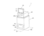
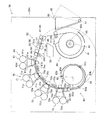
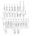
以下、本発明の好適な実施の形態について、図面を参照しつつ説明する。図1は、本発明の実施の形態に係るプリンタの外観斜視図である。図2は、図1のプリンタのプリント部(画像形成部)の概略構成を示す図である。図3は、図1のプリンタの搬送ローラ対及び送り込みローラ対の動きを表す図である。図4は、図1のプリンタの主要部及びこれらが接続された制御装置についてのブロック図である。   Hereinafter, preferred embodiments of the present invention will be described with reference to the drawings. FIG. 1 is an external perspective view of a printer according to an embodiment of the present invention. FIG. 2 is a diagram illustrating a schematic configuration of a printing unit (image forming unit) of the printer of FIG. FIG. 3 is a diagram illustrating the movement of the conveying roller pair and the feeding roller pair of the printer of FIG. FIG. 4 is a block diagram of a main part of the printer of FIG. 1 and a control device to which these are connected.

図1に示す熱昇華方式のサーマルプリンタ1(以下、「プリンタ1」と称する)は、操作部10と、制御装置20と、プリント部30とを有している。操作部10は、オペレータがプリンタ1に対する操作を行うものであって、プリンタ1に関する様々な情報を表示してオペレータに告知するディスプレイ11を有している。ここで、本実施の形態では、操作部10にはタッチパネル方式が採用されており、ディスプレイ10には様々なボタンを含む操作画面12が表示される。従って、オペレータは、操作画面12に触れることによってプリンタ1に対する操作を実行することができる。   A thermal sublimation thermal printer 1 shown in FIG. 1 (hereinafter referred to as “printer 1”) includes an operation unit 10, a control device 20, and a printing unit 30. The operation unit 10 is for an operator to operate the printer 1 and has a display 11 for displaying various information about the printer 1 and notifying the operator. Here, in the present embodiment, a touch panel method is adopted for the operation unit 10, and an operation screen 12 including various buttons is displayed on the display 10. Accordingly, the operator can execute an operation on the printer 1 by touching the operation screen 12.

制御装置20は、操作部10からの入力を受信すると共に、プリンタ1における各種の動作を制御するためのものである。また、制御装置20は、カードスロットやディスクドライブなどの種々の記憶媒体からプリントデータを取得するための複数のデータ入力部20aを有している。なお、記憶媒体としては、例えばCD−ROM、メモリーカードなど、プリントデータを記憶可能なものであればどのようなものであってもよい。   The control device 20 receives input from the operation unit 10 and controls various operations in the printer 1. In addition, the control device 20 has a plurality of data input units 20a for acquiring print data from various storage media such as a card slot and a disk drive. The storage medium may be any medium that can store print data, such as a CD-ROM or a memory card.

ここで、操作部10及び制御装置20は、プリント部30を収容する筐体30aの上面に固定配置されている。ここで、操作部10のディスプレイ11の表示面及び制御装置20のデータ入力部20aの記憶媒体挿入面は、プリンタ1(筐体30a)の正面(図1では左手前側の面)とほぼ一致している。従って、プリンタ1の正面に向かうオペレータにとって、ディスプレイ11及びデータ入力部20aに対する操作が行い易くなっている。   Here, the operation unit 10 and the control device 20 are fixedly arranged on the upper surface of the housing 30 a that houses the print unit 30. Here, the display surface of the display 11 of the operation unit 10 and the storage medium insertion surface of the data input unit 20a of the control device 20 substantially coincide with the front of the printer 1 (housing 30a) (the surface on the left front side in FIG. 1). ing. Therefore, it is easy for an operator heading to the front of the printer 1 to operate the display 11 and the data input unit 20a.

また、筐体30aは、略直方体形状を有しており、その横幅(正面の幅)D1は奥行きD2よりも小さくなっている。従って、プリンタ1は、横幅の比較的狭い空間においても設置することが可能である。さらに、筐体30aの正面には、筐体30a内に収納された後述するプリントボックス96を筐体30a外に引き出すための開口95が形成されている。   Moreover, the housing | casing 30a has a substantially rectangular parallelepiped shape, The horizontal width (front width) D1 is smaller than the depth D2. Therefore, the printer 1 can be installed even in a relatively narrow space. Furthermore, an opening 95 is formed on the front surface of the housing 30a for drawing out a print box 96 (described later) housed in the housing 30a to the outside of the housing 30a.

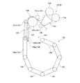
プリント部30は、図2に示すように、筐体30a内に、ロール状に巻回された用紙(記録媒体)を保持する用紙供給部(供給部)40と、用紙供給部40から巻き解かれた用紙を巻き取る用紙巻取部(格納部)80と、用紙供給部40と用紙巻取部80との間で、一方向に湾曲した搬送経路に沿って用紙を搬送可能な搬送機構38とを有している。また、用紙供給部40と用紙巻取部80との間には、搬送経路の上流側から下流側に向かって、切断部50、オーバーコート部60及び印字部(画像記録部)70が配置されている。また、用紙供給部40と切断部50との間の搬送経路近傍には、プリントボックス96が設けられている。   As shown in FIG. 2, the print unit 30 includes a paper supply unit (supply unit) 40 that holds a paper (recording medium) wound in a roll shape in the housing 30 a, and the paper supply unit 40 unwinds the paper. A paper take-up unit (storage unit) 80 that takes up the paper that has been taken up, and a conveyance mechanism 38 that can convey the paper along a conveyance path curved in one direction between the paper supply unit 40 and the paper take-up unit 80. And have. A cutting unit 50, an overcoat unit 60, and a printing unit (image recording unit) 70 are arranged between the paper supply unit 40 and the paper winding unit 80 from the upstream side to the downstream side of the conveyance path. ing. A print box 96 is provided near the conveyance path between the paper supply unit 40 and the cutting unit 50.

なお、本実施の形態では、「用紙の搬送方向(搬送方向)」とは、用紙供給部40から用紙巻取部80に向かう方向を意味するものとする。また、「用紙の先端部」及び「画像の先端部」とは、用紙または画像の搬送方向下流側の端部を意味するものとし、「用紙の後端部」及び「画像の後端部」とは、用紙または画像の搬送方向上流側の端部を意味するものとする。   In the present embodiment, “paper transport direction (transport direction)” means a direction from the paper supply unit 40 toward the paper winding unit 80. Further, the “paper front end” and the “image front end” mean the end on the downstream side of the paper or the image transport direction, and the “paper rear end” and “image rear end” The term “edge” means an end portion on the upstream side of the sheet or image in the conveying direction.

用紙供給部40は、搬送経路の最上流に設けられたマガジンケース41を有しており、その中には、長尺の用紙がその印字面が外側になるように回転軸43の周りに巻回された巻回部45が装填されている。ここで、回転軸43は、モータ43a(図4参照)によって、用紙供給部40から用紙が巻き解かれて搬送方向下流側に向かって搬送される場合には図2において反時計回りに回転駆動され、一旦巻き解かれた用紙が用紙供給部40に巻き取られる場合には図2において時計回りに回転駆動される。なお、回転軸43は、後述するワンウェイクラッチ34c、35cと同様の機能を有するワンウェイクラッチ43cを介して、モータ43aにより回転駆動されるシャフト(図示せず)と連結されている。   The paper supply unit 40 has a magazine case 41 provided in the uppermost stream of the transport path, and a long paper is wound around the rotation shaft 43 so that the printing surface is outside. The wound winding part 45 is loaded. Here, the rotating shaft 43 is driven to rotate counterclockwise in FIG. 2 when the sheet is unwound from the sheet supply unit 40 and conveyed toward the downstream side in the conveying direction by the motor 43a (see FIG. 4). When the unwound paper is taken up by the paper supply unit 40, it is rotated clockwise in FIG. The rotary shaft 43 is connected to a shaft (not shown) that is rotationally driven by a motor 43a via a one-way clutch 43c having the same function as one-way clutches 34c and 35c described later.

搬送機構38は、搬送方向上流側から順に配置されている、用紙供給部40の巻回部45から巻き解かれた用紙を上方に向かって搬送可能な給紙ローラ対31と、切断部50よりも搬送方向上流側に配置されており上方に向かって搬送される用紙の搬送方向を変更するターンローラ対32と、切断部50とオーバーコート部60との間において用紙を挟持可能な圧着ローラ対33及び用紙を搬送可能な搬送ローラ対34と、印字部70よりも搬送方向下流側に配置されており印字部70よりも搬送方向下流側に向かって搬送される用紙を用紙巻取部80の内部に送り込むための送り込みローラ対35とを有している。なお、本実施の形態では、給紙ローラ対31、ターンローラ対32、圧着ローラ対33、送り込みローラ対35は樹脂製のローラから構成されており、搬送ローラ対34は金属製のローラから構成されている。   The transport mechanism 38 is arranged in order from the upstream side in the transport direction, and includes a pair of paper feed rollers 31 that can transport the paper unrolled from the winding unit 45 of the paper supply unit 40 upward, and the cutting unit 50. Also, a turn roller pair 32 that is arranged on the upstream side in the transport direction and changes the transport direction of the paper transported upward, and a pressure roller pair that can sandwich the paper between the cutting unit 50 and the overcoat unit 60. 33 and a pair of transport rollers 34 capable of transporting the paper, and a paper which is disposed downstream of the printing unit 70 in the transport direction and transported downstream of the printing unit 70 in the transport direction. A feed roller pair 35 for feeding the inside is provided. In this embodiment, the paper feed roller pair 31, the turn roller pair 32, the pressure roller pair 33, and the feed roller pair 35 are made of resin rollers, and the transport roller pair 34 is made of a metal roller. Has been.

ここで、給紙ローラ対31、ターンローラ対32、圧着ローラ対33、搬送ローラ対34及び送り込みローラ対35は、所定半径を有する円周(図2では二点鎖線で描かれている)に沿うように配置されている。なお、図2から分かるように、オーバーコート部60及び印字部70のヘッド部61、71〜73も上記円周に沿うように配置されていると共に、用紙供給部40及び用紙巻取部80は上記円周の内部に配置されている。   Here, the pair of feed rollers 31, the pair of turn rollers 32, the pair of pressure rollers 33, the pair of transport rollers 34 and the pair of feed rollers 35 are arranged on a circumference having a predetermined radius (indicated by a two-dot chain line in FIG. 2). It is arranged along. As can be seen from FIG. 2, the head portions 61 and 71 to 73 of the overcoat portion 60 and the printing portion 70 are also arranged along the circumference, and the paper supply portion 40 and the paper take-up portion 80 are It arrange | positions inside the said periphery.

給紙ローラ対31、搬送ローラ対34及び送り込みローラ対35は、搬送制御部27a(図4参照)によって制御されるモータ31a、34a、35a(図4参照)にそれぞれ接続されており、回転駆動可能である。   The paper feed roller pair 31, the transport roller pair 34, and the feed roller pair 35 are connected to motors 31a, 34a, and 35a (see FIG. 4) controlled by the transport control unit 27a (see FIG. 4), respectively, and are rotationally driven. Is possible.

ここで、図3を用いて、搬送ローラ対34及び送り込みローラ対35の動きについて詳細に説明する。図3(a)は、用紙が搬送方向下流側に搬送される際の、搬送ローラ対34及び送り込みローラ対35の動きを表しており、図3(b)は、用紙が搬送方向上流側に逆送される際の、搬送ローラ対34及び送り込みローラ対35の動きを表している。図3に示すように、搬送ローラ対34は、駆動ローラ34dと従動ローラ34eとから構成されている。そして、駆動ローラ34dは、ワンウェイクラッチ34cを介して、モータ34aにより回転駆動されるシャフト34bと連結されている。同様に、送り込みローラ対35は、駆動ローラ35dと従動ローラ35eとから構成されており、駆動ローラ35dは、ワンウェイクラッチ35cを介して、モータ35aにより回転駆動されるシャフト35bと連結されている。   Here, the movement of the transport roller pair 34 and the feed roller pair 35 will be described in detail with reference to FIG. FIG. 3A shows the movement of the transport roller pair 34 and the feed roller pair 35 when the paper is transported downstream in the transport direction, and FIG. 3B shows that the paper is upstream in the transport direction. The movement of the conveying roller pair 34 and the feeding roller pair 35 during reverse feeding is shown. As shown in FIG. 3, the conveyance roller pair 34 includes a driving roller 34d and a driven roller 34e. The drive roller 34d is connected to a shaft 34b that is rotationally driven by a motor 34a via a one-way clutch 34c. Similarly, the feed roller pair 35 includes a drive roller 35d and a driven roller 35e, and the drive roller 35d is connected to a shaft 35b that is rotationally driven by a motor 35a via a one-way clutch 35c.

ワンウェイクラッチ34c、35cは、いずれも同様の機能を有しているので、ここではワンウェイクラッチ34cの機能について説明する。ワンウェイクラッチ34cは、駆動ローラ34dに固定されており、駆動ローラ34dと一体となって回転する。そして、駆動ローラ34dが、シャフト34bの回転速度よりも速く回転する場合には、シャフト34bの回転力は駆動ローラ34dに伝達されず、駆動ローラ34dはシャフト34bに対して空回りする。また、それ以外の場合には、シャフト34bの回転力がワンウェイクラッチ34cを介して駆動ローラ34dに伝達され、シャフト34bと駆動ローラ34dとが一体となって回転する。   Since the one-way clutches 34c and 35c have the same function, the function of the one-way clutch 34c will be described here. The one-way clutch 34c is fixed to the driving roller 34d and rotates together with the driving roller 34d. When the driving roller 34d rotates faster than the rotational speed of the shaft 34b, the rotational force of the shaft 34b is not transmitted to the driving roller 34d, and the driving roller 34d rotates idly with respect to the shaft 34b. In other cases, the rotational force of the shaft 34b is transmitted to the drive roller 34d via the one-way clutch 34c, and the shaft 34b and the drive roller 34d rotate together.

したがって、搬送ローラ対34が用紙を挟持している際に、用紙の搬送速度が、モータ34aによって駆動される搬送ローラ対34の回転力に基づく用紙の搬送速度よりも遅い場合には、モータ34aの駆動力が搬送ローラ対34に伝達される。そして、用紙は、搬送ローラ対34により与えられる搬送力で搬送される。一方、用紙の搬送速度が、モータ34aによって駆動される搬送ローラ対34の回転力に基づく用紙の搬送速度よりも速い場合には、モータ34aの駆動力は搬送ローラ対34に伝達されず、搬送ローラ対34は空回りする。つまり、搬送ローラ対34は、用紙の搬送速度に応じた回転数で従動回転する。   Therefore, when the conveyance roller pair 34 holds the sheet, the conveyance speed of the sheet is slower than the conveyance speed of the sheet based on the rotational force of the conveyance roller pair 34 driven by the motor 34a. Is transmitted to the conveying roller pair 34. Then, the sheet is transported with a transport force applied by the transport roller pair 34. On the other hand, when the paper conveyance speed is faster than the paper conveyance speed based on the rotational force of the conveyance roller pair 34 driven by the motor 34a, the driving force of the motor 34a is not transmitted to the conveyance roller pair 34 and is conveyed. The roller pair 34 is idle. That is, the transport roller pair 34 is driven to rotate at a rotational speed corresponding to the paper transport speed.

ここで、モータ34aによって駆動される搬送ローラ対34の回転力に基づく用紙の搬送速度をV1、モータ35aによって駆動される送り込みローラ対35の回転力に基づく用紙の搬送速度をV2とし、図3(a)を参照しつつ、用紙を搬送方向下流側に搬送する場合について考える。このとき、後述するように、用紙の先端部が送り込みローラ対35に到達して挟持されてからは、搬送ローラ対34の駆動が停止されるので、搬送速度V1は0となる。一方、送り込みローラ対35は、モータ35aの駆動力がシャフト35b及びワンウェイクラッチ35cを介して伝達されて回転駆動される。そして、搬送ローラ対34が挟持している用紙は、搬送速度V2で搬送されるようになるので、ワンウェイクラッチ34cの機能により、搬送ローラ対34は空回りする。   Here, the sheet conveying speed based on the rotational force of the conveying roller pair 34 driven by the motor 34a is V1, and the sheet conveying speed based on the rotational force of the feeding roller pair 35 driven by the motor 35a is V2. Consider the case of transporting a sheet downstream in the transport direction with reference to (a). At this time, as will be described later, after the leading edge of the paper reaches the feed roller pair 35 and is nipped, the drive of the transport roller pair 34 is stopped, and the transport speed V1 becomes zero. On the other hand, the feed roller pair 35 is rotationally driven by the driving force of the motor 35a being transmitted through the shaft 35b and the one-way clutch 35c. Since the sheet sandwiched between the transport roller pair 34 is transported at the transport speed V2, the transport roller pair 34 is idled by the function of the one-way clutch 34c.

次に、図3(b)を参照しつつ、用紙を搬送方向上流側に逆送する場合について考える。このとき、後述するように、送り込みローラ対35の駆動が停止されるので、搬送速度V2は0となる。一方、搬送ローラ対34は、モータ34aの駆動力がシャフト34b及びワンウェイクラッチ34cを介して伝達されて回転駆動される。そして、送り込みローラ対35が挟持している用紙は、搬送速度V1で逆送されるようになるので、ワンウェイクラッチ35cの機能により、送り込みローラ対35は空回りする。   Next, with reference to FIG. 3B, consider a case where the paper is fed back upstream in the transport direction. At this time, as will be described later, since the driving of the feed roller pair 35 is stopped, the conveyance speed V2 becomes zero. On the other hand, the conveying roller pair 34 is rotationally driven by the driving force of the motor 34a being transmitted through the shaft 34b and the one-way clutch 34c. Since the sheet sandwiched between the feed roller pair 35 is reversely fed at the conveyance speed V1, the feed roller pair 35 rotates idly by the function of the one-way clutch 35c.

また、給紙ローラ対31についても、上述のワンウェイクラッチ34c、35cと同様の機能を有するワンウェイクラッチ31cを介して、モータ31aにより回転駆動されるシャフト(図示せず)と連結されている。従って、給紙ローラ対31、搬送ローラ対34及び送り込みローラ対35は、搬送制御部27aによってモータ31a、34a、35aが個別に制御されることによって、用紙供給部40から巻き解かれた用紙を搬送方向下流側に向かって搬送して用紙巻取部80に巻き取り可能であると共に、用紙巻取部80内に一旦巻き取られた用紙を再度巻き解きつつ、用紙巻取部80から巻き解かれた用紙を搬送方向上流側に向かって逆送させることができる。即ち、搬送機構38によって、用紙を印字部70に対向させつつ用紙供給部40から印字部70に向かう第1の方向(用紙の搬送方向)と、この第1の方向とは反対方向である第2の方向(搬送方向に対する逆送方向)とに搬送可能となっている。   The pair of paper feed rollers 31 is also connected to a shaft (not shown) that is rotationally driven by a motor 31a via a one-way clutch 31c having the same function as the one-way clutches 34c and 35c described above. Accordingly, the paper feed roller pair 31, the transport roller pair 34, and the feed roller pair 35 are configured to remove the paper unrolled from the paper supply unit 40 by individually controlling the motors 31a, 34a, and 35a by the transport control unit 27a. The sheet can be conveyed downstream in the conveying direction and taken up by the paper take-up unit 80, and the paper once taken up in the paper take-up unit 80 can be unwound and unwound from the paper take-up unit 80. The printed paper can be fed back toward the upstream side in the transport direction. That is, the first direction (paper transport direction) from the paper supply unit 40 toward the print unit 70 while the paper is opposed to the print unit 70 by the transport mechanism 38 is opposite to the first direction. It can be conveyed in the direction of 2 (the reverse direction with respect to the conveyance direction).

また、プリント部30は、搬送ローラ対34の回転数を検出可能なエンコーダ36を有している。ここで、上述したように、搬送ローラ対34は、用紙を搬送するためにモータ34aにより駆動されて回転する状態と、送り込みローラ対35により搬送される用紙に伴って従動回転する状態とを取り得る。エンコーダ36は、搬送ローラ34が上記のいずれの状態である場合でも、搬送ローラ対34の回転数を検出することができる。   Further, the printing unit 30 includes an encoder 36 that can detect the number of rotations of the conveyance roller pair 34. Here, as described above, the transport roller pair 34 is driven and rotated by the motor 34a to transport the paper, and is driven and rotated along with the paper transported by the feed roller pair 35. obtain. The encoder 36 can detect the number of rotations of the conveyance roller pair 34 even when the conveyance roller 34 is in any of the above states.

切断部50は、ターンローラ対32と圧着ローラ対33との間に配置されている。切断部50は、搬送経路よりも上方に配置されたローリングカッタ51と、搬送経路よりも下方に配置された固定刃52と、切りくずボックス53とを有している。   The cutting part 50 is disposed between the turn roller pair 32 and the pressure roller pair 33. The cutting unit 50 includes a rolling cutter 51 disposed above the conveyance path, a fixed blade 52 disposed below the conveyance path, and a chip box 53.

ローリングカッタ51は、円板形状を有しており、その円周部には全周にわたって刃が形成されている。そして、ローリングカッタ51は、その中心部がシャフト51aで保持されている。ローリングカッタ51は、シャフト51aを介して、切断制御部27cによって制御される駆動機構55(図4参照)に接続されている。駆動機構55は、シャフト51aを介して、ローリングカッタ51を回転駆動する共に、用紙の搬送経路を直交する方向に沿って(図2では紙面に直交する方向に沿って)往動または復動させる。一方、固定刃52は、用紙の搬送経路に直交するように配置されており、用紙の搬送経路の全幅よりも長い矩形刃である。   The rolling cutter 51 has a disk shape, and a blade is formed on the entire circumference of the rolling cutter 51. The center of the rolling cutter 51 is held by a shaft 51a. The rolling cutter 51 is connected to a drive mechanism 55 (see FIG. 4) controlled by the cutting control unit 27c via a shaft 51a. The drive mechanism 55 rotates and drives the rolling cutter 51 via the shaft 51a, and moves forward or backward along the sheet conveyance path along a direction orthogonal to the sheet (in the direction orthogonal to the paper surface in FIG. 2). . On the other hand, the fixed blade 52 is a rectangular blade that is disposed so as to be orthogonal to the paper transport path and is longer than the entire width of the paper transport path.

従って、切断部50による切断位置に用紙が配置された状態において、切断制御部27cが駆動機構55を制御して、ローリングカッタ51を回転させつつ用紙の幅方向に沿って移動させると、ローリングカッタ51と固定刃52との相互作用によって用紙が切断される。なお、本実施の形態のプリンタ1では、後述するように切断部50は各画像の先端部及び後端部において用紙を切断する。   Therefore, when the cutting control unit 27c controls the drive mechanism 55 and moves the rolling cutter 51 along the width direction of the paper while rotating the paper while the paper is arranged at the cutting position by the cutting unit 50, the rolling cutter The sheet is cut by the interaction between 51 and the fixed blade 52. In the printer 1 according to the present embodiment, as will be described later, the cutting unit 50 cuts the paper at the leading edge and the trailing edge of each image.

また、切りくずボックス53は、ローリングカッタ51及び固定刃52の下方に配置されている。従って、各画像の先端部または後端部において用紙が切断されて各画像間の余白部が切断されると、その余白部は切りくずボックス53内に収納される。   The chip box 53 is disposed below the rolling cutter 51 and the fixed blade 52. Accordingly, when the paper is cut at the leading edge or the trailing edge of each image and the blank portion between the images is cut, the blank portion is stored in the chip box 53.

オーバーコート部60は、搬送ローラ対34の搬送方向下流側に配置されている。オーバーコート部60は、1つのヘッド部61を有している。ヘッド部61は、画像が印字された用紙の表面に対して無色透明なオーバーコート(OC)を行うためのものである。このように、用紙の表面に対してオーバーコートを行うことによって、用紙上に印字された画像の耐光性が向上すると共に、用紙表面を保護することができる。また、オーバーコートの材質を選ぶことで、プリントの光沢性が向上し、高品質のプリントを提供することができる。   The overcoat unit 60 is disposed on the downstream side of the conveyance roller pair 34 in the conveyance direction. The overcoat part 60 has one head part 61. The head unit 61 is for performing a colorless and transparent overcoat (OC) on the surface of the paper on which an image is printed. Thus, by overcoating the surface of the paper, the light resistance of the image printed on the paper can be improved and the surface of the paper can be protected. Further, by selecting the material of the overcoat, the gloss of the print can be improved and a high-quality print can be provided.

また、印字部70は、オーバーコート部60と送り込みローラ対35との間に配置されている。印字部70は、3つのヘッド部71〜73を有している。ヘッド部71〜73は、それぞれシアン(C)、マゼンタ(M)、イエロー(Y)に対応する印字を行うためのものである。ここで、プリンタ1では、搬送方向上流側から搬送方向下流側に向かって、シアンに対応するヘッド部71、マゼンタに対応するヘッド部72、イエローに対応するヘッド部73の順に設けられている。なお、プリンタ1では、オーバーコート部60及び印字部70の搬送方向上流側に搬送ローラ対34が配置されており、それらの搬送方向下流側に送り込みローラ対35が配置されていることになる。   The printing unit 70 is disposed between the overcoat unit 60 and the feed roller pair 35. The printing unit 70 has three head units 71 to 73. The head portions 71 to 73 are for performing printing corresponding to cyan (C), magenta (M), and yellow (Y), respectively. Here, in the printer 1, a head unit 71 corresponding to cyan, a head unit 72 corresponding to magenta, and a head unit 73 corresponding to yellow are provided in this order from the upstream side in the transport direction to the downstream side in the transport direction. In the printer 1, the transport roller pair 34 is disposed on the upstream side in the transport direction of the overcoat unit 60 and the printing unit 70, and the feed roller pair 35 is disposed on the downstream side in the transport direction.

そして、本実施の形態のプリンタ1では、用紙供給部40から巻き解かれた用紙が搬送方向下流側に向かって搬送されるときはオーバーコート部60でのオーバーコート及び印字部70でのカラー画像の印字は行われないで、印字部70よりも搬送方向下流側に配置された用紙巻取部80に一旦巻き取られた用紙が搬送方向上流側に向かって逆送されるときに印字部70での画像の印字及びオーバーコート部60でのオーバーコートが行われる。従って、プリンタ1では、用紙表面に対して、イエロー、マゼンタ、シアンの順にカラー画像の印字が可能であると共に、さらに、カラー画像が印字された用紙表面に対してオーバーコートを行うことができる。   In the printer 1 of the present embodiment, when the paper unrolled from the paper supply unit 40 is conveyed toward the downstream side in the conveyance direction, the overcoat in the overcoat unit 60 and the color image in the printing unit 70 are performed. Is not performed, and when the paper once wound on the paper take-up unit 80 disposed on the downstream side in the transport direction from the print unit 70 is fed back toward the upstream side in the transport direction, the print unit 70 The printing of the image at and the overcoat at the overcoat unit 60 are performed. Accordingly, the printer 1 can print a color image in the order of yellow, magenta, and cyan on the paper surface, and can further overcoat the paper surface on which the color image is printed.

次に、ヘッド部61、71〜73の概略構成について説明する。なお、ヘッド部61、71〜73の構成はいずれも同様であるので、ここではヘッド部73についてのみ詳細に説明する。   Next, a schematic configuration of the head units 61 and 71 to 73 will be described. In addition, since the structure of the head parts 61 and 71 to 73 is the same, only the head part 73 will be described in detail here.

ヘッド部73は、用紙の搬送経路の全幅にわたって配置された多数の発熱素子(図示しない)を有するサーマルヘッド73aと、サーマルヘッド73aの先端部(用紙の搬送経路近傍であって発熱素子が配置された端部)に対向するプラテンローラ73bと、イエローに対応するインクが付着したインク領域を有するテープ状のリボン73cと、印字前のリボン73cが巻回されたリボン供給ローラ73dと、印字後のリボン73cを巻き取るリボン巻取ローラ73eとを有している。   The head unit 73 includes a thermal head 73a having a large number of heating elements (not shown) arranged over the entire width of the paper conveyance path, and a tip portion of the thermal head 73a (in the vicinity of the paper conveyance path and the heating elements are arranged). A platen roller 73b facing the other end, a tape-like ribbon 73c having an ink area to which ink corresponding to yellow is attached, a ribbon supply roller 73d around which a ribbon 73c before printing is wound, and a post-printing ribbon A ribbon take-up roller 73e for taking up the ribbon 73c.

ここで、サーマルヘッド73aは、昇降機構73f(図4参照)によって、用紙の搬送経路に対して進退可能になっている。従って、サーマルヘッド73aは、その先端部近傍とプラテンローラ73bとの間で、リボン73c及び用紙を圧接するプリント位置と圧接しない待避位置とを選択的に取り得る。   Here, the thermal head 73a can be moved back and forth with respect to the paper transport path by an elevating mechanism 73f (see FIG. 4). Therefore, the thermal head 73a can selectively take the print position where the ribbon 73c and the paper are pressed against each other and the retracted position where the paper 73 is not pressed between the vicinity of the tip and the platen roller 73b.

そして、ヘッド部73では、サーマルヘッド73aがプリント位置に配置されている状態で、サーマルヘッド73aとプラテンローラ73bとの間を用紙が搬送されると、サーマルヘッド73aにより加熱されたリボン73cのインクによって用紙上にイエローに対応するカラー画像を印字することができる。なお、このとき、サーマルヘッド73aとプラテンローラ73bとの間を用紙が搬送される際には、用紙が搬送されるのに伴ってリボン73cもリボン供給ローラ73dからリボン巻取ローラ73eに向かって送られる。   In the head unit 73, when the paper is conveyed between the thermal head 73a and the platen roller 73b in a state where the thermal head 73a is disposed at the printing position, the ink of the ribbon 73c heated by the thermal head 73a. Thus, a color image corresponding to yellow can be printed on the paper. At this time, when the sheet is conveyed between the thermal head 73a and the platen roller 73b, the ribbon 73c is also moved from the ribbon supply roller 73d toward the ribbon take-up roller 73e as the sheet is conveyed. Sent.

なお、ヘッド部61及びヘッド部71、72は、ヘッド部73と同様に、サーマルヘッド61a、71a、72aと、プラテンローラ61b、71b、72bと、リボン61c、71c、72cと、リボン供給ローラ61d、71d、72dと、リボン巻取ローラ61e、71e、72eと、昇降機構61f、71f、72fとをそれぞれ備えている。   The head unit 61 and the head units 71 and 72 are similar to the head unit 73 in that the thermal heads 61a, 71a, 72a, the platen rollers 61b, 71b, 72b, the ribbons 61c, 71c, 72c, and the ribbon supply roller 61d. 71d, 72d, ribbon take-up rollers 61e, 71e, 72e, and elevating mechanisms 61f, 71f, 72f, respectively.

ここで、ヘッド部61及びヘッド部71、72では、ヘッド部73のイエローに対応するインクが付着したインク領域を有するテープ状のリボン73cの代わりに、無色透明、シアン、マゼンタにそれぞれ対応するインクが付着したインク領域を有するテープ状のリボン61c、71c、72cが用いられている。   Here, in the head unit 61 and the head units 71 and 72, ink corresponding to colorless and transparent, cyan and magenta, respectively, instead of the tape-like ribbon 73c having an ink region to which ink corresponding to yellow of the head unit 73 is attached. Tape-shaped ribbons 61c, 71c, and 72c having an ink region to which are attached are used.

また、オーバーコート部60のヘッド部61及び印字部70の各ヘッド部71〜73間には、一対のガイド75a〜75cがそれぞれ配置されている。一対のガイド75a〜75cは、いずれも2枚の板状部材を含んでおり、ヘッド部61、71〜73間をそれぞれ搬送される用紙(主に用紙の先端部)を案内するためのものである。従って、一対のガイド75a〜75cは、用紙の搬送経路を挟んで所定間隔を隔てて対向するように配置されている。   A pair of guides 75 a to 75 c are arranged between the head portion 61 of the overcoat portion 60 and the head portions 71 to 73 of the printing portion 70, respectively. Each of the pair of guides 75a to 75c includes two plate-like members, and guides the sheet (mainly the leading end of the sheet) conveyed between the head units 61 and 71 to 73, respectively. is there. Accordingly, the pair of guides 75a to 75c are arranged so as to face each other with a predetermined interval across the sheet conveyance path.

用紙巻取部80は、搬送経路の最下流に設けられた格納ケース81を有しており、印字部70に対して用紙供給部40とは反対側にある用紙の一部を格納することが可能となっている。格納ケース81は、略円筒形状を有しており、その一部が用紙の挿入口82として開口している。即ち、搬送方向に搬送されてきた用紙は、挿入口82を通じて用紙巻取部80へと格納されるようになっている。なお、本実施の形態では、図2に示すように、挿入口82となる部分(記録媒体受け入れ開口部分)の中心角は約90度であって、その一方の縁部82aは格納ケース81の左端部近傍にあって、他方の縁部82bは格納ケース81の上端部近傍にある。   The paper take-up unit 80 has a storage case 81 provided on the most downstream side of the transport path, and can store a part of the paper on the opposite side of the print unit 70 from the paper supply unit 40. It is possible. The storage case 81 has a substantially cylindrical shape, and a part of the storage case 81 opens as a paper insertion opening 82. That is, the sheet conveyed in the conveying direction is stored in the sheet take-up unit 80 through the insertion port 82. In the present embodiment, as shown in FIG. 2, the central angle of the portion (recording medium receiving opening portion) that becomes the insertion opening 82 is about 90 degrees, and one edge portion 82a of the portion 82a of the storage case 81 is formed. Near the left end, the other edge 82 b is near the upper end of the storage case 81.

また、格納ケース81の一方の端部82aは、送り込みローラ対35のすぐ下流側の近くまで延在するように設けられており、この端部82aによって、用紙が用紙巻取部80内に格納されるように、搬送方向に搬送される用紙を挿入口82において誘導する誘導機構が構成されている。即ち、印字部70の下流側で送り込みローラ対35から下方に送り出された用紙は、送り込みローラ対35の下流側に近接した格納ケース81の端部82aに沿って挿入口82に挿入され、そのまま格納ケース81内へと誘導されることになる。このように、誘導機構を構成する端部82aを設けることで、記録用紙を用紙巻取部80に格納する際に、詰まりや搬送経路からの脱落等の搬送トラブルを発生させることなくこの記録用紙を適正に搬送することができる。   Further, one end portion 82a of the storage case 81 is provided so as to extend to a position near the downstream side of the feeding roller pair 35, and the sheet is stored in the paper take-up portion 80 by this end portion 82a. As described above, a guiding mechanism for guiding the sheet conveyed in the conveying direction at the insertion port 82 is configured. That is, the sheet fed downward from the feeding roller pair 35 on the downstream side of the printing unit 70 is inserted into the insertion port 82 along the end 82a of the storage case 81 adjacent to the downstream side of the feeding roller pair 35, and remains as it is. It will be guided into the storage case 81. As described above, by providing the end portion 82a constituting the guide mechanism, when recording paper is stored in the paper take-up unit 80, the recording paper does not cause a transport trouble such as clogging or dropping off from the transport path. Can be transported properly.

なお、挿入口82を通じて用紙巻取部80に挿入された用紙は、格納ケース81の内周壁面に沿って誘導されて格納ケース81の内部に案内される。その結果、格納ケース81内では、用紙が有する巻き癖にしたがって、その印字面が外側面になるように(即ち、用紙供給部40で外側面であった面が外側面となるように)用紙の先端部から順に巻き取られる。   The paper inserted into the paper take-up unit 80 through the insertion opening 82 is guided along the inner peripheral wall surface of the storage case 81 and guided into the storage case 81. As a result, in the storage case 81, according to the curl of the paper, the printing surface becomes the outer surface (that is, the surface that was the outer surface in the paper supply unit 40 becomes the outer surface). Are wound in order from the tip.

また、用紙巻取部80の格納ケース81には、回転自在に支持された4つの巻き取りローラ(ローラ、回転体)83a〜83dが設けられている。この巻き取りローラ83a〜83dは、格納ケース81の内周壁面の周方向に沿って設けられるとともに、その一部が格納ケース81の内周壁面よりも内側に突出している。即ち、巻き取りローラ83a〜83dは、搬送方向に搬送される用紙が格納ケース81内において巻回されつつ格納されるように誘導される誘導経路に沿って複数配置されているとともに、この誘導経路を横断する方向であってこの誘導経路に平行な軸の周りに回転自在に支持されている。このように、巻き取りローラ83a〜83dを設けることで、搬送方向に搬送される用紙を格納ケース81の内周壁面に沿って滞りなく搬送でき、用紙を格納ケース81内にて詰まり等の搬送トラブルの発生を抑制しつつスムーズに巻回しながら格納することができる。また、格納ケース81の内周壁面に沿って配置された巻き取りローラ83a〜83dにより搬送方向における摩擦抵抗が軽減されるため、記録用紙の表面が疵付いてしまうことを抑制できる。   The storage case 81 of the paper winding unit 80 is provided with four winding rollers (rollers, rotating bodies) 83a to 83d that are rotatably supported. The take-up rollers 83 a to 83 d are provided along the circumferential direction of the inner peripheral wall surface of the storage case 81, and a part of the take-up rollers 83 a to 83 d protrudes inward from the inner peripheral wall surface of the storage case 81. That is, the take-up rollers 83a to 83d are arranged in a plurality along the guide path that guides the sheet transported in the transport direction to be stored while being wound in the storage case 81. And is supported rotatably about an axis parallel to the guide path. In this way, by providing the take-up rollers 83a to 83d, the paper conveyed in the conveyance direction can be conveyed without any delay along the inner peripheral wall surface of the storage case 81, and the paper can be conveyed in the storage case 81 such as a jam. It is possible to store while smoothly winding while suppressing the occurrence of trouble. In addition, since the frictional resistance in the transport direction is reduced by the take-up rollers 83a to 83d arranged along the inner peripheral wall surface of the storage case 81, it is possible to suppress the surface of the recording paper from becoming wrinkled.

プリントボックス96は、印字部70における画像の印字及びオーバーコート部60におけるオーバーコートが行われた後、さらに切断部50によって切断された各カラー画像が印字された用紙(プリント)を排出するためのものである。また、プリントボックス96は、上端部が開口された箱状の部材であって、その下端部において支持軸97によって回動可能に支持されている。従って、プリントボックス96は、筐体30a内に収納された状態(図2で実線で示す状態)と、筐体30aの正面(図2では右面)に設けられた開口95を介してその上端部近傍が筐体30a外に引き出された状態(図2で破線で示す状態)とを取り得る。よって、オペレータは、プリントボックス96の上端部をプリンタ1(筐体30a)の正面から外部に引き出すことによって、各カラー画像が印字された用紙を容易に取り出すことができる。   The print box 96 is for discharging the paper (print) on which each color image printed by the cutting unit 50 is printed after the image is printed in the printing unit 70 and the overcoat unit 60 is overcoated. Is. The print box 96 is a box-shaped member having an upper end opened, and is supported by a support shaft 97 at the lower end to be rotatable. Accordingly, the print box 96 has a state in which the print box 96 is housed in the housing 30a (shown by a solid line in FIG. 2) and an upper end portion of the print box 96 through the opening 95 provided on the front surface (right surface in FIG. 2). A state in which the vicinity is pulled out of the housing 30a (a state indicated by a broken line in FIG. 2) can be taken. Therefore, the operator can easily take out the paper on which each color image is printed by pulling out the upper end portion of the print box 96 from the front of the printer 1 (housing 30a).

なお、プリントボックス96の上方には、ターンローラ対32よりも搬送方向上流側の搬送経路に近接するように振り分け機構(図示しない)が設けられている。この振り分け機構は、用紙が用紙供給部40に巻き取られる場合と、各カラー画像が印字された用紙がプリントボックス96に排出される場合とで、用紙が搬送方向上流側に向かって逆送される際の用紙の搬送経路を切り換えることができる。従って、振り分け機構を制御することによって、各カラー画像が印字された用紙だけをプリントボックス96内に収納することができる。   A sorting mechanism (not shown) is provided above the print box 96 so as to be close to the transport path upstream of the turn roller pair 32 in the transport direction. In this sorting mechanism, the paper is fed back toward the upstream side in the transport direction when the paper is wound around the paper supply unit 40 and when the paper on which each color image is printed is discharged to the print box 96. It is possible to switch the paper transport path when printing. Therefore, by controlling the sorting mechanism, only the paper on which each color image is printed can be stored in the print box 96.

また、切断部50よりも搬送方向上流側には、搬送経路に沿って搬送される用紙上に印字された画像の端部(主に画像の後端部)を検出可能な画像検出センサ90が設けられている。一方、オーバーコート部60よりも搬送方向上流側には、用紙の端部を検出可能な用紙検出センサ91が設けられている。なお、本実施の形態では、オーバーコート部60の搬送方向上流側の端部と用紙検出センサ91による検出位置とはほぼ一致している。   Further, an image detection sensor 90 that can detect an end portion (mainly a rear end portion of the image) of an image printed on a sheet conveyed along the conveyance path, on the upstream side of the cutting unit 50 in the conveyance direction. Is provided. On the other hand, a paper detection sensor 91 that can detect the edge of the paper is provided upstream of the overcoat unit 60 in the transport direction. In the present embodiment, the end of the overcoat unit 60 on the upstream side in the conveyance direction and the detection position by the paper detection sensor 91 substantially coincide.

制御装置20には、図4に示すように、用紙供給部40の回転軸43を駆動するモータ43aと、給紙ローラ対31、搬送ローラ対34及び送り込みローラ対35をそれぞれ駆動するモータ31a、34a、35aと、搬送ローラ対34の回転数を検出するエンコーダ36と、切断部50のローリングカッタ51の駆動機構55と、オーバーコート部60及び印字部70のサーマルヘッド61a、71a〜73aの昇降機構61f、71f〜73f及びドライバ61g、71g〜73gと、画像検出センサ90と、用紙検出センサ91と、操作部10とがそれぞれ接続されている。   As shown in FIG. 4, the control device 20 includes a motor 43 a that drives the rotation shaft 43 of the paper supply unit 40, a motor 31 a that drives the paper feed roller pair 31, the transport roller pair 34, and the feed roller pair 35, respectively. 34a, 35a, an encoder 36 for detecting the rotation speed of the conveying roller pair 34, a driving mechanism 55 for the rolling cutter 51 of the cutting unit 50, and the thermal heads 61a, 71a to 73a of the overcoat unit 60 and the printing unit 70. The mechanisms 61f and 71f to 73f and the drivers 61g and 71g to 73g, the image detection sensor 90, the paper detection sensor 91, and the operation unit 10 are respectively connected.

また、制御装置20は、適切なソフトウェアにより制御されるCPUやROM、RAMなどのハードウェアを備えており、最大巻取量記憶部21と、プリント情報記憶部22と、必要巻取量算出部23と、比較部24と、巻取量決定部25と、搬送量検知部26と、搬送制御部27aと、印字制御部27bと、切断制御部27cとを有している。   The control device 20 includes hardware such as a CPU, a ROM, and a RAM controlled by appropriate software, and includes a maximum winding amount storage unit 21, a print information storage unit 22, and a necessary winding amount calculation unit. 23, a comparison unit 24, a winding amount determination unit 25, a conveyance amount detection unit 26, a conveyance control unit 27a, a print control unit 27b, and a cutting control unit 27c.

最大巻取量記憶部21は、用紙供給部40から用紙巻取部80に向かって用紙が搬送される場合に、印字部70よりも搬送方向下流側に搬送可能な用紙の最大長さを最大巻取量として記憶する。この最大巻取量は、印字部70の搬送方向について最も下流側に配置されたヘッド部73による印字位置と用紙巻取部80の挿入口82との間の搬送経路の長さと、用紙巻取部80の格納ケース81内に巻き取り可能な用紙の長さとを足し合わせることによって算出される値である。なお、最大巻取量は、オペレータによって最大巻取量記憶部21に対して入力される。   The maximum winding amount storage unit 21 maximizes the maximum length of paper that can be transported downstream in the transport direction from the printing unit 70 when the paper is transported from the paper supply unit 40 toward the paper winding unit 80. It is memorized as a winding amount. The maximum winding amount is determined by the length of the conveyance path between the printing position by the head unit 73 arranged on the most downstream side in the conveyance direction of the printing unit 70 and the insertion port 82 of the sheet winding unit 80, and the sheet winding. This value is calculated by adding together the length of paper that can be taken up in the storage case 81 of the unit 80. The maximum winding amount is input to the maximum winding amount storage unit 21 by the operator.

ここで、最大巻取量は、主として格納ケース81の大きさによって大きく変化する。なお、格納ケース81内に巻き取り可能な用紙の長さは、実際に格納ケース81内に収容可能な用紙の最大長さであってもよいし、格納ケース81内に収容可能な用紙の最大長さより短くてもよく、任意に設定可能である。そこで、本実施の形態では、最大巻取量が算出される際に用いられる格納ケース81内に巻き取り可能な用紙の長さは、格納ケース81内において用紙が破損したり疵が付いたりしない範囲の長さであって、格納ケース81内に収容可能な用紙の最大長さよりは短い長さが設定されている。   Here, the maximum winding amount largely varies depending on the size of the storage case 81. The length of paper that can be wound in the storage case 81 may be the maximum length of paper that can actually be stored in the storage case 81, or the maximum length of paper that can be stored in the storage case 81. It may be shorter than the length and can be set arbitrarily. Therefore, in the present embodiment, the length of the paper that can be wound in the storage case 81 used when the maximum winding amount is calculated is that the paper is not damaged or wrinkled in the storage case 81. The length of the range is set to be shorter than the maximum length of paper that can be stored in the storage case 81.

プリント情報記憶部22は、カラー画像が印字される際の種々の設定値を記憶する。ここで、設定値としては、プリント種類毎の1コマのプリント長さ(搬送方向長さ)、プリント枚数(コマ数)、隣り合う画像間に形成される余白部の長さ、ヘッド放熱用の追加長さなどが含まれる。プリント種類毎の1コマのプリント長さは、例えば標準サイズ、パノラマサイズなどの複数のプリントの種類毎に複数の値が記憶されている。プリント枚数は、プリント開始前に、オペレータによってオーダー毎に入力される値が記憶される。また、画像間の余白部の長さ及びヘッド放熱用の追加長さは、プリント開始前に、オペレータによって入力される値が記憶される。なお、追加長さは、画像を印字するために発熱したサーマルヘッド71a、72a、73a及び、オーバーコートを行うために発熱したサーマルヘッド61aの温度が、通電終了後にその周囲温度と実質的に同じになるまで用紙が各サーマルヘッド61a、71a〜73aと対向しているような長さに設定されている。本実施の形態では、発熱した各サーマルヘッド61a、71a〜73aが、いずれもその周囲温度と実質的に同じになるまでに必要な時間と、搬送方向上流側に向かって逆送される用紙の搬送速度との積によって追加長さが算出される。   The print information storage unit 22 stores various setting values when a color image is printed. Here, the set values include the print length of one frame for each print type (the length in the transport direction), the number of prints (the number of frames), the length of the margin formed between adjacent images, and the head heat dissipation. Includes additional length. As the print length of one frame for each print type, a plurality of values are stored for each of a plurality of print types such as a standard size and a panorama size. As the number of prints, a value input for each order by the operator before printing is stored. Further, the length of the margin between the images and the additional length for heat radiation of the head are stored as values input by the operator before starting printing. The additional length is such that the temperatures of the thermal heads 71a, 72a, 73a that have generated heat for printing an image and the thermal head 61a that has generated heat for overcoating are substantially the same as the ambient temperature after energization. The sheet is set to such a length that the sheet faces each of the thermal heads 61a and 71a to 73a. In the present embodiment, the time required for each of the thermal heads 61a, 71a to 73a that have generated heat to be substantially the same as the ambient temperature, and the sheet to be fed back toward the upstream side in the transport direction. The additional length is calculated by the product with the conveyance speed.

ここで、「1オーダー」とは、プリンタ1において複数のカラー画像が記録される場合に1つのまとまりとして取り扱われる範囲を示すものである。例えば、プリンタ1において、一人の顧客からの注文に対応する複数のカラー画像が1つのまとまりとして取り扱われるときには、この一人の顧客からの注文が1オーダーとなる。一方、複数人の顧客からの注文に対応する複数のカラー画像が1つのまとまりとして取り扱われるときには、これらの複数人の顧客からの注文があわせて1オーダーとなる。なお、上述のように顧客ごとの注文の1又は複数が1オーダーとなる場合の他、オペレータがプリンタ1に対して複数のカラー画像を記録する旨のプリント命令を供給する場合には、そのプリント命令が1オーダーとなる。従って、「1オーダーに含まれる複数のカラー画像」とは、上述のように顧客ごとの注文の1又は複数が1オーダーとなる場合は、その1又は複数の注文に含まれる複数のカラー画像を意味し、オペレータがプリンタ1に対して複数のカラー画像を記録する旨のプリント命令を供給する場合は、そのプリント命令に基づいて記録される複数のカラー画像を意味する。   Here, “one order” indicates a range that is handled as one unit when a plurality of color images are recorded in the printer 1. For example, in the printer 1, when a plurality of color images corresponding to an order from one customer are handled as one unit, the order from this one customer is one order. On the other hand, when a plurality of color images corresponding to orders from a plurality of customers are handled as one unit, the orders from these plurality of customers are combined into one order. In addition to the case where one or a plurality of orders for each customer is one order as described above, when the operator supplies a print command to the printer 1 to record a plurality of color images, the print The order is one order. Therefore, “a plurality of color images included in one order” means that when one or more orders for each customer are one order as described above, a plurality of color images included in the one or more orders. That is, when the operator supplies a print command for recording a plurality of color images to the printer 1, it means a plurality of color images recorded based on the print command.

必要巻取量算出部23は、1オーダーに含まれる複数のカラー画像の全てを印字するために必要な用紙の長さを必要巻取量として算出する。つまり、1オーダーに含まれる複数のカラー画像の全てを印字するためには、印字部70でのカラー画像の印字を開始する前に、これらのカラー画像を印字可能な長さの用紙を印字部70よりも搬送方向下流側に搬送しておく必要がある。従って、用紙供給部40から用紙巻取部80に向かって用紙が搬送される場合に、1オーダーに含まれる複数のカラー画像の全てを印字するために、印字部70のヘッド部73による印字位置を超えて搬送されるべき用紙の長さが必要巻取量として算出される。   The necessary winding amount calculation unit 23 calculates the length of paper necessary for printing all of a plurality of color images included in one order as the necessary winding amount. In other words, in order to print all of a plurality of color images included in one order, before the printing of the color image by the printing unit 70, paper having a length capable of printing these color images is printed on the printing unit. It is necessary to carry the sheet downstream in the carrying direction from 70. Therefore, when the paper is conveyed from the paper supply unit 40 toward the paper take-up unit 80, the printing position by the head unit 73 of the printing unit 70 is used to print all of the plurality of color images included in one order. The length of the paper to be transported exceeding this is calculated as the required winding amount.

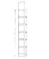
ここで、必要巻取量について、図5を参照して説明する。図5は、1オーダーに含まれる複数のカラー画像が用紙の先端部近傍に印字されるときの様子を示す図である。なお、図5では、1オーダーには同じプリント種類の画像が6個含まれる場合について図示している。図5に示すように、用紙の先端(図5では左端部)近傍にヘッド放熱用の追加長さzに対応する領域が設けられ、そこから上流側(図5では右方)に向かって、プリント長さxに対応する領域と余白部長さyに対応する領域がプリント枚数nだけ交互に設けられる。   Here, the necessary winding amount will be described with reference to FIG. FIG. 5 is a diagram illustrating a state in which a plurality of color images included in one order are printed in the vicinity of the leading edge of the paper. Note that FIG. 5 illustrates a case where six images of the same print type are included in one order. As shown in FIG. 5, a region corresponding to the additional length z for heat radiation of the head is provided near the leading end (left end portion in FIG. 5) of the sheet, and from there toward the upstream side (right side in FIG. 5) The area corresponding to the print length x and the area corresponding to the margin length y are alternately provided by the number n of prints.

従って、必要巻取量算出部23では、プリント開始前に、オペレータによって、1オーダーに含まれるカラー画像のプリント種類及びプリント枚数が入力されると、プリント情報記憶部22に記憶された各値に基づいて、1オーダーに対応する必要巻取量Lが下記の式によって算出される。
L=z+x×n+y×(n−1)
Accordingly, in the necessary winding amount calculation unit 23, when the print type and the number of prints of a color image included in one order are input by the operator before starting printing, each value stored in the print information storage unit 22 is set. Based on this, the required winding amount L corresponding to one order is calculated by the following equation.
L = z + x * n + y * (n-1)

比較部24は、必要巻取量算出部23で算出された必要巻取量と最大巻取量記憶部21に記憶された最大巻取量とを比較する。そして、比較部24は、必要巻取量と最大巻取量との間の大小関係についての比較結果を得る。   The comparison unit 24 compares the required winding amount calculated by the required winding amount calculation unit 23 with the maximum winding amount stored in the maximum winding amount storage unit 21. Then, the comparison unit 24 obtains a comparison result regarding the magnitude relationship between the required winding amount and the maximum winding amount.

巻取量決定部25は、用紙の搬送方向が搬送方向下流側に向かう方向から搬送方向上流側に向かう方向に変更される前に、実際に印字部70よりも搬送方向下流側に搬送される用紙の長さ(実際の巻取量)、すなわち、実際に印字部70のヘッド部73に対向する位置を超えて搬送される用紙の長さを決定する。ここで、巻取量決定部25は、比較部24による比較結果に基づいて巻取量を決定する。つまり、巻取量決定部25は、比較部24において必要巻取量が最大巻取量以下であるという比較結果が得られた場合は、実際の巻取量を必要巻取量に決定し、一方、比較部24において必要巻取量が最大巻取量より長いという比較結果が得られた場合は、実際の巻取量を最大巻取量に決定する。   The winding amount determination unit 25 is actually transported downstream of the printing unit 70 in the transport direction before the sheet transport direction is changed from the direction toward the downstream side in the transport direction to the direction toward the upstream side in the transport direction. The length of the sheet (actual winding amount), that is, the length of the sheet that is actually conveyed beyond the position facing the head unit 73 of the printing unit 70 is determined. Here, the winding amount determination unit 25 determines the winding amount based on the comparison result by the comparison unit 24. That is, when the comparison unit 24 obtains a comparison result that the required winding amount is equal to or less than the maximum winding amount, the winding amount determination unit 25 determines the actual winding amount as the necessary winding amount, On the other hand, when the comparison unit 24 obtains a comparison result that the required winding amount is longer than the maximum winding amount, the actual winding amount is determined as the maximum winding amount.

搬送量検知部26は、用紙検出センサ91によって用紙の先端が検出された後にエンコーダ36により検出される搬送ローラ対34の回転数に基づいて、用紙の搬送量を検知する。つまり、搬送量検知部26は、用紙検出センサ91による検出位置よりも搬送方向下流側に搬送された用紙の長さを検知する。その結果、搬送量検知部26は、用紙の搬送方向が搬送方向下流側に向かう方向から搬送方向上流側に向かう方向に変更される前に、印字部70よりも搬送方向下流側に搬送された用紙の長さを検知することができる。なお、後述するように、用紙の先端部が送り込みローラ対35に到達した後は、搬送ローラ対34から与えられる搬送力ではなく送り込みローラ対35から与えられる搬送力によって用紙が搬送されるようになるが、この場合でも、搬送量検知部26では、常に搬送ローラ対34の回転数に基づいて用紙の搬送量が検知される。   The carry amount detection unit 26 detects the carry amount of the paper based on the number of rotations of the carry roller pair 34 detected by the encoder 36 after the leading edge of the paper is detected by the paper detection sensor 91. That is, the transport amount detection unit 26 detects the length of the paper transported downstream in the transport direction from the position detected by the paper detection sensor 91. As a result, the transport amount detection unit 26 is transported downstream of the printing unit 70 in the transport direction before the sheet transport direction is changed from the direction toward the downstream side in the transport direction to the direction toward the upstream side in the transport direction. The length of the paper can be detected. As will be described later, after the leading edge of the sheet reaches the feed roller pair 35, the sheet is transported by the transport force applied from the feed roller pair 35 instead of the transport force applied from the transport roller pair 34. However, even in this case, the carry amount detection unit 26 always detects the carry amount of the paper based on the number of rotations of the carry roller pair 34.

搬送量検知部26は、用紙が搬送方向下流側に向かって搬送される場合だけでなく、用紙が搬送方向上流側に向かって搬送される場合にも、用紙の搬送量を検知することができる。従って、用紙の搬送方向が搬送方向下流に向かう方向から搬送方向上流に向かう方向に変更された場合には、搬送方向が変更される前の搬送方向下流側への搬送量から、搬送方向が変更された後の搬送方向上流側への搬送量を差し引くことによって、用紙の先端位置を検知することができる。   The conveyance amount detection unit 26 can detect the conveyance amount of the paper not only when the paper is conveyed toward the downstream side in the conveyance direction but also when the paper is conveyed toward the upstream side in the conveyance direction. . Therefore, when the paper transport direction is changed from the direction downstream in the transport direction to the direction upstream in the transport direction, the transport direction is changed from the transport amount downstream in the transport direction before the transport direction is changed. The leading end position of the sheet can be detected by subtracting the transport amount upstream in the transport direction after being performed.

搬送制御部27aは、回転軸43、給紙ローラ対31、搬送ローラ対34及び送り込みローラ対35を駆動するモータ43a、31a、34a、35aを制御することによって、用紙を用紙供給部40から用紙巻取部80に向かって搬送すると共に、用紙を用紙巻取部80から用紙供給部40に向かって逆送させる。   The conveyance control unit 27a controls the motors 43a, 31a, 34a, and 35a that drive the rotation shaft 43, the paper feed roller pair 31, the conveyance roller pair 34, and the feeding roller pair 35, thereby supplying the paper from the paper supply unit 40 to the paper. The sheet is conveyed toward the winding unit 80 and the sheet is fed back from the sheet winding unit 80 toward the sheet supply unit 40.

ここで、搬送制御部27aの機能をより詳細に説明する。まず、用紙を搬送方向下流側に向かって搬送する際に、用紙の先端部が搬送ローラ対34を通過して用紙検出センサ91に到達するまでは、モータ34aの駆動を停止させると共に、回転軸43の回転力に基づく用紙の送り出し速度に比べて、給紙ローラ対31の回転力に基づく用紙の搬送速度が速くなるようにモータ43a、31aを制御する。このとき、ワンウェイクラッチ43c、31c、34cの機能により、回転軸43及び搬送ローラ対34は空回りし、給紙ローラ対31はモータ31aによって駆動される。したがって、用紙は、給紙ローラ対31から与えられる搬送力によって搬送される。   Here, the function of the conveyance control unit 27a will be described in more detail. First, when the sheet is conveyed toward the downstream side in the conveyance direction, the driving of the motor 34a is stopped and the rotation shaft is stopped until the leading edge of the sheet passes through the conveyance roller pair 34 and reaches the sheet detection sensor 91. The motors 43a and 31a are controlled so that the paper transport speed based on the rotational force of the paper feed roller pair 31 is faster than the paper feed speed based on the rotational force 43. At this time, due to the functions of the one-way clutches 43c, 31c, and 34c, the rotating shaft 43 and the conveyance roller pair 34 are idle, and the paper feed roller pair 31 is driven by the motor 31a. Accordingly, the sheet is transported by the transport force applied from the pair of sheet feed rollers 31.

その後、用紙の先端部が送り込みローラ対35に挟持されるまでは、モータ43a、31aの駆動を停止し、モータ34aのみを駆動する。このとき、ワンウェイクラッチ43c、31c、34cの機能により、回転軸43及び給紙ローラ対31は空回りし、搬送ローラ対34はモータ34aによって駆動される。したがって、用紙は、搬送ローラ対34から与えられる搬送力のみによって搬送される。   Thereafter, the motors 43a and 31a are stopped driving until only the motor 34a is driven until the leading edge of the sheet is nipped by the feed roller pair 35. At this time, due to the functions of the one-way clutches 43c, 31c, and 34c, the rotating shaft 43 and the paper feed roller pair 31 are idle, and the transport roller pair 34 is driven by the motor 34a. Accordingly, the sheet is transported only by the transport force applied from the transport roller pair 34.

そして、用紙の先端部が送り込みローラ対35に挟持されると、モータ43a、31a、34aの駆動を停止し、モータ35aのみを駆動する。このとき、ワンウェイクラッチ43c、31c、34c、35cの機能により、回転軸43、給紙ローラ対31及び搬送ローラ対34は空回りし、送り込みローラ対35はモータ35aによって駆動される。したがって、用紙は、搬送ローラ対35から与えられる搬送力のみによって搬送される。   When the leading edge of the sheet is sandwiched between the feed roller pair 35, the motors 43a, 31a and 34a are stopped and only the motor 35a is driven. At this time, due to the functions of the one-way clutches 43c, 31c, 34c, and 35c, the rotary shaft 43, the paper feed roller pair 31, and the transport roller pair 34 are idle, and the feed roller pair 35 is driven by the motor 35a. Accordingly, the sheet is transported only by the transport force applied from the transport roller pair 35.

また、用紙を搬送方向上流側に向かって逆送する際に、用紙の最も搬送方向上流側に印字されるカラー画像の後端部が切断されるまでは、モータ35aの駆動を停止すると共に、回転軸43の回転力に基づく用紙の巻き戻し速度、給紙ローラ対31の回転力に基づく用紙の搬送速度、及び搬送ローラ対34の回転力に基づく用紙の搬送速度が等しくなるようにモータ43a、31a、34aを制御する。このとき、ワンウェイクラッチ43c、31c、34c、35cの機能により、回転軸43、給紙ローラ対31及び搬送ローラ対34はそれぞれモータ43a、31a、34aによって駆動され、送り込みローラ対35は空回りする。したがって、用紙は、回転軸43、給紙ローラ対31及び搬送ローラ対34から与えられる搬送力で逆送される。   Further, when the paper is fed back toward the upstream side in the transport direction, the driving of the motor 35a is stopped until the rear end portion of the color image printed on the most upstream side in the transport direction of the paper is cut. The motor 43a is configured such that the sheet rewinding speed based on the rotational force of the rotating shaft 43, the paper conveying speed based on the rotational force of the paper feed roller pair 31, and the paper conveying speed based on the rotational force of the conveying roller pair 34 are equal. , 31a, 34a are controlled. At this time, due to the functions of the one-way clutches 43c, 31c, 34c, and 35c, the rotating shaft 43, the paper feed roller pair 31, and the transport roller pair 34 are driven by the motors 43a, 31a, and 34a, respectively, and the feed roller pair 35 rotates idle. Therefore, the sheet is fed back by the conveying force applied from the rotating shaft 43, the sheet feeding roller pair 31 and the conveying roller pair 34.

そして、用紙の最も搬送方向上流側に印字されるカラー画像の後端部が切断された後、回転軸43の回転力に基づく用紙の巻き戻し速度、給紙ローラ対31の回転力に基づく用紙の搬送速度が等しくなるようにモータ43a、31aを制御することで、ワンウェイクラッチ43c、31cの機能により、回転軸43及び給紙ローラ対31がモータ43a、31aによって駆動されるようにし、搬送方向について切断位置よりも上流側の用紙を用紙供給部40に巻き戻す。また、モータ34aを駆動し、モータ35aの駆動を停止することで、ワンウェイクラッチ34c、35cの機能により、搬送ローラ対34をモータ34aによって駆動させ、送り込みローラ対35を空回りさせる。したがって、搬送方向について切断位置よりも下流側の用紙は、搬送ローラ対34から与えられる搬送力だけで逆送される。   Then, after the trailing edge of the color image printed on the most upstream side in the transport direction of the paper is cut, the paper is rewound based on the rotational force of the rotary shaft 43 and the paper is based on the rotational force of the paper feed roller pair 31. By controlling the motors 43a and 31a so that the conveyance speeds of the two are equal, the function of the one-way clutches 43c and 31c allows the rotation shaft 43 and the paper feed roller pair 31 to be driven by the motors 43a and 31a, and the conveyance direction. The paper upstream of the cutting position is rewound to the paper supply unit 40. Further, by driving the motor 34a and stopping the driving of the motor 35a, the transport roller pair 34 is driven by the motor 34a and the feed roller pair 35 is idled by the function of the one-way clutches 34c and 35c. Accordingly, the sheet on the downstream side of the cutting position in the transport direction is reversely fed only by the transport force applied from the transport roller pair 34.

印字制御部27bは、オーバーコート部60のサーマルヘッド61a及び印字部70のサーマルヘッド71a〜73aの昇降タイミング及び印字タイミングを制御する。詳細には、印字制御部27bは、用紙が搬送方向下流側に搬送される際には、サーマルヘッド61a、71a〜73aを退避位置とし、用紙が搬送方向上流側に逆送される前に、サーマルヘッド61a、71a〜73aをプリント位置とするように昇降タイミングを制御する。また、印字制御部27bは、搬送方向上流側に逆送されている用紙に対して、1オーダーに含まれる複数のカラー画像が余白部の長さ分だけ隔ててそれぞれ印字され、且つ、最後に印字されたカラー画像よりも用紙の先端部側の追加長さに対応する領域には画像が印字されないように印字タイミングを制御する。さらに、印字制御部27bは、用紙のカラー画像が印字された領域のみにオーバーコートを行うようにオーバーコート部60を制御する。   The printing control unit 27b controls the raising / lowering timing and printing timing of the thermal head 61a of the overcoat unit 60 and the thermal heads 71a to 73a of the printing unit 70. Specifically, when the paper is transported downstream in the transport direction, the print control unit 27b sets the thermal heads 61a and 71a to 73a to the retracted position, and before the paper is fed back upstream in the transport direction, The raising / lowering timing is controlled so that the thermal heads 61a, 71a to 73a are set to the printing positions. In addition, the print control unit 27b prints a plurality of color images included in one order separated by the length of the blank portion on the paper that has been fed back upstream in the transport direction, and finally, The printing timing is controlled so that the image is not printed in an area corresponding to the additional length on the leading end side of the paper than the printed color image. Further, the print control unit 27b controls the overcoat unit 60 so as to overcoat only the area where the color image of the paper is printed.

切断制御部27cは、切断部50での切断タイミングを制御する。詳細には、切断制御部27cは、搬送量検知部26によって検知される、用紙の搬送方向が搬送方向下流に向かう方向から搬送方向上流に向かう方向に変更された後の搬送方向上流側への用紙の搬送量に基づいて、最も搬送方向上流側に印字されたカラー画像の後端部が、切断部50による切断位置に到達したことを検知し、そのカラー画像の後端部が切断されるように切断部50を制御する。また、切断制御部27cは、搬送量検知部26によって検知される、画像検出センサ90において画像の後端部が検出された後の搬送方向上流側への用紙の搬送量に基づいて、カラー画像の先端部が、切断部50による切断位置に到達したことを検知し、そのカラー画像の先端部が切断されるように切断部50を制御する。さらに、切断制御部27cは、搬送量検知部26によって検知される、カラー画像の先端部での用紙の切断が行われた後の搬送方向上流側への用紙の搬送量に基づいて、搬送方向下流側において隣接するカラー画像の後端部が、切断部50による切断位置に到達したことを検知し、そのカラー画像の後端部が切断されるように切断部50を制御する。   The cutting control unit 27 c controls the cutting timing at the cutting unit 50. In detail, the cutting control unit 27c detects the conveyance amount detection unit 26 to the upstream side in the conveyance direction after the sheet conveyance direction is changed from the direction toward the downstream in the conveyance direction to the direction toward the upstream in the conveyance direction. Based on the transport amount of the paper, it is detected that the rear end portion of the color image printed most upstream in the transport direction has reached the cutting position by the cutting unit 50, and the rear end portion of the color image is cut. Thus, the cutting unit 50 is controlled. Further, the cutting control unit 27c detects the color image based on the conveyance amount of the sheet upstream in the conveyance direction after the trailing edge of the image is detected by the image detection sensor 90, which is detected by the conveyance amount detection unit 26. Is detected to have reached the cutting position by the cutting unit 50, and the cutting unit 50 is controlled so that the leading end of the color image is cut. Further, the cutting control unit 27c detects the conveyance direction based on the conveyance amount upstream of the conveyance direction after the sheet is cut at the leading end of the color image, which is detected by the conveyance amount detection unit 26. It is detected that the rear end of the color image adjacent on the downstream side has reached the cutting position by the cutting unit 50, and the cutting unit 50 is controlled so that the rear end of the color image is cut.

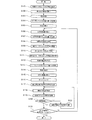
次に、プリンタ1において、画像の印字が行われる際の動作について、図6を参照して説明する。図6は、プリンタ1での動作手順を示すフローチャートである。   Next, the operation when the printer 1 prints an image will be described with reference to FIG. FIG. 6 is a flowchart showing an operation procedure in the printer 1.

まず、用紙供給部40に装填された用紙の巻回部45から回転軸43が回転駆動されることによって巻き解かれた用紙の先端部が、給紙ローラ対31から与えられる搬送力だけによって搬送される(ステップS101)。そして、用紙の先端部が搬送ローラ対34を通過して用紙検出センサ91に到達するまで給紙ローラ対31による搬送が継続される(ステップS102)。ここで、用紙検出センサ91により用紙の先端部が検出されると、用紙検出センサ91から制御装置20に対して用紙の先端部を検出した旨の検出信号が送信される。   First, the leading end of the sheet unwound by rotating the rotary shaft 43 from the paper winding unit 45 loaded in the paper supply unit 40 is transported only by the transport force applied from the paper feed roller pair 31. (Step S101). Then, the conveyance by the paper feed roller pair 31 is continued until the leading edge of the paper passes through the conveyance roller pair 34 and reaches the paper detection sensor 91 (step S102). Here, when the leading edge of the sheet is detected by the sheet detection sensor 91, a detection signal indicating that the leading edge of the sheet has been detected is transmitted from the sheet detection sensor 91 to the control device 20.

このようにして、用紙の先端部が用紙検出センサ91に到達した時点で、用紙の搬送が停止されて待機状態になる(ステップS103)。このとき、サーマルヘッド61a、71a〜73aがプリント位置に配置されている場合は、サーマルヘッド61a、71a〜73aが待避位置に移動させられる(ステップS104)。   In this way, when the leading edge of the paper reaches the paper detection sensor 91, the conveyance of the paper is stopped and a standby state is entered (step S103). At this time, if the thermal heads 61a and 71a to 73a are arranged at the print positions, the thermal heads 61a and 71a to 73a are moved to the retracted positions (step S104).

その後、オペレータからの注文(オーダー)の受付があって、1オーダーに含まれるカラー画像のプリント種類及びプリント枚数が入力されると(ステップS105)、用紙の搬送を開始する準備として、プリント情報記憶部22に記憶された情報に基づいて、その1オーダーに対応する必要巻取量が必要巻取量算出部23によって算出される(ステップS106)。すると、比較部24によって、この必要巻取量と最大巻取量記憶部21に記憶された最大巻取量とが比較される(ステップS107)。その比較結果に基づいて、巻取量決定部25によって、実際の巻取量が決定される(ステップS108)。このようにして、用紙の搬送準備が終了した後で、搬送ローラ対34から与えられる搬送力だけによって用紙が搬送される(ステップS109)。なお、このとき、用紙供給部40の回転軸43及び給紙ローラ対31はいずれも回転自在になっている。   Thereafter, when an order is received from the operator and the print type and the number of prints of color images included in one order are input (step S105), the print information is stored as preparation for starting the conveyance of the paper. Based on the information stored in the unit 22, the necessary winding amount corresponding to the one order is calculated by the necessary winding amount calculation unit 23 (step S106). Then, the required winding amount is compared with the maximum winding amount stored in the maximum winding amount storage unit 21 by the comparison unit 24 (step S107). Based on the comparison result, the winding amount determination unit 25 determines the actual winding amount (step S108). In this way, after completion of the sheet conveyance preparation, the sheet is conveyed only by the conveyance force applied from the conveyance roller pair 34 (step S109). At this time, both the rotation shaft 43 and the paper feed roller pair 31 of the paper supply unit 40 are rotatable.

その後、サーマルヘッド61a、71a〜73aが待避位置に配置された状態において、用紙の先端部が、オーバーコート部60及び印字部70をオーバーコート及び画像の印字が行われないまま通過して送り込みローラ対35に到達するまで、搬送ローラ対34から与えられる搬送力だけによって搬送が継続される(ステップS110)。そして、用紙の先端部が送り込みローラ対35に到達して挟持されるようになると、それ以後は送り込みローラ対35から与えられる搬送力だけによって用紙が搬送されて、用紙の先端部から用紙巻取部80の格納ケース81内に順次送り込まれる(ステップS111)。このとき、用紙が格納ケース81内に送り込まれるにつれて、用紙の先端部が格納ケース81の内周面及び巻き取りローラ83a〜83dに案内されて、格納ケース81内において、用紙がその巻き癖にしたがって巻き取られる。なお、用紙の先端部が送り込みローラ対35に到達した時点で、搬送ローラ対34は、ワンウェイクラッチ34cの機能により、用紙に搬送力を与える状態から送り込みローラ対35により搬送される用紙に伴って従動回転する状態に切り換えられる。   Thereafter, in a state in which the thermal heads 61a and 71a to 73a are disposed at the retracted positions, the leading end of the sheet passes through the overcoat unit 60 and the print unit 70 without performing overcoat and image printing, and the feed roller The conveyance is continued only by the conveyance force applied from the conveyance roller pair 34 until the pair 35 is reached (step S110). When the leading edge of the sheet reaches the nipping roller pair 35 and is nipped, the sheet is thereafter conveyed only by the conveying force applied from the feeding roller pair 35 and is wound from the leading edge of the sheet. Are sequentially fed into the storage case 81 of the unit 80 (step S111). At this time, as the paper is fed into the storage case 81, the leading edge of the paper is guided to the inner peripheral surface of the storage case 81 and the take-up rollers 83 a to 83 d, and the paper is wound around the curl in the storage case 81. Therefore, it is wound up. When the leading edge of the paper reaches the feed roller pair 35, the transport roller pair 34 is accompanied by the paper transported by the feed roller pair 35 from the state in which the transport force is applied to the paper by the function of the one-way clutch 34c. It is switched to the state of driven rotation.

その後、巻取量決定部25で決定された巻取量の長さの用紙が、ヘッド部73による印字位置よりも搬送方向下流側に搬送された時点で、用紙の巻き取りが終了して、用紙供給部40から用紙巻取部80に向かって用紙が搬送されるのが停止される(ステップS112)。つまり、搬送量検知部26において、用紙検出センサ91によって用紙の先端部が検出された後にエンコーダ36により検出される搬送ローラ対34の回転数に基づいて検知される用紙の搬送量が、巻取量決定部25で決定された巻取量と、オーバーコート部60及び印字部70における搬送経路の長さとを足し合わせた長さに一致した時点で、搬送制御部27aは用紙の巻き取りを終了し、用紙の搬送方向下流側への搬送を停止する。なお、このとき、ヘッド部73による印字位置には、巻取量の長さの用紙の最も搬送方向上流側に印字される画像の後端部が配置されている。   Thereafter, when the sheet having the length of the winding amount determined by the winding amount determination unit 25 is conveyed downstream in the conveyance direction from the printing position by the head unit 73, the winding of the sheet is finished, The conveyance of the sheet from the sheet supply unit 40 toward the sheet winding unit 80 is stopped (step S112). That is, the conveyance amount of the paper detected by the conveyance amount detection unit 26 based on the number of rotations of the conveyance roller pair 34 detected by the encoder 36 after the leading edge of the paper is detected by the paper detection sensor 91 is taken up. When the winding amount determined by the amount determination unit 25 and the length of the conveyance path in the overcoat unit 60 and the printing unit 70 are added, the conveyance control unit 27a finishes winding the sheet. Then, the conveyance of the sheet to the downstream side in the conveyance direction is stopped. At this time, the rear end portion of the image printed on the most upstream side in the transport direction of the sheet having the winding amount is disposed at the printing position by the head unit 73.

そして、オーバーコート部60のサーマルヘッド61a及び印字部70のサーマルヘッド71a〜73aが待避位置からプリント位置に同時に移動させられる(ステップS113)。その後、給紙ローラ対31及び搬送ローラ対34から与えられる搬送力によって用紙が搬送方向上流側に向かって逆送される(ステップS114)。従って、このとき、従動回転する状態であった給紙ローラ対31及び搬送ローラ対34は、用紙を搬送方向上流側に向かって搬送する方向に回転駆動されると共に、送り込みローラ対35は、ワンウェイクラッチ35cの機能により、従動回転するようになる。また、用紙供給部40の回転軸43はマガジンケース41内に用紙を巻き戻す方向に回転駆動される。   Then, the thermal head 61a of the overcoat unit 60 and the thermal heads 71a to 73a of the printing unit 70 are simultaneously moved from the retracted position to the printing position (step S113). Thereafter, the sheet is fed back toward the upstream side in the transport direction by the transport force applied from the pair of paper feed rollers 31 and the pair of transport rollers 34 (step S114). Accordingly, at this time, the pair of paper feed rollers 31 and the pair of transport rollers 34 that have been driven to rotate are rotationally driven in the direction of transporting paper toward the upstream side in the transport direction, and the pair of feed rollers 35 The function of the clutch 35c causes the driven rotation. Further, the rotation shaft 43 of the paper supply unit 40 is rotationally driven in a direction to rewind the paper into the magazine case 41.

そして、用紙が搬送方向上流側に向かって逆送されながら、1オーダーに含まれる各カラー画像について、ヘッド部73によってイエローに対応する印字、ヘッド部72によってマゼンタに対応する印字、ヘッド部71によってシアンに対応する印字が順次行われる。このようにして、各カラー画像について、イエロー、マゼンタ、シアンの順に印字が行われることによってカラー画像が完成する(ステップS115)。その後、引き続き、ヘッド部61によって、カラー画像が印字された用紙の表面に対してオーバーコートが行われる(ステップS116)。   Then, while the paper is being fed back toward the upstream side in the transport direction, for each color image included in one order, printing corresponding to yellow is performed by the head unit 73, printing corresponding to magenta is performed by the head unit 72, and printing is performed by the head unit 71. Printing corresponding to cyan is sequentially performed. In this way, each color image is printed in the order of yellow, magenta, and cyan, thereby completing the color image (step S115). After that, the head unit 61 continues to overcoat the surface of the paper on which the color image is printed (step S116).

なお、本実施の形態では、必要巻取量が最大巻取量よりも短い場合には、用紙の搬送方向上流側への逆送が開始されると同時に、カラー画像の印字が開始され、1オーダーに含まれるカラー画像の全てが各画像間に所定幅の余白部が形成されるように断続的に印字される。一方、必要巻取量が最大巻取量よりも長い場合には、用紙の搬送方向上流側への逆送が開始されると同時に、カラー画像の印字が開始され、1オーダーに含まれるカラー画像の一部が各画像間に所定幅の余白部が形成されるように断続的に印字される。つまり、上述したように、用紙には、画像領域と余白部とが交互に配置されるようにカラー画像が印字される。ただし、用紙先端近傍のヘッド放熱用の追加長さに対応する領域には画像は印字されない。そして、印字部70では、3つのヘッド部71〜73のうちの少なくとも2つに対向する位置に同じタイミングで画像領域がある場合には、それらのヘッド部によって同時に印字が行われる。また、オーバーコート部60でのオーバーコートは、印字部70でのカラー画像の印字と並行して行われる。このようにして、印字部70及びオーバーコート部60では、巻取量決定部25により決定された巻取量の長さの用紙または最大巻取量の長さの用紙に対して印字可能な複数のカラー画像についての印字及びオーバーコートが行われる。   In the present embodiment, when the necessary winding amount is shorter than the maximum winding amount, reverse feeding to the upstream side in the sheet conveyance direction is started, and simultaneously printing of a color image is started. All of the color images included in the order are printed intermittently so that a margin of a predetermined width is formed between the images. On the other hand, when the necessary winding amount is longer than the maximum winding amount, the reverse feeding to the upstream side in the sheet conveyance direction is started, and at the same time, the printing of the color image is started, and the color image included in one order. Are intermittently printed so that a margin of a predetermined width is formed between the images. That is, as described above, a color image is printed on the paper so that the image areas and the margins are alternately arranged. However, no image is printed in an area corresponding to the additional length for heat radiation near the leading edge of the paper. And in the printing part 70, when there exists an image area | region at the same timing in the position facing at least 2 of the three head parts 71-73, printing is simultaneously performed by those head parts. In addition, the overcoat in the overcoat unit 60 is performed in parallel with the printing of the color image in the print unit 70. In this way, in the printing unit 70 and the overcoat unit 60, a plurality of printable sheets can be printed on the paper having the winding amount determined by the winding amount determination unit 25 or the paper having the maximum winding amount. The color image is printed and overcoated.

最も搬送方向上流側に印字されたカラー画像の後端部(巻取量決定部25で決定された巻取量の長さの用紙の後端部と一致している)が、切断部50による切断位置に到達すると、用紙の逆送が停止され、そのカラー画像の後端部で用紙が切断される(ステップS117)。なお、カラー画像の後端部が切断部50による切断位置に到達するタイミングは、搬送量検知部26によって検知される搬送量に基づいて検知される。このように用紙が切断された後、最も搬送方向上流側のカラー画像よりも上流側の画像が形成されなかった用紙(巻取量決定部25で決定された巻取量の長さの用紙の後端部よりも搬送方向上流側の用紙)は、用紙供給部40に巻き戻される。   The trailing end of the color image printed on the most upstream side in the transport direction (corresponding to the trailing end of the sheet having the winding amount determined by the winding amount determination unit 25) is formed by the cutting unit 50. When the cutting position is reached, the reverse feeding of the paper is stopped, and the paper is cut at the rear end portion of the color image (step S117). Note that the timing at which the trailing edge of the color image reaches the cutting position by the cutting unit 50 is detected based on the carry amount detected by the carry amount detection unit 26. After the paper is cut in this way, the paper on which the image upstream of the most upstream color image in the transport direction is not formed (the paper of the length of the winding amount determined by the winding amount determination unit 25) The sheet on the upstream side in the transport direction from the rear end portion is rewound to the sheet supply unit 40.

引き続き、搬送ローラ対34から与えられる搬送力のみで用紙が逆送されて、最も搬送方向上流側の画像の後端部が画像検出センサ90による検出位置に到達すると、画像検出センサ90から制御装置20に対して画像の後端部を検出した旨の検出信号が送信される(ステップS118)。すると、搬送量検知部26は、画像検出センサ90によって画像の後端部が検出された後に、エンコーダ36により検出される搬送ローラ対34の回転数に基づいて、搬送方向上流側への用紙の搬送量を検知する。そして、その搬送量に基づいて、切断制御部27cにより、カラー画像の先端部が切断部50による切断位置に到達したことが検知される。このとき、用紙の逆送が停止され、カラー画像の先端部で用紙が切断される(ステップS119)。このように、カラー画像の先端部及び後端部を切断された用紙は、プリントボックス96に収納される。   Subsequently, when the sheet is reversely fed only by the conveyance force applied from the conveyance roller pair 34 and the rear end portion of the image on the most upstream side in the conveyance direction reaches the detection position by the image detection sensor 90, the image detection sensor 90 controls the control device. A detection signal indicating that the rear end of the image has been detected is transmitted to 20 (step S118). Then, the conveyance amount detection unit 26 detects the trailing edge of the image by the image detection sensor 90, and then detects the amount of the sheet upstream in the conveyance direction based on the number of rotations of the conveyance roller pair 34 detected by the encoder 36. Detect the transport amount. Based on the transport amount, the cutting control unit 27c detects that the leading end of the color image has reached the cutting position by the cutting unit 50. At this time, the reverse feeding of the paper is stopped, and the paper is cut at the leading end of the color image (step S119). In this way, the paper from which the leading edge and trailing edge of the color image are cut is stored in the print box 96.

カラー画像の先端部での用紙の切断が行われる度に、切断された用紙に印字されたカラー画像が用紙の先端部に最も近接して印字された最終画像であるか否かが判断される(ステップS120)。ここで、最終画像でないと判断されると、再び用紙が逆送される。すると、搬送量検知部26は、カラー画像の先端部での用紙の切断が行われた後、エンコーダ36により検出される搬送ローラ対34の回転数に基づいて、搬送方向上流側への用紙の搬送量を検知する。そして、切断制御部27cでは、その搬送量に基づいて、ステップS119で先端部が切断されたカラー画像と搬送方向下流側において隣接するカラー画像の後端部が、切断部50による切断位置に到達したことを検知する。このとき、用紙の逆送が停止され、そのカラー画像の後端部で用紙が切断される(ステップS121)。その後、ステップS118に戻って、上述と同様の処理が繰り返される。   Each time the paper is cut at the leading edge of the color image, it is determined whether the color image printed on the cut paper is the final image printed closest to the leading edge of the paper. (Step S120). Here, if it is determined that the image is not the final image, the paper is reversely fed again. Then, the conveyance amount detection unit 26 cuts the sheet at the leading end of the color image, and then, based on the number of rotations of the conveyance roller pair 34 detected by the encoder 36, the conveyance amount upstream of the conveyance direction is detected. Detect the transport amount. In the cutting control unit 27c, based on the conveyance amount, the rear end portion of the color image adjacent to the color image whose leading end portion was cut in step S119 on the downstream side in the conveyance direction reaches the cutting position by the cutting unit 50. Detecting that At this time, the reverse feeding of the paper is stopped, and the paper is cut at the rear end portion of the color image (step S121). Then, it returns to step S118 and the process similar to the above is repeated.

一方、最終画像であると判断されると、1オーダーに含まれるカラー画像の全ての印字が終了したか否かが判断される(ステップS122)。ここで、1オーダーに含まれるカラー画像の全ての印字が終了していないと判断されると、ステップS106に戻って、上述と同様の処理が繰り返される。一方、1オーダーに含まれるカラー画像の全ての印字が終了したと判断されると、処理が終了する。   On the other hand, if it is determined that the image is the final image, it is determined whether or not printing of all color images included in one order has been completed (step S122). If it is determined that printing of all the color images included in one order has not been completed, the process returns to step S106 and the same processing as described above is repeated. On the other hand, when it is determined that all the printing of the color images included in one order has been completed, the process ends.

なお、ステップS122で、1オーダーに含まれるカラー画像の全ての印字が終了していないと判断される場合とは、例えば比較部24において必要巻取量が最大巻取量より長いと判断されて、巻取量決定部25が最大巻取量を最終的な巻取量として決定した場合である。つまり、この場合には、1オーダーに含まれるカラー画像のなかで最大巻取量の長さの用紙に印字することができなかった残りのカラー画像の印字が引き続き行われる。このようにして、1オーダーに含まれるカラー画像の全ての印字が終了するまで、上述と同様の処理が繰り返される。   Note that the case where it is determined in step S122 that all printing of color images included in one order has not been completed means that, for example, the comparison unit 24 determines that the necessary winding amount is longer than the maximum winding amount. This is a case where the winding amount determination unit 25 determines the maximum winding amount as the final winding amount. That is, in this case, printing of the remaining color images that could not be printed on the sheet having the maximum winding amount among the color images included in one order is continued. In this way, the same processing as described above is repeated until all the printing of the color images included in one order is completed.

以上のように、本実施の形態のプリンタ1では、用紙供給部40から用紙巻取部80に向かう方向に用紙を搬送した後で、オーバーコート部60及び印字部70よりも搬送方向上流側に配置された搬送ローラ対34による搬送力によって搬送方向上流側に向かって逆送される用紙に複数のカラー画像を印字することができる。そのため、搬送後逆送される用紙部分の先端からの領域にカラー画像を印字可能であると共に、用紙の搬送中の負荷変動に起因して画像が悪化するのを抑制できる。また、複数のカラー画像を用紙に印字する場合でも、用紙を1往復させるだけでよく、搬送機構38における用紙の搬送方向を1回切り換えるだけでよいので、搬送方向の切り換えに基づく時間的な搬送ロスを低減できる。さらに、搬送方向について印字部70よりも下流側に搬送された用紙は、格納ケース81に形成されて誘導機構を構成する端部82aにより挿入口82となる部分において誘導されて格納ケース81内へと格納されることになる。このように、誘導機構を設けることで、記録用紙を用紙巻取部80に格納する際に、詰まりや搬送経路からの脱落等の搬送トラブルを発生させることなく記録用紙を適正に搬送することができる。その結果、複数のカラー画像を用紙に印字する場合において、用紙の無駄及び用紙の搬送中の負荷変動に起因する画像悪化を防止しつつ、プリンタ1の処理能力を向上させると共に、記録用紙の搬送トラブルを抑制することができる。   As described above, in the printer 1 according to the present embodiment, after the paper is transported in the direction from the paper supply unit 40 to the paper winding unit 80, the upstream side in the transport direction from the overcoat unit 60 and the printing unit 70. A plurality of color images can be printed on a sheet that is fed back toward the upstream side in the transport direction by the transport force of the disposed transport roller pair 34. For this reason, it is possible to print a color image in an area from the front end of the paper portion that is reversely fed after conveyance, and it is possible to suppress deterioration of the image due to load fluctuations during conveyance of the paper. Further, even when printing a plurality of color images on paper, it is only necessary to reciprocate the paper once, and it is only necessary to switch the paper transport direction in the transport mechanism 38 once. Loss can be reduced. Further, the sheet conveyed downstream of the printing unit 70 in the conveyance direction is guided into the storage case 81 at the portion serving as the insertion port 82 by the end portion 82a that is formed in the storage case 81 and constitutes the guide mechanism. Will be stored. As described above, by providing the guide mechanism, when the recording paper is stored in the paper take-up unit 80, the recording paper can be appropriately conveyed without causing a conveyance trouble such as clogging or dropping off from the conveyance path. it can. As a result, when printing a plurality of color images on paper, the processing performance of the printer 1 is improved and the recording paper is transported while preventing image deterioration due to paper waste and load fluctuations during paper transport. Trouble can be suppressed.

また、プリンタ1には用紙巻取部80が備えられているが、用紙巻取部80が備えられていない場合には、カラー画像が記録される記録媒体の面がプリンタ筐体の底面等に接触することによって、埃が付着したり疵付いたりする。かかる場合には、カラー画像の品質低下(画像悪化)が発生し得るが、用紙巻取部80を備えることでかかる弊害を軽減できる。   The printer 1 is provided with the paper take-up unit 80. If the paper take-up unit 80 is not provided, the surface of the recording medium on which the color image is recorded is on the bottom surface of the printer housing. The contact may cause dust to adhere or become obscured. In such a case, the quality of the color image may be deteriorated (image deterioration). However, the provision of the paper take-up unit 80 can reduce such adverse effects.

また、搬送機構38は、用紙供給部40と印字部70との間において用紙に搬送力を付与することによって、用紙を逆送方向に搬送可能であるため、逆送方向に搬送される用紙に複数のカラー画像が印字される際に、用紙の搬送中の付加変動に起因して画像が悪化することを効果的に抑制することができる。   Further, since the transport mechanism 38 can transport the paper in the reverse direction by applying a transport force to the paper between the paper supply unit 40 and the printing unit 70, the transport mechanism 38 can transport the paper in the reverse direction. When a plurality of color images are printed, it is possible to effectively suppress deterioration of the image due to additional fluctuations during paper conveyance.

また、格納ケース81では、用紙供給部40で外側面であった面が外側面になるように巻回された状態で用紙が巻き取られるので、用紙の巻き癖を利用して格納することができる。従って、用紙を巻き取るための駆動部を新たに設ける必要がない。   Further, in the storage case 81, the sheet is wound in a state where the outer surface of the sheet supply unit 40 is wound so that the outer surface becomes the outer surface. Therefore, the storage case 81 can be stored using a sheet curl. it can. Therefore, it is not necessary to newly provide a drive unit for winding the paper.

以上、本発明の好適な一実施の形態について説明したが、本発明は上述の実施の形態に限られるものではなく、特許請求の範囲に記載した限りにおいて様々な設計変更が可能なものである。例えば、上述の実施の形態では、オーバーコート部60及び印字部70よりも搬送方向上流側に配置された搬送ローラ対34による搬送力によって搬送方向上流側に向かって逆送される用紙にカラー画像が印字されているが、これには限られない。従って、オーバーコート部60及び印字部70よりも搬送方向下流側に配置された搬送ローラ対による搬送力によって搬送方向上流側に向かって逆送される用紙にカラー画像が印字されてもよい。   The preferred embodiment of the present invention has been described above. However, the present invention is not limited to the above-described embodiment, and various design changes can be made as long as they are described in the claims. . For example, in the above-described embodiment, the color image is printed on the paper that is reversely fed toward the upstream side in the transport direction by the transport force of the transport roller pair 34 disposed on the upstream side in the transport direction with respect to the overcoat unit 60 and the print unit 70. Is printed, but is not limited to this. Therefore, a color image may be printed on a sheet that is fed back toward the upstream side in the transport direction by the transport force of the transport roller pair disposed on the downstream side in the transport direction from the overcoat unit 60 and the print unit 70.

また、上述の実施の形態では、熱昇華方式のプリンタ1において、記録媒体である用紙と接触する3つのヘッド部71〜73によってカラー画像が印字されているが、カラー画像を記録可能なプリンタであれば、その画像記録部の構成はこれに限られない。従って、記録媒体と接触するヘッドを有するサーマルプリンタ(熱転写方式及び感熱記録方式を含む)であってもよいし、例えばインクジェットヘッド、FOCRT(Fiber Optic Cathode-Ray-Tube)、レーザ光源などを有しており、記録媒体と接触しないでカラー画像を記録可能なプリンタであってもよい。また、画像記録部は、必ずしも複数の画像記録ヘッドを有している必要はなく、カラー画像を記録可能な1つの画像記録ヘッドだけを有していてもよい。従って、例えばイエロー、マゼンタ、シアンのインクを吐出可能なノズルをそれぞれ有する3つのインクジェットヘッドを有しており、それらのヘッドが記録媒体の搬送方向に交差する方向に往復動しつつカラー画像を記録するプリンタであってもよいし、イエロー、マゼンタ、シアンのインクを吐出可能なノズルを有する1つのインクジェットヘッドを有しており、そのヘッドが記録媒体の搬送方向に交差する方向に往復動しつつカラー画像を記録するプリンタであってもよい。   In the above-described embodiment, in the thermal sublimation printer 1, a color image is printed by the three head portions 71 to 73 that come into contact with the paper that is the recording medium. If there is, the configuration of the image recording unit is not limited to this. Therefore, it may be a thermal printer (including a thermal transfer system and a thermal recording system) having a head that comes into contact with a recording medium, and has, for example, an inkjet head, a FOCRT (Fiber Optic Cathode-Ray-Tube), a laser light source, etc. The printer may be capable of recording a color image without contacting the recording medium. Further, the image recording unit does not necessarily have a plurality of image recording heads, and may have only one image recording head capable of recording a color image. Therefore, for example, it has three inkjet heads each having nozzles capable of ejecting yellow, magenta and cyan inks, and these heads reciprocate in a direction crossing the recording medium conveyance direction to record a color image. Or a single inkjet head having nozzles capable of discharging yellow, magenta, and cyan inks, and the head reciprocates in a direction intersecting the recording medium conveyance direction. It may be a printer that records color images.

また、上述の実施の形態では、用紙が用紙巻取部80内に格納されるように用紙を挿入口82となる部分において誘導する誘導機構として格納ケース81の端部82aが形成されていたが、この誘導機構としては、記録媒体受け入れ開口部分において用紙を誘導可能なものであれば、種々の形態に変更して実施することができる。例えば、以下に示すような別の形態で実施することができる。   In the above-described embodiment, the end portion 82a of the storage case 81 is formed as a guide mechanism for guiding the paper at the portion serving as the insertion opening 82 so that the paper is stored in the paper take-up portion 80. The guiding mechanism can be implemented in various forms as long as the sheet can be guided in the recording medium receiving opening. For example, it can be implemented in another form as shown below.

(別実施形態)
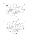
図7は、誘導機構に関する別実施形態を説明する図であって、用紙巻取部(格納部)と誘導機構とを示す概略構成図である。図7に示す別実施形態では、前述した実施形態に係るプリンタ1のプリント部30において、イエローに対応するヘッド部73よりも搬送方向下流側に位置している部分が、上述の実施形態とは異なっている。即ち、この別実施形態では、ヘッド部73の下流側において、搬送機構38の一部として設けられて最下流側に配置された送り込み装置101と、格納部を構成する用紙巻取部102と、誘導機構とが備えられている。なお、別実施形態におけるその他の部分(制御装置20等のプリント部30以外の部分も含めたその他の部分)については、前述した実施形態に係るプリンタ1と同様に構成されている。
(Another embodiment)
FIG. 7 is a diagram illustrating another embodiment related to the guide mechanism, and is a schematic configuration diagram illustrating a paper winding unit (storage unit) and a guide mechanism. In another embodiment shown in FIG. 7, in the printing unit 30 of the printer 1 according to the above-described embodiment, a portion located on the downstream side in the transport direction from the head unit 73 corresponding to yellow is different from the above-described embodiment. Is different. That is, in this other embodiment, on the downstream side of the head unit 73, a feeding device 101 provided as a part of the transport mechanism 38 and disposed on the most downstream side, a paper winding unit 102 constituting the storage unit, And a guidance mechanism. In addition, other parts in other embodiments (other parts including parts other than the printing unit 30 such as the control device 20) are configured in the same manner as the printer 1 according to the above-described embodiment.

送り込み装置101は、ヘッド部73(印字部70)と用紙巻取部102との間において、用紙の搬送方向への搬送力を用紙に対して付与するとともに搬送経路を湾曲させるものとして構成されている。即ち、送り込み装置101は、上流側に配置された上流側ローラ101aと、下流側に配置された下流側ローラ10cと、両ローラ(101a、101b)に対向してその両ローラとの間で用紙を挟持して搬送する中心ローラ101bとを備えている。これらのローラ101a〜101cは駆動ローラと従動ローラとからなり、例えば、中心ローラ101bが駆動ローラを構成し、上流側ローラ101a及び下流側ローラ101cが従動ローラを構成している。送り込み装置101の駆動機構については、前述した実施形態における送り込みローラ対35と同様に構成されている。   The feeding device 101 is configured to apply a transport force in the transport direction of the sheet to the sheet and bend the transport path between the head unit 73 (print unit 70) and the sheet take-up unit 102. Yes. That is, the feeding device 101 includes a sheet between the upstream roller 101a disposed on the upstream side, the downstream roller 10c disposed on the downstream side, and both the rollers (101a and 101b). And a central roller 101b that conveys the paper while sandwiching it. These rollers 101a to 101c are composed of a driving roller and a driven roller. For example, the center roller 101b constitutes a driving roller, and the upstream roller 101a and the downstream roller 101c constitute a driven roller. The driving mechanism of the feeding device 101 is configured similarly to the feeding roller pair 35 in the above-described embodiment.

用紙巻取部102は、連動してそれぞれ周回動作を行う複数のベルトローラ104の集合体として構成されている。この用紙巻取部102には、一部が挿入口103として開口しており、搬送方向に搬送されてきた用紙は、この挿入口103を通じて用紙巻取部102内へと格納されるようになっている。そして、挿入口103から挿入されてきた用紙が、用紙供給部40で外側面であった面が外側面となるように巻回された状態で格納されるように、複数のベルトローラ104が、順番に連結されて配置されている。また、各ベルトローラ104は、一対のプーリとこれに周回するように掛け渡されるベルトとをそれぞれ備えており、隣り合うベルトローラ104間において連結されたプーリ間で回転駆動力が伝達されることで、各ベルトローラ104の各ベルトが連動して同一方向に周回するようになっている。なお、送り込み装置101の下流側ローラ101cと用紙巻取部102の端部に位置するベルトローラ104aとの間においては、それぞれのプーリに対して掛け渡されるベルト105が設けられており、これによって、複数のベルトローラ104が、送り込み装置101と連動して駆動されるようになっている。   The paper take-up unit 102 is configured as an aggregate of a plurality of belt rollers 104 that rotate in conjunction with each other. A part of the paper take-up unit 102 is opened as an insertion port 103, and the paper conveyed in the conveyance direction is stored in the paper take-up unit 102 through the insertion port 103. ing. The plurality of belt rollers 104 are stored so that the paper inserted from the insertion port 103 is stored in a state where the paper supply unit 40 is wound so that the outer surface is the outer surface. They are connected in order. Each belt roller 104 includes a pair of pulleys and a belt that wraps around the pulleys, and rotational driving force is transmitted between pulleys connected between adjacent belt rollers 104. Thus, the belts of the belt rollers 104 rotate in the same direction in conjunction with each other. In addition, between the downstream roller 101c of the feeding device 101 and the belt roller 104a located at the end of the paper take-up unit 102, a belt 105 is provided that spans the pulleys. A plurality of belt rollers 104 are driven in conjunction with the feeding device 101.

誘導機構は、第1規制部材106によって構成されている。この第1規制部材106は、挿入口103となる部分(記録媒体受け入れ開口部分)において、搬送方向に搬送されてくる用紙の表裏面にそれぞれ対向するように配置され、この用紙の搬送方向を規制可能な部材として形成されている。即ち、図7に示すように、第1規制部材106は、平行に配置される一対の平板状部材(106a、106b)として形成されている。このように、第1規制部材106を設けることで、搬送方向に搬送されてくる用紙を挿入口103のところにおいて用紙巻取部102内へと適正に誘導することができる。そのため、用紙の詰まりや搬送経路からの脱落等の搬送トラブルの発生を抑制することができる。また、この一対の平板状の部材(106a、106b)は、搬送されてくる用紙の先端を受け入れる側の端部107が、この一対の平板状部材(106a、106b)間の距離が広がるように開口して形成されている。これにより、搬送方向に搬送されてくる用紙を、一対の平板状部材(106a、106b)間に容易に挿入することができ、より確実に用紙を用紙巻取部102内へと誘導することができる。   The guide mechanism is configured by the first restricting member 106. The first restricting member 106 is disposed so as to face the front and back surfaces of the sheet conveyed in the conveying direction at the portion (recording medium receiving opening) which becomes the insertion port 103, and regulates the conveying direction of the sheet. It is formed as a possible member. That is, as shown in FIG. 7, the first regulating member 106 is formed as a pair of flat plate members (106a, 106b) arranged in parallel. As described above, by providing the first restricting member 106, it is possible to appropriately guide the sheet conveyed in the conveying direction into the sheet winding unit 102 at the insertion port 103. Therefore, it is possible to suppress the occurrence of conveyance troubles such as paper jams and dropping off from the conveyance path. Further, the pair of flat members (106a, 106b) are arranged such that the end portion 107 on the side for receiving the leading edge of the conveyed paper increases the distance between the pair of flat members (106a, 106b). An opening is formed. Thus, the sheet conveyed in the conveying direction can be easily inserted between the pair of flat plate members (106a, 106b), and the sheet can be more reliably guided into the sheet winding unit 102. it can.

また、誘導機構は、第1規制部材106に加えて、更に、第2規制部材108も備えている。この第2規制部材108は、送り込み装置101によって湾曲させられる用紙の搬送経路に沿ってその用紙の搬送方向を規制可能な部材として形成されている。即ち、図7に示すように、第2規制部材108は、上流側ローラ101aと下流側ローラ101bとの間に配置されるとともに、中心ローラ101bの周囲の一部に隙間を隔てて対向する位置に設けられている。そして、この第2規制部材108は中心ローラ101bの周囲表面に沿う湾曲面を有しており、搬送される用紙が通過するための隙間が、この湾曲面と中心ローラ101bの周囲表面との間に形成されている。このように、誘導機構として第2規制部材108も設けることで、搬送機構38が印字部70と用紙巻取部102との間において用紙の搬送経路を湾曲させつつ搬送する場合であっても、その湾曲経路に沿って用紙を搬送させて用紙巻取部102へと誘導することができる。   In addition to the first restricting member 106, the guide mechanism further includes a second restricting member 108. The second regulating member 108 is formed as a member capable of regulating the sheet conveyance direction along the sheet conveyance path bent by the feeding device 101. That is, as shown in FIG. 7, the second restricting member 108 is disposed between the upstream roller 101a and the downstream roller 101b and faces a part of the periphery of the center roller 101b with a gap therebetween. Is provided. The second restricting member 108 has a curved surface along the peripheral surface of the central roller 101b, and a gap for passing the conveyed paper is between the curved surface and the peripheral surface of the central roller 101b. Is formed. As described above, by providing the second restricting member 108 as a guiding mechanism, even when the transport mechanism 38 transports while curving the paper transport path between the printing unit 70 and the paper winding unit 102, The sheet can be conveyed along the curved path and guided to the sheet winding unit 102.

なお、第1規制部材については、記録媒体受け入れ部を備える格納部に対してであれば、広く適用可能なものであり、また、必ずしも上述した別実施形態のとおりでなくてもよく、特許請求の範囲に記載した限りにおいて様々な設計変更が可能なものである。また、送り込み装置及び第2規制部材の形態についても、様々な設計変更が可能なものである。   The first restricting member can be widely applied to the storage unit including the recording medium receiving unit, and does not necessarily have to be the same as the above-described another embodiment. As long as it is described in the range, various design changes are possible. Moreover, various design changes are possible also about the form of a feeding apparatus and a 2nd control member.

本発明の実施の形態に係るプリンタの外観斜視図である。1 is an external perspective view of a printer according to an embodiment of the present invention. 図1のプリンタの画像形成部の概略構成を示す図である。FIG. 2 is a diagram illustrating a schematic configuration of an image forming unit of the printer of FIG. 1. 図1のプリンタの搬送ローラ対と送り込みローラ対との動きを表す図である。It is a figure showing a motion of the conveyance roller pair of the printer of FIG. 1, and a sending roller pair. 図1のプリンタの主要部及びこれらが接続された制御装置についてのブロック図である。It is a block diagram about the principal part of the printer of FIG. 1, and the control apparatus to which these were connected. 1オーダーに含まれる複数のカラー画像が用紙の先端部近傍に印字されるときの様子を示す図である。It is a figure which shows a mode when the several color image contained in 1 order is printed in the front-end | tip part vicinity of a paper. プリンタ1での動作手順を示すフローチャートである。3 is a flowchart showing an operation procedure in the printer 1. 誘導機構に関する別実施形態を説明する図であって、用紙巻取部と誘導機構とを示す概略構成図である。It is a figure explaining another embodiment regarding a guide mechanism, Comprising: It is a schematic block diagram which shows a paper winding part and a guide mechanism.

符号の説明Explanation of symbols

1 サーマルプリンタ(プリンタ)
10 操作部
20 制御装置
21 最大巻取量記憶部
22 プリント情報記憶部
23 必要巻取量算出部
24 比較部
25 巻取量決定部
26 搬送量検知部
27a 搬送制御部(搬送制御手段)
27b 印字制御部(画像記録制御手段)
27c 切断制御部
30 プリント部
34 搬送ローラ対
36 エンコーダ
38 搬送機構
40 用紙供給部(供給部)
50 切断部
60 オーバーコート部
70 印字部(画像記録部)
71a〜73a サーマルヘッド(画像記録ヘッド)
80 用紙巻取部(格納部)
81 格納ケース
82 挿入口(記録媒体受け入れ開口部分)
82a 一方の端部(誘導機構)
83a〜83d 巻き取りローラ
91 用紙検出センサ
96 プリントボックス
1 Thermal printer (printer)
DESCRIPTION OF SYMBOLS 10 Operation part 20 Control apparatus 21 Maximum winding amount memory | storage part 22 Print information storage part 23 Required winding amount calculation part 24 Comparison part 25 Winding amount determination part 26 Conveyance amount detection part 27a Conveyance control part (conveyance control means)
27b Print control unit (image recording control means)
27c Cutting Control Unit 30 Printing Unit 34 Conveying Roller Pair 36 Encoder 38 Conveying Mechanism 40 Paper Supply Unit (Supply Unit)
50 Cutting unit 60 Overcoat unit 70 Printing unit (image recording unit)
71a to 73a Thermal head (image recording head)
80 Paper take-up part (storage part)
81 Storage case 82 Insertion opening (recording medium receiving opening)
82a One end (guidance mechanism)
83a to 83d Winding roller 91 Paper detection sensor 96 Print box

Claims (9)

記録媒体にカラー画像を記録可能な画像記録部と、
長尺の記録媒体を貯留した供給部と、
記録媒体を前記画像記録部に対向させつつ前記供給部から前記画像記録部に向かう第1の方向と、前記第1の方向と反対方向である第2の方向とに搬送可能な搬送機構と、
記録媒体の先端が前記画像記録部から前記第1の方向に離れた位置に達するまで記録媒体が前記第1の方向に搬送された後に前記第2の方向に搬送されるように、前記搬送機構を制御する搬送制御手段と、
記録媒体において前記画像記録部に対して前記供給部とは反対側にある領域の少なくとも一部を格納可能な格納部と、
記録媒体が前記格納部内に格納されるように、前記第1の方向に搬送される記録媒体を当該格納部の記録媒体受け入れ開口部分において誘導する誘導機構と、
前記搬送機構によって前記第2の方向に搬送されている記録媒体に前記画像記録部によって複数のカラー画像が記録されるように、前記画像記録部を制御する画像記録制御手段と、
を備えていることを特徴とするプリンタ。
An image recording unit capable of recording a color image on a recording medium;
A supply unit storing a long recording medium;
A transport mechanism capable of transporting a recording medium in a first direction from the supply unit to the image recording unit and a second direction opposite to the first direction while facing the image recording unit;
The transport mechanism so that the recording medium is transported in the second direction after being transported in the first direction until the leading end of the recording medium reaches a position away from the image recording unit in the first direction. Transport control means for controlling
A storage unit capable of storing at least a part of an area on the opposite side of the supply unit with respect to the image recording unit in the recording medium;
A guide mechanism for guiding the recording medium conveyed in the first direction at the recording medium receiving opening of the storage unit so that the recording medium is stored in the storage unit;
Image recording control means for controlling the image recording unit so that a plurality of color images are recorded by the image recording unit on a recording medium being conveyed in the second direction by the conveyance mechanism;
A printer characterized by comprising:
前記搬送機構は、前記供給部と前記画像記録部との間において記録媒体に搬送力を付与することによって、記録媒体を前記第2の方向に搬送可能であることを特徴とする請求項1に記載のプリンタ。   2. The conveyance mechanism according to claim 1, wherein the conveyance mechanism can convey the recording medium in the second direction by applying a conveyance force to the recording medium between the supply unit and the image recording unit. The printer described. 前記供給部は、巻回された状態の長尺の記録媒体を貯留し、
前記格納部は、前記供給部で外側面であった面が外側面となるように巻回された状態で記録媒体を格納することを特徴とする請求項1又は請求項2に記載のプリンタ。
The supply unit stores a long recording medium in a wound state,
3. The printer according to claim 1, wherein the storage unit stores the recording medium in a state in which the storage unit is wound so that a surface which is an outer surface of the supply unit becomes an outer surface.
前記格納部は、回転自在に支持された回転体であって前記第1の方向に搬送される記録媒体が当該格納部内において巻回されつつ格納されるように誘導される誘導経路に沿って複数配置されている回転体を更に備えていることを特徴とする請求項3に記載のプリンタ。   The storage unit is a rotating body that is rotatably supported, and a plurality of storage units are guided along a guide path that guides the recording medium conveyed in the first direction to be stored while being wound in the storage unit. The printer according to claim 3, further comprising a rotating body arranged. 前記回転体は、前記誘導経路を横断する方向で当該誘導経路に平行な軸の回りに回転自在に支持されたローラであることを特徴とする請求項4に記載のプリンタ。   The printer according to claim 4, wherein the rotating body is a roller that is rotatably supported around an axis parallel to the guide path in a direction crossing the guide path. 前記誘導機構は、前記記録媒体受け入れ開口部分において、記録媒体の表裏面にそれぞれ対向して当該記録媒体の搬送方向を規制可能な第1規制部材であることを特徴とする請求項1乃至請求項5のいずれか1項に記載のプリンタ。   2. The guide mechanism according to claim 1, wherein the guide mechanism is a first restricting member capable of restricting a conveyance direction of the recording medium facing the front and back surfaces of the recording medium at the recording medium receiving opening. 6. The printer according to any one of 5 above. 前記第1規制部材は、平行に配置される一対の平板状部材として形成されていることを特徴とする請求項6に記載のプリンタ。   The printer according to claim 6, wherein the first restricting member is formed as a pair of flat plate-like members arranged in parallel. 前記一対の平板状部材は、記録媒体の先端を受け入れる側の端部が、当該一対の平板状部材間の距離が広がるように形成されていることを特徴とする請求項8に記載のプリンタ。   9. The printer according to claim 8, wherein the pair of flat plate-like members are formed so that end portions on the side of receiving the leading end of the recording medium have a wider distance between the pair of flat plate members. 前記搬送機構は、前記画像記録部と前記格納部との間において、前記第1の方向への搬送力を記録媒体に付与するとともに搬送経路を湾曲させる送り込み装置を更に備え、
前記誘導機構は、前記送り込み装置によって湾曲させられる前記搬送経路に沿って記録媒体の搬送方向を規制可能な第2規制部材を更に備えていることを特徴とする請求項1乃至請求項8のいずれか1項に記載のプリンタ。
The transport mechanism further includes a feeding device that imparts a transport force in the first direction to the recording medium between the image recording unit and the storage unit and curves the transport path;
9. The guide mechanism according to claim 1, further comprising a second regulating member capable of regulating a conveyance direction of the recording medium along the conveyance path that is bent by the feeding device. The printer according to claim 1.
JP2004118864A 2004-04-14 2004-04-14 Printer Pending JP2005297428A (en)

Priority Applications (1)

Application Number Priority Date Filing Date Title
JP2004118864A JP2005297428A (en) 2004-04-14 2004-04-14 Printer

Applications Claiming Priority (1)

Application Number Priority Date Filing Date Title
JP2004118864A JP2005297428A (en) 2004-04-14 2004-04-14 Printer

Publications (1)

Publication Number Publication Date
JP2005297428A true JP2005297428A (en) 2005-10-27

Family

ID=35329555

Family Applications (1)

Application Number Title Priority Date Filing Date
JP2004118864A Pending JP2005297428A (en) 2004-04-14 2004-04-14 Printer

Country Status (1)

Country Link
JP (1) JP2005297428A (en)

Similar Documents

Publication Publication Date Title
CN100400296C (en) printer
CN100357111C (en) Thermal printer
JP4424156B2 (en) Printer
JP4496814B2 (en) Printer and printing method
JP2006103102A (en) Printer
JP4385813B2 (en) Printer
JP4363284B2 (en) Printer
JP4367301B2 (en) Printer and recording medium conveying apparatus
JP4492201B2 (en) Printer
JP4400383B2 (en) Printer
JP4424050B2 (en) Printer
JP4424052B2 (en) Printer
JP2005297428A (en) Printer
JP4395744B2 (en) Printer
JP4501608B2 (en) Printer
JP2005297315A (en) Printer
JP2005271503A (en) Printer
JP2005271452A (en) Printer
JP4492163B2 (en) Printer
JP2005280061A (en) Printer
JP2005288991A (en) Printer
JP2005313509A (en) Printer
JP2007055047A (en) Printer
JP2006110925A (en) Printer and printing method
JP2005288970A (en) Printer

Legal Events

Date Code Title Description
A621 Written request for application examination

Free format text: JAPANESE INTERMEDIATE CODE: A621

Effective date: 20070315

A977 Report on retrieval

Free format text: JAPANESE INTERMEDIATE CODE: A971007

Effective date: 20090219

A131 Notification of reasons for refusal

Free format text: JAPANESE INTERMEDIATE CODE: A131

Effective date: 20090224

A521 Written amendment

Free format text: JAPANESE INTERMEDIATE CODE: A523

Effective date: 20090414

A02 Decision of refusal

Free format text: JAPANESE INTERMEDIATE CODE: A02

Effective date: 20091117