JP2016500410A - Lock mechanism - Google Patents
Lock mechanism Download PDFInfo
- Publication number
- JP2016500410A JP2016500410A JP2015547886A JP2015547886A JP2016500410A JP 2016500410 A JP2016500410 A JP 2016500410A JP 2015547886 A JP2015547886 A JP 2015547886A JP 2015547886 A JP2015547886 A JP 2015547886A JP 2016500410 A JP2016500410 A JP 2016500410A
- Authority
- JP
- Japan
- Prior art keywords
- locking
- locking element
- quick coupler
- teeth
- engaging means
- Prior art date
- Legal status (The legal status is an assumption and is not a legal conclusion. Google has not performed a legal analysis and makes no representation as to the accuracy of the status listed.)
- Pending
Links
- 230000007246 mechanism Effects 0.000 title claims abstract description 64
- 230000009471 action Effects 0.000 claims abstract description 11
- 230000008859 change Effects 0.000 claims description 2
- 230000000694 effects Effects 0.000 description 2
- 238000000034 method Methods 0.000 description 2
- 230000000717 retained effect Effects 0.000 description 2
- 208000027418 Wounds and injury Diseases 0.000 description 1
- 230000002457 bidirectional effect Effects 0.000 description 1
- 230000006835 compression Effects 0.000 description 1
- 238000007906 compression Methods 0.000 description 1
- 230000006378 damage Effects 0.000 description 1
- 208000014674 injury Diseases 0.000 description 1
- 230000003993 interaction Effects 0.000 description 1
- 238000004519 manufacturing process Methods 0.000 description 1
- 230000004048 modification Effects 0.000 description 1
- 238000012986 modification Methods 0.000 description 1
- 230000008569 process Effects 0.000 description 1
Images
Classifications
-
- E—FIXED CONSTRUCTIONS
- E02—HYDRAULIC ENGINEERING; FOUNDATIONS; SOIL SHIFTING
- E02F—DREDGING; SOIL-SHIFTING
- E02F3/00—Dredgers; Soil-shifting machines
- E02F3/04—Dredgers; Soil-shifting machines mechanically-driven
- E02F3/28—Dredgers; Soil-shifting machines mechanically-driven with digging tools mounted on a dipper- or bucket-arm, i.e. there is either one arm or a pair of arms, e.g. dippers, buckets
- E02F3/36—Component parts
- E02F3/3604—Devices to connect tools to arms, booms or the like
- E02F3/3609—Devices to connect tools to arms, booms or the like of the quick acting type, e.g. controlled from the operator seat
- E02F3/3622—Devices to connect tools to arms, booms or the like of the quick acting type, e.g. controlled from the operator seat with a hook and a locking element acting on a pin
-
- E—FIXED CONSTRUCTIONS
- E02—HYDRAULIC ENGINEERING; FOUNDATIONS; SOIL SHIFTING
- E02F—DREDGING; SOIL-SHIFTING
- E02F3/00—Dredgers; Soil-shifting machines
- E02F3/04—Dredgers; Soil-shifting machines mechanically-driven
- E02F3/28—Dredgers; Soil-shifting machines mechanically-driven with digging tools mounted on a dipper- or bucket-arm, i.e. there is either one arm or a pair of arms, e.g. dippers, buckets
- E02F3/36—Component parts
- E02F3/3604—Devices to connect tools to arms, booms or the like
- E02F3/3609—Devices to connect tools to arms, booms or the like of the quick acting type, e.g. controlled from the operator seat
- E02F3/3627—Devices to connect tools to arms, booms or the like of the quick acting type, e.g. controlled from the operator seat with a hook and a longitudinal locking element
-
- E—FIXED CONSTRUCTIONS
- E02—HYDRAULIC ENGINEERING; FOUNDATIONS; SOIL SHIFTING
- E02F—DREDGING; SOIL-SHIFTING
- E02F3/00—Dredgers; Soil-shifting machines
- E02F3/04—Dredgers; Soil-shifting machines mechanically-driven
- E02F3/28—Dredgers; Soil-shifting machines mechanically-driven with digging tools mounted on a dipper- or bucket-arm, i.e. there is either one arm or a pair of arms, e.g. dippers, buckets
- E02F3/36—Component parts
- E02F3/3604—Devices to connect tools to arms, booms or the like
- E02F3/3609—Devices to connect tools to arms, booms or the like of the quick acting type, e.g. controlled from the operator seat
- E02F3/364—Devices to connect tools to arms, booms or the like of the quick acting type, e.g. controlled from the operator seat using wedges
-
- E—FIXED CONSTRUCTIONS
- E02—HYDRAULIC ENGINEERING; FOUNDATIONS; SOIL SHIFTING
- E02F—DREDGING; SOIL-SHIFTING
- E02F3/00—Dredgers; Soil-shifting machines
- E02F3/04—Dredgers; Soil-shifting machines mechanically-driven
- E02F3/28—Dredgers; Soil-shifting machines mechanically-driven with digging tools mounted on a dipper- or bucket-arm, i.e. there is either one arm or a pair of arms, e.g. dippers, buckets
- E02F3/36—Component parts
- E02F3/3604—Devices to connect tools to arms, booms or the like
- E02F3/3609—Devices to connect tools to arms, booms or the like of the quick acting type, e.g. controlled from the operator seat
- E02F3/365—Devices to connect tools to arms, booms or the like of the quick acting type, e.g. controlled from the operator seat with redundant latching means, e.g. for safety purposes
-
- E—FIXED CONSTRUCTIONS
- E02—HYDRAULIC ENGINEERING; FOUNDATIONS; SOIL SHIFTING
- E02F—DREDGING; SOIL-SHIFTING
- E02F3/00—Dredgers; Soil-shifting machines
- E02F3/04—Dredgers; Soil-shifting machines mechanically-driven
- E02F3/28—Dredgers; Soil-shifting machines mechanically-driven with digging tools mounted on a dipper- or bucket-arm, i.e. there is either one arm or a pair of arms, e.g. dippers, buckets
- E02F3/36—Component parts
- E02F3/3604—Devices to connect tools to arms, booms or the like
- E02F3/3609—Devices to connect tools to arms, booms or the like of the quick acting type, e.g. controlled from the operator seat
- E02F3/3663—Devices to connect tools to arms, booms or the like of the quick acting type, e.g. controlled from the operator seat hydraulically-operated
-
- Y—GENERAL TAGGING OF NEW TECHNOLOGICAL DEVELOPMENTS; GENERAL TAGGING OF CROSS-SECTIONAL TECHNOLOGIES SPANNING OVER SEVERAL SECTIONS OF THE IPC; TECHNICAL SUBJECTS COVERED BY FORMER USPC CROSS-REFERENCE ART COLLECTIONS [XRACs] AND DIGESTS
- Y10—TECHNICAL SUBJECTS COVERED BY FORMER USPC
- Y10T—TECHNICAL SUBJECTS COVERED BY FORMER US CLASSIFICATION
- Y10T403/00—Joints and connections
- Y10T403/59—Manually releaseable latch type
- Y10T403/591—Manually releaseable latch type having operating mechanism
Landscapes
- Engineering & Computer Science (AREA)
- Mechanical Engineering (AREA)
- Mining & Mineral Resources (AREA)
- Civil Engineering (AREA)
- General Engineering & Computer Science (AREA)
- Structural Engineering (AREA)
- Quick-Acting Or Multi-Walled Pipe Joints (AREA)
- Shovels (AREA)
Abstract
クイックカプラA用のロック機構10は、可動ロック要素11を有する。偏倚要素13は、ロック要素11を偏倚させて第1の方向に移動させるように適合される。作用部材12は、ロック要素11を偏倚要素13の偏倚に反して移動させるように構成される。ロック要素11は、歯または鋸歯19を有し、歯または鋸歯19は、ロック要素11が偏倚要素13によって第1の方向に移動されるとき、クイックカプラAの可動楔形要素Fに結合されたさらなる歯または鋸歯20と係合可能であり、楔形要素11を移動しないようにロックする。ロック要素11の移動は、圧縮力を生み出し、この圧縮力により、歯/鋸歯19、20は押込式に噛合して噛合状態を保つ。The locking mechanism 10 for the quick coupler A has a movable locking element 11. The biasing element 13 is adapted to bias the locking element 11 and move it in the first direction. The action member 12 is configured to move the lock element 11 against the bias of the biasing element 13. The locking element 11 has teeth or serrations 19, which are further coupled to the movable wedge-shaped element F of the quick coupler A when the locking element 11 is moved in the first direction by the biasing element 13. Engageable with teeth or saw teeth 20 and locks wedge-shaped element 11 against movement. The movement of the locking element 11 creates a compressive force that causes the teeth / saw teeth 19, 20 to engage in a push-in manner and remain engaged.
Description
本発明は、クイックカプラ用のロック機構に関する。 The present invention relates to a locking mechanism for a quick coupler.
掘削機などの土木機械に付属品、例えばバケツを取り付けるためのクイックカプラが知られている。また、クイックカプラを油圧作動させることも知られている。油圧作動式のクイックカプラに関して生じ得る危険は、油圧系統故障時に、クイックカプラが、付属品を作業位置で保定できなくなる可能性があることである。例えば、カプラは、取付点の1つで付属品を保持できなくなることがあり、その結果、付属品はカプラから振り下ろされることがある。この結果、カプラが故障したときに付属品の近くにいる人の死傷を引き起こすおそれがある。 Quick couplers for attaching accessories such as buckets to civil engineering machines such as excavators are known. It is also known to hydraulically operate a quick coupler. A possible danger with hydraulically actuated quick couplers is that in the event of a hydraulic system failure, the quick coupler may not be able to hold the accessories in the working position. For example, the coupler may not be able to hold the accessory at one of the attachment points, so that the accessory may be swung down from the coupler. As a result, there is a risk of causing death or injury to a person near the accessory when the coupler fails.
したがって、本発明の目的は、クイックカプラ用のロック機構であって、クイックカプラによって取り付けられた付属品が、油圧系統故障時に作業位置でカプラに保持されるロック機構を提供する、または少なくとも公衆に有用な選択肢を提供することである。 Accordingly, it is an object of the present invention to provide a locking mechanism for a quick coupler, wherein an accessory attached by the quick coupler is provided to the coupler in the working position in the event of a hydraulic system failure, or at least to the public. It is to provide useful options.
広範には、本発明の一態様によれば、クイックカプラ用のロック機構であって、可動ロック要素と、第1の方向に移動するようにロック要素を偏倚させるように適合された偏倚手段と、偏倚手段の偏倚に反してロック要素を移動させるように構成された作用部材とを含み、ロック要素は、係合手段を有し、係合手段は、ロック要素が偏倚手段によって第1の方向に移動されるとき、クイックカプラの可動楔形要素に結合されたさらなる係合手段と係合可能であり、楔形要素を移動しないようにロックするロック機構が提供される。 Broadly, according to one aspect of the present invention, a locking mechanism for a quick coupler comprising a movable locking element and biasing means adapted to bias the locking element to move in a first direction. And an actuating member configured to move the locking element against the bias of the biasing means, the locking element having an engaging means, the engaging means having a first direction by the biasing means. A locking mechanism is provided that is engageable with further engagement means coupled to the movable wedge-shaped element of the quick coupler when locked to lock the wedge-shaped element against movement.
広範には、本発明の第2の態様では、可動楔形要素と、可動要素を移動させるための油圧作動可能な動作手段と、可動ロック要素と、ロック要素を偏倚させて第1の方向に移動させるように適合された偏倚手段と、第1の方向に移動しないようにロック要素を制止するように構成された作用部材とを含むクイックカプラであって、ロック要素は、係合手段を有し、係合手段は、動作手段への油圧供給の故障時にロック要素が偏倚手段によって第1の方向に移動できるようになったとき、可動要素と係合可能であり、可動要素を移動しないようにロックするクイックカプラが提供される。 Broadly, in the second aspect of the invention, the movable wedge-shaped element, the hydraulically actuable operating means for moving the movable element, the movable locking element, and the locking element biased to move in the first direction. A quick coupler including a biasing means adapted to cause and a working member configured to restrain the locking element from moving in a first direction, the locking element having engagement means The engaging means is engageable with the movable element and does not move the movable element when the locking element can be moved in the first direction by the biasing means when the hydraulic supply to the operating means fails. A quick coupler for locking is provided.
本発明の好ましい形態では、偏倚手段は、機械的な偏倚機構である。 In a preferred form of the invention, the biasing means is a mechanical biasing mechanism.
好ましくは、機械的な偏倚機構は、少なくとも1つのばねである。 Preferably, the mechanical biasing mechanism is at least one spring.
好ましい形態では、作用部材は、油圧作動式のリニアアクチュエータである。 In a preferred form, the working member is a hydraulically actuated linear actuator.
本発明の好ましい形態では、作用部材は、楔形要素用の動作手段の油圧源からの油圧によって動作される。 In a preferred form of the invention, the working member is operated by hydraulic pressure from the hydraulic source of the operating means for the wedge-shaped element.
好ましくは、本発明の一形態では、係合手段とさらなる係合手段はどちらも、相互噛合するように構成された複数の歯によって形成される。 Preferably, in one form of the invention, the engagement means and the further engagement means are both formed by a plurality of teeth configured to mesh with each other.
好ましくは、ロック要素の移動は、圧縮力を生み出し、この圧縮力により、歯は押込式に噛合して噛合状態を保つ。 Preferably, the movement of the locking element creates a compressive force that causes the teeth to mesh in a push-in manner and remain engaged.
本発明の好ましい一形態では、ストップが提供され、ストップは、ロック要素が作用部材によって制止されるときにロック要素と係合可能であり、それにより係合手段とさらなる係合手段との間に隙間を生成する。 In a preferred form of the invention, a stop is provided, the stop being engageable with the locking element when the locking element is restrained by the action member, so that between the engaging means and the further engaging means. Create a gap.
一形態では、さらなる係合手段は、可動要素に結合するように適合された把持構成要素の一部である。 In one form, the further engagement means is part of a gripping component adapted to couple to the movable element.
一形態では、ロック要素は、駆動構成要素に可動に結合される。 In one form, the locking element is movably coupled to the drive component.
一形態では、ロック要素および駆動構成要素は、偏倚手段によるロック要素の移動をロック要素の側方向移動に変えるように適合された相互係合駆動面を有する。好ましくは、この形態では、ロック要素および駆動構成要素は、摺動可能に係合されたレールとガイドをさらに含む。 In one form, the locking element and the drive component have an interengaging drive surface adapted to change the movement of the locking element by the biasing means into a lateral movement of the locking element. Preferably, in this configuration, the locking element and the drive component further include a slidably engaged rail and guide.
カプラの一形態では、複数のロック機構が存在する。 In one form of coupler, there are multiple locking mechanisms.
本発明の一実施形態およびクイックカプラへのその適用の以下のより詳細な説明において、本願の一部を成す図面を参照する。 In the following more detailed description of an embodiment of the invention and its application to a quick coupler, reference is made to the drawings that form a part of this application.
本発明によれば、本発明のロック機構は、クイックカプラへの油圧系統故障が発生するとすぐに楔体トングに係合して、移動しないようにロックする。それにより、楔体トングは、クイックカプラによって取り付けられた付属品の取付点が外れるおそれがあるような移動を防止される。 According to the present invention, the locking mechanism of the present invention engages the wedge body tongue as soon as a hydraulic system failure to the quick coupler occurs and locks it against movement. Thereby, the wedge body tongue is prevented from moving such that the attachment point of the accessory attached by the quick coupler may be removed.
まず図1を参照すると、本出願人が製造している既知の形態のクイックカプラAと、そのクイックカプラに組み込まれたときの本発明のロック機構10の第1の実施形態とが示されている。クイックカプラAは、それが取り付けられている機械の油圧機構によって油圧作動される。カプラの本体Bは取付点Cを有し、取付点Cで、カプラは例えば掘削機(図示せず)のアームに取り付けられる。
Referring first to FIG. 1, there is shown a known form of quick coupler A manufactured by the applicant and a first embodiment of the
本体Bはフック形部分Dを有し、フック形部分Dに付属品(図示せず)の取付ピンの1つが係合する。付属品の別の取付ピンは、凹部Eに位置する。油圧作動式の楔形要素またはトングF(本明細書では以後「楔体F」と呼ぶ)は、付属品取付ピンを凹部Eで捕捉するように延出可能であり、それにより付属品はその作業位置でカプラAに結合される。 The main body B has a hook-shaped portion D, and one of the attachment pins (not shown) of the accessory engages with the hook-shaped portion D. Another attachment pin of the accessory is located in the recess E. A hydraulically actuated wedge-shaped element or tongue F (hereinafter referred to as “wedge body F”) can be extended to catch the accessory mounting pin in the recess E, so that the accessory can perform its work. Coupled to coupler A in position.
したがって、カプラAへの油圧力が途絶えた場合、楔体Fは後退することがあり、これにより取付ピンは凹部Eから外れる。フック形部分Dにある他のピンが所定位置で保定されない場合、付属品は、掘削機アームから落下するおそれがある。しかし、(例えばニュージーランド特許第552294号/第546893号明細書に記載されて特許請求されている本出願人らのI Lock装置によって)フック形部分Dのピンが保定されている場合、付属品は、カプラAから完全には落ちずに、フック形部分Dのピンの位置で振り下ろされる。 Therefore, when the oil pressure to the coupler A is interrupted, the wedge body F may be retracted, whereby the mounting pin is detached from the recess E. If the other pins in the hook-shaped portion D are not held in place, the accessory may fall from the excavator arm. However, if the hook-shaped portion D pin is retained (eg, by Applicants' I Lock device as described and claimed in New Zealand Patent Nos. 552294/546893), the accessory is Without being completely dropped from the coupler A, it is swung down at the pin position of the hook-shaped portion D.
図1に示されるカプラAの形態では、楔体Fは、油圧シリンダGによって形成される動作手段の一部であり、油圧シリンダGは、楔体Fの延出および後退を制御する。これは、シリンダGと楔体Fの構成が取ることができる形態の一例にすぎない。 In the form of the coupler A shown in FIG. 1, the wedge body F is a part of the operating means formed by the hydraulic cylinder G, and the hydraulic cylinder G controls the extension and retraction of the wedge body F. This is merely an example of the form that the configurations of the cylinder G and the wedge body F can take.
図示されるカプラAの形態では、ロック機構10は、シリンダG/楔体Fのインターフェースに一体化されるが、これは、本発明のロック機構をクイックカプラ内に組み込むことができる形態の一例にすぎない。さらなる実施形態は、図6〜図22を参照して後述する。
In the illustrated coupler A configuration, the
次に図2(および図3におけるその関連の詳細図)を参照すると、ロック機構10は、ロック要素11(本明細書では以後「ラッチ11」と呼ぶ)と、好ましくはリニアアクチュエータ(例えば油圧シリンダ)の形態での作用部材12と、好ましくは例えばばねの形態での機械的な偏倚要素13とを含む。シリンダ12は、楔体Fが後退されるときに機械の油圧機構によって動作可能であるように構成される(図4参照)。機械的な偏倚機構は、ラッチ11を偏倚させて、符号Xによって示される第1の方向に移動させる。
Referring now to FIG. 2 (and its associated detail in FIG. 3), the
ラッチ11は、実質的に楔形状である。ラッチ11の表面と、カプラ本体Bに対して固定された表面とは、摺動インターフェース14を形成する。摺動インターフェース14については、本明細書で以下により詳細に述べる。ラッチ11は固定面16を有し、固定面16に対してシリンダが作用することができる。したがって、図1〜図5に示される第1の好ましい実施形態では、ショルダ15は固定面16を提供し、この固定面16にシリンダ12が係合可能である。
The
ばね偏倚要素13の一端は、ラッチ11のポケット(穴)17内に位置する。ばね13の他端は、固定面18に係合する。
One end of the
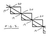
インターフェース14の一方の面を形成するラッチ11の表面は、歯または鋸歯19(本明細書では以後「歯19」と呼ぶ)を設けられ、歯19は、カプラの楔体Fに結合された歯または鋸歯20(本明細書では以後「歯20」と呼ぶ)に対向して位置され、相互係合可能である(詳細は図3参照)。歯20は、楔体Fまたは楔体を動作させるシリンダGのどこかに取付け可能な(第2の実施形態で述べる)要素の一部でよい。しかし、歯20と楔体Fの接続の実現は本発明にとっては重要でなく、重要な条件は、歯20が楔体Fと共に移動することである。
The surface of the
図3の部分詳細図は、歯組19と20の好ましい構成を示す。しかし、それらは、本明細書において以下で明らかになる機能パラメータを実現するという条件の下で様々な形態を取ることができる。 The partial detail view of FIG. 3 shows a preferred configuration of the tooth sets 19 and 20. However, they can take various forms, provided that they implement the functional parameters that will become apparent herein below.
歯組19と20は、楔体Fがその作用楔合位置に移動(延出)されたときに、接触角により歯20が歯19に乗り上げるようなものである。図3の詳細図は、歯20が歯19に乗り上げたときの歯組19と20を示す。楔体Fが延出されるとき、ラッチ11は、ばね13の張力に反して移動することができ、歯19と20は、楔体Fの延出をラッチ11が妨げないように互いに乗り上げる。
The tooth sets 19 and 20 are such that when the wedge body F is moved (extended) to its working wedge engagement position, the
楔体Fがその延出位置に移動されると、ばね13は、ラッチ11を方向Xに押して、歯19と20の係合を保証し、それにより楔体Fをその延出位置でロックする。
When the wedge body F is moved to its extended position, the
通常動作状況下では、楔体Fを後退させるためにカプラ用の制御機能を動作させる。その結果、両方向作用シリンダGの後退側に油圧が加えられ、それと同時に、シリンダGは作用部材12に圧力を加える。したがって、作用部材12は、解除アクチュエータ26を延出させ、ショルダ15の表面16に圧力を加え、この圧力により、ラッチ11は、偏倚ばね13の圧力に反して、すなわち符号Yによって示される方向に移動する。
Under normal operating conditions, the coupler control function is operated to retract the wedge body F. As a result, hydraulic pressure is applied to the backward side of the bidirectional working cylinder G, and at the same time, the cylinder G applies pressure to the working
図面の図1〜図5に示される好ましい構成では、ラッチ11はストップと接触しており、このストップは、簡便には表面18によって形成される。ラッチ11がストップ18に当たると、歯19と20の間に隙間(符号Zによって示される)が形成される。これは、楔体Fが何ら干渉を受けずに後退することができることを保証する(図3)。
In the preferred configuration shown in FIGS. 1-5 of the drawings, the
しかし、カプラへの油圧供給の故障が生じ(これにより楔体シリンダGへの圧力がなくなり)、両方向作用シリンダGによって楔体Fがその作用(延出)位置で保持されなくなった場合にはいつでも、偏倚ばね13は、摺動インターフェース14に沿って方向Xにロック部材を押し続け、矢印21の方向で生じる圧縮負荷により、歯19と20を噛み合ったままにし、それにより、楔体Fをその延出位置にロックし続ける。
However, whenever a failure occurs in the supply of hydraulic pressure to the coupler (which eliminates the pressure on the wedge cylinder G) and the wedge body F is no longer held in its working (extension) position by the bi-directional working cylinder G. The biasing
その結果、矢印22の方向への楔体Fの後退を妨げ、したがって、油圧系統故障にも関わらず、楔体Fが凹部E内に付属品のピンを保定することを保証する。
As a result, the wedge body F is prevented from retreating in the direction of the
したがって、ロック機構10は、楔体Fをその延出位置でロックし、このロック効果は、油圧供給故障の発生時にも失われない。
Therefore, the
負荷が作用部材12に伝達されるまでに通る歯の数と、摺動角により生成される圧縮負荷とにより、歯19と20は、比較的小さくすることができ、これは、機構でのバックラッシュが非常に小さく、実質的に無段式のロック位置を生成することを意味する。その結果、楔体Fは、楔体Fが取る延出位置に関係なくロックされる。また、歯20は、歯19の全てまたは実質的に全てに噛み合う。
Due to the number of teeth that pass until the load is transmitted to the working
図1に示されるタイプのカプラでは、カプラ楔体シリンダGと楔体インターフェースとの間にあるロック機構の位置により、市場での既存のカプラ製品のための後付けキットを作製することができる。これらのキットは、現場で取り付けることができる。したがって、当業者は、本明細書で図示して説明するタイプのカプラ専用ではない後付けキットを形成することができることを理解されよう。 In the type of coupler shown in FIG. 1, the position of the locking mechanism between the coupler wedge cylinder G and the wedge interface allows a retrofit kit for existing coupler products on the market to be made. These kits can be installed in the field. Accordingly, those skilled in the art will appreciate that retrofit kits may be formed that are not dedicated to couplers of the type shown and described herein.
図6〜図22は、本発明のロック機構の第2の実施形態を示す。第1の実施形態と第2の実施形態の1つの相違点は、第2の実施形態では、楔体Fの下にあるただ1つの機構ではなく、好ましくは(図示するように)2つのロック機構(シリンダGおよび楔体Fの各側に1つずつ)が存在することである。 6 to 22 show a second embodiment of the locking mechanism of the present invention. One difference between the first embodiment and the second embodiment is that in the second embodiment, there is preferably not two mechanisms under the wedge body F, but preferably two locks (as shown). The mechanism (one on each side of the cylinder G and the wedge body F) is present.
第1の実施形態の構成要素に対応する第2の実施形態の構成要素は、便宜上、同じ参照番号によって示される。 Components of the second embodiment that correspond to components of the first embodiment are indicated by the same reference numerals for convenience.
図6は、油圧シリンダGと楔体Fが見えるように本体Bの片側のプレート構成要素を取り外した状態でカプラAを示す。また、ロック機構10も示されているが、ロック機構10は、図7および後の図面でより良く見ることができる。
FIG. 6 shows the coupler A with the plate components on one side of the body B removed so that the hydraulic cylinder G and wedge body F can be seen. A
図7に示されるように、歯/鋸歯20(本明細書では以後、「歯20」)は、把持プレート構成要素(「把持部」)23の一部であり、把持部23は、適切な機械的固定具によって、楔体Fの二又区域の脚部28の凹んだ内面27に固定される。図示されるように、ロック機構10は、楔体Fの各脚部28に関連付けられている。
As shown in FIG. 7, the teeth / saw blades 20 (hereinafter “
同様に、駆動構成要素24およびラッチ11は、シリンダCの各側にある取付凹部29に関連付けられている。図示されるように、ラッチ11は、歯/鋸歯19(すなわち歯19)を有する。
Similarly, the
ここで、上述したように第2の実施形態では2つのロック機構10が存在するが、以下の説明では、便宜上、ロック機構10の一方のみの構成および動作を主に述べる。
Here, as described above, there are two
また、図7に示されるように、1対の作用部材12は、関連のアクチュエータ26とハウジング30の各側に取り付けられており、したがって、各作用部材12は、2つのロック機構10のそれぞれのラッチ11に対して作用することができる。
Also, as shown in FIG. 7, a pair of
図10〜図13は、シリンダGの実質的に下から4分の1の断面高さでの断面図である。図10は、ロック機構の構成要素11、23、および24を示し、歯19と20は完全に離れている(非掛止状態)。第1の実施形態で述べた隙間Zも示されている。ラッチ11の大きな鋸歯部分が、駆動構成要素24の対応する鋸歯部分と噛み合って、一連の駆動面31および32、ならびにストップ面33および34を形成し、エンドストップ面18(図11および図12参照)は、取付凹部29の端壁によって形成される。
10 to 13 are cross-sectional views of the cylinder G with a cross-sectional height substantially one-fourth from the bottom. FIG. 10 shows the
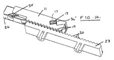
図14および図19〜図22から明らかなように、偏倚ばね13は、ラッチ11のポケット17内に位置され、これは、ストップ面34’に反して作用する。
As can be seen from FIGS. 14 and 19-22, the biasing
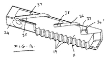
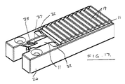
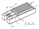
駆動構成要素24によるラッチ11の長手方向および側方向移動の制御は、駆動構成要素24が角度付きガイドレール35および36を有することによってさらに向上される。ガイドレール35および36は、ラッチ11のガイドスロット37および38と係合する(例えば図14〜図16参照)。これらのレール35および36は、ラッチプレートのスロット37および38と位置合わせされ、解除アクチュエータ26がラッチ11の裏面39を押すときに、解除プロセスを支援する。スロット面は、レール上で摺動し、それにより、ラッチ11を、駆動面31と32および偏倚ばね13による制御ラインに引き戻す。これらはまた、楔体Fが延出されるときに生じるラチェット効果も支援し、それにより、ラッチ11の移動が各歯組19と20の間で平行であり一定であることを保証する。
Control of the longitudinal and lateral movement of the
図17および図18は、ラッチ11が、図17の「後退」(非ラッチ)状態から図18の「延出」(係合)状態に移動することができる様子を示し、さらに、スロット37を有するラッチ11の部分、およびそれらのスロット37とレール35との相互作用を示す。
17 and 18 show how the
図19〜図22は、ポケット17内のばね13を示すある高さで取った断面を示す。これらの図面はまた、作用部材12のアクチュエータ26が、ラッチ11の表面39に係合し、ラッチ11を押して非掛止状態に戻すことができる様子も示す。好ましい形態では、解除アクチュエータ26は、それ自体の戻しばね40(図7参照)を有し、戻しばね40は、アクチュエータ26への油圧供給が切断されるときに、アクチュエータ26を後退させて、ラッチ11の接触面39(図19)から離す。これは、偏倚ばね13がラッチ11の移動のみを行えばよいことを保証する。
19 to 22 show a section taken at a height showing the
第2の実施形態は、第1の実施形態と同様に機能する。したがって、例えば、図10は、その完全に後退された(非ラッチ)位置に移動されたラッチ11を示し、ここで、隙間Zにより、楔体Fは、歯19と20の接触による干渉を受けずに移動することができる。
The second embodiment functions in the same manner as the first embodiment. Thus, for example, FIG. 10 shows the
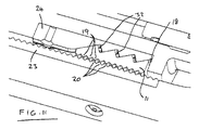
図11は、把持部23の後方向移動が歯19と20の相互係合をもたらす位置で歯19と20を示し、それにより、ロック機構10が係合され、したがって、把持部23が再び前進しない限り、ラッチ11も再び前進して非掛止状態になることができない。
FIG. 11 shows the
図12は、偏倚ばね13によって後方向に、かつ駆動構成要素24の角度面31によって外方向にラッチ11が移動し、それにより、2組の歯19と20が互いに接触する掛止状態に移動されている様子を示す。
FIG. 12 shows that the
図13は、ロック状態で完全に係合された歯19と20を示す。後方向への把持部23の移動は、ラッチ11を駆動構成要素24上でさらに引き戻し、それにより楔体Fを所定位置にロックする。
FIG. 13 shows the
ロック機構を形成する3つの主要な構成要素として、ラッチ11と、駆動構成要素20と、把持部23とがあり、さらに、ばね13が偏倚機構となっている。図面は、例示されるカプラ内部でのそれらの組立て構成を示すが、他のサイズのカプラでは変更することもできる。したがって、これらの部品は、使用可能な部品となるように設計されるが、組み立てられた状態でカプラの内部に組み込むこともできる。
As three main components forming the lock mechanism, there are a
本発明の技術的な側面は、駆動構成要素24に対するラッチ11の移動の角度と、歯組19と20の角度との関係である。好ましい形態では、ラッチ11は30度の角度で移動し、歯19、20は45度に設定される。動作中、歯19と20の前面が互いに接触するとき、それらは掛止状態になる。この後、係合状態(係合状態は、2組の歯19と20が永久的に噛み合う点である)にシフトするのに十分に把持部23が後方向に移動する場合、それらは、交差した角度関係により、歯19と20は引き離すことができなくなる。これは、ロック機構10を係合状態にし、把持部23が前進されて離れるまでは、引き離しは可能でない。この状態が図11に示されている。
A technical aspect of the present invention is the relationship between the angle of movement of the
本発明のロック機構は、油圧系統故障時に動作可能であり、クイックカプラによって取り付けられた付属品が作業位置でカプラに保定されることを保証する。 The locking mechanism of the present invention is operable in the event of a hydraulic system failure and ensures that the accessory attached by the quick coupler is retained on the coupler at the working position.
本発明を、特定の実施形態によって説明して図示してきた。本発明の範囲をそのような詳細に制約したり、何らかの形で制限したりすることは、本出願人の意図ではない。例えば、本明細書で示したカプラは、ロック機構を使用することができるカプラの1タイプにすぎない。本発明のロック機構は、図面に示し本明細書で述べたタイプ以外のカプラに取り付けられる後付けキットに提供することもできる。 The present invention has been described and illustrated by specific embodiments. It is not the Applicants' intention to limit the scope of the invention to such details or to limit it in any way. For example, the couplers shown herein are only one type of coupler that can use a locking mechanism. The locking mechanism of the present invention can also be provided in a retrofit kit that is attached to a coupler other than the type shown in the drawings and described herein.
本発明を異なる実施形態で実現することができる別の例では、解除アクチュエータは、油圧作動される必要がない。例えば、本発明が、ホースおよび油圧機構を有さないカプラに関連し、そのような構成では、本明細書で述べるタイプのカプラに加えて他の解除用手段を採用することもできることを当業者は容易に理解されよう。 In another example where the invention can be implemented in different embodiments, the release actuator need not be hydraulically actuated. For example, those skilled in the art will appreciate that the present invention relates to a coupler that does not have a hose and hydraulic mechanism, and in such a configuration, other release means may be employed in addition to the types of couplers described herein. Will be easily understood.
さらなる利点および修正は、当業者には容易に明らかであろう。したがって、本発明は、そのより広範な態様において、図示して説明した特定の詳細、代表的な製造手段および方法、ならびに例示的な実施例に限定されない。したがって、本出願人の全般的な発明の概念の精神および範囲から逸脱することなく、そのような詳細から離れることもできる。 Additional advantages and modifications will be readily apparent to those skilled in the art. Accordingly, the invention in its broader aspects is not limited to the specific details, representative manufacturing means and methods, and illustrative examples shown and described. Accordingly, departures may be made from such details without departing from the spirit or scope of applicants' general inventive concept.
Claims (22)
Applications Claiming Priority (3)
| Application Number | Priority Date | Filing Date | Title |
|---|---|---|---|
| NZ604110 | 2012-12-10 | ||
| NZ60411012 | 2012-12-10 | ||
| PCT/NZ2013/000219 WO2014092584A1 (en) | 2012-12-10 | 2013-12-04 | A locking mechanism |
Publications (2)
| Publication Number | Publication Date |
|---|---|
| JP2016500410A true JP2016500410A (en) | 2016-01-12 |
| JP2016500410A5 JP2016500410A5 (en) | 2017-01-12 |
Family
ID=50934716
Family Applications (1)
| Application Number | Title | Priority Date | Filing Date |
|---|---|---|---|
| JP2015547886A Pending JP2016500410A (en) | 2012-12-10 | 2013-12-04 | Lock mechanism |
Country Status (6)
| Country | Link |
|---|---|
| US (1) | US20150322646A1 (en) |
| EP (1) | EP2931981A4 (en) |
| JP (1) | JP2016500410A (en) |
| KR (1) | KR20150094691A (en) |
| AU (1) | AU2013360409A1 (en) |
| WO (1) | WO2014092584A1 (en) |
Families Citing this family (6)
| Publication number | Priority date | Publication date | Assignee | Title |
|---|---|---|---|---|
| CA3007341A1 (en) * | 2015-12-07 | 2017-06-15 | Wedgelock Equipment Limited | A locking device for a quick coupler |
| GB2576131B (en) | 2018-06-25 | 2023-01-18 | Miller Uk Ltd | Coupler |
| GB2610148B (en) * | 2018-06-25 | 2023-08-09 | Miller Uk Ltd | Coupler |
| CN113557336B (en) * | 2018-11-30 | 2023-10-24 | 休斯资产集团有限公司 | Coupling device |
| US11208785B2 (en) | 2018-12-12 | 2021-12-28 | Caterpillar Inc. | Tool coupling arrangement having zero offset |
| US10975544B1 (en) * | 2020-04-27 | 2021-04-13 | Caterpillar Inc. | Work tool coupling assembly with locking wedge |
Citations (5)
| Publication number | Priority date | Publication date | Assignee | Title |
|---|---|---|---|---|
| JPH0729044U (en) * | 1993-11-09 | 1995-06-02 | 敬植 山田 | Hydraulic excavator adapter |
| JP2001303609A (en) * | 2000-04-20 | 2001-10-31 | Yanmar Diesel Engine Co Ltd | Disengagement preventing structure for attachment of swiveling working vehicle |
| JP2002524673A (en) * | 1998-09-08 | 2002-08-06 | ミラー、ドーリーン、ジャックリーヌ | Quick coupler for bucket excavator |
| US20080296031A1 (en) * | 2007-05-30 | 2008-12-04 | Brandt Industries Ltd. | Quick Coupling Mechanism for Tool Attachment |
| US20120237283A1 (en) * | 2011-03-14 | 2012-09-20 | Brandt Industries Ltd. | Compact quick coupling mechanism for tool attachment |
Family Cites Families (9)
| Publication number | Priority date | Publication date | Assignee | Title |
|---|---|---|---|---|
| US5727342A (en) * | 1996-04-18 | 1998-03-17 | Wain-Roy, Inc. | Hydraulic latch pin assembly for coupling a tool to a construction equipment |
| DE59800510D1 (en) * | 1997-04-14 | 2001-04-12 | Baumaschinentechnik Gmbh Villa | QUICK-CHANGE DEVICE FOR EXCAVATORS |
| AU723305B1 (en) * | 1999-03-03 | 2000-08-24 | Barry Koster | Adaptor hitch with locking pin |
| US7306395B2 (en) * | 2001-11-29 | 2007-12-11 | Jrb Attachments, Llc | Spread-style coupler with supplemental lock system |
| EP2087178A2 (en) * | 2006-09-04 | 2009-08-12 | Miller UK Limited | Coupler |
| GB0720413D0 (en) * | 2007-10-18 | 2007-11-28 | Monaghan Conor | A Coupler |
| AT507598B1 (en) * | 2008-12-05 | 2012-03-15 | Wacker Neuson Linz Gmbh | DEVICE FOR REPLACEABLE TOOLS |
| EP2483480B1 (en) * | 2009-09-29 | 2020-11-18 | Doherty Engineered Attachments Limited | A coupler to engage a work attachment |
| KR101811461B1 (en) * | 2009-12-09 | 2017-12-21 | 에스 티 커플러스 리미티드 | Improvements relating to couplers |
-
2013
- 2013-12-04 US US14/650,858 patent/US20150322646A1/en not_active Abandoned
- 2013-12-04 WO PCT/NZ2013/000219 patent/WO2014092584A1/en active Application Filing
- 2013-12-04 EP EP13861826.9A patent/EP2931981A4/en not_active Withdrawn
- 2013-12-04 KR KR1020157018180A patent/KR20150094691A/en not_active Application Discontinuation
- 2013-12-04 AU AU2013360409A patent/AU2013360409A1/en not_active Abandoned
- 2013-12-04 JP JP2015547886A patent/JP2016500410A/en active Pending
Patent Citations (5)
| Publication number | Priority date | Publication date | Assignee | Title |
|---|---|---|---|---|
| JPH0729044U (en) * | 1993-11-09 | 1995-06-02 | 敬植 山田 | Hydraulic excavator adapter |
| JP2002524673A (en) * | 1998-09-08 | 2002-08-06 | ミラー、ドーリーン、ジャックリーヌ | Quick coupler for bucket excavator |
| JP2001303609A (en) * | 2000-04-20 | 2001-10-31 | Yanmar Diesel Engine Co Ltd | Disengagement preventing structure for attachment of swiveling working vehicle |
| US20080296031A1 (en) * | 2007-05-30 | 2008-12-04 | Brandt Industries Ltd. | Quick Coupling Mechanism for Tool Attachment |
| US20120237283A1 (en) * | 2011-03-14 | 2012-09-20 | Brandt Industries Ltd. | Compact quick coupling mechanism for tool attachment |
Also Published As
| Publication number | Publication date |
|---|---|
| AU2013360409A1 (en) | 2015-07-23 |
| WO2014092584A1 (en) | 2014-06-19 |
| EP2931981A1 (en) | 2015-10-21 |
| US20150322646A1 (en) | 2015-11-12 |
| KR20150094691A (en) | 2015-08-19 |
| EP2931981A4 (en) | 2016-11-02 |
Similar Documents
| Publication | Publication Date | Title |
|---|---|---|
| JP2016500410A (en) | Lock mechanism | |
| AU2017330165B2 (en) | Quick hitch coupler | |
| JP7189200B2 (en) | quick coupler | |
| AU2016365527B2 (en) | A locking device for a quick coupler | |
| US20160002877A1 (en) | Coupler for Coupling Attachments to Excavation Machines | |
| KR101422264B1 (en) | Safety device for quick coupler | |
| EP3052707B1 (en) | A coupler device | |
| KR101737019B1 (en) | Quick hitch coupler for backhoe bucket | |
| ITGE20090003A1 (en) | QUICK ATTACHMENT DEVICE, PARTICULARLY FOR OPERATING MACHINES | |
| WO2014165329A1 (en) | Locking system for quick coupler | |
| KR20210107779A (en) | Coupler for mating attachments to dipper arms | |
| CA3033338A1 (en) | Double safety device for quick coupler | |
| JP2016500410A5 (en) | ||
| KR101533841B1 (en) | Auto-safety device for quick coupler | |
| US20160251820A1 (en) | Work tool assembly and coupler | |
| WO2015099543A1 (en) | Improvements to couplers | |
| NZ618597B2 (en) | A locking mechanism | |
| IES20130069A2 (en) | A safety mechanism for a coupler for coupling an accessory to a dipper arm. | |
| KR20140094741A (en) | Bonnet locking device for heavy machinery cars | |
| RU2773496C2 (en) | Connector for attachment of detachable equipment to earthmoving machine (options) and earthmoving machine containing such a connector | |
| KR20150140603A (en) | quick coupler | |
| US218293A (en) | Improvement in reversible latches | |
| KR20210056069A (en) | Quick coupler for excavator | |
| NZ727394B2 (en) | A Locking Device for a Quick Coupler | |
| KR20140030640A (en) | Attachment mounting device of construction machine |
Legal Events
| Date | Code | Title | Description |
|---|---|---|---|
| A521 | Request for written amendment filed |
Free format text: JAPANESE INTERMEDIATE CODE: A523 Effective date: 20161122 |
|
| A621 | Written request for application examination |
Free format text: JAPANESE INTERMEDIATE CODE: A621 Effective date: 20161122 |
|
| A977 | Report on retrieval |
Free format text: JAPANESE INTERMEDIATE CODE: A971007 Effective date: 20170929 |
|
| A131 | Notification of reasons for refusal |
Free format text: JAPANESE INTERMEDIATE CODE: A131 Effective date: 20171010 |
|
| A02 | Decision of refusal |
Free format text: JAPANESE INTERMEDIATE CODE: A02 Effective date: 20180731 |


