KR20150094691A - A locking mechanism - Google Patents
A locking mechanism Download PDFInfo
- Publication number
- KR20150094691A KR20150094691A KR1020157018180A KR20157018180A KR20150094691A KR 20150094691 A KR20150094691 A KR 20150094691A KR 1020157018180 A KR1020157018180 A KR 1020157018180A KR 20157018180 A KR20157018180 A KR 20157018180A KR 20150094691 A KR20150094691 A KR 20150094691A
- Authority
- KR
- South Korea
- Prior art keywords
- locking
- quick coupler
- locking element
- wedge
- actuator
- Prior art date
Links
Images


Classifications
-
- E—FIXED CONSTRUCTIONS
- E02—HYDRAULIC ENGINEERING; FOUNDATIONS; SOIL SHIFTING
- E02F—DREDGING; SOIL-SHIFTING
- E02F3/00—Dredgers; Soil-shifting machines
- E02F3/04—Dredgers; Soil-shifting machines mechanically-driven
- E02F3/28—Dredgers; Soil-shifting machines mechanically-driven with digging tools mounted on a dipper- or bucket-arm, i.e. there is either one arm or a pair of arms, e.g. dippers, buckets
- E02F3/36—Component parts
- E02F3/3604—Devices to connect tools to arms, booms or the like
- E02F3/3609—Devices to connect tools to arms, booms or the like of the quick acting type, e.g. controlled from the operator seat
- E02F3/3622—Devices to connect tools to arms, booms or the like of the quick acting type, e.g. controlled from the operator seat with a hook and a locking element acting on a pin
-
- E—FIXED CONSTRUCTIONS
- E02—HYDRAULIC ENGINEERING; FOUNDATIONS; SOIL SHIFTING
- E02F—DREDGING; SOIL-SHIFTING
- E02F3/00—Dredgers; Soil-shifting machines
- E02F3/04—Dredgers; Soil-shifting machines mechanically-driven
- E02F3/28—Dredgers; Soil-shifting machines mechanically-driven with digging tools mounted on a dipper- or bucket-arm, i.e. there is either one arm or a pair of arms, e.g. dippers, buckets
- E02F3/36—Component parts
- E02F3/3604—Devices to connect tools to arms, booms or the like
- E02F3/3609—Devices to connect tools to arms, booms or the like of the quick acting type, e.g. controlled from the operator seat
- E02F3/3627—Devices to connect tools to arms, booms or the like of the quick acting type, e.g. controlled from the operator seat with a hook and a longitudinal locking element
-
- E—FIXED CONSTRUCTIONS
- E02—HYDRAULIC ENGINEERING; FOUNDATIONS; SOIL SHIFTING
- E02F—DREDGING; SOIL-SHIFTING
- E02F3/00—Dredgers; Soil-shifting machines
- E02F3/04—Dredgers; Soil-shifting machines mechanically-driven
- E02F3/28—Dredgers; Soil-shifting machines mechanically-driven with digging tools mounted on a dipper- or bucket-arm, i.e. there is either one arm or a pair of arms, e.g. dippers, buckets
- E02F3/36—Component parts
- E02F3/3604—Devices to connect tools to arms, booms or the like
- E02F3/3609—Devices to connect tools to arms, booms or the like of the quick acting type, e.g. controlled from the operator seat
- E02F3/364—Devices to connect tools to arms, booms or the like of the quick acting type, e.g. controlled from the operator seat using wedges
-
- E—FIXED CONSTRUCTIONS
- E02—HYDRAULIC ENGINEERING; FOUNDATIONS; SOIL SHIFTING
- E02F—DREDGING; SOIL-SHIFTING
- E02F3/00—Dredgers; Soil-shifting machines
- E02F3/04—Dredgers; Soil-shifting machines mechanically-driven
- E02F3/28—Dredgers; Soil-shifting machines mechanically-driven with digging tools mounted on a dipper- or bucket-arm, i.e. there is either one arm or a pair of arms, e.g. dippers, buckets
- E02F3/36—Component parts
- E02F3/3604—Devices to connect tools to arms, booms or the like
- E02F3/3609—Devices to connect tools to arms, booms or the like of the quick acting type, e.g. controlled from the operator seat
- E02F3/365—Devices to connect tools to arms, booms or the like of the quick acting type, e.g. controlled from the operator seat with redundant latching means, e.g. for safety purposes
-
- E—FIXED CONSTRUCTIONS
- E02—HYDRAULIC ENGINEERING; FOUNDATIONS; SOIL SHIFTING
- E02F—DREDGING; SOIL-SHIFTING
- E02F3/00—Dredgers; Soil-shifting machines
- E02F3/04—Dredgers; Soil-shifting machines mechanically-driven
- E02F3/28—Dredgers; Soil-shifting machines mechanically-driven with digging tools mounted on a dipper- or bucket-arm, i.e. there is either one arm or a pair of arms, e.g. dippers, buckets
- E02F3/36—Component parts
- E02F3/3604—Devices to connect tools to arms, booms or the like
- E02F3/3609—Devices to connect tools to arms, booms or the like of the quick acting type, e.g. controlled from the operator seat
- E02F3/3663—Devices to connect tools to arms, booms or the like of the quick acting type, e.g. controlled from the operator seat hydraulically-operated
-
- Y—GENERAL TAGGING OF NEW TECHNOLOGICAL DEVELOPMENTS; GENERAL TAGGING OF CROSS-SECTIONAL TECHNOLOGIES SPANNING OVER SEVERAL SECTIONS OF THE IPC; TECHNICAL SUBJECTS COVERED BY FORMER USPC CROSS-REFERENCE ART COLLECTIONS [XRACs] AND DIGESTS
- Y10—TECHNICAL SUBJECTS COVERED BY FORMER USPC
- Y10T—TECHNICAL SUBJECTS COVERED BY FORMER US CLASSIFICATION
- Y10T403/00—Joints and connections
- Y10T403/59—Manually releaseable latch type
- Y10T403/591—Manually releaseable latch type having operating mechanism
Abstract
본 발명은 퀵커플러(A)용 잠금기구(10)에 관한 것이다. 바이어싱 요소(13)는 잠금요소(11)에 힘을 가해 제1 방향으로 움직인다. 작동기(12)는 바이어싱 요소(13)에 대해 잠금요소(11)를 움직인다. 잠금요소(11)는 톱니(19)를 갖고, 잠금요소(11)가 바이어싱 요소(13)에 의해 제1 방향으로 움직일 때 이 톱니는 퀵커플러의 이동식 웨지요소(F)에 결합된 다른 톱니(20)와 맞물려, 웨지요소(11)를 움직이지 못하게 한다. 잠금요소(11)가 움직이면 톱니(19,20)가 서로 맞물리게 하는 압력이 생긴다.The present invention relates to a lock mechanism (10) for a quick coupler (A). The biasing element 13 moves in the first direction by exerting a force on the locking element 11. The actuator 12 moves the locking element 11 against the biasing element 13. The locking element 11 has teeth 19 and when the locking element 11 is moved in the first direction by the biasing element 13 this tooth is engaged with the other teeth on the movable wedge element F of the quick coupler, (20) to prevent the wedge element (11) from moving. When the locking element 11 moves, a pressure is generated which causes the teeth 19, 20 to engage with each other.
Description
본 발명은 퀵커플러(quick coupler)용 잠금기구에 관한 것이다.The present invention relates to a lock mechanism for a quick coupler.
버킷과 같은 부착물을 굴삭기와 같은 중장비에 설치하기 위해 퀵커플러를 이용한다. 이런 퀵커플러는 유압으로 작동한다. 유압식 퀵커펄러의 잠재적 위험은, 유압이 고장날 경우 퀵커플러가 부착물을 작동위치로 유지할 수 없다는데 있다. 예컨대, 퀵커플러가 장착핀들 중의 하나로 부착물을 구속하지 못하여, 부착물이 퀵커플러에서 떨어질 수 있다. 이렇게 되면 부착물 부근에 있는 누군가가 다치거나 사망에 이를 수도 있다.Quick couplers are used to install attachments such as buckets in heavy equipment such as excavators. These quick couplers operate hydraulically. A potential hazard with a hydraulic quick - changer puller is that the quick coupler can not keep the attachment in the operating position if the hydraulic pressure fails. For example, the quick coupler can not restrain the attachment to one of the mounting pins, so that the attachment can fall from the quick coupler. This can result in injury or death to anyone near the attachment.
따라서, 본 발명의 목적은 퀵커플러용 잠금기구를 제공해, 퀵커플러에 의해 설치된 부착물을 유압이 고장났을 때에도 작동위치로 유지하도록 하는데 있다.It is therefore an object of the present invention to provide a lock mechanism for a quick coupler so that an attachment installed by the quick coupler can be held at the operating position even when the hydraulic pressure fails.
발명의 요약SUMMARY OF THE INVENTION
본 발명에 따른 퀵커플러용 잠금기구는 이동식 잠금요소; 잠금요소를 제1 방향으로 움직이도록 힘을 가하는 바이어싱 수단; 및 바이어싱 수단에 대해 잠금요소를 움직이는 작동기;를 포함하고, 잠금요소가 결합수단을 갖고, 이 결합수단은 잠금요소가 바이어싱 수단에 의해 제1 방향으로 움직일 때 퀵커플러의 이동식 웨지요소에 결합된 다른 결합요소와 결합하여 웨지요소를 움직이지 않게 잠그는 것을 특징으로 한다. The lock mechanism for a quick coupler according to the present invention comprises a movable locking element; Biasing means for applying a force to move the locking element in the first direction; And an actuator for moving the locking element with respect to the biasing means, wherein the locking element has a coupling means, which engages the movable wedge element of the quick coupler when the locking element is moved in the first direction by the biasing means To lock the wedge element in motion.
또, 본 발명은 이동식 웨지요소, 이동식 웨지요소를 움직이는 작동수단, 이동식 잠금요소, 잠금요소를 제1 방향으로 움직이도록 힘을 주는 바이어싱 수단, 및 잠금요소를 제1 방향으로 움직이지 못하게 고정하는 작동기를 포함하는 퀵커플러를 제공한다. 이런 퀵커플러에서, 잠금요소가 결합수단을 갖고, 작동수단에 대한 유압공급이 고장날 경우 잠금요소가 제1 방향으로 바이어싱 수단에 의해 움직이도록 허용되었을 때 상기 결합수단은 이동식 요소와 결합하여 이동식 요소가 움직이지 못하게 잠그는 것을 특징으로 한다. The present invention also provides a wedging element comprising a movable wedge element, actuating means for moving the movable wedge element, a movable locking element, biasing means for urging the locking element to move in a first direction, A quick coupler comprising an actuator is provided. In such a quick coupler, when the locking element has engagement means and the locking element is allowed to move by the biasing means in the first direction when the hydraulic supply to the actuating means fails, the engagement means engages with the movable element, To lock it in place.
본 발명에서, 바이어싱 수단은 기계식 바이어싱 기구인 것이 바람직하다.In the present invention, the biasing means is preferably a mechanical biasing mechanism.
기계식 바이어싱 기구로는 적어도 하나의 스프링인 것이 좋다.The mechanical biasing mechanism is preferably at least one spring.
작동기로는 유압식 선형 액튜에이터가 바람직하다.The actuator is preferably a hydraulic linear actuator.
이 작동기는 웨지요소의 작동수단의 유압원으로부터의 유압으로 작동할 수 있다.This actuator can be operated with the hydraulic pressure from the hydraulic source of the actuating means of the wedge element.
본 발명의 결합수단과 다른 결합수단 둘다 서로 맞물리는 구조의 다수의 톱니로 이루어질 수 있다.Both the engaging means and the other engaging means of the present invention can be composed of a plurality of teeth engaging each other.
또, 잠금요소가 움직이면 톱니들이 서로 맞물린채 유지되게 하는 압력이 생길 수 있다.Also, if the locking element is moved, there may be a pressure to keep the teeth in engagement with each other.
또, 잠금요소가 작동기에 의해 움직이지 못할 때 결합되는 스토퍼가 있어, 결합수단과 다른 결합수단 사이에 틈새가 생기도록 하는 것이 바람직하다. It is also preferred that there is a stopper which is engaged when the locking element can not be moved by the actuator so that a gap is created between the coupling means and the other coupling means.
또, 다른 잠금수단은 이동식 요소에 결합하는 캐치의 일부분일 수 있다.The other locking means may also be part of a catch that engages the mobile element.
또, 잠금요소는 구동요소에 이동 가능하게 결합될 수 있다.In addition, the locking element can be movably coupled to the driving element.
또, 잠금요소와 구동요소가 바이어싱 수단에 의한 잠금요소의 운동을 측면 운동으로 바꾸는 상호결합 구동면들을 가질 수 있다. 이 경우, 잠금요소와 구동요소가 미끄럼 결합하는 레일과 안내부를 더 포함할 수 있다.In addition, the locking element and the driving element may have mutually coupled driving surfaces that convert the movement of the locking element by the biasing means into a side motion. In this case, it may further include a guide and a rail on which the locking element and the driving element slide.
한편, 퀵커플러에서 잠금기구가 다수일 수 있다.On the other hand, the quick coupler may have a plurality of locking mechanisms.
도 1은 본 발명의 제1 실시예의 잠금기구를 설치한 유압식 퀵커플러의 측면도;
도 2는 퀵커플러의 웨지요소가 웨징 위치로 움직였을 때 도 1의 잠금기구의 구성을 보여주는 확대도;
도 3은 도 2의 톱니의 구성을 보여주는 상세도;
도 4는 도 2와 비슷하지만, 퀵커플러의 웨지요소가 정상 유압작동중에 후퇴했을 때를 보여주는 확대도;
도 5는 유압이 고장났을 때 웨지요소를 잠그는 잠금기구를 보여주는 확대도;
도 6은 제2 실시예의 잠금기구를 설치하고 웨지와 실린더를 보여주도록 측판을 제거한 상태의 퀵커플러의 사시도;
도 7은 도 6에 도시된 잠금기구를 갖춘 웨지와 실린더의 전개사시도;
도 8은 웨지가 완전히 후퇴된 상태의 도 7의 배치를 보여주는 조립상태도;
도 9는 도 8과 비슷하지만 웨지가 완전히 신장되었을 때의 조립상태도;
도 10은 톱니들이 완전히 떨어져있는 잠금기구 요소들을 보여주는 사시도;
도 11은 도 10과 비슷하지만 캐치(23)가 후퇴하여 톱니(19,20)가 서로 결합되고 잠금기구가 맞물려 있어, 캐치(23)가 다시 전진하지 않는한 래치(11)가 더이상 풀림상태로 전진하지 않는 것을 보여주는 사시도;
도 12는 도 11과 비슷하지만, 구동요소(24)의 경사면(25)에 의해 바깥쪽으로 그리고 바이어스 스프링(13)에 의해 뒷쪽으로 래치(11)가 잠금상태로 움직이고 2개의 톱니(19,20)가 서로 접촉한 것을 보여주는 사시도;
도 13은 도 12와 비슷하지만, 톱니(19,20)가 잠금상태로 완전히 맞물린 것을 보여주는 사시도;
도 14는 도 10~13에 도시된 잠금기구에서 스프링(13)의 윗면에서 취한 단면을 보여주는 사시도;
도 15는 도 14와 비슷하지만, 스프링(13)의 밑면에서 취한 단면을 보여주는 사시도;
도 16은 도 15와 비슷하지만 래치(1)가 잠금상태로 앞으로 밀린 것을 보여주는 사시도;
도 17은 래치가 풀림상태에 있음을 보여주는 래치와 구동요소(20)의 사시도;
도 18은 도 17과 비슷하지만 래치(11)가 잠금상태에 있는 사시도;
도 19는 래치(11)가 스프링(13)에 의해 잠금상태로 전진하고 작동기(12)의 해제기(26)와 래치(11) 사이의 틈새를 보여주는 사시도;
도 20은 도 19와 비슷하되, 해제기(26)가 래치(11)와 접촉하도록 움직인 것을 보여주는 사시도;
도 21은 도 20과 비슷하지만, 해제기(26)가 래치(11)를 스프링(13)쪽으로 후퇴시킨 것을 보여주는 사시도;
도 22는 도 21과 비슷하지만, 해제기가 완전히 신장하여 래치(11)를 풀림위치로 완전히 후퇴시킨 것을 보여주는 사시도.1 is a side view of a hydraulic type quick coupler in which a lock mechanism according to a first embodiment of the present invention is installed;
Figure 2 is an enlarged view showing the configuration of the locking mechanism of Figure 1 when the wedge element of the quick coupler is moved to the wedging position;
FIG. 3 is a detailed view showing the configuration of the teeth of FIG. 2; FIG.
Fig. 4 is an enlarged view similar to Fig. 2, but showing when the wedge element of the quick coupler retracts during steady hydraulic operation;
5 is an enlarged view showing a locking mechanism for locking the wedge element when the hydraulic pressure fails;
6 is a perspective view of a quick coupler in which a lock mechanism of a second embodiment is installed and a side plate is removed so as to show a wedge and a cylinder;
7 is an exploded perspective view of the wedge and cylinder with the locking mechanism shown in Fig. 6;
Figure 8 is an assembled state view showing the arrangement of Figure 7 with the wedge fully retracted;
Fig. 9 is similar to Fig. 8 but shows the assembled state when the wedge is fully extended;
10 is a perspective view showing locking mechanism elements with teeth completely separated;
11 is similar to Fig. 10, except that the
Figure 12 is similar to Figure 11 but similar to Figure 11 except that the
Fig. 13 is similar to Fig. 12, but is a perspective view showing that the
14 is a perspective view showing a cross section taken on the upper surface of the
15 is a perspective view similar to FIG. 14 but showing a cross section taken from the underside of the
16 is a perspective view similar to FIG. 15 but showing the
17 is a perspective view of the latch and drive
FIG. 18 is a perspective view similar to FIG. 17 but with the
19 is a perspective view showing that the
20 is a perspective view similar to FIG. 19, showing the
FIG. 21 is a perspective view similar to FIG. 20, but showing the
22 is similar to FIG. 21, but is a perspective view showing that the release device is fully extended to fully retract the
본 발명의 잠금장치는 퀵커플러에 대한 유압 고장이 있을 때 바로 웨지가 움직이지 못하게 잠궈, 퀵커플러에 의해 설치된 부착물의 장착점을 풀리게 할 수 있는 모든 웨지텅의 움직임을 방지한다.The locking device of the present invention locks the wedge immediately in the event of a hydraulic failure to the quick coupler to prevent any wedge tongue movement which may cause the mounting point of the attachment installed by the quick coupler to be released.
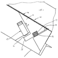
도 1은 본 발명의 잠금기구(10)가 설치되는 공지의 형태의 퀵커플러(A)를 보여준다. 퀵커플러(A)는 이곳에 결합된 유압장치에 의해 유압으로 작동한다. 퀵커플러의 몸체(B)의 장착점(C)이 굴삭기(도시 안됨)의 아암에 연결된다. Fig. 1 shows a known quick coupler A in which the
몸체(B)의 후크(D)에 부착물(도시 안됨)의 장착핀이 결합된다. 부착물의 다른 장착핀은 요홈부(E)에 위치한다. 유압식 웨지(F)가 늘어나면서 요홈부(E)의 장착핀을 잠궈 부착물을 퀵커플러(A)에 결합한다.The attachment pin of the attachment (not shown) is engaged with the hook D of the body B. [ Another attachment pin of the attachment is located in the recessed portion E. The hydraulic wedge F is stretched to engage the attachment with the quick coupler A by locking the mounting pin of the groove E.
따라서, 퀵커플러(A)의 유압이 잘못되면 웨지(F)가 줄어들어 장착핀이 요홈부(E)에서 풀리고, 후크(D)내에 다른 핀이 없으면, 부착물이 굴삭기 아암에서 떨어질 수 있다. 그러나, 후크(D)내에 핀이 있으면, 부착물이 퀵커플러(A)에서 완전히 분리되지 않고 후크(D)에 있는 핀에 걸려 흔들릴 것이다. Therefore, if the hydraulic pressure of the quick coupler A is incorrect, the wedge F is reduced so that the mounting pin is loosened in the recessed portion E, and if there is no other pin in the hook D, the attachment can fall from the excavator arm. However, if there is a pin in the hook D, the attachment will not shake off completely in the quick coupler A but will shake off the pin in the hook D.
도 1에 도시된 형태의 퀵커플러(A)에서, 웨지(F)는 웨지의 신축을 제어하는 유압실린더(G)로 이루어진 작동수단의 일부분이다. 이런 유압실린더(G)와 웨지(F)의 구성은 일례를 든 것일 뿐이다.In the quick coupler A of the type shown in Fig. 1, the wedge F is a part of an operating means consisting of a hydraulic cylinder G for controlling the expansion and contraction of the wedge. The construction of the hydraulic cylinder G and the wedge F is merely an example.
여기서는 퀵커플러(A)의 실린더(G)와 웨지(F)의 경계부에 잠금기구(10)가 설치되지만, 이는 본 발명의 잠금기구를 퀵커플러에 결합하는 예를 보여줄 뿐이다. 다른 실시예에 대해서는 도 6~22를 참조하여 뒤에 설명한다.Here, the
도 2~3에 의하면, 잠금기구(10)가 잠금요소인 래치(11), 유압식 선형 액튜에이터로서의 작동기인 실린더(12), 및 기계식 바이어싱 요소인 스프링(13)를 포함한다. 실린더(12)는 웨지(F)가 후퇴했을 때 유압으로 작동한다(도 4 참조). 기계식 바이어싱 요소가 래치(11)를 제1 방향(X)으로 움직인다. 2 to 3, the
래치(11)는 거의 쐐기 형태이고, 퀵커플러 몸체(B)에 대해 고정된 표면과 래치(11)의 표면이 슬라이딩 인터페이스(14)를 형성하는데, 이에 대해서는 뒤에 자세히 설명한다. 래치(11)의 고정된 표면(16)에 대해 실린더가 작용한다. 따라서, 도 1~5의 제1 실시예에서는 실린더(12)가 표면(16)에 맞물릴 수 있다.The
스프링(13)의 일단부는 래치(11)의 포켓(17)에 위치하고, 타단부는 고정 표면(18)에 맞닿는다.One end of the
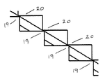
인터페이스(14)의 한쪽을 형성하는 래치(11)의 표면에 톱니(19)가 형성되고, 이 톱니(19)는 퀵커플러의 웨지(F)에 결합되는 맞은편 톱니(20)에 맞물린다(도 3 참조). 톱니(20)는 웨지(F)나 쐐기작용 실린더(G)의 일부분에 연결되는 요소의 일부분일 수 있지만, 쐐기(F)에 대한 톱니(20)의 결합은 본 발명에서는 중요치 않고, 중요한 것은 톱니(20)가 쐐기(F)와 같이 움직이는 것이다.A
도 3에 2 톱니(19,20)의 구성이 도시되었지만, 다르게 구성될 수도 있다.Although the configuration of the two
이들 톱니(19,20)는 웨지(F)가 작동위치로 신장했을 때 톱니(20)가 접촉각 때문에 톱니(19) 위로 움직이도록 구성된다. 도 3은 톱니(20)가 톱니(19) 위로 움직이는 상태를 보여준다. 웨지(F)가 신장할 때는 래치(11)는 스프링(13)의 장력을 거슬러 자유롭게 움직이도록 되어있어, 2 톱니(19,20)가 서로 맞물리지 않고 움직여 래치(11)가 쐐기(F)의 신장을 방해하지 않는다. These
쐐기(F)가 신장된 위치로 완전히 움직였으면, 스프링(13)이 래치(11)를 X 방향으로 움직여, 2 톱니(19,20)가 맞물려 쐐기(F)를 신장된 위치로 잠근다. When the wedge F has fully moved to the extended position, the
정상 동작상태에서, 퀵커플러를 제어하여 웨지(F)를 후퇴시킬 수 있다. 유압을 이중동작 실린더(G)의 후퇴측에 가하면, 이 실린더(G)가 작동자인 실린더(12)에 압력을 가한다. 실린더(12)가 해제기(26)쪽으로 뻗어 숄더(15)의 표면(16)을 밀면, 래치(11)가 스프링(13)의 힘을 거슬러 Y 방향으로 움직인다. In the normal operating state, the quick coupler can be controlled to retract the wedge F. When the hydraulic pressure is applied to the retreat side of the double action cylinder G, the cylinder G applies pressure to the
도 1~5의 실시예에서, 래치(11)가 표면(18)으로 형성된 스토퍼인 정지면에 접촉한다. 래치(11)가 정지면(18)에 걸리면, 양 톱니(19,20) 사이에 틈새(Z)가 형성되어, 웨지(F)가 자유롭게 후퇴할 수 있다(도 3 참조). In the embodiment of Figures 1-5, the
그러나, 언제라도 퀵커플러에 대한 유압이 잘못되어 웨지 실린더(G)에 대한 압력이 없어지고 웨지(F)가 더이상 이중작동 실린더(G)에 의해 (신장된) 작동위치로 고정되지 못해도, 스프링(13)이 계속해서 슬라이딩 인터페이스(14)를 따라 잠금부재를 X방향으로 움직여, 화살표(21) 방향으로 압축력이 작용하여 양 톱니(19,20)가 맞물리게 되어, 웨지(F)를 신장위치로 계속 잠그게 된다. However, even if the hydraulic pressure to the quick coupler is lost at any time and the pressure on the wedge cylinder G is lost and the wedge F is no longer fixed to the operating position (extended) by the double operating cylinder G, Continues to move the locking member along the sliding
그 결과, 웨지(F)가 화살표(22) 방향으로 후퇴하지 못하게 되므로, 유압이 잘못되어도 웨지(F)는 연결핀을 계속해서 요홈부(E)에 머물게 한다.As a result, the wedge F is prevented from retreating in the direction of the
따라서, 유압공급이 잘못되어도 잠금기구(10)가 웨지(F)를 신장된 위치로 잠궈 잠금효과를 상실하지 않는다. Therefore, even if the hydraulic pressure supply is wrong, the
부하를 실린더(12)로 되돌리는 톱니의 갯수와 미끄럼 각도로 인한 압축부하 때문에, 양 톱니(19,20)를 비교적 작게할 수 있는데, 이는 잠금기구의 백래시가 아주 작고 무한히 가변적인 잠금위치를 효과적으로 생성할 수 있음을 의미한다. 그 결과, 웨지(F)가 어떤 신장위치에 있어도 웨지(F)를 잠글 수 있다. 또, 톱니(20)가 톱니(19)의 거의 전부와 맞물리게 된다.20 can be made relatively small owing to the number of teeth and the compression load due to the sliding angle of returning the load to the
도 1에 도시된 퀵커플러 종류에서는 잠금기구의 위치가 웨지실린더(G)와 웨지 인터페이스 사이에 있어서, 기존의 퀵커플러 제품에 대한 신규 키트로도 가능하다. 이런 키트를 현장에서 조립할 수 있다. 따라서, 본 발명의 잠금기구는 전술한 종류의 퀵커플러에만 사용할 수 있는 것이 아니다. In the type of quick coupler shown in Fig. 1, the position of the lock mechanism is also possible with a new kit for a conventional quick coupler product, between the wedge cylinder G and the wedge interface. These kits can be assembled in the field. Therefore, the locking mechanism of the present invention can not be used only for the quick coupler of the kind described above.
도 6~22는 본 발명의 두번째 실시예로서, 앞의 예와의 유일한 차이점은 웨지(F) 밑에 잠금기구가 하나가 아니라 실린더(G)와 웨지(F) 양쪽에 2개의 잠금기구가 있다는 것이다. 그외 다른 대응 요소들은 동일한 번호로 표시한다.Figures 6 to 22 show a second embodiment of the present invention in which the only difference from the previous example is that there is not one lock mechanism under the wedge F but two lock mechanisms on both the cylinder G and the wedge F . The other corresponding elements are marked with the same number.
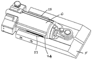
도 6의 퀵커플러(A)는 몸체(B)의 한쪽 측판을 제거하여 유압실린더(G)와 웨지(F)를 노출시키고 잠금기구(10)를 보여준다.The quick coupler A in Fig. 6 shows the
도 7에 의하면, 웨지(F)에서 양갈래로 갈라진 다리(28)의 오목한 내면(27)에 체결구로 결합되는 캐치(23)의 일부분이 톱니(20)임을 알 수 있다. 잠금기구(10)는 웨지(F)의 각각의 다리(28)에 연결된다. 7, it can be seen that the
마찬가지로, 실린더(G) 양쪽의 요홈부(29)에 구동요소(24)와 래치(11)가 설치된다. 래치(11)에는 톱니(19)가 형성된다.The driving
본 실시예의 잠금기구(10)가 2개이지만 편의상 하나에 대해서만 설명한다. Although there are two locking
도 7은 하우징(30)의 양쪽에 설치되고 해제기(26)가 달린 한쌍의 작동 실린더(12) 각각이 2개의 잠금기구(10)의 각각의 래치(11)에 어떻게 작용하는지를 보여준다. 7 shows how each of a pair of actuating
도 10~13은 실린더(G)의 단면도들인데, 도 10은 톱니(19,20)가 잠금상태가 아니라 완전히 떨어져 있는 상태로서 제1 실시예에서 설명한 틈새(Z)를 볼 수 있다. 래치(11)의 대부분의 톱니부는 일련의 구동면(31,32)과 정지면(33,34)을 형성하고 구동요소(24)의 대응 톱니부와 맞물리며, 요홈부(29)의 일단부에 정지면(18)이 형성된다(도 11~12 참조).Figs. 10 to 13 are sectional views of the cylinder G, and Fig. 10 shows the gap Z described in the first embodiment in a state in which the
도 14와 19~22에서 알 수 있듯이, 래치(11)의 포켓(17)에 설치되는 스프링(13)은 정지면(34')에 작용한다.14 and 19 to 22, the
구동요소(24)에 의한 래치(11)의 종횡 운동은 래치(11)의 안내 슬롯(37,38)에 맞물리는 구동요소(24)의 비스듬한 안내 레일(35,36)에 의해 조절된다(도 14~16 참조). 이런 레일(35,36)은 래치의 슬롯(37,38)과 맞물려, 해제기(26)가 래치(11)의 뒷면(38)을 밀 때 해제과정을 보조한다. 슬롯면이 레일을 타고 미끄러지면서 래치(11)가 구동면(31,32)과 스프링(13)에 의해 제어된 방향으로 뒷쪽으로 당겨진다. 이 경우, 웨지(F)가 신장할 때 일어나는 걸쇠효과를 보조하여, 래치(11)의 움직임이 톱니(19,20) 사이에서 평행하고 일정하게 일어나게 된다.The longitudinal and lateral movement of the
도 17~18은 래치(1)가 도 17의 "후퇴" 상태(풀림상태)에서 도 18의 "신장" 상태(맞물린 상태)로 어떻게 움직이고, 슬롯(37)을 갖춘 래치(11) 부분과 레일(35)이 어떻게 작용하는지를 보여준다.17-18 show how the
도 19~22는 포켓(17)내 스프링(13)을 보여주는 단면도로서, 실린더(12)의 해제기(26)가 래치(11)의 표면(39)에 맞닿아 래치(11)를 해제상태로 어떻게 되돌리는지를 보여준다. 도 7에 보이는 해제기(26) 자체의 복귀스프링(40)에 의해 유압이 풀렸을 때 해제기(26)가 래치(11)의 접촉면(39)에서 떨어진다(도 19 참조). 이때는 스프링(13)만이 래치(11)의 움직임에 관여한다.19-22 are sectional views showing the
이 실시예는 제1 실시예와 같은 식으로 작용한다. 따라서, 예컨대 도 10에서는 래치(11)가 완전히 후퇴한(풀림) 위치로 움직이면 틈새(Z)에 의해 웨지(F)가 아무런 간섭 없이, 즉 톱니(19,20)가 서로 접촉하지 않은채 움직이게 된다.This embodiment works in the same manner as the first embodiment. 10, for example, when the
도 11은 캐치(23)의 후퇴로 톱니(19,20)가 맞물려 잠금기구(10)가 맞물리고, 캐치(23)가 다시 전진하지 않는한 래치(11)는 더이상 풀림위치로 전진하지 않는 위치의 톱니(19,20)를 보여준다. Figure 11 shows a position where the
도 12는 톱니(19,20)가 완전히 잠금상태로 맞물린 것을 보여준다. 캐치(23)가 후퇴하면 래치(11)가 구동요소(24)를 더 뒤로 구동하여 웨지(F)를 제자리에 잠근다.Fig. 12 shows that the
잠금기구를 구성하는 3개의 메인 요소인 래치(11), 구동요소(24) 및 캐치(23) 외에 스프링(13)은 바이어스 요소이다. 도시된 실시예들은 일례일 뿐이고, 각 부분들은 교체가 가능하지만, 조립된 퀵커플러 안에 설치될 수 있다. In addition to the
본 발명의 특징은 구동요소(24)에서의 래치(11)의 이동 각도와 톱니(19,20)의 각도 사이의 관계에 있다. 래치(11)는 30°각도로 움직이고 톱니(19,20)는 45°각도로 세팅되는 것이 바람직하다. 작동중에, 톱니(19,20)의 정면이 서로 접촉하면 잠금상태로 맞닿게 된다. 이어서, 캐치(23)가 잠금상태로 충분히 후퇴하면(잠금상태는 2개의 톱니(19,20)가 영구적으로 서로 맞물린 상태임), 톱니 사이의 교차 각도관계 때문에 톱니들이 더이상 분리될 수 없다. 이때문에, 캐치(23)가 전진할 때까지는 잠금기구(10)가 잠금상태를 유지하고 분리가 일어날 수 없다. 이 상태가 도 11에 도시되었다.A feature of the invention lies in the relationship between the angle of movement of the
본 발명의 잠금기구는 유압이 고장나도 퀵커플러에 설치된 부착물을 작동위치에 유지하도록 동작할 수 있다.
The lock mechanism of the present invention can operate to maintain the attachment installed in the quick coupler in the operating position even if the hydraulic pressure fails.
Claims (22)
이동식 잠금요소;
잠금요소를 제1 방향으로 움직이도록 힘을 가하는 바이어싱 수단; 및
바이어싱 수단에 대해 잠금요소를 움직이는 작동기;를 포함하고,
상기 잠금요소가 결합수단을 갖고, 이 결합수단은 잠금요소가 바이어싱 수단에 의해 제1 방향으로 움직일 때 퀵커플러의 이동식 웨지요소에 결합된 다른 결합요소와 결합하여 웨지요소를 움직이지 않게 잠그는 것을 특징으로 하는 잠금기구.CLAIMS 1. A lock mechanism for a quick coupler comprising:
Removable locking elements;
Biasing means for applying a force to move the locking element in the first direction; And
And an actuator for moving the locking element relative to the biasing means,
The locking element has a coupling means which engages with another coupling element coupled to the movable wedge element of the quick coupler to lock the wedge element immovably when the locking element is moved in the first direction by the biasing means Features a locking mechanism.
상기 잠금요소가 결합수단을 갖고, 작동수단에 대한 유압공급이 고장날 경우 잠금요소가 제1 방향으로 바이어싱 수단에 의해 움직이도록 허용되었을 때 상기 결합수단은 이동식 요소와 결합하여 이동식 요소가 움직이지 못하게 잠그는 것을 특징으로 하는 퀵커플러. A movable wedge element, actuating means for moving the movable wedge element, a movable locking element, biasing means for urging the locking element to move in the first direction, and an actuator for immovably locking the locking element in the first direction;
When the locking element has engagement means and the locking element is allowed to move by the biasing means in the first direction when the hydraulic supply to the actuating means fails, the engaging means engages with the movable element to prevent the movable element from moving Wherein the first and second couplers are coupled to each other.
Applications Claiming Priority (3)
| Application Number | Priority Date | Filing Date | Title |
|---|---|---|---|
| NZ60411012 | 2012-12-10 | ||
| NZ604110 | 2012-12-10 | ||
| PCT/NZ2013/000219 WO2014092584A1 (en) | 2012-12-10 | 2013-12-04 | A locking mechanism |
Publications (1)
| Publication Number | Publication Date |
|---|---|
| KR20150094691A true KR20150094691A (en) | 2015-08-19 |
Family
ID=50934716
Family Applications (1)
| Application Number | Title | Priority Date | Filing Date |
|---|---|---|---|
| KR1020157018180A KR20150094691A (en) | 2012-12-10 | 2013-12-04 | A locking mechanism |
Country Status (6)
| Country | Link |
|---|---|
| US (1) | US20150322646A1 (en) |
| EP (1) | EP2931981A4 (en) |
| JP (1) | JP2016500410A (en) |
| KR (1) | KR20150094691A (en) |
| AU (1) | AU2013360409A1 (en) |
| WO (1) | WO2014092584A1 (en) |
Families Citing this family (5)
| Publication number | Priority date | Publication date | Assignee | Title |
|---|---|---|---|---|
| JP7041059B2 (en) * | 2015-12-07 | 2022-03-23 | ウェッジロック・エクイップメント・リミテッド | Locking device for quick couplers |
| GB2610148B (en) * | 2018-06-25 | 2023-08-09 | Miller Uk Ltd | Coupler |
| JP7481020B2 (en) * | 2018-11-30 | 2024-05-10 | ヒューズ・アセット・グループ・ピーティーワイ・リミテッド | coupler |
| US11208785B2 (en) * | 2018-12-12 | 2021-12-28 | Caterpillar Inc. | Tool coupling arrangement having zero offset |
| US10975544B1 (en) * | 2020-04-27 | 2021-04-13 | Caterpillar Inc. | Work tool coupling assembly with locking wedge |
Family Cites Families (14)
| Publication number | Priority date | Publication date | Assignee | Title |
|---|---|---|---|---|
| JPH086833Y2 (en) * | 1993-11-09 | 1996-02-28 | 敬植 山田 | Hydraulic excavator adapter |
| US5727342A (en) * | 1996-04-18 | 1998-03-17 | Wain-Roy, Inc. | Hydraulic latch pin assembly for coupling a tool to a construction equipment |
| EP0975840B1 (en) * | 1997-04-14 | 2001-03-07 | Baumaschinentechnik Gesellschaft mbH | Device for attaching interchangeable items of equipment rapidly, for an excavator |
| GB2330570B (en) * | 1998-09-08 | 1999-09-15 | Miller Ronald Keith | Quick coupler for bucket excavators |
| AU723305B1 (en) * | 1999-03-03 | 2000-08-24 | Barry Koster | Adaptor hitch with locking pin |
| JP4309018B2 (en) * | 2000-04-20 | 2009-08-05 | ヤンマー株式会社 | Attachment drop-off prevention structure for turning work vehicles |
| US7306395B2 (en) * | 2001-11-29 | 2007-12-11 | Jrb Attachments, Llc | Spread-style coupler with supplemental lock system |
| EP2087178A2 (en) * | 2006-09-04 | 2009-08-12 | Miller UK Limited | Coupler |
| CA2590464A1 (en) * | 2007-05-30 | 2008-11-30 | Brandt Industries Ltd. | Quick coupling mechanism for tool attachment |
| GB0720413D0 (en) * | 2007-10-18 | 2007-11-28 | Monaghan Conor | A Coupler |
| AT507598B1 (en) * | 2008-12-05 | 2012-03-15 | Wacker Neuson Linz Gmbh | DEVICE FOR REPLACEABLE TOOLS |
| WO2011040824A1 (en) * | 2009-09-29 | 2011-04-07 | Doherty Engineered Attachments Limited | A coupler |
| KR101811461B1 (en) * | 2009-12-09 | 2017-12-21 | 에스 티 커플러스 리미티드 | Improvements relating to couplers |
| CA2733965A1 (en) * | 2011-03-14 | 2012-09-14 | Brandt Industries Ltd. | Compact quick coupling mechanism for tool attachment |
-
2013
- 2013-12-04 US US14/650,858 patent/US20150322646A1/en not_active Abandoned
- 2013-12-04 EP EP13861826.9A patent/EP2931981A4/en not_active Withdrawn
- 2013-12-04 WO PCT/NZ2013/000219 patent/WO2014092584A1/en active Application Filing
- 2013-12-04 KR KR1020157018180A patent/KR20150094691A/en not_active Application Discontinuation
- 2013-12-04 AU AU2013360409A patent/AU2013360409A1/en not_active Abandoned
- 2013-12-04 JP JP2015547886A patent/JP2016500410A/en active Pending
Also Published As
| Publication number | Publication date |
|---|---|
| US20150322646A1 (en) | 2015-11-12 |
| WO2014092584A1 (en) | 2014-06-19 |
| EP2931981A1 (en) | 2015-10-21 |
| EP2931981A4 (en) | 2016-11-02 |
| AU2013360409A1 (en) | 2015-07-23 |
| JP2016500410A (en) | 2016-01-12 |
Similar Documents
| Publication | Publication Date | Title |
|---|---|---|
| KR20150094691A (en) | A locking mechanism | |
| JP6490722B2 (en) | Slide rail assembly | |
| US9670642B2 (en) | Coupler for coupling attachments to excavation machines | |
| CN107614796B (en) | Visual indicator for a coupling | |
| AU2016365527B2 (en) | A locking device for a quick coupler | |
| JP6357211B2 (en) | Driving mechanism and driving method for furniture part | |
| EP3502354B1 (en) | Fail-safe device for quick coupler | |
| TWI700056B (en) | Slide rail assembly | |
| US11952737B2 (en) | Coupler for coupling an attachment to a dipper arm | |
| TWI702019B (en) | Slide rail assembly | |
| JP2019093103A (en) | Slide rail assembly and rail kit thereof | |
| CA3166525A1 (en) | Quick coupler | |
| KR101737019B1 (en) | Quick hitch coupler for backhoe bucket | |
| KR20240005978A (en) | Quick coupler | |
| JP2016500410A5 (en) | ||
| JP6941706B2 (en) | Slide rail assembly and its rail kit | |
| US20160251820A1 (en) | Work tool assembly and coupler | |
| CN114847691B (en) | Sliding rail assembly | |
| IES86256B2 (en) | A safety mechanism for a coupler for coupling an accessory to a dipper arm. | |
| NZ618597B2 (en) | A locking mechanism | |
| CN202764806U (en) | Hasp lock of electric car | |
| JP5678082B2 (en) | Gauge variable chassis equipment | |
| CN112089232B (en) | Sliding rail assembly | |
| NZ727394B2 (en) | A Locking Device for a Quick Coupler | |
| WO2022258190A1 (en) | Multi-part telescope |
Legal Events
| Date | Code | Title | Description |
|---|---|---|---|
| WITN | Application deemed withdrawn, e.g. because no request for examination was filed or no examination fee was paid |