JP7041059B2 - Locking device for quick couplers - Google Patents
Locking device for quick couplers Download PDFInfo
- Publication number
- JP7041059B2 JP7041059B2 JP2018529159A JP2018529159A JP7041059B2 JP 7041059 B2 JP7041059 B2 JP 7041059B2 JP 2018529159 A JP2018529159 A JP 2018529159A JP 2018529159 A JP2018529159 A JP 2018529159A JP 7041059 B2 JP7041059 B2 JP 7041059B2
- Authority
- JP
- Japan
- Prior art keywords
- wedge
- locking element
- pin
- quick coupler
- mounting member
- Prior art date
- Legal status (The legal status is an assumption and is not a legal conclusion. Google has not performed a legal analysis and makes no representation as to the accuracy of the status listed.)
- Active
Links
Images


Classifications
-
- E—FIXED CONSTRUCTIONS
- E02—HYDRAULIC ENGINEERING; FOUNDATIONS; SOIL SHIFTING
- E02F—DREDGING; SOIL-SHIFTING
- E02F3/00—Dredgers; Soil-shifting machines
- E02F3/04—Dredgers; Soil-shifting machines mechanically-driven
- E02F3/28—Dredgers; Soil-shifting machines mechanically-driven with digging tools mounted on a dipper- or bucket-arm, i.e. there is either one arm or a pair of arms, e.g. dippers, buckets
- E02F3/36—Component parts
- E02F3/3604—Devices to connect tools to arms, booms or the like
- E02F3/3609—Devices to connect tools to arms, booms or the like of the quick acting type, e.g. controlled from the operator seat
- E02F3/364—Devices to connect tools to arms, booms or the like of the quick acting type, e.g. controlled from the operator seat using wedges
-
- E—FIXED CONSTRUCTIONS
- E02—HYDRAULIC ENGINEERING; FOUNDATIONS; SOIL SHIFTING
- E02F—DREDGING; SOIL-SHIFTING
- E02F3/00—Dredgers; Soil-shifting machines
- E02F3/04—Dredgers; Soil-shifting machines mechanically-driven
- E02F3/28—Dredgers; Soil-shifting machines mechanically-driven with digging tools mounted on a dipper- or bucket-arm, i.e. there is either one arm or a pair of arms, e.g. dippers, buckets
- E02F3/36—Component parts
- E02F3/3604—Devices to connect tools to arms, booms or the like
- E02F3/3609—Devices to connect tools to arms, booms or the like of the quick acting type, e.g. controlled from the operator seat
- E02F3/3627—Devices to connect tools to arms, booms or the like of the quick acting type, e.g. controlled from the operator seat with a hook and a longitudinal locking element
-
- E—FIXED CONSTRUCTIONS
- E02—HYDRAULIC ENGINEERING; FOUNDATIONS; SOIL SHIFTING
- E02F—DREDGING; SOIL-SHIFTING
- E02F3/00—Dredgers; Soil-shifting machines
- E02F3/04—Dredgers; Soil-shifting machines mechanically-driven
- E02F3/28—Dredgers; Soil-shifting machines mechanically-driven with digging tools mounted on a dipper- or bucket-arm, i.e. there is either one arm or a pair of arms, e.g. dippers, buckets
- E02F3/36—Component parts
- E02F3/3604—Devices to connect tools to arms, booms or the like
- E02F3/3609—Devices to connect tools to arms, booms or the like of the quick acting type, e.g. controlled from the operator seat
- E02F3/3645—Devices to connect tools to arms, booms or the like of the quick acting type, e.g. controlled from the operator seat with auto-engagement means for automatic snap-on of the tool coupler part
-
- E—FIXED CONSTRUCTIONS
- E02—HYDRAULIC ENGINEERING; FOUNDATIONS; SOIL SHIFTING
- E02F—DREDGING; SOIL-SHIFTING
- E02F3/00—Dredgers; Soil-shifting machines
- E02F3/04—Dredgers; Soil-shifting machines mechanically-driven
- E02F3/28—Dredgers; Soil-shifting machines mechanically-driven with digging tools mounted on a dipper- or bucket-arm, i.e. there is either one arm or a pair of arms, e.g. dippers, buckets
- E02F3/36—Component parts
- E02F3/3604—Devices to connect tools to arms, booms or the like
- E02F3/3609—Devices to connect tools to arms, booms or the like of the quick acting type, e.g. controlled from the operator seat
- E02F3/3663—Devices to connect tools to arms, booms or the like of the quick acting type, e.g. controlled from the operator seat hydraulically-operated
Landscapes
- Engineering & Computer Science (AREA)
- Mechanical Engineering (AREA)
- Mining & Mineral Resources (AREA)
- Civil Engineering (AREA)
- General Engineering & Computer Science (AREA)
- Structural Engineering (AREA)
- Shovels (AREA)
- Quick-Acting Or Multi-Walled Pipe Joints (AREA)
- Details Of Connecting Devices For Male And Female Coupling (AREA)
- Mutual Connection Of Rods And Tubes (AREA)
- Connection Of Plates (AREA)
- Snaps, Bayonet Connections, Set Pins, And Snap Rings (AREA)
Description
本発明は、クイック・カプラのための係止デバイスに関する。 The present invention relates to a locking device for a quick coupler.
取付け部材、例えばバケットを、掘削機等の土壌作業機械に組み付けるクイック・カプラは公知である。クイック・カプラに関する潜在的な危険性は、カプラが、取付け部材をクイック・カプラに組み付ける組付け点の一方又は両方で、取付け部材を保持できないおそれがあることである。したがって、取付け部材は、(組付け点のそれぞれで結合していない場合)カプラから脱落するか、又はカプラからぶら下がる(即ち、組付け点の一方の周りに揺動する)ことがある。取付け部材上の組付け点は、典型的には、いわゆるピンによって形成され、これらのピンは、クイック・カプラの合体点の凹部内に嵌合し、次に、凹部内で係止される。 Quick couplers that attach mounting members, such as buckets, to soil work machines such as excavators are known. A potential danger with the quick coupler is that the coupler may not be able to hold the mounting member at one or both of the assembly points at which the mounting member is assembled to the quick coupler. Therefore, the mounting member may drop off the coupler (if not coupled at each of the assembly points) or hang from the coupler (ie, swing around one of the assembly points). Assembly points on the mounting member are typically formed by so-called pins, which fit into the recesses at the coalescing points of the quick coupler and then lock in the recesses.
カプラを掘削機等の土壌作業機械に組み付ける際、オペレータに最も近い端部を本明細書では「前端部」と呼ぶ。したがって、前端部で凹部/合体点に嵌合する取付け部材のピンを本明細書では「前ピン」と呼ぶ。同様に、カプラのもう一方の端部を「後端部」と呼び、カプラの中に嵌合する取付け部材のピンを「後ピン」と呼ぶ。 When assembling a coupler to a soil work machine such as an excavator, the end closest to the operator is referred to herein as the "front end". Therefore, the pin of the mounting member that fits into the recess / coalescence point at the front end is referred to herein as the "front pin". Similarly, the other end of the coupler is referred to as the "rear end" and the pin of the mounting member fitted into the coupler is referred to as the "rear pin".
取付け部材を適切な位置に正確に保持できないのは、様々な理由に起因し得る。例えば、クイック・カプラが、液圧式に動作する摺動くさび構成要素によって後ピンを保持するタイプのものである場合、液圧の不良により、クイック・カプラが取付け部材を作動位置に保持できなくなる。このことは、典型的には、後ピンがくさび構成要素の傾斜先頭表面上に負荷を加え、これにより、ピンがクイック・カプラ内でもはや係止されない位置までくさびを「後方に」駆動させることに起因する。したがって、取付け部材は、前ピンの軸周りにカプラからぶら下がることになる。 The inability to accurately hold the mounting member in place can be due to a variety of reasons. For example, if the quick coupler is of the type that holds the rear pin by a hydraulically operating sliding wedge component, poor hydraulic pressure will prevent the quick coupler from holding the mounting member in the working position. This typically causes the rear pin to load onto the tilted leading surface of the wedge component, thereby driving the wedge "backward" to a position where the pin is no longer locked in the quick coupler. caused by. Therefore, the mounting member will hang from the coupler around the axis of the front pin.
前ピンが係止デバイスによって保持されていない場合、取付け部材は、カプラから完全に脱落することがある。本発明者等の特許文献1では、安全係止デバイスを開示しており、この安全係止デバイスは、後ピンの解放をもたらす不良の際に、前ピンをカプラ内に保持する。したがって、取付け部材は、前ピンの軸周りにカプラからぶら下がるだけである。
If the front pin is not held by the locking device, the mounting member may drop completely from the coupler.
したがって、本発明の目的は、クイック・カプラの係止デバイスのためのくさび係止要素を提供することであり、このくさび係止要素は、くさびによって保持されるピンが、(液圧不良の際に)ピンがもはやカプラによって保持されない位置までくさびを駆動する傾向を少なくとも低減するか、又は有用な選択を世間に少なくとも提供するようなものである。 Therefore, it is an object of the present invention to provide a wedge locking element for a locking device of a quick coupler, which wedge locking element is such that the pins held by the wedge (in the event of poor hydraulic pressure). It is like at least reducing the tendency to drive the wedge to a position where the pin is no longer held by the coupler, or at least providing the world with a useful choice.
この目的を達成する本発明の概念は、広範には、ピンに対してある向きを有するくさびの先頭端部にあり、くさびは、ピンがくさびに負荷を加えてくさびを解放位置まで駆動する可能性を少なくとも低減するような係止関係で、ピンと係合する。 The concept of the present invention that achieves this object is broadly located at the front end of a wedge that has an orientation with respect to the pin, which allows the pin to load the wedge and drive the wedge to the open position. Engage with the pin in a locking relationship that at least reduces the property.
広範には、本発明の一態様によれば、取付け部材のピンを土壌作業機械に結合するクイック・カプラの係止デバイスのためのくさび係合要素を提供し、くさび係止要素は、傾斜くさび表面を含み、くさび表面から突出するのは、係合表面であり、取付け部材のピンは、係合表面と係合することができるが、くさび係止要素を適切な位置に維持する力が不足する際、くさび係止要素に実質的な駆動力を加えることが一切なく、これにより、ピンは、くさび表面によってカプラにくさび結合する。 Broadly, according to one aspect of the invention, a wedge engaging element for a quick coupler locking device that couples a pin of a mounting member to a soil work machine is provided, the wedge locking element being a tilted wedge. It is the engaging surface that includes the surface and protrudes from the wedge surface, and the pins of the mounting member can engage the engaging surface, but lack the force to keep the wedge locking element in place. In doing so, no substantial driving force is applied to the wedge locking element, whereby the pin is wedge-coupled to the coupler by the wedge surface.
広範には、本発明の第2の態様によれば、係止デバイスは、前記駆動力が不足する際、ピン係合表面でピンを保持するように動作可能なクランプ・デバイスを更に含む。 Broadly speaking, according to a second aspect of the invention, the locking device further includes a clamping device that can operate to hold the pin at the pin engaging surface when the driving force is insufficient.
本発明の好ましい形態では、ピン係合表面は、くさびの遠位先頭部に位置し、くさびの遠位先頭部を形成する。 In a preferred embodiment of the invention, the pin engagement surface is located at the distal head of the wedge and forms the distal head of the wedge.
本発明の好ましい形態では、ピン係合表面は、実質的に平坦である。 In a preferred embodiment of the invention, the pin engagement surface is substantially flat.
好ましい形態では、ピン係合表面は、使用中、係止要素が駆動力によって移動する方向と実質的に一致する平面内にある。 In a preferred embodiment, the pin engagement surface is in a plane that substantially coincides with the direction in which the locking element is driven by the driving force during use.
好ましい形態では、駆動力は、液圧式である。 In a preferred embodiment, the driving force is hydraulic.
好ましくは、くさび係止要素は、液圧線形アクチュエータに結合するように構成し、より好ましくは、くさび係止要素は、液圧アクチュエータの一部を形成する。 Preferably, the wedge locking element is configured to be coupled to the hydraulic linear actuator, more preferably the wedge locking element forms part of the hydraulic actuator.
本発明の好ましい形態では、クランプ・デバイスは、くさび係止要素に組み付ける。 In a preferred embodiment of the invention, the clamp device is assembled to a wedge locking element.
好ましくは、本発明の1つの形態では、クランプ・デバイスは、枢動軸周りに枢動可能であるように組み付けたアームを含み、アームは、枢動軸から遠位であるピン係合部分を組み込む。 Preferably, in one embodiment of the invention, the clamp device comprises an arm assembled to be pivotable around a pivot axis, the arm having a pin engagement portion distal to the pivot axis. Incorporate.
本発明の好ましい形態では、アームは、付勢手段によって付勢する。本発明の好ましい形態では、付勢手段は、ばねである。 In a preferred embodiment of the invention, the arm is urged by urging means. In a preferred embodiment of the invention, the urging means is a spring.
本発明の第3の広範な態様によれば、取付け部材のピンを土壌作業機械に結合するクイック・カプラを提供し、カプラは、くさび係止要素と、本発明の上記の第2の広範な態様で述べたクランプ・デバイスとの組合せを含む。 According to a third broad aspect of the invention, there is provided a quick coupler that couples the pins of the mounting member to the soil work machine, the coupler being a wedge locking element and the above-mentioned second broad spectrum of the invention. Includes a combination with the clamp device described in the embodiment.
好ましくは、くさび係止要素は、摺動するようにクイック・カプラ内に保持し、クランプ・デバイスは、くさび係止要素と共に移動するように組み付ける。 Preferably, the wedge locking element is slidably held in the quick coupler and the clamp device is assembled to move with the wedge locking element.
本発明の一実施形態、及びクイック・カプラへの実施形態の適用に関する以下のより詳細な説明では、本明細書の一部を形成する図面を参照されたい。 For the following more detailed description of an embodiment of the invention and the application of embodiments to quick couplers, see the drawings that form part of this specification.
クイック・カプラの1つの形態に関して、本発明の態様を本明細書で説明するが、他の形態のクイック・カプラを使用し得ることは当業者であれば理解されよう。 Although aspects of the invention are described herein with respect to one form of the quick coupler, it will be appreciated by those skilled in the art that other forms of the quick coupler may be used.
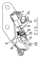
図面の図1及び図2に示すクイック・カプラは、本発明者等が製造した公知の形態のクイック・カプラAである。クイック・カプラAは、カプラを取り付ける機械(通常は土壌作業機械)の液圧技術によって液圧式に動作する。カプラ本体Bは、組付け点Cを有し、これにより、カプラを、例えば掘削機のアーム(図示せず)に取り付けることができる。 The quick couplers shown in FIGS. 1 and 2 of the drawings are the quick couplers A of a known form manufactured by the present inventors and the like. The quick coupler A operates hydraulically by the hydraulic technology of the machine to which the coupler is attached (usually a soil work machine). The coupler body B has an assembly point C, which allows the coupler to be attached to, for example, an excavator arm (not shown).
カプラ本体Bは、フック形状前凹部Dを有し、この前凹部D内に、取付け部材の前組付けピンP1が係合する。上述のように、クイック・カプラのフック形状凹部の端部は、典型的には、カプラの「前」と呼ぶ。というのは、この端部が、機械(例えば掘削機)のオペレータの方に向くことになるカプラの端部であるためである。 The coupler body B has a hook-shaped front recess D, and the front assembly pin P1 of the mounting member is engaged in the front recess D. As mentioned above, the end of the hook-shaped recess of the quick coupler is typically referred to as the "front" of the coupler. This is because this end is the end of the coupler that will face the operator of the machine (eg excavator).
組付け部の後組付けピンP2は、後凹部Eに位置する。 The rear assembly pin P2 of the assembly portion is located in the rear recess E.
カプラのこの形態では、くさび構成要素である移動可能係止要素F(以下、簡単にするために「くさびF」)は、取付け部材の後組付けピンP2を後凹部内に捕捉するように拡張可能である。くさびFには、液圧で動力を供給する。 In this form of the coupler, the movable locking element F (hereinafter, "wedge F" for simplicity), which is a wedge component, expands to capture the rear assembly pin P2 of the mounting member in the rear recess. It is possible. Power is supplied to the wedge F by hydraulic pressure.
典型的には、掘削機のオペレータは、カプラの凹部Dを取付け部材の前ピンP1上に配置し、次に、後ピンP2が凹部E内に係合するようにカプラを押し込める。次に、くさびFを拡張し、後凹部E内で後ピンP2と係合させ、係止する。カプラAによって係合したピンP1及びP2を図1に示す。これにより、取付け部材は、作動位置でカプラAに結合している。 Typically, the excavator operator places the recess D of the coupler on the front pin P1 of the mounting member and then pushes the coupler so that the rear pin P2 engages in the recess E. Next, the wedge F is expanded, engaged with the rear pin P2 in the rear recess E, and locked. Pins P1 and P2 engaged by the coupler A are shown in FIG. As a result, the mounting member is coupled to the coupler A at the operating position.
例えば、カプラAへの液圧力が不足する場合、くさびFをその係止位置に動かし保持する液圧シリンダGは、係止位置でくさびを保持することができない。その結果、くさびFは後退することがあり、組付けピンP2を凹部Eから解放可能にする(図2を参照)。 For example, when the hydraulic pressure on the coupler A is insufficient, the hydraulic cylinder G that moves and holds the wedge F to the locking position cannot hold the wedge at the locking position. As a result, the wedge F may recede, allowing the assembly pin P2 to be released from the recess E (see FIG. 2).
フック形状凹部又は合体部D内の前ピンP1が前凹部内に保持されていない場合、取付け部材は、カプラから脱落し、したがって、掘削機のアームから脱落することがある。しかし、前ピンP1が、(例えば本発明者等のニュージーランド特許明細書第552294号/第546893号に記載され、特許請求する本発明者等のI-LockデバイスLによって)保持されている場合、取付け部材は、カプラAから完全に脱落することはないが、ピンP1上にぶら下がることになる。 If the front pin P1 in the hook-shaped recess or coalescing portion D is not held in the front recess, the mounting member may fall off the coupler and thus from the arm of the excavator. However, if the front pin P1 is held (eg, by the inventor's I-Lock device L as described in New Zealand Patent Specification No. 552294/546893, claiming the inventor, etc.). The mounting member does not completely fall off the coupler A, but hangs on the pin P1.
図示のカプラAの形態において、くさびFは、液圧シリンダGによって形成する動作手段の一部であり、液圧シリンダGは、駆動力を加え、シリンダGのピストン・ロッドRを介してくさびFの拡張及び後退を制御する。このことは、シリンダG及びくさびF構成が取り得る形態の一例にすぎない。 In the form of the illustrated coupler A, the wedge F is a part of the operating means formed by the hydraulic cylinder G, and the hydraulic cylinder G applies a driving force to the wedge F via the piston rod R of the cylinder G. Controls expansion and retreat. This is only one example of the possible forms of the cylinder G and wedge F configurations.
図1及び図2に示すように、くさびFの先頭端部又は遠位端部は、傾斜又は勾配表面Mを含む。複合的に液圧が不足した場合、作動力により、ピンP2がくさびFを後方に駆動する(図1の矢印Yに示すように)。このことは、傾斜面M(及び図1に矢印Xによって示される、加えられた垂直な力)による。したがって、後ピンP2は、くさび面MがくさびFによって後凹部内でもはや保持されない点までくさび面Mを下げ(図2)、取付け部材は、上記した前ピンP1周りで自由に揺動することになる。 As shown in FIGS. 1 and 2, the leading or distal ends of the wedge F include a sloped or sloped surface M. When the hydraulic pressure is insufficient in a complex manner, the pin P2 drives the wedge F backward by the operating force (as shown by the arrow Y in FIG. 1). This is due to the inclined surface M (and the applied vertical force indicated by arrow X in FIG. 1). Therefore, the rear pin P2 lowers the wedge surface M to a point where the wedge surface M is no longer held in the rear recess by the wedge F (FIG. 2), and the mounting member freely swings around the front pin P1 described above. become.
所与の取付け部材に関して、ピンP1とP2との間の距離は、ピンの直径のように厳格に固定される。本明細書に示し、説明する実施形態では、クイック・カプラは、前凹部に対して、後凹部Eがもたらす範囲内にあるピン直径及びピン中心を有する取付け部材に応ずる。したがって、本発明のくさび係止要素は、多数の取付け部材のピン中心に適しているが、単一のピン中心設計にも等しく適用することができる。 For a given mounting member, the distance between pins P1 and P2 is as tightly fixed as the diameter of the pin. In the embodiments shown and described herein, the quick coupler responds to a mounting member having a pin diameter and pin center within the range provided by the rear recess E with respect to the anterior recess. Thus, the wedge locking elements of the present invention are suitable for pin centers of multiple mounting members, but are equally applicable to single pin center designs.
本発明によれば、本発明者等は、くさび10(くさび10の一例は図12から図15に示す)を考案しており、くさび10は、先頭端部に、突出部11を含み、突出部11は、実質的に平らな(平坦な)ピン係合表面12をもたらす。この平坦表面12は、傾斜くさび表面13の下側末端を越えて延在する。傾斜表面13と平坦表面12との間の角度は、鈍角である。
According to the present invention, the present inventors have devised a wedge 10 (an example of the
図12から図15に示すくさびの例の構成は、図1及び図2に示すタイプのカプラに特定のものである。(本発明により提供するような)くさびの先頭端部における平坦突出ピン係合表面12は、傾斜ピン係合表面を有するくさびの他のタイプ及び構成で組み込むことができることは当業者であれば理解されよう。
The configuration of the wedge example shown in FIGS. 12 to 15 is specific to the type of coupler shown in FIGS. 1 and 2. Those skilled in the art will appreciate that the flat protruding
ピン係合表面12の表面は、(矢印「X」で示す)カプラの不良状態においてピンP2がくさび10に加える力の方向に実質的に垂直である。したがって、ピンP2が傾斜くさび区分13の端部に到達すると、ピンP2が傾斜面13と係合している際に加える負荷と同様にくさび10に対し負荷を加えることは、もはや可能ではない。言い換えれば、くさびを矢印「Y」の方向で後方に駆動する負荷はない。
The surface of the
ピン係合表面12がある平面は、くさび係止要素が前後に移動する方向と実質的に一致することは理解されよう。
It will be appreciated that the plane on which the
後ピンP2がくさび10のピン係合表面12に到達すると、ピンP2とピン係合表面12との間の摩擦のために、くさび10に負荷を加えることが依然として可能である場合がある。この摩擦接触は、周期的なわずかな量で、くさび10を(方向Yで)後方に、ピンP2がくさびの極縁部21を通過し得る点まで移動させることがある。したがって、ピンP2は、凹部から離れてカプラから自由になることができ、このため、取付け部材がカプラから解放され、取付け部材をピンP1上で揺動可能にさせることになる。
Once the rear pin P2 reaches the
したがって、後ピンP2とくさび10との間の関係を実質的に保持する手段を追加することは、有利であり、図面は、そのような手段をクランプ・デバイス14の形態で示す。クランプ・デバイス14の存在により、くさび10が上述の量だけ後ろに移動した後、再度引き戻されることが保証される。というのは、ピンP2が、方向Yとは反対の方向に移動するためである。したがって、このクランプ・デバイス14は、ピンP2がくさび10のピン係合表面12の遠位端部21を越えて通過しカプラと分離することを防止するものである。
Therefore, it is advantageous to add means to substantially maintain the relationship between the rear pin P2 and the
本発明によれば、クランプ・デバイス14は、クランプ・デバイスを作動させるために更なる液圧アクチュエータを必要としない。このことは、費用を低減させるだけでなく、信頼性も向上させる。 According to the present invention, the clamp device 14 does not require an additional hydraulic actuator to operate the clamp device. This not only reduces costs, but also improves reliability.
クランプ・デバイス14は、適切な組付け部15によってくさび10に結合され、くさび10と共に移動可能であるようにする。これにより、クランプ14をくさび10に結合すると、クランプ14が、くさび10とピンP2とのあらゆるくさび固定位置で、ピンP2との適切な関係を保持できることが保証される。
The clamp device 14 is coupled to the
クランプ14の例示的形態では、クランプは、中実クランプ・アーム16を含む。例示の好ましい形態では、クランプ・アーム16は、実質的に円弧形状であり、一端17で組付け部15に枢動結合する。
In an exemplary embodiment of the clamp 14, the clamp comprises a
クランプ・アーム16は、付勢、好ましくはばね付勢され、したがって、一形態では、クランプ・アーム16は、(図示のような)圧縮ばね18又はねじりばね等の他の付勢手段によって付勢される。図示のように、ばね18は、枢動軸17から離間しているが隣接する点でクランプ・アーム16と係合する。ばね18のもう一方の端部は、組付け部15の交差部品19に結合する。
The
組付け部15は、上記のように、くさび10によって支持される。図示の形態では、組付け部15は、くさび10内に設けた、適切に成形された凹部15aの中に位置する。
The
クランプ・アーム16は、ピンP2が、ピンP2が凹部E内に入る移動の間、ばね18の付勢効果に反してクランプ・アーム16を強制的に移動できるような設計及び構成のものである。これにより、ピンP2が凹部内に移動するのを可能にするのに必要な間隙をもたらす。
The
したがって、例えば、クランプ・アーム16の先頭ピン接触部分20の外形は適切に決定され、(カプラAが取付け部材と係合する際)ピンP2が凹部E内に係合する間、及び(取付け部材をカプラAから分離する際)カプラから分離する間の両方で、先頭ピン接触部分20がピンP2と滑らかに押し込み式に係合し、ピンP2の上に載るようにする。
Thus, for example, the outer shape of the head
図3は、クランプ・アーム16の外形付き端部20を示し、外形付き端部20は、シリンダGの作用下、くさび10が拡張し始めるとピンP2に接近する。一方で、図4は、くさび10が拡張を続けるにつれて、クランプ・アーム16の端部20がピンP2と接触することを示す。くさび10が更に前進すると、クランプ・アーム16の端部20は、ピンP2の上に載る(図5及び図6を参照)。
FIG. 3 shows the outer
くさび10が前進し続けると(図7)、クランプ・アーム16に対するばね付勢により、端部20はピンP2の反対側に乗り越えて下がる。最終的に、くさび10が前進できるだけ遠くに拡張すると、後ピンP2がくさび10と凹部Eの対向表面との間で完全に係合するために、クランプ・アーム16は、ピンP2の上に、ピンと接触した状態で位置することになる(図8)。
As the
液圧シリンダGから入手可能な力は、付勢手段(例えばばね18)がもたらすクランプ・アーム16のクランプ力と比較すると非常に大きいものである。したがって、通常機能の間、ピンP2と係合及び解放する際、くさび10が移動すると、クランプ・アーム16は、ばね18の付勢に反して容易に移動する。したがって、クランプ・デバイス14を駆動又は作動させるために更なる液圧アクチュエータは必要としない。
The force available from the hydraulic cylinder G is very large compared to the clamping force of the clamping
図8は、係合位置におけるカプラAを示し、ピンP1及びP2、したがって、取付け部材はカプラ上に係止されている。この位置では、ピンP2は、後凹部E内にあり、くさび10は、シリンダGによって拡張され、ピンP2がくさび10(この場合傾斜表面13)と凹部Eの表面との間に保持されるようにする。
FIG. 8 shows the coupler A at the engagement position, where the pins P1 and P2, and thus the mounting member, are locked onto the coupler. In this position, the pin P2 is in the rear recess E so that the
より大きな直径のピンP2(図16を参照)の場合、図面は、ピンP2が、傾斜表面13及びピン係合表面12の両方に係合しているのを示すように見えるが、実際には、わずかな間隙がある。この間隙のために、ピン係合表面12と凹部Eの表面との間は、実質的に、同時に接触することはなく、これにより、係合/分離ごとに生じる摩耗を回避するようにする。
For the larger diameter pin P2 (see FIG. 16), the drawings appear to show that the pin P2 is engaged to both the
しかし、くさび10が、(例えば液圧がないために)ピンP2が分離し得る点まで後退した場合(図9又は図10を参照)、クランプ・アーム16の存在により、ピンP2とくさび10との間の関係を実質的に保持し、これにより、ピンP2をくさび10と係合した状態で自動的に保持する。したがって、カプラの不良モードでは、後ピンP2は、後凹部Eから外れる動きに反して保持されることになる。
However, if the
取付け部材のピンP1及びP2の保持は、前ピンP1が、上述した本発明者等のI-Lock安全係止デバイス等の保持手段によって保持されていることに依拠する。言い換えれば、前ピンP1は、図11に示すように、その通常位置と係止特徴(即ちI-Lock)との間のみを移動することができる。その結果、いずれか1つの取付け部材の前ピンP1と後ピンP2との間の固定距離のために、後ピンP2は、前ピンP1と同じ量だけ移動することができる。 The holding of the pins P1 and P2 of the mounting member depends on the front pin P1 being held by the holding means such as the above-mentioned I-Lock safety locking device of the present inventor or the like. In other words, the front pin P1 can only move between its normal position and the locking feature (ie, I-Lock), as shown in FIG. As a result, the rear pin P2 can be moved by the same amount as the front pin P1 due to the fixed distance between the front pin P1 and the rear pin P2 of any one mounting member.
当業者であれば、カプラ、及び特に後端部係止機構が、様々な直径のピンと作動し得ることは上記及び図面から理解されよう。図16は、2つの異なるピン直径、例えば、小さな直径のピン及び大きな直径のピンを示す。図17は、より小さなピンP2が、クランプ・アーム16の成形端部20のより近くに置かれているのを示す。
Those skilled in the art will appreciate from the above and the drawings that couplers, and in particular the rear end locking mechanism, can work with pins of various diameters. FIG. 16 shows two different pin diameters, eg, a small diameter pin and a large diameter pin. FIG. 17 shows that the smaller pin P2 is placed closer to the molded
この目的で、クランプ・アーム16の遠位端部の内部表面の形状及び構成は、好ましくは、より小さな直径のピンを、平坦区分12の遠位端部21からできるだけ遠くに保持するように成形される。このことは、大きな直径及び小さな直径のピンP2を示す図16及び図17にグラフィックに示し、より小さな直径のピンは、遠位縁部21のより近くに保持されている。したがって、より小さなピンP2は、より遠くに移動しなければならず、これにより、クランプ・デバイス14が加える負荷(即ちより多くのばね圧縮)をより高く生じさせる。
For this purpose, the shape and configuration of the internal surface of the distal end of the
上記の説明では、アーム16をクランプ・アーム16と呼ぶ。しかし、アーム16の形態及び機能は、当業者が理解するように、アーム16を「安全」アームとして記述できるようなものである。
In the above description, the
本発明は、修正に対してオープンである。例えば、ばね付きクランプ・アーム16は、ばね部材によって形成することができる。
The present invention is open to modifications. For example, the spring-loaded
本発明は、特定の実施形態として説明、例示しており、実施形態は、公知のタイプのクイック・カプラに関連して詳細に説明している。本発明の範囲をそのような詳細に限定するか又は何らかの形で限定することは本出願人の意図するものではない。 The present invention has been described and exemplified as specific embodiments, which are described in detail in the context of known types of quick couplers. It is not the applicant's intent to limit the scope of the invention to such details or in any way.
更なる利点及び修正は、当業者には直ちに明らかであろう。したがって、本発明は、そのより広範な態様において、特定の詳細、製造及び方法の代表的手段、並びに図示、説明した例示的な例に限定されるものではない。したがって、本出願人の一般的な発明概念の趣旨又は範囲から逸脱することなく、そのような詳細から逸脱することができる。 Further benefits and modifications will be immediately apparent to those of skill in the art. Accordingly, the invention is not limited in its broader aspects to the specific details, representative means of manufacture and method, and exemplary examples illustrated and described. Therefore, it is possible to deviate from such details without departing from the spirit or scope of the applicant's general concept of invention.
Claims (13)
を含み、前記係止デバイスは、
a.傾斜くさび表面およびこの傾斜くさび表面から突出するピン係合表面を含むくさび
係止要素であって、前記ピン係合表面は、前記くさび係止要素の遠位先頭部に位置し、かつ前記くさび係止要素が移動するように構成されている方向へ延在する平担面であり、前
記取付け部材のピンと前記くさび係止要素の前記ピン係合表面とが係合する係止位置に前記くさび係止要素を維持するために必要な駆動力が不足する際、前記くさび係止要素を動かす実質的な負荷を前記くさび係止要素に加えることなく前記取付け部材のピンが前記くさび係止要素の前記ピン係合表面と係合するように構成されている、くさび係止要素、
b.前記ピン係合表面で前記取付け部材のピンを保持するように動作可能なクランプ・
デバイス、
を含み、
前記くさび係止要素は、前記クイック・カプラに摺動可能に保持され、前記クランプ・
デバイスは、前記くさび係止要素とともに移動可能に取り付けられる、クイック・カプラ
。 A quick coupler that couples the pins of a mounting member to a soil work machine, including a locking device, said locking device.
a. A wedge locking element comprising an inclined wedge surface and a pin engaging surface projecting from the inclined wedge surface, wherein the pin engaging surface is located at the distal head of the wedge locking element and is said to be a wedge. A flat bearing surface extending in a direction configured to move the stop element , the wedge at a locking position where the pin of the mounting member and the pin engaging surface of the wedge locking element engage. When the driving force required to maintain the locking element is insufficient, the pins of the mounting member engage the wedge locking element without applying a substantial load to the wedge locking element to move the wedge locking element. A wedge locking element, configured to engage the pin engaging surface of the stop element,
b. A clamp that can operate to hold the pin of the mounting member on the pin engaging surface.
device,
Including
The wedge locking element is slidably held by the quick coupler and the clamp.
The device is a quick coupler that is movably attached with the wedge locking element.
に記載のクイック・カプラ。 1. The wedge locking element is configured to be coupled to a hydraulic linear actuator.
Quick coupler as described in.
ック・カプラ。 The quick coupler according to claim 2, wherein the wedge locking element forms a part of a hydraulic actuator.
結合し、前記クランプ・デバイスは、前記くさび係止要素を前記係止位置で維持する駆動力が不足する際、前記取付け部材のピンを前記ピン係合表面で保持するように動作可能である、請求項1に記載のクイック・カプラ。 The mounting member pins are wedge-coupled to the quick coupler by the tilted wedge surface, and the clamping device is the mounting member when the driving force to maintain the wedge locking element in the locking position is insufficient. The quick coupler according to claim 1, wherein the pin can be operated to hold the pin on the pin engaging surface.
ック・カプラ。 The quick coupler according to claim 4, wherein the clamp device is assembled to the wedge locking element.
み、前記アームは、前記枢動軸から遠位であるピン係合部分を組み込む、請求項5に記載
のクイック・カプラ。 5. The clamp device comprises an arm assembled so as to be pivotable around a pivot axis, wherein the arm incorporates a pin engagement portion distal to the pivot axis, claim 5. Quick coupler.
ク・カプラ。 The quick coupler according to claim 4, wherein the wedge locking element is coupled to a hydraulic linear actuator.
・カプラは、係止デバイス、及びクランプ・デバイスを含み、前記係止デバイスは、傾斜
くさび表面を含むくさび係止要素を有し、前記くさび係止要素は、摺動するように前記ク
イック・カプラ内に保持され、前記傾斜くさび表面から突出するのは、ピン係合表面であり、前記ピン係合表面は、平担面であってかつ前記くさび係止要素の遠位先頭部を形成し
、さらに前記くさび係止要素が移動するように構成されている方向と実質的に一致する面
内にあり、前記ピン係合表面がこのように構成されることで、前記取付け部材のピンと前記くさび係止要素の前記ピン係合表面とが係合する係止位置に前記くさび係止要素を維持するために必要な駆動力が不足する際、前記くさび係止要素を動かす実質的な負荷を前記くさび係止要素に加えることなく前記取付け部材のピンが前記ピン係合表面と係合できるように構成され、前記クランプ・デバイスは、前記駆動力が不足する場合に、前記ピン係合表面で前記取付け部材のピンを保持するように動作可能であり、前記クランプ・デバイスは、前記くさび係止要素と共に移動するように組み付ける、クイック・カプラ。 A quick coupler that couples the pins of a mounting member to a soil work machine, the quick coupler comprising a locking device, and a clamping device, wherein the locking device is a wedge locking element including a slanted wedge surface. The wedge locking element is held in the quick coupler so as to slide, and it is the pin engaging surface that protrudes from the inclined wedge surface, and the pin engaging surface is flat. It is in a plane that is a carrying surface and that forms the distal head portion of the wedge locking element and that is substantially in line with the direction in which the wedge locking element is configured to move. With the mating surface configured in this way, it is necessary to maintain the wedge locking element at the locking position where the pin of the mounting member and the pin engaging surface of the wedge locking element engage. When the driving force is insufficient, the pins of the mounting member are configured to engage the pin engaging surface without applying a substantial load to the wedge locking element to move the wedge locking element . The clamping device can operate to hold the pins of the mounting member on the pin engaging surface when the driving force is insufficient, and the clamping device moves with the wedge locking element. A quick coupler that can be assembled like this.
あるように組み付けたアームを含み、前記アームは、付勢手段によって付勢し、前記枢動
軸から遠位であるピン係合部分を組み込む、請求項11に記載のクイック・カプラ。 The clamp device includes an arm assembled to the wedge locking element so that it can be pivoted around a pivot axis, the arm being urged by urging means and far from the pivot axis. The quick coupler according to claim 11, which incorporates a pin engagement portion that is a position.
Applications Claiming Priority (3)
| Application Number | Priority Date | Filing Date | Title |
|---|---|---|---|
| NZ714945 | 2015-12-07 | ||
| NZ71494515 | 2015-12-07 | ||
| PCT/NZ2016/050189 WO2017099610A1 (en) | 2015-12-07 | 2016-12-01 | A locking device for a quick coupler |
Publications (3)
| Publication Number | Publication Date |
|---|---|
| JP2019501314A JP2019501314A (en) | 2019-01-17 |
| JP2019501314A5 JP2019501314A5 (en) | 2020-01-16 |
| JP7041059B2 true JP7041059B2 (en) | 2022-03-23 |
Family
ID=59013475
Family Applications (1)
| Application Number | Title | Priority Date | Filing Date |
|---|---|---|---|
| JP2018529159A Active JP7041059B2 (en) | 2015-12-07 | 2016-12-01 | Locking device for quick couplers |
Country Status (7)
| Country | Link |
|---|---|
| US (2) | US11846083B2 (en) |
| JP (1) | JP7041059B2 (en) |
| CN (1) | CN108431334B (en) |
| AU (1) | AU2016365527B2 (en) |
| CA (1) | CA3007341A1 (en) |
| GB (1) | GB2560847B (en) |
| WO (1) | WO2017099610A1 (en) |
Families Citing this family (6)
| Publication number | Priority date | Publication date | Assignee | Title |
|---|---|---|---|---|
| JP7189200B2 (en) | 2017-08-04 | 2022-12-13 | ウェッジロック・エクイップメント・リミテッド | quick coupler |
| GB2576487A (en) * | 2018-06-25 | 2020-02-26 | Miller Uk Ltd | Coupler Horseshoe |
| CN110512676B (en) * | 2019-08-22 | 2021-04-13 | 温州金茂建设有限公司 | Multifunctional front end connector for excavator |
| US11702816B2 (en) | 2020-01-30 | 2023-07-18 | Wedgelock Equipment Limited | Quick coupler |
| WO2022026778A1 (en) * | 2020-07-29 | 2022-02-03 | Cascade Corporation | l-LOCK COUPLER |
| US20240018739A1 (en) | 2022-07-18 | 2024-01-18 | Caterpillar Inc. | Anti-Release Mechanism |
Citations (6)
| Publication number | Priority date | Publication date | Assignee | Title |
|---|---|---|---|---|
| JP2001303608A (en) | 2000-04-20 | 2001-10-31 | Yanmar Diesel Engine Co Ltd | Connecting device for attachment |
| JP2004124382A (en) | 2002-09-30 | 2004-04-22 | Kobelco Contstruction Machinery Ltd | Work machine and its attachment mounting device |
| WO2006083172A1 (en) | 2005-02-04 | 2006-08-10 | Gjerstad Mek. Industri As | Quick coupling device for a work tool |
| WO2009110808A1 (en) | 2008-03-07 | 2009-09-11 | Wedgelock Equipment Limited | Coupler for earth moving or materials handling machine |
| WO2011035883A1 (en) | 2009-09-22 | 2011-03-31 | Ian Hill | Hydraulic coupler with pin retention system for coupling an attachment to a work machine |
| US20130318841A1 (en) | 2012-05-30 | 2013-12-05 | Troy Curtis Robl | Tool coupler system having multiple pressure sources |
Family Cites Families (52)
| Publication number | Priority date | Publication date | Assignee | Title |
|---|---|---|---|---|
| US3065977A (en) * | 1960-10-28 | 1962-11-27 | Int Harvester Co | Three point implement attaching hitch mechanism |
| US3531140A (en) * | 1968-01-26 | 1970-09-29 | Int Harvester Co | Tractor quick hitch attachment |
| NZ199611A (en) * | 1981-02-05 | 1984-09-28 | Maroochy Shire Council | Quick release and attachment assembly for construction equipment tools |
| US5107610A (en) * | 1991-01-22 | 1992-04-28 | Nicholas Fusco | Quick-coupling connector for backhoes and the like |
| US5147173A (en) * | 1991-06-03 | 1992-09-15 | Caterpillar Inc. | Coupling device |
| US5179794A (en) * | 1991-12-26 | 1993-01-19 | Ballinger Jon C | Semi-automatic coupling apparatus |
| DE4410194A1 (en) | 1994-03-24 | 1995-10-05 | Karl Heinz Josef Leh | Attachable mounting and fastening device for a tool, an excavator bucket or the like can be attached to the extension arm of a tillage tool, excavator or the like. |
| US6233852B1 (en) * | 1998-01-12 | 2001-05-22 | Pemberton, Inc. | Universal coupler for excavator buckets |
| GB2330569B (en) * | 1998-09-08 | 1999-09-15 | Miller Ronald Keith | Coupler for bucket excavators |
| US6866467B2 (en) * | 2000-11-29 | 2005-03-15 | Caterpillar S.A.R.L. | Hydraulically actuated quick coupling device |
| US6699001B2 (en) * | 2000-12-11 | 2004-03-02 | Jrb Company, Inc. | Coupler with improved pin lock |
| US6691438B2 (en) * | 2001-04-26 | 2004-02-17 | Jrb Company, Inc. | Coupler with improved structure and method for manufacturing same |
| AUPR533701A0 (en) | 2001-05-29 | 2001-06-21 | Ephemere Pty Ltd | A coupling assembly |
| EP1318242B1 (en) * | 2001-12-06 | 2006-10-11 | Geith Patents Limited | a quick hitch coupler for coupling an accessory to a dipper arm and the quick hitch coupler comprising a control system |
| ITBO20030056A1 (en) * | 2003-02-07 | 2004-08-08 | Cangini Benne Srl | TOOL CONNECTION DEVICE. |
| US7086821B1 (en) * | 2005-01-31 | 2006-08-08 | L & R Manufacturing Llc | Quick attachment arrangement for end loader |
| CN104563186A (en) * | 2006-04-20 | 2015-04-29 | 卡特彼勒公司 | Quick coupler |
| CA2590464A1 (en) | 2007-05-30 | 2008-11-30 | Brandt Industries Ltd. | Quick coupling mechanism for tool attachment |
| GB0720413D0 (en) * | 2007-10-18 | 2007-11-28 | Monaghan Conor | A Coupler |
| GB0816335D0 (en) | 2008-09-08 | 2008-10-15 | Hill Ian | Coupler with gravity operated safety device |
| WO2010059948A1 (en) * | 2008-11-20 | 2010-05-27 | Jrb Attachments, Llc | Coupler with secondary lock on front hook |
| US7866935B1 (en) * | 2008-12-11 | 2011-01-11 | TAG Manufacturing, Inc. | Manually operated coupler |
| US8662817B2 (en) * | 2009-01-08 | 2014-03-04 | Paladin Brands Group, Inc. | Coupler with safety cam |
| GB2467380B (en) * | 2009-02-03 | 2010-12-22 | Miller Int Ltd | Fully automatic coupler for excavator arm |
| CN101550706A (en) | 2009-04-30 | 2009-10-07 | 徐州巴特工程机械制造有限公司 | Hydraulic rotary quick change adapter connector of excavator-type shovel clamshell excavator |
| US9206582B2 (en) | 2009-09-29 | 2015-12-08 | Doherty Engineered Attachments Limited | Coupler |
| GB2474576B (en) * | 2009-10-16 | 2014-03-19 | Ian Hill | Coupler |
| AU2010328742B2 (en) * | 2009-12-09 | 2016-06-09 | Hughes Asset Group Pty Ltd | Improvements relating to couplers |
| US8585345B2 (en) * | 2010-03-26 | 2013-11-19 | Paladin Brands Group, Inc. | Coupler with pivoting front hook lock |
| GB2497965A (en) * | 2011-12-22 | 2013-07-03 | Miller Int Ltd | Coupler for Attaching an Accessory to an Excavator Arm |
| US8869437B2 (en) * | 2012-05-30 | 2014-10-28 | Caterpillar Inc. | Quick coupler |
| US8684623B2 (en) * | 2012-05-30 | 2014-04-01 | Caterpillar Inc. | Tool coupler having anti-release mechanism |
| WO2014058380A1 (en) * | 2012-10-08 | 2014-04-17 | Indexator Group Ab | Apparatus for connecting an appliance/tool and a method therefor |
| JP2016500410A (en) * | 2012-12-10 | 2016-01-12 | ウェッジロック・エクイップメント・リミテッド | Lock mechanism |
| US20140212210A1 (en) * | 2013-01-25 | 2014-07-31 | Caterpillar Inc. | Tool coupler having a modular frame construction |
| KR101338036B1 (en) | 2013-03-07 | 2013-12-11 | 주식회사 필엔지니어링 | Automatic safety device for quick coupler |
| US20140294497A1 (en) * | 2013-04-02 | 2014-10-02 | Caterpillar Inc. | Locking system for quick coupler |
| US20140308061A1 (en) * | 2013-04-16 | 2014-10-16 | Caterpillar Inc. | Method and System for Detecting Engagement with a Work Tool Accessory |
| DE202013004797U1 (en) | 2013-05-23 | 2014-08-25 | Kinshofer Gmbh | Quick coupler |
| KR20160041944A (en) | 2013-08-30 | 2016-04-18 | 볼보 컨스트럭션 이큅먼트 에이비 | Quick coupler for construction machine |
| AU2014337788A1 (en) * | 2013-10-22 | 2016-06-09 | Doherty Engineered Attachments Limited | Improvements in and relating to couplers |
| WO2016153360A1 (en) * | 2015-03-25 | 2016-09-29 | Wedgelock Equipment Limited | A visual indicator for a coupler |
| GB2554306B (en) * | 2015-06-04 | 2019-10-23 | Rangi Hart Gerome | A coupler |
| EP3502354B1 (en) * | 2016-08-18 | 2021-05-12 | Daemo Engineering Co., Ltd. | Fail-safe device for quick coupler |
| US11041284B2 (en) * | 2017-02-20 | 2021-06-22 | Cnh Industrial America Llc | System and method for coupling an implement to a work vehicle |
| JP7189200B2 (en) | 2017-08-04 | 2022-12-13 | ウェッジロック・エクイップメント・リミテッド | quick coupler |
| JP6430671B1 (en) * | 2018-03-15 | 2018-11-28 | 丸山 俊 | Construction machine attachment mounting jig and construction machine |
| US11208785B2 (en) * | 2018-12-12 | 2021-12-28 | Caterpillar Inc. | Tool coupling arrangement having zero offset |
| JP7142601B2 (en) * | 2019-04-11 | 2022-09-27 | 株式会社クボタ | Work implement mounting mechanism and work vehicle |
| US11702816B2 (en) * | 2020-01-30 | 2023-07-18 | Wedgelock Equipment Limited | Quick coupler |
| US10975544B1 (en) * | 2020-04-27 | 2021-04-13 | Caterpillar Inc. | Work tool coupling assembly with locking wedge |
| WO2022026778A1 (en) * | 2020-07-29 | 2022-02-03 | Cascade Corporation | l-LOCK COUPLER |
-
2016
- 2016-12-01 AU AU2016365527A patent/AU2016365527B2/en active Active
- 2016-12-01 CA CA3007341A patent/CA3007341A1/en active Pending
- 2016-12-01 GB GB1810260.8A patent/GB2560847B/en active Active
- 2016-12-01 WO PCT/NZ2016/050189 patent/WO2017099610A1/en active Application Filing
- 2016-12-01 JP JP2018529159A patent/JP7041059B2/en active Active
- 2016-12-01 US US15/782,010 patent/US11846083B2/en active Active
- 2016-12-01 CN CN201680071542.5A patent/CN108431334B/en active Active
-
2023
- 2023-11-06 US US18/502,915 patent/US20240068196A1/en active Pending
Patent Citations (6)
| Publication number | Priority date | Publication date | Assignee | Title |
|---|---|---|---|---|
| JP2001303608A (en) | 2000-04-20 | 2001-10-31 | Yanmar Diesel Engine Co Ltd | Connecting device for attachment |
| JP2004124382A (en) | 2002-09-30 | 2004-04-22 | Kobelco Contstruction Machinery Ltd | Work machine and its attachment mounting device |
| WO2006083172A1 (en) | 2005-02-04 | 2006-08-10 | Gjerstad Mek. Industri As | Quick coupling device for a work tool |
| WO2009110808A1 (en) | 2008-03-07 | 2009-09-11 | Wedgelock Equipment Limited | Coupler for earth moving or materials handling machine |
| WO2011035883A1 (en) | 2009-09-22 | 2011-03-31 | Ian Hill | Hydraulic coupler with pin retention system for coupling an attachment to a work machine |
| US20130318841A1 (en) | 2012-05-30 | 2013-12-05 | Troy Curtis Robl | Tool coupler system having multiple pressure sources |
Also Published As
| Publication number | Publication date |
|---|---|
| CN108431334B (en) | 2021-07-30 |
| GB2560847B (en) | 2020-02-19 |
| JP2019501314A (en) | 2019-01-17 |
| AU2016365527A1 (en) | 2018-06-28 |
| US20240068196A1 (en) | 2024-02-29 |
| US11846083B2 (en) | 2023-12-19 |
| WO2017099610A1 (en) | 2017-06-15 |
| GB201810260D0 (en) | 2018-08-08 |
| CN108431334A (en) | 2018-08-21 |
| US20180355579A1 (en) | 2018-12-13 |
| AU2016365527B2 (en) | 2022-04-21 |
| CA3007341A1 (en) | 2017-06-15 |
| GB2560847A (en) | 2018-09-26 |
Similar Documents
| Publication | Publication Date | Title |
|---|---|---|
| JP7041059B2 (en) | Locking device for quick couplers | |
| CN107614796B (en) | Visual indicator for a coupling | |
| CA2232447C (en) | Improved back-up power tongs | |
| US7306395B2 (en) | Spread-style coupler with supplemental lock system | |
| US9677245B2 (en) | Coupler | |
| CA2590464A1 (en) | Quick coupling mechanism for tool attachment | |
| CN102089549B (en) | Wedge and socket assembly | |
| US20080289394A1 (en) | Compression jaw set with failure mode preventing reuse | |
| US20030099507A1 (en) | Spread-style coupler | |
| KR20210124196A (en) | coupler | |
| US8528239B2 (en) | Quick coupling device for connecting a tool to a handling equipment, such as the arm of an excavator | |
| JP5266060B2 (en) | Safety device for hydraulic coupling | |
| JP6656163B2 (en) | Hydraulic cylinder cover | |
| IES20130069A2 (en) | A safety mechanism for a coupler for coupling an accessory to a dipper arm. | |
| NZ727394B2 (en) | A Locking Device for a Quick Coupler | |
| US10995469B1 (en) | Quick coupler | |
| KR101650129B1 (en) | Crusher | |
| KR102353169B1 (en) | Quick coupler for excavator | |
| KR20160082311A (en) | Apparatus for connecting construction equipment and attachment | |
| IE20130069U1 (en) | A safety mechanism for a coupler for coupling an accessory to a dipper arm | |
| IES86256Y1 (en) | A safety mechanism for a coupler for coupling an accessory to a dipper arm | |
| JP2007203425A (en) | Cutting device |
Legal Events
| Date | Code | Title | Description |
|---|---|---|---|
| A521 | Request for written amendment filed |
Free format text: JAPANESE INTERMEDIATE CODE: A523 Effective date: 20191202 |
|
| A621 | Written request for application examination |
Free format text: JAPANESE INTERMEDIATE CODE: A621 Effective date: 20191202 |
|
| A131 | Notification of reasons for refusal |
Free format text: JAPANESE INTERMEDIATE CODE: A131 Effective date: 20200923 |
|
| A977 | Report on retrieval |
Free format text: JAPANESE INTERMEDIATE CODE: A971007 Effective date: 20200918 |
|
| A521 | Request for written amendment filed |
Free format text: JAPANESE INTERMEDIATE CODE: A523 Effective date: 20201223 |
|
| A131 | Notification of reasons for refusal |
Free format text: JAPANESE INTERMEDIATE CODE: A131 Effective date: 20210309 |
|
| A601 | Written request for extension of time |
Free format text: JAPANESE INTERMEDIATE CODE: A601 Effective date: 20210609 |
|
| A521 | Request for written amendment filed |
Free format text: JAPANESE INTERMEDIATE CODE: A523 Effective date: 20210806 |
|
| TRDD | Decision of grant or rejection written | ||
| A01 | Written decision to grant a patent or to grant a registration (utility model) |
Free format text: JAPANESE INTERMEDIATE CODE: A01 Effective date: 20220208 |
|
| A61 | First payment of annual fees (during grant procedure) |
Free format text: JAPANESE INTERMEDIATE CODE: A61 Effective date: 20220310 |
|
| R150 | Certificate of patent or registration of utility model |
Ref document number: 7041059 Country of ref document: JP Free format text: JAPANESE INTERMEDIATE CODE: R150 |