EP0975840B1 - Device for attaching interchangeable items of equipment rapidly, for an excavator - Google Patents
Device for attaching interchangeable items of equipment rapidly, for an excavator Download PDFInfo
- Publication number
- EP0975840B1 EP0975840B1 EP98914694A EP98914694A EP0975840B1 EP 0975840 B1 EP0975840 B1 EP 0975840B1 EP 98914694 A EP98914694 A EP 98914694A EP 98914694 A EP98914694 A EP 98914694A EP 0975840 B1 EP0975840 B1 EP 0975840B1
- Authority
- EP
- European Patent Office
- Prior art keywords
- rapid
- bar
- bolt
- safety bolt
- indicator device
- Prior art date
- Legal status (The legal status is an assumption and is not a legal conclusion. Google has not performed a legal analysis and makes no representation as to the accuracy of the status listed.)
- Expired - Lifetime
Links
Images


Classifications
-
- E—FIXED CONSTRUCTIONS
- E02—HYDRAULIC ENGINEERING; FOUNDATIONS; SOIL SHIFTING
- E02F—DREDGING; SOIL-SHIFTING
- E02F3/00—Dredgers; Soil-shifting machines
- E02F3/04—Dredgers; Soil-shifting machines mechanically-driven
- E02F3/28—Dredgers; Soil-shifting machines mechanically-driven with digging tools mounted on a dipper- or bucket-arm, i.e. there is either one arm or a pair of arms, e.g. dippers, buckets
- E02F3/36—Component parts
- E02F3/3604—Devices to connect tools to arms, booms or the like
- E02F3/3609—Devices to connect tools to arms, booms or the like of the quick acting type, e.g. controlled from the operator seat
- E02F3/3627—Devices to connect tools to arms, booms or the like of the quick acting type, e.g. controlled from the operator seat with a hook and a longitudinal locking element
-
- E—FIXED CONSTRUCTIONS
- E02—HYDRAULIC ENGINEERING; FOUNDATIONS; SOIL SHIFTING
- E02F—DREDGING; SOIL-SHIFTING
- E02F3/00—Dredgers; Soil-shifting machines
- E02F3/04—Dredgers; Soil-shifting machines mechanically-driven
- E02F3/28—Dredgers; Soil-shifting machines mechanically-driven with digging tools mounted on a dipper- or bucket-arm, i.e. there is either one arm or a pair of arms, e.g. dippers, buckets
- E02F3/36—Component parts
- E02F3/3604—Devices to connect tools to arms, booms or the like
- E02F3/3609—Devices to connect tools to arms, booms or the like of the quick acting type, e.g. controlled from the operator seat
- E02F3/364—Devices to connect tools to arms, booms or the like of the quick acting type, e.g. controlled from the operator seat using wedges
-
- E—FIXED CONSTRUCTIONS
- E02—HYDRAULIC ENGINEERING; FOUNDATIONS; SOIL SHIFTING
- E02F—DREDGING; SOIL-SHIFTING
- E02F3/00—Dredgers; Soil-shifting machines
- E02F3/04—Dredgers; Soil-shifting machines mechanically-driven
- E02F3/28—Dredgers; Soil-shifting machines mechanically-driven with digging tools mounted on a dipper- or bucket-arm, i.e. there is either one arm or a pair of arms, e.g. dippers, buckets
- E02F3/36—Component parts
- E02F3/3604—Devices to connect tools to arms, booms or the like
- E02F3/3609—Devices to connect tools to arms, booms or the like of the quick acting type, e.g. controlled from the operator seat
- E02F3/365—Devices to connect tools to arms, booms or the like of the quick acting type, e.g. controlled from the operator seat with redundant latching means, e.g. for safety purposes
-
- E—FIXED CONSTRUCTIONS
- E02—HYDRAULIC ENGINEERING; FOUNDATIONS; SOIL SHIFTING
- E02F—DREDGING; SOIL-SHIFTING
- E02F3/00—Dredgers; Soil-shifting machines
- E02F3/04—Dredgers; Soil-shifting machines mechanically-driven
- E02F3/28—Dredgers; Soil-shifting machines mechanically-driven with digging tools mounted on a dipper- or bucket-arm, i.e. there is either one arm or a pair of arms, e.g. dippers, buckets
- E02F3/36—Component parts
- E02F3/3604—Devices to connect tools to arms, booms or the like
- E02F3/3609—Devices to connect tools to arms, booms or the like of the quick acting type, e.g. controlled from the operator seat
- E02F3/3663—Devices to connect tools to arms, booms or the like of the quick acting type, e.g. controlled from the operator seat hydraulically-operated
Definitions
- the invention relates to a quick-change device for excavators, with which an attachment (attachment tool) on an excavator boom, e.g. a shovel or the like can be attached with the features of the introductory part of claim 1.
- an attachment attachment tool
- an excavator boom e.g. a shovel or the like
- Quick-change devices with hydraulic locking are known, in which a, for example conical, wedge of the quick-change device using a pressure medium cylinder, preferably a hydraulic cylinder, into a, possibly conical, Mount on the attachment, e.g. the spoon that is pushed.
- a quick change device with a securing element is out the US 5 467 542 A known. In its operative position, this prevents known securing element moving the bolt from the Quick change device out.
- the securing element is a Indicator pin connected to the position of the securing element (and not the latch) by pulling out of the quick-change device protrudes when the securing element is not in the active position is.
- the aim of the invention is to provide a fuse for quick-change devices, which has a simple construction and which is easy to use.
- the safety bolt can be replaced by a spring-loaded pressure cylinder, preferably hydraulic cylinder, be operable.
- a spring-loaded pressure cylinder preferably hydraulic cylinder
- the hydraulic cylinder by a spring is acted upon, its piston rod holding the safety pin can form so loaded that the locking bolt even at one Hydraulic defect does not recede. So this is backup the locking of the quick-change device takes effect automatically.
- the quick-change device The hydraulic circuit holding the locking cylinder can be opened again the quick-change device on the piston rod side acted to pull the bolt back, also used to act on the cylinder for the safety bolt in such a way that the safety bolt is pulled back, the (locking) Wedge backs away and the attachment (spoon) from the quick-change device can be uncoupled.
- the securing bolt which is transverse to the bolt the quick-change device can be pushed back and forth, even with a failure of the locking force (e.g. break of the adjusting spindle for the bolt) cannot withdraw from its active position.
- a failure of the locking force e.g. break of the adjusting spindle for the bolt
- the securing bolt is provided with a tab on a locking pin held in position by means of a folding pin can be.
- the invention is also based on the object, based on a quick-change device with the features of the introductory Parts of claims 13 or 14 to provide a quick-change device, which reliably indicates the position of the bolt.
- FIG. 1 shows a position in which the implement 2 on the quick-change device 1 only by means of the hooks 5 is coupled, the bolt 4 not yet in the receptacle 3 is introduced.
- the position in which the implement 2 with the Quick-change device 1 is coupled, is shown in Fig. 2.
- the latch 4 is in the receptacle 3 on the attachment 2nd inserted.
- the latch 4 is in a box-like Recording room of the quick-change device 1, consisting out of four walls 7, 8, 9 and 10 slidably guided.
- a pressure medium cylinder 11 (Locking cylinder), preferably a hydraulic cylinder, arranged inside the box-like receiving space and with the bolt 4 coupled.
- Safety bolt 15 is provided.
- the quick-change device 1 can, for example via the hydraulic circuit that the Locking cylinder 11 of the quick-change device 1 acted on the piston rod side, the cylinder 16 so be applied that the locking bolt 15 and the bolt 4 of the quick-change device 1 are withdrawn can.
- the attachment 2 can then by the quick-change device 1 can be removed.
- a safety bolt 15 can be provided which is mechanically, e.g. by hand is to be operated from.
- This (mechanical) embodiment of the securing bolt 15 is preferred, but not exclusively, for quick change devices 1 used, in which the bolt 4 is to be adjusted mechanically.
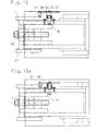
- a quick-change device 1 show FIGS. 8 to 11.
- an adjusting spindle 20 is provided with which the bolt 4 from the box-shaped recording space can be pulled out when on the quick-change device 1 to fix an attachment 2 is.
- the latch 4 by appropriate Actuate the adjusting spindle 20 again in the quick-change device 1 or their box-shaped receptacle pushed back.
- the securing bolt 15 is in the in FIGS. 11 and 12 embodiment shown through a hole in the side wall 10 of the box-shaped receiving space of the quick-change device 1 inserted bolt, which is connected to a tab 36 is, which has a hole 17 through which in its Active position pushed locking pin 15 on the outside the wall 10 attached pin 18 protrudes.
- a folding pin through a transverse hole 19 in pin 18 or a pin is pushed.
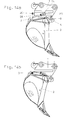
- FIGS. 6 and 7 show another embodiment a locking bolt 15, namely FIGS. 6 and 7 on Example of an actuable by means of a hydraulic cylinder 11 Riegel 4 and Fig. 13 using the example of one with a Spindle 20 operable bolt 4 of a quick-change device 1.
- Fig. 6 shows the locking pin 15 in its unlocked position (also Fig. 13 and 14) and Fig. 7 the securing bolt 15 in its the movement of the bolt 4 blocking operative position.
- Embodiment is the locking bolt 15 by a compression coil spring 25 in its operative position shown in FIG. 7 loaded, the compression coil spring 25 in one on the side wall 9 of the box-shaped receiving space the locking device 1 screwed housing 26 added is.
- a handle 27 which one facing inward Pin 28 carries.
- an operator attracts the handle 27 and rotates it so that the pin 28 on a console 21 of an attachment 2 rests (position according to 6 and 13).
- the quick-change device 1 In this position of the securing bolt 15 can the quick-change device 1 either by pressing of the locking cylinder 11 or the adjusting spindle 20 opened and the attachment 2 from the quick-change device 1 be removed. As soon as this is done, the spring presses 25 the locking bolt 15 in contact with the side surface of the bolt 4, with the free end of the pin 28 just next to the outside of the side wall 9 of the box-shaped receiving space the locking device 1 comes to rest.
- 15 and 16 is for a quick-change device 1 similar to that of Figs. 3 to 5 shown that the inventive Quick-change device 1 a locking control, a visual inspection of the position of the bolt 4 allowed, can be provided.
- 17 and 18 show this for a quick change device 1 with adjustment of the bolt 4 by the screw spindle 20.
- an indicator 30 is provided which is in line with the rear one End 14 of the bolt 4 is connected and as described above indicates the position of the bolt 4, so that a visual inspection the locked or unlocked position of the lock constantly, even from the cab of the excavator.
- the part of the indicator can be used to improve the visual inspection 30, the unlocked position of the bolt 4 from the Recording space of the quick-change device 1 protrudes in the signal color be painted so that it indicates "danger".
- the operative position of the bolt 4 only visible end surface 31 of the indicator 30 is preferably the same Colored like the quick-change device so that "No danger” is displayed and the correct locking between quick-change device 1 and attachment 2 is.
- the bolt 4 of the quick-change device 1 is by the Hydraulic cylinder 11 moved forward or backward.
- the advanced one (Extended) position of the cylinder 11 corresponds to that advanced, engaging in the receptacle 3 of the attachment 2 Bolt 4 of the quick-change device 1.
- the check valve 42 and the pressure reducing valve 41 are in a common valve block 40 included.
- Preload valve 45 installed, which only at a pressure of 80 bar opens.
- Two 3/2 way ball valves 43 and 46 are used to shut off the Hydraulic system, furthermore these 3/2 way valves 43 and 46 other hydraulic via the same hydraulic circuit controlled work equipment.
- an indicator shown in FIG. 20 30 this is designed as a round rod, which is in a sleeve 50 is led.
- the sleeve 50 is on the quick-change device attached so that the free end 31 of the indicator 30, so as shown in Fig. 18, for example is coming.
- Fig. 20 it is also shown that the interior of the Rifle in the area where the indicator 30 is on its side wall 32 is colored or painted with signal color, is set off, so that signal color when moving the indicator 30 is not damaged.
- a collar 52 is fastened via a screw 51, against which a compression coil spring 53 abuts, with their other end abuts a shoulder 54 in the sleeve 50.
- the bolt 4 of the quick-change device is one Bolted round rod 55, the 4 on the screw 51 of the indicator 30 and this in Fig. 20 moves to the left so that the free end of the indicator 30 and its area 32 painted with signal color is visible and, as before, for the other embodiments of the safety display device, indicates that the quick-change device is unlocked.
- a quick-change device 1 via which an attachment on The boom of an excavator can be attached in one provided in the quick-change device 1, box-shaped Guided recording room, a bolt 4, which in the locked position in a correspondingly shaped receptacle engages on the attachment.
- a hydraulic cylinder 11 is provided be, the piston rod coupled to the bolt 4 is.
- the bolt 4 can also be moved forward and backward by means of an adjusting spindle be pushed back.
- a safety bolt 15 provided that in its operative position against the Back 14 of the bolt 4 abuts and prevents this be pushed back into the quick-change device 1 can.
- a hydraulic cylinder is used to actuate the securing bolt 15 16 provided, the piston rod preferably immediately forms the securing bolt 15.
- the piston in the Hydraulic cylinder 16 is spring-loaded so that when depressurized Cylinder 16 of the locking pin 15 in its operative position is advanced. This ensures that if there is a drop in pressure in the hydraulic system of the safety bolts 15 in any case its active action is postponed.
- the latch 4 may be assigned a display device 30 which with bolt 4 advanced into its operative position the quick-change device 1 is included and the in its non-operative position retracted bolt 4 from the Quick-change device 1 protrudes.
Abstract
Description
Die Erfindung betrifft eine Schnellwechselvorrichtung für Bagger,
mit der an einem Baggerausleger ein Anbaugerät (Anbau-Werkzeug),
z.B. eine Schaufel od. dgl. befestigt werden kann, mit den Merkmalen
des einleitenden Teils von Anspruch 1.The invention relates to a quick-change device for excavators,
with which an attachment (attachment tool) on an excavator boom,
e.g. a shovel or the like can be attached with the features
of the introductory part of
Bekannt sind Schnellwechselvorrichtungen mit hydraulischer Verriegelung, bei welchen ein, beispielsweise konischer, Keil der Schnellwechselvorrichtung mit Hilfe eines Druckmittelzylinders, vorzugsweise eines Hydraulikzylinders, in eine, gegebenenfalls konische, Aufnahme am Anbaugerät, z.B. dem Löffel, geschoben wird.Quick-change devices with hydraulic locking are known, in which a, for example conical, wedge of the quick-change device using a pressure medium cylinder, preferably a hydraulic cylinder, into a, possibly conical, Mount on the attachment, e.g. the spoon that is pushed.
Es sind auch Schnellwechselvorrichtungen mit manueller Verriegelung bekannt, bei welchen der Riegel der Schnellwechselvorrichtung mit Hilfe einer Gewindespindel in die Aufnahme am Anbaugerät gezogen wird.They are also quick-change devices with manual locking known in which the latch of the quick-change device with A threaded spindle is pulled into the attachment on the attachment becomes.
Um zu verhindern, daß sich die Schnellwechselvorrichtungen unbeabsichtigt öffnen und sich die Verbindung zwischen Baggerausleger und Anbaugerät löst, sind Sicherheitsvorrichtungen bekannt.To prevent the quick-change devices from accidentally moving open and the connection between excavator boom and attachment triggers, safety devices are known.
Beispielsweise sind an den Schnellwechselvorrichtungen mit hydraulischer Verriegelung zwei Drei-Wege-Ventile vorgesehen, durch welche die Hydraulik deaktiviert werden kann, so daß ein unbeabsichtigtes Betätigen des Stellteils der Hydraulik nicht zu einem unbeabsichtigten Öffnen der Verriegelung der Schnellwechselvorrichtung führen kann.For example, on the quick-change devices with hydraulic Interlocking two three-way valves provided by which the hydraulics can be deactivated so that an accidental Do not operate the hydraulic control unit to an unintentional Guide open the lock of the quick-change device can.
Zusätzlich sind bei Schnellwechselvorrichtungen mechanische Sicherungen bekannt, welche die Form eines Tellers haben, der mittels einer Schraube am Riegel befestigt wird, so daß sich die Schnellwechselvorrichtung auch im Falle eines Defektes der Hydraulik (z.B. undichter Hydraulikzylinder und damit Nachlassen der Verriegelungskraft) nicht vom Anbaugerät lösen kann.In addition, there are mechanical fuses for quick-change devices known, which have the shape of a plate, which means a screw is attached to the bolt so that the quick-change device also in the event of a hydraulic defect (e.g. leaking hydraulic cylinder and thus a decrease in the locking force) cannot detach from the attachment.
Bei Schnellwechselvorrichtungen mit manueller Verriegelung sind zusätzlich zu einer Sicherung gegen das Verdrehen der Gewindespindel und damit das Lockern der Schnellwechselvorrichtung, die zuvor erwähnten Sicherungen, bestehend aus einem Teller und Schraube vorgesehen.For quick-change devices with manual locking are additional to prevent the threaded spindle from rotating and thus loosening the quick-change device that was previously mentioned fuses, consisting of a plate and screw intended.
Eine Schnellwechselvorrichtung mit einem Sicherungselement ist aus der US 5 467 542 A bekannt. In ihrer Wirkstellung verhindert das bekannte Sicherungselement das Verschieben des Riegels aus der Schnellwechselvorrichtung heraus. Mit dem Sicherungselement ist ein Anzeigestift verbunden, der die Stellung des Sicherungselementes (und nicht des Riegels) anzeigt, indem er aus der Schnellwechselvorrichtung vorsteht, wenn das Sicherungselement nicht in der Wirkstellung ist.A quick change device with a securing element is out the US 5 467 542 A known. In its operative position, this prevents known securing element moving the bolt from the Quick change device out. With the securing element is a Indicator pin connected to the position of the securing element (and not the latch) by pulling out of the quick-change device protrudes when the securing element is not in the active position is.
Ziel der Erfindung ist es, eine Sicherung für Schnellwechselvorrichtungen vorzusehen, die eine einfache Konstruktion besitzt und die einfach zu bedienen ist.The aim of the invention is to provide a fuse for quick-change devices, which has a simple construction and which is easy to use.
Erfindungsgemäß wird die Aufgabe mit den Merkmalen des Anspruches 1
gelöst.According to the invention the object with the features of
Bevorzugte und vorteilhafte Ausgestaltungen der Erfindung sind
Gegenstand der Unteransprüche 2 bis 12.Preferred and advantageous embodiments of the invention are
Subject of
Dadurch, daß bei der erfindungsgemäßen Schnellwechselvorrichtung als Sicherung ein vor- und zurückziehbarer (Sicherungs-) Bolzen vorgesehen ist, der in seiner Wirklage neben der vom in die Aufnahme am Anbaugerät (Werkzeug, z.B. Löffel) eingreifenden Ende des Riegels abgekehrten Seite angeordnet ist, wird ein unbeabsichtigtes Zurückschieben des Riegels und damit ein unbeabsichtigtes Lockern der Schnellwechselvorrichtung verhindert.The fact that in the quick-change device according to the invention as A retractable (retractable) bolt is provided for securing is in its active position next to that of the admission on Attachment (tool, e.g. spoon) engaging end of the latch opposite side is arranged, an unintentional pushing back of the bolt and thus an unintentional loosening of the Quick change device prevented.
Für die spezielle Ausführung des Sicherungsbolzens gibt es verschiedene Möglichkeiten. So kann der Sicherungsbolzen durch einen federbelasteten Druckmittelzylinder, vorzugsweise Hydraulikzylinder, betätigbar sein. Dadurch, daß der Hydraulikzylinder von einer Feder beaufschlagt ist, wird seine Kolbenstange, die den Sicherungsbolzen bilden kann, so belastet, daß der Verriegelungsbolzen auch bei einem Defekt der Hydraulik nicht zurückweicht. Damit ist diese Sicherung der Verriegelung der Schnellwechselvorrichtung automatisch wirksam.There are several for the special design of the safety bolt Possibilities. So the safety bolt can be replaced by a spring-loaded pressure cylinder, preferably hydraulic cylinder, be operable. The fact that the hydraulic cylinder by a spring is acted upon, its piston rod holding the safety pin can form so loaded that the locking bolt even at one Hydraulic defect does not recede. So this is backup the locking of the quick-change device takes effect automatically.
Falls bei dieser Ausführungsform die Schnellwechselvorrichtung wieder geöffnet werden soll, kann der Hydraulikkreis, der den Verriegelungszylinder der Schnellwechselvorrichtung kolbenstangenseitig beaufschlagt, um den Riegel zurückzuziehen, auch dazu herangezogen werden, den Zylinder für den Sicherungsbolzen so zu beaufschlagen, daß der Sicherungsbolzen zurückgezogen wird, der (Verriegelungs-) Keil zurückweicht und das Anbaugerät (Löffel) von der Schnellwechselvorrichtung abgekoppelt werden kann.In this embodiment, if the quick-change device The hydraulic circuit holding the locking cylinder can be opened again the quick-change device on the piston rod side acted to pull the bolt back, also used to act on the cylinder for the safety bolt in such a way that the safety bolt is pulled back, the (locking) Wedge backs away and the attachment (spoon) from the quick-change device can be uncoupled.
Bei einer manuell zu betätigenden Ausführung des Sicherungsbolzens kann vorgesehen sein, daß der Sicherungsbolzen, der quer zum Riegel der Schnellwechselvorrichtung vor- und zurückschiebbar ist, auch bei einem Gebrechen der Verriegelungskraft (z.B. Bruch der Stellspindel für den Riegel) aus seiner Wirklage nicht zurückweichen kann. Für die konkrete Ausführung bei einem manuell verstellbaren Sicherungsbolzen gibt es unterschiedliche Möglichkeiten. So kann vorgesehen sein, daß der Sicherungsbolzen mit einer Lasche versehen ist, die an einem Sicherungsstift mittels eines Klappstiftes in Position gehalten werden kann.With a manually operated version of the safety bolt can be provided that the securing bolt, which is transverse to the bolt the quick-change device can be pushed back and forth, even with a failure of the locking force (e.g. break of the adjusting spindle for the bolt) cannot withdraw from its active position. For the concrete version with a manually adjustable safety bolt there are different options. So can be provided be that the securing bolt is provided with a tab on a locking pin held in position by means of a folding pin can be.
Eine halbautomatische Ausführungsform eines manuell verstellbaren Sicherungsbolzens kann vorsehen, daß der Sicherungsbolzen mittels einer Druckfeder zur Sicherung des Riegels in seiner Wirkstellung hinter dem Riegel gehalten wird. Soll bei dieser Ausführungsform die Schnellwechselvorrichtung geöffnet werden, zieht eine Bedienungsperson den Sicherungsbolzen heraus und schiebt ihn vor eine, neben der Schnellwechselvorrichtung angeordnete Konsole am Anbaugerät (z.B. Löffel). In dieser Stellung des Sicherungsbolzens (zurückgezogene, Nicht-Wirkstellung) kann die Schnellwechselvorrichtung geöffnet werden. Wenn sie vom Arbeitsgerät entkoppelt ist, zieht die Feder den Sicherungsbolzen gegen den Riegel, wo er seitlich anliegt. Wenn bei dieser Ausführungsform die Schnellwechselvorrichtung wieder mit einem Anbaugerät. (Arbeitswerkzeug, z.B. Löffel) verriegelt wird, wird der Riegel mittels der Gewindespindel aus der Schnellwechselvorrichtung herausgezogen und der Sicherungsbolzen wird von der Feder in Sicherungsposition gezogen, in der er hinter dem hinteren Ende des Riegels angeordnet ist.A semi-automatic embodiment of a manually adjustable Safety bolt can provide that the safety bolt by means of a compression spring to secure the bolt in its operative position is kept behind the bolt. Should in this embodiment Open quick-change device pulls an operator the safety bolt and pushes it in front of one, next to it the quick-change device arranged console on the attachment (e.g. spoon). In this position of the safety bolt (retracted, Quick-action device can be opened become. If it is decoupled from the implement, it pulls Spring the safety pin against the bolt, where it lies against the side. If in this embodiment the quick-change device again with an attachment. (Working tool, e.g. spoon) is locked, the bolt is pulled out of the quick-change device by means of the threaded spindle and the securing bolt is removed from the spring pulled into the securing position, in which it is behind the rear End of the bolt is arranged.
Der Erfindung liegt weiters die Aufgabe zugrunde, ausgehend von
einer Schnellwechselvorrichtung mit den Merkmalen der einleitenden
Teile der Ansprüche 13 oder 14 eine Schnellwechselvorrichtung vorzusehen,
welche die Stellung des Riegels zuverlässig anzeigt.The invention is also based on the object, based on
a quick-change device with the features of the introductory
Parts of
Erfindungsgemäß wird die Aufgabe mit den Merkmalen des unabhängigen
Anspruches 13 oder mit den Merkmalen des unabhängigen Anspruches 14
gelöst. According to the invention the task with the features of the independent
Claim 13 or with the features of
Bevorzugte und vorteilhafte Ausgestaltungen der Erfindung sind
Gegenstand der Unteransprüche 15 bis 22.Preferred and advantageous embodiments of the invention are
Subject of
Mit der Schnellwechselvorrichtung gemäß der Erfindung kann bei hydraulischer und/oder bei manueller Verriegelung durch Sichtkontrolle festgestellt werden, ob eine korrekte Verriegelung zwischen der Schnellwechselvorrichtung und dem Anbaugerät (Anbauwerkzeug, z.B. Löffel) gegeben ist. Dabei ist gewährleistet, daß die Sichtkontrolle auch vom Fahrerhaus eines Baggers aus möglich ist.With the quick-change device according to the invention can at hydraulic and / or manual locking by visual inspection determine whether a correct interlock between the quick-change device and the attachment (attachment, e.g. Spoon) is given. This ensures that visual inspection is also possible from the cab of an excavator.
Weitere Einzelheiten und Merkmale der Erfindung ergeben sich aus der
nachstehenden Beschreibung von Ausführungsbeispielen der Erfindung,
in welcher Beschreibung auf die angeschlossenen Zeichnungen, in
denen Beispiele für Vorrichtungen der Erfindung gezeigt sind, Bezug
genommen wird. Es zeigt:
Eine in den Fig. 1 und 2 gezeigte Schnellwechselvorrichtung 1,
die am freien Ende eines (nicht gezeigten) Baggerauslegers od.
dgl. angeordnet ist, besitzt zum Festlegen eines Anbaugerätes
2, z.B. eines Baggerlöffels, einen vor- und zurückschiebbaren
Riegel 4, der beispielsweise konisch ausgebildet und in eine
entsprechend geformte, vorzugsweise konische, Aufnahme 3 am
Anbaugerät 2 einschiebbar ist. Weiters besitzt die Verriegelungsvorrichtung
1 (starre) Haken 5, die hinter eine
Kupplungsstange 6 am Anbaugerät 2 eingreifen.A quick-
In Fig. 1 ist eine Stellung gezeigt, in der das Arbeitsgerät 2
an der Schnellwechselvorrichtung 1 lediglich durch die Haken 5
gekuppelt ist, wobei der Riegel 4 noch nicht in die Aufnahme 3
eingeführt ist. Die Stellung, in der das Anbaugerät 2 mit der
Schnellwechselvorrichtung 1 gekuppelt ist, ist in Fig. 2 gezeigt.
Der Riegel 4 ist in die Aufnahme 3 am Anbaugerät 2
eingeschoben.1 shows a position in which the implement 2
on the quick-
Wie die Fig. 3 bis 5 zeigen, ist der Riegel 4 in einem kastenartigen
Aufnahmeraum der Schnellwechselvorrichtung 1, bestehend
aus vier Wänden 7, 8, 9 und 10 verschiebbar geführt. Zum
Verstellen des Riegels 4 ist ein Druckmittelzylinder 11
(Verriegelungszylinder), vorzugsweise ein Hydraulikzylinder,
im Inneren des kastenartigen Aufnahmeraumes angeordnet und mit
dem Riegel 4 gekuppelt. Durch entsprechendes Betätigen des
Verriegelungszylinders 11 kann der Riegel 4 in seine in den
Fig. 3 und 5 gezeigte vorgeschobene Wirkstellung verschoben
werden, in der er in die zu ihm vorzugsweise gegengleich geformte
Aufnahme 3 am Anbaugerät 2 eingreift und dieses mit der
Schnellwechselvorrichtung 1 sicher verbindet.3 to 5 show, the
Um zu verhindern, daß sich der Riegel 4 unbeabsichtigt, z.B.
bei Ausfall der Hydraulikanlage, welche den Verriegelungszylinder
11 betätigt, aus der Aufnahme 3 zurückbewegt, worauf
sich in weiterer Folge die Verbindung zwischen der Schnellwechselvorrichtung
1 und dem Anbaugerät 2 lösen würde, ist ein
Sicherungsbolzen 15 vorgesehen.In order to prevent the
In dem in den Fig. 3 und 4 gezeigten Ausführungsbeispiel ist
der Sicherungsbolzen 15 die Kolbenstange eines an der Wand 8,
ein Loch in dieser durchgreifend montierten Druckmittelzylinders
16, der federbeaufschlagt ist, und zwar in der Weise, daß
der Sicherungsbolzen 15 (= die Kolbenstange des Zylinders 16)
bei Drucklosigkeit in seine in Fig. 3 und 4 gezeigte Wirkstellung
vorgeschoben ist, in der er neben dem im kastenartigen
Aufnahmeraum angeordneten Ende 14 des Riegels 4 angeordnet
ist. So ist zuverlässig verhindert, daß sich der Riegel 4
unbeabsichtigt zurückzieht oder zurückgeschoben wird.3 and 4 is in the embodiment shown
the locking
Dadurch, daß der Zylinder 16 federbeaufschlagt ist, wird der
Sicherungsbolzen 15 hinter das Ende 14 des ausgefahrenen Riegels
4 vorgeschoben, so daß dieser auch bei einem Defekt der
Hydraulik des Verriegelungszylinders 11 nicht mehr zurückweichen
kann. Damit ist die beschriebene Sicherung der Verriegelung
der Schnellwechselvorrichtung 1 automatisch wirksam.Because the
Soll die Schnellwechselvorrichtung 1 wieder geöffnet werden,
kann, beispielsweise über den Hydraulikkreis, der den
Verriegelungszylinder 11 der Schnellwechselvorrichtung 1
kolbenstangenseitig beaufschlagt, auch der Zylinder 16 so
beaufschlagt werden, daß der Sicherungsbolzen 15 und der Riegel
4 der Schnellwechselvorrichtung 1 zurückgezogen werden
können. Das Anbaugerät 2 kann dann von der Schnellwechselvorrichtung
1 abgenommen werden.If the quick-
Anstelle der beschriebenen Ausführungsform des Verriegelungsbolzens
15 mit (Hydraulik-)Zylinder 16 kann auch ein Sicherungsbolzen
15 vorgesehen sein, der mechanisch, z.B. von Hand
aus zu betätigen ist.Instead of the described embodiment of the locking
Diese (mechanische) Ausführungsform des Sicherungsbolzens 15
wird bevorzugt, jedoch nicht ausschließlich, bei Schnellwechselvorrichtungen
1 eingesetzt, bei welchen der Riegel 4
mechanisch zu verstellen ist. Eine solche Schnellwechselvorrichtung
1 zeigen die Fig. 8 bis 11. Bei der in den Fig. 8 bis
11 gezeigten Ausführungsform der Schnellwechselvorrichtung 1
ist zum Verstellen des Riegels 4 in und aus seiner Wirklage
eine Stellspindel 20 vorgesehen, mit der der Riegel 4 aus dem
kastenförmigen Aufnahmeraum herausgezogen werden kann, wenn an
der Schnellwechselvorrichtung 1 ein Anbaugerät 2 festzulegen
ist. Zum Lösen der Verbindung zwischen Schnellwechselvorrichtung
1 und Anbaugerät 2 wird der Riegel 4 durch entsprechendes
Betätigen der Stellspindel 20 wieder in die Schnellwechselvorrichtung
1 bzw. ihre kastenförmige Aufnahme zurückgeschoben.This (mechanical) embodiment of the securing
Der Sicherungsbolzen 15 ist bei der in den Fig. 11 und 12
gezeigten Ausführungssform ein durch ein Loch in der Seitenwand
10 des kastenförmigen Aufnahmeraumes der Schnellwechselvorrichtung
1 gesteckter Bolzen, der mit einer Lasche 36 verbunden
ist, die ein Loch 17 aufweist, durch das bei in seine
Wirkstellung geschobenem Sicherungsstift 15 ein an der Außenseite
der Wand 10 befestigter Stift 18 ragt. Um den Sicherungsbolzen
15 gegen unbeabsichtigtes Herausrutschen zu sichern,
kann durch ein Querloch 19 im Stift 18 ein Klappstift
oder ein Vorstecker geschoben werden.The securing
Die Fig. 6, 7, 13 und Fig. 14 zeigen eine andere Ausführungsform
eines Sicherungsbolzens 15, und zwar die Fig. 6 und 7 am
Beispiel eines mittels eines Hydraulikzylinders 11 betätigbaren
Riegels 4 und die Fig. 13 am Beispiel eines mit einer
Spindel 20 betätigbaren Riegels 4 einer Schnellwechselvorrichtung
1. Dabei zeigt Fig. 6 den Sicherungsbolzen 15 in
seiner entriegelten Stellung (ebenso Fig. 13 und 14) und Fig.
7 den Sicherungsbolzen 15 in seiner die Bewegung des Riegels 4
sperrenden Wirkstellung. 6, 7, 13 and 14 show another embodiment
a locking
Bei der in den Fig. 6, 7 sowie 13, 13a, 13b, 14a und 14b gezeigten
Ausführungsform wird der Sicherungsbolzen 15 durch
eine Druckschraubenfeder 25 in seine in Fig. 7 gezeigte Wirkstellung
hin belastet, wobei die Druckschraubenfeder 25 in
einem an der Seitenwand 9 des kastenförmigen Aufnahmeraumes
der Verriegelungsvorrichtung 1 angeschraubten Gehäuse 26 aufgenommen
ist. Am äußeren Ende des Sicherungsbolzens 15 ist
eine Handhabe 27 befestigt, die einen nach innen weisenden
Zapfen 28 trägt. Um den Sicherungsbolzen 15 aus seiner Wirklage
gemäß Fig. 7 zurückzuziehen, zieht eine Bedienungsperson an
der Handhabe 27 und verdreht diese so, daß der Zapfen 28 an
einer Konsole 21 eines Anbaugerätes 2 anliegt (Stellung gemäß
Fig. 6 und 13). In dieser Stellung des Sicherungsbolzens 15
kann die Schnellwechselvorrichtung 1 entweder durch Betätigen
des Verriegelungszylinders 11 oder der Stellspindel 20 geöffnet
und das Anbaugerät 2 von der Schnellwechselvorrichtung 1
abgenommen werden. Sobald dies geschehen ist, drückt die Feder
25 den Verriegelungsbolzen 15 in Anlage an die Seitenfläche
des Riegels 4, wobei das freie Ende des Zapfens 28 knapp neben
der Außenseite der Seitenwand 9 des kastenförmigen Aufnahmeraumes
der Verriegelungsvorrichtung 1 zu liegen kommt.6, 7 and 13, 13a, 13b, 14a and 14b
Embodiment is the locking
Wenn an der Schnellwechselvorrichtung 1 erneut ein Arbeitsgerät
2 durch Betätigen des Riegels 4 festzulegen ist, wird
der Riegel 4 mit Hilfe der Gewindespindel 20 oder durch Betätigen
des Verriegelungszylinders 11 vorgeschoben und der von
der Seitenfläche des Riegels 4 freikommende Sicherungsbolzen
15 schnappt unter der Wirkung seiner Schraubendruckfeder 25 in
seine Wirkstellung (vgl. Fig. 13b) vor, sobald er neben dem
hinteren Ende 14 des Riegels 4 angeordnet ist. Dabei kann
vorgesehen sein, daß der Zapfen 28 neben der Konsole 21 am
Anbaugerät 2 zu liegen kommt, wie dies beispielsweise in Fig.
14 gezeigt ist.If on the quick-
In Fig. 15 und 16 ist für eine Schnellwechselvorrichtung 1
ähnlich jener der Fig. 3 bis 5 gezeigt, daß an der erfindungsgemäßen
Schnellwechselvorrichtung 1 eine Verriegelungskontrolle,
die eine Sichtkontrolle der Stellung des Riegels 4
erlaubt, vorgesehen sein kann.15 and 16 is for a quick-
Bei der Ausführungsform der Fig. 15 und 16 ist an dem inneren
Ende 14 des Riegels 4 ein Anzeigestab oder einer Anzeigeplatte
30 befestigt, die bei zurückgezogenem Riegel 4 auf der zum
Fahrerhaus eines Baggers weisenden Seite der Verriegelungsvorrichtung
1 aus deren Führungskasten, in dem der Riegel 4 verschiebbar
aufgenommen ist, herausragt. So ist eine Sichtkontrolle
vom Fahrerhaus des Baggers aus möglich. Sobald der
Riegel 4 in seiner Wirkstellung ist, ist die Anzeigevorrichtung
30 in der Schnellwechselvorrichtung 1 aufgenommen. So
kann vom Fahrerhaus aus durch Sichtkontrolle die ordnungsgemäße
Verriegelung, d.h. die die Verriegelung gewährleistende
Stellung des Riegels 4, überprüft werden.15 and 16 is on the
Fig. 17 und 18 zeigen dies für eine Schnellwechselvorrichtung
1 mit Verstellung des Riegels 4 durch die Schraubenspindel 20.
Auch hier ist ein Anzeiger 30 vorgesehen, der mit dem hinteren
Ende 14 des Riegels 4 verbunden ist und der wie oben beschrieben
die Stellung des Riegels 4 anzeigt, so daß eine Sichtkontrolle
der ver- bzw. entriegelten Stellung der Verriegelung
ständig, auch vom Fahrerhaus des Baggers aus möglich ist.17 and 18 show this for a
Zur Verbesserung der Sichtkontrolle kann der Teil des Anzeigers
30, der bei entriegelter Position des Riegels 4 aus dem
Aufnahmeraum der Schnellwechselvorrichtung 1 ragt, in Signalfarbe
angestrichen sein, so daß er "Gefahr" anzeigt. Die in
der Wirkstellung des Riegels 4 ausschließlich sichtbare Endfläche
31 des Anzeigers 30 ist vorzugsweise in der gleichen
Farbe wie die Schnellwechselvorrichtung eingefärbt, so daß
"keine Gefahr" angezeigt wird und die korrekte Verriegelung
zwischen Schnellwechselvorrichtung 1 und Anbaugerät 2 signalisiert
ist.The part of the indicator can be used to improve the
Die in Fig. 19 gezeigte Hydraulikanlage wird nachstehend beschrieben:The hydraulic system shown in Fig. 19 is described below:
Der Riegel 4 der Schnellwechselvorrichtung 1 wird durch den
Hydraulikzylinder 11 vor- bzw. zurückbewegt. Die vorgeschobene
(ausgefahrene) Position des Zylinders 11 entspricht dem
vorgeschobenen, in die Aufnahme 3 des Anbaugerätes 2 eingreifenden
Riegel 4 der Schnellwechselvorrichtung 1.The
Der für das Betätigen des Riegels 4 zuständige Hydraulikzylinder
11 wird durch ein Sperrventil 42 (= Sicherheitsventil),
das direkt auf den Hydraulikzylinder 11 geflanscht sein kann,
gegen ungewolltes Öffnen der Schnellwechselvorrichtung 1 gesichert.The hydraulic cylinder responsible for operating
Da der Hydraulikzylinder 11 beim Verstellen des Riegels 4 in
die Verriegelungsstellung dadurch, daß die gesamte Kolbenbodenfläche
mit Druck beaufschlagt wird, mehr Kraft entwickelt
als durch Beaufschlagen der Kolbenringfläche beim Zurückziehen
des Riegels 4 zum Entriegelung, ist zusätzlich ein Druckreduzierventil
41 vorgesehen, mit dem, um einen Kraftausgleich
zwischen Ver- und Entriegelung herzustellen, der Verriegelungsdruck
um 50 bar reduziert wird.Since the
Das Sperrventil 42 und das Druckreduzierventil 41 sind in
einem gemeinsamen Ventilblock 40 enthalten.The
Bei geöffneter bzw. entriegelter Position der Schnellwechselvorrichtung
1 und vor Ausfahren des Hydraulikzylinders 11
befindet sich der Zylinder 16 in seiner Position mit eingefahrener
Kolbenstange (zurückgezogener Sicherungsbolzen 15).With the quick-change device open or unlocked
1 and before extending the
Bei ausgefahrenem Riegel 4 ist die Kolbenstange des Zylinders
16 und damit der Sicherungsbolzen 15 durch die Federbeaufschlagung
des Sicherheitszylinders 16 vorgeschoben, so
daß der Riegel 4 gegen ungewolltes Öffnen (der Sicherungsbolzen
15 wird durch die Federbeaufschlagung hinter den Riegel
4 ausgefahren) gesperrt ist.When the
Zum Entriegeln der Schnellwechselvorrichtung 1 wird der Hydraulikzylinder
11 kolbenstangenseitig mit Druck beaufschlagt.
Gleichzeitig wird das Sperrventil 42 (im Block 40) hydraulisch
entsperrt, der Sicherheitszylinder 16 mit Druck beaufschlagt
und die Kolbenstangen der Zylinder 11 und 16 eingefahren. To unlock the quick-
Damit der Sicherheitszylinder 16 nicht ungewollt durch Lecköl
aufgesteuert werden kann, ist auf der Entriegelungsseite ein
Vorspannventil 45 eingebaut, das erst bei einem Druck von 80
bar öffnet.So that the
Zwei 3/2 Wege Kugelhähne 43 und 46 dienen zum Absperren der
Hydraulikanlage, weiters können durch diese 3/2 Wegeventile 43
und 46 über den gleichen Hydraulikkreis andere hydraulisch
gesteuerte Arbeitsausrüstungen betätigt werden.Two 3/2
Bei der in Fig. 20 gezeigten Ausführungsform eines Anzeigers
30 ist dieser als Rundstab ausgebildet, der in einer Büchse 50
geführt ist. Die Büchse 50 ist an der Schnellwechselvorrichtung
so befestigt, daß das freie Ende 31 des Anzeigers 30, so
wie dies beispielsweise in Fig. 18 gezeigt ist, zu liegen
kommt. In Fig. 20 ist auch gezeigt, daß der Innenraum der
Büchse in den Bereich, in dem der Anzeiger 30 an seiner Seitenwand
32 mit Signalfarbe eingefärbt bzw. gestrichen ist,
abgesetzt ist, so daß Signalfarbe beim Verschieben des Anzeigers
30 nicht beschädigt wird.In the embodiment of an indicator shown in FIG. 20
30 this is designed as a round rod, which is in a
An dem Ende, das dem sichtbaren Ende 31 des Anzeigers 30
gegenüberliegt, ist über eine Schraube 51 ein Bund 52 befestigt,
gegen den eine Druckschraubenfeder 53 anliegt, die mit
ihrem anderen Ende an einer Schulter 54 in der Hülse 50 anliegt.
Mit dem Riegel 4 der Schnellwechselvorrichtung ist eine
Rundstange 55 verschraubt, die beim Zurückziehen des Riegels 4
an der Schraube 51 des Anzeigers 30 aufläuft und diesen in
Fig. 20 nach links verschiebt, so daß das freie Ende des Anzeigers
30 und dessen mit Signalfarbe gestrichener Bereich 32
sichtbar wird und, wie zuvor für die anderen Ausführungsformen
der Sicherheitsanzeigevorrichtung beschrieben, anzeigt, daß
die Schnellwechselvorrichtung entriegelt ist.At the end that is the
Zusammenfassend kann ein bevorzugtes Ausführungsbeispiel der Erfindung wie folgt beschrieben werden:In summary, a preferred embodiment of the Invention can be described as follows:
Eine Schnellwechselvorrichtung 1, über die ein Anbaugerät am
Ausleger eines Baggers befestigt werden kann, besitzt in einem
in der Schnellwechselvorrichtung 1 vorgesehenen, kastenförmigen
Aufnahmeraum geführt, einen Riegel 4, der in der
verriegelten Stellung in eine entsprechend geformte Aufnahme
am Anbaugerät eingreift.A quick-
Zum Betätigen (Vor- und Zurückschieben des Riegels 4) kann in
der Schnellwechselvorrichtung 1 ein Hydraulikzylinder 11 vorgesehen
sein, dessen Kolbenstange mit dem Riegel 4 gekuppelt
ist. Der Riegel 4 kann auch durch eine Verstellspindel vorund
zurückgeschoben werden.To operate (pushing the
Um ein unbeabsichtigtes Zurückschieben des Riegels 4 und damit
eine Lockerung der Verbindung zwischen dem Anbaugerät und der
Schnellwechselvorrichtung 1 zu vermeiden, ist ein Sicherungsbolzen
15 vorgesehen, der in seiner Wirkstellung gegen die
Rückseite 14 des Riegels 4 anliegt und verhindert, daß dieser
in die Schnellwechselvorrichtung 1 zurückgeschoben werden
kann. Zum Betätigen des Sicherungsbolzens 15 ist ein Hydraulikzylinder
16 vorgesehen, dessen Kolbenstange vorzugsweise
unmittelbar den Sicherungsbolzen 15 bildet. Der Kolben im
Hydraulikzylinder 16 ist federbelastet, so daß bei drucklosem
Zylinder 16 der Sicherungsbolzen 15 in seine Wirkstellung
vorgeschoben ist. So ist sichergestellt, daß bei Druckabfall
in dem Hydrauliksystem der Sicherungsbolzen 15 jedenfalls in
seine Wirklage geschoben wird.To inadvertently push back the
Damit die Stellung des Riegels 4 sicher erkennbar ist, kann
dem Riegel 4 eine Anzeigevorrichtung 30 zugeordnet sein, die
bei in seine Wirkstellung vorgeschobenem Riegel 4 innerhalb
der Schnellwechselvorrichtung 1 aufgenommen ist und die bei in
seine Nicht-Wirkstellung zurückgezogenem Riegel 4 aus der
Schnellwechselvorrichtung 1 heraus vorsteht.So that the position of the
Claims (22)
- Rapid-change apparatus (1) for fixing attachments (2) to excavator booms, having a bar (4) which is displaceable in the rapid-change apparatus (1) and which can be introduced into a receiver (3) of the attachment (2) to couple the attachment (2) to the rapid-change apparatus (1), there being provided in the rapid-change apparatus (1) a safety element (15) which can be displaced into and out of the active position thereof transversely to the direction of displacement of the bar (4) and which, in the active position thereof, prevents the displacement of the bar (4) out of the receiver (3) of the attachment (2), characterised in that the safety element is a safety bolt (15), in that the safety bolt (15) engages through a hole in a wall (7, 8, 9, 10) of a receiving space, which is arranged in the rapid-change apparatus (1) and which acts as a guide for the bar (4), in that the safety bolt (15), with the bar (4) advanced out of the rapid-change apparatus (1), is arranged beside the end (14) thereof that is received inside the rapid-change apparatus (1), or abuts the end (14), and in that the front end of the safety bolt (15) is arranged beside one of the lateral faces of the bar (4) when the bar (4) is retracted into the rapid-change apparatus.
- Apparatus according to claim 1, characterised in that a linear motor (16) is provided to displace the safety bolt (15).
- Apparatus according to claim 2, characterised in that the linear motor is a hydraulic cylinder (16).
- Apparatus according to claim 3, characterised in that the piston of the hydraulic cylinder (16) is spring-biased into the active position thereof in the sense of an advance of the safety bolt (15).
- Apparatus according to claim 3 or claim 4, characterised in that the piston rod of the hydraulic cylinder (16) is the safety bolt (15).
- Apparatus according to claim 1, characterised in that there is connected to the safety bolt (15) a handle (27), by means of which the safety bolt (15) can be displaced into and out of the active position thereof.
- Apparatus according to claim 6, characterised in that a helical compression spring (25) is associated with the safety bolt (15) and urges the safety bolt (15) in the sense of displacement into the active position thereof.
- Apparatus according to claim 6 or claim 7, characterised in that a journal (28) is provided on the handle (27) and, after rotation of the handle (27), abuts a component (21) of the rapid-change apparatus (1) or of the attachment (2) and holds the safety bolt (15) in the retracted non-active position thereof.
- Apparatus according to claim 1, characterised in that there is connected to the safety bolt (15) a bracket (36), by means of which the safety bolt (15) can be fixed in the active position thereof.
- Apparatus according to claim 9, characterised in that there is provided in the bracket (36) a hole (17), through which a pin (18), which is attached to the outside of one of the walls (7 to 10) of the receiving space, protrudes when the safety bolt (15) is displaced into the active position thereof.
- Apparatus according to claim 10, characterised in that there is provided at the free end of the pin (18) a transverse drilled hole, through which a retaining pin, for example, a folding pin or a safety pin, can be pushed in order to fix the bracket (36).
- Apparatus according to any one of claims 3 to 5, characterised in that the hydraulic cylinder (16), which is associated with the safety bolt (15), is pressurised with hydraulic medium via a line which branches off from the line by means of which the cylinder (11) is pressurised with hydraulic medium for the displacement of the bar (4) in the sense of a retraction of the bar (4).
- Apparatus (1) for fixing attachments (2) to excavator booms, having a bar (4) which is displaceable in the rapid-change apparatus (1) and which can be introduced into a receiver (3) of the attachment (2) to couple the attachment (2) to the rapid-change apparatus (1), and having an indicator device (30), characterised in that the indicator device (30) is attached to the end (14) of the bar (4) that is received inside the rapid-change apparatus (1), and in that the indicator device (30) is received inside the rapid-change apparatus (1) when the bar (4) is advanced into the active position thereof and projects out of the rapid-change apparatus (1) when the bar (4) is retracted into the non-active position thereof.
- Apparatus (1) for fixing attachments (2) to excavator booms, having a bar (4) which is displaceable in the rapid-change apparatus (1) and which can be introduced into a receiver (3) of the attachment (2) to couple the attachment (2) to the rapid-change apparatus (1), and having an indicator device (30), characterised in that the indicator device (30) is received inside the rapid-change apparatus (1) when the bar (4) is advanced into the active position thereof and projects out of the rapid-change apparatus (1) when the bar (4) is retracted into the non-active position thereof, in that the indicator device is a rod guided in a sleeve (50), and in that a rod (55), which is connected to the bar (4) of the locking apparatus (1), is associated with the end of the indicator device (30) that is located inside the rapid-change apparatus (1).
- Apparatus according to claim 13, characterised in that the indicator device (30) is rod-shaped or strip-shaped.
- Apparatus according to claim 14 or claim 15, characterised in that the rod-shaped or strip-shaped indicator device (30) extends in the direction of the displacement axis of the bar (4).
- Apparatus according to any one of claims 13 to 16, characterised in that the free end, in particular the outwardly directed end face (31), of the indicator device (30) is the same colour as the rapid-change apparatus (1).
- Apparatus according to any one of claims 13 to 17, characterised in that the lateral faces (32) of the indicator device (30) are coloured in a way which contrasts with the colour of the rapid-change apparatus (1), in particular using signal paint.
- Apparatus according to any one of claims 13 to 18, characterised in that the indicator device (30) projects beyond the rapid-change apparatus (1) at the side facing the driver's cab of the excavator when the bar (4) is retracted.
- Apparatus according to any one of claims 14 to 19, characterised in that the indicator device (30) is subject to the action of a spring (53) which urges the indicator device (30) into the position retracted into the rapid-change apparatus (1).
- Apparatus according to any one of claims 14 to 20, characterised in that the sleeve (50) in the region of the portion (32), provided with signal paint, of the indicator device (30) has spacing from the periphery of the indicator device (30).
- Apparatus according to any one of claims 14 to 21, characterised in that the helical compression spring (53) is held between a collar (52) on the indicator device (30) and a shoulder in the sleeve (50).
Priority Applications (1)
| Application Number | Priority Date | Filing Date | Title |
|---|---|---|---|
| SI9830014T SI0975840T1 (en) | 1997-04-14 | 1998-04-09 | Device for attaching interchangeable items of equipment rapidly, for an excavator |
Applications Claiming Priority (5)
| Application Number | Priority Date | Filing Date | Title |
|---|---|---|---|
| AT22597U | 1997-04-14 | ||
| AT22697U | 1997-04-14 | ||
| AT0022597U AT2087U1 (en) | 1997-04-14 | 1997-04-14 | QUICK-RELEASE DEVICE FOR EXCAVATORS WITH LOCKING INDICATOR |
| AT0022697U AT2088U1 (en) | 1997-04-14 | 1997-04-14 | QUICK-CHANGE DEVICE FOR EXCAVATORS WITH LOCKING LOCK |
| PCT/AT1998/000093 WO1998046835A1 (en) | 1997-04-14 | 1998-04-09 | Device for attaching interchangeable items of equipment rapidly, for an excavator |
Publications (2)
| Publication Number | Publication Date |
|---|---|
| EP0975840A1 EP0975840A1 (en) | 2000-02-02 |
| EP0975840B1 true EP0975840B1 (en) | 2001-03-07 |
Family
ID=25591937
Family Applications (1)
| Application Number | Title | Priority Date | Filing Date |
|---|---|---|---|
| EP98914694A Expired - Lifetime EP0975840B1 (en) | 1997-04-14 | 1998-04-09 | Device for attaching interchangeable items of equipment rapidly, for an excavator |
Country Status (4)
| Country | Link |
|---|---|
| EP (1) | EP0975840B1 (en) |
| AU (1) | AU6910498A (en) |
| DE (1) | DE59800510D1 (en) |
| WO (1) | WO1998046835A1 (en) |
Cited By (1)
| Publication number | Priority date | Publication date | Assignee | Title |
|---|---|---|---|---|
| DE102015225498A1 (en) | 2015-12-16 | 2017-06-22 | Oilquick Deutschland Gmbh | QUICK CHANGE SYSTEM WITH MECHANICAL SAFETY DEVICE FOR UNINTENDED DISSOLUTION OF A WORK EQUIPMENT |
Families Citing this family (19)
| Publication number | Priority date | Publication date | Assignee | Title |
|---|---|---|---|---|
| FR2785952B1 (en) | 1998-11-12 | 2001-04-06 | Alain Husson | QUICK COUPLER FOR ATTACHING A TOOL AT THE END OF THE ARM OF A LOADER OR THE LIKE |
| WO2000075437A1 (en) * | 1999-06-08 | 2000-12-14 | Upright, Inc. | Device for coupling an implement to a telescopic boom type vehicle |
| IT1319865B1 (en) * | 2000-03-27 | 2003-11-03 | C M S N C Di Cangini Giorgio & | DEVICE FOR HOOKING AND QUICK RELEASE OF THE EXCAVATION TOOL OF THE HYDRAULIC EXCAVATORS. |
| FR2809779B1 (en) | 2000-05-31 | 2002-07-19 | Alain Husson | SAFETY DEVICE FOR QUICK COUPLER FOR ATTACHING A TOOL AT THE END OF THE ARM OF A LOADER OR THE LIKE |
| AT413117B (en) * | 2003-04-24 | 2005-11-15 | Baumaschinentechnik Ges M B H | Mounting plate for quick change device |
| FR2854415B1 (en) * | 2003-04-30 | 2005-07-08 | Const Du Beaujolais Atel | SECURE HYDRAULIC LOCKING DEVICE FOR FAST TIES AND HYDRAULIC CONNECTIONS BETWEEN THE COUPLER OF A CARRIER ARM OF A MACHINE AND A TOOL |
| AT9344U1 (en) | 2006-03-27 | 2007-08-15 | Baumaschinentechnik Ges M B H | Mounting plate for a quick change device |
| AT8623U3 (en) | 2006-03-27 | 2007-04-15 | Baumaschinentechnik Ges M B H | DEVICE FOR MOUNTING ATTACHMENTS |
| CA2590464A1 (en) | 2007-05-30 | 2008-11-30 | Brandt Industries Ltd. | Quick coupling mechanism for tool attachment |
| AT507598B1 (en) * | 2008-12-05 | 2012-03-15 | Wacker Neuson Linz Gmbh | DEVICE FOR REPLACEABLE TOOLS |
| AT11312U1 (en) | 2009-03-23 | 2010-08-15 | Baumaschinentechnik Ges M B H | QUICK COUPLING FOR CONSTRUCTION MACHINES |
| AT508631A1 (en) | 2009-08-21 | 2011-03-15 | Perwein Baumaschinen Systeme Gmbh | CLUTCH DEVICE |
| AT510095B1 (en) * | 2010-07-06 | 2012-06-15 | Erna Kronberger | INSECT DEVICE |
| AU2013360409A1 (en) * | 2012-12-10 | 2015-07-23 | Wedgelock Equiment Limited | A locking mechanism |
| ITBO20130410A1 (en) * | 2013-07-29 | 2015-01-30 | Cangini Benne Srl | CONNECTING DEVICE OF A TOOL WITH A DRIVE ARM |
| DE102014116245B4 (en) * | 2014-11-07 | 2016-11-10 | Bela Cseri | Quick change device of a work machine |
| AT515695B1 (en) | 2014-11-20 | 2015-11-15 | Baumaschinentechnik Ges M B H | Clutch for construction machinery |
| AT15516U1 (en) | 2016-07-14 | 2017-11-15 | Baumaschinentechnik Ges M B H | Clutch for construction machinery |
| DE102017110586B4 (en) | 2017-05-16 | 2023-03-23 | OilQuick Deutschland KG | Quick coupler and quick change system with such a quick coupler |
Family Cites Families (7)
| Publication number | Priority date | Publication date | Assignee | Title |
|---|---|---|---|---|
| US3985249A (en) * | 1975-04-14 | 1976-10-12 | International Harvester Company | Quick change attachment |
| US4436477A (en) * | 1982-03-25 | 1984-03-13 | Farmhand, Inc. | Quick attachment carrier assembly |
| US5010962A (en) * | 1990-04-30 | 1991-04-30 | Caterpillar Inc. | Indicating apparatus for a coupling |
| GB9107596D0 (en) * | 1991-04-10 | 1991-05-29 | Dunbar Ian S | A mounting assembly for a digging bucket |
| DE4410194A1 (en) * | 1994-03-24 | 1995-10-05 | Karl Heinz Josef Leh | Attachable mounting and fastening device for a tool, an excavator bucket or the like can be attached to the extension arm of a tillage tool, excavator or the like. |
| US5467542A (en) * | 1994-08-23 | 1995-11-21 | Hulden; Fritiof | Coupling assembly and actuating mechanism therefor |
| US5634735A (en) * | 1995-06-07 | 1997-06-03 | Wain-Roy, Inc. | Tool coupler |
-
1998
- 1998-04-09 WO PCT/AT1998/000093 patent/WO1998046835A1/en active IP Right Grant
- 1998-04-09 DE DE59800510T patent/DE59800510D1/en not_active Expired - Lifetime
- 1998-04-09 AU AU69104/98A patent/AU6910498A/en not_active Abandoned
- 1998-04-09 EP EP98914694A patent/EP0975840B1/en not_active Expired - Lifetime
Cited By (1)
| Publication number | Priority date | Publication date | Assignee | Title |
|---|---|---|---|---|
| DE102015225498A1 (en) | 2015-12-16 | 2017-06-22 | Oilquick Deutschland Gmbh | QUICK CHANGE SYSTEM WITH MECHANICAL SAFETY DEVICE FOR UNINTENDED DISSOLUTION OF A WORK EQUIPMENT |
Also Published As
| Publication number | Publication date |
|---|---|
| AU6910498A (en) | 1998-11-11 |
| EP0975840A1 (en) | 2000-02-02 |
| WO1998046835A1 (en) | 1998-10-22 |
| DE59800510D1 (en) | 2001-04-12 |
Similar Documents
| Publication | Publication Date | Title |
|---|---|---|
| EP0975840B1 (en) | Device for attaching interchangeable items of equipment rapidly, for an excavator | |
| DE60215289T2 (en) | Quick tool coupling for coupling an attachment to an excavator and the tool quick coupling comprising a control system | |
| DE2926292A1 (en) | PARTICULARLY MOBILE TELESCOPIC BOOM CRANE | |
| DE2616011A1 (en) | QUICK COUPLING FRAME | |
| EP3266940B1 (en) | Quick coupler | |
| DE102018128479A1 (en) | Quick hitch and quick hitch system with such a quick hitch | |
| DE10221942A1 (en) | Device for fixing a tool on a hoist | |
| DE102014116245B4 (en) | Quick change device of a work machine | |
| DE102018115949A1 (en) | Quick coupler | |
| EP2233642B1 (en) | Quick coupler for construction machines | |
| EP1840276A2 (en) | Quick coupler for construction machine | |
| DE202021101016U1 (en) | Quick coupler for construction machinery tools | |
| AT2322U2 (en) | QUICK-CHANGE DEVICE FOR EXCAVATORS WITH LOCKING LOCK | |
| DE102012002122B4 (en) | Locking device for a telescopic boom | |
| AT2087U1 (en) | QUICK-RELEASE DEVICE FOR EXCAVATORS WITH LOCKING INDICATOR | |
| DE3322551A1 (en) | ADAPTER TO SWITCH OFF THE SIDE MOBILITY OF LOWER ARMS OF AN ARMED TRACTOR | |
| AT2088U1 (en) | QUICK-CHANGE DEVICE FOR EXCAVATORS WITH LOCKING LOCK | |
| AT411075B (en) | Rapid exchange device e.g. for fixing equipment to dredger/excavator beam - contains displaceable bolt which can be pushed inwards for coupling equipment to rapid exchange device | |
| DE2856039C2 (en) | Coupling device for attaching an implement to the boom of a vehicle | |
| DE102006049059A1 (en) | Working device e.g. backhoe, connecting device, for use in construction or mining industry, has quick-changer provided with coupling plate with opening, and pin moving between rear side of coupling and locking plates | |
| EP3502357B1 (en) | Quick changer | |
| DE102015225498A1 (en) | QUICK CHANGE SYSTEM WITH MECHANICAL SAFETY DEVICE FOR UNINTENDED DISSOLUTION OF A WORK EQUIPMENT | |
| DE102020127479B3 (en) | Quick coupler with a control device with a mechanically and hydraulically controllable valve | |
| DE3631688C2 (en) | Drawbar on vehicles | |
| EP3770330B1 (en) | Quick changer |
Legal Events
| Date | Code | Title | Description |
|---|---|---|---|
| PUAI | Public reference made under article 153(3) epc to a published international application that has entered the european phase |
Free format text: ORIGINAL CODE: 0009012 |
|
| 17P | Request for examination filed |
Effective date: 19991013 |
|
| AK | Designated contracting states |
Kind code of ref document: A1 Designated state(s): DE FR IT |
|
| AX | Request for extension of the european patent |
Free format text: SI PAYMENT 19991013 |
|
| GRAG | Despatch of communication of intention to grant |
Free format text: ORIGINAL CODE: EPIDOS AGRA |
|
| 17Q | First examination report despatched |
Effective date: 20000626 |
|
| GRAG | Despatch of communication of intention to grant |
Free format text: ORIGINAL CODE: EPIDOS AGRA |
|
| GRAH | Despatch of communication of intention to grant a patent |
Free format text: ORIGINAL CODE: EPIDOS IGRA |
|
| GRAH | Despatch of communication of intention to grant a patent |
Free format text: ORIGINAL CODE: EPIDOS IGRA |
|
| GRAA | (expected) grant |
Free format text: ORIGINAL CODE: 0009210 |
|
| AK | Designated contracting states |
Kind code of ref document: B1 Designated state(s): DE FR IT |
|
| AX | Request for extension of the european patent |
Free format text: SI PAYMENT 19991013 |
|
| ET | Fr: translation filed | ||
| REF | Corresponds to: |
Ref document number: 59800510 Country of ref document: DE Date of ref document: 20010412 |
|
| ITF | It: translation for a ep patent filed |
Owner name: RACHELI & C. S.R.L. |
|
| PLBE | No opposition filed within time limit |
Free format text: ORIGINAL CODE: 0009261 |
|
| STAA | Information on the status of an ep patent application or granted ep patent |
Free format text: STATUS: NO OPPOSITION FILED WITHIN TIME LIMIT |
|
| 26N | No opposition filed | ||
| REG | Reference to a national code |
Ref country code: SI Ref legal event code: IF |
|
| PGFP | Annual fee paid to national office [announced via postgrant information from national office to epo] |
Ref country code: FR Payment date: 20120525 Year of fee payment: 15 |
|
| PGFP | Annual fee paid to national office [announced via postgrant information from national office to epo] |
Ref country code: IT Payment date: 20120426 Year of fee payment: 15 |
|
| PGFP | Annual fee paid to national office [announced via postgrant information from national office to epo] |
Ref country code: DE Payment date: 20130416 Year of fee payment: 16 |
|
| REG | Reference to a national code |
Ref country code: FR Ref legal event code: ST Effective date: 20131231 Ref country code: SI Ref legal event code: KO00 Effective date: 20131231 |
|
| PG25 | Lapsed in a contracting state [announced via postgrant information from national office to epo] |
Ref country code: IT Free format text: LAPSE BECAUSE OF NON-PAYMENT OF DUE FEES Effective date: 20130409 Ref country code: FR Free format text: LAPSE BECAUSE OF NON-PAYMENT OF DUE FEES Effective date: 20130430 |
|
| REG | Reference to a national code |
Ref country code: DE Ref legal event code: R119 Ref document number: 59800510 Country of ref document: DE |
|
| PG25 | Lapsed in a contracting state [announced via postgrant information from national office to epo] |
Ref country code: DE Free format text: LAPSE BECAUSE OF NON-PAYMENT OF DUE FEES Effective date: 20141101 |
|
| REG | Reference to a national code |
Ref country code: DE Ref legal event code: R119 Ref document number: 59800510 Country of ref document: DE Effective date: 20141101 |