JP2016189665A - 電圧バランス補正回路 - Google Patents
電圧バランス補正回路 Download PDFInfo
- Publication number
- JP2016189665A JP2016189665A JP2015068851A JP2015068851A JP2016189665A JP 2016189665 A JP2016189665 A JP 2016189665A JP 2015068851 A JP2015068851 A JP 2015068851A JP 2015068851 A JP2015068851 A JP 2015068851A JP 2016189665 A JP2016189665 A JP 2016189665A
- Authority
- JP
- Japan
- Prior art keywords
- voltage
- coil
- correction circuit
- storage cell
- circuit
- Prior art date
- Legal status (The legal status is an assumption and is not a legal conclusion. Google has not performed a legal analysis and makes no representation as to the accuracy of the status listed.)
- Granted
Links
Images

Classifications
-
- H—ELECTRICITY
- H02—GENERATION; CONVERSION OR DISTRIBUTION OF ELECTRIC POWER
- H02J—ELECTRIC POWER NETWORKS; CIRCUIT ARRANGEMENTS OR SYSTEMS FOR SUPPLYING OR DISTRIBUTING ELECTRIC POWER; SYSTEMS FOR STORING ELECTRIC ENERGY
- H02J7/00—Circuit arrangements for charging or discharging batteries or for supplying loads from batteries
- H02J7/50—Circuit arrangements for charging or discharging batteries or for supplying loads from batteries acting upon multiple batteries simultaneously or sequentially
- H02J7/52—Circuit arrangements for charging or discharging batteries or for supplying loads from batteries acting upon multiple batteries simultaneously or sequentially for charge balancing, e.g. equalisation of charge between batteries
- H02J7/56—Active balancing, e.g. using capacitor-based, inductor-based or DC-DC converters
-
- H—ELECTRICITY
- H01—ELECTRIC ELEMENTS
- H01M—PROCESSES OR MEANS, e.g. BATTERIES, FOR THE DIRECT CONVERSION OF CHEMICAL ENERGY INTO ELECTRICAL ENERGY
- H01M10/00—Secondary cells; Manufacture thereof
- H01M10/42—Methods or arrangements for servicing or maintenance of secondary cells or secondary half-cells
- H01M10/44—Methods for charging or discharging
- H01M10/441—Methods for charging or discharging for several batteries or cells simultaneously or sequentially
-
- H—ELECTRICITY
- H02—GENERATION; CONVERSION OR DISTRIBUTION OF ELECTRIC POWER
- H02M—APPARATUS FOR CONVERSION BETWEEN AC AND AC, BETWEEN AC AND DC, OR BETWEEN DC AND DC, AND FOR USE WITH MAINS OR SIMILAR POWER SUPPLY SYSTEMS; CONVERSION OF DC OR AC INPUT POWER INTO SURGE OUTPUT POWER; CONTROL OR REGULATION THEREOF
- H02M3/00—Conversion of DC power input into DC power output
- H02M3/22—Conversion of DC power input into DC power output with intermediate conversion into AC
- H02M3/24—Conversion of DC power input into DC power output with intermediate conversion into AC by static converters
- H02M3/28—Conversion of DC power input into DC power output with intermediate conversion into AC by static converters using discharge tubes with control electrode or semiconductor devices with control electrode to produce the intermediate AC
-
- H—ELECTRICITY
- H01—ELECTRIC ELEMENTS
- H01M—PROCESSES OR MEANS, e.g. BATTERIES, FOR THE DIRECT CONVERSION OF CHEMICAL ENERGY INTO ELECTRICAL ENERGY
- H01M10/00—Secondary cells; Manufacture thereof
- H01M10/42—Methods or arrangements for servicing or maintenance of secondary cells or secondary half-cells
- H01M10/425—Structural combination with electronic components, e.g. electronic circuits integrated to the outside of the casing
- H01M2010/4271—Battery management systems including electronic circuits, e.g. control of current or voltage to keep battery in healthy state, cell balancing
-
- H—ELECTRICITY
- H02—GENERATION; CONVERSION OR DISTRIBUTION OF ELECTRIC POWER
- H02M—APPARATUS FOR CONVERSION BETWEEN AC AND AC, BETWEEN AC AND DC, OR BETWEEN DC AND DC, AND FOR USE WITH MAINS OR SIMILAR POWER SUPPLY SYSTEMS; CONVERSION OF DC OR AC INPUT POWER INTO SURGE OUTPUT POWER; CONTROL OR REGULATION THEREOF
- H02M3/00—Conversion of DC power input into DC power output
- H02M3/22—Conversion of DC power input into DC power output with intermediate conversion into AC
- H02M3/24—Conversion of DC power input into DC power output with intermediate conversion into AC by static converters
- H02M3/28—Conversion of DC power input into DC power output with intermediate conversion into AC by static converters using discharge tubes with control electrode or semiconductor devices with control electrode to produce the intermediate AC
- H02M3/325—Conversion of DC power input into DC power output with intermediate conversion into AC by static converters using discharge tubes with control electrode or semiconductor devices with control electrode to produce the intermediate AC using devices of a triode or a transistor type requiring continuous application of a control signal
- H02M3/335—Conversion of DC power input into DC power output with intermediate conversion into AC by static converters using discharge tubes with control electrode or semiconductor devices with control electrode to produce the intermediate AC using devices of a triode or a transistor type requiring continuous application of a control signal using semiconductor devices only
- H02M3/33507—Conversion of DC power input into DC power output with intermediate conversion into AC by static converters using discharge tubes with control electrode or semiconductor devices with control electrode to produce the intermediate AC using devices of a triode or a transistor type requiring continuous application of a control signal using semiconductor devices only with automatic control of the output voltage or current, e.g. flyback converters
-
- H—ELECTRICITY
- H02—GENERATION; CONVERSION OR DISTRIBUTION OF ELECTRIC POWER
- H02M—APPARATUS FOR CONVERSION BETWEEN AC AND AC, BETWEEN AC AND DC, OR BETWEEN DC AND DC, AND FOR USE WITH MAINS OR SIMILAR POWER SUPPLY SYSTEMS; CONVERSION OF DC OR AC INPUT POWER INTO SURGE OUTPUT POWER; CONTROL OR REGULATION THEREOF
- H02M3/00—Conversion of DC power input into DC power output
- H02M3/22—Conversion of DC power input into DC power output with intermediate conversion into AC
- H02M3/24—Conversion of DC power input into DC power output with intermediate conversion into AC by static converters
- H02M3/28—Conversion of DC power input into DC power output with intermediate conversion into AC by static converters using discharge tubes with control electrode or semiconductor devices with control electrode to produce the intermediate AC
- H02M3/325—Conversion of DC power input into DC power output with intermediate conversion into AC by static converters using discharge tubes with control electrode or semiconductor devices with control electrode to produce the intermediate AC using devices of a triode or a transistor type requiring continuous application of a control signal
- H02M3/335—Conversion of DC power input into DC power output with intermediate conversion into AC by static converters using discharge tubes with control electrode or semiconductor devices with control electrode to produce the intermediate AC using devices of a triode or a transistor type requiring continuous application of a control signal using semiconductor devices only
- H02M3/33538—Conversion of DC power input into DC power output with intermediate conversion into AC by static converters using discharge tubes with control electrode or semiconductor devices with control electrode to produce the intermediate AC using devices of a triode or a transistor type requiring continuous application of a control signal using semiconductor devices only of the forward type
- H02M3/33546—Conversion of DC power input into DC power output with intermediate conversion into AC by static converters using discharge tubes with control electrode or semiconductor devices with control electrode to produce the intermediate AC using devices of a triode or a transistor type requiring continuous application of a control signal using semiconductor devices only of the forward type with automatic control of the output voltage or current
-
- Y—GENERAL TAGGING OF NEW TECHNOLOGICAL DEVELOPMENTS; GENERAL TAGGING OF CROSS-SECTIONAL TECHNOLOGIES SPANNING OVER SEVERAL SECTIONS OF THE IPC; TECHNICAL SUBJECTS COVERED BY FORMER USPC CROSS-REFERENCE ART COLLECTIONS [XRACs] AND DIGESTS
- Y02—TECHNOLOGIES OR APPLICATIONS FOR MITIGATION OR ADAPTATION AGAINST CLIMATE CHANGE
- Y02E—REDUCTION OF GREENHOUSE GAS [GHG] EMISSIONS, RELATED TO ENERGY GENERATION, TRANSMISSION OR DISTRIBUTION
- Y02E60/00—Enabling technologies; Technologies with a potential or indirect contribution to GHG emissions mitigation
- Y02E60/10—Energy storage using batteries
Landscapes
- Engineering & Computer Science (AREA)
- Power Engineering (AREA)
- Manufacturing & Machinery (AREA)
- Chemical & Material Sciences (AREA)
- Chemical Kinetics & Catalysis (AREA)
- Electrochemistry (AREA)
- General Chemical & Material Sciences (AREA)
- Charge And Discharge Circuits For Batteries Or The Like (AREA)
- Secondary Cells (AREA)
- Dc-Dc Converters (AREA)
Abstract
Description
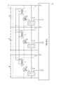
本発明の第1の態様は、直列に接続された複数の蓄電セルの各蓄電セルに一対一で対応する複数の電圧補正回路と、前記複数の蓄電セルの各蓄電セルの電圧に基づいて前記複数の電圧補正回路を制御する制御回路と、を備え、前記複数の電圧補正回路の各電圧補正回路は、対応する蓄電セルに並列に接続される第1コイルと、その蓄電セルに対する前記第1コイルの接続を前記制御回路の制御によってON/OFFするスイッチと、前記第1コイルと磁気的に結合する第2コイルと、を含み、前記複数の電圧補正回路は、各電圧補正回路の前記第2コイルが並列に接続されている、電圧バランス補正回路である。
本発明の第2の態様は、前述した本発明の第1の態様において、前記制御回路は、前記複数の電圧補正回路のうち、前記複数の蓄電セルの最も電圧が高い蓄電セルに対応する電圧補正回路のスイッチのON/OFFを繰り返し、その間、他の蓄電セルに対応する電圧補正回路のスイッチを整流状態で維持する、電圧バランス補正回路である。
本発明の第2の態様によれば、複数の蓄電セルの最も電圧が高い蓄電セルが放電して電圧が低下し、他の蓄電セルが充電されて電圧が上昇するので、短時間で効率的に複数の蓄電セルの電圧差を小さくすることができる。それによって短時間で効率的に複数の蓄電セルの各蓄電セルの電圧を均等にすることができる。
本発明の第3の態様は、前述した本発明の第2の態様において、前記制御回路は、前記電圧補正回路のスイッチを整流状態で維持する蓄電セルを各蓄電セルの電圧に応じて選択する、電圧バランス補正回路である。
本発明の第3の態様によれば、複数の蓄電セルの各蓄電セルの電圧を均等にする上で、蓄電セルの無駄な充放電を低減することができるので、さらに短時間で効率的に複数の蓄電セルの各蓄電セルの電圧を均等にすることができる。
本発明の第4の態様は、前述した本発明の第1〜第3の態様のいずれかにおいて、前記複数の電圧補正回路の各電圧補正回路は、対応する蓄電セルの電力で動作して前記スイッチをON/OFFするスイッチ駆動回路を含む、電圧バランス補正回路である。
本発明の第4の態様によれば、対応する蓄電セルの電力で動作してスイッチをON/OFFするスイッチ駆動回路が各電圧補正回路に設けられているため、スイッチをON/OFFさせるために外部電源装置等を設ける必要がないので、電圧バランス補正回路の小型化及び省電力化が可能になる。
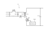
本発明の第5の態様は、前述した本発明の第1〜第4の態様のいずれかにおいて、前記電圧補正回路は、前記第1コイルが一次巻線、前記第2コイルが二次巻線として構成されるフォワード方式の絶縁型コンバータ回路である、電圧バランス補正回路である。
本発明の第5の態様によれば、第1コイル(一次巻線)と第2コイル(二次巻線)の電流が流れるタイミングが同じであるため、制御回路による各スイッチのON/OFF制御タイミングの設定が容易になるので、より高精度に複数の蓄電セルの各蓄電セルの電圧を均等にすることができる。
尚、本発明は、以下説明する実施例に特に限定されるものではなく、特許請求の範囲に記載された発明の範囲内で種々の変形が可能であることは言うまでもない。
多直列の高電圧蓄電ユニットは、制御回路10、蓄電モジュール20、n個の電圧補正回路11〜1nを備える。「複数の蓄電セル」としての蓄電モジュール20は、直列に接続されたn個の蓄電セルB1〜Bnを含む。蓄電セルB1〜Bnは、例えばニッケル水素二次電池、リチウムイオン二次電池、キャパシタ等の充放電可能な二次電池乃至蓄電素子である。
尚、例えば蓄電セルB1〜Bnとしてニッケル水素二次電池を用いる場合には、さらに蓄電セルB1〜Bnのそれぞれに温度センサ(図示せず)を設け、その温度センサの出力信号を制御回路10に入力して、蓄電セルB1〜Bnのそれぞれの温度を制御回路10で検出する構成とするのが好ましい。
電圧補正回路11〜1nは、図2に図示したように、例えばフォワード方式の絶縁型コンバータ回路を用いた構成とすることができる。以下、図2に図示した電圧補正回路11を参照しながら説明する。
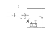
電圧補正回路11〜1nは、図4に図示したように、例えばフライバック方式の絶縁型コンバータ回路を用いた構成とすることができる。以下、図4に図示した電圧補正回路11を参照しながら説明する。
11〜1n 電圧補正回路
20 蓄電モジュール
B1〜Bn 蓄電セル
DR1〜DRn ドライバ
L11〜L1n 第1コイル
L21〜L2n 第2コイル
M1〜Mn コア
Q1〜Qn 電界効果トランジスタ
Claims (5)
- 直列に接続された複数の蓄電セルの各蓄電セルに一対一で対応する複数の電圧補正回路と、
前記複数の蓄電セルの各蓄電セルの電圧に基づいて前記複数の電圧補正回路を制御する制御回路と、を備え、
前記複数の電圧補正回路の各電圧補正回路は、対応する蓄電セルに並列に接続される第1コイルと、その蓄電セルに対する前記第1コイルの接続を前記制御回路の制御によってON/OFFするスイッチと、前記第1コイルと磁気的に結合する第2コイルと、を含み、
前記複数の電圧補正回路は、各電圧補正回路の前記第2コイルが並列に接続されている、電圧バランス補正回路。 - 請求項1に記載の電圧バランス補正回路において、前記制御回路は、前記複数の電圧補正回路のうち、前記複数の蓄電セルの最も電圧が高い蓄電セルに対応する電圧補正回路のスイッチのON/OFFを繰り返し、その間、他の蓄電セルに対応する電圧補正回路のスイッチを整流状態で維持する、電圧バランス補正回路。
- 請求項2に記載の電圧バランス補正回路において、前記制御回路は、前記電圧補正回路のスイッチを整流状態で維持する蓄電セルを各蓄電セルの電圧に応じて選択する、電圧バランス補正回路。
- 請求項1〜3のいずれか1項に記載の電圧バランス補正回路において、前記複数の電圧補正回路の各電圧補正回路は、対応する蓄電セルの電力で動作して前記スイッチをON/OFFするスイッチ駆動回路を含む、電圧バランス補正回路。
- 請求項1〜4のいずれか1項に記載の電圧バランス補正回路において、前記電圧補正回路は、前記第1コイルが一次巻線、前記第2コイルが二次巻線として構成されるフォワード方式又はフライバック方式の絶縁型コンバータ回路である、電圧バランス補正回路。
Priority Applications (6)
| Application Number | Priority Date | Filing Date | Title |
|---|---|---|---|
| JP2015068851A JP6509005B2 (ja) | 2015-03-30 | 2015-03-30 | 電圧バランス補正回路 |
| CN201680027932.2A CN107710544A (zh) | 2015-03-30 | 2016-02-12 | 电压平衡校正电路 |
| KR1020177030772A KR101975139B1 (ko) | 2015-03-30 | 2016-02-12 | 전압 밸런스 보정 회로 |
| DE112016001556.9T DE112016001556T5 (de) | 2015-03-30 | 2016-02-12 | Spannungsausgleichs-Korrekturschaltung |
| PCT/JP2016/054156 WO2016158031A1 (ja) | 2015-03-30 | 2016-02-12 | 電圧バランス補正回路 |
| US15/717,860 US11095128B2 (en) | 2015-03-30 | 2017-09-27 | Voltage balance correction circuit |
Applications Claiming Priority (1)
| Application Number | Priority Date | Filing Date | Title |
|---|---|---|---|
| JP2015068851A JP6509005B2 (ja) | 2015-03-30 | 2015-03-30 | 電圧バランス補正回路 |
Publications (2)
| Publication Number | Publication Date |
|---|---|
| JP2016189665A true JP2016189665A (ja) | 2016-11-04 |
| JP6509005B2 JP6509005B2 (ja) | 2019-05-08 |
Family
ID=57005660
Family Applications (1)
| Application Number | Title | Priority Date | Filing Date |
|---|---|---|---|
| JP2015068851A Active JP6509005B2 (ja) | 2015-03-30 | 2015-03-30 | 電圧バランス補正回路 |
Country Status (6)
| Country | Link |
|---|---|
| US (1) | US11095128B2 (ja) |
| JP (1) | JP6509005B2 (ja) |
| KR (1) | KR101975139B1 (ja) |
| CN (1) | CN107710544A (ja) |
| DE (1) | DE112016001556T5 (ja) |
| WO (1) | WO2016158031A1 (ja) |
Families Citing this family (2)
| Publication number | Priority date | Publication date | Assignee | Title |
|---|---|---|---|---|
| US11322947B2 (en) | 2017-10-04 | 2022-05-03 | Gs Yuasa International Ltd. | Energy storage apparatus |
| JP7781804B2 (ja) | 2023-03-02 | 2025-12-08 | 株式会社東芝 | 電力変換装置 |
Citations (6)
| Publication number | Priority date | Publication date | Assignee | Title |
|---|---|---|---|---|
| JP2005192281A (ja) * | 2003-12-24 | 2005-07-14 | Mitsubishi Electric Corp | バッテリ装置の過電圧保護回路 |
| JP2009540793A (ja) * | 2006-06-15 | 2009-11-19 | エスケー エナジー 株式会社 | 多重変圧器の2次巻線を並列に接続した電荷均等化装置 |
| JP2011200095A (ja) * | 2010-02-26 | 2011-10-06 | Sanyo Electric Co Ltd | 電池システム |
| JP2013055800A (ja) * | 2011-09-05 | 2013-03-21 | Toyota Industries Corp | 電池監視協調充電システム及び電動車両 |
| JP2014204638A (ja) * | 2013-04-09 | 2014-10-27 | Evtd株式会社 | バランス補正装置および蓄電システム |
| JPWO2013140710A1 (ja) * | 2012-03-19 | 2015-08-03 | Evtd株式会社 | バランス補正装置及び蓄電システム |
Family Cites Families (11)
| Publication number | Priority date | Publication date | Assignee | Title |
|---|---|---|---|---|
| US6115277A (en) * | 1999-01-07 | 2000-09-05 | The United States Of America As Represented By The Secretary Of The Army | Battery charger adapter for military vehicles |
| TW492021B (en) * | 1999-11-05 | 2002-06-21 | Tokin Corp | Electrical energy storage provided with cell energy adjusting device and adjust method of cell energy |
| US6150795A (en) * | 1999-11-05 | 2000-11-21 | Power Designers, Llc | Modular battery charge equalizers and method of control |
| US6583602B2 (en) * | 2001-05-11 | 2003-06-24 | Denso Corporation | Vehicular power supply apparatus and method of controlling the same |
| JP2003102132A (ja) * | 2001-09-25 | 2003-04-04 | Nisshinbo Ind Inc | 蓄電電源装置及びその充電制御方法 |
| JP5039335B2 (ja) | 2006-07-31 | 2012-10-03 | Fdk株式会社 | 多直列蓄電セル |
| US8692515B2 (en) * | 2006-06-22 | 2014-04-08 | Fdk Corporation | Series-connected rechargeable cells, series-connected rechargeable cell device, voltage-balance correcting circuit for series-connected cells |
| JP5046570B2 (ja) | 2006-06-22 | 2012-10-10 | Fdk株式会社 | 直列セルの電圧バランス回路 |
| KR101107999B1 (ko) * | 2007-10-16 | 2012-01-25 | 한국과학기술원 | 전압 센서와 전하 균일 장치가 결합된 배터리 운용 시스템 |
| US8493028B2 (en) * | 2009-04-03 | 2013-07-23 | Marvell World Trade Ltd. | Power management circuit for rechargeable battery stack |
| JP6170816B2 (ja) * | 2013-11-18 | 2017-07-26 | Fdk株式会社 | バランス補正装置及び蓄電装置 |
-
2015
- 2015-03-30 JP JP2015068851A patent/JP6509005B2/ja active Active
-
2016
- 2016-02-12 CN CN201680027932.2A patent/CN107710544A/zh active Pending
- 2016-02-12 KR KR1020177030772A patent/KR101975139B1/ko active Active
- 2016-02-12 DE DE112016001556.9T patent/DE112016001556T5/de active Pending
- 2016-02-12 WO PCT/JP2016/054156 patent/WO2016158031A1/ja not_active Ceased
-
2017
- 2017-09-27 US US15/717,860 patent/US11095128B2/en active Active
Patent Citations (6)
| Publication number | Priority date | Publication date | Assignee | Title |
|---|---|---|---|---|
| JP2005192281A (ja) * | 2003-12-24 | 2005-07-14 | Mitsubishi Electric Corp | バッテリ装置の過電圧保護回路 |
| JP2009540793A (ja) * | 2006-06-15 | 2009-11-19 | エスケー エナジー 株式会社 | 多重変圧器の2次巻線を並列に接続した電荷均等化装置 |
| JP2011200095A (ja) * | 2010-02-26 | 2011-10-06 | Sanyo Electric Co Ltd | 電池システム |
| JP2013055800A (ja) * | 2011-09-05 | 2013-03-21 | Toyota Industries Corp | 電池監視協調充電システム及び電動車両 |
| JPWO2013140710A1 (ja) * | 2012-03-19 | 2015-08-03 | Evtd株式会社 | バランス補正装置及び蓄電システム |
| JP2014204638A (ja) * | 2013-04-09 | 2014-10-27 | Evtd株式会社 | バランス補正装置および蓄電システム |
Also Published As
| Publication number | Publication date |
|---|---|
| JP6509005B2 (ja) | 2019-05-08 |
| US11095128B2 (en) | 2021-08-17 |
| DE112016001556T5 (de) | 2017-12-28 |
| KR101975139B1 (ko) | 2019-05-03 |
| CN107710544A (zh) | 2018-02-16 |
| US20180019600A1 (en) | 2018-01-18 |
| KR20170130577A (ko) | 2017-11-28 |
| WO2016158031A1 (ja) | 2016-10-06 |
Similar Documents
| Publication | Publication Date | Title |
|---|---|---|
| US9048669B2 (en) | Charge equalization apparatus and method for series-connected battery string | |
| CN101467324B (zh) | 多个变压器的次级线圈并联的电荷均衡设备 | |
| CN101467326B (zh) | 多个变压器的初级线圈并联的电荷均衡设备 | |
| CN101467328B (zh) | 电荷均衡设备 | |
| CN101606300B (zh) | 均衡充电设备 | |
| JP5171846B2 (ja) | 電荷均等化装置 | |
| US9368977B2 (en) | Battery equalization circuits for series charging/discharging and controlling methods thereof | |
| US9525356B2 (en) | Electric power conversion system | |
| US20120194137A1 (en) | Voltage equalizer for battery assembly | |
| CN113794373B (zh) | 多电平直流转换器及供电系统 | |
| JP6509005B2 (ja) | 電圧バランス補正回路 | |
| WO2013114757A1 (ja) | 電池均等化装置および方法 | |
| JP2015119614A (ja) | 蓄電状態調整回路、蓄電状態調整装置及び電池パック | |
| JP6994428B2 (ja) | 蓄電池充電装置 | |
| JP2016154423A (ja) | 電圧バランス装置 | |
| JP2011147300A (ja) | 電力逆変換装置及び電力逆変換方法 | |
| KR101816823B1 (ko) | 배터리 전하 균일 회로 | |
| WO2024106323A1 (ja) | 電源装置 | |
| CN121986442A (en) | Circuit arrangement for generating a DC output voltage and use of the circuit arrangement for testing an electrical energy store | |
| JP2020145771A (ja) | 充放電制御装置および充放電制御装置付き蓄電池 |
Legal Events
| Date | Code | Title | Description |
|---|---|---|---|
| RD04 | Notification of resignation of power of attorney |
Free format text: JAPANESE INTERMEDIATE CODE: A7424 Effective date: 20170511 |
|
| A621 | Written request for application examination |
Free format text: JAPANESE INTERMEDIATE CODE: A621 Effective date: 20180213 |
|
| A131 | Notification of reasons for refusal |
Free format text: JAPANESE INTERMEDIATE CODE: A131 Effective date: 20180725 |
|
| A521 | Request for written amendment filed |
Free format text: JAPANESE INTERMEDIATE CODE: A523 Effective date: 20180920 |
|
| A131 | Notification of reasons for refusal |
Free format text: JAPANESE INTERMEDIATE CODE: A131 Effective date: 20181219 |
|
| A521 | Request for written amendment filed |
Free format text: JAPANESE INTERMEDIATE CODE: A523 Effective date: 20190215 |
|
| TRDD | Decision of grant or rejection written | ||
| A01 | Written decision to grant a patent or to grant a registration (utility model) |
Free format text: JAPANESE INTERMEDIATE CODE: A01 Effective date: 20190327 |
|
| A61 | First payment of annual fees (during grant procedure) |
Free format text: JAPANESE INTERMEDIATE CODE: A61 Effective date: 20190402 |
|
| R150 | Certificate of patent or registration of utility model |
Ref document number: 6509005 Country of ref document: JP Free format text: JAPANESE INTERMEDIATE CODE: R150 |
|
| R250 | Receipt of annual fees |
Free format text: JAPANESE INTERMEDIATE CODE: R250 |
|
| R250 | Receipt of annual fees |
Free format text: JAPANESE INTERMEDIATE CODE: R250 |
|
| R250 | Receipt of annual fees |
Free format text: JAPANESE INTERMEDIATE CODE: R250 |
|
| R250 | Receipt of annual fees |
Free format text: JAPANESE INTERMEDIATE CODE: R250 |
|
| R250 | Receipt of annual fees |
Free format text: JAPANESE INTERMEDIATE CODE: R250 |