JP2016014635A - Automatic analyzer - Google Patents
Automatic analyzer Download PDFInfo
- Publication number
- JP2016014635A JP2016014635A JP2014137961A JP2014137961A JP2016014635A JP 2016014635 A JP2016014635 A JP 2016014635A JP 2014137961 A JP2014137961 A JP 2014137961A JP 2014137961 A JP2014137961 A JP 2014137961A JP 2016014635 A JP2016014635 A JP 2016014635A
- Authority
- JP
- Japan
- Prior art keywords
- reagent
- unit
- sample
- automatic analyzer
- probe
- Prior art date
- Legal status (The legal status is an assumption and is not a legal conclusion. Google has not performed a legal analysis and makes no representation as to the accuracy of the status listed.)
- Granted
Links
Images


Landscapes
- Automatic Analysis And Handling Materials Therefor (AREA)
Abstract
Description
本発明の実施形態は、被検体から採取されたサンプル等の液体に含まれる成分を分析する自動分析装置に関する。 Embodiments described herein relate generally to an automatic analyzer that analyzes components contained in a liquid such as a sample collected from a subject.
自動分析装置は、生化学検査項目や免疫検査項目等を対象とし、被検体から採取された被検サンプルと各検査項目の分析に用いる試薬との混合液の反応によって生ずる色調や濁りの変化を光学的に測定する。この測定により、被検サンプル中の様々な検査項目成分の濃度や酵素の活性等で表される分析データを生成する。 The automatic analyzer is intended for biochemical test items, immunological test items, etc., and changes in color tone and turbidity caused by the reaction of the mixture of the test sample collected from the sample and the reagent used for analysis of each test item. Measure optically. By this measurement, analysis data represented by the concentration of various test item components in the test sample, the activity of the enzyme, and the like are generated.
自動分析装置は、反応容器、サンプル分注プローブ、試薬分注プローブ、測定部及び洗浄ユニット等の各ユニットを備えている。反応容器は、一定のサイクルタイム毎に移動して停止する。サンプル分注プローブは、検査項目毎にサンプル容器21からサンプルを吸入して反応容器内へ吐出する。試薬分注プローブは、各検査項目分析用の試薬を試薬容器から吸入して反応容器内へ吐出する。測定部は、反応容器内に吐出されたサンプルと試薬との混合液を測定する。洗浄ユニットは、測定終了後の混合液を収容する反応容器内を洗浄する。
The automatic analyzer includes each unit such as a reaction container, a sample dispensing probe, a reagent dispensing probe, a measurement unit, and a washing unit. The reaction vessel moves and stops at every fixed cycle time. The sample dispensing probe sucks a sample from the
ところで、自動分析装置のうち、例えば反応容器が1のラインであり、複数の分析項目のうちいくつかを任意に選択できる、所謂シングルマルチランダムアクセスの自動分析装置がある。当該装置では、同一の試薬プローブを使用したために起こりうるキャリーオーバ、及びそれに起因する試薬干渉(試薬間干渉、クロスコンタミネーションも同義)が往々にして問題となる。 By the way, among automatic analyzers, for example, there is a so-called single multi-random access automatic analyzer in which a reaction vessel is one line and some of a plurality of analysis items can be arbitrarily selected. In the apparatus, carryover that may occur due to the use of the same reagent probe, and reagent interference caused by the same (interference between reagents and cross-contamination are also synonymous) often become problems.
目的は、キャリーオーバに起因する試薬干渉を回避または低減させる機能を有する自動分析装置を提供することにある。 An object of the present invention is to provide an automatic analyzer having a function of avoiding or reducing reagent interference caused by carryover.
上記目的を達成するために、実施形態に係る自動分析装置は、複数の試薬を各々格納する少なくとも一つの試薬庫と、前記少なくとも一つの試薬庫各々に対して複数ずつ対応づけられた複数の流路と、前記少なくとも一つの試薬庫各々における前記複数の試薬間での試薬干渉に関する情報を記憶する記憶ユニットと、前記試薬干渉に関する情報に基づいて、少なくとも干渉する複数の試薬については前記複数の流路のうち互いに異なる流路を割り当て、当該割り当てられた各流路を用いて前記干渉する複数の試薬を分注する制御部と、を具備する。 In order to achieve the above object, an automatic analyzer according to an embodiment includes at least one reagent store for storing a plurality of reagents, and a plurality of streams associated with each of the at least one reagent store. A path, a storage unit for storing information about reagent interference between the plurality of reagents in each of the at least one reagent storage, and at least a plurality of reagents that interfere with each other based on the information about the reagent interference. A controller that assigns different flow paths to each other and dispenses the plurality of interfering reagents using the assigned flow paths.
以下、図面を参照しながら実施形態を説明する。一例として、各実施形態は反応容器が1のラインであるシングルマルチランダムアクセスの自動分析装置とする。また試薬干渉は一般的な2の試薬間の干渉を扱う。しかしながら、これに限らず3以上の試薬間の干渉等も考えられる。 Hereinafter, embodiments will be described with reference to the drawings. As an example, each embodiment is a single multi-random access automatic analyzer with one reaction vessel. Reagent interference deals with general interference between two reagents. However, the present invention is not limited to this, and interference between three or more reagents is also conceivable.
(第1の実施形態)
第1の実施形態について説明する。
(First embodiment)
A first embodiment will be described.
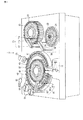
図1は、第1の実施形態に係る自動分析装置1の構成の一例を示す外観図である。同図に示すように、自動分析装置1は、サンプルディスク20(試薬庫)、サンプル分注ユニット30、反応容器を配置するための反応庫40、第1試薬庫50、第2試薬庫60、第1試薬分注ユニット70、第2試薬分注ユニット80、洗浄ユニット90、撹拌ユニット91、電解質測定ユニット92、測光ユニット11を具備する。サンプル分注ユニット30、第1試薬分注ユニット70、第2試薬分注ユニット80は、単に「分注ユニット」と呼ばれることもある。このような分注ユニット、あるいはサンプルディスク20等といった移動ユニットは、移動機構からの移動制御、位置決め制御に従って可動範囲内に原点となる位置(原点位置)と処理位置との間を移動しながら、所定の処理を実行する。また、本自動分析装置1は、個々の反応容器を個別に移動させるための移動機構を具備している。各構成要素について詳しく説明する。
FIG. 1 is an external view showing an example of the configuration of the
サンプルディスク20は、反応庫40の近傍に配置されている。サンプルディスク20は、サンプルが収容されたサンプル容器21を保持する。サンプルディスク20は、特定のサンプル容器21が所定のサンプル吸入位置に位置決められるように回動する。
The
サンプル分注ユニット30は、サンプルプローブ31とサンプルアーム32とを有し、反応庫40とサンプルディスク20との間に配置される。サンプル分注ユニット30は、サンプルプローブ31を、サンプルディスク20上のサンプル吸入位置に移動させる。そして、サンプルプローブ31は、サンプル吸入位置に配置されたサンプル容器21内へ下降し、液面を検知すると、さらに所定量だけ下降してサンプル容器21内のサンプルを所定量だけ吸入する。サンプルプローブ31は、サンプルを吸入し終わると上昇する。サンプルプローブ31が上昇し終わると、サンプルアーム32は回動して、サンプルプローブ31を、反応庫40のサンプル吐出位置へ移動させる。その後、サンプルプローブ31は、サンプル吐出位置に配置された反応容器に、吸入したサンプルを所定量だけ吐出する。サンプルは、測定対象項目毎に反応容器へ分注される。
The sample dispensing unit 30 includes a
反応庫40は、複数の反応容器をセルホルダ43に保持したまま所定の方向に沿って配列し、分析処理のシーケンスに従って、当該所定の方向に沿って複数の反応容器を搬送する。本実施形態においては、説明を具体的にするため、複数の反応容器が配列される方向(すなわち、複数の反応容器が搬送される方向)を、「配列方向」あるいは「搬送方向」と呼ぶ。また、反応庫40は、複数の反応容器41を保持しながら円周上に配列し、搬送するディスク状の反応庫40である場合とする。あくまでも説明のためであり、実際にはこの限りでない。係る反応庫40は、ある一定のサイクル(例えば90度)で回動と停止とを繰り返すことで、各反応容器41を各処理に対応するユニットの処置位置に搬送する。
The
第1試薬庫50は、反応庫40の近傍に配置される。第1試薬庫50は、各測定項目に対応する試薬が収容された複数の第1試薬容器51を保持する。第1試薬庫50は、特定の第1試薬容器51が所定の第1試薬吸入位置に位置決めされるように回動する。
The
第2試薬庫60は、反応庫40の内側に配置される。第2試薬庫60は、各測定項目に対応する試薬が収容された複数の第2試薬容器61を保持する。第2試薬庫60は、特定の第2試薬容器61が所定の第2試薬吸入位置に位置決めされるように回動する。
The
第1試薬分注ユニット70は、隣接した二つの第1プローブ71a及び71bと第1アーム72とを有し、反応庫40の外周近傍に配置される。第1試薬分注ユニット70の先端には隣接した二つの第1プローブ71a及び71bが取り付けられている。第1試薬分注ユニット70は、隣接した二つの第1プローブ71a及び71bを上下動及び回動可能に保持し、第1試薬庫50における所定試薬の吸入及び反応容器41への当該所定試薬の吐出を行う。なお、第1試薬分注ユニット70は、隣接した二つの第1プローブ71a及び71bをそれぞれ独立に上下動させ、両プローブ間に段差を設けることができる。
The first
第2試薬分注ユニット80は、隣接した二つの第1プローブ81a及び81bと第2アーム82を有し、反応庫40の外周近傍に配置される。第2試薬分注ユニット80の先端には隣接した二つの第1プローブ81a及び81bが取り付けられている。第2試薬分注ユニット80は、隣接した二つの第2プローブ81a及び81bを上下動及び回動可能に保持し、第2試薬庫60における所定試薬の吸入及び反応容器41への当該所定試薬の吐出を行う。なお、第2試薬分注ユニット80は、隣接した二つの第2プローブ81a及び81bをそれぞれ独立に上下動させ、両プローブ間に段差を設けることができる。
The second reagent dispensing unit 80 has two adjacent
洗浄ユニット90は、反応庫40の外周近傍に配置される。洗浄ユニット90には、複数本の洗浄ノズルと、乾燥ノズルが取り付けられている。洗浄ユニット90は、反応庫40の洗浄位置にある反応容器41を洗浄ノズルで洗浄し、乾燥ノズルを用いて乾燥する。なお、反応庫40に設けられる少なくとも一つの反応容器41は、必要に応じて、分注プローブを洗浄するための洗浄プールとして用いられる。しかしながら、当該構成に限定する趣旨ではなく、専用の洗浄プールを別途設けてもよい。
The
撹拌ユニット91は、反応庫40の外周近傍に配置される。撹拌ユニット91の先端には撹拌子が取り付けられている。撹拌子は、反応庫40上の撹拌位置に配置された反応容器41内のサンプルと試薬とを撹拌する。サンプルと試薬とが撹拌されることにより、サンプルと試薬との化学反応が促進する。
The stirring
電解質測定ユニット92は、反応容器41内のサンプルと試薬の混合液中に存在する特定電解質の測定を行なう。
The
測光ユニット11は、反応庫40の下側に設けられ、反応容器41内のサンプルと試薬との混合液の吸光度を測定する。測光ユニット11は、図示されていない光源部、照射光学部、検出光学部、分光部、光検出部を有する。光源部から照射される測定用の光は、照射光学部によって測光焦点Fにおいて集光される。反応容器41は、測光焦点Fあるいはその近傍を横切るように反応庫40により回動される。反応容器41内のサンプルを透過した光は、検出光学部を通過した後、分光部において分光され、光検出部において光から電気信号に変換され、後述の分析部6に送り出される。
The
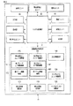
図2は、本実施形態に係る自動分析装置1の構成機能を示すブロック図である。図2を参照しながら、自動分析装置1の動作制御について説明する。ただし、図1と重複するものに関しては、説明を省略する。
FIG. 2 is a block diagram showing the configuration functions of the
自動分析装置1は、システム制御部2、記憶ユニット3、入力部4、表示部5、分析部6、吸入吐出ユニット7、測光ユニット11、洗浄ユニット90、撹拌ユニット91、電解質測定ユニット92、及び各種機械系駆動部を具備する。各種機械系駆動部は、サンプルディスク駆動部120、サンプル分注ユニット駆動部130、反応庫駆動部140、第1試薬庫駆動部150、第2試薬庫駆動部160、第1試薬分注ユニット駆動部170、第2試薬分注ユニット駆動部180の総称である。
The
システム制御部2は、本自動分析装置1の動作に関する総括的な制御を行う。記憶ユニット3は、本自動分析装置1の動作プログラム、分析処理のための各種情報、試薬干渉に関する情報(詳細は後述)、分析結果、設定された測定項目、測定に用いる試薬、試薬残量等を記憶する。
The
記憶ユニット3は、特定の位置に設定された反応容器41の測光位置(あるいは、反応容器41毎の測光位置)、特定の位置に設定された反応容器41の反応時間(あるいは、反応容器41毎の反応時間)を記憶する。
The
入力部4は、キーボード、マウス等の入力手段を備える。
The
表示部5は、検体情報、測定項目の選択画面、分析結果等を表示する。
The
分析部6は、測光ユニット11より得られた測光結果等に基づいて、各検体に関する各サンプルの成分を分析する。
The
吸入吐出ユニット7は、流路と接続され、サンプルや試薬の吸引吐出を行う。
The suction /
各種機械系駆動部は、システム制御部2からの制御に従って、所定のタイミングで対応する機械系を駆動させる。特に、第1試薬分注ユニット駆動部170は、隣接した二つの第1プローブ71a及び71b間に段差を設けるための第1プローブ上下駆動機構171と、第1アーム駆動機構172とを具備する。同様に、第2試薬分注ユニット駆動部180は、同目的の第2プローブ上下駆動機構181と、第2アーム駆動機構182とを具備する。
The various mechanical system drive units drive the corresponding mechanical system at a predetermined timing according to the control from the
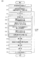
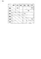
図3は、第1の実施形態に係る自動分析装置1において、分注に関する一連の動作の流れを説明するためのフローチャートである。また、図4は試薬干渉に関する情報をまとめたテーブルの一例(第1試薬)を示す図である。
FIG. 3 is a flowchart for explaining a flow of a series of operations related to dispensing in the
(ステップ1)操作者は、複数の分析項目の中から所望の分析項目を入力部4より入力する。また、操作者による動作開始のトリガにより、動作が開始される。当該トリガはボタンやレバー等機械的なトリガでもよいし、入力部4におけるマウスによるクリック動作等電子的なトリガでもよい。
(Step 1) The operator inputs a desired analysis item from the plurality of analysis items through the
(ステップ2)システム制御部2は、ステップ1にて入力された所望の分析項目と、記憶ユニット3に記憶されている当該試薬干渉に関する情報とに基づいて、試薬干渉を極力回避可能に、各試薬に対応する使用するプローブ(流路)を決定する。
(Step 2) Based on the desired analysis item input in
ここで、試薬干渉に関する情報について、第1試薬を例にとり説明をする。また、第2試薬についても、下記説明の通りである。 Here, the information regarding reagent interference will be described using the first reagent as an example. The second reagent is also as described below.
第1試薬庫50は、第1試薬に分類される複数種類の試薬を格納している。第1試薬のうちのいくつかの組み合わせは、試薬干渉(試薬間干渉、クロスコンタミネーションも略同義)を引き起こす。
The
記憶ユニット3は、図4に例示されるような、当該試薬干渉に関する情報を記憶している。本実施形態では、第1試薬に分類される試薬はA〜Fの6種類であると仮定する。図4に示される通り、試薬Aと試薬B、試薬Aと試薬F、試薬Bと試薬E、試薬Cと試薬D,及び試薬Eと試薬Fは、互いに試薬干渉を引き起こす。
The
以下説明するステップ3〜ステップ9を1回の分析項目に関するサイクルと呼ぶ。
(ステップ3)サンプル分注ユニット30は、所望のサンプルをサンプル容器21から吸入する。そしてサンプル分注ユニット30は、吸入したサンプルを所定量だけ所定の反応容器41へ吐出する。
(Step 3) The sample dispensing unit 30 sucks a desired sample from the
(ステップ4)本ステップは、第1試薬分注ユニット70の動作に関わる。4a〜4eの5段階のフェーズに分けて説明する。また、図4に例示した試薬Aを分注するものとする。
(Step 4) This step relates to the operation of the first
(4a)第1試薬分注ユニット駆動部170は、第1アーム駆動機構172を駆動させ、隣接する二つの第1プローブ71a及び71bを所望の第1試薬(試薬A)が格納されている第1試薬容器51近傍に移動する。
(4a) The first reagent dispensing
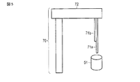
(4b)第1試薬分注ユニット駆動部170は、第1プローブ上下駆動機構171を駆動させ、ステップ2で決定された使用するプローブと使用しないプローブとに、上下方向の段差を設ける。図5にこの動作の様子を示す。同図は、第1プローブ71aを使用するプローブとし、第1プローブ71bと比して下方向へ位置させた様子を示している。あるいは第1プローブ71bを、第1プローブ71aと比して上方向へ位置させてもよい。なお、(4a)と(4b)との動作順序を入れ替えてもかまわない。
(4b) The first reagent dispensing
(4c)第1試薬分注ユニット駆動部170は、第1アーム駆動機構172を駆動させ、第1プローブ71aを試薬Aが格納されている第1試薬容器51の中に挿入する。さらに吸入吐出ユニットは、試薬Aを吸入する。
(4c) The first reagent dispensing
(4d)第1試薬分注ユニット駆動部170は、第1アーム駆動機構172を駆動させ、隣接する二つの第1プローブ71a及び71bを所望の反応容器41近傍に移動する。
(4d) The first reagent dispensing
(4e)吸入吐出ユニットは、吸入された試薬Aを、ステップ3において所定のサンプルが吐出された所定の反応容器41へ吐出する。
(4e) The suction / discharge unit discharges the sucked reagent A to the
(ステップ5)撹拌ユニット91は、反応容器41内のサンプルと第1試薬とを撹拌する。サンプルと第1試薬とが撹拌されることにより、サンプルと第1試薬との化学反応が促進する。
(Step 5) The stirring
(ステップ6)第2試薬分注ユニット80は、所望の第2試薬を第2試薬容器61から吸入する。そして第2試薬分注ユニット80は、吸入した第2試薬を所定量だけ、前述の所望のサンプルと所望の第1試薬とを吐出した反応容器41へ吐出する。詳細な動作については、ステップ4と略同様である。
(Step 6) The second reagent dispensing unit 80 sucks the desired second reagent from the
(ステップ7)撹拌ユニット91は、反応容器41内のサンプルと第1試薬と第2試薬とを撹拌する。サンプルと第1試薬と第2試薬とが撹拌されることにより、サンプルと第1試薬と第2試薬との化学反応が促進する。
(Step 7) The stirring
(ステップ8)測光ユニット11は、反応容器41内のサンプルと第1試薬と第2試薬との混合液の吸光度を測定する。また、分析部6は当該吸光度に基づいて、サンプルの成分分析を行う。
(Step 8) The
(ステップ9)洗浄ユニット90は、サンプルプローブ31と第1プローブ71a及び71bと第2プローブ81a及び81bとを洗浄する。なお前述の通り、本実施形態では、試薬干渉の回避、低減を行っているため、当該洗浄は原則洗浄剤を用いない水洗いでかまわない。
(Step 9) The
以上のステップ3〜ステップ9が、1回の分析項目に関するサイクルである。もし次の分析項目が存在する場合は、再度ステップ3から上記と略同一のステップをたどる。一方すべての分析項目が完了した場合、システム制御部2は一連の分析動作を終了する。
The
ここでは、次の分析項目が存在し、その際に分注する第1試薬を図4に例示した試薬Bとして、ステップ4について説明をする。それ以外のステップについては、前述のサイクルと略同様であるため、省略する。
Here, the following analysis items exist, and
(ステップ4)1回前の分析項目に関する前述のサイクルにおいて、第1試薬分注ユニット70は、第1試薬として試薬Aを分注した。しかし、図4に示されるように、先に分注された試薬Aとこれから分注する試薬Bとは、試薬干渉を引き起こす。
(Step 4) In the above-described cycle related to the previous analysis item, the first
(4a)第1試薬分注ユニット駆動部170は、第1アーム駆動機構172を駆動させ、隣接する二つの第1プローブ71a及び71bを所望の第1試薬(試薬B)が格納されている第1試薬容器51近傍に移動する。
(4a) The first reagent dispensing
(4b)1回前の分析項目に関する前述のサイクルにおいては、第1プローブ71aが使用された。したがって第1試薬分注ユニット駆動部170は、ステップ2で決定された使用するプローブとして第1プローブ71bを、第1プローブ71aと比して下方向へ位置させる。あるいは第1プローブ71aを、第1プローブ71bと比して上方向へ位置させてもよい。なお、(4a)と(4b)との動作順序を入れ替えてもかまわない。
(4b) In the above-described cycle related to the analysis item of the previous time, the
(4c)第1試薬分注ユニット駆動部170は、第1アーム駆動機構172を駆動させ、第1プローブ71bを試薬Bが格納されている第1試薬容器51の中に挿入する。さらに吸入吐出ユニットは、試薬Bを吸入する。
(4c) The first reagent dispensing
(4d)第1試薬分注ユニット駆動部170は、第1アーム駆動機構172を駆動させ、隣接する二つの第1プローブ71a及び71bを所望の反応容器41近傍に移動する。
(4d) The first reagent dispensing
(4e)吸入吐出ユニットは、吸入された試薬Bを、ステップ3において所定のサンプルが吐出された所定の反応容器41へ吐出する。
(4e) The inhalation / discharge unit discharges the inhaled reagent B to the
以上のように、複数のサイクルにおいて、同一の試薬分注ユニットに関連付けられた二つの試薬プローブを使い分けることで、本実施形態は試薬干渉を極力回避、低減する。 As described above, the present embodiment avoids and reduces reagent interference as much as possible by properly using two reagent probes associated with the same reagent dispensing unit in a plurality of cycles.
以下、本実施形態の変形例について述べる。 Hereinafter, modifications of the present embodiment will be described.
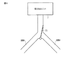
本実施形態に係る自動分析装置1は、各分注ユニットに対して、隣接する二つのプローブの流路それぞれに対応する二つの吸入吐出ユニット7を具備してもよいし、一つの吸入吐出ユニット7と、流路切替機構とを具備してもよい。図6は、後者の場合の一例を示す図である。ここでの流路切替機構は、電磁弁73とする。システム制御部2は、使用するプローブに対応するように、分注毎に吸入吐出ユニット7及び電磁弁73の制御を行う。
The
本実施形態に係る自動分析装置1は、各試薬と使用するプローブとを分注前にあらかじめ決定している。しかしながら代替として、所定の回次において分注された試薬の種類と、その次の回次において分注される予定の試薬の種類と、に基づいて、逐次使用するプローブを選択してもよい。
In the
また、使用するプローブと使用しないプローブとにおける段差(ステップ4,4b参照)を設けない場合について説明する。段差がない場合、分注時に使用しないプローブにも当該試薬が付着してしまう。しかしながら、試薬のキャリーオーバの大部分は、流路内部によるものである。したがって、段差を設けないことによる試薬干渉の影響は、流路内部によるものと比べ相対的に小さい。すなわち、製作費用等を考慮し、第1プローブ上下駆動機構171及び第2プローブ上下駆動機構181の少なくとも一方を具備しない変形例も挙げられる。
Further, a case will be described in which a step (see
さらに、本実施形態では、具備する試薬庫は二つとし、一つの試薬庫に対応するプローブ(流路)は二つとした。しかしながら、変形例として、試薬庫は三つ以上でもよいし、一つの試薬庫に対応するプローブ(流路)は三つ以上でもよい。 Furthermore, in this embodiment, two reagent containers are provided, and two probes (channels) corresponding to one reagent container are provided. However, as a modification, three or more reagent containers may be used, and three or more probes (channels) corresponding to one reagent container may be used.
以上に述べた第1の実施形態によれば、試薬干渉を極力回避しながら、サンプルの自動分析を行うことができる。その効果として、従来よりも正確な分析結果を取得できるだけでなく、プローブの洗浄に関して原則水洗いで済み、洗浄剤を使用する工程を省略できる。その結果、スループットの向上と、洗浄剤に伴う経費削減とが実現できる。 According to the first embodiment described above, automatic analysis of a sample can be performed while avoiding reagent interference as much as possible. As an effect, not only a more accurate analysis result can be obtained than in the prior art, but also the probe can be washed with water in principle, and the step of using a cleaning agent can be omitted. As a result, an improvement in throughput and a reduction in costs associated with the cleaning agent can be realized.
(第2の実施形態)
第2の実施形態について説明する。第1の実施形態と同一の構成要素には同一の符号を付し、重複説明は省略する。
(Second Embodiment)
A second embodiment will be described. The same components as those in the first embodiment are denoted by the same reference numerals, and redundant description is omitted.
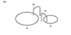
図7は、第2の実施形態に係る自動分析装置1において、試薬庫に対する分注ユニットの構成の一例を示す外観図である。同図を用いて、本実施形態におけるプローブ(流路)の選択を説明する。なお同図においては、第1試薬庫50及びそれに対する分注ユニットを取り上げているが、第2試薬庫60及びそれに対する分注ユニットも略同一の構造・機能を有する。
FIG. 7 is an external view showing an example of a configuration of a dispensing unit for the reagent storage in the
本実施形態に係る自動分析装置1は、一つの第1試薬庫50に対して、第1試薬分注ユニット70a及び第1試薬分注ユニット70bの二つを具備する。また、第1試薬分注ユニット70a及び第1試薬分注ユニット70bは各々一つのプローブを具備する。
The
当該独立のユニットに含まれる二つのプローブに対して、第1の実施形態同様、システム制御部2は、記憶ユニット3に記憶されている試薬干渉に関する情報を参照し、各試薬に対応する使用すべきプローブを決定する。図4に示された試薬を用いるならば、例えば試薬Aに対して第1試薬分注ユニット70aを、試薬Bに対して第1試薬分注ユニット70bをそれぞれ割り当てるなどとすれば、試薬干渉が回避される。
For the two probes included in the independent unit, as in the first embodiment, the
以上に述べた第2の実施形態によれば、試薬干渉を極力回避しながら、サンプルの自動分析を行うことができる。その効果として、従来よりも正確な分析結果を取得できるだけでなく、プローブの洗浄に関して原則水洗いで済み、洗浄剤を使用する工程を省略できる。その結果、スループットの向上と、洗浄剤に伴う経費削減とが実現できる。 According to the second embodiment described above, automatic analysis of a sample can be performed while avoiding reagent interference as much as possible. As an effect, not only a more accurate analysis result can be obtained than in the prior art, but also the probe can be washed with water in principle, and the step of using a cleaning agent can be omitted. As a result, an improvement in throughput and a reduction in costs associated with the cleaning agent can be realized.
(第3の実施形態)
第3の実施形態について説明する。第1及び第2の実施形態と同一の構成要素には同一の符号を付し、重複説明は省略する。
(Third embodiment)
A third embodiment will be described. The same components as those in the first and second embodiments are denoted by the same reference numerals, and redundant description is omitted.
図8は、第3の実施形態に係る自動分析装置1において、第1試薬分注ユニット70が有する第1プローブ71の外観図である。さらに図9は、図8に示された第1プローブ71のA−A’における断面図である。なお同図においては、第1試薬分注ユニット70が有する第1プローブ71を取り上げているが、第2試薬分注ユニット80も略同一の構造・機能を有する。図8に示される通り、第1試薬分注ユニット70は一つの第1プローブ71を具備する。また図9に示される通り、第1プローブ71は内部に二つの流路を具備する。第1プローブ71に含まれる二つの流路に対して、第1の実施形態及び第2の実施形態同様、システム制御部2は、記憶ユニット3に記憶されている試薬干渉に関する情報を参照し、試薬干渉を極力回避可能に、各試薬に対応する使用すべき流路を決定する。図4に示された試薬を用いるならば、例えば試薬Aに対して図9の流路Aを、試薬Bに対して図9の流路Bをそれぞれ割り当てるなどとすれば、試薬干渉が回避される。
FIG. 8 is an external view of the
なお、本実施形態では、一つのプローブに二つの流路を具備しているため、試薬の吸入時、使用しない流路の入り口周辺にも当該試薬が付着してしまう。しかしながら、試薬のキャリーオーバの大部分は、流路内部によるものである。よって、本実施形態における使用しない流路の入り口周辺でのキャリーオーバは、試薬干渉に大きくは影響しない。 In this embodiment, since one probe has two flow paths, the reagent adheres to the vicinity of the entrance of the unused flow path when the reagent is inhaled. However, the majority of reagent carryover is due to the interior of the flow path. Therefore, the carry-over around the entrance of the unused channel in this embodiment does not greatly affect the reagent interference.
以上に述べた第3の実施形態によれば、試薬干渉を極力回避しながら、サンプルの自動分析を行うことができる。その効果として、従来よりも正確な分析結果を取得できるだけでなく、プローブの洗浄に関して原則水洗いで済み、洗浄剤を使用する工程を省略できる。その結果、スループットの向上と、洗浄剤に伴う経費削減とが実現できる。 According to the third embodiment described above, the sample can be automatically analyzed while avoiding reagent interference as much as possible. As an effect, not only a more accurate analysis result can be obtained than in the prior art, but also the probe can be washed with water in principle, and the step of using a cleaning agent can be omitted. As a result, an improvement in throughput and a reduction in costs associated with the cleaning agent can be realized.
本発明のいくつかの実施形態を説明したが、これらの実施形態は、例として提示したものであり、発明の範囲を限定することは意図していない。これら新規な実施形態は、その他の様々な形態で実施されることが可能であり、発明の要旨を逸脱しない範囲で、種々の省略、置き換え、変更を行うことができる。これら実施形態やその変形は、発明の範囲や要旨に含まれるとともに、特許請求の範囲に記載された発明とその均等の範囲に含まれるものである。 Although several embodiments of the present invention have been described, these embodiments are presented by way of example and are not intended to limit the scope of the invention. These novel embodiments can be implemented in various other forms, and various omissions, replacements, and changes can be made without departing from the scope of the invention. These embodiments and modifications thereof are included in the scope and gist of the invention, and are included in the invention described in the claims and the equivalents thereof.
1…自動分析装置、2…システム制御部、3…記憶ユニット、4…入力部、5…表示部、6…分析部、7…吸入吐出ユニット、11…測光ユニット、20…サンプルディスク、21…サンプル容器、30…サンプル分注ユニット、31…サンプルプローブ、32…サンプルアーム、40…反応庫、41…反応容器、43…セルホルダ、50…第1試薬庫、51…第1試薬容器、60…第2試薬庫、61…第2試薬容器、70…第1試薬分注ユニット、71…第1プローブ、72…第1アーム、73…電磁弁、80…第2試薬分注ユニット、81…第2プローブ、82…第2アーム、90…洗浄ユニット、91…撹拌ユニット、92…電解質測定ユニット、120…サンプルディスク駆動部、130…サンプル分注ユニット駆動部、140…反応庫駆動部、150…第1試薬庫駆動部、160…第2試薬庫駆動部、170…第1試薬分注ユニット駆動部、171…第1プローブ上下駆動機構、172…第1アーム駆動機構、180…第2試薬分注ユニット駆動部、181…第2プローブ上下駆動機構、182…第2アーム駆動機構。
DESCRIPTION OF
Claims (7)
前記少なくとも一つの試薬庫各々に対して複数ずつ対応づけられた複数の流路と、
前記少なくとも一つの試薬庫各々における前記複数の試薬間での試薬干渉に関する情報を記憶する記憶ユニットと、
前記試薬干渉に関する情報に基づいて、少なくとも干渉する複数の試薬については前記複数の流路のうち互いに異なる流路を割り当て、当該割り当てられた各流路を用いて前記干渉する複数の試薬を分注する制御部と、
を具備することを特徴とする自動分析装置。 At least one reagent storage for storing a plurality of reagents each;
A plurality of flow paths associated with each of the at least one reagent storage;
A storage unit for storing information relating to reagent interference between the plurality of reagents in each of the at least one reagent storage;
Based on the information on the reagent interference, at least a plurality of interfering reagents are assigned different channels among the plurality of channels, and the interfering reagents are dispensed using the allocated channels. A control unit,
The automatic analyzer characterized by comprising.
前記制御部は、前記試薬干渉に関する情報に基づいて前記弁を制御することで、前記流路の割り当てを行うことを特徴とする請求項1乃至4のうちいずれか一項記載の自動分析装置。 Further comprising a flow path switching mechanism for selecting a flow path used for dispensing the reagent among the plurality of flow paths using a valve;
5. The automatic analyzer according to claim 1, wherein the controller assigns the flow path by controlling the valve based on information related to the reagent interference. 6.
Priority Applications (1)
| Application Number | Priority Date | Filing Date | Title |
|---|---|---|---|
| JP2014137961A JP6411098B2 (en) | 2014-07-03 | 2014-07-03 | Automatic analyzer |
Applications Claiming Priority (1)
| Application Number | Priority Date | Filing Date | Title |
|---|---|---|---|
| JP2014137961A JP6411098B2 (en) | 2014-07-03 | 2014-07-03 | Automatic analyzer |
Publications (2)
| Publication Number | Publication Date |
|---|---|
| JP2016014635A true JP2016014635A (en) | 2016-01-28 |
| JP6411098B2 JP6411098B2 (en) | 2018-10-24 |
Family
ID=55230928
Family Applications (1)
| Application Number | Title | Priority Date | Filing Date |
|---|---|---|---|
| JP2014137961A Active JP6411098B2 (en) | 2014-07-03 | 2014-07-03 | Automatic analyzer |
Country Status (1)
| Country | Link |
|---|---|
| JP (1) | JP6411098B2 (en) |
Citations (7)
| Publication number | Priority date | Publication date | Assignee | Title |
|---|---|---|---|---|
| JPS63200066A (en) * | 1987-02-16 | 1988-08-18 | Toshiba Corp | Automatic chemical analyzer |
| JPH04350562A (en) * | 1991-05-27 | 1992-12-04 | Olympus Optical Co Ltd | Automatic analyser |
| JPH06174603A (en) * | 1992-12-10 | 1994-06-24 | Olympus Optical Co Ltd | Dispensing device for automatic analyzer |
| JP2001305145A (en) * | 2000-04-20 | 2001-10-31 | Toshiba Medical System Co Ltd | Autoanalyzer |
| JP2009031174A (en) * | 2007-07-30 | 2009-02-12 | Hitachi High-Technologies Corp | Automatic analyzer |
| JP2009053028A (en) * | 2007-08-27 | 2009-03-12 | Olympus Corp | Automatic analyzer |
| EP2372371A2 (en) * | 2010-04-01 | 2011-10-05 | Kabushiki Kaisha Toshiba | Automatic Analyzer |
-
2014
- 2014-07-03 JP JP2014137961A patent/JP6411098B2/en active Active
Patent Citations (7)
| Publication number | Priority date | Publication date | Assignee | Title |
|---|---|---|---|---|
| JPS63200066A (en) * | 1987-02-16 | 1988-08-18 | Toshiba Corp | Automatic chemical analyzer |
| JPH04350562A (en) * | 1991-05-27 | 1992-12-04 | Olympus Optical Co Ltd | Automatic analyser |
| JPH06174603A (en) * | 1992-12-10 | 1994-06-24 | Olympus Optical Co Ltd | Dispensing device for automatic analyzer |
| JP2001305145A (en) * | 2000-04-20 | 2001-10-31 | Toshiba Medical System Co Ltd | Autoanalyzer |
| JP2009031174A (en) * | 2007-07-30 | 2009-02-12 | Hitachi High-Technologies Corp | Automatic analyzer |
| JP2009053028A (en) * | 2007-08-27 | 2009-03-12 | Olympus Corp | Automatic analyzer |
| EP2372371A2 (en) * | 2010-04-01 | 2011-10-05 | Kabushiki Kaisha Toshiba | Automatic Analyzer |
Also Published As
| Publication number | Publication date |
|---|---|
| JP6411098B2 (en) | 2018-10-24 |
Similar Documents
| Publication | Publication Date | Title |
|---|---|---|
| US8999267B2 (en) | Automatic analyzer | |
| JPWO2013058170A1 (en) | Automatic analyzer | |
| JP6312313B2 (en) | Automatic analyzer and automatic analysis method | |
| JP2009288052A (en) | Automatic analyzer | |
| JP2017032500A (en) | Automatic analyzer | |
| JP5134452B2 (en) | Automatic analyzer | |
| JP6758821B2 (en) | Automatic analyzer | |
| JP6214902B2 (en) | Automatic analyzer | |
| JP6411098B2 (en) | Automatic analyzer | |
| US20250110142A1 (en) | Automatic analyzer and automatic analysis method | |
| JP6058277B2 (en) | Automatic analyzer | |
| JP4408404B2 (en) | Automatic analyzer | |
| JP6656902B2 (en) | Automatic analyzer | |
| CN111164430A (en) | Automatic analyzer | |
| WO2021131296A1 (en) | Automatic analysis device and control program for automatic analysis device | |
| JP6071384B2 (en) | Automatic analyzer | |
| JP2016170075A (en) | Automatic analyzer and method for automatic analysis | |
| US20250076332A1 (en) | Automatic analyzing apparatus and method | |
| JP5808473B2 (en) | Automatic analyzer | |
| JP7237569B2 (en) | automatic analyzer | |
| JP6915010B2 (en) | Automatic analyzer and automatic analysis method | |
| JP6987533B2 (en) | Automatic analyzer | |
| JP2005201771A (en) | Automatic analyzer | |
| JP5706252B2 (en) | Automatic analyzer | |
| JP6976781B2 (en) | Automatic analyzer |
Legal Events
| Date | Code | Title | Description |
|---|---|---|---|
| A711 | Notification of change in applicant |
Free format text: JAPANESE INTERMEDIATE CODE: A711 Effective date: 20160512 |
|
| A621 | Written request for application examination |
Free format text: JAPANESE INTERMEDIATE CODE: A621 Effective date: 20170419 |
|
| A977 | Report on retrieval |
Free format text: JAPANESE INTERMEDIATE CODE: A971007 Effective date: 20180115 |
|
| A131 | Notification of reasons for refusal |
Free format text: JAPANESE INTERMEDIATE CODE: A131 Effective date: 20180227 |
|
| A521 | Request for written amendment filed |
Free format text: JAPANESE INTERMEDIATE CODE: A523 Effective date: 20180420 |
|
| TRDD | Decision of grant or rejection written | ||
| A01 | Written decision to grant a patent or to grant a registration (utility model) |
Free format text: JAPANESE INTERMEDIATE CODE: A01 Effective date: 20180828 |
|
| A61 | First payment of annual fees (during grant procedure) |
Free format text: JAPANESE INTERMEDIATE CODE: A61 Effective date: 20180926 |
|
| R150 | Certificate of patent or registration of utility model |
Ref document number: 6411098 Country of ref document: JP Free format text: JAPANESE INTERMEDIATE CODE: R150 |