JP2016005404A - Manufacturing method of laminated core - Google Patents
Manufacturing method of laminated core Download PDFInfo
- Publication number
- JP2016005404A JP2016005404A JP2014125546A JP2014125546A JP2016005404A JP 2016005404 A JP2016005404 A JP 2016005404A JP 2014125546 A JP2014125546 A JP 2014125546A JP 2014125546 A JP2014125546 A JP 2014125546A JP 2016005404 A JP2016005404 A JP 2016005404A
- Authority
- JP
- Japan
- Prior art keywords
- core
- bridge portion
- manufacturing
- laminated
- punched
- Prior art date
- Legal status (The legal status is an assumption and is not a legal conclusion. Google has not performed a legal analysis and makes no representation as to the accuracy of the status listed.)
- Granted
Links
- 238000004519 manufacturing process Methods 0.000 title claims abstract description 40
- 238000000034 method Methods 0.000 claims abstract description 28
- 238000003780 insertion Methods 0.000 claims abstract description 25
- 230000037431 insertion Effects 0.000 claims abstract description 25
- 239000000463 material Substances 0.000 claims abstract description 23
- 230000002093 peripheral effect Effects 0.000 claims abstract description 20
- 238000004080 punching Methods 0.000 claims abstract description 19
- XEEYBQQBJWHFJM-UHFFFAOYSA-N Iron Chemical group [Fe] XEEYBQQBJWHFJM-UHFFFAOYSA-N 0.000 claims description 45
- 238000010030 laminating Methods 0.000 claims description 5
- 230000015572 biosynthetic process Effects 0.000 description 7
- 229910052742 iron Inorganic materials 0.000 description 3
- 230000004907 flux Effects 0.000 description 2
- 238000003466 welding Methods 0.000 description 2
- 229910000976 Electrical steel Inorganic materials 0.000 description 1
- 239000000853 adhesive Substances 0.000 description 1
- 230000001070 adhesive effect Effects 0.000 description 1
- 238000005452 bending Methods 0.000 description 1
- 238000007796 conventional method Methods 0.000 description 1
- 150000002505 iron Chemical group 0.000 description 1
- 238000005304 joining Methods 0.000 description 1
- 238000003825 pressing Methods 0.000 description 1
- 230000000750 progressive effect Effects 0.000 description 1
- 239000013585 weight reducing agent Substances 0.000 description 1
Images
Classifications
-
- H—ELECTRICITY
- H02—GENERATION; CONVERSION OR DISTRIBUTION OF ELECTRIC POWER
- H02K—DYNAMO-ELECTRIC MACHINES
- H02K15/00—Methods or apparatus specially adapted for manufacturing, assembling, maintaining or repairing of dynamo-electric machines
- H02K15/02—Methods or apparatus specially adapted for manufacturing, assembling, maintaining or repairing of dynamo-electric machines of stator or rotor bodies
- H02K15/03—Methods or apparatus specially adapted for manufacturing, assembling, maintaining or repairing of dynamo-electric machines of stator or rotor bodies having permanent magnets
-
- H—ELECTRICITY
- H02—GENERATION; CONVERSION OR DISTRIBUTION OF ELECTRIC POWER
- H02K—DYNAMO-ELECTRIC MACHINES
- H02K15/00—Methods or apparatus specially adapted for manufacturing, assembling, maintaining or repairing of dynamo-electric machines
- H02K15/02—Methods or apparatus specially adapted for manufacturing, assembling, maintaining or repairing of dynamo-electric machines of stator or rotor bodies
-
- B—PERFORMING OPERATIONS; TRANSPORTING
- B21—MECHANICAL METAL-WORKING WITHOUT ESSENTIALLY REMOVING MATERIAL; PUNCHING METAL
- B21D—WORKING OR PROCESSING OF SHEET METAL OR METAL TUBES, RODS OR PROFILES WITHOUT ESSENTIALLY REMOVING MATERIAL; PUNCHING METAL
- B21D28/00—Shaping by press-cutting; Perforating
- B21D28/02—Punching blanks or articles with or without obtaining scrap; Notching
- B21D28/10—Incompletely punching in such a manner that the parts are still coherent with the work
-
- B—PERFORMING OPERATIONS; TRANSPORTING
- B21—MECHANICAL METAL-WORKING WITHOUT ESSENTIALLY REMOVING MATERIAL; PUNCHING METAL
- B21D—WORKING OR PROCESSING OF SHEET METAL OR METAL TUBES, RODS OR PROFILES WITHOUT ESSENTIALLY REMOVING MATERIAL; PUNCHING METAL
- B21D28/00—Shaping by press-cutting; Perforating
- B21D28/02—Punching blanks or articles with or without obtaining scrap; Notching
- B21D28/22—Notching the peripheries of circular blanks, e.g. laminations for dynamo-electric machines
-
- B—PERFORMING OPERATIONS; TRANSPORTING
- B21—MECHANICAL METAL-WORKING WITHOUT ESSENTIALLY REMOVING MATERIAL; PUNCHING METAL
- B21D—WORKING OR PROCESSING OF SHEET METAL OR METAL TUBES, RODS OR PROFILES WITHOUT ESSENTIALLY REMOVING MATERIAL; PUNCHING METAL
- B21D28/00—Shaping by press-cutting; Perforating
- B21D28/24—Perforating, i.e. punching holes
- B21D28/246—Selection of punches
-
- B—PERFORMING OPERATIONS; TRANSPORTING
- B21—MECHANICAL METAL-WORKING WITHOUT ESSENTIALLY REMOVING MATERIAL; PUNCHING METAL
- B21D—WORKING OR PROCESSING OF SHEET METAL OR METAL TUBES, RODS OR PROFILES WITHOUT ESSENTIALLY REMOVING MATERIAL; PUNCHING METAL
- B21D28/00—Shaping by press-cutting; Perforating
- B21D28/24—Perforating, i.e. punching holes
- B21D28/26—Perforating, i.e. punching holes in sheets or flat parts
-
- B—PERFORMING OPERATIONS; TRANSPORTING
- B65—CONVEYING; PACKING; STORING; HANDLING THIN OR FILAMENTARY MATERIAL
- B65H—HANDLING THIN OR FILAMENTARY MATERIAL, e.g. SHEETS, WEBS, CABLES
- B65H35/00—Delivering articles from cutting or line-perforating machines; Article or web delivery apparatus incorporating cutting or line-perforating devices, e.g. adhesive tape dispensers
- B65H35/0006—Article or web delivery apparatus incorporating cutting or line-perforating devices
- B65H35/0073—Details
- B65H35/008—Arrangements or adaptations of cutting devices
-
- H—ELECTRICITY
- H02—GENERATION; CONVERSION OR DISTRIBUTION OF ELECTRIC POWER
- H02K—DYNAMO-ELECTRIC MACHINES
- H02K15/00—Methods or apparatus specially adapted for manufacturing, assembling, maintaining or repairing of dynamo-electric machines
- H02K15/02—Methods or apparatus specially adapted for manufacturing, assembling, maintaining or repairing of dynamo-electric machines of stator or rotor bodies
- H02K15/024—Methods or apparatus specially adapted for manufacturing, assembling, maintaining or repairing of dynamo-electric machines of stator or rotor bodies with slots
-
- Y—GENERAL TAGGING OF NEW TECHNOLOGICAL DEVELOPMENTS; GENERAL TAGGING OF CROSS-SECTIONAL TECHNOLOGIES SPANNING OVER SEVERAL SECTIONS OF THE IPC; TECHNICAL SUBJECTS COVERED BY FORMER USPC CROSS-REFERENCE ART COLLECTIONS [XRACs] AND DIGESTS
- Y10—TECHNICAL SUBJECTS COVERED BY FORMER USPC
- Y10T—TECHNICAL SUBJECTS COVERED BY FORMER US CLASSIFICATION
- Y10T156/00—Adhesive bonding and miscellaneous chemical manufacture
- Y10T156/10—Methods of surface bonding and/or assembly therefor
- Y10T156/1002—Methods of surface bonding and/or assembly therefor with permanent bending or reshaping or surface deformation of self sustaining lamina
-
- Y—GENERAL TAGGING OF NEW TECHNOLOGICAL DEVELOPMENTS; GENERAL TAGGING OF CROSS-SECTIONAL TECHNOLOGIES SPANNING OVER SEVERAL SECTIONS OF THE IPC; TECHNICAL SUBJECTS COVERED BY FORMER USPC CROSS-REFERENCE ART COLLECTIONS [XRACs] AND DIGESTS
- Y10—TECHNICAL SUBJECTS COVERED BY FORMER USPC
- Y10T—TECHNICAL SUBJECTS COVERED BY FORMER US CLASSIFICATION
- Y10T156/00—Adhesive bonding and miscellaneous chemical manufacture
- Y10T156/10—Methods of surface bonding and/or assembly therefor
- Y10T156/1052—Methods of surface bonding and/or assembly therefor with cutting, punching, tearing or severing
- Y10T156/1056—Perforating lamina
-
- Y—GENERAL TAGGING OF NEW TECHNOLOGICAL DEVELOPMENTS; GENERAL TAGGING OF CROSS-SECTIONAL TECHNOLOGIES SPANNING OVER SEVERAL SECTIONS OF THE IPC; TECHNICAL SUBJECTS COVERED BY FORMER USPC CROSS-REFERENCE ART COLLECTIONS [XRACs] AND DIGESTS
- Y10—TECHNICAL SUBJECTS COVERED BY FORMER USPC
- Y10T—TECHNICAL SUBJECTS COVERED BY FORMER US CLASSIFICATION
- Y10T156/00—Adhesive bonding and miscellaneous chemical manufacture
- Y10T156/10—Methods of surface bonding and/or assembly therefor
- Y10T156/1052—Methods of surface bonding and/or assembly therefor with cutting, punching, tearing or severing
- Y10T156/1062—Prior to assembly
- Y10T156/1075—Prior to assembly of plural laminae from single stock and assembling to each other or to additional lamina
-
- Y—GENERAL TAGGING OF NEW TECHNOLOGICAL DEVELOPMENTS; GENERAL TAGGING OF CROSS-SECTIONAL TECHNOLOGIES SPANNING OVER SEVERAL SECTIONS OF THE IPC; TECHNICAL SUBJECTS COVERED BY FORMER USPC CROSS-REFERENCE ART COLLECTIONS [XRACs] AND DIGESTS
- Y10—TECHNICAL SUBJECTS COVERED BY FORMER USPC
- Y10T—TECHNICAL SUBJECTS COVERED BY FORMER US CLASSIFICATION
- Y10T156/00—Adhesive bonding and miscellaneous chemical manufacture
- Y10T156/12—Surface bonding means and/or assembly means with cutting, punching, piercing, severing or tearing
- Y10T156/13—Severing followed by associating with part from same source
-
- Y—GENERAL TAGGING OF NEW TECHNOLOGICAL DEVELOPMENTS; GENERAL TAGGING OF CROSS-SECTIONAL TECHNOLOGIES SPANNING OVER SEVERAL SECTIONS OF THE IPC; TECHNICAL SUBJECTS COVERED BY FORMER USPC CROSS-REFERENCE ART COLLECTIONS [XRACs] AND DIGESTS
- Y10—TECHNICAL SUBJECTS COVERED BY FORMER USPC
- Y10T—TECHNICAL SUBJECTS COVERED BY FORMER US CLASSIFICATION
- Y10T156/00—Adhesive bonding and miscellaneous chemical manufacture
- Y10T156/12—Surface bonding means and/or assembly means with cutting, punching, piercing, severing or tearing
- Y10T156/1304—Means making hole or aperture in part to be laminated
Abstract
Description
本発明は、モータに使用して、円周方向に複数の抜き孔(例えば、磁石挿入孔)を備えた積層鉄心(回転子積層鉄心又は固定子積層鉄心)の製造方法に関する。 The present invention relates to a method for manufacturing a laminated core (rotor laminated core or stator laminated iron core) that is used in a motor and includes a plurality of punched holes (for example, magnet insertion holes) in the circumferential direction.
近年、特許文献1に示すように、中央に軸孔を有する回転子積層鉄心に複数の磁石挿入孔を設け、それぞれの磁石挿入孔に永久磁石を樹脂封止した回転子を使用するモータが普及している。
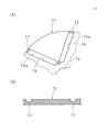
ところが、回転子積層鉄心に閉じた磁石挿入孔を形成すると、永久磁石の表裏に向かう磁束で、磁石挿入孔の外周部に磁気通路を形成し、回転子の磁気的効率が下がる。そこで、図4(A)、(B)に示すように、回転子積層鉄心を形成する鉄心片72の磁石挿入孔70の端部と外周との間に形成されるブリッジ部71をプレス加工によって塑性変形させて、その部分の厚みを他の部分より薄くすることによって、トルク変動の増大を防ぎ、漏れ磁束を低減してモータの効率を上げることが提案されている(特許文献2、特許文献3参照)。なお、70aは永久磁石を、73は軸孔を示す。
In recent years, as shown in
However, when a closed magnet insertion hole is formed in the rotor laminated iron core, a magnetic path is formed in the outer peripheral portion of the magnet insertion hole by the magnetic flux directed to the front and back of the permanent magnet, and the magnetic efficiency of the rotor is lowered. Therefore, as shown in FIGS. 4A and 4B, the
しかしながら、図5(A)、(B)に示すように、特許文献2記載の回転子積層鉄心を形成する鉄心片72を、順送り金型で打ち抜き加工して形成する場合、特に、ブリッジ部71の形成において、鉄心片72の上面側から薄肉加工を施したものでは、外形抜きの際に、パンチ74とブリッジ部71との間に隙間77が生じるので、切断中にパンチ74がブリッジ部71に当接しない状態があり、ブリッジ部71が径方向外側(鉄心片72の外周縁側)に変形するという問題が発生する。ここで、75はダイを、78はストリッパを示す。また、ブリッジ部71が鉄心片72の外周縁と磁石挿入孔70に渡って形成されている場合は、磁石挿入孔70にも変形が伝わるという問題もあった。
なお、このような問題は、磁石挿入孔のみでなく鉄心片に形成する他の抜き孔においても同様に発生する問題である。
However, as shown in FIGS. 5A and 5B, when the
Such a problem occurs not only in the magnet insertion hole but also in other punch holes formed in the iron core piece.
本発明はかかる事情に鑑みてなされたもので、鉄心片の打ち抜き加工時に抜き孔と外周縁との間に形成したブリッジ部の変形を無くした積層鉄心の製造方法を提供することを目的とする。 The present invention has been made in view of such circumstances, and an object of the present invention is to provide a method for manufacturing a laminated core that eliminates deformation of a bridge portion formed between a punched hole and an outer peripheral edge during punching of the core piece. .
前記目的に沿う第1の発明に係る積層鉄心の製造方法は、外周部にコイニング加工によって薄肉のブリッジ部が形成された鉄心片を薄板条材から順次打ち抜き形成し、打ち抜かれた前記鉄心片を積層する積層鉄心の製造方法において、
前記ブリッジ部を形成するコイニング加工を上方から行う工程と、
前記ブリッジ部を形成した後、前記ブリッジ部に嵌入する突出部を有する外形抜きパンチと、該外形抜きパンチと対となるダイを用いて前記薄板条材から前記鉄心片を下方に打ち抜く工程とを有する。
The method for manufacturing a laminated core according to the first aspect of the present invention is such that a core piece having a thin bridge portion formed on the outer peripheral portion by coining is sequentially punched from a thin strip material, and the punched core piece is In the manufacturing method of the laminated core to be laminated,
Performing coining from above to form the bridge portion;
After forming the bridge portion, a step of punching out the outer shape having a projecting portion that fits into the bridge portion, and a step of punching the core piece downward from the sheet material using a die paired with the shape punch. Have.
第1の発明に係る積層鉄心の製造方法において、前記ブリッジ部は抜き孔と前記鉄心片の外周縁との間に形成されているのが好ましい。 In the method for manufacturing a laminated core according to the first aspect of the present invention, it is preferable that the bridge portion is formed between a hole and an outer peripheral edge of the core piece.
第2の発明に係る積層鉄心の製造方法は、半径方向外側領域に抜き孔を、外周縁と前記抜き孔との間に薄肉のブリッジ部を有する鉄心片を薄板条材から順次打ち抜き、打ち抜かれた前記鉄心片を積層する積層鉄心の製造方法において、
前記ブリッジ部を前記鉄心片の上方からコイニング加工を行って形成する工程と、
前記抜き孔を上方からの孔抜きパンチによる打ち抜き加工によって形成する工程と、
前記ブリッジ部に嵌入する突出部を備えて下降する外形抜きパンチによって、前記薄板条材から前記鉄心片を打ち抜き、ダイ内に積層する工程とを有する。
According to a second aspect of the present invention, there is provided a method for manufacturing a laminated iron core, in which punched holes are formed in a radially outer region, and core pieces having a thin bridge portion between an outer peripheral edge and the punched holes are sequentially punched from a thin strip. In the manufacturing method of the laminated core in which the iron core pieces are laminated,
Forming the bridge portion by performing coining from above the iron core piece;
Forming the punched hole by punching with a punched hole from above;
A step of punching out the core pieces from the thin strip material and laminating them in a die by an outer shape punch having a projecting portion fitted into the bridge portion and descending.
第3の発明に係る積層鉄心の製造方法は、半径方向外側領域に抜き孔を、外周縁と前記抜き孔との間に薄肉のブリッジ部を有する鉄心片を薄板条材から順次打ち抜き、打ち抜かれた前記鉄心片を積層する積層鉄心の製造方法において、
前記ブリッジ部を前記鉄心片の上方からコイニング加工を行って形成する工程と、
下位置に配置された外形抜きパンチと該外形抜きパンチと対となって上位置に配置されたダイとを用いて、前記薄板条材から前記鉄心片を上方に打ち抜く工程とを有する。
According to a third aspect of the present invention, there is provided a method for manufacturing a laminated iron core, wherein a punched hole is formed in a radially outer region, and a core piece having a thin bridge portion between an outer peripheral edge and the punched hole is sequentially punched from a thin strip. In the manufacturing method of the laminated core in which the iron core pieces are laminated,
Forming the bridge portion by performing coining from above the iron core piece;
A step of punching the core piece upward from the thin strip material by using an outer punch arranged at the lower position and a die disposed at the upper position as a pair with the outer punch.
第3の発明に係る積層鉄心の製造方法において、前記ブリッジ部の形成の後に、該ブリッジ部に一部連続する前記抜き孔を上方からの孔抜きパンチによって形成するのが好ましい。 In the method for manufacturing a laminated core according to the third aspect of the invention, it is preferable that after the bridge portion is formed, the punched hole partially continuous with the bridge portion is formed by a punch punch from above.
第1〜第3の発明に係る積層鉄心の製造方法において、前記積層鉄心は回転子積層鉄心であって、前記鉄心片の半径方向外側に形成される前記抜き孔は磁石挿入孔であるのが好ましい。 In the method for manufacturing a laminated core according to the first to third inventions, the laminated core is a rotor laminated core, and the punched hole formed on the outer side in the radial direction of the core piece is a magnet insertion hole. preferable.
第1、第2の発明に係る積層鉄心の製造方法においては、外形抜きパンチにブリッジ部に嵌入する突出部を備えているので、外形抜きパンチとブリッジ部の間に隙間を生じることがなく、突出部がブリッジ部を支持するので、ブリッジ部の変形(特に、径方向外側への変形)が無くなるか減少する。 In the manufacturing method of the laminated core according to the first and second inventions, since the outer punch is provided with a protruding portion that fits into the bridge portion, there is no gap between the outer punch and the bridge portion, Since the protruding portion supports the bridge portion, deformation of the bridge portion (particularly, deformation outward in the radial direction) is eliminated or reduced.
また、第3の発明に係る積層鉄心の製造方法においては、コイニング加工によって形成された薄肉のブリッジ部の底面(平坦面)が鉄心片の下側に形成され、下から外形抜きを行うので、外形抜きパンチとブリッジ部の間に隙間を生じることなく、外形抜きパンチがブリッジ部を支持するので、ブリッジ部に曲げ力が掛からず、ブリッジ部の変形が無くなるか減少する。 Moreover, in the manufacturing method of the laminated core according to the third invention, the bottom surface (flat surface) of the thin-walled bridge portion formed by coining is formed on the lower side of the core piece, and the outer shape is removed from below. Since the external punch supports the bridge portion without generating a gap between the external punch and the bridge portion, no bending force is applied to the bridge portion, and deformation of the bridge portion is eliminated or reduced.
特に第2、第3の発明に係る積層鉄心の製造方法において、抜き孔の形成を上からの孔抜きパンチによって行う場合、抜き孔のスクラップ片に形成されたブリッジ部は折れ曲がるが、鉄心片(製品)には折れ曲がりや変形が発生しない。 In particular, in the method for manufacturing a laminated core according to the second and third inventions, when the punched hole is formed by punching punches from above, the bridge portion formed in the scrap piece of the punched hole is bent, but the core piece ( The product is not bent or deformed.
第1〜第3の発明に係る積層鉄心の製造方法において、積層鉄心を回転子積層鉄心とし、抜き孔を磁石挿入孔とした場合は、磁石挿入孔に挿入される永久磁石の磁気的効率が上昇する。 In the method for manufacturing a laminated core according to the first to third inventions, when the laminated core is a rotor laminated core and the punched hole is a magnet insertion hole, the magnetic efficiency of the permanent magnet inserted into the magnet insertion hole is high. To rise.
続いて、添付した図面を参照しながら、本発明を具体化した実施の形態について説明する。
本発明の第1の実施の形態に係る積層鉄心の製造方法においては、必要とする鉄心片10(図1(C)参照)の形成位置を決めるための複数のパイロット孔(図示せず)を珪素鋼板からなる薄板条材11の幅方向両側に形成する。このパイロット孔を基準にして、軸孔12等を打ち抜き形成する。軸孔12の加工は最初に行ってもよいし、以下に説明するコイニング加工の後に行ってもよい。
Next, embodiments of the present invention will be described with reference to the accompanying drawings.
In the method for manufacturing a laminated core according to the first embodiment of the present invention, a plurality of pilot holes (not shown) for determining the formation position of the required core piece 10 (see FIG. 1C) are provided. It forms on the both sides of the width direction of the
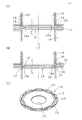
パイロット孔によって、鉄心片10の半径方向外側領域に形成する複数の磁石挿入孔(抜き孔の一例)13、その半径方向外側(磁石挿入孔13と外周縁との間、外周部を含む)に形成される薄肉のブリッジ部14、図示しないかしめ部の形成位置がそれぞれ決定される。この実施の形態では、図1(A)に示すように、薄板条材11の所定位置に最初にコイニング加工によりブリッジ部14を形成する。
A plurality of magnet insertion holes (an example of a punch hole) 13 formed in the radially outer region of the
薄板条材11にコイニング加工を行うと薄板条材11が歪むので、コイニング加工(押し潰し加工)を最初に行う。コイニング加工は薄板条材11の一部に塑性加工を行ってその部分を薄くする技術であり、コイニング後の厚みは、薄板条材11の厚みの50〜80%程度とするのがよい。なお、以上の工程は、以下に説明する本発明の第2、第3の実施の形態に係る積層鉄心の製造方法においても同様である。
When coining is performed on the
薄板条材11に対するコイニング加工は、薄板条材11の表側(上方)から行う。即ち、下方に突出する膨出部を所定箇所に有する上型と上面が平坦な下型とを用い(図示せず)、下型を押し上げ又は上型を押し下げることによって、薄板条材11の所定位置にブリッジ部14を形成する。このブリッジ部14は上面に窪み部16を有し、ブリッジ部14の上面(即ち、窪み部16の底面)は鉄心片10の表面に平行となっている。図1に示すように、薄板条材11に形成されたブリッジ部14は、鉄心片10の円形の外周縁17を超えて形成されている。
この状態で、薄板条材11の鉄心片10の形成領域でかつ鉄心片10の半径方向外側領域に、必要な数の磁石挿入孔13とかしめ部をプレス加工によって形成する。
The coining process for the
In this state, a necessary number of
かしめ部の形成にあっては、従来方法に従い、最初の(底位置にある)鉄心片10にはかしめ貫通孔を、その上に載る鉄心片10は通常のかしめ部(例えば、Vかしめ)を形成する。なお、本実施の形態では鉄心片同士の積層手段(結合手段)としてかしめを用いて説明したが、これに限らず接着あるいは溶接等の他の積層手段を用いてもよく、積層は金型内、金型外のいずれで行ってもよい(以下の実施の形態においても同じ)。
In the formation of the caulking portion, according to the conventional method, the first core piece 10 (at the bottom position) has a caulking through hole, and the
この後、図1(B)に示すように、下降する外形抜きパンチ18を用いて薄板条材11から順次鉄心片10をダイ19内に抜き落とし、ダイ19内(正確は、スクイズリング)でかしめ積層する。ここで、外形抜きパンチ18の底面には、鉄心片10の外周縁17の内側領域にあるブリッジ部14に符合(嵌入)する突出部18aが設けられている。突出部18aの高さもブリッジ部14(窪み部16)の深さに一致する。
Thereafter, as shown in FIG. 1 (B), the
図1は突出部18aを有する外形抜きパンチ18及びダイ19を用いて、鉄心片10をダイ19内に抜き落とす前後の動作状態を示し、20はストリッパを示し、図1(C)は外形抜きパンチ18とダイ19によって外周抜きされた鉄心片10の表側を示す。なお、突出部18aの半径方向外側は、この鉄心片10の外周円(外周縁17)と一致し、平面視して円形のダイ19と組合わさって刃物を形成している。
FIG. 1 shows an operation state before and after the
以上に説明した第1の実施の形態に係る積層鉄心の製造方法においては、外形抜きパンチ18の底部に突出部18aを有し、鉄心片10の下方への抜き落とし時には、ブリッジ部14に突出部18aが当接しているので、ブリッジ部14に曲げが発生せず、鉄心片10にあるブリッジ部14に変形が生じない。一方、鉄心片10の半径方向外側に位置するブリッジ部14はスクラップ片21の一部となるため、鉄心片10の精度には影響しない。
In the manufacturing method of the laminated core according to the first embodiment described above, the protruding
次に、図2(A)、(B)、図3(A)、(B)を参照しながら、本発明の第2、第3の実施の形態に係る積層鉄心の製造方法について説明する。第1の実施の形態に係る積層鉄心の製造方法によって製造された鉄心片10と同一の構成要素には同一の番号を付して詳しい説明を省略する。
第1の実施の形態に係る積層鉄心の製造方法と同様な方法で、磁石挿入孔13と鉄心片10の外周縁17を連結する領域に、上方からコイニング加工を行い窪み部16を形成してブリッジ部14を形成する。
Next, a method for manufacturing a laminated core according to the second and third embodiments of the present invention will be described with reference to FIGS. 2 (A), 2 (B), 3 (A), and 3 (B). The same number is attached | subjected to the component same as the
In a method similar to the method for manufacturing the laminated iron core according to the first embodiment, a
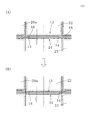
この後、図3(A)、(B)に示す工程を経て、磁石挿入孔13を形成する。磁石挿入孔13を、下降する孔抜きパンチ22と静止したダイ23とによって上方から打ち抜くと、磁石挿入孔13の端部まで延長したブリッジ部14が折れ曲がる(屈曲する)。これは、磁石挿入孔13に隣接するブリッジ部14の下方の支えがないので、磁石挿入孔13を形成する場合に発生するスクラップ片24によって下方に引っ張られるからである。なお、スクラップ片24は製品でもないので、スクラップ片24の一部が変形しても特に問題はない。なお、図3において、20aはストリッパを示す。(以上、本発明の第3の実施の形態に係る積層鉄心の製造方法)。
Thereafter, the
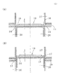
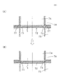
次に、鉄心片10を図2(A)、(B)に示す方法で、薄板条材11から分離する。この場合、外形抜きパンチ26は下型に配置されて昇降し、外形抜きパンチ26と対となるダイ27は上型にある。ダイ27は薄板条材11の通路を確保するため、僅少の範囲で昇降するのが好ましい。
薄板条材11を所定の位置にパイロットピンで位置決めし、下から上方に向けて外形抜きパンチ26を上昇させる。
Next, the
The
これによって、鉄心片10は薄板条材11から分離され、ブリッジ部14も鉄心片10側とスクラップ片29側とに分離されるが、鉄心片10側のブリッジ部14は天井面が平坦な外形抜きパンチ26によって支持されるので、変形が生じない。一方、スクラップ片29側のブリッジ部14は変形するが、製品ではないので特に支障はない。
Thereby, the
この後、鉄心片10はダイ27内に積層され、各鉄心片10はかしめ、接着剤、溶接等の接合手段で連結される。なお、図2においては、30はストリッパを示す。なお、以上の実施の形態においては、パイロット孔の形成、中央の円形抜き孔(例えば、軸孔)、必要な場合のかしめ部の形成は周知であるので、説明を省略した(以上、本発明の第2の実施の形態に係る積層鉄心の製造方法)。
Thereafter, the
本発明は前記した実施の形態に限定されるものではなく、本発明の要旨を変更しない範囲でその構成を変更することもできる。例えば、磁石挿入孔等の形状、個数は任意であり、更にブリッジ部の形状、位置も上記した実施の形態に限定されるものではない。
また、本発明は回転子積層鉄心に限らず、外周部にブリッジ部を形成するのであれば、固定子積層鉄心にも適用することができる。
また、抜き孔としては、重量軽減用の貫通孔も含む。
The present invention is not limited to the above-described embodiment, and the configuration thereof can be changed without changing the gist of the present invention. For example, the shape and number of magnet insertion holes and the like are arbitrary, and the shape and position of the bridge portion are not limited to the above embodiment.
Further, the present invention is not limited to the rotor laminated core, and can be applied to a stator laminated core as long as a bridge portion is formed on the outer peripheral portion.
Further, the through hole includes a through hole for weight reduction.
10:鉄心片、11:薄板条材、12:軸孔、13:磁石挿入孔、14:ブリッジ部、16:窪み部、17:外周縁、18:外形抜きパンチ、18a:突出部、19:ダイ、20、20a:ストリッパ、21:スクラップ片、22:孔抜きパンチ、23:ダイ、24:スクラップ片、26:外形抜きパンチ、27:ダイ、29:スクラップ片、30:ストリッパ 10: Iron core piece, 11: Thin strip material, 12: Shaft hole, 13: Magnet insertion hole, 14: Bridge part, 16: Recessed part, 17: Outer peripheral edge, 18: Outlet punch, 18a: Protruding part, 19: Die, 20, 20a: Stripper, 21: Scrap piece, 22: Hole punch, 23: Die, 24: Scrap piece, 26: Outline punch, 27: Die, 29: Scrap piece, 30: Stripper
Claims (6)
前記ブリッジ部を形成するコイニング加工を上方から行う工程と、
前記ブリッジ部を形成した後、前記ブリッジ部に嵌入する突出部を有する外形抜きパンチと、該外形抜きパンチと対となるダイを用いて前記薄板条材から前記鉄心片を下方に打ち抜く工程とを有することを特徴とする積層鉄心の製造方法。 In the manufacturing method of the laminated core in which the core pieces in which the thin bridge portions are formed by the coining process on the outer peripheral portion are sequentially punched from the thin strip material, and the punched core pieces are stacked.
Performing coining from above to form the bridge portion;
After forming the bridge portion, a step of punching out the outer shape having a projecting portion that fits into the bridge portion, and a step of punching the core piece downward from the sheet material using a die paired with the shape punch. A method for producing a laminated iron core, comprising:
前記ブリッジ部を前記鉄心片の上方からコイニング加工を行って形成する工程と、
前記抜き孔を上方からの孔抜きパンチによる打ち抜き加工によって形成する工程と、
前記ブリッジ部に嵌入する突出部を備えて下降する外形抜きパンチによって、前記薄板条材から前記鉄心片を打ち抜き、ダイ内に積層する工程とを有することを特徴とする積層鉄心の製造方法。 In a manufacturing method of a laminated core in which a punched hole is formed in a radially outer region, a core piece having a thin bridge portion between an outer peripheral edge and the punched hole is sequentially punched from a thin strip, and the punched core pieces are stacked. ,
Forming the bridge portion by performing coining from above the iron core piece;
Forming the punched hole by punching with a punched hole from above;
A method of manufacturing a laminated core, comprising: a step of punching out the core pieces from the thin strip material and laminating them in a die by an outer shape punch having a projecting portion fitted into the bridge portion and descending.
前記ブリッジ部を前記鉄心片の上方からコイニング加工を行って形成する工程と、
下位置に配置された外形抜きパンチと該外形抜きパンチと対となって上位置に配置されたダイとを用いて、前記薄板条材から前記鉄心片を上方に打ち抜く工程とを有することを特徴とする積層鉄心の製造方法。 In a manufacturing method of a laminated core in which a punched hole is formed in a radially outer region, a core piece having a thin bridge portion between an outer peripheral edge and the punched hole is sequentially punched from a thin strip, and the punched core pieces are stacked. ,
Forming the bridge portion by performing coining from above the iron core piece;
And a step of punching the core piece upward from the thin strip material using a punching punch arranged at the lower position and a die arranged at the upper position as a pair with the punching punch. A method for manufacturing a laminated iron core.
Priority Applications (4)
| Application Number | Priority Date | Filing Date | Title |
|---|---|---|---|
| JP2014125546A JP6320857B2 (en) | 2014-06-18 | 2014-06-18 | Manufacturing method of laminated iron core |
| US14/742,012 US9641055B2 (en) | 2014-06-18 | 2015-06-17 | Method for manufacturing laminated iron core |
| CN201510341264.8A CN105322733B (en) | 2014-06-18 | 2015-06-18 | The manufacture method of laminated core |
| DE102015211190.3A DE102015211190A1 (en) | 2014-06-18 | 2015-06-18 | Method for producing a laminated iron core |
Applications Claiming Priority (1)
| Application Number | Priority Date | Filing Date | Title |
|---|---|---|---|
| JP2014125546A JP6320857B2 (en) | 2014-06-18 | 2014-06-18 | Manufacturing method of laminated iron core |
Publications (2)
| Publication Number | Publication Date |
|---|---|
| JP2016005404A true JP2016005404A (en) | 2016-01-12 |
| JP6320857B2 JP6320857B2 (en) | 2018-05-09 |
Family
ID=54768169
Family Applications (1)
| Application Number | Title | Priority Date | Filing Date |
|---|---|---|---|
| JP2014125546A Active JP6320857B2 (en) | 2014-06-18 | 2014-06-18 | Manufacturing method of laminated iron core |
Country Status (4)
| Country | Link |
|---|---|
| US (1) | US9641055B2 (en) |
| JP (1) | JP6320857B2 (en) |
| CN (1) | CN105322733B (en) |
| DE (1) | DE102015211190A1 (en) |
Cited By (1)
| Publication number | Priority date | Publication date | Assignee | Title |
|---|---|---|---|---|
| WO2022030584A1 (en) * | 2020-08-07 | 2022-02-10 | 株式会社アイシン | Manufacturing method of rotor for rotating electric machine, and manufacturing method of rotating electric machine |
Families Citing this family (5)
| Publication number | Priority date | Publication date | Assignee | Title |
|---|---|---|---|---|
| JP5764483B2 (en) * | 2011-12-05 | 2015-08-19 | 株式会社三井ハイテック | Manufacturing method of laminated iron core and shape of punched punch generated thereby |
| US20180233996A1 (en) | 2017-02-16 | 2018-08-16 | Ford Global Technologies, Llc | Methods for tuning magnetic properties of electrical steel cores for electrical devices |
| US10355537B2 (en) | 2017-03-27 | 2019-07-16 | Ford Global Technologies, Llc | Method for adjusting magnetic permeability of electrical steel |
| US11309776B2 (en) * | 2017-09-29 | 2022-04-19 | Aisin Corporation | Manufacturing method of core for rotary electric machine |
| CN111819775B (en) * | 2018-03-08 | 2023-05-26 | 日本电产株式会社 | Method for manufacturing rotor core component |
Citations (8)
| Publication number | Priority date | Publication date | Assignee | Title |
|---|---|---|---|---|
| JPH0560616U (en) * | 1992-01-24 | 1993-08-10 | 日立電線株式会社 | Press die for punching irregularly shaped cross-section strips |
| JP2003088012A (en) * | 2001-09-05 | 2003-03-20 | Asmo Co Ltd | Core sheet, manufacturing method therefor, stator, and motor |
| JP2005130604A (en) * | 2003-10-23 | 2005-05-19 | Nissan Motor Co Ltd | Electromagnetic steel plate body, rotor for rotary machine incorporating permanent magnet employing it, rotary machine incorporating permanent magnet, and vehicle employing rotary machine incorporating permanent magnet |
| JP2006050821A (en) * | 2004-08-05 | 2006-02-16 | Asmo Co Ltd | Magnet-embedded motor |
| JP2008042967A (en) * | 2006-01-11 | 2008-02-21 | Mitsui High Tec Inc | Resin sealing method of permanent magnet to laminated core of rotor |
| JP2009006357A (en) * | 2007-06-28 | 2009-01-15 | Toyota Motor Corp | Punching/press-working method and punch press die |
| US20100213785A1 (en) * | 2007-09-04 | 2010-08-26 | Mitsui High-Tec, Inc. | Laminated core and method for manufacturing the same |
| JP2012016090A (en) * | 2010-06-29 | 2012-01-19 | Asmo Co Ltd | Permanent magnet embedded motor |
Family Cites Families (6)
| Publication number | Priority date | Publication date | Assignee | Title |
|---|---|---|---|---|
| US6636137B1 (en) * | 1996-06-05 | 2003-10-21 | L.H. Carbide Corporation | Ignition coil assembly |
| DE10227129A1 (en) | 2002-06-18 | 2004-01-29 | Cornelius Peter | Electrical machine |
| WO2007080661A1 (en) | 2006-01-11 | 2007-07-19 | Mitsui High-Tec, Inc. | Method of resin sealing permanent magnets in laminated rotor core |
| WO2012060191A1 (en) * | 2010-11-04 | 2012-05-10 | アイシン精機株式会社 | Rotor of electric motor and manufacturing method thereof |
| JP2014036554A (en) * | 2012-08-10 | 2014-02-24 | Aisin Seiki Co Ltd | Rotor yoke and motor using the same |
| JP5697637B2 (en) * | 2012-09-21 | 2015-04-08 | 黒田精工株式会社 | Laminated core manufacturing method and laminated core manufacturing apparatus |
-
2014
- 2014-06-18 JP JP2014125546A patent/JP6320857B2/en active Active
-
2015
- 2015-06-17 US US14/742,012 patent/US9641055B2/en active Active
- 2015-06-18 CN CN201510341264.8A patent/CN105322733B/en active Active
- 2015-06-18 DE DE102015211190.3A patent/DE102015211190A1/en active Pending
Patent Citations (8)
| Publication number | Priority date | Publication date | Assignee | Title |
|---|---|---|---|---|
| JPH0560616U (en) * | 1992-01-24 | 1993-08-10 | 日立電線株式会社 | Press die for punching irregularly shaped cross-section strips |
| JP2003088012A (en) * | 2001-09-05 | 2003-03-20 | Asmo Co Ltd | Core sheet, manufacturing method therefor, stator, and motor |
| JP2005130604A (en) * | 2003-10-23 | 2005-05-19 | Nissan Motor Co Ltd | Electromagnetic steel plate body, rotor for rotary machine incorporating permanent magnet employing it, rotary machine incorporating permanent magnet, and vehicle employing rotary machine incorporating permanent magnet |
| JP2006050821A (en) * | 2004-08-05 | 2006-02-16 | Asmo Co Ltd | Magnet-embedded motor |
| JP2008042967A (en) * | 2006-01-11 | 2008-02-21 | Mitsui High Tec Inc | Resin sealing method of permanent magnet to laminated core of rotor |
| JP2009006357A (en) * | 2007-06-28 | 2009-01-15 | Toyota Motor Corp | Punching/press-working method and punch press die |
| US20100213785A1 (en) * | 2007-09-04 | 2010-08-26 | Mitsui High-Tec, Inc. | Laminated core and method for manufacturing the same |
| JP2012016090A (en) * | 2010-06-29 | 2012-01-19 | Asmo Co Ltd | Permanent magnet embedded motor |
Cited By (1)
| Publication number | Priority date | Publication date | Assignee | Title |
|---|---|---|---|---|
| WO2022030584A1 (en) * | 2020-08-07 | 2022-02-10 | 株式会社アイシン | Manufacturing method of rotor for rotating electric machine, and manufacturing method of rotating electric machine |
Also Published As
| Publication number | Publication date |
|---|---|
| CN105322733A (en) | 2016-02-10 |
| CN105322733B (en) | 2018-01-23 |
| US20150372572A1 (en) | 2015-12-24 |
| US9641055B2 (en) | 2017-05-02 |
| DE102015211190A1 (en) | 2015-12-24 |
| JP6320857B2 (en) | 2018-05-09 |
Similar Documents
| Publication | Publication Date | Title |
|---|---|---|
| JP6320857B2 (en) | Manufacturing method of laminated iron core | |
| JP6320856B2 (en) | Manufacturing method of laminated iron core | |
| JP5875746B2 (en) | Manufacturing method of stator core | |
| US8456057B2 (en) | Laminated stator core | |
| JP4681954B2 (en) | Manufacturing method of laminated iron core and laminated iron core | |
| JP6400833B2 (en) | Laminated core manufacturing method and laminated core manufacturing apparatus | |
| JP5860555B2 (en) | Manufacturing method of laminated iron core | |
| JP5358517B2 (en) | Manufacturing method of laminated iron core | |
| JP5688919B2 (en) | Manufacturing method of laminated iron core | |
| JP2015080412A5 (en) | ||
| JP2014176127A (en) | Laminated core and manufacturing method thereof | |
| JP2010178487A (en) | Manufacturing method for laminated core and forward metal mold device | |
| JP4989877B2 (en) | Manufacturing method of rotor laminated core | |
| KR101919561B1 (en) | Manufacturing method and manufacturing apparatus for layered iron core | |
| JP5297147B2 (en) | Manufacturing method of magnet mounted rotor core | |
| JP5486350B2 (en) | Stator laminated iron core and manufacturing method thereof | |
| JP5720407B2 (en) | Manufacturing method and manufacturing apparatus for rotor laminated core with permanent magnet | |
| JP2008278610A (en) | Progressive die assembly for manufacturing laminated core | |
| JP6568969B2 (en) | Laminated iron core | |
| JP2018038152A (en) | Method of manufacturing motor core and motor core | |
| JP5462675B2 (en) | Manufacturing method of laminated iron core | |
| JP2015082947A (en) | Method for manufacturing stator laminated iron core | |
| JP5390243B2 (en) | Manufacturing method of laminated iron core | |
| JP2019165521A (en) | Manufacturing method of core for rotary electric machine and manufacturing apparatus of the same | |
| JP2016077046A (en) | Manufacturing method of laminated core, and laminate |
Legal Events
| Date | Code | Title | Description |
|---|---|---|---|
| A621 | Written request for application examination |
Free format text: JAPANESE INTERMEDIATE CODE: A621 Effective date: 20170321 |
|
| A977 | Report on retrieval |
Free format text: JAPANESE INTERMEDIATE CODE: A971007 Effective date: 20171116 |
|
| A131 | Notification of reasons for refusal |
Free format text: JAPANESE INTERMEDIATE CODE: A131 Effective date: 20180109 |
|
| A521 | Request for written amendment filed |
Free format text: JAPANESE INTERMEDIATE CODE: A523 Effective date: 20180306 |
|
| TRDD | Decision of grant or rejection written | ||
| A01 | Written decision to grant a patent or to grant a registration (utility model) |
Free format text: JAPANESE INTERMEDIATE CODE: A01 Effective date: 20180327 |
|
| A61 | First payment of annual fees (during grant procedure) |
Free format text: JAPANESE INTERMEDIATE CODE: A61 Effective date: 20180404 |
|
| R150 | Certificate of patent or registration of utility model |
Ref document number: 6320857 Country of ref document: JP Free format text: JAPANESE INTERMEDIATE CODE: R150 |
|
| R250 | Receipt of annual fees |
Free format text: JAPANESE INTERMEDIATE CODE: R250 |
|
| R250 | Receipt of annual fees |
Free format text: JAPANESE INTERMEDIATE CODE: R250 |
|
| R250 | Receipt of annual fees |
Free format text: JAPANESE INTERMEDIATE CODE: R250 |
|
| R250 | Receipt of annual fees |
Free format text: JAPANESE INTERMEDIATE CODE: R250 |