JP2008278610A - Progressive die assembly for manufacturing laminated core - Google Patents
Progressive die assembly for manufacturing laminated core Download PDFInfo
- Publication number
- JP2008278610A JP2008278610A JP2007118120A JP2007118120A JP2008278610A JP 2008278610 A JP2008278610 A JP 2008278610A JP 2007118120 A JP2007118120 A JP 2007118120A JP 2007118120 A JP2007118120 A JP 2007118120A JP 2008278610 A JP2008278610 A JP 2008278610A
- Authority
- JP
- Japan
- Prior art keywords
- die
- core thin
- portions
- iron core
- thin plates
- Prior art date
- Legal status (The legal status is an assumption and is not a legal conclusion. Google has not performed a legal analysis and makes no representation as to the accuracy of the status listed.)
- Pending
Links
Images


Abstract
Description
本発明は、モータコア等の積層鉄心を製造するための順送り金型装置に係り、詳しくは、比較的簡易かつ低コストな構成を採りながら、積層鉄心の円滑な製造を可能とする技術に関する。 The present invention relates to a progressive mold apparatus for manufacturing a laminated core such as a motor core, and more particularly to a technique that enables a smooth production of a laminated core while adopting a relatively simple and low-cost configuration.
電動モータのコア等に用いられる積層鉄心は、通常、順送り金型に設置された上型のパンチと下型のダイとによって電磁鋼板のフープ材(帯状鋼板)から所定形状を連続的に打ち抜き、最終工程で薄板形状外形を打ち抜きし、外形を打ち抜きした鉄心薄板をダイ内に抜き込んで順次積層させながら一体固着させ、所定枚数毎に積層鉄心として取り出すことによって製造される。このような順送り金型では、鉄心薄板どうしを一体/固着させる手段として、各鉄心薄板に例えば半抜き加工によるかしめ手段(かしめ凸部またはかしめ凹部)を同位置の表裏に形成し、かしめ凸部をかしめ凹部に圧入させることによって重なり合った鉄心薄板を結合/一体化させる方法(かしめ結合方式)と、鉄心薄板を最終工程で外形を打ち抜きし、外形を打ち抜きした鉄心薄板を順次ダイ内に抜き込んだ際に、積層され下降してくる鉄心薄板の外周部に下型に配置したレーザ溶接装置により、レーザ光を照射することによって重なり合った鉄心薄板を結合/一体化させる方法(溶接結合方式)と、鉄心薄板の外周を打ち抜く前に鉄心薄板形状の所定位置(上面あるいは下面)に接着剤を塗布しておき、外形を打ち抜きした鉄心薄板を順次ダイ内に抜き込んだ際に、積層され下降してくる鉄心薄板を重なり合った鉄心薄板に押圧させて結合/一体化させる方法(接着結合方式)とが知られている。 A laminated iron core used for an electric motor core or the like is usually punched out continuously from a hoop material (strip-shaped steel plate) of an electromagnetic steel plate by an upper die punch and a lower die installed in a progressive die, It is manufactured by punching out a thin plate-shaped outer shape in the final process, drawing out the iron core thin plate with the outer shape punched out into a die, fixing them integrally while sequentially laminating them, and taking them out as a laminated core every predetermined number of sheets. In such a progressive die, as a means for integrally / fixing the iron core thin plates, caulking means (caulking convex portions or caulking concave portions) by, for example, half-punching are formed on the front and back of the same position on each iron thin plate. A method of joining / integrating overlapping core thin plates by caulking them into the recesses (caulking joining method), and punching out the outer shape of the core thin plate in the final process, and sequentially drawing out the core thin plates punched out of the outer shape into the die In this case, a method (welding method) for joining / integrating overlapping iron core thin plates by irradiating a laser beam with a laser welding device arranged in a lower mold on the outer periphery of the laminated thin iron core plates Before punching the outer periphery of the core thin plate, apply an adhesive to a predetermined position (upper surface or lower surface) of the core thin plate shape, When elaborate vent into the die, a method of coupling / integrated to by pressing the (adhesive bonding method) is known in the overlapping core sheet the core sheet coming to be stacked descends.
これらの各種結合方式を採用した順送り金型では、かしめ結合方式の場合には上述したかしめ凸部のかしめ凹部への圧入を確実に行わせるため、先に外形打抜きされた鉄心薄板を所定の保持力で保持する保持手段が必要となる。また、溶接結合方式においても、打ち抜かれた鉄心薄板どうしを密着させた状態で溶接するため、先に外形抜きされた鉄心薄板を所定の保持力でダイ側に保持する保持手段が必要となる。そして、接着結合方式においても同様に、打ち抜かれた鉄心薄板どうしを密着させた状態で接着させるため、先に外形抜きされた鉄心薄板を所定の保持力でダイ側に保持する保持手段が必要となる。 In the progressive die using these various coupling methods, in the case of the caulking coupling method, the iron core thin plate previously punched in the outer shape is held in place in order to ensure that the above-mentioned caulking convex portion is press-fitted into the caulking concave portion. A holding means for holding with force is required. Also in the welding connection method, since the punched iron core thin plates are welded in close contact with each other, a holding means for holding the iron core thin plate that has been punched out on the die side with a predetermined holding force is required. Similarly, in the adhesive bonding method, in order to bond the punched iron core thin plates in close contact with each other, it is necessary to have a holding means for holding the core thin plates that have been punched out on the die side with a predetermined holding force. Become.
このような保持手段としては、外形打抜きダイの下方に油圧駆動式や機械駆動式の受け台を配置し、この受け台によって鉄心薄板を支えるもの(受け台方式あるいは背圧方式と呼ばれる:特許文献1参照)と、外形打抜きダイの下方に外形打抜きダイの抜き孔と同一形状(あるいは、ダイの抜き孔より若干小さな形状)の保持孔を有するスクイズリング(保持リング)を配置し、このスクイズリングによって抜き込まれてくる鉄心薄板に側圧(鉄心薄板の外周面とスクイズリングの内周面との間の摩擦力)を付与するもの(スクイズリング方式:特許文献2参照)とが公知となっている。
受け台方式の順送り金型には、鉄心薄板に大きな保持力を与えられるため、鉄心薄板の確実な結合を実現できる反面、完成した積層鉄心を順送り金型から搬出する際に受け台を待避させなければならず、装置構成が複雑となって製作や保守に多くの時間とコストとを要する問題があった。 The cradle type progressive die gives a large holding force to the core thin plate, so that the core thin plate can be securely connected, but the cradle is retracted when the finished laminated core is unloaded from the progressive die. There is a problem that the configuration of the apparatus is complicated and a lot of time and cost are required for production and maintenance.
一方、スクイズリング方式の順送り金型では、受け台方式のような可動部が存在しないため、上述した製作や保守に係る問題は生じないが、外形打抜きダイとスクイズリングとが別体であることに起因する別種の問題があった。すなわち、外形打抜きダイの抜き孔とスクイズリングの保持孔とは互いの形状寸法が殆ど同一であるため、外形打抜きダイとスクイズリングとが微少にずれると、外形打抜きダイで打抜かれた鉄心薄板がスクイズリングに円滑に進入しなくなったり、鉄心薄板に付与される側圧が不均一になったりする等の虞がある。そこで、順送り金型の製作時においては、熟練した作業者が外形打抜きダイとスクイズリングとの位置合わせを1台ずつ厳密に行わざるを得ず、製作コストの増大や生産性の低下がもたらされていた。 On the other hand, in the squeeze ring type progressive die, there is no moving part like the cradle type, so the problems related to the production and maintenance mentioned above do not occur, but the external punching die and the squeeze ring are separate. There was another kind of problem due to In other words, since the shape and size of the punching hole of the outer punching die and the holding hole of the squeeze ring are almost the same, if the outer punching die and the squeeze ring are slightly displaced, the iron core sheet punched by the outer punching die is There is a risk that the squeeze ring may not enter smoothly, or the lateral pressure applied to the iron core thin plate may be uneven. Therefore, when manufacturing a progressive die, a skilled worker must strictly align the outer punching die and the squeeze ring one by one, resulting in an increase in manufacturing cost and a decrease in productivity. It had been.
また一方、スクイズリング方式の順送り金型においては、スクイズリングに複数の入れ子(側圧ピース)を組み込み、これら入れ子をスクイズリング内に出し入れして側圧を調整するものも存在する。しかしながら、このような順送り金型においても、側圧の微調整が完全でなかった場合、完成した積層鉄心に微少な倒れが生じる、直角度が許容範囲を外れる、外形打抜きダイやスクイズリング内に積層鉄心が詰まる等の虞があった。 On the other hand, there are some squeeze ring type progressive molds that incorporate a plurality of inserts (side pressure pieces) in the squeeze ring and adjust the side pressure by putting these inserts in and out of the squeeze ring. However, even in such a progressive die, if the fine adjustment of the side pressure is not complete, the finished laminated iron core will be slightly tilted, the perpendicularity will be out of the allowable range, and it will be laminated in the external punching die or squeeze ring. There was a risk of clogging the iron core.
本発明は、このような背景に鑑みなされたものであり、比較的簡易かつ低コストな構成を採りながら、積層鉄心の円滑な製造を可能とする積層鉄心製造用順送り金型装置を提供することを目的とする。 The present invention has been made in view of such a background, and provides a progressive mold apparatus for manufacturing a laminated core that enables smooth production of the laminated core while adopting a relatively simple and low-cost configuration. With the goal.
請求項1の発明は、鉄心薄板の外形を打ち抜いてダイ内に抜き込み、当該ダイに続いて配置されるスクイズリング内で抜き込まれた鉄心薄板に側圧を加えることによって積層方向に押圧力を付与する方式の順送り金型装置であって、該外形打ち抜きダイとスクイズリングとが一体形成されており、外形を打ち抜くダイを構成する所定深さの抜き孔部分に続くスクイズリングに相当する抜き孔部分において、内周形状の一部へ抜き方向に逃げ部を形成し、残ったストレート部で抜き込まれてくる鉄心薄板へ側圧を付与させるように構成したことを特徴とする。 In the invention of claim 1, the outer shape of the iron core thin plate is punched out into the die, and the pressing force is applied in the stacking direction by applying a side pressure to the iron core thin plate extracted in the squeeze ring arranged following the die. This is a progressive die device of the applying method, in which the outer punching die and the squeeze ring are integrally formed, and a punching hole corresponding to a squeeze ring following a punching hole portion of a predetermined depth constituting a die for punching the outer shape. In the portion, a relief portion is formed in a part of the inner peripheral shape in the drawing direction, and a side pressure is applied to the iron core thin plate drawn out by the remaining straight portion.
請求項1の発明によれば、外形打抜きダイと側圧付与手段であるスクイズリングとが一体に形成されているため、従来装置で必要とされたいた位置合わせ作業が不要となるとともに、構成部品点数が減少し、位置ずれに起因する種々の不具合も発生しなくなる。また、本発明をかしめ結合方式の順送り金型装置に適用した場合には、側圧による保持力がかしめ部により強固に作用しやすくなり、円滑な結合/一体化が実現される。また、本発明を溶接結合方式や接着結合方式の順送り金型装置に適用した場合にも、重なり合う鉄心薄板どうしの密着性が高まり、より結合性の高い積層鉄心を提供できる。 According to the first aspect of the present invention, since the outer shape punching die and the squeeze ring as the side pressure applying means are integrally formed, the alignment work required in the conventional apparatus is not necessary, and the number of components is reduced. Decreases, and various problems caused by misalignment do not occur. In addition, when the present invention is applied to a caulking and joining type progressive die apparatus, the holding force due to the side pressure tends to more strongly act on the caulking portion, thereby realizing smooth joining / integration. Further, even when the present invention is applied to a progressive joining die apparatus of a welding connection method or an adhesive connection method, the adhesiveness between overlapping iron core thin plates is increased, and a laminated iron core with higher bondability can be provided.
以下、図面を参照して、本発明を適用した順送り金型装置(積層鉄心製造装置)の実施形態を詳細に説明する。なお、実施形態の順送り金型は、電動モータの固定子(ステータ)に用いられる分割型の積層鉄心を製造するものである。 Hereinafter, an embodiment of a progressive metal mold apparatus (laminated core manufacturing apparatus) to which the present invention is applied will be described in detail with reference to the drawings. In addition, the progressive metal mold | die of embodiment manufactures the division | segmentation type | mold laminated iron core used for the stator (stator) of an electric motor.
[第1実施形態]
図1は第1実施形態に係る順送り金型装置の外径打抜き部を示す縦断面図であり、図2は第1実施形態に係る積層鉄心を示す斜視図である。また、図3は第1実施形態に係る外形打抜きダイの平面図であり、図4は図3中のIV−IV断面図であり、図5は第1実施形態に係る外形打抜きダイの内面を示す斜視図である。
[First Embodiment]
FIG. 1 is a longitudinal sectional view showing an outer diameter punching portion of a progressive die apparatus according to the first embodiment, and FIG. 2 is a perspective view showing a laminated iron core according to the first embodiment. 3 is a plan view of the outer punching die according to the first embodiment, FIG. 4 is a sectional view taken along the line IV-IV in FIG. 3, and FIG. 5 shows the inner surface of the outer punching die according to the first embodiment. It is a perspective view shown.
<第1実施形態の構成>
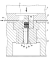
図1に示すように、第1実施形態に係る順送り金型装置1は、その外径打抜き部2において、上型3に保持された外形打抜きパンチ(以下、単に外形パンチと記す)11と、外形パンチ11と伴に下降してフープ材(帯状鋼板)Wを押さえるストリッパプレート12と、下型4に保持された外形打ち抜きダイ(以下、単に外形ダイと記す)13とを備えている。下型4の上面には、複数本のコラム14が立設されており、上型3およびストリッパプレート12がこれらコラム14に案内されて上下に摺動する。なお、外形ダイ13は、下型4に締結されたダイプレート15によって下型4に固定されている。
<Configuration of First Embodiment>
As shown in FIG. 1, a progressive die apparatus 1 according to the first embodiment includes an outer punching punch (hereinafter simply referred to as an outer punch) 11 held by an
図2に示すように、積層鉄心16は、図示しない巻線が施される磁極部16aと、外周側部分を形成する円弧状の継鉄部(ヨーク)16bとを有しており、1枚目の鉄心薄板17と2枚目以降の鉄心薄板18とを外形ダイ13内で積層/一体化させることにより製造される。1枚目の鉄心薄板17には、磁極部17aおよび継鉄部17bにそれぞれ計量孔(貫通孔)19a,19bが形成されている。また、2枚目以降の鉄心薄板18には、磁極部18aおよび継鉄部18bにそれぞれかしめ凸部20a,20bとかしめ凹部21a,21bとが形成されている。
As shown in FIG. 2, the laminated
図3〜図5に示すように、外形ダイ13は、略直方体形状を呈しており、フープ材Wから鉄心薄板17,18を打抜くためのダイ部31と、該ダイ部31に続いて形成され、打ち抜かれた鉄心薄板17,18に側圧を付与するスクイズリング部32とからなっている。このダイ部31には、鉄心薄板17,18の外形形状と同一形状のダイ孔33が形成されている。また、スクイズリング部32には、鉄心薄板17,18の外周側面の複数箇所、第1実施形態においては、磁極部17a,18aに摺接し、ダイ部31の内面と同一平面に形成されたストレート部34,35と、鉄心薄板17,18の継鉄部17b,18bに摺接し、ダイ部31の内面と同一平面に形成されたストレート部36と、更に鉄心薄板17,18の内径部17c、18cに摺接し、ダイ部31の内面と同一平面に形成されたストレート部37とが形成されており、側圧付与に使用される。そして、これらストレート部34〜37以外は、下方に向かって拡がる緩やかなテーパをなす逃げ部38となっている。
As shown in FIGS. 3 to 5, the
<第1実施形態の作用>
順送り金型装置1が作動を開始すると、フープ材Wは、順送り金型装置1内で間欠送りされながら、種々の打抜き加工や半抜き加工が施された後に外径打抜き部2に進入する。外径打抜き部2において上型3が下降すると、図6に示すように、フープ材Wがストリッパプレート12と下型4とによって挟持された後、外形パンチ11が外形ダイ13に嵌入することによりフープ材Wから鉄心薄板17,18が順次打抜かれる。
<Operation of First Embodiment>
When the progressive die apparatus 1 starts operating, the hoop material W enters the outer diameter punched
図7(図6中のVII部拡大図)に示すように、外形ダイ13内に抜き込まれた2枚目以降の鉄心薄板18は、それまでに抜き込まれた鉄心薄板17,18がスクイズリング部32の内周に形成されているストレート部34〜37で側圧が付与された状態で保持されている上面に外形パンチ11によって下向きに押し下げられるため、その押し下げ力と先にストレート部34〜37内に積層されている鉄心薄板17,18の側面に加わっている側圧とにより計量孔19a,19bやかしめ凹部21a,21bにかしめ凸部20a,20bがしっかりと嵌入する。このとき、ストレート部34〜37はダイ部31と一体成形されていることから、ダイ部31とストレート部34〜37との間には段差等が存在せず、鉄心薄板17,18の円滑な進行(下降)が実現される。
As shown in FIG. 7 (enlarged view of the VII portion in FIG. 6), the second and subsequent iron core
図8(図7中のVIII−VIII断面図)に示すように、鉄心薄板17,18のかしめ部(計量孔19a、かしめ凸部20a、かしめ凹部21a)が形成されている位置の付近に側圧を付与するストレート部34〜37が配置されていることにより、かしめ部により効果的に押し下げ力(かしめ力)を作用させることができる。すなわち、ストレート部34,35は、鉄心薄板17,18の磁極部17a,18a側のかしめ部(計量孔19a、かしめ凸部20a、かしめ凹部21a)の近傍に設けてあり、また、ストレート部36は、鉄心薄板17,18の継鉄部17b,18b側のかしめ部(計量孔19b、かしめ凸部20b、かしめ凹部21b)の近傍に設けてある。なお、1枚目の鉄心薄板17は、フープ材Wから所定枚数(本実施形態では、12枚)ごとに計量孔19a,19bが打ち抜かれ、これにより積層厚みが決定される。
As shown in FIG. 8 (VIII-VIII cross-sectional view in FIG. 7), the side pressure is near the position where the caulking portions (
第1実施形態では、上述した構成を採ったことにより、従来装置で問題となっていた順送り金型の製作時に必要とされたいた外形打ち抜きダイとスクイズリング間の位置合わせが不要となるとともに、構成部品点数が減少し、外形打ち抜きダイとスクイズリングとの位置ずれに起因する種々の不具合も発生しなくなる。また、スクイズリング部32の全内周ではなく、部分内面のみを側圧付与用のストレート部34〜37として形成したため、積層されてくる鉄心薄板17,18に側圧が効果的に作用し、より密着性が向上するという効果も得られた。
In the first embodiment, by adopting the above-described configuration, it becomes unnecessary to align the outer shape punching die and the squeeze ring, which was necessary when manufacturing the progressive die, which has been a problem in the conventional apparatus, The number of component parts is reduced, and various problems caused by misalignment between the outer punching die and the squeeze ring are not generated. In addition, since only the partial inner surface of the
なお、第1実施形態の構成は、前述した接着結合方式の順送り金型装置にもそのまま適用可能である。すなわち、接着結合方式の順送り金型装置の場合には、外形打ち抜き工程より前の工程で鉄心薄板17,18の上面あるいは下面の所定箇所に接着剤を塗布され、外形打ち抜き工程で外形ダイ13内に鉄心薄板17,18が抜き込まれると、スクイズリング部32によって側圧を付与されることにより鉄心薄板17,18どうしが密着して一体化される。
Note that the configuration of the first embodiment can also be applied to the above-described adhesive bonding type progressive die apparatus. That is, in the case of an adhesive bond type progressive die apparatus, an adhesive is applied to a predetermined location on the upper surface or the lower surface of the iron core
[第2実施形態]
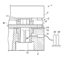
図9は第2実施形態に係る順送り金型装置の外径打抜き部を示す縦断面図である。第2実施形態は、本発明を溶接結合方式の順送り金型装置に適用したものであり、その全体構成は上述した第1実施形態と略同様であるため、同一の部材には同一の符号を付すとともい、重複する説明を省略する。
[Second Embodiment]
FIG. 9 is a longitudinal sectional view showing an outer diameter punching portion of the progressive die apparatus according to the second embodiment. In the second embodiment, the present invention is applied to a welding die type progressive die apparatus, and the overall configuration is substantially the same as that of the first embodiment described above. When attached, redundant description is omitted.
図9に示すように、外形ダイ13にはスクイズリング部32の内周面に貫通する複数(図9には、1つのみ示す)の貫通孔50が形成されており、これら貫通孔50および下型4内にレーザ光を照射するための光ファイバ射出ユニット51が埋設されている。光ファイバ射出ユニット51には、レーザ制御装置52に制御されるレーザ発振器53が接続されており、スクイズリング部32の内周にレーザ光が照射されるようになっている。
As shown in FIG. 9, the
第2実施形態は、鉄心薄板17,18が外形ダイ13内に打ち込まれ積層されてゆき、外形ダイ13のスクイズリング部32における光ファイバ射出ユニット51の位置まで下降したときに、重なり合う鉄心薄板17,18間にレーザ光が照射されて溶接/一体化されるもので、照射部のスポット径の大きさと鉄心薄板17,18の厚みとにより、1枚ごと、あるいは所定枚数ごとにレーザ光を照射することで、積層鉄心を製造することができる。
In the second embodiment, the iron core
[一部変形例]
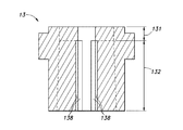
図10は一部変形例に係る外形打抜きダイの縦断面図である。一部変形例は、上記実施形態に対し、外形打ち抜きダイの逃げ部の形状のみを変更したものである。すなわち、上記実施形態ではダイ部の下端から下方に向かって拡がる緩やかなテーパをなす逃げ部を採用したが、一部変形例においては、ダイ部131を過ぎた位置からスクイズリング部132の全長にわたって同一深さの逃げ部138が形成されている。
[Partial modification]
FIG. 10 is a longitudinal sectional view of an external punching die according to a partially modified example. The partial modification is obtained by changing only the shape of the relief portion of the outer punching die from the above embodiment. That is, in the above-described embodiment, the escaping portion having a gentle taper extending downward from the lower end of the die portion is employed. An
以上で具体的実施形態や一部変形例の説明を終えるが、本発明の態様はこれら実施形態や一部変形例に限られるものではない。例えば、上記実施形態では電動モータの固定子用の分割型積層鉄心を製造する装置に本発明を適用したが、本発明は、電動モータの回転子用の分割型積層鉄心を製造する装置に適用してもよいし、発電機の固定子や回転子用の分割型積層鉄心を製造する装置に適用してもよい。また、上記実施形態では単一の磁極部を有する分割型積層鉄心を製造する装置に本発明を適用したが、本発明は、複数(例えば、2〜4個)の磁極部を備えた分割型積層鉄心を製造する装置に適用してもよいし、非分割型(環状)の積層鉄心を製造する装置に適用してもよい。また、上記実施形態の鉄心薄板は2箇所のかしめ部を有するものとしたが、かしめ部は、2箇所以外であってもよいし、凹部に凸部を嵌入させる以外の形態をとるものであってもよい。その他、順送り金型の具体的レイアウト等についても、上記実施形態での例示に限られるものではなく、本発明の主旨を逸脱しない範囲であれば適宜変更可能である。 This is the end of the description of the specific embodiments and some variations, but the aspects of the present invention are not limited to these embodiments and some variations. For example, in the above embodiment, the present invention is applied to an apparatus for manufacturing a split laminated core for a stator of an electric motor. However, the present invention is applied to an apparatus for manufacturing a split stacked core for an electric motor rotor. Alternatively, the present invention may be applied to an apparatus for manufacturing a split laminated core for a generator stator or rotor. In the above embodiment, the present invention is applied to an apparatus for manufacturing a split-type laminated core having a single magnetic pole portion. However, the present invention is a split-type including a plurality of (for example, 2 to 4) magnetic pole portions. You may apply to the apparatus which manufactures a laminated iron core, and may apply to the apparatus which manufactures a non-dividing type (annular) laminated iron core. Moreover, although the iron core thin plate of the said embodiment shall have two crimping parts, a crimping part may be other than two places, and may take forms other than inserting a convex part in a recessed part. May be. In addition, the specific layout or the like of the progressive die is not limited to the example in the above embodiment, and can be changed as appropriate without departing from the gist of the present invention.
1 順送り金型装置
3 上型
4 下型
11 外形打抜きパンチ
13 外形打抜きダイ
16 積層鉄心
17 鉄心薄板
17a 磁極部
17b 継鉄部
17c 内径部
18 鉄心薄板
18a 磁極部
18b 継鉄部
18c 内径部
19a 計量孔(かしめ部)
19b 計量孔(かしめ部)
20a かしめ凸部(かしめ部)
20b かしめ凸部(かしめ部)
21a かしめ凹部(かしめ部)
21b かしめ凹部(かしめ部)
34〜37 ストレート部
38 逃げ部
138 逃げ部
W フープ材(帯状金属薄板)
DESCRIPTION OF SYMBOLS 1
19b Measuring hole (caulking part)
20a Caulking convex portion (caulking portion)
20b Caulking convex portion (caulking portion)
21a Caulking concave portion (caulking portion)
21b Caulking recess (caulking part)
34-37
Claims (1)
Priority Applications (1)
| Application Number | Priority Date | Filing Date | Title |
|---|---|---|---|
| JP2007118120A JP2008278610A (en) | 2007-04-27 | 2007-04-27 | Progressive die assembly for manufacturing laminated core |
Applications Claiming Priority (1)
| Application Number | Priority Date | Filing Date | Title |
|---|---|---|---|
| JP2007118120A JP2008278610A (en) | 2007-04-27 | 2007-04-27 | Progressive die assembly for manufacturing laminated core |
Publications (1)
| Publication Number | Publication Date |
|---|---|
| JP2008278610A true JP2008278610A (en) | 2008-11-13 |
Family
ID=40055921
Family Applications (1)
| Application Number | Title | Priority Date | Filing Date |
|---|---|---|---|
| JP2007118120A Pending JP2008278610A (en) | 2007-04-27 | 2007-04-27 | Progressive die assembly for manufacturing laminated core |
Country Status (1)
| Country | Link |
|---|---|
| JP (1) | JP2008278610A (en) |
Cited By (3)
| Publication number | Priority date | Publication date | Assignee | Title |
|---|---|---|---|---|
| CN102377291A (en) * | 2011-10-19 | 2012-03-14 | 宁波鸿达电机模具有限公司 | Large rotary heteromorphic tightening structure of electromotor iron core progressive die |
| JP2012070472A (en) * | 2010-09-21 | 2012-04-05 | Toyota Motor Corp | Method for manufacturing stator core |
| US20130233140A1 (en) * | 2012-03-07 | 2013-09-12 | Corrada S.P.A. | Blanking die |
Citations (2)
| Publication number | Priority date | Publication date | Assignee | Title |
|---|---|---|---|---|
| JPH0923621A (en) * | 1995-07-07 | 1997-01-21 | Mitsubishi Electric Corp | Die for laminated and bonded core and laminated core piece |
| JPH09322487A (en) * | 1996-05-30 | 1997-12-12 | Toshiba Corp | Laminated core and its manufacture |
-
2007
- 2007-04-27 JP JP2007118120A patent/JP2008278610A/en active Pending
Patent Citations (2)
| Publication number | Priority date | Publication date | Assignee | Title |
|---|---|---|---|---|
| JPH0923621A (en) * | 1995-07-07 | 1997-01-21 | Mitsubishi Electric Corp | Die for laminated and bonded core and laminated core piece |
| JPH09322487A (en) * | 1996-05-30 | 1997-12-12 | Toshiba Corp | Laminated core and its manufacture |
Cited By (3)
| Publication number | Priority date | Publication date | Assignee | Title |
|---|---|---|---|---|
| JP2012070472A (en) * | 2010-09-21 | 2012-04-05 | Toyota Motor Corp | Method for manufacturing stator core |
| CN102377291A (en) * | 2011-10-19 | 2012-03-14 | 宁波鸿达电机模具有限公司 | Large rotary heteromorphic tightening structure of electromotor iron core progressive die |
| US20130233140A1 (en) * | 2012-03-07 | 2013-09-12 | Corrada S.P.A. | Blanking die |
Similar Documents
| Publication | Publication Date | Title |
|---|---|---|
| JP6401466B2 (en) | Laminated iron core and method for manufacturing the same | |
| CN105304307B (en) | Method for manufacturing laminated iron core | |
| JP6400833B2 (en) | Laminated core manufacturing method and laminated core manufacturing apparatus | |
| JP2015076970A (en) | Punching lamination press machine and punching lamination press method | |
| JP2017208955A (en) | Method for manufacturing laminated iron core | |
| US8456057B2 (en) | Laminated stator core | |
| WO2011030611A1 (en) | Stator core and method for manufacturing same | |
| JP2003219585A (en) | Laminated core and its manufacturing method | |
| JP6320857B2 (en) | Manufacturing method of laminated iron core | |
| JP5991241B2 (en) | Core manufacturing method | |
| JP2010028929A (en) | Laminated iron core and manufacturing method therefor | |
| JP6320856B2 (en) | Manufacturing method of laminated iron core | |
| JP6130257B2 (en) | Stator manufacturing apparatus and stator manufacturing method | |
| WO2015111096A1 (en) | Laminated iron core manufacturing device and laminated iron core manufacturing method | |
| JP5276817B2 (en) | Metal bonded body, metal bonding method, and metal bonding apparatus | |
| JP2008278610A (en) | Progressive die assembly for manufacturing laminated core | |
| US20200039203A1 (en) | Metal laminate and manufacturing method of metal laminate | |
| JP2006158066A (en) | Laminated core, manufacturing method therefor, and mold assembly | |
| JP2010178487A (en) | Manufacturing method for laminated core and forward metal mold device | |
| JP2019054727A (en) | Method for manufacturing laminated iron core | |
| JP5109546B2 (en) | Laminated core manufacturing equipment | |
| JP2007124788A (en) | Method for manufacturing laminated cores | |
| JP2016082814A (en) | Punching method and punching device, and manufacturing method of laminated core | |
| CN109672305B (en) | Method for manufacturing laminated iron core | |
| JP2009291059A (en) | Manufacturing apparatus and method of laminated core |
Legal Events
| Date | Code | Title | Description |
|---|---|---|---|
| A621 | Written request for application examination |
Free format text: JAPANESE INTERMEDIATE CODE: A621 Effective date: 20100105 |
|
| RD02 | Notification of acceptance of power of attorney |
Free format text: JAPANESE INTERMEDIATE CODE: A7422 Effective date: 20110904 |
|
| A977 | Report on retrieval |
Free format text: JAPANESE INTERMEDIATE CODE: A971007 Effective date: 20120417 |
|
| A131 | Notification of reasons for refusal |
Effective date: 20120424 Free format text: JAPANESE INTERMEDIATE CODE: A131 |
|
| A521 | Written amendment |
Free format text: JAPANESE INTERMEDIATE CODE: A523 Effective date: 20120622 |
|
| A02 | Decision of refusal |
Free format text: JAPANESE INTERMEDIATE CODE: A02 Effective date: 20121127 |