JP2015081663A - Fitting for flexible pipe - Google Patents
Fitting for flexible pipe Download PDFInfo
- Publication number
- JP2015081663A JP2015081663A JP2013220946A JP2013220946A JP2015081663A JP 2015081663 A JP2015081663 A JP 2015081663A JP 2013220946 A JP2013220946 A JP 2013220946A JP 2013220946 A JP2013220946 A JP 2013220946A JP 2015081663 A JP2015081663 A JP 2015081663A
- Authority
- JP
- Japan
- Prior art keywords
- flexible
- tube
- bellows
- joint
- connection hole
- Prior art date
- Legal status (The legal status is an assumption and is not a legal conclusion. Google has not performed a legal analysis and makes no representation as to the accuracy of the status listed.)
- Pending
Links
- 230000002093 peripheral effect Effects 0.000 claims abstract description 22
- 238000012856 packing Methods 0.000 abstract description 15
- 238000005253 cladding Methods 0.000 description 5
- 238000010586 diagram Methods 0.000 description 4
- 230000008878 coupling Effects 0.000 description 3
- 238000010168 coupling process Methods 0.000 description 3
- 238000005859 coupling reaction Methods 0.000 description 3
- 238000003780 insertion Methods 0.000 description 2
- 230000037431 insertion Effects 0.000 description 2
- 239000002184 metal Substances 0.000 description 2
- 238000012986 modification Methods 0.000 description 2
- 230000004048 modification Effects 0.000 description 2
- 230000007423 decrease Effects 0.000 description 1
- 239000011347 resin Substances 0.000 description 1
- 229920005989 resin Polymers 0.000 description 1
Images
Landscapes
- Joints That Cut Off Fluids, And Hose Joints (AREA)
- Joints With Pressure Members (AREA)
Abstract
【課題】二つのフレキシブル管を少ない手間で接続することができるフレキシブル管用継手を提供する。【解決手段】継手本体2の接続孔21にその右端開口部から挿入されたフレキシブル管Fの蛇腹管F1には、第1係合部材3を装着する。第1係合部材3は、接続孔21の内周面に形成された段差面24によって右方への移動を阻止する。接続孔21にその左端開口部から挿入されたフレキシブル管Fの蛇腹管F1には、第2係合部材4を装着する。第1及び第2係合部材3,4間の接続孔21内には、当接部材5を移動可能に設ける。接続孔21の左端部に螺合された押圧部材6をねじ込んで右方へ移動させることにより、第2当接部材4を右方へ押圧移動させて左側の蛇腹管F1を当接部材5の左側のパッキン53に押し付ける。それによって当接部材5を右方へ移動させて、その右側のパッキン53を右側の蛇腹管F1に押し付ける。【選択図】図2The present invention provides a joint for a flexible pipe capable of connecting two flexible pipes with less labor. A first engagement member 3 is attached to a bellows tube F1 of a flexible tube F inserted into a connection hole 21 of a joint body 2 from a right end opening thereof. The first engagement member 3 prevents movement to the right by the step surface 24 formed on the inner peripheral surface of the connection hole 21. The second engagement member 4 is attached to the bellows tube F1 of the flexible tube F inserted into the connection hole 21 from the left end opening. The contact member 5 is movably provided in the connection hole 21 between the first and second engagement members 3 and 4. By screwing the pressing member 6 screwed into the left end portion of the connection hole 21 and moving it to the right, the second contact member 4 is pressed and moved to the right, and the left bellows tube F1 is attached to the contact member 5. Press against the packing 53 on the left side. As a result, the contact member 5 is moved to the right, and the right packing 53 is pressed against the right bellows tube F1. [Selection] Figure 2
Description
この発明は、両端部にフレキシブル管をそれぞれ接続することができるフレキシブル管用継手に関する。 The present invention relates to a joint for a flexible pipe that can connect a flexible pipe to both ends.
一般に、フレキシブル管用継手は、下記特許文献1に記載されているように、筒状をなす継手本体を有している。継手本体の一端部には、フレキシブル管が挿入される。フレキシブル管の外周面には、係合部材が移動不能に装着されており、この係合部材を継手本体の一端部に螺合されたナット(押圧部材)によって継手本体の他端側へ押すと、フレキシブル管の先端部が継手本体の内部に設けられた当接面に押し付けられる。これによって、フレキシブル管が継手本体接続される。継手本体の他端部外周面には、雄ねじ部が形成されている。この雄ねじ部は、ガス機器(ガス管を含む)に螺合される。この結果、フレキシブル管がガス機器に継手を介して接続される。
Generally, a flexible pipe joint has a tubular joint body as described in
ところで、フレキシブル管をガス機器に接続するのではなく、他のフレキシブル管に接続することが要望されることがある。このような場合には、上記構成のフレキシブル管用継手が二つ用いられる。各継手の一端部には、フレキシブル管がそれぞれ接続される。各継手の他端部の雄ねじ部どうしは、カップリングによって連結される。この結果、二つのフレキシブル管が、二つの継手及びカップリングを介して接続される。ところがこのような接続構造では、二つの継手が必要になるのみならず、カップリングが必要になる。このため、接続に要する費用が高騰するという問題がある。 By the way, it may be desired not to connect the flexible pipe to the gas device but to connect to another flexible pipe. In such a case, two flexible pipe joints having the above-described configuration are used. A flexible pipe is connected to one end of each joint. The male threaded portions at the other end of each joint are connected by a coupling. As a result, the two flexible pipes are connected via the two joints and the coupling. However, such a connection structure requires not only two joints but also a coupling. For this reason, there is a problem that the cost required for connection increases.
そこで、最近では、継手本体の他端部にも一端部と同様な接続構造が設けられた継手が開発されている。この継手においては、継手本体の一端部と他端部とにフレキシブルガス管がそれぞれ挿入されるとともに、ナットがそれぞれ螺合される。そして、各ナットでフレキシブル管を当接面にそれぞれ押し付ける。これにより、二つのフレキシブル管が継手本体の両端部にそれぞれ接続され、ひいては二つのフレキシブル管が継手を介して互いに接続される。 Therefore, recently, a joint has been developed in which a connection structure similar to the one end is provided at the other end of the joint body. In this joint, flexible gas pipes are respectively inserted into one end and the other end of the joint body, and nuts are screwed together. Then, the flexible tube is pressed against the contact surface with each nut. Thereby, two flexible pipes are respectively connected to both end portions of the joint body, and as a result, the two flexible pipes are connected to each other via the joint.
継手本体の両端部にフレキシブルガス管がそれぞれ接続される従来の継手においては、各フレキシブル管を継手本体に接続するために、二つのナットが用いられており、各ナットを締め付ける必要がある。このため、二つのフレキシブル管の接続に多くの手間を要するという問題があった。 In a conventional joint in which flexible gas pipes are connected to both ends of the joint body, two nuts are used to connect each flexible pipe to the joint body, and each nut needs to be tightened. For this reason, there has been a problem that a lot of labor is required to connect the two flexible pipes.
この発明は、上記の問題を解決するために、第1及び第2の二つのフレキシブル管の蛇腹管どうしを接続するためのフレキシブル管用継手において、一端開口部及び他端開口部から上記第1及び第2フレキシブル管がそれぞれ挿入される接続孔を有し、上記接続孔の内周面に停止部が形成された継手本体と、上記接続孔にその一端開口部から挿入された上記第1フレキシブル管の蛇腹管の外周に係合され、上記停止部に突き当たることによって上記継手本体の他端側から一端側への移動が阻止されるとともに、同方向への上記第1フレキシブル管の移動を阻止する第1係合部材と、上記接続孔にその他端開口部から挿入された上記第2フレキシブル管の蛇腹管の外周に係合されるとともに、上記接続孔に移動可能に挿入された第2係合部材と、上記第1及び第2係合部材間の上記接続孔内に移動可能に挿入され、両端部に上記第1及び第2フレキシブル管の蛇腹管の先端部がそれぞれ突き当たる第1及び第2当接部が環状に形成された筒状の当接部材と、上記第2フレキシブル管が挿通される貫通孔を有し、上記継手本体の他端部に螺合され、上記第2フレキシブル管の蛇腹管を上記第2係合部材を介して上記継手本体の他端側から一端側へ押す押圧部材とを備え、上記押圧部材が上記継手本体にねじ込まれると、上記第2フレキシブル管の蛇腹管が上記押圧部材により第2係合部材を介して上記継手本体の他端側から一端側へ押されて上記当接部材の上記第2当接部に押し付けられ、上記押圧部材が上記継手本体にさらにねじ込まれると、上記当接部材が上記押圧部材により上記第2係合部材及び上記第2フレキシブル管の蛇腹管を介して上記継手本体の一端側へ押圧移動させられて、上記第1当接部が上記第1フレキシブル管の蛇腹管の先端部に押し付けられ、それよって上記第1及び第2フレキシブル管の蛇腹管どうしが上記当接部材の内部を介して連通されることを特徴としている。
この場合、上記第1及び第2係合部材が拡縮径可能に設けられ、上記当接部材の内周面の両端部には、上記当接部材の軸線方向においてその外側から内側へ向かうにしたがって小径になる第1及び第2縮径孔部がそれぞれ形成され、上記第1及び第2係合部材が上記当接部材に相対的に接近移動すると、上記第1及び第2縮径孔部の内周面が第1及び第2係合部材の外周部にそれぞれ当接して上記第1及び第2係合部材を縮径させることが望ましい。
In order to solve the above-described problem, the present invention provides a flexible pipe joint for connecting the bellows pipes of the first and second flexible pipes to each other from the one end opening and the other end opening. A joint body having a connection hole into which each of the second flexible pipes is inserted, a stop portion formed on the inner peripheral surface of the connection hole, and the first flexible pipe inserted into the connection hole from one end opening thereof The joint body is engaged with the outer periphery of the bellows tube and abuts against the stop portion to prevent the joint body from moving from the other end side to the one end side, and to prevent the first flexible tube from moving in the same direction. A first engagement member and a second engagement which is engaged with the outer periphery of the bellows tube of the second flexible tube inserted from the other end opening into the connection hole and is movably inserted into the connection hole Parts and First and second abutting portions that are movably inserted into the connection hole between the first and second engaging members, and that the leading end portions of the bellows tubes of the first and second flexible tubes abut against both end portions, respectively. Has a cylindrical contact member formed in an annular shape and a through-hole through which the second flexible tube is inserted, and is screwed into the other end of the joint body, and the bellows tube of the second flexible tube is A pressing member that pushes from the other end side of the joint body to the one end side through the second engagement member, and when the pressing member is screwed into the joint body, the bellows tube of the second flexible pipe is pressed The member is pressed from the other end side of the joint main body to the one end side via the second engagement member and pressed against the second contact portion of the contact member, and the pressing member is further screwed into the joint main body. And the contact member is moved by the pressing member. The first contact portion is pressed against the distal end portion of the bellows tube of the first flexible tube by being pressed and moved to one end side of the joint body through the two engaging members and the bellows tube of the second flexible tube. Thus, the bellows tubes of the first and second flexible tubes are communicated with each other through the inside of the contact member.
In this case, the first and second engaging members are provided so as to be able to expand and contract, and at both end portions of the inner peripheral surface of the contact member, in the axial direction of the contact member, from the outside toward the inside When the first and second diameter-reduced hole portions having small diameters are formed and the first and second engagement members move relatively closer to the contact member, the first and second diameter-reduced hole portions are formed. It is desirable that the inner peripheral surface is in contact with the outer peripheral portions of the first and second engaging members to reduce the diameter of the first and second engaging members.
上記特徴構成を有するこの発明によれば、押圧部材を継手本体にねじ込んで継手本体の一端側へ移動させると、押圧部材が第2係合部材を継手本体の他端側から一端側へ押圧移動させ、第2フレキシブル管を同方向へ移動させる。その結果、第2フレキシブル管の蛇腹管の先端部が、当接部材の第2当接部に押し付けられる。押圧部材を継手本体にさらにねじ込むと、押圧部材の移動に伴って第2係合部材、第2フレキシブル管及び当接部材が継手本体の一端側へ移動させられ、当接部材の第1当接部が第1フレキシブル管の蛇腹管の先端部に押し付けられる。すると、第1フレキシブル管の蛇腹管及び第1係合部材が継手本体の一端側へ移動しようとするが、第1係合部材の一端側への移動が停止部によって阻止されているので、第1フレキシブル管が継手本体の一端側へ移動することがない。したがって、押圧部材をさらにねじ込むと、第1及び第2フレキシブル管の各蛇腹管の先端部が第1及び第2当接部にそれぞれ強く押し付けられる。この結果、蛇腹管が継手本体に固定されるとともに、当接部材の内部を介して連通し、二つのフレキシブル管が接続される。
このように、第1及び第2フレキシブル管の接続に際しては、一つの押圧部材を継手本体にねじ込むだけで足り、二つのナットをねじ込む必要がない。したがって、接続に要する手間を大幅に軽減することができる。
According to the invention having the above-described characteristic configuration, when the pressing member is screwed into the joint body and moved to one end side of the joint body, the pressing member moves the second engagement member from the other end side to the one end side of the joint body. The second flexible tube is moved in the same direction. As a result, the distal end portion of the bellows tube of the second flexible tube is pressed against the second contact portion of the contact member. When the pressing member is further screwed into the joint body, the second engaging member, the second flexible pipe, and the contact member are moved to one end side of the joint body as the pressing member moves, and the first contact of the contact member The portion is pressed against the tip of the bellows tube of the first flexible tube. Then, the bellows tube and the first engagement member of the first flexible tube try to move to one end side of the joint body, but the movement to the one end side of the first engagement member is blocked by the stop portion. 1 Flexible pipe does not move to one end side of the joint body. Therefore, when the pressing member is further screwed, the distal end portions of the bellows tubes of the first and second flexible tubes are strongly pressed against the first and second contact portions, respectively. As a result, the bellows tube is fixed to the joint body, and communicates via the inside of the abutting member to connect the two flexible tubes.
Thus, when connecting the first and second flexible pipes, it is only necessary to screw one pressing member into the joint body, and it is not necessary to screw two nuts. Therefore, the labor required for connection can be greatly reduced.
以下、この発明を実施するための最良の形態を、図面を参照して説明する。
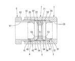
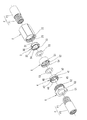
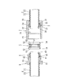
添付の図1〜図7は、この発明の一実施の形態を示す。この実施の形態のフレキシブル管用継手1は、図2に示すように、金属製の蛇腹管F1と樹脂製の被覆管F2とからなる二つのフレキシブル(第1及び第2フレキシブル管)管F,Fを互いに接続するためのものである。継手1は、図1〜図3に示すように、継手本体2、第1及び第2係合部材3,4、当接部材5及び押圧部材6を主な構成要素としている。
The best mode for carrying out the present invention will be described below with reference to the drawings.
1 to 7 of the accompanying drawings show an embodiment of the present invention. As shown in FIG. 2, the
継手本体2は、筒状をなしており、その内部が断面円形の接続孔21になっている。継手本体2は、接続孔21を有する限り筒状に形成する必要がなく、任意の形状を採用することができる。接続孔21は、その全長の大部分を占める大径孔部22と、その一端部(図1において右端部;以下、左右は図1における左右を意味するものとする。)に形成された小径孔部23とから構成されている。大径孔部22と小径孔部23とは、同軸に配置されている。図2に示すように、大径孔部22の内径は、フレキシブル管Fの外径(被覆管F2の外径)より所定の寸法だけ大きい寸法に設定されている。小径孔部23の内径は、被覆管F2を小径孔部23に挿入することができるよう、被覆管F2の外径と同等か僅かに大径に設定されている。
The
大径孔部22と小径孔部23との間には、段差面(停止部)24が環状に形成されている。段差面24は、接続孔21の軸線と直交する平面によって構成されているが、第1係合部材3の右方への移動を阻止するものである限り、平面以外の他の面によって構成してもよい。大径孔部22の内周面の左端部には、雌ねじ孔部25が形成されている。
A step surface (stop portion) 24 is formed in an annular shape between the large
接続孔21内には、第1係合部材3が接続孔21の軸線方向へ移動可能に挿入されている。第1係合部材3は、金属製の円筒体からなるものであり、図1〜図3に示すように、第1係合部材3の外周面には、その右側に小径部31が形成され、左側に大径部32が形成されている。小径部31と大径部32とは、同軸に配置されている。小径部31と大径部32との間には、当接面33が環状に形成されている。
The
小径部31は、小径孔部23の内径とほぼ同一の外径を有しており、小径孔部23の左端部に挿脱可能に挿入されている。当接面33は、段差面24に押し付けられている。当接面33が段差面24に押し付けられることにより、第1係合部材3の右方への移動が阻止されている。大径部32は、大径孔部22の内部の右端部に挿入されている。大径部32の外径は、大径孔部22の内径より所定の寸法だけ小径に設定されている。したがって、大径部32の外周面と大径孔部22の内周面との間には、環状に延びる隙間が形成されている。
The small-
第1係合部材3の内径は、フレキシブル管Fの蛇腹管F1の外径とほぼ同一寸法に設定されており、第1係合部材3の内部には、蛇腹管F1が挿通される。第1係合部材3の内周面の左端部には、係合突出部34が環状に形成されている。この係合突出部34の内径は、蛇腹管F1の外径より小径に設定されている。したがって、係合突出部34が蛇腹管F1の谷部に挿入されると、第1係合部材3とフレキシブル管Fとは、それらの軸線方向における係合突出部34と蛇腹管F1の谷部との寸法差の分を除き、一体に移動するように連結される。
The inner diameter of the
第1係合部材3には、二つのスリット35,36が形成されている。二つのスリット35,36は、第1係合部材3の周方向へ180°離れて配置されている。一方のスリット35は、第1係合部材3をその軸線方向へ縦断している。他方のスリット36は、大径部32の端面から小径部31の中途部まで延びている。したがって、スリット36の端部と小径部31の端面との間には、実質部が残っており、スリット35,36によって区分される第1係合部材3の二つの部分が、その実質部によって一体的に連結されている。実質部は、スリット35の幅が広狭に変化するように変形可能であり、そのように変形することによって、第1係合部材3が拡縮径可能になっている。第1係合部材3は、一方のフレキシブル管(図2において右側のフレキシブル管;以下、第1フレキシブル管という。)の蛇腹管F1がその軸線方向へ挿入可能になるまで拡径可能である。そして、拡径された第1係合部材3内に蛇腹管F1が挿入された後、第1係合部材3が縮径されることにより、係合突出部34が蛇腹管F1の谷部に係合させられている。係合突出部34は、蛇腹管F1の先端から1番目の山部と2番目の山部との間の谷部に係合させられているが、2番目と3番目の山部との間の谷部に係合させてもよく、あるいはそれより後方の谷部に係合させてもよい。
Two
第2係合部材4は、第1係合部材3と同一形状、同一寸法を有している。したがって、第2係合部材4は、第1係合部材3の小径部31、大径部32、当接面33、係合突出部34及びスリット35,36にそれぞれ対応した小径部41、大径部42、当接面43、係合突出部44及びスリット45,46を有している。
The
第2係合部材4は、大径孔部22内にその軸線方向へ移動可能に、かつ第1係合部材3から左方へ離間して配置されている。しかも、第2係合部材4は、第1係合部材3と左右対称に配置されている。つまり、小径部41が左側に位置し、大径部42が右側に位置するように配置されている。したがって、当接面43は、左方を向いている。
The
第2係合部材4の内部には、他方のフレキシブル管(図2において左側のフレキシブル管;以下、第2フレキシブル管という。)Fの蛇腹管F1が挿通されている。そして、係合突出部44が蛇腹管F1の谷部に係合されている。なお、第1フレキシブル管Fの蛇腹管F1の第2係合部材4への挿入、及び係合突出部44の蛇腹管F1への係合は、第1フレキシブル管Fの蛇腹管F1の第1係合部材3への挿入、及び係合突出部34の蛇腹管F1への係合と同様にして行うことができる。
A bellows tube F1 of the other flexible tube (left flexible tube in FIG. 2; hereinafter referred to as a second flexible tube) F is inserted into the
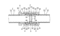
第1及び第2係合部材3,4間の大径孔部22内には、当接部材5が大径孔部22の軸線方向へ移動可能に挿入されている。当接部材5は、円筒状に形成されており、その外径は大径孔部22の内径とほぼ同一に設定されている。当接部材5の内周面の中央部には、環状突出部51が形成されている。環状突出部51の両端面には、環状凹部52,52がそれぞれ形成されている。各環状凹部52,52には、環状のパッキン(第1、第2当接部)53,53がそれぞれ装着されている。パッキン53の外径は、蛇腹管F1の最大外径より若干大径に設定されており、パッキン53の内径は、蛇腹管F1の最小内径より若干小径に設定されている。したがって、接続孔21内にその両端開口部から第1及び第2フレキシブル管F,Fがそれぞれ挿入されると、第1フレキシブル管Fの蛇腹管F1の先端部が右側のパッキン53に突き当たり、第2フレキシブル管Fの蛇腹管F2の先端部が左側のパッキン53に突き当たる。
The
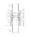
当接部材5の内周面の両端部には、当接部材5の軸線方向の外側から内側へ向かって小径になるテーパ孔部(第1及び第2縮径孔部)54,54がそれぞれ形成されている。テーパ孔部54の最大内径、つまりテーパ孔部54の外側の端縁のおける内径は、第1、第2係合部材3,4の大径部32,42の外径より若干大径に設定されている。したがって、右側のテーパ孔部54には、第1係合部材3の大径部32が挿入可能であり、左側のテーパ孔部54には、第2係合部材4の大径部42が挿入可能である。テーパ孔部54の最小内径、つまりテーパ孔部54の内側の端縁における内径は、大径部32,42の外径より小径に設定されている。したがって、大径部32,42がテーパ孔部54,54に所定距離以上挿入されると、大径部32,42がテーパ孔部54,54の内周面に押圧接触し、テーパ孔部54,54の内周面によって第1及び第2係合部材3,4が縮径される。これにより、第1及び第2係合部材3,4の係合突出部34,44が蛇腹管F1,F1の谷部から径方向外側に抜け出ることがないよう、谷部により確実に係合させられている。
Tapered hole portions (first and second reduced diameter hole portions) 54, 54 having a diameter that decreases from the outer side to the inner side in the axial direction of the
押圧部材6は筒状をなしており、その内部が貫通孔61とされている。貫通孔61の内径は、小径孔部21の内径と同一に設定されている。したがって、貫通孔61には、第2フレキシブル管Fの蛇腹管F1は勿論のこと、被覆管F2も挿入可能である。押圧部材6の外周面には、雄ねじ部62及びスパナ掛け部63が互いに同軸に形成されている。雄ねじ部62は、雌ねじ孔部25に螺合されている。スパナ掛け部63は、継手本体2から左外側に突出しており、スパナ掛け部63にスパナ(図示せず)を係合させてスパナ掛け部63を回転させることにより、雄ねじ部62を雌ねじ孔部25に対してねじ込み、ねじ外すことができる。
The
雄ねじ部62を雌ねじ孔部25にねじ込むと、押圧部材6が右方へ移動してその先端面が第2係合部材4の当接面43に突き当たる。したがって、押圧部材6をさらに右方へ移動させると、第2係合部材4及び第2フレキシブル管Fが右方へ移動させられ、蛇腹管F1の先端部が左側のパッキン(第2当接部)53に突き当たる。すると、当接部材5が、押圧部材6により第2係合部材4及び第2フレキシブル管Fを介して右方へ押され、それらと一緒に右方へ移動する。当接部材5が右方へ移動すると、右側のパッキン(第1当接部)53が第1フレキシブル管Fの蛇腹管F1の先端部に突き当たり、第1係合部材3が蛇腹管F1によって右方へ押される。このとき、第1係合部材3は、当接面33が段差面24に突き当たることによって右方への移動が阻止されている。したがって、押圧部材6をさらに右方へ移動させると、左右のフレキシブル管F,Fの蛇腹管F1,F1の各先端部がパッキン53,53に強く押し付けられる。この結果、蛇腹管F1,F1が継手1を介して接続されるとともに、当接部材5の内部を介して連通する。このようにして、フレキシブル管F,Fが互いに接続される。接続途中には、第1係合部材3の左側の端部及び第2係合部材4の右側の端部が、当接部材5の左右のテーパ孔部54,54にそれぞれ挿入される。その結果、第1及び第2当接部材3,4が縮径される。
When the
なお、蛇腹管F1,F1の先端側の一山が押し潰される前に押圧部材6のスパナ掛け部63が継手本体2の左端面に突き当たり、それによって押圧部材6の右方への移動が阻止されているので、蛇腹管F1,F1の先端部の山部は、半分ほど潰されるだけであり、完全に潰されることがない。しかし、スパナ掛け部63が継手本体2の左端面に突き当たる前に蛇腹管F1,F1の山部が完全に押し潰されるようにしてもよい。そのようにした場合には、蛇腹管F1,F1の先端部をパッキン53,53により一層強く押し付けることができる。
Note that the
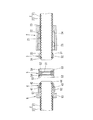
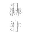
上記構成を有するフレキシブル管用継手1によって第1及び第2の二つのフレキシブル管F,Fを接続する場合の一例を説明する。まず、図4に示すように、第1フレキシブル管Fを小径孔部23にその右端開口部から挿入し、蛇腹管F1を接続孔21から左方へ突出させる。そして、蛇腹管F1の先端部の所定の位置に第1係合部材3を装着し、係合突出部34を蛇腹管F1の谷部に係合させる。一方、第2フレキシブル管Fについては、押圧部材6にその左端開口部から挿入し、蛇腹管F1を押圧部材6から右方へ突出させる。そして、右方へ突出した蛇腹管F1の先端部の所定の位置に第2係合部材4を装着し、係合突出部44を蛇腹管F1の谷部に係合させる。第2係合部材4の第2フレキシブル管Fへの装着後、押圧部材6を第2フレキシブル管Fに対して相対的に右方へ移動させ、押圧部材6の先端面を当接面43に押し付ける。
An example in which the first and second flexible pipes F and F are connected by the flexible pipe joint 1 having the above-described configuration will be described. First, as shown in FIG. 4, the first flexible tube F is inserted into the small
次に、図5に示すように、継手本体2を第1フレキシブル管Fに対して相対的に左方へ移動させ、段差面24を第1係合部材3の当接面33に押し付ける。その後、図6に示すように、当接部材5を接続孔21の大径孔部22にその左端開口部から挿入する。続いて、図7に示すように、第2フレキシブル管Fの蛇腹管F1及び第2係合部材4を接続孔21の大径孔部22にその左端開口部から挿入する。そして、押圧部材6の雄ねじ部62を雌ねじ孔部25に螺合させる。押圧部材6を所定の位置までねじ込むと、蛇腹管F1、F1の先端部がパッキン53,53にそれぞれ突き当たる。その後、スパナ掛け部63が継手本体2の左端面に突き当たるまで押圧部材6をさらにねじ込む。それにより、蛇腹管F1,F1の先端部の一山が半分ほど押し潰され、蛇腹管F1,F1の先端部がパッキン53,53にそれぞれ強く押し付けられる。これによって、フレキシブル管F,Fの接続が完了する。
Next, as shown in FIG. 5, the
上記ように、フレキシブル管用継手1を用いて二つのフレキシブル管F,Fを接続する場合には、一つの押圧部材6をねじ込むだけで足り、二つのナットをねじ込む必要がない。したがって、フレキシブル管F,Fの接続に要する手間を軽減することができる。
As described above, when connecting the two flexible pipes F and F using the flexible pipe joint 1, it is only necessary to screw one pressing
なお、この発明は、上記の実施の形態に限定されるものでなく、その要旨を逸脱しない範囲において各種の変形例を採用可能である。
例えば、上記の実施の形態においては、接続されるべき第1及び第2フレキシブル管F,Fが互いに同一寸法を有しているが、互いに異なる寸法を有する二つのフレキシブル管を接続するように構成することも可能である。その場合には、第1及び第2係合部材3,4及びパッキン53,53の各寸法が、二つのフレキシブル管の蛇腹管の寸法に対応して変えられる。
また、上記の実施の形態においては、第1係合部材3にスリット35,36を形成することよって第1係合部材3を拡縮径可能にしているが、コイルばねの両端部を連結してリング状に形成し、これを拡縮径可能な第1係合部材としてもよい。また、第1係合部材3は、全体としては一体に形成されているが、周方向に互いに分割された複数のセグメントによって第1係合部材を構成してもよい。第1係合部材3についてのこのような変形例は、第2係合部材4についても採用可能である。
さらに、上記の実施の形態においては、押圧部材6を継手本体2の内周面に形成された雌ねじ孔部25に螺合させているが、継手本体2の外周面に雄ねじ部を形成するとともに、押圧部材6の右端部を二重筒構造とし、その外筒部を雄ねじ部に螺合させる一方、内筒部を大径孔部22に挿入し、その内筒部によって第2係合部材4を押すようにしてもよい。
In addition, this invention is not limited to said embodiment, A various modification is employable in the range which does not deviate from the summary.
For example, in the above embodiment, the first and second flexible pipes F and F to be connected have the same dimensions, but are configured to connect two flexible pipes having different dimensions. It is also possible to do. In that case, each dimension of the 1st and 2nd engaging
In the above embodiment, the
Furthermore, in the above embodiment, the pressing
F フレキシブル管(第1、第2フレキシブル管)
F1 蛇腹管
1 フレキシブル管用継手
2 継手本体
3 第1係合部材
4 第2係合部材
5 当接部材
6 押圧部材
21 接続孔
24 段差面(停止部)
53 パッキン(第1、第2当接部)
54 テーパ孔部(第1、第2縮径孔部)
61 貫通孔
F Flexible pipe (first and second flexible pipes)
F1 bellows
53 Packing (first and second contact parts)
54 Tapered hole (first and second reduced diameter holes)
61 Through hole
Claims (2)
一端開口部及び他端開口部から上記第1及び第2フレキシブル管がそれぞれ挿入される接続孔を有し、上記接続孔の内周面に停止部が形成された継手本体と、上記接続孔にその一端開口部から挿入された上記第1フレキシブル管の蛇腹管の外周に係合され、上記停止部に突き当たることによって上記継手本体の他端側から一端側への移動が阻止されるとともに、同方向への上記第1フレキシブル管の移動を阻止する第1係合部材と、上記接続孔にその他端開口部から挿入された上記第2フレキシブル管の蛇腹管の外周に係合されるとともに、上記接続孔に移動可能に挿入された第2係合部材と、上記第1及び第2係合部材間の上記接続孔内に移動可能に挿入され、両端部に上記第1及び第2フレキシブル管の蛇腹管の先端部がそれぞれ突き当たる第1及び第2当接部が環状に形成された筒状の当接部材と、上記第2フレキシブル管が挿通される貫通孔を有し、上記継手本体の他端部に螺合され、上記第2フレキシブル管の蛇腹管を上記第2係合部材を介して上記継手本体の他端側から一端側へ押す押圧部材とを備え、
上記押圧部材が上記継手本体にねじ込まれると、上記第2フレキシブル管の蛇腹管が上記押圧部材により第2係合部材を介して上記継手本体の他端側から一端側へ押されて上記当接部材の上記第2当接部に押し付けられ、上記押圧部材が上記継手本体にさらにねじ込まれると、上記当接部材が上記押圧部材により上記第2係合部材及び上記第2フレキシブル管の蛇腹管を介して上記継手本体の一端側へ押圧移動させられて、上記第1当接部が上記第1フレキシブル管の蛇腹管の先端部に押し付けられ、それよって上記第1及び第2フレキシブル管の蛇腹管どうしが上記当接部材の内部を介して連通されることを特徴とするフレキシブル管用継手。 In the joint for flexible pipes for connecting the bellows pipes of the first and second flexible pipes,
A joint body having a connection hole into which the first and second flexible pipes are inserted from one end opening and the other end opening, respectively, and a stop formed on the inner peripheral surface of the connection hole; and the connection hole The joint body is engaged with the outer periphery of the bellows tube of the first flexible tube inserted from the one end opening portion, and the movement of the joint body from the other end side to the one end side is prevented by striking the stop portion. A first engaging member that prevents movement of the first flexible tube in a direction, and an outer periphery of the bellows tube of the second flexible tube inserted into the connection hole from the other end opening, and A second engagement member movably inserted into the connection hole, and movably inserted into the connection hole between the first and second engagement members, and the first and second flexible pipes at both ends. The tip of the bellows tube A cylindrical contact member in which the first and second contact portions are annularly formed, and a through hole through which the second flexible tube is inserted, and is screwed into the other end portion of the joint body, A pressing member that pushes the bellows tube of the second flexible tube from the other end side of the joint body to the one end side through the second engagement member;
When the pressing member is screwed into the joint main body, the bellows tube of the second flexible pipe is pushed from the other end side of the joint main body to the one end side by the pressing member via the second engagement member, and the contact is made. When pressed against the second contact portion of the member and the pressing member is further screwed into the joint body, the contact member causes the second engaging member and the bellows tube of the second flexible tube to be pressed by the pressing member. The first abutment portion is pressed against the distal end portion of the bellows tube of the first flexible tube, and thereby the bellows tubes of the first and second flexible tubes. A joint for flexible pipes, characterized in that they communicate with each other through the inside of the contact member.
Priority Applications (1)
| Application Number | Priority Date | Filing Date | Title |
|---|---|---|---|
| JP2013220946A JP2015081663A (en) | 2013-10-24 | 2013-10-24 | Fitting for flexible pipe |
Applications Claiming Priority (1)
| Application Number | Priority Date | Filing Date | Title |
|---|---|---|---|
| JP2013220946A JP2015081663A (en) | 2013-10-24 | 2013-10-24 | Fitting for flexible pipe |
Publications (1)
| Publication Number | Publication Date |
|---|---|
| JP2015081663A true JP2015081663A (en) | 2015-04-27 |
Family
ID=53012375
Family Applications (1)
| Application Number | Title | Priority Date | Filing Date |
|---|---|---|---|
| JP2013220946A Pending JP2015081663A (en) | 2013-10-24 | 2013-10-24 | Fitting for flexible pipe |
Country Status (1)
| Country | Link |
|---|---|
| JP (1) | JP2015081663A (en) |
Citations (6)
| Publication number | Priority date | Publication date | Assignee | Title |
|---|---|---|---|---|
| FR1244948A (en) * | 1959-09-21 | 1960-11-04 | Bergougnan Soc Gen Des Ets | Sophisticated connection for pipe elements |
| JPS4877413A (en) * | 1972-01-18 | 1973-10-18 | ||
| FR2230924A1 (en) * | 1973-05-21 | 1974-12-20 | Raoul Jean Jacques | Union for pipes of semi-rigid materials - nut forces sealing ring into reentrant cone formed by bush wrapped on pipe end |
| JPH0243590U (en) * | 1988-09-19 | 1990-03-26 | ||
| JPH09280432A (en) * | 1996-04-16 | 1997-10-31 | Yoshikuni Omote | Metal seal coupling |
| US5782500A (en) * | 1995-05-26 | 1998-07-21 | Mate; Robert James | Passageway aligned coupling and process |
-
2013
- 2013-10-24 JP JP2013220946A patent/JP2015081663A/en active Pending
Patent Citations (6)
| Publication number | Priority date | Publication date | Assignee | Title |
|---|---|---|---|---|
| FR1244948A (en) * | 1959-09-21 | 1960-11-04 | Bergougnan Soc Gen Des Ets | Sophisticated connection for pipe elements |
| JPS4877413A (en) * | 1972-01-18 | 1973-10-18 | ||
| FR2230924A1 (en) * | 1973-05-21 | 1974-12-20 | Raoul Jean Jacques | Union for pipes of semi-rigid materials - nut forces sealing ring into reentrant cone formed by bush wrapped on pipe end |
| JPH0243590U (en) * | 1988-09-19 | 1990-03-26 | ||
| US5782500A (en) * | 1995-05-26 | 1998-07-21 | Mate; Robert James | Passageway aligned coupling and process |
| JPH09280432A (en) * | 1996-04-16 | 1997-10-31 | Yoshikuni Omote | Metal seal coupling |
Similar Documents
| Publication | Publication Date | Title |
|---|---|---|
| JP4992098B2 (en) | Non-bolt joint structure and method for forming non-bolt joint structure | |
| WO2012128152A1 (en) | Pipe joint | |
| WO2014181591A1 (en) | Pipe connecting device | |
| JPH0571679A (en) | Tube coupling device | |
| US2951715A (en) | Tube coupling connection for plastic or soft metal tubing | |
| JP2011163533A (en) | Pipe joint | |
| JP5818855B2 (en) | Pipe fitting | |
| CN201034220Y (en) | Pipe joint system and pipe joint fitting | |
| JP2015081663A (en) | Fitting for flexible pipe | |
| JP2018184968A (en) | Pipeline connection structure | |
| JP4963688B2 (en) | Resin pipe fitting | |
| JP5055222B2 (en) | Resin pipe fitting | |
| JP7417931B2 (en) | Concrete member connection device | |
| TWI580844B (en) | And a connecting means for connecting the concrete members using the connecting means | |
| TWI586874B (en) | And a connecting means for connecting the concrete members using the connecting means | |
| JP6294986B1 (en) | Fitting for straight pipe | |
| CN207599188U (en) | Connecting pipe fast assembling-disassembling presss from both sides and fluid line connecting structure | |
| JP4751920B2 (en) | Resin pipe fitting | |
| JP2010038268A (en) | Resin pipe joint | |
| JP6654801B2 (en) | Pipe fittings | |
| JP5275839B2 (en) | Pipe fitting | |
| JP2015081609A (en) | Joint device | |
| JP2016211670A (en) | Mouthpiece | |
| JP7340847B2 (en) | Pipe fittings for resin pipes | |
| JP5865600B2 (en) | Pipe fitting |
Legal Events
| Date | Code | Title | Description |
|---|---|---|---|
| A621 | Written request for application examination |
Free format text: JAPANESE INTERMEDIATE CODE: A621 Effective date: 20160825 |
|
| A977 | Report on retrieval |
Free format text: JAPANESE INTERMEDIATE CODE: A971007 Effective date: 20170517 |
|
| A131 | Notification of reasons for refusal |
Free format text: JAPANESE INTERMEDIATE CODE: A131 Effective date: 20170523 |
|
| A02 | Decision of refusal |
Free format text: JAPANESE INTERMEDIATE CODE: A02 Effective date: 20171205 |