JP2014130881A - Polishing device - Google Patents
Polishing device Download PDFInfo
- Publication number
- JP2014130881A JP2014130881A JP2012287119A JP2012287119A JP2014130881A JP 2014130881 A JP2014130881 A JP 2014130881A JP 2012287119 A JP2012287119 A JP 2012287119A JP 2012287119 A JP2012287119 A JP 2012287119A JP 2014130881 A JP2014130881 A JP 2014130881A
- Authority
- JP
- Japan
- Prior art keywords
- gas
- pure water
- unit
- dissolved
- cleaning
- Prior art date
- Legal status (The legal status is an assumption and is not a legal conclusion. Google has not performed a legal analysis and makes no representation as to the accuracy of the status listed.)
- Pending
Links
Images


Classifications
-
- B—PERFORMING OPERATIONS; TRANSPORTING
- B24—GRINDING; POLISHING
- B24B—MACHINES, DEVICES, OR PROCESSES FOR GRINDING OR POLISHING; DRESSING OR CONDITIONING OF ABRADING SURFACES; FEEDING OF GRINDING, POLISHING, OR LAPPING AGENTS
- B24B37/00—Lapping machines or devices; Accessories
- B24B37/005—Control means for lapping machines or devices
-
- B—PERFORMING OPERATIONS; TRANSPORTING
- B24—GRINDING; POLISHING
- B24B—MACHINES, DEVICES, OR PROCESSES FOR GRINDING OR POLISHING; DRESSING OR CONDITIONING OF ABRADING SURFACES; FEEDING OF GRINDING, POLISHING, OR LAPPING AGENTS
- B24B1/00—Processes of grinding or polishing; Use of auxiliary equipment in connection with such processes
- B24B1/04—Processes of grinding or polishing; Use of auxiliary equipment in connection with such processes subjecting the grinding or polishing tools, the abrading or polishing medium or work to vibration, e.g. grinding with ultrasonic frequency
-
- B—PERFORMING OPERATIONS; TRANSPORTING
- B24—GRINDING; POLISHING
- B24B—MACHINES, DEVICES, OR PROCESSES FOR GRINDING OR POLISHING; DRESSING OR CONDITIONING OF ABRADING SURFACES; FEEDING OF GRINDING, POLISHING, OR LAPPING AGENTS
- B24B51/00—Arrangements for automatic control of a series of individual steps in grinding a workpiece
-
- B—PERFORMING OPERATIONS; TRANSPORTING
- B24—GRINDING; POLISHING
- B24B—MACHINES, DEVICES, OR PROCESSES FOR GRINDING OR POLISHING; DRESSING OR CONDITIONING OF ABRADING SURFACES; FEEDING OF GRINDING, POLISHING, OR LAPPING AGENTS
- B24B57/00—Devices for feeding, applying, grading or recovering grinding, polishing or lapping agents
Abstract
Description
本発明は、研磨装置に係り、特に半導体ウエハなどの基板の表面を、研磨装置の内部に配置される処理機能を備えた機構部等に付着した研磨液等のパーティクルによってディフェクトが発生することを防止しつつ、研磨して平坦化する研磨装置に関する。 The present invention relates to a polishing apparatus, and in particular, a defect occurs due to particles such as polishing liquid adhering to a mechanism unit having a processing function disposed inside a polishing apparatus on the surface of a substrate such as a semiconductor wafer. The present invention relates to a polishing apparatus that polishes and flattens while preventing.
半導体ウエハの表面を研磨する研磨装置は、一般に、研磨パッドからなる研磨面を有する研磨テーブルや、半導体ウエハを保持する研磨ヘッド(トップリング)等の種々の処理機能を備えた機構部を内部に備えている。そして、研磨ヘッドで保持した半導体ウエハを研磨パッドの研磨面に対して所定の圧力で押圧しつつ、研磨テーブルと研磨ヘッドとを相対運動させることにより、半導体ウエハを研磨面に摺接させて、半導体ウエハの表面を平坦かつ鏡面に研磨するようにしている。化学的機械研磨(CMP)にあっては、研磨時に、微粒子を含む研磨液(スラリー)が研磨面に供給される。研磨後の基板は、搬送ユニットによって、洗浄・乾燥ユニットに搬送され、この洗浄・乾燥ユニットで洗浄・乾燥された後、研磨装置から搬出される。 A polishing apparatus for polishing the surface of a semiconductor wafer generally includes a mechanism unit having various processing functions such as a polishing table having a polishing surface made of a polishing pad and a polishing head (top ring) for holding a semiconductor wafer. I have. Then, while pressing the semiconductor wafer held by the polishing head against the polishing surface of the polishing pad with a predetermined pressure, the semiconductor table is brought into sliding contact with the polishing surface by moving the polishing table and the polishing head relative to each other. The surface of the semiconductor wafer is polished to a flat and mirror surface. In chemical mechanical polishing (CMP), a polishing liquid (slurry) containing fine particles is supplied to the polishing surface during polishing. The substrate after polishing is transported to the cleaning / drying unit by the transport unit, cleaned and dried by the cleaning / drying unit, and then transported out of the polishing apparatus.
このように、研磨液を供給しながら半導体ウエハ等の基板の表面を研磨すると、研磨テーブルの研磨面には、研磨液や研磨かす等の多量のパーティクルが残留する。また、研磨時に研磨液が研磨テーブルの周辺に飛散し、研磨テーブルの周囲に配置されている処理機能を備えた機構部の表面に飛散した研磨液が付着する。更に、研磨後の基板を搬送する搬送ユニットや、研磨後の基板を洗浄する洗浄ユニットの洗浄具等にも研磨液が付着する。このように、研磨テーブルの研磨面に研磨液や研磨かす等が残留したり、研磨テーブルの周囲に配置されている処理機能を備えた機構部の表面や洗浄ユニットの洗浄具等に研磨液が付着したりすると、研磨後の基板にディフェクトを発生させる要因となる。 As described above, when the surface of the substrate such as a semiconductor wafer is polished while supplying the polishing liquid, a large amount of particles such as the polishing liquid and polishing residue remain on the polishing surface of the polishing table. Further, the polishing liquid scatters around the polishing table during polishing, and the splattered polishing liquid adheres to the surface of the mechanism unit having a processing function arranged around the polishing table. Further, the polishing liquid adheres to a transport unit that transports the polished substrate, a cleaning tool of a cleaning unit that cleans the polished substrate, and the like. As described above, the polishing liquid or polishing residue remains on the polishing surface of the polishing table, or the polishing liquid is applied to the surface of the mechanism unit having a processing function disposed around the polishing table or the cleaning tool of the cleaning unit. If it adheres, it causes a defect in the substrate after polishing.
一般に、研磨装置内部の所定位置には、種々の洗浄ユニットが配置されており、この洗浄ユニットの噴射口から研磨装置の所定の部位に向けて洗浄液を定期的に噴射することで、研磨テーブル及びその周辺に配置される各機構部等の表面に付着した研磨液を洗浄液で洗い流すことが広く行われている。この洗浄液として、研磨装置の内部に工場から供給される脱気された純水が一般に使用されている。 In general, various cleaning units are arranged at predetermined positions inside the polishing apparatus, and the cleaning table and the polishing table and the cleaning table and the cleaning unit are periodically sprayed from the injection port of the cleaning unit toward a predetermined portion of the polishing apparatus. It is widely practiced to wash away the polishing liquid adhering to the surface of each mechanism portion or the like disposed in the vicinity thereof with a cleaning liquid. As this cleaning liquid, deaerated pure water supplied from a factory into the polishing apparatus is generally used.
研磨装置内の洗浄機構として、研磨装置の内部に、キャビテーションを有する高圧水を利用して洗浄を行う超音波洗浄ユニットを搭載することが知られている。この超音波洗浄ユニットの高圧水として、工場から装置内に供給されて洗浄に使用される脱気された純水(洗浄液)が一般に使用されている。 As a cleaning mechanism in the polishing apparatus, it is known that an ultrasonic cleaning unit that performs cleaning using high-pressure water having cavitation is mounted inside the polishing apparatus. As the high-pressure water of this ultrasonic cleaning unit, deaerated pure water (cleaning liquid) that is supplied from the factory into the apparatus and used for cleaning is generally used.
工場から研磨装置に供給されて洗浄に使用される脱気された純水(洗浄液)は、極めて溶在気体を含まない状態になっている。例えば脱気された純水の溶存酸素量(DO値)は、通常10ppb以下であり、5ppb以下で管理されていることもある。最先端デバイスにおいては、溶存酸素量が1ppbの純水を洗浄等に使用することも要求されるようになってきている。 The degassed pure water (cleaning liquid) supplied from the factory to the polishing apparatus and used for cleaning is in a state that does not contain dissolved gas. For example, the dissolved oxygen content (DO value) of degassed pure water is usually 10 ppb or less and may be managed at 5 ppb or less. In state-of-the-art devices, it is also required to use pure water having a dissolved oxygen content of 1 ppb for cleaning and the like.
キャビテーションを利用した超音波洗浄は、溶在気体を含む液体に超音波を作用させることによる物理洗浄処理であり、超音波洗浄ユニットに供給される液体に要求される溶存気体の仕様例として、例えば「液体中に溶在気体量が例えばDO値にて1ppm〜15ppm」であることなどが挙げられる。また、気体を過剰に溶存させた液体を超音波洗浄に使用すると、十分な超音波洗浄特性が得られないことも知られている。 Ultrasonic cleaning using cavitation is a physical cleaning process by applying ultrasonic waves to a liquid containing dissolved gas. As a specification example of dissolved gas required for the liquid supplied to the ultrasonic cleaning unit, for example, “The amount of dissolved gas in the liquid is, for example, 1 ppm to 15 ppm in terms of DO value”. It is also known that when a liquid in which a gas is excessively dissolved is used for ultrasonic cleaning, sufficient ultrasonic cleaning characteristics cannot be obtained.
しかしながら、前述のように、例えばDO値を10ppb以下に脱気された純水を超音波洗浄に使用すると、純水中の溶在気体が極めて少なく、このため、十分な超音波洗浄特性を得ることが困難となる。すなわち、研磨装置のように、研磨液などでパーティクル汚染が懸念される装置内の洗浄処理において、脱気された純水を使用した超音波洗浄では、超音波洗浄本来の洗浄効果を十分に発揮できないと考えられる。 However, as described above, for example, when pure water deaerated to a DO value of 10 ppb or less is used for ultrasonic cleaning, the dissolved gas in the pure water is extremely small, and thus sufficient ultrasonic cleaning characteristics are obtained. It becomes difficult. In other words, ultrasonic cleaning using degassed pure water in a cleaning process in a device where there is a risk of particle contamination with a polishing liquid, such as a polishing device, exhibits the original cleaning effect of ultrasonic cleaning sufficiently. It is considered impossible.
本発明は、上記事情に鑑みてなされたもので、装置内の洗浄処理において、本来の洗浄効果を十分に発揮できる、最適な条件で超音波洗浄を行うことができるようにした研磨装置を提供することを目的とする。 The present invention has been made in view of the above circumstances, and provides a polishing apparatus capable of performing ultrasonic cleaning under optimum conditions that can sufficiently exhibit the original cleaning effect in the cleaning process in the apparatus. The purpose is to do.
本発明の研磨装置は、脱気された純水を装置内に供給する純水供給ラインと、前記純水供給ラインに接続され該純水供給ラインを通して供給される脱気された純水に気体を溶在させる気体溶在ユニットと、前記気体溶在ユニットに接続され該気体溶在ユニットで気体を溶在させた気体溶在純水を搬送する気体溶在純水搬送ラインと、前記気体溶在純水搬送ラインに接続され該気体溶在純水搬送ラインを通して搬送される気体溶在純水に超音波振動エネルギを与えて噴出させる超音波洗浄ユニットと、前記気体溶在ユニットと前記超音波洗浄ユニットを制御する制御部を有する。 A polishing apparatus according to the present invention includes a pure water supply line that supplies degassed pure water into the apparatus, and a gas that is connected to the pure water supply line and supplied through the pure water supply line. A gas-dissolved pure water transport line that transports gas-dissolved pure water in which gas is dissolved in the gas-dissolved unit. An ultrasonic cleaning unit that is connected to a pure water transport line and is jetted by applying ultrasonic vibration energy to the dissolved gas pure water transported through the dissolved gas pure water transport line; and the dissolved gas unit and the ultrasonic wave It has a control part which controls a washing unit.
これにより、気体溶在ユニットで純水に十分な量の気体を溶在させた気体溶在純水を生成し、この気体溶在純水に超音波振動エネルギを与えて超音波洗浄ユニットから噴出させることで、本来の洗浄効果を十分に発揮できる、最適な条件で超音波洗浄を行うことができる。 As a result, the gas-dissolved unit generates gas-dissolved pure water in which a sufficient amount of gas is dissolved in the pure water, and ultrasonic vibration energy is applied to the gas-dissolved pure water and ejected from the ultrasonic cleaning unit. By doing so, it is possible to perform ultrasonic cleaning under optimum conditions that can sufficiently exhibit the original cleaning effect.
本発明の好ましい一態様において、前記気体溶在純水搬送ラインから前記超音波洗浄ユニットに搬送される気体溶在純水の溶在気体量をモニタして前記制御部に送るセンサを更に有する。
これにより、気体溶在純水搬送ラインから超音波洗浄ユニットに搬送される気体溶在純水の溶在気体量をセンサで測定し、この測定値を基に気体溶在ユニットを制御することで、超音波洗浄ユニットに搬送される気体溶在純水の溶在気体量を所定の範囲内に制御することができる。
In a preferred aspect of the present invention, the apparatus further includes a sensor that monitors the dissolved gas amount of the gas-dissolved pure water transported from the gas-dissolved pure water transport line to the ultrasonic cleaning unit and sends it to the control unit.
Thus, by measuring the dissolved gas amount of gas-dissolved pure water transported from the gas-dissolved pure water transport line to the ultrasonic cleaning unit with a sensor, and controlling the gas-dissolved unit based on this measurement value, The dissolved gas amount of the gas-dissolved pure water conveyed to the ultrasonic cleaning unit can be controlled within a predetermined range.
本発明の好ましい一態様において、前記気体溶在純水搬送ラインから前記超音波洗浄ユニットに搬送される気体溶在純水の温度を調整する温度調整ユニットを更に有する。
装置内に供給される脱気された純水の温度は、一般に21℃〜25℃程度に制御されるが、気体溶在純水の温度を、例えば18°〜40℃程度まで温度調整ユニットで制御できるようにすることで、高い洗浄効果を得ることができる。
In a preferred aspect of the present invention, the apparatus further includes a temperature adjustment unit that adjusts the temperature of the gas-dissolved pure water transported from the gas-dissolved pure water transport line to the ultrasonic cleaning unit.
The temperature of the deaerated pure water supplied into the apparatus is generally controlled to about 21 ° C. to 25 ° C., but the temperature of the gas-dissolved pure water is set to, for example, about 18 ° C. to 40 ° C. with a temperature adjustment unit. By making it controllable, a high cleaning effect can be obtained.
本発明によれば、気体溶在ユニットで十分な量の気体を溶在させた気体溶在純水を生成し、この気体溶在純水に超音波振動エネルギを与えて超音波洗浄ユニットから噴出させることで、例えば装置内の研磨液等によるパーティクルが懸念される機構部に対して、本来の洗浄効果を十分に発揮できる、最適な条件で超音波洗浄を行うことができる。 According to the present invention, gas-dissolved pure water in which a sufficient amount of gas is dissolved is generated by the gas-dissolving unit, and ultrasonic vibration energy is applied to the gas-dissolved pure water and ejected from the ultrasonic cleaning unit. By doing so, for example, ultrasonic cleaning can be performed under optimum conditions that can sufficiently exhibit the original cleaning effect on a mechanism portion where particles due to polishing liquid or the like in the apparatus are concerned.
以下、本発明の実施形態について図面を参照して説明する。
図1は、本発明の実施形態の研磨装置全体の概要を示す平面図ある。図1に示すように、この研磨装置は、略矩形状のハウジング10を備えており、ハウジング10の内部は、ロード/アンロード部12及び処理部14に区画され、処理部14の内部に、処理機能を備えた機構部としての複数(図示では4つ)の研磨ユニット16a〜16d、搬送ユニット18及び洗浄・乾燥ユニット20が配置されている。複数の研磨ユニット16a〜16dは、研磨装置の長手方向に沿って配列されている。
Embodiments of the present invention will be described below with reference to the drawings.
FIG. 1 is a plan view showing an outline of the entire polishing apparatus according to the embodiment of the present invention. As shown in FIG. 1, the polishing apparatus includes a substantially
ロード/アンロード部12は、多数の半導体ウエハ等の基板をストックする基板カセットが載置されるフロントロード部22を備えている。このフロントロード部22は、ハウジング10に隣接して配置されている。フロントロード部22には、オープンカセット、SMIF(Standard Manufacturing Interface)ポッド、またはFOUP(Front Opening Unified Pod)を搭載することができる。ここで、SMIF、FOUPは、内部に基板カセットを収納し、隔壁で覆うことにより、外部空間とは独立した環境を保つことができる密閉容器である。
The load / unload unit 12 includes a
これにより、ロード、アンロード部12に配置された搬送ロボット(図示せず)は、フロントロード部22に搭載された基板カセットから1枚の基板を取り出して搬送ユニット18に搬送する。搬送ユニット18は、研磨ユニット16a〜16dのいずれかに一つに基板を搬送し、この研磨ユニット16a〜16dのいずれか一つで研磨された基板を受け取って、洗浄・乾燥ユニット20に搬送する。そして、洗浄・乾燥ユニット20で洗浄され乾燥された基板は、ロード、アンロード部12の搬送ロボットによって、フロントロード部22に搭載された基板カセットに戻される。
Thereby, a transfer robot (not shown) arranged in the load / unload unit 12 takes out one substrate from the substrate cassette mounted on the
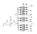
ハウジング10の内部には、例えばDO値が10ppb以下に脱気された純水を工場から研磨装置に供給する純水供給ライン30が延びている。そして、純水供給ライン30には、例えば透過膜またはバブリングによって、純水中に気体を溶在させて気体溶在量を増加させた気体溶在純水を生成する気体溶在ユニット32が接続されている。この気体溶在ユニット32で生成される気体溶在純水の溶在気体量は、DO値で、一般には1〜15ppm、例えば3〜8ppmである。これにより、気体溶在ユニット32で純水に十分な量の気体を溶在させた気体溶在純水を生成し、この気体溶在純水に超音波振動エネルギを与えて下記の各超音波洗浄ユニット40a〜40d、42a,42b、44a〜44cから噴出させることで、本来の洗浄効果を十分に発揮できる、最適な条件で超音波洗浄を行うことができる。
A pure
この純水中に溶存させる気体としては、例えば、N2ガスやアルゴンガス等の不活性ガスが好ましく使用される。クリーンルーム環境の大気中などの気体(酸素)も、研磨装置の洗浄に影響がなければ使用できる。また、炭酸ガスや水素などの気体を使用し、純水に炭酸ガスや水素などの気体を溶在させた炭酸ガス水や水素水等の機能水を気体溶在純水として使用してもよい。 As the gas dissolved in the pure water, for example, an inert gas such as N 2 gas or argon gas is preferably used. A gas (oxygen) such as the air in a clean room environment can be used as long as it does not affect the cleaning of the polishing apparatus. Moreover, carbon dioxide gas, hydrogen, or other gases may be used, and functional water such as carbon dioxide water or hydrogen water in which gases such as carbon dioxide or hydrogen are dissolved in pure water may be used as the gas-dissolved pure water. .
気体溶在ユニット32には、気体溶在ユニット32で生成された気体溶在純水を搬送する気体溶在純水搬送ライン34が接続され、この気体溶在純水搬送ライン34には、気体溶在純水搬送ライン34に沿って流れる気体溶在純水の溶在気体量を測定するセンサ36と、気体溶在純水搬送ライン34に沿って流れる気体溶在純水の温度を調整する温度調整ユニット38が設置されている。
The gas-dissolved pure
この例では、図2に示すように、研磨ユニット14dに4つの超音波洗浄ユニット40a〜40dが、搬送ユニット18に2つの超音波洗浄ユニット42a,42bが、洗浄・乾燥ユニット20に3つの超音波洗浄ユニット44a〜44cがそれぞれ備えられている。なお、図示しないが、他の研磨ユニット14a〜14cにも、研磨ユニット14dと同様に4つの超音波洗浄ユニットが備えられている。そして、気体溶在純水搬送ライン34は、温度調整ユニット38の下流側で複数に複数の分岐ライン46に分岐し、この各分岐ライン50の先端に超音波洗浄ユニット40a〜40d、42a,42b、44a〜44cがそれぞれ接続されている。
In this example, as shown in FIG. 2, four
超音波洗浄ユニット40aは、図3に示すように、本体50の内部の流体流路52に、超音波振動子としての圧電素子54を配置して構成されている。これにより、圧電素子54を起動し、注入口52aから高圧の気体溶在純水を注入することにより、この気体溶在純水には超音波振動エネルギが付与され、この超音波振動エネルギを付与された気体溶在純水が噴射口52bから噴射される。
As shown in FIG. 3, the
なお、他の超音波洗浄ユニット40b〜40d、42a,42b、44a〜44cも、超音波洗浄ユニット40aと同様な構成を有している。
The other
更に、気体溶在ユニット32,温度調整ユニット38及び各超音波洗浄ユニット40a〜40d、42a,42b、44a〜44cを制御する制御部56が備えられている。そして、センサ36からの信号は、制御部56に入力される。
Furthermore, the
これにより、気体溶在純水搬送ライン34に沿って流れて各超音波洗浄ユニット40a〜40d、42a,42b、44a〜44cに搬送される気体溶在純水の溶在気体量をセンサ36で測定し、この測定値を基に気体溶在ユニット32を制御することで、各超音波洗浄ユニット40a〜40d、42a,42b、44a〜44cに搬送されて噴出される気体溶在純水の溶在気体量を所定の範囲内に制御することができる。
Thereby, the
図4は、溶在気体量をDO値で1.0ppm以下(DO値≦1.0ppm)とした気体溶在純水を使用して超音波洗浄を行った時に洗浄後に残る100nm以上のディフェクト数を測定した結果を実施例1として、溶在気体量をDO値で1.5ppm以上(DO値≧1.5ppm)とした気体溶在純水を使用して超音波洗浄を行った時に洗浄後に残る100nm以上のディフェクト数を測定した結果を実施例2として示している。図4では、DO値で1.0ppb以下(DO値≦1.0ppb)の脱気された純水を使用して超音波洗浄を行った時に洗浄後に残る100nm以上のディフェクト数を測定した結果を比較例1として示している。なお、図4においては、ディフェクト数を比較例1のディフェクト率を100%とした百分率(ディフェクト率)で示している。 FIG. 4 shows the number of defects of 100 nm or more remaining after cleaning when ultrasonic cleaning is performed using gas-dissolved pure water whose DO value is 1.0 ppm or less (DO value ≦ 1.0 ppm). As a result of measuring the amount of dissolved gas as a first example, after ultrasonic cleaning using gas-dissolved pure water having a dissolved gas amount of 1.5 ppm or more (DO value ≧ 1.5 ppm) in DO value, after cleaning The result of measuring the number of remaining defects of 100 nm or more is shown as Example 2. FIG. 4 shows the results of measuring the number of defects of 100 nm or more remaining after cleaning when ultrasonic cleaning was performed using degassed pure water having a DO value of 1.0 ppb or less (DO value ≦ 1.0 ppb). This is shown as Comparative Example 1. In FIG. 4, the number of defects is shown as a percentage (defect rate) with the defect rate of Comparative Example 1 being 100%.
この図4から、溶在気体量をDO値で1.0ppm以下(DO値≦1.0ppm)、更には1.5ppm以上(DO値≧1.5ppm)とした気体溶在純水を使用して超音波洗浄を行うことで、DO値で1.0ppb以下(DO値≦1.0ppb)に脱気された純水を使用して超音波洗浄を行った場合に比較して、洗浄後に残る100nm以上のディフェクト数を削減でき、特にDO値を1.5ppm以上に上げることで、この削減効果が顕著になることが判る。 From FIG. 4, the use of gas-dissolved pure water having a dissolved gas amount of 1.0 ppm or less (DO value ≦ 1.0 ppm) and further 1.5 ppm or more (DO value ≧ 1.5 ppm) in terms of DO value is used. As a result of ultrasonic cleaning, it remains after cleaning compared to when ultrasonic cleaning is performed using pure water deaerated to a DO value of 1.0 ppb or less (DO value ≦ 1.0 ppb). It can be seen that the number of defects of 100 nm or more can be reduced, and in particular, this reduction effect becomes remarkable by increasing the DO value to 1.5 ppm or more.
純水供給ライン30から供給される純水の温度は、一般に21℃〜25℃程度に制御されている。超音波洗浄においては、ある程度高い温度の液体を噴出ことで、高い超音波洗浄特性が得られることがある。このため、この例では、気体溶在純水搬送ライン34に沿って流れて各超音波洗浄ユニット40a〜40d、42a,42b、44a〜44cに搬送される気体溶在純水の温度を、温度調整ユニット38で18°〜40℃程度まで制御できるようにしている。
The temperature of pure water supplied from the pure
このように、この例では、気体溶在純水中に溶在する溶存気体量と気体溶在純水の温度とを、超音波洗浄特性を最適化するパラメーターとして使用し、これらの値を制御できるようにしている。 Thus, in this example, the amount of dissolved gas dissolved in the gas-dissolved pure water and the temperature of the gas-dissolved pure water are used as parameters for optimizing the ultrasonic cleaning characteristics, and these values are controlled. I can do it.
なお、各超音波洗浄ユニット40a〜40d、42a,42b、44a〜44cにあっては、圧電素子54の周波数(数百Hz〜1MHz程度)及び動力(パワー)等が制御部56で制御される。
In each of the
図5は、研磨ユニット14dと研磨ユニット14dに備えられて超音波洗浄に使用される超音波洗浄ユニット40a〜40cの関係を示す。この例において、超音波洗浄ユニット40aは、研磨ユニット14dの研磨ヘッド60の下面で保持した基板(図示せず)を水ポリッシングする時の研磨パッド62の洗浄に使用される。つまり、この水ポリッシング時に、超音波洗浄ユニット40aから超音波振動エネルギを与えた気体溶在純水を研磨パッド62に向けて噴出することで、研磨パッド62が洗浄される。超音波洗浄ユニット40bは、研磨パッド62をドレッサ64でドレッシング(目立て)する時の研磨パッド62の洗浄に使用される。つまり、このドレッシング時に、超音波洗浄ユニット40bから超音波振動エネルギを与えた気体溶在純水を研磨ヘッド62に向けて噴出することで、研磨パッド62が洗浄される。超音波洗浄ユニット40cは、研磨パッド62をアトマイザ処理する時の研磨パッド62の洗浄に使用される。つまり、このアトマイザ処理時に、アトマイザ66に取付けた超音波洗浄ユニット40cから超音波振動エネルギを与えた気体溶在純水を研磨ヘッド62に向けて噴出することで、研磨パッド62が洗浄される。
FIG. 5 shows the relationship between the polishing
なお、図5には図示しないが、図1及び図2に示す超音波洗浄ユニット40dは、ドレッサ64を洗浄する洗浄位置に配置され、ドレッサ64の洗浄し使用される。つまり、ドレッサ64の洗浄時に、超音波洗浄ユニット40dから超音波振動エネルギを与えた気体溶在純水をドレッサ64の摺接部に向けて噴出することで、ドレッサ64が洗浄される。
なお、図示しないが、他の研磨ユニット14a〜14cにも、研磨ユニット14dと同様な構成が備えられている。
Although not shown in FIG. 5, the
Although not shown, the other polishing units 14a to 14c have the same configuration as the
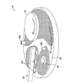
図6及び図7は、搬送ユニット18に基板を受け渡した後の研磨ヘッド60と、搬送ユニット18に備えられて超音波洗浄に使用される超音波洗浄ユニット42a,42bの関係を示す。この例において、超音波洗浄ユニット42aは、研磨ヘッド60の底面に設けられて基板を吸着保持するメンブレン68の洗浄に使用される。つまり、基板を搬送ユニット18に受け渡した研磨ヘッド60のメンブレン68に向けて、超音波洗浄ユニット42aから超音波振動エネルギを与えた気体溶在純水を噴出することで、研磨ヘッド60のメンブレン68が洗浄される。超音波洗浄ユニット42bは、研磨ヘッド60の底面のメンブレン68とその外周のリテーナリング70との隙間に生じる隙間の洗浄に使用される。つまり、基板を搬送ユニット18に受け渡した研磨ヘッド60の底面のメンブレン68とその外周のリテーナリング70との隙間に向けて、超音波洗浄ユニット42bから超音波振動エネルギを与えた気体溶在純水を噴出することで、底面のメンブレン68とその外周のリテーナリング70との隙間が洗浄される。
6 and 7 show the relationship between the polishing
図8は、洗浄・乾燥ユニット20と洗浄・乾燥ユニット20に備えられて超音波洗浄に使用される超音波洗浄ユニット44aの関係を示す。この例において、超音波洗浄ユニット44aは、洗浄・乾燥研磨ユニット20のロール洗浄部材72の洗浄に使用される。つまり、このロール洗浄部材72の洗浄時に、超音波洗浄ユニット44aから超音波振動エネルギを与えた気体溶在純水を、ロール洗浄部材72と洗浄板74との摺接部に向けて噴出することで、ロール洗浄部材72が洗浄される。
FIG. 8 shows the relationship between the cleaning / drying
図8は、洗浄・乾燥ユニット20と洗浄・乾燥ユニット20に備えられて超音波洗浄に使用される他の超音波洗浄ユニット44bの関係を示す。この例において、超音波洗浄ユニット44bは、洗浄・乾燥研磨ユニット20のペンシル型洗浄部材76の洗浄に使用される。つまり、このペンシル型洗浄部材76の洗浄時に、超音波洗浄ユニット44bから超音波振動エネルギを与えた気体溶在純水を、ペンシル型洗浄部材76と洗浄板88との摺接部に向けて噴出することで、ペンシル型洗浄部材76が洗浄される。
FIG. 8 shows the relationship between the cleaning / drying
なお、図8及び図9には図示しないが、図2に示す超音波洗浄ユニット44cは、洗浄・乾燥ユニット20のロール洗浄部材を回転させるロール回転機構部を洗浄する洗浄位置に配置され、このロール回転機構部の洗浄に使用される。つまり、このロール回転機構部の洗浄時に、超音波洗浄ユニット44cから超音波振動エネルギを与えた気体溶在純水をロール回転機構部に向けて噴出することで、ロール回転機構部が洗浄される。
Although not shown in FIGS. 8 and 9, the
本発明によれば、気体溶在ユニットで十分な量の気体を溶在させた気体溶在純水を生成し、この気体溶在純水に超音波振動エネルギを与えて超音波洗浄ユニットから噴出させることで、例えば装置内の研磨液等によるパーティクルが懸念される機構部に対して、本来の洗浄効果を十分に発揮できる、最適な条件で超音波洗浄を行うことができる。 According to the present invention, gas-dissolved pure water in which a sufficient amount of gas is dissolved is generated by the gas-dissolving unit, and ultrasonic vibration energy is applied to the gas-dissolved pure water and ejected from the ultrasonic cleaning unit. By doing so, for example, ultrasonic cleaning can be performed under optimum conditions that can sufficiently exhibit the original cleaning effect on a mechanism portion where particles due to polishing liquid or the like in the apparatus are concerned.
これまで本発明の一実施形態について説明したが、本発明は上述の実施形態に限定されず、その技術的思想の範囲内において種々異なる形態にて実施されてよいことは言うまでもない。 Although one embodiment of the present invention has been described so far, it is needless to say that the present invention is not limited to the above-described embodiment, and may be implemented in various forms within the scope of the technical idea.
10 ハウジング
16a〜16d 研磨ユニット
18 搬送ユニット
20 洗浄・乾燥ユニット
30 純水供給ライン
32 気体溶在ユニット
34 気体溶在純水搬送ライン
36 センサ
38 温度調整ユニット
40a〜40d,42,42b,44a〜44c 超音波洗浄ユニット
52 流体流路
52b 噴射口
54 圧電素子
56 制御部
60 研磨ヘッド
62 研磨パッド
64 ドレッサ
66 アトマイザ
68 メンブレン
70 リテーナリング
72 ロール洗浄部材
76 ペンシル型洗浄部材
DESCRIPTION OF
Claims (3)
前記純水供給ラインに接続され該純水供給ラインを通して供給される脱気された純水に気体を溶在させる気体溶在ユニットと、
前記気体溶在ユニットに接続され該気体溶在ユニットで気体を溶在させた気体溶在純水を搬送する気体溶在純水搬送ラインと、
前記気体溶在純水搬送ラインに接続され該気体溶在純水搬送ラインを通して搬送される気体溶在純水に超音波振動エネルギを与えて噴出させる超音波洗浄ユニットと、
前記気体溶在ユニットと前記超音波洗浄ユニットを制御する制御部を有することを特徴とする研磨装置。 A pure water supply line for supplying degassed pure water into the apparatus;
A gas dissolving unit that is connected to the pure water supply line and dissolves gas in the degassed pure water supplied through the pure water supply line;
A gas-dissolved pure water transport line that transports gas-dissolved pure water that is connected to the gas-dissolved unit and has dissolved gas in the gas-dissolved unit;
An ultrasonic cleaning unit that is connected to the gas-dissolved pure water transport line and jets by giving ultrasonic vibration energy to the gas-dissolved pure water transported through the gas-dissolved pure water transport line;
A polishing apparatus comprising a control unit for controlling the gas dissolving unit and the ultrasonic cleaning unit.
Priority Applications (4)
| Application Number | Priority Date | Filing Date | Title |
|---|---|---|---|
| JP2012287119A JP2014130881A (en) | 2012-12-28 | 2012-12-28 | Polishing device |
| KR1020130157709A KR101604519B1 (en) | 2012-12-28 | 2013-12-18 | Polishing apparatus |
| US14/139,764 US9162337B2 (en) | 2012-12-28 | 2013-12-23 | Polishing apparatus |
| TW102147895A TWI564112B (en) | 2012-12-28 | 2013-12-24 | Polishing apparatus |
Applications Claiming Priority (1)
| Application Number | Priority Date | Filing Date | Title |
|---|---|---|---|
| JP2012287119A JP2014130881A (en) | 2012-12-28 | 2012-12-28 | Polishing device |
Publications (2)
| Publication Number | Publication Date |
|---|---|
| JP2014130881A true JP2014130881A (en) | 2014-07-10 |
| JP2014130881A5 JP2014130881A5 (en) | 2015-12-03 |
Family
ID=51017685
Family Applications (1)
| Application Number | Title | Priority Date | Filing Date |
|---|---|---|---|
| JP2012287119A Pending JP2014130881A (en) | 2012-12-28 | 2012-12-28 | Polishing device |
Country Status (4)
| Country | Link |
|---|---|
| US (1) | US9162337B2 (en) |
| JP (1) | JP2014130881A (en) |
| KR (1) | KR101604519B1 (en) |
| TW (1) | TWI564112B (en) |
Cited By (3)
| Publication number | Priority date | Publication date | Assignee | Title |
|---|---|---|---|---|
| JP2016049612A (en) * | 2014-09-01 | 2016-04-11 | 株式会社荏原製作所 | Polishing method, and polishing device |
| CN108818278A (en) * | 2018-06-25 | 2018-11-16 | 浙江铁流离合器股份有限公司 | A kind of adjustable type clutch friction plate burnishing device of mechanical linkage type |
| CN111975471A (en) * | 2020-08-19 | 2020-11-24 | 蚌埠知博自动化技术开发有限公司 | Ultrasonic surface strengthening treatment equipment for surface treatment of metal material |
Families Citing this family (12)
| Publication number | Priority date | Publication date | Assignee | Title |
|---|---|---|---|---|
| US10058975B2 (en) | 2016-02-12 | 2018-08-28 | Applied Materials, Inc. | In-situ temperature control during chemical mechanical polishing with a condensed gas |
| US9962805B2 (en) * | 2016-04-22 | 2018-05-08 | Taiwan Semiconductor Manufacturing Company, Ltd. | Chemical mechanical polishing apparatus and method |
| JP6920849B2 (en) * | 2017-03-27 | 2021-08-18 | 株式会社荏原製作所 | Substrate processing method and equipment |
| US20200001426A1 (en) | 2018-06-27 | 2020-01-02 | Hari Soundararajan | Temperature Control of Chemical Mechanical Polishing |
| US11628478B2 (en) | 2019-05-29 | 2023-04-18 | Applied Materials, Inc. | Steam cleaning of CMP components |
| US11633833B2 (en) | 2019-05-29 | 2023-04-25 | Applied Materials, Inc. | Use of steam for pre-heating of CMP components |
| TW202110575A (en) | 2019-05-29 | 2021-03-16 | 美商應用材料股份有限公司 | Steam treatment stations for chemical mechanical polishing system |
| US11897079B2 (en) | 2019-08-13 | 2024-02-13 | Applied Materials, Inc. | Low-temperature metal CMP for minimizing dishing and corrosion, and improving pad asperity |
| KR20220116324A (en) | 2020-06-29 | 2022-08-22 | 어플라이드 머티어리얼스, 인코포레이티드 | Control of Steam Generation for Chemical Mechanical Polishing |
| CN115103738A (en) | 2020-06-29 | 2022-09-23 | 应用材料公司 | Temperature and slurry flow rate control in CMP |
| JP2023530555A (en) | 2020-06-30 | 2023-07-19 | アプライド マテリアルズ インコーポレイテッド | Apparatus and method for CMP temperature control |
| US11577358B2 (en) | 2020-06-30 | 2023-02-14 | Applied Materials, Inc. | Gas entrainment during jetting of fluid for temperature control in chemical mechanical polishing |
Citations (8)
| Publication number | Priority date | Publication date | Assignee | Title |
|---|---|---|---|---|
| JPH08255774A (en) * | 1995-03-16 | 1996-10-01 | Sony Corp | Chemical-mechanical polishing method and chemical-mechanical polishing apparatus |
| JPH10323631A (en) * | 1997-05-23 | 1998-12-08 | Ebara Corp | Device for self-cleaning cleaning member |
| JPH1199382A (en) * | 1997-09-29 | 1999-04-13 | Fron Tec:Kk | Pure water supply system and cleaner |
| JP2001015466A (en) * | 1999-06-16 | 2001-01-19 | Samsung Electronics Co Ltd | Chemical mechanical polishing apparatus and method for cleaning away contaminant in polishing head |
| JP2004296463A (en) * | 2003-03-25 | 2004-10-21 | Mitsubishi Electric Corp | Cleaning method and cleaning device |
| JP2005012238A (en) * | 2004-09-02 | 2005-01-13 | Ebara Corp | Method and apparatus for cleaning substrate |
| JP2006272549A (en) * | 1999-05-17 | 2006-10-12 | Ebara Corp | Dressing device |
| JP2008302478A (en) * | 2007-06-08 | 2008-12-18 | Tokyo Seimitsu Co Ltd | Washing device and method of polishing head |
Family Cites Families (25)
| Publication number | Priority date | Publication date | Assignee | Title |
|---|---|---|---|---|
| US5607718A (en) | 1993-03-26 | 1997-03-04 | Kabushiki Kaisha Toshiba | Polishing method and polishing apparatus |
| US5384989A (en) | 1993-04-12 | 1995-01-31 | Shibano; Yoshihide | Method of ultrasonically grinding workpiece |
| US5885134A (en) * | 1996-04-18 | 1999-03-23 | Ebara Corporation | Polishing apparatus |
| JP3696690B2 (en) * | 1996-04-23 | 2005-09-21 | 不二越機械工業株式会社 | Wafer polisher system |
| US5888124A (en) * | 1997-09-26 | 1999-03-30 | Vanguard International Semiconductor Corporation | Apparatus for polishing and cleaning a wafer |
| US6227944B1 (en) * | 1999-03-25 | 2001-05-08 | Memc Electronics Materials, Inc. | Method for processing a semiconductor wafer |
| US6358119B1 (en) * | 1999-06-21 | 2002-03-19 | Taiwan Semiconductor Manufacturing Company | Way to remove CU line damage after CU CMP |
| JP2001038614A (en) * | 1999-07-26 | 2001-02-13 | Ebara Corp | Grinding device |
| JP2001113455A (en) * | 1999-10-14 | 2001-04-24 | Sony Corp | Chemical mechanical polishing device and method |
| JP2002052370A (en) * | 2000-08-09 | 2002-02-19 | Ebara Corp | Substrate cleaning apparatus |
| US6811805B2 (en) * | 2001-05-30 | 2004-11-02 | Novatis Ag | Method for applying a coating |
| JP2004273961A (en) * | 2003-03-12 | 2004-09-30 | Ebara Corp | Cleaning device of metal wiring forming substrate |
| US7238085B2 (en) * | 2003-06-06 | 2007-07-03 | P.C.T. Systems, Inc. | Method and apparatus to process substrates with megasonic energy |
| CN1849182A (en) * | 2003-06-11 | 2006-10-18 | 艾奎昂技术股份有限公司 | Megasonic cleaning using supersaturated cleaning solution |
| TWI340060B (en) * | 2003-11-20 | 2011-04-11 | Doi Toshiro | Polishing apparatus and method of polishing work piece |
| TWI352645B (en) * | 2004-05-28 | 2011-11-21 | Ebara Corp | Apparatus for inspecting and polishing substrate r |
| JP2007290111A (en) * | 2006-03-29 | 2007-11-08 | Ebara Corp | Polishing method and polishing device |
| US7913705B2 (en) * | 2007-02-07 | 2011-03-29 | Tbw Industries, Inc. | Cleaning cup system for chemical mechanical planarization apparatus |
| SG148960A1 (en) * | 2007-06-15 | 2009-01-29 | Tokyo Electron Ltd | Substrate cleaning method and substrate cleaning apparatus |
| JP5365522B2 (en) * | 2008-07-03 | 2013-12-11 | 旭硝子株式会社 | Glass substrate polishing method and manufacturing method |
| JP4532580B2 (en) * | 2008-08-20 | 2010-08-25 | 株式会社カイジョー | Ultrasonic cleaning equipment |
| JP2010234298A (en) * | 2009-03-31 | 2010-10-21 | Kurita Water Ind Ltd | Device for supplying water containing dissolved gas and method for producing water containing dissolved gas |
| US20100291841A1 (en) * | 2009-05-14 | 2010-11-18 | Chien-Min Sung | Methods and Systems for Water Jet Assisted CMP Processing |
| JP5585076B2 (en) * | 2009-12-24 | 2014-09-10 | 栗田工業株式会社 | Cleaning method |
| JP5866227B2 (en) * | 2012-02-23 | 2016-02-17 | 株式会社荏原製作所 | Substrate cleaning method |
-
2012
- 2012-12-28 JP JP2012287119A patent/JP2014130881A/en active Pending
-
2013
- 2013-12-18 KR KR1020130157709A patent/KR101604519B1/en active IP Right Grant
- 2013-12-23 US US14/139,764 patent/US9162337B2/en active Active
- 2013-12-24 TW TW102147895A patent/TWI564112B/en active
Patent Citations (8)
| Publication number | Priority date | Publication date | Assignee | Title |
|---|---|---|---|---|
| JPH08255774A (en) * | 1995-03-16 | 1996-10-01 | Sony Corp | Chemical-mechanical polishing method and chemical-mechanical polishing apparatus |
| JPH10323631A (en) * | 1997-05-23 | 1998-12-08 | Ebara Corp | Device for self-cleaning cleaning member |
| JPH1199382A (en) * | 1997-09-29 | 1999-04-13 | Fron Tec:Kk | Pure water supply system and cleaner |
| JP2006272549A (en) * | 1999-05-17 | 2006-10-12 | Ebara Corp | Dressing device |
| JP2001015466A (en) * | 1999-06-16 | 2001-01-19 | Samsung Electronics Co Ltd | Chemical mechanical polishing apparatus and method for cleaning away contaminant in polishing head |
| JP2004296463A (en) * | 2003-03-25 | 2004-10-21 | Mitsubishi Electric Corp | Cleaning method and cleaning device |
| JP2005012238A (en) * | 2004-09-02 | 2005-01-13 | Ebara Corp | Method and apparatus for cleaning substrate |
| JP2008302478A (en) * | 2007-06-08 | 2008-12-18 | Tokyo Seimitsu Co Ltd | Washing device and method of polishing head |
Cited By (3)
| Publication number | Priority date | Publication date | Assignee | Title |
|---|---|---|---|---|
| JP2016049612A (en) * | 2014-09-01 | 2016-04-11 | 株式会社荏原製作所 | Polishing method, and polishing device |
| CN108818278A (en) * | 2018-06-25 | 2018-11-16 | 浙江铁流离合器股份有限公司 | A kind of adjustable type clutch friction plate burnishing device of mechanical linkage type |
| CN111975471A (en) * | 2020-08-19 | 2020-11-24 | 蚌埠知博自动化技术开发有限公司 | Ultrasonic surface strengthening treatment equipment for surface treatment of metal material |
Also Published As
| Publication number | Publication date |
|---|---|
| KR20140086839A (en) | 2014-07-08 |
| TWI564112B (en) | 2017-01-01 |
| TW201436946A (en) | 2014-10-01 |
| KR101604519B1 (en) | 2016-03-17 |
| US20140187122A1 (en) | 2014-07-03 |
| US9162337B2 (en) | 2015-10-20 |
Similar Documents
| Publication | Publication Date | Title |
|---|---|---|
| JP2014130881A (en) | Polishing device | |
| KR101816694B1 (en) | Chemical mechanical polishing apparatus and control method thereof | |
| US10170345B2 (en) | Substrate processing apparatus | |
| TW202006858A (en) | Substrate processing apparatus and processing method | |
| US11367629B2 (en) | Cleaning apparatus of cleaning tool, substrate processing apparatus, and cleaning method of cleaning tool | |
| JP6321353B2 (en) | Substrate cleaning apparatus and substrate processing apparatus | |
| JP6473248B2 (en) | Substrate cleaning apparatus, substrate processing apparatus, and substrate cleaning method | |
| TW201739529A (en) | Substrate washing device | |
| US11837482B2 (en) | Substrate holding and rotation mechanism and substrate processing apparatus | |
| US20240082885A1 (en) | Substrate cleaning device and method of cleaning substrate | |
| KR102103814B1 (en) | Substrate cleaning apparatus and substrate cleaning method | |
| JP6860292B2 (en) | Substrate cleaning equipment and substrate processing equipment | |
| JP6971676B2 (en) | Board processing equipment and board processing method | |
| US11396714B2 (en) | Treatment device, plating apparatus including the same, conveying device, and treatment method | |
| US20230182262A1 (en) | Substrate cleaning device and substrate polishing device | |
| JP7446834B2 (en) | Substrate processing equipment and substrate processing method | |
| US20220016651A1 (en) | Substrate cleaning devices, substrate processing apparatus, substrate cleaning method, and nozzle | |
| US20220184771A1 (en) | Polishing system apparatus and methods for defect reduction at a substrate edge | |
| US20230321696A1 (en) | Substrate processing system and substrate processing method | |
| KR101042320B1 (en) | Apparatus and method of treating substrate | |
| JP2006339665A (en) | Apparatus for manufacturing semiconductor substrate |
Legal Events
| Date | Code | Title | Description |
|---|---|---|---|
| A621 | Written request for application examination |
Free format text: JAPANESE INTERMEDIATE CODE: A621 Effective date: 20150611 |
|
| A521 | Request for written amendment filed |
Free format text: JAPANESE INTERMEDIATE CODE: A523 Effective date: 20151019 |
|
| A871 | Explanation of circumstances concerning accelerated examination |
Free format text: JAPANESE INTERMEDIATE CODE: A871 Effective date: 20151019 |
|
| A975 | Report on accelerated examination |
Free format text: JAPANESE INTERMEDIATE CODE: A971005 Effective date: 20160122 |
|
| A131 | Notification of reasons for refusal |
Free format text: JAPANESE INTERMEDIATE CODE: A131 Effective date: 20160126 |
|
| A02 | Decision of refusal |
Free format text: JAPANESE INTERMEDIATE CODE: A02 Effective date: 20160719 |