JP2014105695A - 真空ポンプ - Google Patents
真空ポンプ Download PDFInfo
- Publication number
- JP2014105695A JP2014105695A JP2012261988A JP2012261988A JP2014105695A JP 2014105695 A JP2014105695 A JP 2014105695A JP 2012261988 A JP2012261988 A JP 2012261988A JP 2012261988 A JP2012261988 A JP 2012261988A JP 2014105695 A JP2014105695 A JP 2014105695A
- Authority
- JP
- Japan
- Prior art keywords
- pump
- vacuum pump
- unit
- base
- control unit
- Prior art date
- Legal status (The legal status is an assumption and is not a legal conclusion. Google has not performed a legal analysis and makes no representation as to the accuracy of the status listed.)
- Granted
Links
Images


Classifications
-
- F—MECHANICAL ENGINEERING; LIGHTING; HEATING; WEAPONS; BLASTING
- F04—POSITIVE - DISPLACEMENT MACHINES FOR LIQUIDS; PUMPS FOR LIQUIDS OR ELASTIC FLUIDS
- F04D—NON-POSITIVE-DISPLACEMENT PUMPS
- F04D19/00—Axial-flow pumps
- F04D19/02—Multi-stage pumps
- F04D19/04—Multi-stage pumps specially adapted to the production of a high vacuum, e.g. molecular pumps
-
- F—MECHANICAL ENGINEERING; LIGHTING; HEATING; WEAPONS; BLASTING
- F04—POSITIVE - DISPLACEMENT MACHINES FOR LIQUIDS; PUMPS FOR LIQUIDS OR ELASTIC FLUIDS
- F04D—NON-POSITIVE-DISPLACEMENT PUMPS
- F04D25/00—Pumping installations or systems
- F04D25/02—Units comprising pumps and their driving means
- F04D25/06—Units comprising pumps and their driving means the pump being electrically driven
- F04D25/068—Mechanical details of the pump control unit
Landscapes
- Engineering & Computer Science (AREA)
- Mechanical Engineering (AREA)
- General Engineering & Computer Science (AREA)
- Non-Positive Displacement Air Blowers (AREA)
Abstract
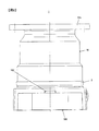
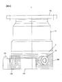
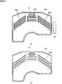
【解決手段】真空ポンプは、ポンプユニット10と、電子部品が搭載された回路基板104,105、回路基板104,105が収納されるユニットケース101および外部装置との接続に用いられるコネクタ102を有して、ポンプユニット10の動作を制御するコントロールユニット100と、を備え、ポンプユニット10のベース側面にはニットケース101を収納する凹部23が形成され、ニットケース101のポンプ吸気口側の上壁部110の内周側には回路基板104,105が接触固定され、上壁部110の外周側には、凹部23から露出している領域に複数の放熱フィン106が形成され、かつ、凹部23に収納される領域に該凹部壁面と接触する接触面113が形成されている。
【選択図】図1
Description
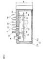
さらに好ましい実施形態では、基板は、複数の第1放熱フィンが形成された壁部領域の内周面と接触面が形成された壁部領域の内周面との両方に接触している。
さらに、コネクタをポンプ吸気口側壁部の外周面に配置するのが好ましい。
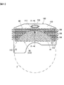
さらに好ましい実施形態では、ベースの側周面には、周方向に延びる第2放熱フィンが、ポンプ軸方向に1以上設けられている。
さらに好ましい実施形態では、複数の第1放熱フィンの延在方向に送風するファンを備える。
Claims (5)
- ロータを高速回転させて、ポンプ吸気口から吸入した気体をベースに設けられたポンプ排気口から排出するポンプユニットと、
電子部品が搭載された基板、前記基板が収納される筐体および外部装置との接続に用いられるコネクタを有して、前記ポンプユニットの動作を制御するコントロールユニットと、を備え、
前記ポンプユニットのベース側面には前記筐体を収納する凹部が形成され、
前記筐体のポンプ吸気口側壁部の内周側には前記基板が接触固定され、
前記ポンプ吸気口側壁部の外周側には、前記凹部から露出している領域に複数の第1放熱フィンが形成され、かつ、前記凹部に収納される領域に該凹部壁面と接触する接触面が形成されている、真空ポンプ。 - 請求項1に記載の真空ポンプにおいて、
前記基板は、前記複数の第1放熱フィンが形成された壁部領域の内周面と前記接触面が形成された壁部領域の内周面との両方に接触している、真空ポンプ。 - 請求項1または2に記載の真空ポンプにおいて、
前記コネクタを前記ポンプ吸気口側壁部の外周面に配置した真空ポンプ。 - 請求項1乃至3のいずれか一項に記載の真空ポンプにおいて、
前記ベースの側周面には、周方向に延びる第2放熱フィンが、ポンプ軸方向に1以上設けられている真空ポンプ。 - 請求項1乃至4のいずれか一項に記載の真空ポンプにおいて、
前記複数の第1放熱フィンの延在方向に送風するファンをさらに備えた真空ポンプ。
Priority Applications (1)
| Application Number | Priority Date | Filing Date | Title |
|---|---|---|---|
| JP2012261988A JP6102222B2 (ja) | 2012-11-30 | 2012-11-30 | 真空ポンプ |
Applications Claiming Priority (1)
| Application Number | Priority Date | Filing Date | Title |
|---|---|---|---|
| JP2012261988A JP6102222B2 (ja) | 2012-11-30 | 2012-11-30 | 真空ポンプ |
Publications (2)
| Publication Number | Publication Date |
|---|---|
| JP2014105695A true JP2014105695A (ja) | 2014-06-09 |
| JP6102222B2 JP6102222B2 (ja) | 2017-03-29 |
Family
ID=51027403
Family Applications (1)
| Application Number | Title | Priority Date | Filing Date |
|---|---|---|---|
| JP2012261988A Active JP6102222B2 (ja) | 2012-11-30 | 2012-11-30 | 真空ポンプ |
Country Status (1)
| Country | Link |
|---|---|
| JP (1) | JP6102222B2 (ja) |
Cited By (7)
| Publication number | Priority date | Publication date | Assignee | Title |
|---|---|---|---|---|
| JP2016008611A (ja) * | 2014-06-26 | 2016-01-18 | プファイファー・ヴァキューム・ゲーエムベーハー | シーグバーン段 |
| WO2018042151A1 (en) * | 2016-09-01 | 2018-03-08 | Edwards Limited | Pump with bidirectional heat transfer between pump housing and control housing |
| JP2018132024A (ja) * | 2017-02-17 | 2018-08-23 | エドワーズ株式会社 | コントローラ及び真空ポンプ装置 |
| JP2018141375A (ja) * | 2017-02-27 | 2018-09-13 | 株式会社島津製作所 | 電源一体型真空ポンプ |
| JP2019078233A (ja) * | 2017-10-25 | 2019-05-23 | 株式会社島津製作所 | 真空ポンプ |
| US10794385B2 (en) | 2018-02-02 | 2020-10-06 | Shimadzu Corporation | Vacuum pump with control device in relation to outer cylinder |
| EP4206474A1 (de) * | 2021-12-30 | 2023-07-05 | Pfeiffer Vacuum Technology AG | Vakuumpumpe |
Citations (8)
| Publication number | Priority date | Publication date | Assignee | Title |
|---|---|---|---|---|
| JPH04231699A (ja) * | 1990-12-28 | 1992-08-20 | Shimadzu Corp | 高速回転型真空ポンプ |
| JPH07103234A (ja) * | 1993-09-30 | 1995-04-18 | Ntn Corp | 磁気軸受スピンドル |
| JPH08338393A (ja) * | 1995-06-12 | 1996-12-24 | Koyo Seiko Co Ltd | 磁気軸受装置及びこれを含む真空ポンプ |
| JP3123370U (ja) * | 2006-04-28 | 2006-07-20 | 株式会社島津製作所 | ターボ分子ポンプ装置 |
| JP2006242069A (ja) * | 2005-03-02 | 2006-09-14 | Shimadzu Corp | ターボ分子ポンプ |
| JP2007032535A (ja) * | 2005-07-29 | 2007-02-08 | Boc Edwards Kk | 真空ポンプ装置とそのコントローラ |
| JP2008069661A (ja) * | 2006-09-12 | 2008-03-27 | Shimadzu Corp | 一体型ターボ分子ポンプ |
| JP2010053770A (ja) * | 2008-08-28 | 2010-03-11 | Vacuum Products Kk | 並列吸気ポンプ及びそれを用いた真空装置 |
-
2012
- 2012-11-30 JP JP2012261988A patent/JP6102222B2/ja active Active
Patent Citations (8)
| Publication number | Priority date | Publication date | Assignee | Title |
|---|---|---|---|---|
| JPH04231699A (ja) * | 1990-12-28 | 1992-08-20 | Shimadzu Corp | 高速回転型真空ポンプ |
| JPH07103234A (ja) * | 1993-09-30 | 1995-04-18 | Ntn Corp | 磁気軸受スピンドル |
| JPH08338393A (ja) * | 1995-06-12 | 1996-12-24 | Koyo Seiko Co Ltd | 磁気軸受装置及びこれを含む真空ポンプ |
| JP2006242069A (ja) * | 2005-03-02 | 2006-09-14 | Shimadzu Corp | ターボ分子ポンプ |
| JP2007032535A (ja) * | 2005-07-29 | 2007-02-08 | Boc Edwards Kk | 真空ポンプ装置とそのコントローラ |
| JP3123370U (ja) * | 2006-04-28 | 2006-07-20 | 株式会社島津製作所 | ターボ分子ポンプ装置 |
| JP2008069661A (ja) * | 2006-09-12 | 2008-03-27 | Shimadzu Corp | 一体型ターボ分子ポンプ |
| JP2010053770A (ja) * | 2008-08-28 | 2010-03-11 | Vacuum Products Kk | 並列吸気ポンプ及びそれを用いた真空装置 |
Cited By (11)
| Publication number | Priority date | Publication date | Assignee | Title |
|---|---|---|---|---|
| JP2016008611A (ja) * | 2014-06-26 | 2016-01-18 | プファイファー・ヴァキューム・ゲーエムベーハー | シーグバーン段 |
| WO2018042151A1 (en) * | 2016-09-01 | 2018-03-08 | Edwards Limited | Pump with bidirectional heat transfer between pump housing and control housing |
| JP2018132024A (ja) * | 2017-02-17 | 2018-08-23 | エドワーズ株式会社 | コントローラ及び真空ポンプ装置 |
| CN110249129A (zh) * | 2017-02-17 | 2019-09-17 | 埃地沃兹日本有限公司 | 控制器及真空泵装置 |
| JP2018141375A (ja) * | 2017-02-27 | 2018-09-13 | 株式会社島津製作所 | 電源一体型真空ポンプ |
| US11162510B2 (en) | 2017-02-27 | 2021-11-02 | Shimadzu Corporation | Power source-integrated vacuum pump |
| JP2019078233A (ja) * | 2017-10-25 | 2019-05-23 | 株式会社島津製作所 | 真空ポンプ |
| US10760578B2 (en) | 2017-10-25 | 2020-09-01 | Shimadzu Corporation | Vacuum pump with heat generation element in relation to housing |
| JP7022265B2 (ja) | 2017-10-25 | 2022-02-18 | 株式会社島津製作所 | 真空ポンプ |
| US10794385B2 (en) | 2018-02-02 | 2020-10-06 | Shimadzu Corporation | Vacuum pump with control device in relation to outer cylinder |
| EP4206474A1 (de) * | 2021-12-30 | 2023-07-05 | Pfeiffer Vacuum Technology AG | Vakuumpumpe |
Also Published As
| Publication number | Publication date |
|---|---|
| JP6102222B2 (ja) | 2017-03-29 |
Similar Documents
| Publication | Publication Date | Title |
|---|---|---|
| JP6102222B2 (ja) | 真空ポンプ | |
| JP5673497B2 (ja) | 一体型ターボ分子ポンプ | |
| JP7022265B2 (ja) | 真空ポンプ | |
| JP5286689B2 (ja) | 冷却ファンユニット | |
| TWI286185B (en) | Fan device | |
| JP6340798B2 (ja) | 送風ファン | |
| JP6575056B2 (ja) | 送風ファン | |
| US9157443B2 (en) | Turbo molecular pump device | |
| JP7088688B2 (ja) | 真空ポンプと真空ポンプの制御装置 | |
| JP7491352B2 (ja) | 流体機械 | |
| JP7087418B2 (ja) | 真空ポンプ | |
| CN108506225B (zh) | 电源一体型真空泵 | |
| US11415151B2 (en) | Vacuum pump, and control device of vacuum pump | |
| JP5316665B2 (ja) | ファン装置 | |
| WO2018150911A1 (ja) | コントローラ及び真空ポンプ装置 | |
| JP6834814B2 (ja) | 真空ポンプ用制御装置および真空ポンプ | |
| JP5392330B2 (ja) | 遠心ファン | |
| JP5516629B2 (ja) | ファン装置 | |
| JP5892122B2 (ja) | ファン装置及び電子機器 |
Legal Events
| Date | Code | Title | Description |
|---|---|---|---|
| A621 | Written request for application examination |
Free format text: JAPANESE INTERMEDIATE CODE: A621 Effective date: 20151008 |
|
| A977 | Report on retrieval |
Free format text: JAPANESE INTERMEDIATE CODE: A971007 Effective date: 20160617 |
|
| A131 | Notification of reasons for refusal |
Free format text: JAPANESE INTERMEDIATE CODE: A131 Effective date: 20160705 |
|
| A521 | Request for written amendment filed |
Free format text: JAPANESE INTERMEDIATE CODE: A523 Effective date: 20160902 |
|
| TRDD | Decision of grant or rejection written | ||
| A01 | Written decision to grant a patent or to grant a registration (utility model) |
Free format text: JAPANESE INTERMEDIATE CODE: A01 Effective date: 20170131 |
|
| A61 | First payment of annual fees (during grant procedure) |
Free format text: JAPANESE INTERMEDIATE CODE: A61 Effective date: 20170213 |
|
| R151 | Written notification of patent or utility model registration |
Ref document number: 6102222 Country of ref document: JP Free format text: JAPANESE INTERMEDIATE CODE: R151 |